

Sierra Series 200 Owner's Manual

Sierra Radio Systems
Series 200 Control System Owners Manual
Version 1.2

Table of Contents
Introduction
Hardware overview
Architecture
Configuring and installing the hardware boards
External connections
Configuring the control system
Introduction
Using DTMF
Using a PC and the CONFIG program
Basic configuration parameters
Radio port configuration
Setting audio levels
Using macros and creating custom commands
Saving the configuration to a file
Downloading configuration to the control system
Terminology and file system
Installing new firmware
Control system operation
Status indication LEDs
Command processor
Unlock codes
Site prefixing
Command reference guide
System-wide Audio Level Setting
Final System Installation Checklist
Appendix
Glossary
Receive qualification, squelch and transmit timing
Telemetry tones and level control
Software architecture and theory of operation
2

Introduction
This manual provides all the basic information you need to know to get your control
system installed, configured and on the air quickly. The control system is designed to
work "out of the box" in a standard configuration.
In most installations, all that is required is making the physical connections to power
and the radio equipment and setting a few basic configuration parameters such as call
sign and unlock code (password) and you are on the air.
The control system can be tailored to your particular needs in many ways. This manual
will give you a good overview of many of the parameters that can be changed to tailor
your system to meet your specific needs. Each port can be customized for a particular
behavior including repeaters, RF links, VOIP links, etc. Telemetry, command names,
and many other behaviors can also be customized.
Additional application notes are available on the SRS support web site that provides
detailed information on a variety of special topics.
Basic Checklist
As you read through this document, from time to time you will see a check box. This is
used to get your attention and indicates that this is something you really need to do to
get your control system working. This is part of your “basic check list”. Make sure you
read these notes.
You will also see open check boxes. These are for your to check them off as you go
to make sure you follow all the important steps.
3

Architecture Overview
The Series 200 control systems are very modular and scalable. The basic architecture
includes a master CPU board, from 1 to 8 Radio Control Boards (RCBs), and a backplane
to provide the interconnection between boards. Each RCB interfaces with an external
device such as a repeater, RF link, VOIP link, or computer and provides a basic signaling
interface that includes receive audio input, transmit audio output, COR (carrier present),
CTCSS/DCS decode logic input, and PTT (transmit control) output, serial radio control
I/O, and transmitter cooling fan output control.
The RCB can interface with many types of radio and computer equipment without
modification. In some cases, additional signal processing is required. The Series 200 is
designed to allow an additional signal interface board to be added to any of the RCB.
Optional signaling boards include special boards for microwave radio equipment, E&M
signaling, squelch detect, CTCSS tone generation, CTCSS detection, low pass filtering,
high pass filtering, TTL to RS-232 conversion, etc. The optional signaling interface
boards bolt on to the RCB to form a board pair or “module”.
A control system may be as simple as a CPU board, a single RCB and a short backplane.
A fully configured system may occupy an entire 19 inch card rack and contain a CPU,
up to 8 RCBs each with its own special signaling interface board, optional system
interface boards, and a large backplane and power supply board. In any configuration,
the system uses exactly the same CPU and RCB boards so a small system can easily
grow into a large system by simply adding more boards. Additionally, the software that
runs on the smallest configuration is exactly the same as the software for the largest
configuration.
The modular nature of the Series 200 control system make it not only easy to upgrade,
but also very easy to maintain. Boards can be quickly replaced from the front of the card
rack.
Very modular. Very scalable. Easy to maintain.
4

System Installation Checklist
Basic Checklist Summary
This is a reminder of the basic steps to get your control system configured and running.
Hardware installation and external connections
Configure all necessary jumpers on each board.
Plug boards into the backplane in the correct slots.
Connect the control system to an external 12 VDC power source.
Connect the CPU’s DB-9 connector to your PC.
Connect each RCB’s DB-9 connector to your external devices: radios (repeater, RF
links, remote base radios), VOIP computers, etc.
Software configuration
Set basic configuration parameters
Call sign
Set radio port configuration
Site prefix
Location ID
Unlock code
Set audio levels
Customize commands
Save the configuration to a file
Download configuration to the control system
5

Configuring the CPU Board
Most of the boards in the control system have one or more jumpers that can be set to
configure the board for various special purposes. The default configuration will be used
in most cases. Refer to the SRS Hardware Reference manuals for more details on each
board and the various jumper options.
Here are the default jumper settings for the CPU and RCB boards.
Basic Checklist
Make sure all CPU board jumpers in properly set.
The CPU board executes the main control system functions including routing the audio,
controlling the transmitter PTT lines, command decoding, and command response
telemetry generation. The CPU board also provides a serial RS-232 connection to a PC
for controller configuration, and 24 user defined I/O connections including digital
inputs, analog inputs and buffered digital outputs.
CPU Jumper Settings
JU1 - DVB Jumper
The DVB jumper enables or disables audio from the DVB_bus signal on the backplane.
This signal is audio generated from the optional Digital Voice Board or DVB.
"DIS”
"EN": When using the optional DVB in the system, JU1 MUST be in the enabled or
JU2 - Digital Pot Bypass Jumper
OU
IN:
JU3 - ICD Power
OU
IN: Install if using Con 5, the modular ICD jack for in-circuit programming.
NOTE: When using the ICD jack, you MUST cut the trace on the bottom of board to
enable the ICD power.
In normal operation when not using the DVB, the jumper MUST be in the
disabled or "DIS" position.
"EN" position.
T: Default. Set telemetry level under CPU control. This is the normal state for this
jumper.
Force telemetry pot to mid scale. This overrides the CPU level set for the master
telemetry generator.
T:
Default. For using Con 3, the 10 pin header connector for in-circuit
progamming.
6

JU4 - PGC Pullup
IN:
OUT: Remove the jumper when using Con 5, the ICD programming jack.
NOTE: When using the ICD jack, you MUST cut the trace on the bottom of
board.Default CPU Jumper Configuration
Default. Install this jumper for using Con 3, the 10 pin header connector for incircuit programming.
JU3 OUT
JU2 OUT
JU4 IN
All jumpers should be installed in the default positions indicated.
JU1 DVB
Default DIS
7

Configuring the Radio Control Board
The radio control board provides the audio interface, level set, audio mixing, local
telemetry (key up and CW ID) generation, serial radio control interface, extra user
programmable open collector outputs. One RCB is required for every radio or VOIP
computer in the system. Each RCB is configured to have one of several "personalities"
including a repeater, RF link, remotely controlled base station, or VOIP computer.
Basic Checklist
Make sure all RCB board jumpers are properly set.
JU1 - RX Port Select
You MUST
to the port you want to assign this board from 0 to 7.
No two boards can have the same rx port select value.
have one (and only one) jumper installed in this block. It must correspond
JU2 - CPU Address
You MUST
should be the same vale as the jumper installed in the Rx Port Select information above.
Jumpers
Port
0 out out out out
1 out out out IN
2 out out IN out
3 out out IN IN
4 out IN out out
5 out IN out IN
6 out IN IN out
7 out IN IN IN
install jumpers in the address header to match the port assignment. This
8 4 2 1
JU 3 - DTMF Filter Bypass
OUT:
IN: Bypass the DTMF filter and dirve the audio directly into the DTMF decoder.
Default. Takes the rx audio through a bandpass filter before it goes to the
DTMF decoder.
JU4 - Local (NO)
OUT: Default
IN: Install the jumper to enable the open collector output of Q2 to drive the "local
COR" input on the local CPU.
8

JU5 - PL_Filter (NC)
OUT:
IN:
Remove jumper is using a companion signaling board like the microwave or PL
encode / decode boards.
Default. Install the jumper when opearting the RCB without any signal
conditioning boards.
JU6 - DAC Pot Mid
OUT:
IN: Sets all four digital pots to mid scale.
Default. Allows digital pots to be set by the local CPU.
JU6 – Last Port Jumper (yes, there are two jumpers marked JU6)
OUT:
IN: Insert a jumper in this position if this is the last RCB in the card rack. The Last
JU7 - ADEN
OU
Not used at this time.
Default. Leave the jumper out for all RCB board except the last one.
Port jumper provides a termination on the high speed serial bus and will reduce
noise on the bus.
T: Default.
JU8 - TA2D
OU
T: Default
Not used at this time.
9

Default RCB Jumper Configuration
Radio
Note: There are two jumpers labeled “JU6”, the “DAC pot mid” jumper and the “last
port” jumper.
The RCB jumpers should all be set to the defaults. Additionally, each RCB must be
jumpered with the proper addresses set. Each RCB must be assigned one unique address
from 0 to 7.
Jumper block ____ must be set with a single jumper to properly route the Rx
audio to the proper backplane bus signal.
10

Hardware Orientation
Power Supply Board
The power supply board provides a power switch and a power LED.
The power switch provides primary power to the CPU, RCB and accessory boards. The
12 VDC from the external power connector is routed to all boards in the card cage and is
not switched.
The power LED indicates that power is being supplied to the rest of the control system.
CPU Board
The CPU board provides a power LED, hardware resest switch, optional I/O connector
(DB25) and the male DB9 RS-232 serial connection to a PC used for computer-based
configuration and control.
To trigger a hardware reset, press the hardware reset button.
Radio Control Board (RCB)
The RCB board provides a power LED, a set of 6 channel status LEDs, a female DB15
auxiliary I/O connector and a female DB9 radio I/O connector.
The channel status LEDs indicate COR (active Rx signal present), PTT (transmitter
active), CTCSS/DCS decode, DTMF decode and two user programmable output bits.
The DB15 auxiliary connector provides many convenient functions including
11
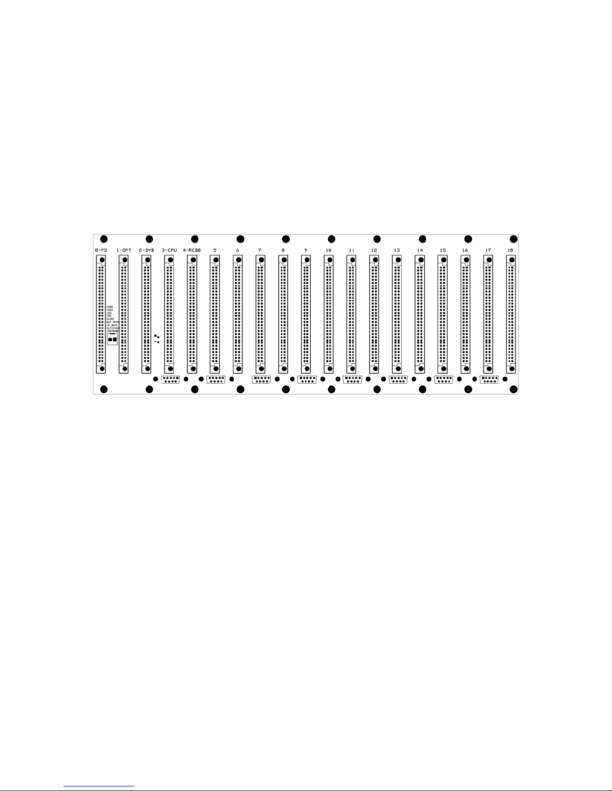
Configuring the Backplane
The system will come configured as ordered. You will need to plug the various boards
into the correct slots in the backplane. If your system is already assembled as desired,
you can skip this section.
The Power Supply, CPU and the first Radio Control Board (RCB) must be placed in
specific slots. After the first RCB, all additional RCBs must be installed next to each
other. There can be no gaps between the CPU and any of the RCBs. When optional
microwave or CTCSS signaling boards are used, these boards are paired with each RCB
and are installed in the slot to the right of the RCB.
The basic control system consists of the card rack with backplane, a power supply board,
CPU board and one Radio Control Board (RCB) for each receiver/transmitter in the
system. All controllers have the first 5 slots assigned as follows…
Slot Assignment
0 Power supply
1 Reserved for future expansion
2 Reserved for future expansion
3 CPU
4 Radio control board - port 0
Radio Control Boards are installed starting in slot 4. Every radio requires a radio control
board. Radio Control Boards must be plugged into the backplane next to each other and
are named port 0 through port 7. There can be NO gaps between boards after port 0.
12

A basic 8 port controller will have the following configuration…
Typical 8 port controller
Slot Assignment
0 Power supply
1 Reserved for future expansion
2 Reserved for future expansion
3 CPU
4 Radio control board - port 0
5 Radio control board - port 1
6 Radio control board - port 2
7 Radio control board - port 3
8 Radio control board - port 4
9 Radio control board - port 5
10 Radio control board - port 6
11 Radio control board - port 7
12-18 Empty
Each port is assigned a "personality" which defines the basic behavior of that RCB.
Personalities can be either a repeater, RF link, VOIP link or remotely controlled base
station. The different personalities of a system can be assigned to the ports in any
desired order. The user level and many of the configuration commands refer to specific
ports by a number, often referred to as the link number because most of them will be
links. Configuration of the system is simpler if the number by which a port will be
referred is same as the port number. A typical configuration would have a primary
repeater in port 0, RF links in the next set of ports, VOID links, remote bases and then
any additional repeaters, For example, 2 repeaters, 4 links, and 2 remote bases would be
configured as…
Slot Assignment
0 Power supply
1 Reserved for future expansion
2 Reserved for future expansion
3 CPU
4 Radio control board - port 0 – Repeater 1
5 Radio control board - port 1 – Link 1
6 Radio control board - port 2 – Link 2
7 Radio control board - port 3 – Link 3
8 Radio control board - port 4 – Link 4
9 Radio control board - port 5 – Remote base 1, link 5
10 Radio control board - port 6 – Remote base 2, link 6
11 Radio control board - port 7 – Repeater 2, Radio 7
12-18 Empty
Special Note: There must
not be any empty slots between radio control boards. If there
is a gap between boards, all ports up to the gap will work fine but all subsequent ports
will not function properly. This breaks the high speed serial control bus which
communicates the state of COR, PL decode, PTT, fan control, user outputs and DTMF
signals to the master CPU.
13

Using Optional Signaling Boards
If optional signaling boards such as t
he microwave radio board or PL encode / decode
boards are used, they are placed in the slot immediately to the right of the radio control
board. A typical 6 port microwave hub would be configured as…
Slot Assignment
0 Power supply
1 Reserved for future expansion
2 Reserved for future expansion
3 CPU
4 Radio control board - port 0 - Microwave radio 1
5 Microwave E&M signaling interface board
6 Radio control board - port 1 - Microwave radio 2
7 Microwave E&M signaling interface board
8 Radio control board - port 2 - Microwave radio 3
9 Microwave E&M signaling interface board
10 Radio control board - port 3 - Microwave radio 4
11 Microwave E&M signaling interface board
12 Radio control board - port 4 - Microwave radio 5
13 Microwave E&M signaling interface board
14 Radio control board - port 5 - Microwave radio 6
15 Microwave E&M signaling interface board
16-18 Empty
Any combination of Radio Control Boards with or without optional signaling boards
may be used. For example, a site with 1 repeater, 2 microwave radios, 2 narrowband RF
links, one with PL encode/decode, one VOIP interconnect to the internet and one
remote base radio.
Slot Assignment
0 Power supply
1 Reserved for future expansion
2 Reserved for future expansion
3 CPU
4 Radio control board - port 0 - Repeater
5 Radio control board - port 1 - Microwave radio, link 1
6 Microwave E&M signaling interface board
7 Radio control board - port 2 - Microwave radio, link 2
8 Microwave E&M signaling interface board
9 Radio control board - port 3 - RF link 3
10 PL encode / decode signaling interface board for RF link 1
11 Radio control board - port 4 - RF link 4
12 Radio control board - port 5 - VOIP internet interconnect board
13 Radio control board - port 6 - remote base radio
14-18 Empty
14
External Connections
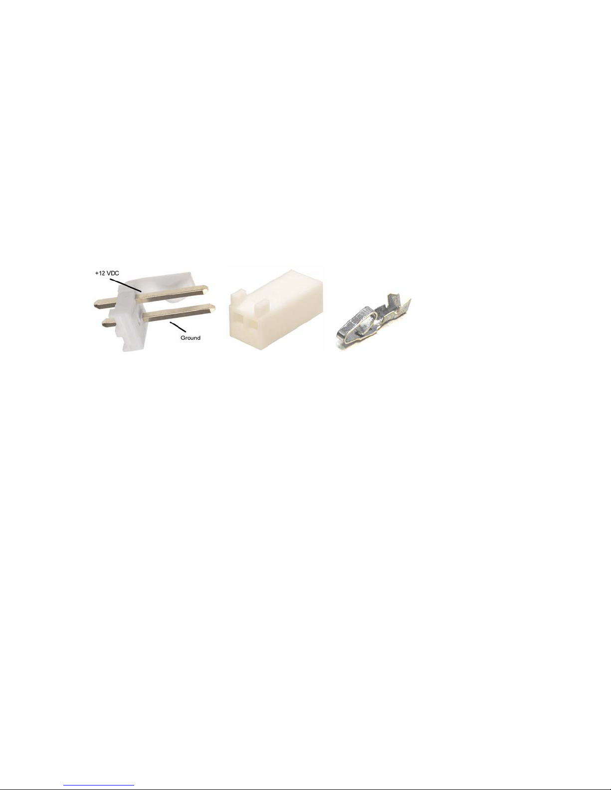
Backplane DC Power Connection
Basic Checklist
Make sure you connect the control system to an external 12 VDC power source.
The control system typically uses +12 to +14 VDC and will operate down to10 VDC with
no problems. The external DC power is supplied through a 2 pin connector mounted on
the back of the control system.
The alignment tab is on the top of the connector. As you look at the back of the
backplane, the left pin is +12 VDC in and the right pin is ground.
Make sure the connector is plugged in correctly. The control system is internally fused
on the power supply board just in case something gets shorted out. The fuse value
should be 3 amps.
15

CPU Board Connections
The are three types of external connections on the CPU board, the configuration serial
port connector, the general purpose I/O connector and the in-circuit programming
connectors.
Basic Checklist
Make sure you connect the CPU’s DB-9 connector to your PC so you can use the
CONFIG program to configure your control system.
CPU Board Serial Port Connector
This connection is a standard RS-232 ASCII interface between the control system and
your computer. It is used to configure the control system under computer control.
Connector pin outs…
Pin 2 - Rx data in
Pin 3 - Tx data out
Pin 5 - Ground
The configuration serial port is the male DB-9 connector on the front edge of the board.
This connection is not used in normal operation. When using the optional PC-based
configuration software, the PCs serial port is plugged in this connector.
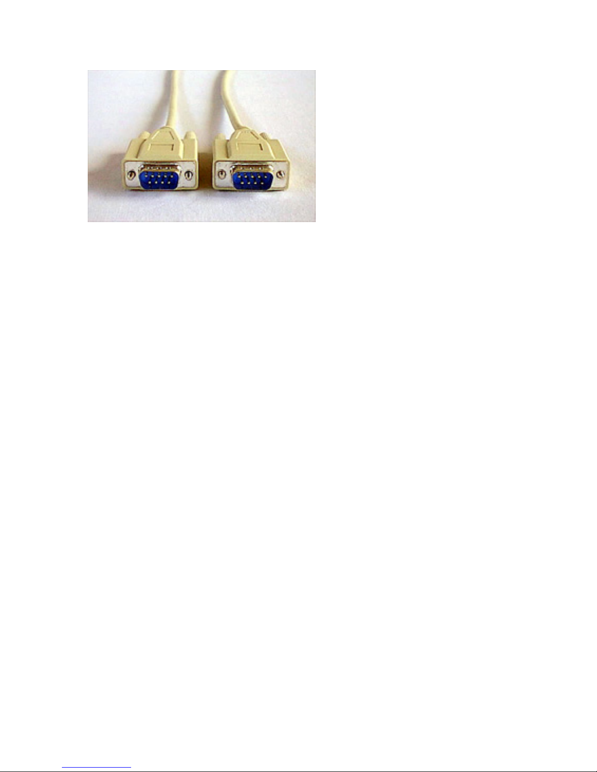
PC Configuration Cable
This cable connects your computer to the main CPU board for upload and downloading
the control systems configuration. The programming cable is a straight through cable.
Connections required are pin 2 to 2, 3 to 3 and 5 to 5. The crossover of txd / rxd is done
on the CPU board. Note that most female to female cable available in computer stores
swap pins 2 and 3, so you may need to make your own cable.
16

Con_3 - In-Circuit Progamming Connector
The in-circuit programming connector, Con_3, is used to download new versions of
firmware to the main CPU. This is a 10 pin header connector designed to be used for incircuit programming with an ME Labs in-circuit programmer.
General Purpose I/O Connector
The GPIO connector provides 24 I/O signals that can be used for a variety of purposes.
The signals inlcude 8 TTL level digital inputs with internal logic pullups, 8 open
collector buffered outputs, 8 analog to digital converter inputs and ground.
All 24 I/O signals are protected from over voltage conditions using transient voltage
suppression devices.
Use
Pin
1 Analog input
2 Analog input
3 Analog input
4 Analog input
5 Digital output
6 Digital output
7 Digital output
8 Digital output
9 Digital input
10 Digital input
11 Digital input
12 Digital input
13 Digital input
Digital inputs are pulled up with a 10k resistor and must be either ground or +5 VDC.
Analog inputs must be between 0 and +5V.
Digital outputs are buffered open collector outputs that can sink up to 500 ma.
Pin
Use
14 Analog input
15 Analog input
16 Analog input
17 Analog input
18 Digital output
19 Digital output
20 Digital output
21 Digital output
22 Digital input
23 Digital input
24 Digital input
25 Ground
17

Radio Control Board (RCB) Connections
Basic Checklist
Make sure you connect each radio, computer or other external device to the control
system RCBs using the DB9 connector on the front of the RCB.
DB-9 radio connections
The control system has a female DB-9 connector which
is used to connect to an external device including a
repeater, link radio, remote base radio or computer
system. The cable should have a male connector.
This picture is the DB-9 connector as seen on the front of
the control system.
Pin 1
Pin 2
Pin 3
Pin 4
Pin 5
Pin 6
Pin 7
Pin 8
High impedence Rx audio input from receiver. Input can range from 0 to 2v
peak-to-peak. Anything around 1 v p/p works great. Rx audio may be
unsquelched.
COR ("Carrier Operated Relay"), an active low signal. When the carrier is
present, the COR pin must be pulled to ground.
Ground
PTT ("Push To Talk"), an active low signal. This is an open collector output that
pulls to ground when the controller wants to key the transmitter. The output
can sink a maximum of 250 ma.
Low impedence audio output to the transmitter. Nominal 1v p/p output. Can
be adjusted from 0 to about 4v p/p.
PL decode input active low. Pull this input pin low to indicate the presence of
the proper PL or DPL tone being decoded.
Serial data input. TTL level ASCII input used with serial programmable remote
base radios.
Serial data output. TTL level ASCII input used with serial programmable
remote base radios.
Fan control output. This is an open collector output which is pulled to ground
Pin 9
18
to actuate a relay that will turn on the cooling fan on the transmitter. The output
can sink a maximum of 250 ma.
Radio control cable.
The radio co
ntrol cable connects the control system to the individual radios. The cable is
a 9 pin, shielded cable with all 9 connections wired straight through, with pin 1 to 1, 2 to
2, etc.
In-circuit programming connector
This is a 10
pin, dual row header connector. This connection is not used in normal
operation. This is the connection where the in-circuit programmer in plugged in when
downloading new versions of firmware to the RCB's local CPU.
RCB Accessory Connector "Aux_IO"
This is a female DB-15 which provid
es various optional connections for external device
control, testing and alternate programming connections for the local CPU on the radio
control board.
Typical cable for external device control
15 Open collector user output #1
8 Open collector user output #2
7 Open collector user output #3
14 Open collector user output #4
6 Open collector user output #5
11 Open collector PTT Output
12 Open collector Tx cooling fan output
13 Ground
19
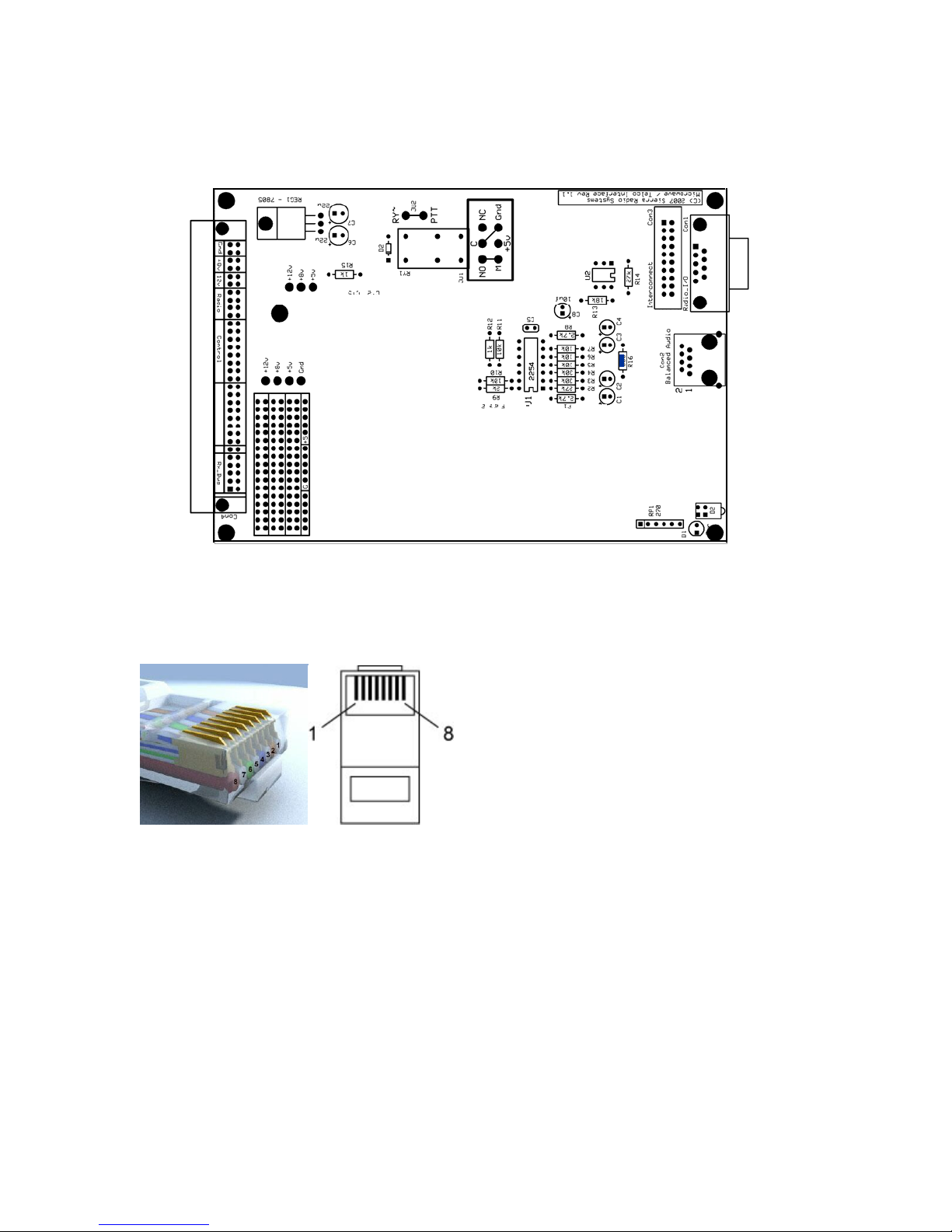
Microwave Radio Interface Board
This board can be configured to drive a microwave radio that requires balanced audio
and E & M signaling.
Modular jack pin outs
Pin Use
2 Balanced Tx audio out (600 Ohms)
3 PTT "M" signaling
4 Ground
5 Negative voltage input for PTT keying circuit (nomially -24v)
6 COR input, active low
7 Balanced Rx audio input (600 Ohms)
8 Balanced Rx audio input (600 Ohms)
1 Balanced Tx audio out (600 Ohms)
20

AS-3 Audio Squelch Board
High impedence Rx audio input from receiver. Input can range from 0 to 2v
Pin 1
peak-to-peak. Anything around 1 v p/p works great. Rx audio may be
unsquelched.
Pin 2
Pin 3
Pin 4
Pin 5
Pin 6
Pin 7
Pin 8
Pin 9
COR ("Carrier Operated Relay"), an active low signal. When the carrier is
present, the COR pin must be pulled to ground.
Ground
PTT ("Push To Talk"), an active low signal. This is an open collector output that
pulls to ground when the controller wants to key the transmitter. The output
can sink a maximum of 250 ma.
Low impedence audio output to the transmitter. Nominal 1v p/p output. Can
be adjusted from 0 to about 4v p/p.
PL decode input active low. Pull this input pin low to indicate the presence of
the proper PL or DPL tone being decoded.
Serial data input. TTL level ASCII input used with serial programmable remote
base radios.
Serial data output. TTL level ASCII input used with serial programmable
remote base radios.
Fan control output. This is an open collector output which is pulled to ground
to actuate a relay that will turn on the cooling fan on the transmitter. The output
can sink a maximum of 250 ma.
21

Radio I/O – II (RIO-II) Board
22

Configuring the Control System
23

Control System Configuration Software
Overview
Sierra Radio Systems supplies a software configuration program called “config” that
allows the system administrator to configure the control system through a Windowsbased PC. Config can be used in may different ways to configure a Sierra Radio Systems
control system. Features include a graphic user interface to enter and modify control
system parameters, run files control commands called scripts, reading configuration files
into the program and writing the configuration back out to a file, interactively set audio
levels, and more. The config program can be used “offline” to create and edit a
configuration without a control system. Config uses the serial port on the master CPU
board to transfer information to and from the control system. Config runs on a standard
Windows PC that supports a serial port. A USB to serial adapter can be used is no serial
port is available on the PC.
If you want to a detailed understanding of the config program and data files, skip
forward to section II. If you just want to jump right in and configure your control
system then here we go…
Section I - Setting up a New Configuration
The built in wizard helps you walk through the steps of creating a new configuration.
As you can see from the wizard the steps are…
1. Reset all parameters
2. Customize basic parameters
3. Configure each radio port
4. Set audio levels
5. Set command names and macros
6. Save configuration file
7. Download configuration to the controller
24

The steps are simple and in some cases some steps can even be skipped. Here is a
description of what each step does…
1. Reset all parameters
This will set all the configuration parameters in the config program to their normal
default values. Then the configuration file “
default.cfg” will be loaded. This is the
starting point for your new controller configuration.
2. Customize basic parameters
At a minimum, the controller should be personalized with its call sign, site prefix,
location ID and unlock codes. For testing purposes, the defaults are fine but systems
typically need to have their own unique call sign. Also for security reasons, the unlock
code should be changed to something only the site administrator knows. If there are
multiple control systems in a network, the site prefix and location ID should be changed
to something unique to avoid confusion and proper network operation.
25
Call signs and location IDs can be up to 20 characters.
The site prefix should be 1, 2 or three unique digits. All site prefix codes are # followed
by the parameter that you enter. If you enter 123, then your prefix will be #123.
Unlock codes should be something that only system administrators know. The
minimum requirement is to specify unlock codes 1 and 2.
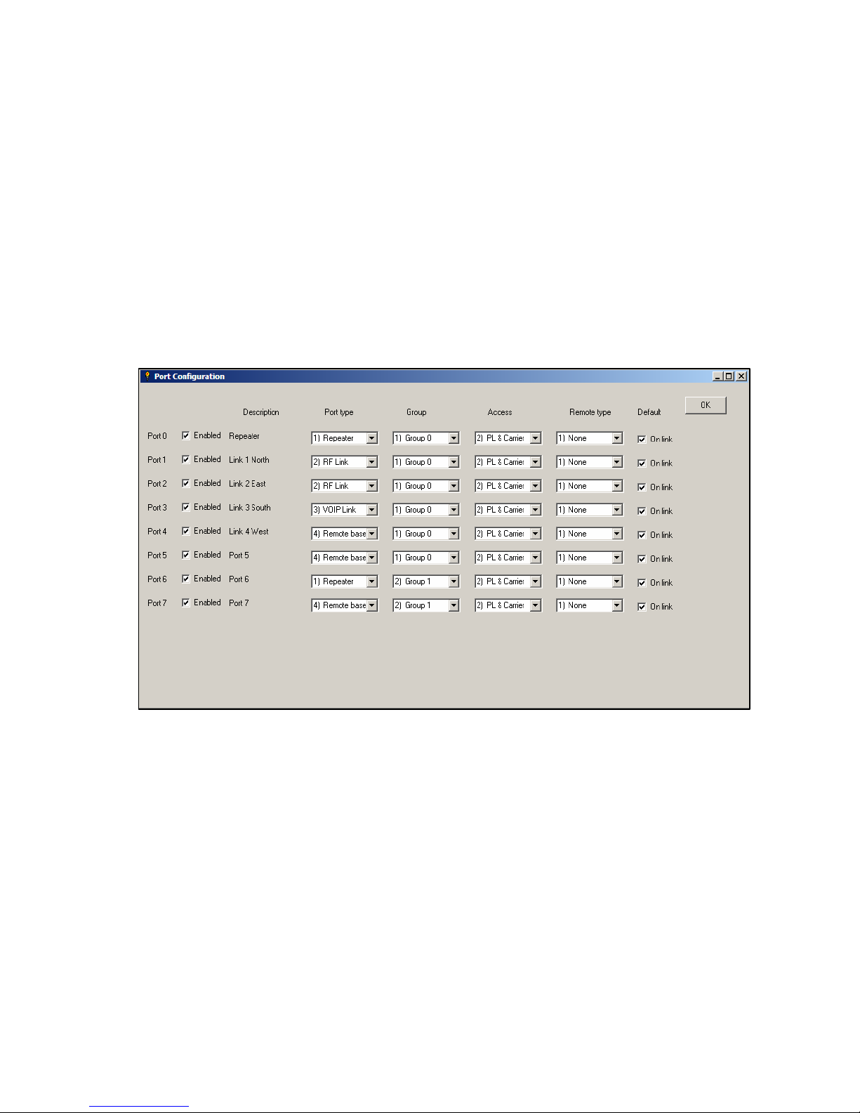
3. Configure Each Radio Port
Each port is assigned a personality depending on the type of equipment and desired
behavior. Port types include repeaters, link, VIOP gateways, and remote bases.
Differences between port types
The table below describes the differences in behavior between ports configured as
repeaters, links, irlp nodes, and remote bases. Some of these are just the default
behavior that is created when the port type is defined, and can be changed, either by
port type or by individual port. Others (such as ability to accept commands) are built
into the programmed behavior of the port type.
26

Repeater port type
Used for normal repeater operation. Loops repeater receiver audio to transmitter, uses
transmitter carrier delay, mutes all DTMF audio to the transmitter but passes DTMF to
the links, etc.
Link port type
Used for RF or “private” internet VOIP point to point network links. Does not loop
audio, passes all DTMF tones, has no carrier delay unless the signal comes from a
repeater input, etc.
VOIP port type
Used for IRLP, EchoLink and other “public” VOIP systems. Does not loop audio, does
not pass DTMF or any locally generated telemetry, turns off carrier delay by default, etc.
Remote base port type
Used for remotely controlled base stations including Icom, Yaesu, Kenwood serial
programmed radios, BCD and channelized radios. Does not loop audio, does not pass
DTMF or any locally generated telemetry, carrier delay turned off by default, etc
27

If the port type is “Remote Base” then the remote base type should be selected for the
controller to generate the correct frequency and mode control data sent to the remote
base radio.
Groups
The control system can support up to 3 independent groups of ports. The default is for
all ports to operate together as group 0. Additional groups can be created by assigning
group #1 or #2 to a port. Each group will act as if its members are the only radios in the
system. All groups must use the same command set and will generate the same type of
telemetry.
Access
This defines the combination of carrier detect (COR) and CTCSS/DCS signaling
required for a valid signal present indication from each receiver.
Enabled
When checked, this makes that specific RCB (radio control board) available to the
system. When unchecked, it is logically disconnected as if the board was pulled from
the card cage.
Default on link
When checked, this port will default to be connected to the other ports in its group when
the system is reset or a site normal command is executed. When unchecked, this port
will be defaulted in the disconnected mode.
28
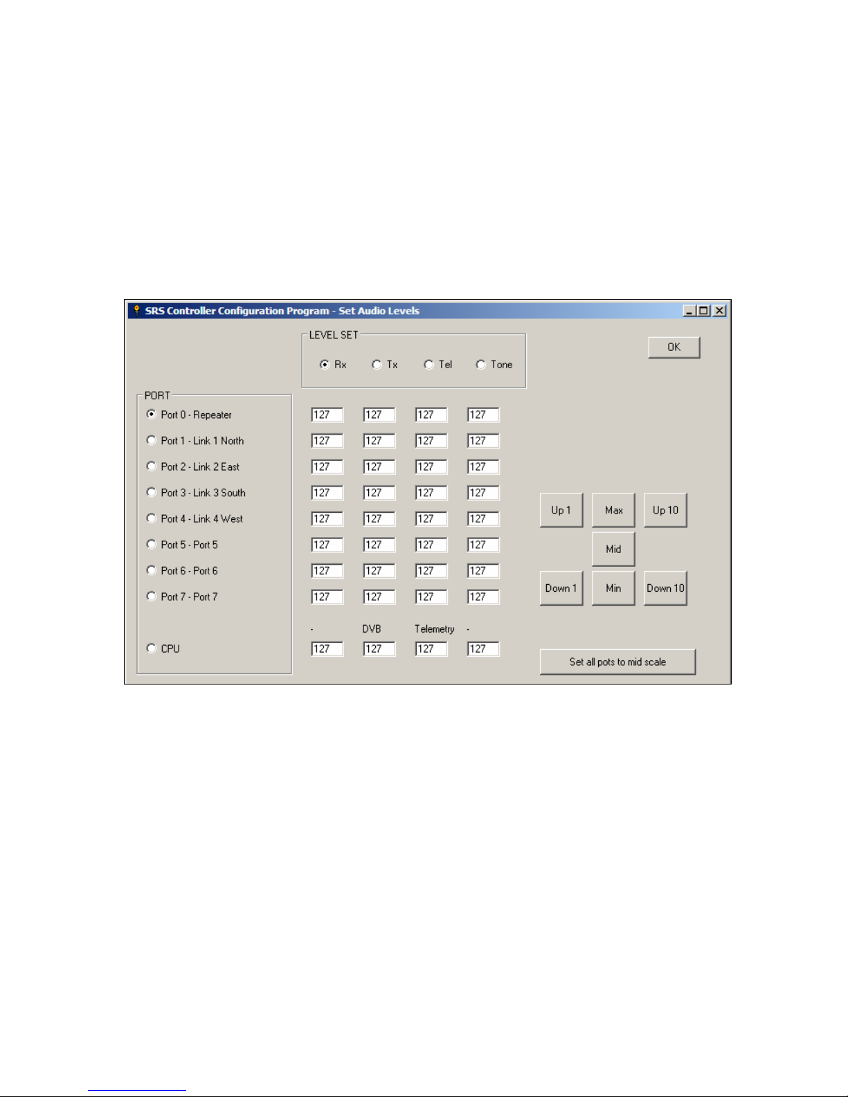
3. Set Audio Levels
Each radio control board has 4 digitally controlled audio level set potentiometers. The
control the receiver and transmitter audio levels, telemetry level generated by the RCB
that is sent only to that specific transmitter and an auxiliary audio input level. The local
telemetry generator per transmitter is used for dial tone, busy signal, function complete,
CW ID and other functions. The auxiliary audio input is typically used for sub-audible
CTCSS and other externally generated signaling tones.
Audio level set dialog box
Use the “radio buttons” to select the specific audio level you want to set. Pick a port on
the left and a level set pot on the top. Then click one of the level adjust buttons on the
right side to change the pot level.
Interactive, real time audio level setting from the computer.
This is an interactive dialog box. Most commands and parameters entered on most
screens are not sent to the control system until the “download configuration to control
system” is performed. In the case of the audio level set screen, as you change audio
level values, they are sent real time to the control system. This allows you to set all
audio levels in the control system while connected to actual radio and test equipment.
This is the equivalent of adjusting up to 36 little audio pots but without having to bring
your little green screwdriver.
Each audio level can be set between 0 and 255. 0 is minimum (“Min”) which shuts off
the audio, 127 is Mid scale and 255 is maximum (“Max”) audio. Audio is adjusted by
29

pressing one of the buttons on the right side of the screen. It Up 10 and Down 10 lets
you move quickly across the range of the pot while Up 1 / Down 1 let you fine tune
your levels.
4. Set Command Names and Macros
The control system comes with several dozen built in commands. In the simplest use
mode, all you need to do is select your own personal unlock code and use all the generic
built in commands and everything will work fine. This relies on the unique unlock code
for security, which for most situations may be good enough. It is often desirable to have
some or all of the user commands assigned unique “command names”. This is
accomplished by using the user command macro features of the control system. Up to
250 user macros can be created. A macro can be a simple mapping of a custom
command name to a single built in controller command. For example the built in
command C310 will send the CW ID for the system. If you wanted to have your own
command 123 send a CW ID you would create a macro with the name 123 and the
macro string contents would be C310.
Macros allow you to string several commands together. You can create a command that
will perform multiple actions with a single command name. For example you can create
a command 234 which will execute the internal commands C3311 C3312 C3313 C3304
C351 which will turn on links 1, 2 and 3, turn off link 4 and set the repeater in CTCSS
mode. Macros can even contain other macros.
Special note: If you have any special script files that need to be run to finalize your
configuration, this is the time to do it.
5. Save Configuration File
After you create your configuration, you should save it to a disk file so you can easily
edit or re-download your configuration in the future into the same or another control
system. To generate your configuration file, select File / Save As. You well see a dialog
box like this…
30
 Loading...