

Sierra QuadraTherm 640i Series,QuadraTherm 780i Series Instruction Manual
QuadraTherm® 640i/780i Series
Insertion and In-Line Mass Flow Meters
Preliminary Instruction Manual
Part Number: IM-640i/780i Rev.v1
November 2012
1

GLOBAL SUPPORT LOCATIONS: WE ARE HERE TO HELP!
CORPORATE HEADQUARTERS
5 Harris Court, Building L Monterey, CA 93940
Phone (831) 373-0200 (800) 866-0200 Fax (831) 373-4402
www.sierrainstruments.com
EUROPE HEADQUARTERS
Bijlmansweid 2 1934RE Egmond aan den Hoef
The Netherlands
Phone +31 72 5071400 Fax +31 72 5071401
ASIA HEADQUARTERS
Second Floor Building 5, Senpu Industrial Park
25 Hangdu Road Hangtou Town
Pu Dong New District, Shanghai, P.R. China
Postal Code 201316
Phone: + 8621 5879 8521 Fax: +8621 5879 8586
IMPORTANT CUSTOMER NOTICE- OXYGEN SERVICE
Sierra Instruments, Inc. is not liable for any damage or personal injury, whatsoever, resulting from the use
of Sierra Instruments standard mass flow meters for oxygen gas. You are responsible for determining
if this mass flow meter is appropriate for your oxygen application. You are responsible for cleaning
the mass flow meter to the degree required for your oxygen flow application.
© COPYRIGHT SIERRA INSTRUMENTS 2012
No part of this publication may be copied or distributed, transmitted, transcribed, stored in a
retrieval system, or translated into any human or computer language, in any form or by any means,
electronic, mechanical, manual, or otherwise, or disclosed to third parties without the express
written permission of Sierra Instruments. The information contained in this manual is subject to
change without notice.
TRADEMARKS
QuadraTherm™, iTherm™ and iAnywhere™ are trademarks of Sierra Instruments, Inc. Other product
and company names listed in this manual are trademarks or trade names of their respective
manufacturers.
2

Table of Contents
Chapter 1: Introduction & Product Description
Product Description
Technical Assistance
............................................................................................................................ 5
...................................................................................................................... 7
.................................................................................... 5
Principle of Operation ........................................................................................................................ 8
iTherm™ Electronics Features
Enclosure Options
........................................................................................................................... 10
............................................................................................................ 9
Chapter 2: Installation & Wiring ........................................................................................................ 11
Installation Overview ....................................................................................................................... 11
Installing the Flow Meter .................................................................................................................. 13
Cold Tap Installation
Hot Tap Installation
........................................................................................................................ 13
......................................................................................................................... 14
Wiring Connections ......................................................................................................................... 17
Input Power Wiring
Alarm Output Wiring
........................................................................................................................ 18
................................................................................................................... 21
Remote Sensor Wiring .................................................................................................................... 24
Chapter 3: Operation & Programming
............................................................................................ 25
Start-up Routine ......................................................................................................................... 26
Level 1: Main Menu ..................................................................................................................... 26
Level 2: Sub-Menu (Password Protected) ..................................................................................... 28
Calibration (Sub-Menu) ............................................................................................................... 29
Calibration (Sub-Menu): Gas Type –“iTherm Dial-A Gas” ............................................................... 30
Calibration (Sub-Menu): Flow Units .............................................................................................. 32
Calibration (Sub-Menu): Temperature Unit .................................................................................... 33
Calibration (Sub-Menu): MenuTune .............................................................................................. 33
Calibration (Sub-Menu): Low Flow Cut Off .................................................................................... 34
Calibration (Sub-Menu): Full Scale Flow ....................................................................................... 35
Process Pressure (Sub-Menu) ..................................................................................................... 35
Process Pressure (Sub-Menu): Pressure Units .............................................................................. 36
Process Pressure Sub-Menu: Process Pressure ............................................................................ 36
Totalizer (Sub-Menu) .................................................................................................................. 37
Totalizer Sub-Menu: Reset Pulse Count ....................................................................................... 37
Totalizer (Sub-Menu): Units Per Pulse .......................................................................................... 39
Totalizer (Sub-Menu): Totalizer On/Off ......................................................................................... 39
Output Adjust (Sub-Menu): Flow, Pressure and Temperature ......................................................... 42
Reference Conditions (Sub-Menu): Standard and Normal .............................................................. 45
Change Password, Change Language .......................................................................................... 45
Restore Factory .......................................................................................................................... 45
Box Car ..................................................................................................................................... 45
Chapter 4: Troubleshooting & Repair
Troubleshooting the Flow Meter
Returning Equipment to Factory
................................................................................................ 49
.................................................................................................... 49
.................................................................................................... 51
Appendix A: Product Specifications ................................................................................................. 52
Appendix B: Smart Interface Installation ........................................................................................... 60
3

Warning!
the flow meter nameplate for specific flow meter approvals before any hazardous location installation.
Warning!
permit. The manufacturer of the hot tap equipment and/or the contractor performing the hot tap is
responsible for providing proof of such a permit
Warning!
Warning!
when wiring this unit to a power source and to peripheral devices. Failure to do so could result in injury or
death. All AC power connections must be in accor dance with published CE directives.
Warning!
over-heating of the sensors and/or damage to the electronics.
Warning!
Warning!
Caution!
to any master control system. Adjustments to the electronics will cause direct changes to flow control settings.
Warnings and Cautions
Agency approval for hazardous location installations varies between flow meter models. Consult
Hot tapping must be performed by a trained professional. U.S. regulations often require a hot tap
All wiring procedures must be performed with the power off.
To avoid potential electric shock, follow National Electric Code safety practices or your local code
Do not power the flow meter with the sensor remote (if applicable)wires disconnected. This could cause
Before attempting any flow meter repair, verify that the line is de-pressurized.
Always remove main power before disassembling any part of the mass flow meter.
Before making adjustments to the device, verify the flow meter is not actively monitoring or reporting
Caution!
higher pressure rating as the main pipeline.
Caution!
accuracy of the flow meter. You cannot add or subtract wire length without returning the meter to the
factory for re-calibration.
Caution!
at full gas flow before installing the meter.
Caution!
Caution!
follow these precautions to minimize the risk of damage:
All flow meter connections, isolation valves and fittings for hot tapping must have the same or
Changing the length of cables or interchanging sensors or sensor wiring will affect the
When using toxic or corrosive gases, purge the line with inert gas for a minimum of four hours
The AC wire insulation temperature rating must meet or exceed 80°C (176°F).
Printed circuit boards are sensitive to electrostatic discharge. To avoid damaging the board,
before handling the assembly, discharge your body by touching a
grounded, metal object
handle all cards by their edges unless otherwise required
when possible, use grounded electrostatic discharge wrist straps when handling
sensitive components
4

Chapter 1: Introduction & Product Description
From Sierra’s beginning over forty years ago, Founder Dr. John G. Olin was driven by the
vision of supplying industrial customers with the world’s most accurate thermal mass flow
meter. And, he knew it was a “sensor” game.
The development of an industrialized metal-sheathed sensor in the early 80s was Sierra’s
first big step, but Dr. Olin is a driven innovator, and this was only the beginning for
someone who saw “Thermal Mass Flow” as his life’s work. Many successful innovations
followed, but in 1999 Sierra experienced a major breakthrough with the introduction of
their patented no-drift DrySense™ thermal mass velocity sensor. Sierra engineers now
recognized they were on the cusp of realizing Dr. Olin’s vision.
Realizing the Vision: Thermal technology, by its very nature, uses the physics of heat
transfer and and conservation of energy in a closed system to measure mass flow rate. This
means that for a thermal mass flow meter to achieve the greatest accuracy, it must solve
the First Law of Thermodynamics (Heat Energy In = Heat Energy Out) for each data point.
As you can imagine, solving the First Law in a flow instrument was no easy task. By Dr.
Olin’s own accounting, decades of “hard-nosed dedication to excellence” by himself and
Sierra’s engineering team, years of testing, and his stack of yellow note pads over five feet
high, jammed with his handwritten equations and designs, finally yielded the secret in the
form of two revolutionary technologies—QuadraTherm™ and iTherm™, now both
patented worldwide.
The QuadraTherm Sensor: Traditional thermal sensors have two sensors-–one
temperature sensor and one velocity sensor, each in a separate probe. QuadraTherm (the
term “Quad” meaning “four”) introduces four sensors—three precision platinum
temperature sensors and one patented DrySense mass velocity sensor. Performance
improvements never before possible are gained as the QuadraTherm Technology isolates
forced convection (the critical variable for measuring gas mass flow rate) by calculating
and then eliminating unwanted heat-transfer components, like sensor stem conduction, one
of the major causes of false flow readings.
iTherm, the Brains Behind it: iTherm is the true “Brain” of the instrument and a
revolutionary, living, learning algorithm set made possible by today’s hyper-fast
microprocessors and QuadraTherm sensor inputs. iTherm manages changes in gas flow,
temperature and pressure, as well as outside temperature, via a comprehensive heattransfer model. The result of iTherm is a proprietary, fundamentally different gas mass
flow rate calculation using all pertinent variables for the most precise, stable and accurate
mass flow measurement possible.
Website & Downloads
QuadraTherm microsite:
www.sierrainstruments.com/quadratherm
Download this manual:
www.sierrainstruments.com/quadrathermIM
5

Features and Benefits
Accuracy (air) +/- 0.5% of reading from 50% to 100% of full scale
+/-0.5% of reading plus 0.5% of full scale from 0% to 50% of full scale
Patented vastly improved thermal sensor element for high accuracy
Patented DrySense™ Technology for long term drift stability; lifetime warranty
Instrument-optimized proprietary iTherm Gas Library for application independence
Sensor design improvements to eliminate downdraft effects from probe
Dial-A-Gas®: change gas and engineering units in the field, on the fly with the push of a
button
Dial-A-Pipe™: Use insertion version on different pipe sizes, set up on the fly with the push of
a button
Multivariable: simultaneous measurement of mass flow rate, process temperature, and
pressure
CE approved
FM approval pending
Digital communications suite pending
Using This Manual
This manual provides information needed to install and operate QuadraTherm 640i
and 780i thermal mass flow meters. The four chapters and two appendices of this
manual cover the following areas:
Chapter 1: Introduction & Product Description
Chapter 2 Installation & Wiring
Chapter 3: Operation & Programming
Chapter 4: Troubleshooting & Repair
Appendix A: Product Specifications
Appendix B: Smart Interface Program (SIP) software
6

Warning!
Caution!
This statement appears with information that
is important to protect people and equipment
from damage. Pay very close attention to all
warnings that apply to your application.
This statement appears with information that is
important for protecting your equipment and
performance. Read and follow all cautions that
apply to your application.
Note and Safety Information
We use caution and warning statements throughout this book to draw your
attention to important information.
Receipt of System Components
When receiving a Sierra mass flow meter, carefully check the outside
carton for damage incurred in shipment. If the carton is damaged, notify the local
carrier and submit a report to the factory or distributor. Remove the packing slip
and check that all ordered components are present. Make sure any spare parts
or accessories are not discarded with the packing material. Do not return any
equipment to the factory without first contacting Sierra Customer Service
packing
.
Technical Assistance
If you encounter a problem with your flow meter, review the configuration
information for each step of the installation, operation, and setup procedures.
Verify that your settings and adjustments are consistent with factory
recommendations. Refer to Chapter 4: Troubleshooting, for specific
information and recommendations.
If the problem persists after following the troubleshooting procedures outlined in
Chapter 4, contact Sierra Instruments by fax or by E-mail (see inside front
cover). For urgent phone support you may call (800) 866-0200 or (831) 3730200 between 8:00 a.m. and 5:00 p.m. PST. In Europe, contact Sierra
Instruments Europe at +31 20 6145810. In the Asia-Pacific region, contact
Sierra Instruments Asia at +
Support, make sure to include this information:
86-21-58798521.
The flow range, serial number, and Sierra order number (all
marked on the meter nameplate)
The software version (visible at start up)
When contacting Technical
The problem you are encountering and any corrective action taken
Application information (gas, pressure, temperature and piping
configuration)
7
Principle of Operation
Watch a principal of operation video at
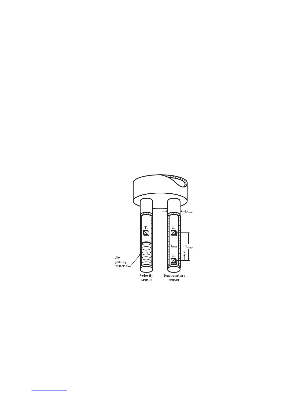
Sierra’s unique QuadraTherm™ sensor probe is responsible for the unsurpassed accuracy,
ruggedness, and reliability of Sierra industrial flow meters. The immersible sensor
consists of four sensing elements–a velocity sensor, a temperature sensor, and two
stem conduction sensors that measure heat lost to the outside.
When power is applied to the flow meter, the transducer electronics heats the velocity
sensor to a constant temperature differential above the gas temperature and measures
the cooling effect of the gas flow. The electrical power required to maintain a constant
temperature differential is directly proportional to the gas mass flow rate. The two
stem conduction sensors ensure that any heat lost is due to this cooling effect, and not
due to conduction to the outside.
The velocity sensor is a reference-grade platinum resistance temperature detector (RTD).
The platinum RTD wire is wound on a rugged ceramic mandrel for strength and stability.
The temperature sensor is clad in 316 stainless steel. The velocity sensor is clad in a
Pt/Ir Alloy.
www.sierrainstruments.com/thermalprincipal
Figure 1-1:640i & 780i Series Sensor Assembly
8

iTherm™ Electronics Features
iTherm™ Dial-A-Gas™ Technology
Select gas to be measured
iTherm™ Dial-A-Pipe™ Technology
Set-up pipe dimensions
Units
Select units for mass flow, temperature, and pressure
User Full Scale Flow Rate
Field-configure from 50% to 100% of the factory full scale setting
Alarms
Program high & low or window alarm limits independently for mass flow,
temperature, pressure and totalizer (select one)
MeterTune™ (Span Adjust)
Change the calibration correction factor to compensate for flow profile disturbances or
specific application conditions. The MeterTune™ (span adjust) is a multiplication factor
applied to the flow signal
Dual Output Signals
Two 4-20mA separate linear output signals proportional to flow and
temperature. Optional 4-20mA proportional to pressure if pressure option
selected.
Totalizer
Set up totalizer pulse output
Set Standard Conditions
Chose between, normal, standard and other
Set Password
Set user password
Set Low Flow Cut-off
Force flow to zero at a specified flow rate
View Tag Number
View assigned tag number
Set Language
Set language for display
9

View Communications Protocol Parameters
View communications settings: 38,400 Baud rate, no parity, 8 data bits, and 1
stop Bit
ValidCal™ Diagnostics
Review minimum, maximum flow, temperature and pressure and other
diagnostics
Enclosure Options
Flow meter electronics are available mounted directly to the flow body, or remotely
mounted up to 200 feet (60 meters) away. The electronics’ housing may be used indoors
or outdoors.
Display options include a programmable LCD displaying mass flow, temperature,
pressure, totalized flow, Dial-A-Gas, Dial-A-Pipe, MeterTune, and user full scale along
with alarm, reference conditions, serial numbers and tag number. Local operation and reconfiguration is accomplished using the push buttons on the device. Electronics include
non-volatile memory that stores all configuration information. The memory allows the
flow meter to function immediately upon power up, or after an interruption in power.
10

Warning!
Agency approval for hazardous location installations varies between flow meter models. Consult the flow meter
nameplate for specific flow
meter approvals before any
hazardous location installation.
Chapter 2: Installation & Wiring
Installation Overview
The 640i and 780i are easy to set up in the field. The flow meter should be inserted
to the centerline of the pipe.
When selecting an installation site, make sure that:
1. Line pressure and temperature will not exceed the flow meter
rating. If ambient temperature exceeds 50°C, remove flow
meter to a cooler area.
2. The location meets the required minimum number of pipe
diameters upstream and downstream of the sensor head
(see Figure 2-1 on the next page)
3. Safe and convenient access with adequate clearance.
.
Also, verify the meter is located where the gas is clean and
dry.
4. Verify that the cable entry into the instrument meets the
FM standard (if required).
5. For remote installations, verify the supplied cable length is
sufficient to connect the flow meter sensor to the remote
electronics. (Do not extend or shorten the supplied cable
between the probe and the electronics.)
6. Also, before installation check your flow system for
anomalies such as:
Leaks
Valves or restrictions in the flow path that could
create disturbances in the flow profile that might
cause unexpected flow rate indications
Heaters that might cause rapid excursions in
the measured temperature
11
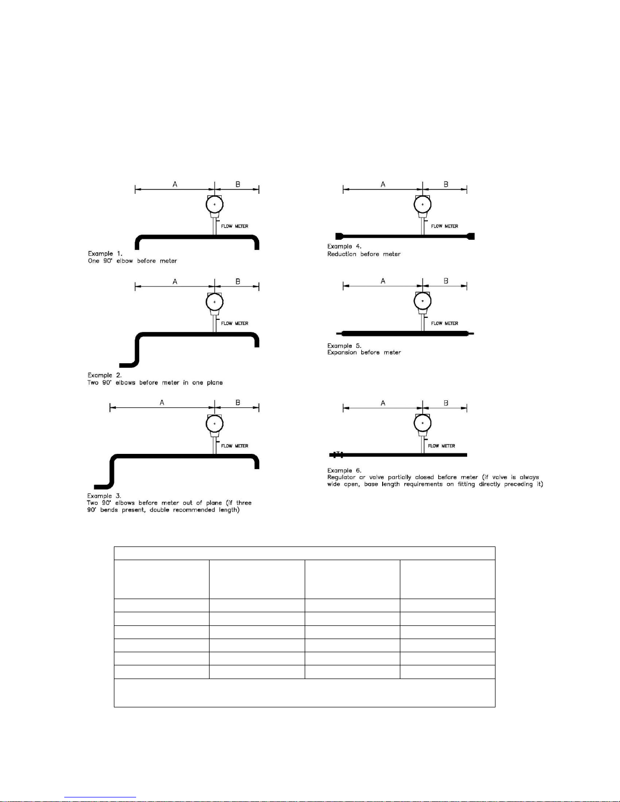
Unobstructed Flow Requirements
640i and 780i Straight Run Requirements
Piping Condition
Example
A-Upstream 640i
Insertion
(1)
A-Upstream 780i
Inline with Flow
Conditioning
(1)
B-Downstream
(2)
1
15D
1D
0D
2
20D
3D
0D 3 40D
3D
0D
4
15D
3D
0D
5
30D
3D
0D 6 40D
5D
0D
Notes: (1) Number of diameters (D) of straight pipe required between upstream disturbance and the flow meter (2) Number of
diameters (D) of straight pipe required downstream of the
flow meter
Select an installation site that will minimize possible distortion in the flow
profile. Valves, elbows, control valves and other piping components may cause
flow disturbances. Check your specific piping condition against the examples
shown below. In order to achieve accurate and repeatable performance install the
flow meter using the recommended number of straight run pipe diameters
upstream and downstream of the sensor.
Figure 2-1: Recommended Pipe Length Requirements for Installation
12
Caution!
When using toxic or corrosive gases, purge the
line with inert gas for a
minimum of four hours
at full gas flow before
installing the flow meter.
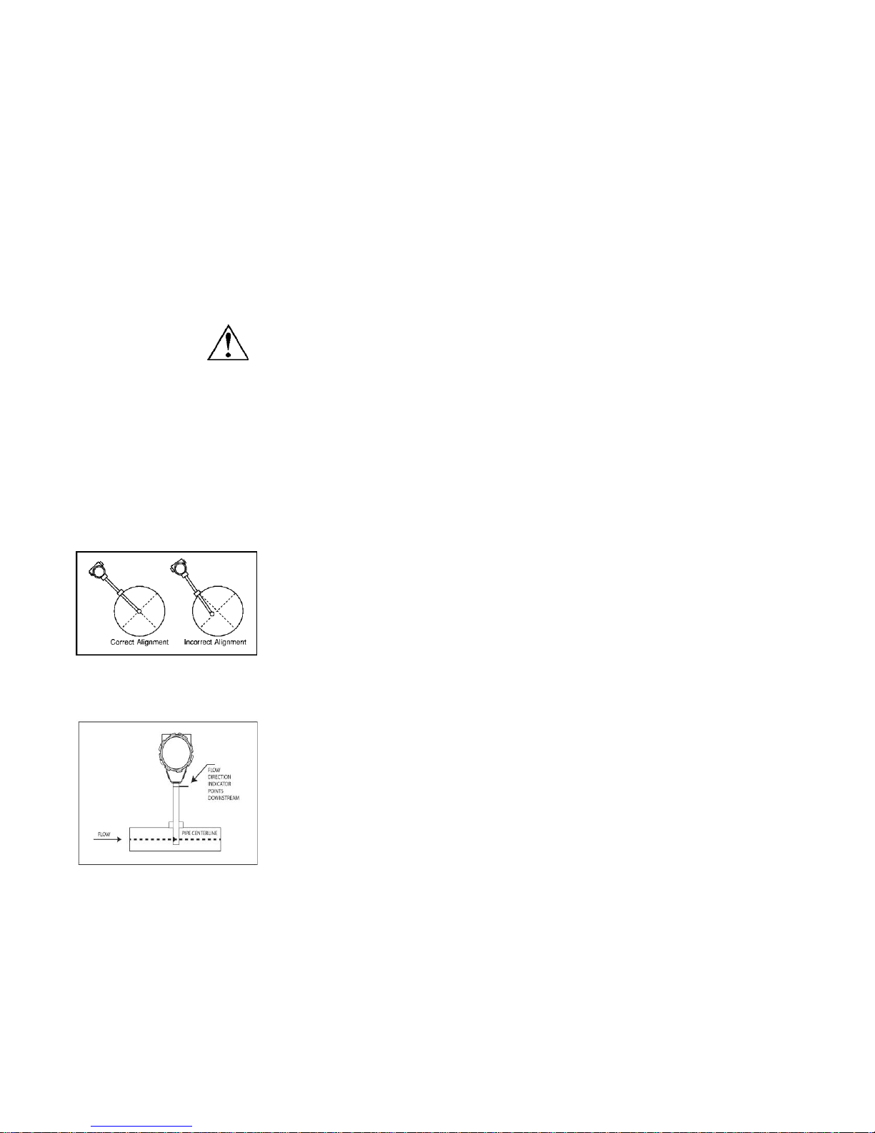
Installing the Flow Meter
NOTE: Probe may enter the pipe
from any direction as long as the
tips are in the center.
When positioning the flow meter, refer to the flow direction indicator attached to the probe. For proper operation, install the meter with the flow
direction indicator pointing downstream in the direction of flow.
Installing the meter opposite this direction will result in inaccurate flow
measurement
Cold Tap Installation
1. Confirm that the installation site meets the minimum upstream and
downstream pipe diameter requirements shown in Figure 2-1.
2. Turn off the flow of process gas. Verify that the line is not pres-
surized.
3. Use a cutting torch or sharp cutting tool to tap into the pipe. The pipe
opening must be at least 0.78 inches in diameter. (Do not attempt to
insert the sensor probe through a smaller hole.)
4. Remove all burrs from the tap. Rough edges may cause flow profile
distortions that could affect flow meter accuracy. Also, obstructions
could damage the sensor assembly when inserting into the pipe.
5. Mount the compression or flange fitting on the pipe. Make sure this
connection is within ±5° perpendicular to the pipe centerline as
shown at left.
6. When installed, cap the fitting. Run a static pressure check on the
connection. If pressure loss or leaks are detected, repair the connection and re-test.
7. Insert the sensor probe through the compression or flange fitting into the
pipe. The correct insertion depth places the centerline of the sensor
access hole in the probe at the pipe’s centerline.
8. Align the sensor head using the flow direction indicator. Adjust the
indicator parallel to the pipe pointing downstream in the direction of
flow.
9. Tighten the fitting to lock the flow meter in position. (When a compression fitting is tightened, the position is permanent unless using
Teflon ferrules.)
13

Caution!
All flow meter connec-
tions, isolation valves
and fittings for hot tap-
ping must have the same
or higher pressure rating
as the main pipeline.
Warning!
Hot tapping must be
performed by a trained
professional. U.S. regula-
tions often require a hot
tap permit. The manufac-
turer of the hot tap
equipment and/or the
contractor performing the
hot tap is responsible for
providing proof of such a
Hot Tap Installation
When positioning the flow meter, refer to the flow direction indicator attached to the probe. For proper operation, install the meter with the flow
direction indicator pointing downstream in the direction of flow. Installing the meter opposite this direction will result in inaccurate flow measurement. Low pressure hot taps cannot exceed 150 psia (10 bara) maximum. High pressure hot taps cannot exceed 1000 psia (70 bara) maximum. Make sure the pipe pressure does not exceed these limits before
beginning this procedure.
1. Confirm that the installation site meets the minimum upstream and
downstream pipe diameter requirements shown in Figure 2-1.
2. Calculate the flow meter insertion depth as shown in Figure 2-2 for a
low pressure tap or Figure 2-3 for a high pressure tap.
3. Weld the process connection on the pipe. Make sure the process
connection is within ± 5° perpendicular to the pipe centerline (see
previous page). The pipe opening must be at least 0.88 inches (22
mm) in diameter.
4. Bolt an isolation valve on the process connection. The valve’s full
5. Hot tap the pipe.
6. Close the isolation valve. Run a static pressure. If pressure loss or
7. Insert the sensor probe through the isolation valve into the pipe with
8. Tighten the fittings to lock the flow meter in position.
open bore must be at least 0.88 inches (22 mm) in diameter.
leaks are detected, repair the connection and re-test.
the flow direction indicator parallel to the pipe pointing downstream
in the direction of flow. The correct insertion depth places the sensor
at the pipe’s centerline. Do not force into the pipe.
14
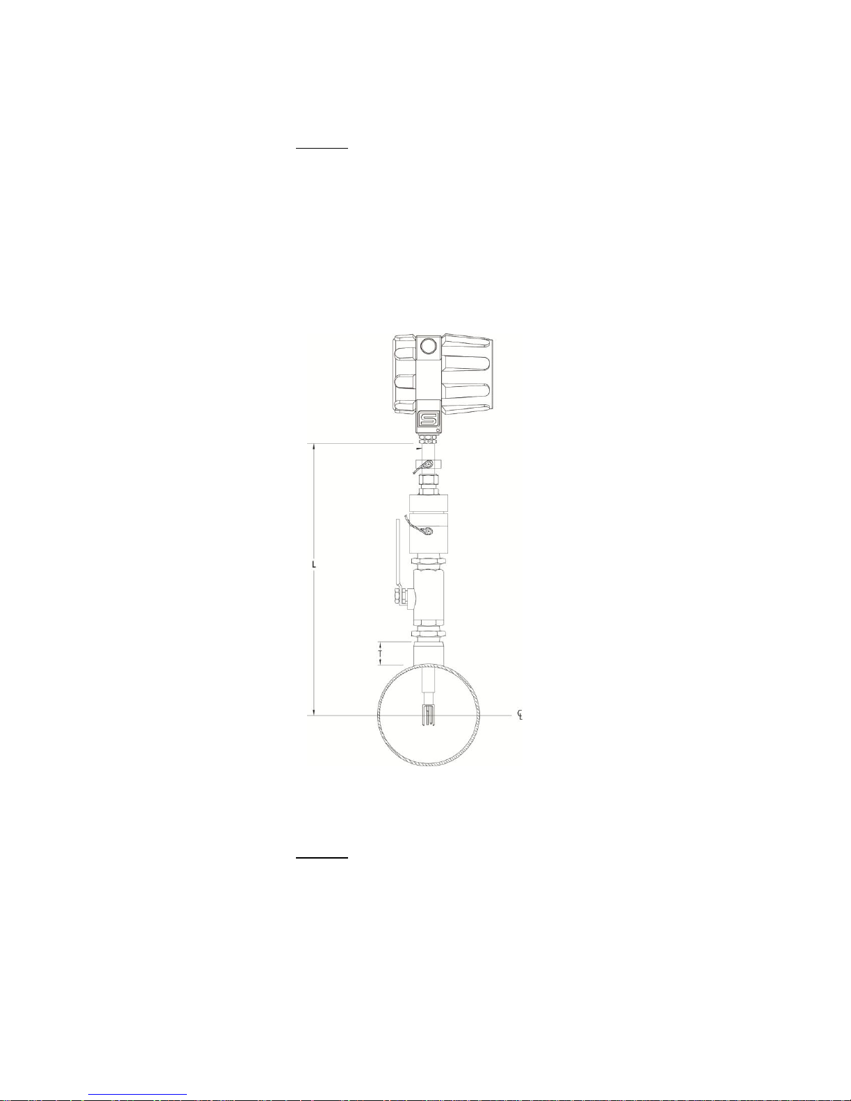
Calculating Insertion Depth for a Low Pressure Tap
Variables
L = Nominal probe length
D = Duct O.D.
C = Duct I.D.
T = Height of “Threadolet” or customer provided “Weldolet”
Formula
L ≥ 12 + D/2 + T
L must be equal or greater than 12 inches plus the height of the
“Threadolet” plus half the duct O.D.
(All dimensions in inches.)
Calculating Insertion Depth for a High Pressure Tap
Figure 2-2: Low Pressure Tap Insertion Depth
Variables
S = Distance from face of mounting flange to outside of duct
D = Duct O.D.
P = Minimum probe length
T = Minimum probe travel
R = Allowable probe travel
IN = Inserted position (marker location)
RE = Retracted position (marker location)
15
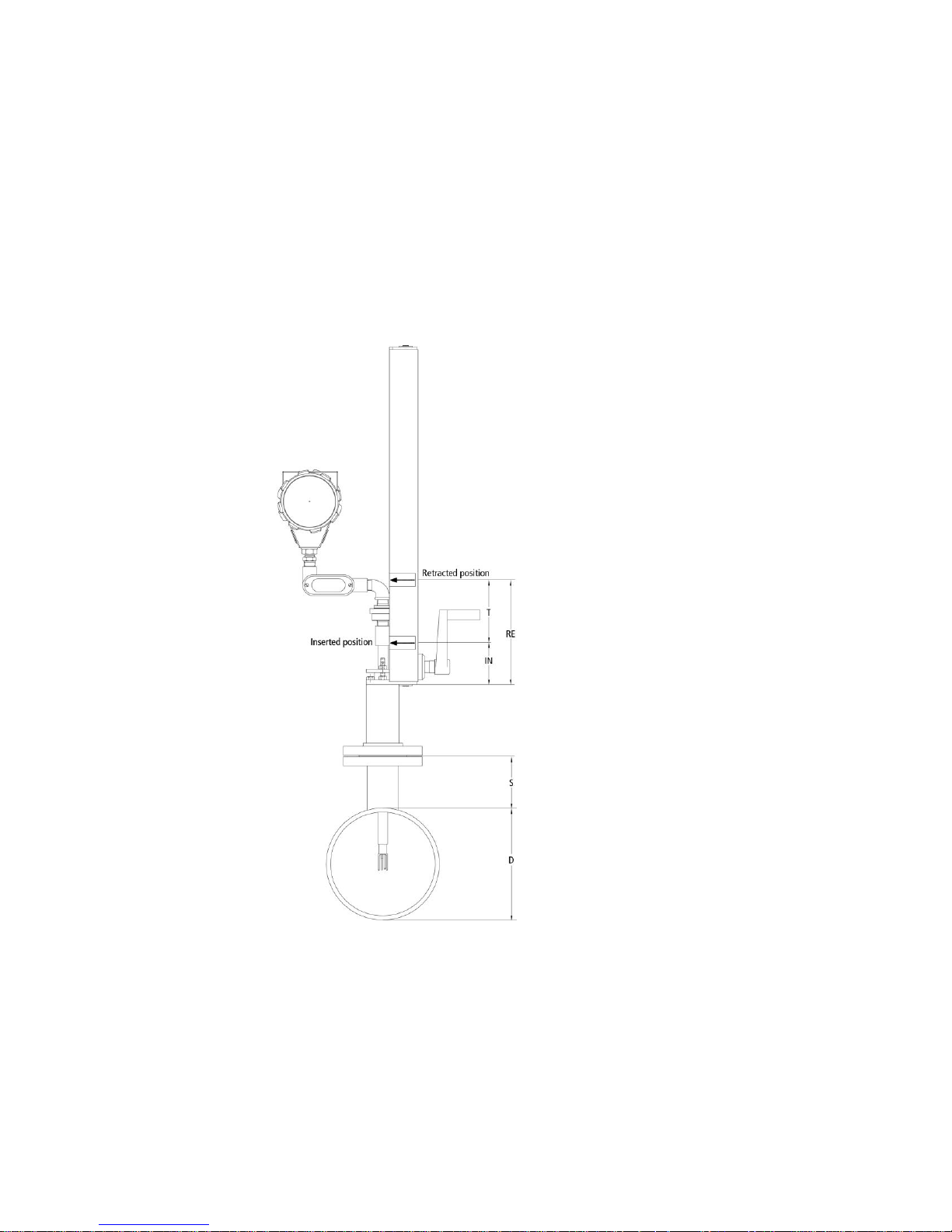
Formulas
1) P = D/2 + S + 6.75
2) T = D/2 + 0.54
3) R = 28.2 – [actual probe length – S – (D/2)]
4) IN = (actual probe length + 2) – (5.5 + S + D/2)
5) RE = IN + T
(All dimensions in inches.)
(minimum probe length–use next longer whole number length probe)
(must be greater than or equal to T)
Figure 2-3. High Pressure Tap Insertion Depth
16
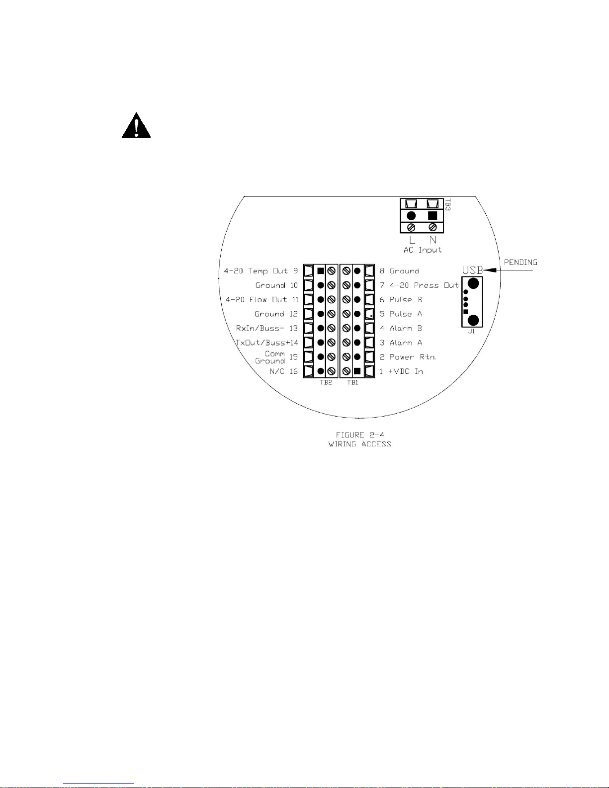
Figure 2-4. Wiring Access
To avoid potential electric
shock, follow National Elec-
tric Code safety practices or
your local code when wiring
this unit to a power source
and to peripheral devices.
Failure to do so could result
in injury or death. All AC
power connections must be
in accordance with pub-
lished CE directives.
Warning!
Wiring Connections
Use the terminal blocks located inside the cap of the flow meter
enclosure for all wiring connections. Make sure to observe all CE
compliance requirements for AC wiring connections given on the next
page.
17
Warning!
All wiring procedures must
be performed with the
power Off.
Caution!
The AC wire insulation tem-
perature rating must meet or
exceed 80 °C (176°F).
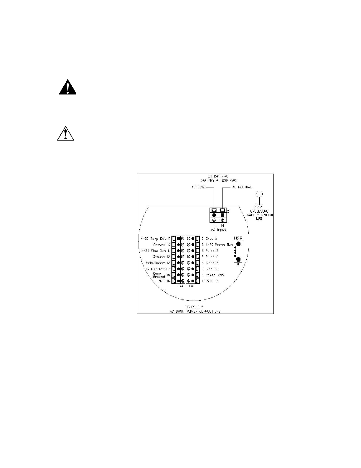
Figure 2-5: AC Input Power Connections
Input Power Wiring
AC Power Wiring
The AC power wire size must be 26 to 16 AWG with the wire stripped 1/4
inch (6 mm). Connect 100 to 240 VAC (0.4 Amps RMS at 230 VAC) to the
Neutral and Line terminals on the terminal block. Connect the ground wire
to the safety ground lug. Torque all connections to 4.43 to 5.31 in-lbs (0.5
to 0.6 Nm).
The Hazardous-Area enclosure has two separate conduit entries to maintain
separation between AC input power and output signal wiring. To
eliminate the possibility of noise interference, use a separate cable entry
for the AC power and signal lines.
18
Warning!
All wiring procedures must
be performed with the
power Off.
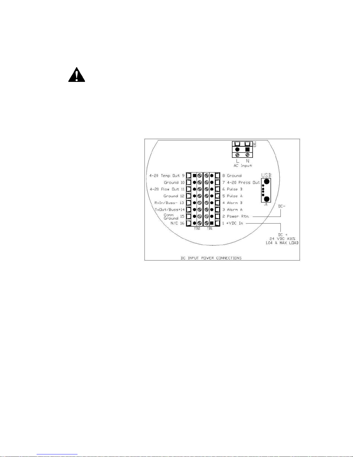
Figure 2-6: DC Input Power Connections
DC Power Wiring
The DC power wire size must be 26 to 16 AWG with the wire stripped 1/4
inch (6 mm). Connect 24 VDC +/- 10% (1.04A load, maximum) to the
terminals marked on the terminal block. Connect the Earth ground wire to
the safety ground log. Torque all connections to 4.43 to 5.31 in-lbs (0.5 to
0.6 Nm).
If conduit seals are used, they must be installed within 18 inches of the
enclosure.
19
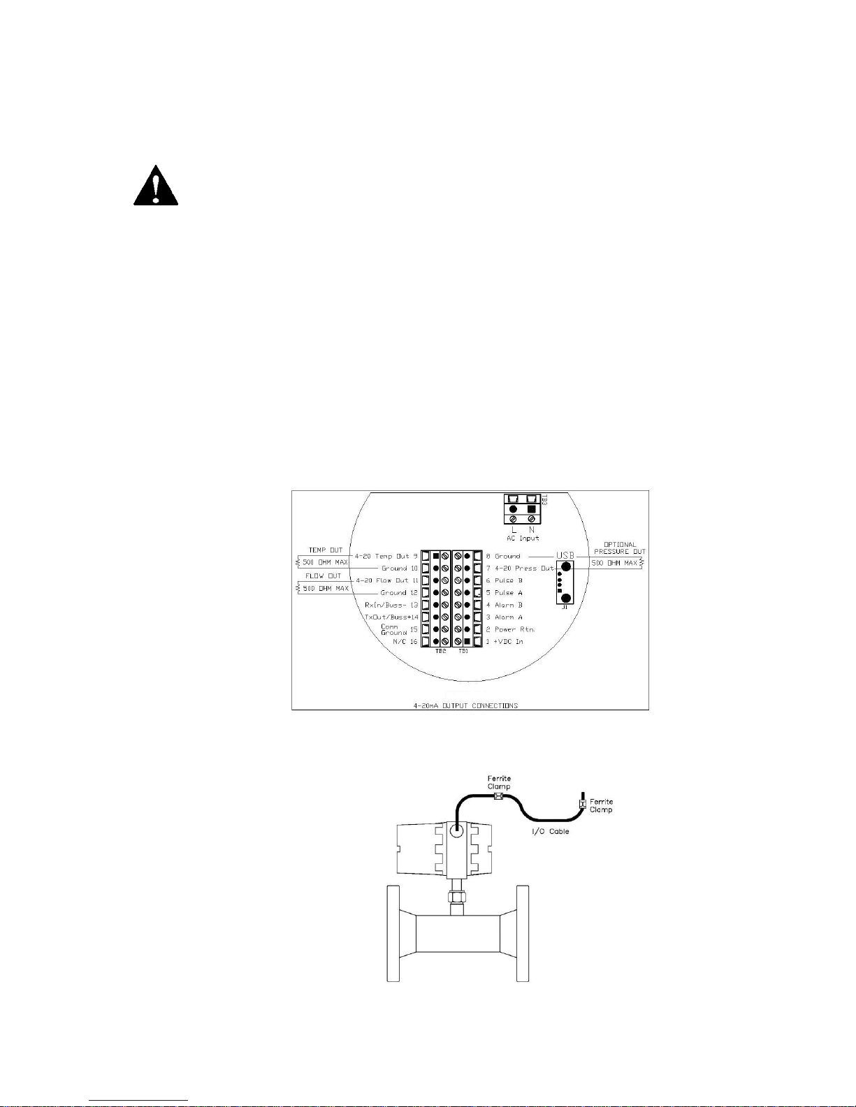
Figure 2-7: 4-20mA Output Connections
Warning!
Do not externally power
the 4-20mA output loop.
It is a self-powered
loop.
Figure: 2-8 Ferrite Installation (Ferrite not required for conduit)
Output Signal Wiring
Output signal cable should be completely screened with a 100% shield.
You must use metal cable glands that provide cable screen clamping. The
cable screen should be connected to the gland and shielded at both ends
over 360 degrees. The shield should be terminated to an earth ground. For
all installations not using metal conduit two ferrite beads should be
added, one on each end of the I/O cable. This is to maintain CE related
EMI/RFI protection. Good quality (Highest impedance at 100MHz)
Broadband ferrites should be used, a solid cylindrical ferrite
(recommended) usually has better performance than a clamp on ferrite.
The ferrites should fit as tight as possible to the OD of your cable.
All QuadraTherm 640i/780i Series flow meters are equipped with calibrated 4-20
mA output signals for both T and P, with an optional 4-20 MA output for pressure.
4-20 mA Output Wiring
The 4-20 mA current loop output is non-isolated. Max load 500 ohms
20
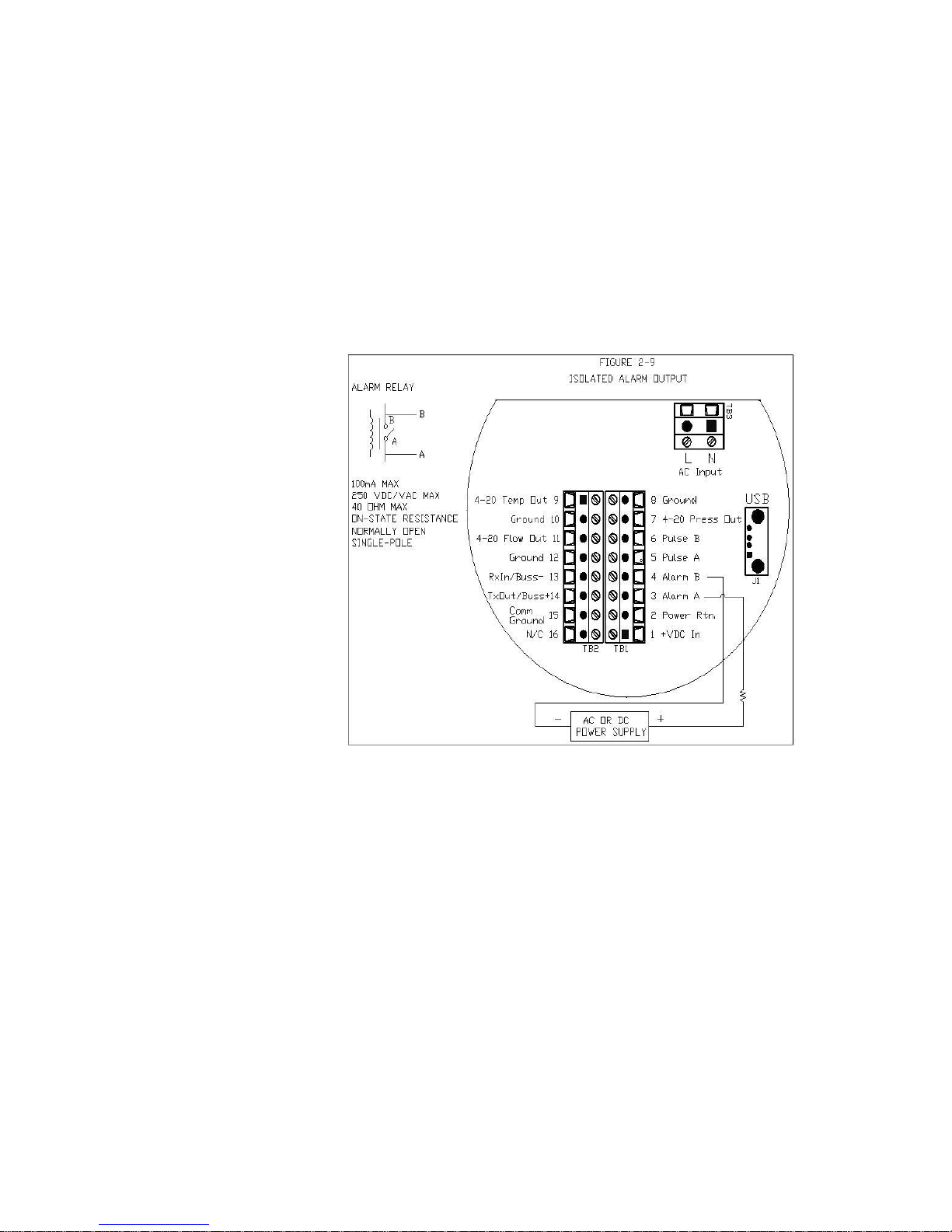
Alarm Output Wiring
Figure 2-9: AC or DC Power Supply
One alarm output contact is included on the flow meter terminal block.
The alarm output is driven by an optical relay that is normally-open
single-pole.
The relay is isolated and requires a separate power supply (isolated) the
voltage of the alarm output is the same as the voltage supplied to the
circuit.
To use an external power supply for an isolated alarm output, connect
as shown in Figure 2-8. You may set low, high or window alarms for
temperature, pressure, totalizer or mass flow
.
21
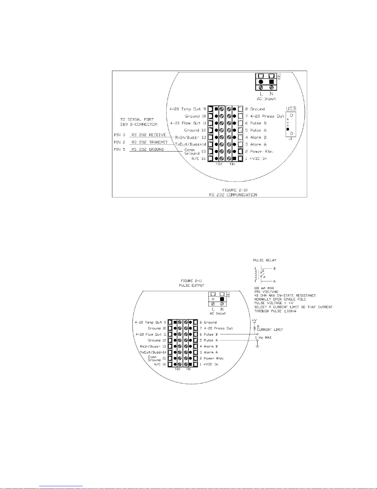
Figure 2-11:Pulse Output
Figure 2-10: RS-232 Communication
RS-232 Wiring
RS-232 provides serial communication. Wire per figure 2-10.
Pulse Output
QuadraTherm provides an adjustable pulse output with a maximum of 1 Hz. Wire per
figure 2-11 below.
22
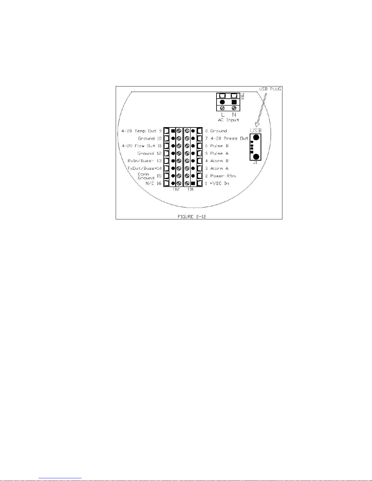
USB Output
Figure 2-12: USB Output (pending)
If supplied, plug your USB adapter into J1, per figure 2-12 (USB pending).
23
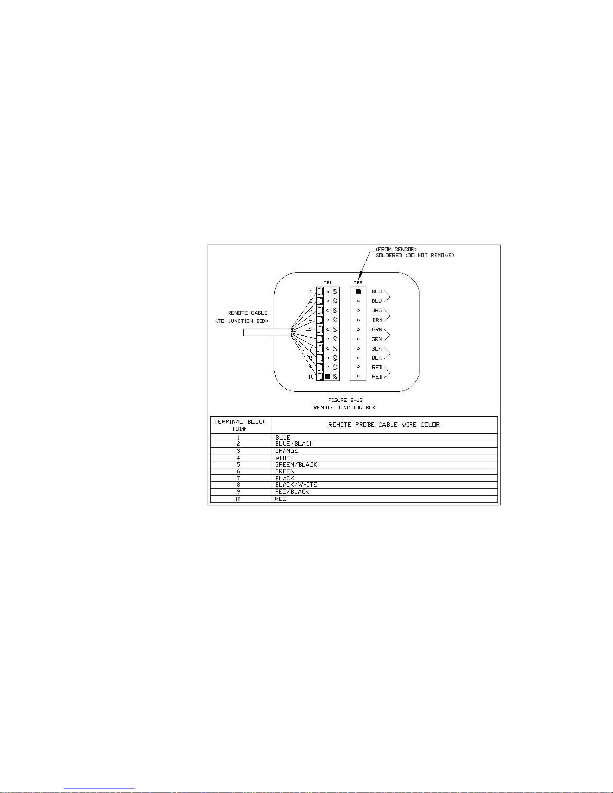
Figure 2-13: Remote Junction Box
Remote Sensor Wiring
When connecting the sensor probe to a remotely mounted flow meter enclosure, use only factory supplied cables. When connecting more than
one meter, do not intermix the sensor probes and electronics. The electronics, sensor probes and interconnecting cables supplied by Sierra Instruments are calibrated as a complete precision mass flow circuit.
To make wiring connections from a sensor probe junction box to a
remotely mounted enclosure, see Figure 2-13.
24

Chapter 3: Operation & Programming
General Navigation
In general terms, the menu system consists of a main menu, the set-up menu, a submenu to program each item in the set-up menu, and a series of data entry or pulldown screens with to enter set-up data for each parameter.
Menus may be adjusted using the six buttons on the front of the unit: up , down ,
left , right , enter and escape/cancel , or by using the Smart Interface Program
(SIP) software provided free with the instrument.
Pressing the left button will move the menu selection to the left, or the data entry
field to the left if updating a menu value.
Pressing the right button will move the menu selection to the right, or the data entry
field to the right if updating a menu value.
Pressing the up button will move the menu selection up, or increment the data entry
field if you’re updating a menu value.
For example, if you’re updating a value, and that value is currently set to “0”, pressing
the up key will increase the value to the next logical value, in our example it would
be “1”, then “2”, “3” and so on to “9” then back to “0”
Pressing the down button will move the menu selection down, or decrement the data
entry field if you’re updating a menu value.
For example, if you’re updating a value, and that value is currently set to “9”, pressing
the down key will decrease the value to the next logical value, in our example it
would be “8”, then “7”, “6” and so on to “0” then back to “9”
Pressing the enter key accepts the current value.
Pressing the escape/cancel key returns to the last previous menu, and if you’re
currently editing a value, will cancel any changes you’ve made.
Note: The screen data “flashes” to show that you are actively editing. Pressing
the enter key permanently writes the data to the meters memory.
25
640i/780i
V1.0.X
Serial
1234XXXX
Full Scale
100.00 SCFM
Dial-A-Gas
Carbon Dioxide
Tag
1234XXXX
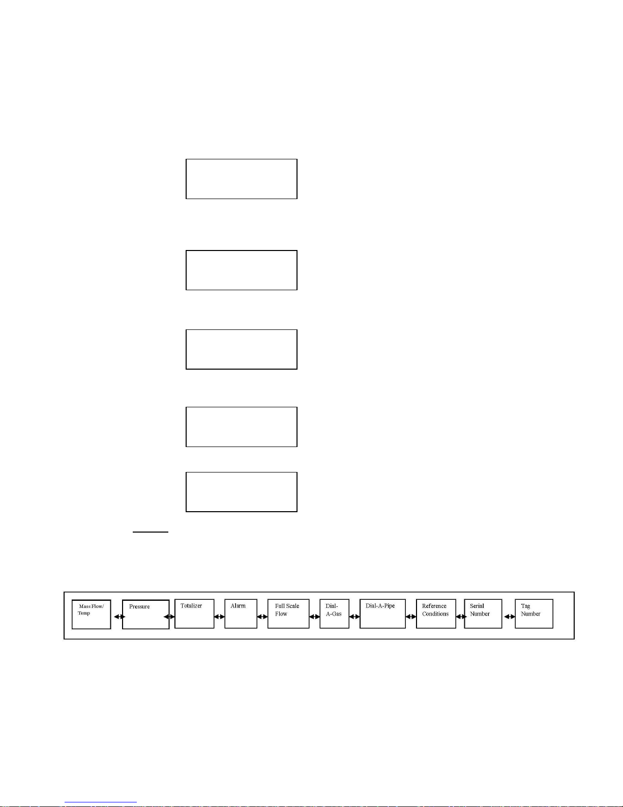
Start-up Routine
Then the meter is first powered up, it will cycle through set-up data. See an example
below of the type of screens you will see.
1. Product Name and Firmware Version. Left is main PCA / right is display PCA
2. Serial Number
3. Full Scale
4. Gas
5. Tag Number
NOTE: All of these values are also displayed on the provided SIP (Smart Interface
Program) software.
Level 1: Main Menu
Table 3-1: Main Menu Level 1
26
 Loading...