

Page 1
Installation Instructions
Model XLS-MSE2(R)-ADPT
Adapter Kit
INTRODUCTION Use the Model XLS-MSE2(R)-ADPT Adapter Kit from Siemens Industry, Inc., to
upgrade existing MXL Systems installed in Model MSE-2(R) backboxes to FireFinderXLS/Desigo Fire Safety Modular/Cerberus PRO Modular Systems. The XLS-MSE2(R)ADPT Adapter Kit consists of an adapter plate, inner door and outer door. The XLSMSE2-ADPT (S54430-C7-A1) inner and outer doors are black; the XLS-MSE2R-ADPT
(S54430-C7-A2) inner door is black and outer door is red. The XLS-MSE2-ADPT and
the XLS-MSE2R-ADPT are identical in all other ways and will be referred to in the
remainder of this document as XLS-MSE2-ADPT.
The adapter plate installs over the existing studs in an MSE-2(R) backbox with the
#1/4 x 20 hex flange nuts supplied and provides four studs on which to mount one
CAB-MP mounting plate (P/N 500-633012) and four studs on which to mount one
PTB (P/N 500-033390).
The inner door has an opening in it for the installation of an operator interface and
other modules. There are eight threaded studs around each opening on the inner
door. These threaded studs allow equipment installation on the door. The equipment
is secured by #10-32 nuts. The inner door is permanently hinged right, is attached to
the backbox by screws, and is secured to the backbox by swell-action latches.
The XLS-MSE2(R)-ADPT is for indoor use only in dry environments.
With this conversion, the maximum battery set that can be used in the backbox is 33
AH (model BTX-1). If larger batteries are required, use either a BB-55 or CAB-BATT
battery box.
When converting an MXL to an XLS/Desigo Fire Safety Modular/Cerberus PRO
Modular system, it may be necessary to use the XLS-EXT-CABLE-PKG (S54430-K1A1). This kit includes a 58 inch 60-pin Data Bus cable, a 58 inch 6-pin CAN Bus cable
and a 20 inch 12AWG ground wire.
To convert an MSE-2(R) backbox from an MXL System to an XLS/Desigo Fire Safety
Modular/Cerberus PRO Modular component system, you must first disassemble the
MXL and then assemble the XLS/Desigo Fire Safety Modular/Cerberus PRO Modular.
This two-part procedure is described in detail below.
DISASSEMBLY OF MXL SYSTEM
Remove all system power, first battery and then AC.
A6V10328634_en--_b
1. Remove and discard the outer door and the hardware used to secure it in
place.
2. Disconnect and remove the modules from the inner door.
Building Building
Building
Building Building
Siemens Siemens
Siemens
Siemens Siemens
TT
ecec
hnologies Dihnologies Di
T
ec
hnologies Di
TT
ecec
hnologies Dihnologies Di
IndustryIndustry
Industry
IndustryIndustry
visionvision
vision
visionvision
,,
Inc. Inc.
,
Inc.
,,
Inc. Inc.
Page 2
3. Remove all modules from the backbox, making sure to mark all wires.
4. Remove the MPS power supply and batteries from the backbox. Save the
mounting hardware for later use.
ASSEMBLY OF XLS/DESIGO FIRE SAFETY MODULAR/CERBERUS PRO MODULAR SYSTEM
The three parts of the XLS-MSE2-ADPT are installed separately. The adapter plate is
installed first, followed by the inner door and then the outer door.
Adapter Plate The XLS-MSE2-ADPT adapter plate has holes in it that fit over the studs in the MSE-2
backbox in only one way.
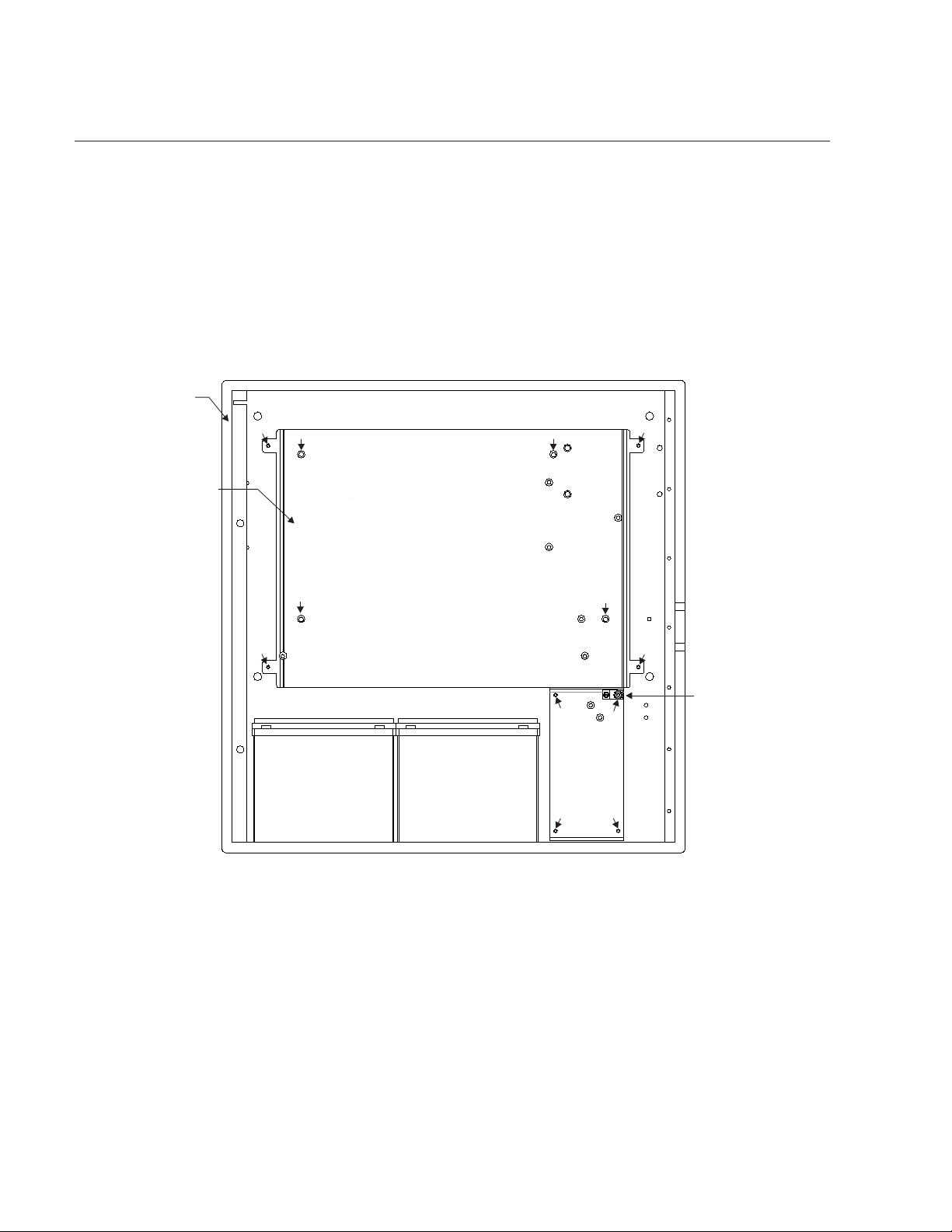
1. Place the XLS-MSE2-ADPT over the studs in the backbox and secure it in
place with the four #1-4 x 20 hex flange locknuts supplied in the locations
marked “A” in Figure 1.
MSE-2
BACKBOX
“B”
XLS-MSE2(R)-ADPT
ADAPTER PLATE
“B”
“A”
“A”
“B”
“A”
“C”
“C”
“A”
“D”
“C”
“B”
GROUND LUG
(THIS LUG IS FOR
GROUNDING THE
AC INPUT)
REMOVE GROUND
LUG BEFORE
MOUNTING THE PTB.
AFTER INSTALLING
THE PTB, BE SURE
TO REINSTALL THE
GROUND LUG.
Figure 1
Installing the XLS-MSE2-ADPT Adapter Plate in the MSE-2 Backbox
2. One CAB-MP can be mounted on the XLS-MSE2-ADPT using the studs
marked “B” in Figure 1.
3. Install the required CC-5/CC-2 system cardcage(s), PSC-12 power supply,
optional PSX-12 power supply extender and PTB power termination board
after careful consideration of NEC Article 760 for separation of power
limited and non-powered limited wiring. Use the hardware provided with
those modules to mount them to the CAB-MP mounting plate. Refer to the
CC-5/CC-2 Installation Instructions, P/N 315-033035, the PSC-12 Installation
Instructions, P/N 315-033060, and the PSX-12 Installation Instructions, P/N
315-034120.
Siemens Industry, Inc.
Building Te chnologies Division
A6V10328634_en--_b2
Page 3
4. One PTB can be mounted on the XLS-MSE2-ADPT using the studs marked
“C” and “D” in Figure 1. Refer to the PTB Installation Instructions, P/N 315-
034877. The stud marked “D” is a lug for grounding the AC input. Remove
the ground lug before mounting the PTB. After installing the PTB, be sure to
reinstall the ground lug.
5. There is room in the bottom of the enclosure for a battery set of up to 33 AH.
6. System cards can be installed in the CC-5 cardcage, as required.
Install the Inner Door Install the inner door by following the steps listed below.
1. Place two of the four #8-32x5/16 screws provided in the top and bottom
holes on the right-hand side of the backbox.
2. Tighten the screws just a few turns leaving a 1/8-inch gap between the
head of the screws and the backbox.
3. Slide the inner door into position under the screws.
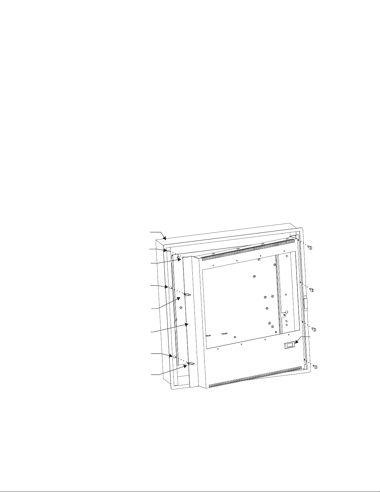
4. Make certain the flange at the left-hand top of the inner door is seated in
the slot in the backbox and the swell action latches located near the top and
bottom of the inner door are seated in their respective holes in the backbox.
(Refer to Figure 2.) Press the latches down to secure them in place, adjusting the door as needed so that it seats securely in the enclosure.
MSE-2
BACKBOX
SLOT
FLANGE
HOLE
FOR
LATCH
SWELL
ACTION
LATCH
INNER
DOOR
HOLE
FOR
LATCH
SWELL
ACTION
LATCH
Figure 2
Installing the Inner Door
8-32x5/16
SCREWS
(QTY. 4)
LOCATION OF
OPTIONAL
HTSW-1
TAMPER
SWITHCH
Siemens Industry, Inc.
Building Technologies Division
5. Insert the remaining two screws in the two holes on the right side of the
backbox to secure the inner door. Tighten all four of the screws.
A6V10328634_en--_b3
Page 4

6. Install a FCM2041-U2/-U3 on the inner door. Refer to the PMI Installation
Instructions, P/N 315-033070, the FCM2041-U2 Installation Instructions,
Document ID A6V11231623, or the FCM2041-U3 Installation Instructions,
Document ID A6V11231630, for further information.
7. Install door-mounted modules (FCM-6, LCM-8, SCM-8) as needed for
system operation.
8. Insert blank plates, as needed, in unused spaces on door and secure with
#10-32 nuts. (Refer to Table 1 and Figure 3.)
1ELBAT
SETALPROODRENNI
LEDOMNOITPIRCSEDGNITNUOM
PM-DI,6-MCFroftekcarb/etalpgnitnuoM
.MCBdna8-MCS,8-MCL
S.roodnisdutsnostnuoM
.stun23-01owthtiw
deruce
PS-DIehtsaezisemasehttresniknalB
.tekcarb/etalpgnitnuomPM-DI
.stun23-01owthtiw
.worenonodellatsnieb
deruc
eS.roodnisdutsnostnuoM
nacsPS-DIrosPM-DIruofotpU
Models LVM and FMT, one module width each, mount to the inner door. No other
modules (PSC-12/PSX-12/CC-5/CC-2) may be located behind these modules.
ID-MP
ID-SP
Figure 3
Inner Door and Plates
Install the Outer Door 1. Insert the hinge pins on the outer door in the hinges on the backbox.
2. Place the XLS system label, P/N 575-234411, Desigo Fire Safety Modular
sytem label, P/N A5Q00075144, or Cerberus PRO Modular system label, P/
N A5Q00075194, on the inside of the outer door.
Siemens Industry, Inc.
Building Te chnologies Division
A6V10328634_en--_b4
Page 5

3. A ground wire comes installed on the inside of the outer door. (Refer to
Figure 4.) Bring the free end of the ground wire through the opening at the
top left-hand side of the inner door and secure it in place on an unused stud
in the backbox with a #10-32 hex nut (user supplied).
4. Close the outer door and secure with the key latch.
OUTER
DOOR
Figure 4
Ground Wire Installation
USER SUPPLIED
#10-32 HEX NUT
GROUND WIRE
WIRE: 12 AWG
MSE-2
BACKBOX
UNUSED
STUD
WIRING In compliance with NEC Article 760, all power limited fire protective signaling
conductors must be separated a minimum of ¼ inch from all of the following wiring
located within a control panel:
• electric light
•power
• Class 1 or non-power limited fire protective signaling conductors
To meet these requirements, the following guidelines must be observed when
installing modules and wiring to this control panel.
When installing power limited field wiring, the installer must comply with NEC article
760, which states:
The fire alarm power-limited circuits are installed using Types FPL, FPLR, FPLP or
permitted substitute cable, provided these power-limited cable conductors extending
beyond the jacket are separated by a minimum of 0.25 in. (6.35 mm) or by a nonconductive sleeve or nonconductive barrier from all other conductors.
If energy limited cable or equivalent is not used within the enclosure, then the following
guidelines do not apply. In that case, be sure to follow standard wiring
Siemens Industry, Inc.
Building Technologies Division
practices.
A6V10328634_en--_b5
Page 6

Wiring Entering Enclosure Non-Power Limited Wiring
Wiring entering the enclosure from the bottom and right side of the backbox is
considered non-power limited wiring. Wiring must be in the shortest route and must
not overlap any other wiring.
Power Limited Wiring
Wiring entering the enclosure from the top and the left side of the backbox is
considered power limited. Wiring must be in the shortest route and must not overlap
any other wiring.
Use the existing lances in the backbox to dress the wires as needed to maintain
separation of power limited and non-power limited wiring.
Use the existing lances on the adapter plate to dress the wires as needed to maintain separation of power limited and non-power limited wiring.
Install Wiring The primary mains input must have a separate or dedicated circuit breaker. Wire in
accordance with local codes and Article 760 of NEC.
1. Remove the knockouts in the backbox for the entry of field wiring.
2. Pull all field wiring into the backbox. Do not dress the wiring until the
location of all the equipment is known.
3. Install the wiring from the external power source to the approximate
location of the power supply.
Siemens Industry, Inc.
Building Te chnologies Division
A6V10328634_en--_b6
Page 7

Cyber security disclaimer
Siemens products and solutions provide security functions to ensure the secure operation of building comfort,
fire safety, security management and physical security systems. The security functions on these products and
solutions are important components of a comprehensive security concept.
It is, however, necessary to implement and maintain a comprehensive, state-of-the-art security concept that is
customized to individual security needs. Such a security concept may result in additional site-specific preventive
action to ensure that the building comfort, fire safety , security management or physical security system for your
site are operated in a secure manner. These measures may include, but are not limited to, separating networks,
physically protecting system components, user awareness programs, defense in depth, etc.
For additional information on building technology security and our offerings, contact your Siemens sales or
project department. We strongly recommend customers to follow our security advisories, which provide information on the latest security threats, patches and other mitigation measures.
http://www.siemens.com/cert/en/cert-security-advisories.htm
Siemens Industry, Inc.
Building Technologies Division
A6V10328634_en--_b7
Page 8

Siemens Industry, Inc.
Building Te chnologies Division
Florham Park, NJ
Siemens Canada, Ltd.
1577 North Service Road East
Oakville, Ontario
L6H 0H6 Canada
Document ID A6V10328634_en--_b
 Loading...