

Page 1

Installation Instructions
Model XLD-1
Analog Loop Driver
OPERATION
The Model XLD-1 from Siemens Building Technologies, Inc. is an optional MXL network module that
connects XL3 analog addressable devices to the
MXL System. The module uses four consecutive
network addresses on the System. Devices
connected to the XLD-1 circuits are supervised by
the MXL Control Panel.
Each of the XLD-1 circuits supports up to 30
alarm causing, trouble causing, and supervisory
type devices, as well as intelligent output devices. Each device has its own address. The
sensitivity of any analog smoke detector is
checked and adjusted from the Control Panel.
Sensitivity, as well as other device information, is
displayed at the Control Panel. The XLD-1 also
supports the use of relay bases.
Each XLD-1 circuit can be wired in either a Class B
or Class A configuration. When using Class B, Ttapping is permitted with no loss of supervision.
The XLD-1 module has an on-board microprocessor which provides it with the ability to
function and to initiate alarm conditions even if the
Fire Safety
MXL main processor fails. The module also has
four LEDS, which can indicate alarm, trouble,
transmit, or ground fault. (Refer to Figure 1.)
For additional information on the MXL/MXLV
System, refer to the MXL/MXLV Manual, P/N
315-092036.
INSTALLATION
Remove all system power before installation, first battery and then AC. (To power up,
connect the AC first and then the battery.)
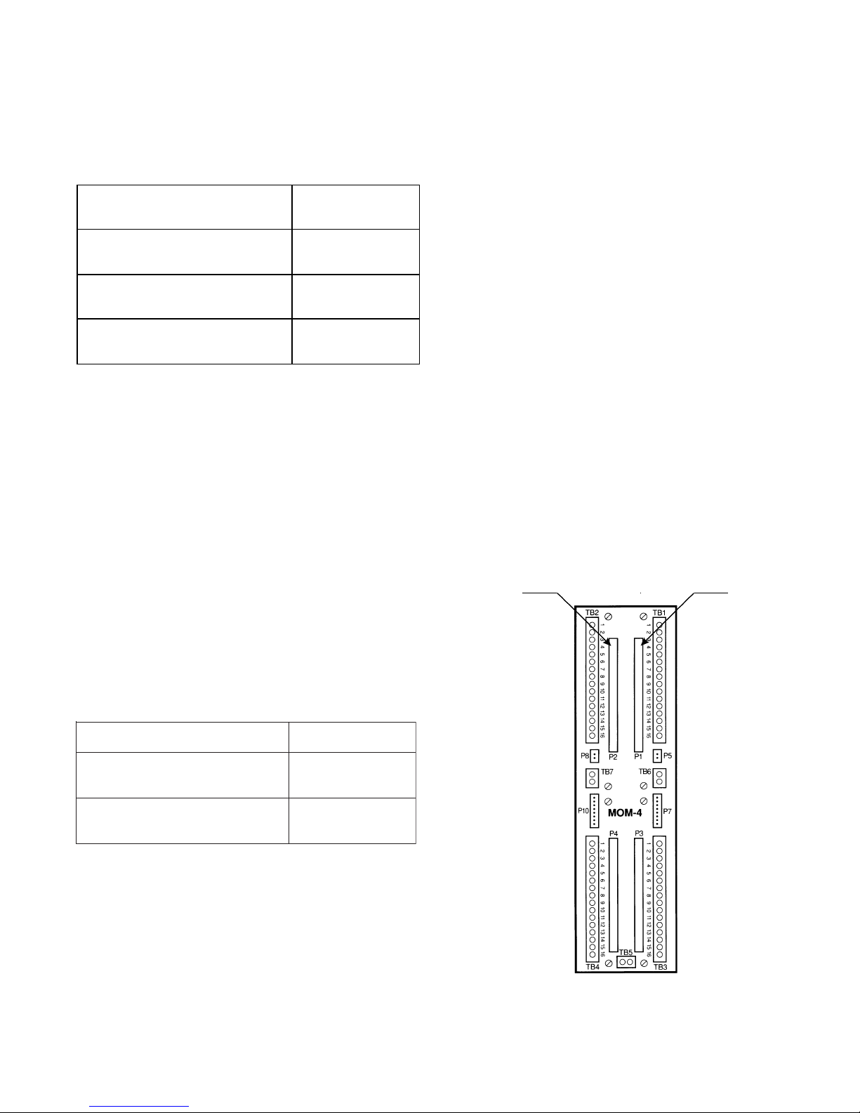
The XLD-1 installs into the MXL optional MOM-4
card cage where it plugs into one full width slot.
The XLD-1 can be installed in either of the full
width slots of the MOM-4 (See Figure 2). The slot
determines whether the device loops are available on TB1 or TB2 of the MOM-4.
Before installing the XLD-1 in the MOM-4, set the
network address using switch S1 (Refer to Figure
1 for the location of S1). Set it to the lowest of the
four corresponding addresses selected for it in the
CSG-M. (The lowest address may be odd or
Siemens Building Technologies, Inc.
8 Fernwood Road
Florham Park, New Jersey 07932
P/N 315-093385-8
Figure 1
XLD-1 Board
Siemens Building Technologies, Ltd.
2 Kenview Boulevard
Brampton, Ontario L6T 5E4 Canada
Page 2
even.) Follow the appropriate switch positions in
Table 1 on the back page to set the address (See
NOTE below).
The table below illustrates sample XLD-1 module
addresses:
XLD-1 at Module
Addresses 3, 4, 5, and 6
Loop 1
Loop 4
XLD-1 at Module
Addresses 15, 16, 17, and 18
Loop 1
Loop 4
NOTE: To open a dipswitch, press down on the side
of the dipswitch marked OPEN. To close a dipswitch,
press down on the side of the dipswitch opposite the
side marked OPEN.
To open a slide switch, push the slide to the
side opposite the side marked ON. To close a slide
switch, push the slide to the side marked ON.
Devices
003-01 to 003-30
006-01 to 006-30
Devices
015-01 to 015-30
018-01 to 018-30
After the address is set, install the XLD-1 in the
MOM-4, being sure that the module is riding in
the card guides and is firmly seated in the card
edge connector. Eliminate all troubles from each
XLD-1 before installing the next one.
Electrical connections for the four addressable
initiating zones are shown in Figure 3.
Compatible Devices
1. All circuits are power limited to NFPA 70 per
Article 760. Each detector or group of
detectors must use a 2-wire circuit of at least
18 AWG thermoplastic fixture wire enclosed
in conduit, or 18 AWG limited energy shielded
cable without conduit, if permitted by local
building codes.
2. No end of line device is required for these
initiating loops.
3. Up to 30 devices can be used per loop. See
the Compatibility Table for the XLD-1 for a
list of compatible devices. Use any combination of those listed.
4.
The compatibility identifiers for the compatible
devices are the model numbers listed in the
Compatibility Table
5. Total circuit resistance must not exceed 100
ohms.
Maximum capacitance:
0.4uF, between loop+ and loop–
0.8uF, between loop+ and chassis
0.8uF, between loop– and chassis
6. T-tapping is not allowed on Class A loops.
FULL
WIDTH
SLOT
.
FULL
WIDTH
SLOT
Electrical Ratings
(Refer to Figure 3)
tnerruCeludoMCDV5evitcAAm0
tnerruCeludoMCDV42evitcA
tnerruCeludoMCDV42ybdnatS
Initiating circuits
28 V unfiltered full wave rectified peak (Alarm and Supervisory)
40mA max per circuit (0-30 devices in alarm)
Battery Calculations
XLD-1 Module Current: 215mA
Device Current: 1.1mA per device
+Am022
ecivedrepAm1.1
+Am022
e
civedrepAm1.1
2
Figure 2
Slots for the XLD-1
Page 3

POSITIVE AND NEGATIVE GROUND FAULT DETECTED AT <40K OHMS FOR TERMINALS 1-16.
Figure 3
XLD-1 Wiring Diagram
1-DLXROFELBATYTILIBITAPMOC
elbitapmoC
seciveD
3XA-ID
H3XA-ID
3XB-ID
H3XB-ID
P
3X-ID
H3X-ID
3X-PD
531-3X-TD
HI06/I06-DI
HAI06/AI06-DI
HBI06/BI06-DI
P
TP06/P06-DI
531-T06-DI
-ILI
HA1/A1/H1/1
HB1/B1-ILI
noitallatsnI
snoitcurtsnI
F883580-513N/P
B885680-513N/P
8-095680-513N/P
1-PLI
I
1-TPL
1-TLI
6-295680-513N/P
8-095680-513N/P
6-295680-513N/
D435380-513N/P
B785680-513N/P
A604380-513N/P
1-XSM
2-XSM
1-XAP
3-XAP
C521480-513N/P
2-782090-513N/P
2-782090-513N/P
8-095680-513N/
1-XAS
3-XAS
6-295680-513N/P
3-982090-513N/P
2-882090-513N/P
4-783590-513N/P
1-XRT
6-432390-513N/P
5-532390-513N/P
3-XRT
elbitapmoC
seciveD
noitallatsnI
snoitcurtsnI
8-495290-513N/P
8-495290-513N/P
1-633390-513N/P
02/01-ISM
B02/B01-ISM
3-309090-513N/P
7-923390-513N/P
C340381-513N/P
§
§
§
0003-XEP
§
T0003-XEP
§
§
§
D2/R2/2-IRT
§
D06/R06/06-IRT
§
§
§
D6B/R6B/6B-IRT
§
R2/D2/2-XRT
/P
P
B825880-513N
C516480-513N/P
3-855780-513N/P
C255680-513N/P
C255680-513N/P
C416480-513N/P
A197780-513N/P
5-655090-513N/
3-923290-513N/P
3-513390-513N/P
E264381-513N/P
4-876680-513N/P
A882680-513N/P
noitidEht8468LUrepdetsiL§
3
Page 4

1ELBAT
GNIMMARGORPSSERDDAKROWTEN
RDDA12345678RDDA12345678RDDA12345678RDDA12345678
000
100
200
300
400
500
600
700
800
900
010
110
210
310
410
510
610
710
810
910
020
120
220
320
420
520
620
720
820
920
030
130
230
330
430
530
630
730
830
930
040
140
240
340
440
540
640
740
840
940
050
150
250
35
0
450
550
650
750
850
950
060
160
260
360
LAGELLI
LAGELLI
LAGELLI
XXOOOOOO
OOXOOOOO
XOXOOOOO
OXXOOOOO
XXXOOOOO
OOOXOOOO
OOXOOOO
X
OXOXOOOO
XXOXOOOO
OOXXOOOO
XOXXOOOO
OXXXOOOO
XXXXOOOO
OOOOXOOO
XOOOXOOO
OXOOXOOO
XXOOXOOO
OOXOXOOO
OO
XOO
XOXOXO
OXXOXOOO
XXXOXOOO
OOOXXOOO
XOOXXOOO
OXOXXOOO
XXOXXOOO
OOXXXOOO
XOXXXOOO
OXXXXOOO
XXXXXOOO
OOOOOXOO
XOOOOXOO
OXO
OOXOO
XXOOOXOO
OOXOOXOO
XOXOOXOO
OXXOOXOO
XXXOOXOO
OOOXOXOO
XOOXOXOO
OXOXOXOO
XXOXOXOO
OOXXOXOO
XOXXOXOO
OXXXOXOO
XXXXOXOO
OOOOXXOO
XOOOXXOO
OXOOXXOO
XXOOXXOO
OOXOXXOO
XOXOXXOO
OXXOXXOO
XXXOXXOO
OOOXXXOO
XOOXXXOO
OXOXXXOO
XXOXX
OOXXXXOO
XOXXXXOO
OXXXXXOO
XXXXXXOO
460
560
660
760
860
960
070
170
270
370
470
570
670
770
870
970
080
180
280
380
480
580
680
780
880
980
090
190
290
390
490
590
690
790
890
990
001
101
201
301
401
501
601
701
801
901
011
111
211
311
411
511
611
711
811
91
1
021
121
221
321
421
521
621
721
XO
)NOro(DESOLC=X)FFOro(NEPO=O
OOOOOOXO
XOOOOOXO
OXOOOOXO
XXOOOOXO
OOXOOOXO
XOXOOOXO
OXXOOOXO
XXXOOOXO
OOOXOOXO
OOXO
XOOX
OXOXOOXO
XXOXOOXO
OOXXOOXO
XOXXOOXO
OXXXOOXO
XXXXOOXO
OOOOXOXO
XOOOXOXO
OXOOXOXO
XXOOXOXO
OOXOXOXO
XOXOXOXO
O
XXOXOXO
XXXOXOXO
OOOXXOXO
XOOXXOXO
OXOXXOXO
XXOXXOXO
OOXXXOXO
XOXXXOXO
OXXXXOXO
XXXXXOXO
OOOOOXXO
XOOOOXXO
OXOOOX
XXOOOXXO
OOXOOXXO
XOXOOXXO
OXXOOXXO
XXXOOXXO
OOOXOXXO
XOOXOXXO
OXOXOXXO
XXOXOXXO
OOXXOXXO
XOXXOXXO
OXXXOXXO
XXX
XOXXO
OOOOXXXO
XOOOXXXO
OXOOXXXO
XXOOXXXO
OOXOXXXO
XOXOXXXO
OXXOXXXO
XXXOXXXO
OOOXXXXO
XOOXXXXO
OXOXXXXO
XXOXXXXO
OOXXXXXO
XOXXXXXO
OXXXXXXO
XXXXXXXO
821
921
031
131
231
331
431
531
631
X
731
831
931
041
141
241
341
441
541
641
741
841
941
051
151
251
351
451
551
651
751
851
951
061
161
261
361
461
561
661
761
861
961
071
171
271
371
471
571
671
771
871
971
081
181
281
381
48
1
581
681
781
881
981
091
191
OX
OOOOOOOX
XOOOOOOX
OXOOOOOX
XXOOOOOX
OOXOOOOX
XOXOOOOX
OXXOOOOX
XXXOOOOX
OOOXOOOX
XOOXOOO
OXOXOOOX
XXOXOOOX
OOXXOOOX
XOXXOOOX
OXXXOOOX
XXXXOOOX
OOOOXOOX
XOOOXOOX
OXOOXOOX
XXOOXOOX
OOXOXOOX
XOXOXOOX
OXXO
XOOX
XXXOXOOX
OOOXXOOX
XOOXXOOX
OXOXXOOX
XXOXXOOX
OOXXXOOX
XOXXXOOX
OXXXXOOX
XXXXXOOX
OOOOOXOX
XOOOOXOX
OXOOOXOX
X
XOOOXOX
OOXOOXOX
XOXOOXOX
OXXOOXOX
XXXOOXOX
OOOXOXOX
XOOXOXOX
OXOXOXOX
XXOXOXOX
OOXXOXOX
XOXXOXOX
OXXXOXOX
XXXXOX
OOOOXXOX
XOOOXXOX
OXOOXXOX
XXOOXXOX
OOXOXXOX
XOXOXXOX
OXXOXXOX
XXXOXXOX
OOOXXXOX
XOOXXXOX
OXOXXXOX
XXOXXXOX
OOX
XXXOX
XOXXXXOX
OXXXXXOX
XXXXXXOX
2
291
391
491
591
691
791
891
991
002
102
202
302
402
502
602
702
802
902
012
112
212
312
X
412
512
612
712
812
912
022
122
222
322
422
522
622
722
822
922
032
132
232
332
432
532
632
732
832
932
042
142
242
342
442
542
642
742
842
94
052
152
252
352
452
552
ELLI
OOOOOOXX
XOOOOOXX
OXOOOOXX
XXOOOOXX
OOXOOOXX
XOXOOOXX
OXXOOOXX
XXXOOOXX
OOOXOOXX
XOOXOOXX
OXOOXX
OX
XXOXOOXX
OOXXOOXX
XOXXOOXX
OXXXOOXX
XXXXOOXX
OOOOXOXX
XOOOXOXX
OXOOXOXX
XXOOXOXX
OOXOXOXX
XOXOXOXX
OXXOXOX
XXXOXOXX
OOOXXOXX
XOOXXOXX
OXOXXOXX
XXOXXOXX
OOXXXOXX
XOXXXOXX
OXXXXOXX
XXXXXOXX
OOOOOXXX
XOOOOXXX
OXOOOXXX
XXOO
OXXX
OOXOOXXX
XOXOOXXX
OXXOOXXX
XXXOOXXX
OOOXOXXX
XOOXOXXX
OXOXOXXX
XXOXOXXX
OOXXOXXX
XOXXOXXX
OXXXOXXX
XXXXOXXX
O
OOOXXXX
XOOOXXXX
OXOOXXXX
XXOOXXXX
OOXOXXXX
XOXOXXXX
OXXOXXXX
XXXOXXXX
LAGELLI
LAGELLI
LAGELLI
LAGELLI
LAGELLI
LAG
LAGELLI
LAGELLI
P/N 315-093385-8
 Loading...