

Page 1
XELIBRI X8
LEVEL 2.5
REPAIR DOCUMENTATION
V 1.0
V 1.0 Page 1 of 29 ICM MP CCQ GRM
X8
Company Confidential
Copyright 2003© Siemens AG
11/03
Page 2
TABLE OF CONTENTS:
INTRODUCTION..........................................................................................................................................3
1
2 BATTERY CONNECTOR ...........................................................................................................................4
3 SIM CARD READER....................................................................................................................................8
4 SYSTEM CONNECTOR ............................................................................................................................12
5 RTC BATTERY...........................................................................................................................................17
6 LCD CONNECTOR ....................................................................................................................................22
7 ROCKER KEY LEDS .................................................................................................................................26
V 1.0 Page 2 of 29 ICM MP CCQ GRM
X8
Company Confidential
Copyright 2003© Siemens AG
11/03
Page 3
1 Introduction
The Xelibri X8 is a dual band (EGSM900/GSM1800) pendant phone with a Li-Ion battery.
There are three different colour variants: Silver Glam, Diamond Pink and Citrine.
Partnumber on IMEI label:
Xelibri X8: S30880-S9230-Axxx,
where xxx may be any number from 100, 101, 102...
This manual is intended to help you carry out repairs on level 2.5, meaning limited
component repairs. Failure highlights are documented and should be repaired in the local
workshops.
It must be noted that all repairs have to be carried out in an environment set up according to
the ESD (Electrostatic Discharge Sensitive Devices) regulations defined in international
standards.
If you have any questions regarding the repair procedures or technical questions about the
spare parts do not hesitate to contact our technical support team in Kamp-Lintfort, Germany:
Tel.: +49 2842 95 4666
Fax: +49 2842 95 4302
E-mail: st-support@siemens.com
V 1.0 Page 3 of 29 ICM MP CCQ GRM
X8
Company Confidential
Copyright 2003© Siemens AG
11/03
Page 4
2 BATTERY CONNECTOR
2.1.1
2.2 Fault Description
2.2.1 Fault Symptoms for customers:
Mobile does not switch on.
2.2.2 Fault Symptom on GSM-Tester:
This fault cannot be detected with a GSM-Tester.
2.3 Repair Documentation
2.3.1 Description of procedure:
2.3.1.1 Diagnosis
Check the battery connector visually. Watch for oxidation and dry
joints!
2.3.1.2 Repair by component change
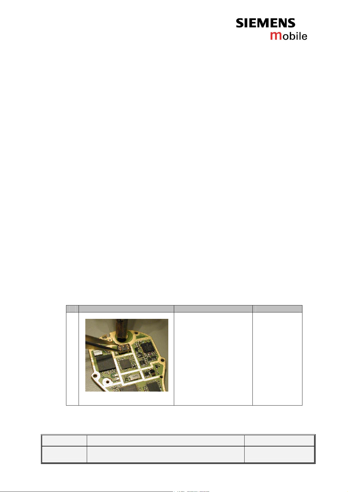
# Figure Instruction Note
1
Use a hot air blower to
remove the defective
battery connector.
Avoid excessive heat!
Watch surrounding
components!!
Figure 2-1
V 1.0 Page 4 of 29 ICM MP CCQ GRM
X8
Company Confidential
Copyright 2003© Siemens AG
11/03
Page 5
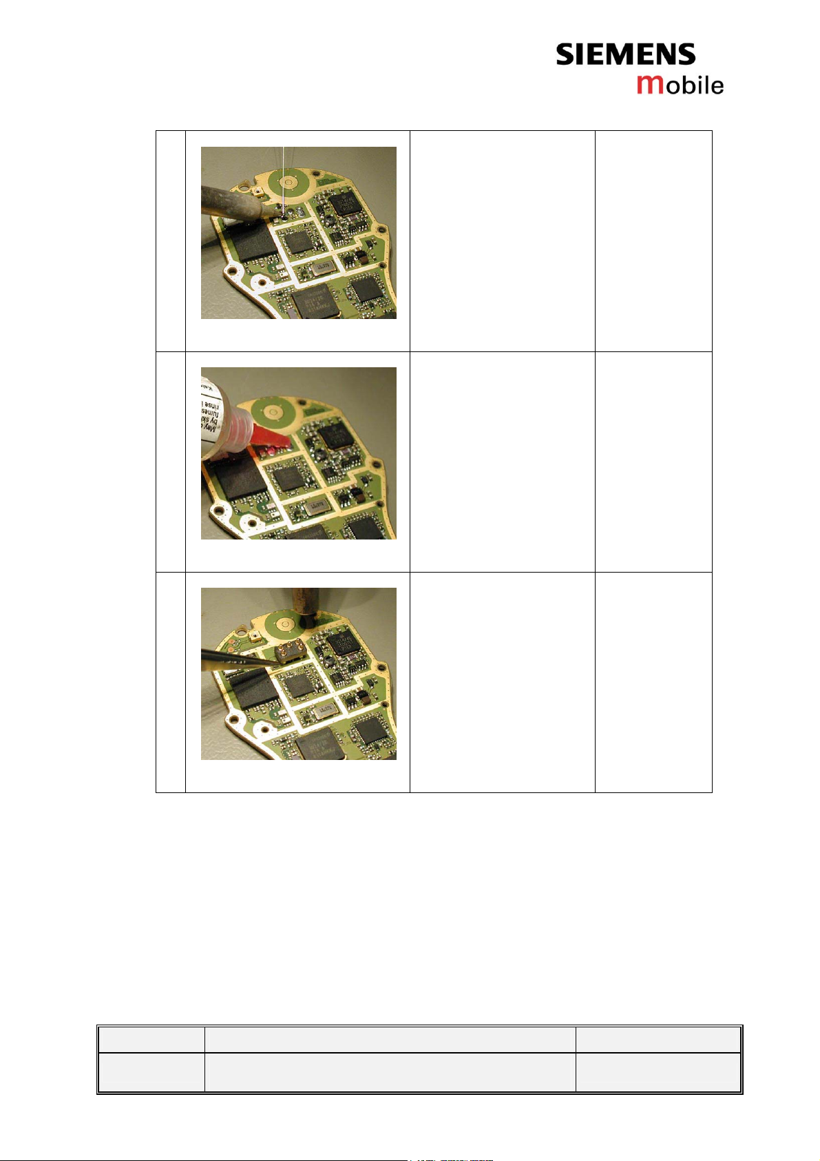
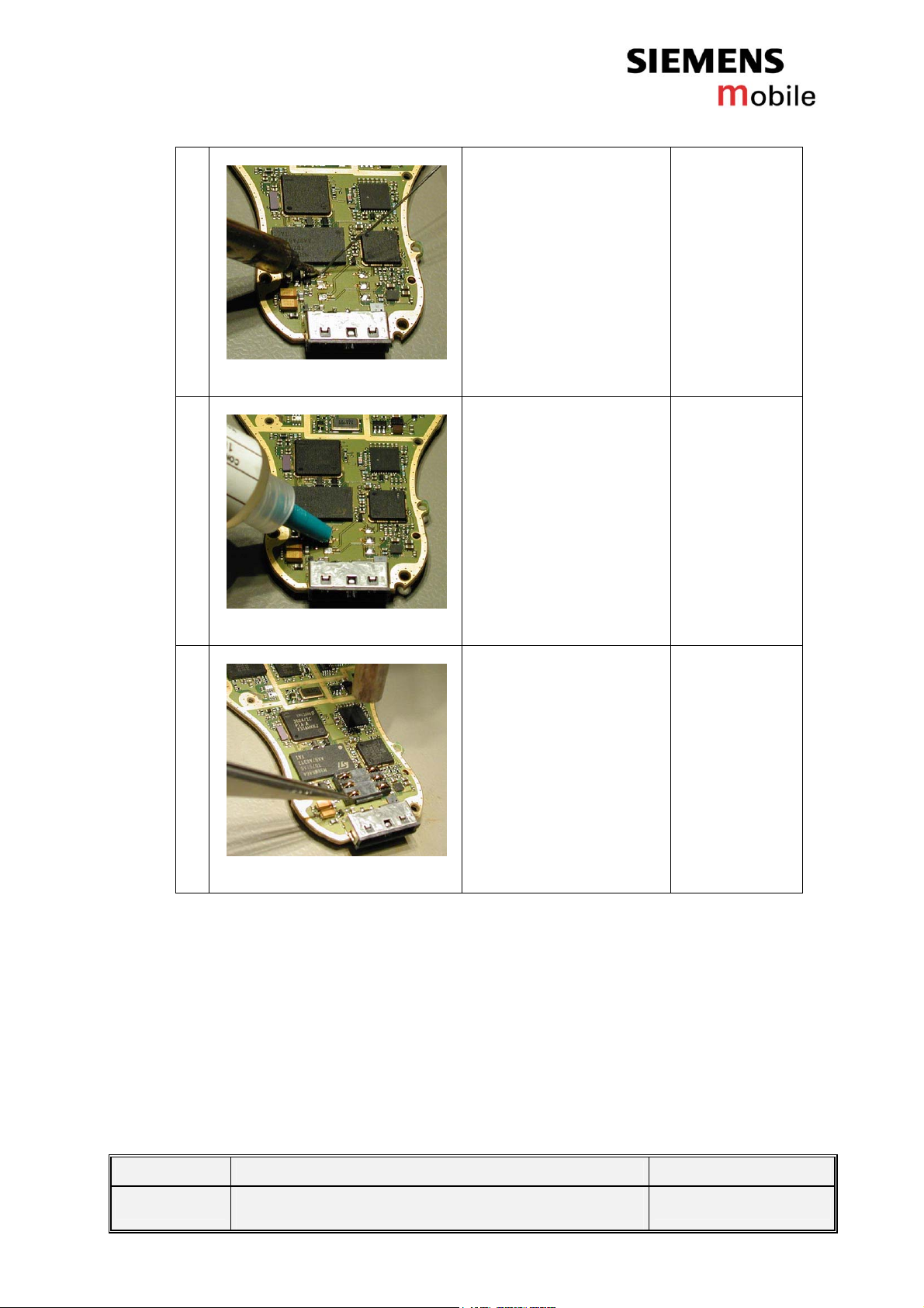
2
Figure 2-2
Add solder on the pads.
3
Figure 2-3
4
Figure 2-4
Add flux on the pads.
Re-solder the new
battery connector by
using a hot air blower.
Check that the
connector is straight and
exactly in right place.
2.3.1.3 Test
Retest the handset after the repair.
V 1.0 Page 5 of 29 ICM MP CCQ GRM
X8
Company Confidential
Copyright 2003© Siemens AG
11/03
Page 6
2.3.2 List of needed material
2.3.2.1 Components
Battery connector
Part Number: L36197-F5059-F181
2.3.2.2 Jigs and Tools
Hot air blower
Tweezers
Inspection lamp
2.3.2.3 Special Tools
None
2.3.2.4 Working materials
Flux
Solder
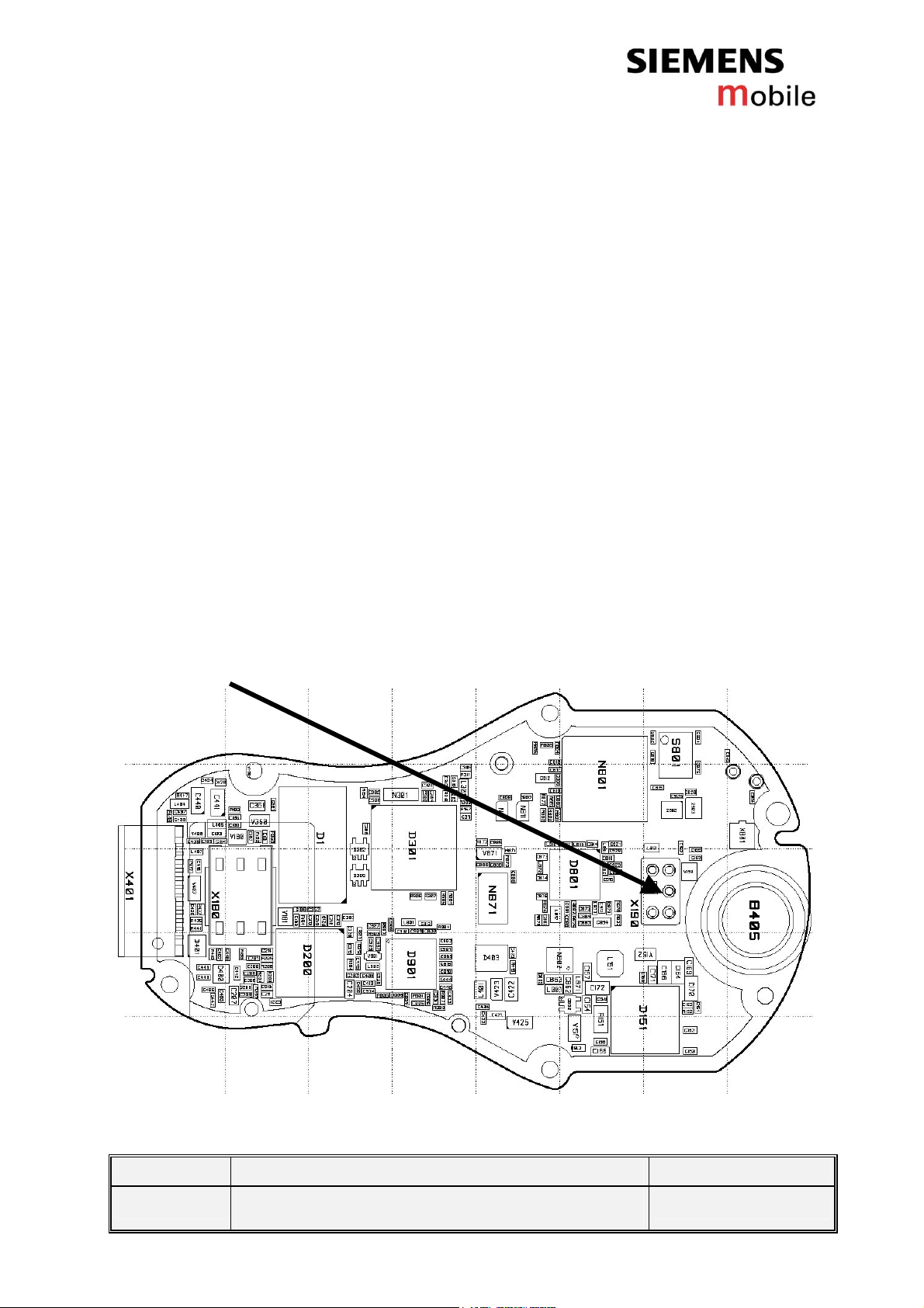
2.3.3 Drawings
Figure 1: Xelibri X8 board, battery connector side
Figure 2: Xelibri X8 battery connector pin description
V 1.0 Page 6 of 29 ICM MP CCQ GRM
X8
Company Confidential
Copyright 2003© Siemens AG
11/03
Page 7
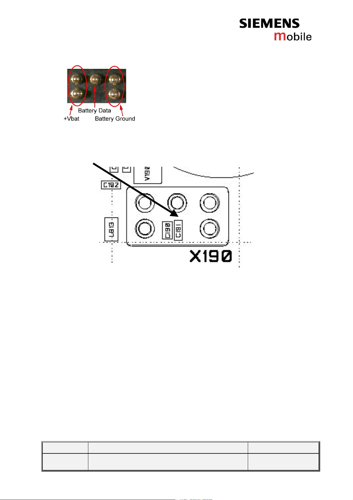
Figure 3: Xelibri X8 battery connector placement (top view)
V 1.0 Page 7 of 29 ICM MP CCQ GRM
X8
Company Confidential
Copyright 2003© Siemens AG
11/03
Page 8
3 SIM CARD READER
3.1 Fault Description
3.1.1 Fault Symptoms for customers:
Text “Insert SIM Card” is on the display even if a
functional SIM card is assembled.
Phone is giving “Card error” message even if a
functional SIM card is assembled.
SIM is not operating.
3.1.2 Fault Symptom on GSM-Tester:
This fault cannot be detected with a GSM-Tester.
3.2 Repair Documentation
3.2.1 Description of procedure:
3.2.1.1 Diagnosis
Check the status of the SIM card reader visually. Watch for oxidation
and dry solder joints.
3.2.1.2 Repair by component change
# Figure Instruction Note
1
Use a hot air blower to
remove the defective
SIM card reader.
Avoid excessive heat!
Watch surrounding
components!!
Figure 3-1
V 1.0 Page 8 of 29 ICM MP CCQ GRM
X8
Company Confidential
Copyright 2003© Siemens AG
11/03
Page 9
2
Figure 3-2
Add solder on the pads.
3
4
Figure 3-3
Figure 3-4
Add flux on the pads.
Re-solder the new SIM
card reader by using a
hot air blower. Check
that the SIM card reader
is straight and exactly in
right place.
3.2.1.3 Test
Retest the handset after the repair.
V 1.0 Page 9 of 29 ICM MP CCQ GRM
X8
Company Confidential
Copyright 2003© Siemens AG
11/03
Page 10

3.2.2 List of needed material
3.2.2.1 Components
SIM reader 6 PINS
Part Number: : L36197-F5116-F753
3.2.2.2 Jigs and Tools
Hot air blower
Tweezers
3.2.2.3 Special Tools
None
3.2.2.4 Working materials
Flux
Solder
3.2.3 Drawings
Figure 1: Xelibri X8 board, SIM card reader side
V 1.0 Page 10 of 29 ICM MP CCQ GRM
X8
Company Confidential
Copyright 2003© Siemens AG
11/03
Page 11

Figure 2: Pin order, top view (SIM connector)
V 1.0 Page 11 of 29 ICM MP CCQ GRM
X8
Company Confidential
Copyright 2003© Siemens AG
11/03
Page 12

4 SYSTEM CONNECTOR
4.1 Fault Description
4.1.1 Fault Symptoms for customers:
Charging problems.
Problems with external loudspeaker or microphone
when using a car kit.
Problems with accessories connected at the system
connector.
Problems with SW booting.
Problems with headset.
Problems with FM Radio.
4.1.2 Fault Symptom on GSM-Tester:
This fault cannot be detected with a GSM-Tester.
4.2 Repair Documentation
4.2.1 Description of procedure:
4.2.1.1 Diagnosis
Check the system connector visually. Watch for dry joints!
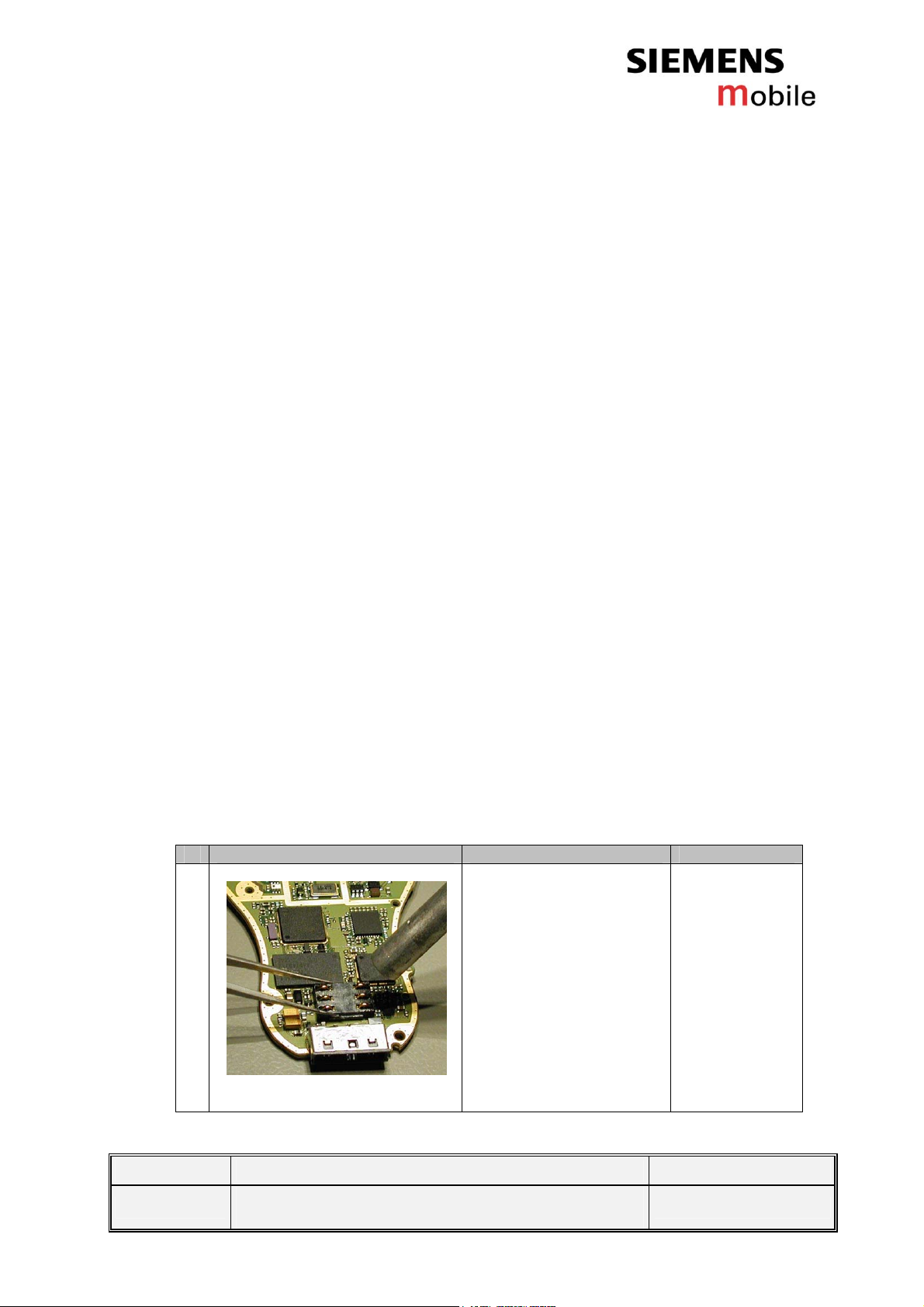
4.2.1.2 Repair by component change
# Figure Instruction Note
1
Use a hot air blower to
remove the defective
system connector.
Avoid excessive heat!
Watch surrounding
components!
Figure 4-1
2
Add solder on the pads.
V 1.0 Page 12 of 29 ICM MP CCQ GRM
X8
Company Confidential
Copyright 2003© Siemens AG
11/03
Page 13

Figure 4-2
3
Figure 4-3
4
Figure 4-4
Add flux on the pads.
Re-solder the new
system connector by
using a hot air blower,
and a soldering iron if
necessary. Check that
the system connector is
straight and exactly in
right place.
4.2.1.3 Test
Charging problems can be discovered by measuring the voltage
between pins 1 (Power) and 2 (GND). Voltage should be between 5V
and 9,5V if system connector is working.
In order to detect an accessory when plugged into the system
connector, the following pins on the connector are used in the
detection scenario: POWER, TX/D+, RX/D-, DATA/CTS, CLK/DCD and
RTS. Table 1 shows the pins and their possible use in a detection
scenario.
V 1.0 Page 13 of 29 ICM MP CCQ GRM
X8
Company Confidential
Copyright 2003© Siemens AG
11/03
Page 14

Table 1: Accessory coding options
Pin No. Signal name Default level Default
direction
1 POWER L(Z) Off Open or charge source (Set by
2 GND GND -
3 TX/D+ H(Z) Out High/Low (Set by Phone)
4 RX/D- L(Z) In Open, Tx or high (Set by accessory)
5 DATA/CTS H(Z) In Open, Tx or low (Set by accessory)
6 RTS H(Z) In Open, Tx or low (Set by accessory)
7 CLK/DCD H(Z) In Open, Tx or low (Set by accessory)
Possible coding options
accessory)
The different coding options for the supported accessories can be seen
in Table 2.
Table 2: Accessory coding table
RX/D- DATA/CTS CLK/DCD RTS Description
OPEN OPEN OPEN OPEN Default: No accessory connected
TX/D+ GND OPEN TX/D+ Headset
TX/D+ GND GND TX/D+ Headset with PTT pressed
HIGH OPEN GND OPEN Car Kit portable
4.2.2 List of needed material
4.2.2.1 Components
System connector Female 12PIN SMD
Part Number: : L36197-F5058-F47
4.2.2.2 Jigs and Tools
Hot air blower
Soldering iron
Tweezers
4.2.2.3 Special Tools
None
V 1.0 Page 14 of 29 ICM MP CCQ GRM
X8
Company Confidential
Copyright 2003© Siemens AG
11/03
Page 15

4.2.2.4 Working materials
Flux
Solder
4.2.3 Drawings
Figure 1: Xelibri X8 board, system connector side
V 1.0 Page 15 of 29 ICM MP CCQ GRM
X8
Company Confidential
Copyright 2003© Siemens AG
11/03
Page 16

Table 3: Xelibri X8 system connector pin description
Pin Name IN/OUT Notes
1 POWER I Charging Current
2 GND Common GND
3 TX O Serial interface, used for Flash
programming and ITP commands
4 RX I Serial interface, used for Flash
programming and ITP commands
5 DATA/CTS I/O Serial interface, used for AT-
commands.
Data line for accessory bus.
Use as CTS in data operation.
Used for accessory detection
6 RTS I Used for accessory detection
7 CLK/DCD I/O Serial interface, used for AT-
commands.
Used for accessory detection
8 Audio L O Dual -ended (other end is Audio R)
output for external receiver (mono)
9 Audio_Ref/V
PP
10 Audio R O Dual -ended (other end is Audio L)
11 Gnd_Micro GND external microphone
12 Micro I Input for external microphone
I Used for 12V flash programming
voltage
output for external receiver (mono)
Table 4: Lumberg signal levels
Pin no. Signal name Level Min [V] Max [V]
3 TX/D+ VOH VOL 2.17 0 3.00 0.20
4 RX/D- VIH VIL 2.10 0 3.60 0.48
5 DATA/CTS VIH VIL
V
OH VOL
6 RTS VIH VIL 2.10 0 3.30 0.46
7 CLK/DCD VIH VIL 2.10 0 3.30 0.46
2.10 0 2.17 0 3.30 0.46 3.00 0.42
V 1.0 Page 16 of 29 ICM MP CCQ GRM
X8
Company Confidential
Copyright 2003© Siemens AG
11/03
Page 17

5 RTC BATTERY
5.1 Fault Description
5.1.1 Fault Symptoms for customers:
The clock is reset when power is switched off.
5.1.2 Fault Symptom on GSM-Tester:
This fault cannot be detected with a GSM-tester.
5.2 Repair Documentation
5.2.1 Description of procedure:
5.2.1.1 Diagnosis
Check the RTC battery visually. Watch for dry joints!
5.2.1.2 Repair by component change
# Figure Instruction Note
1
Figure 5-1
Use a hot air blower to
remove the defective
RTC battery. Avoid
excessive heat!
Watch surrounding
components!
V 1.0 Page 17 of 29 ICM MP CCQ GRM
X8
Company Confidential
Copyright 2003© Siemens AG
11/03
Page 18

2
Figure 5-2
Add solder on the pads.
3
Figure 5-3
4
Figure 5-4
Add flux on the pads.
Re-solder the new RTC
battery by using a hot air
blower and a soldering
iron if necessary. Check
that the RTC battery is
exactly in right place.
Watch surrounding
components!
V 1.0 Page 18 of 29 ICM MP CCQ GRM
X8
Company Confidential
Copyright 2003© Siemens AG
11/03
Page 19

5.2.1.3 Test
Insert a SIM card and fully charged battery into the phone and start it.
Set the correct time. Remove the battery and reinsert it after a minute.
If the time is 00:00, measure backup battery voltage. It should be more
than 2.5V. If the voltage is less, start the phone and wait 15 minutes for
the backup battery to get charged. Repeat the test.
5.2.2 List of needed material
5.2.2.1 Components
Back-up capacitor 0.05F SMD (RTC-battery)
Part Number: L36145-K1310-X297
5.2.2.2 Jigs and Tools
Hot air blower
Soldering iron
Tweezers
5.2.2.3 Special Tools
None
5.2.2.4 Working materials
Flux
Solder
V 1.0 Page 19 of 29 ICM MP CCQ GRM
X8
Company Confidential
Copyright 2003© Siemens AG
11/03
Page 20

5.2.3 Drawings
Figure 1: Xelibri X8 board, RTC battery side
Figure 2: Xelibri X8 RTC battery placement (top view)
V 1.0 Page 20 of 29 ICM MP CCQ GRM
X8
Company Confidential
Copyright 2003© Siemens AG
11/03
Page 21

V 1.0 Page 21 of 29 ICM MP CCQ GRM
X8
Company Confidential
Copyright 2003© Siemens AG
11/03
Page 22

6 LCD CONNECTOR
6.1 Fault Description
6.1.1 Fault Symptoms for customers:
The keymat does not work.
6.1.2 Fault Symptom on GSM-Tester:
This fault cannot be detected with a GSM-tester.
6.2 Repair Documentation
6.2.1 Description of procedure:
6.2.1.1 Diagnosis
Check the RTC battery visually. Watch for dry joints!
6.2.1.2 Repair by component change
# Figure Instruction Note
1
Figure 6-1
Use a hot air blower to
remove the defective
LCD connector. Avoid
excessive heat!
Watch surrounding
components!
V 1.0 Page 22 of 29 ICM MP CCQ GRM
X8
Company Confidential
Copyright 2003© Siemens AG
11/03
Page 23

2
Figure 6-2
Add solder on the pads.
3
Figure 6-3
4
Figure 6-4
Add flux on the pads.
Re-solder the new LCD
connector by using a hot
air blower and a
soldering iron if
necessary. Check that
the LCD connector is
straight and exactly in
right place. Watch
surrounding
components!
6.2.1.3 Test
Addition of visually inspection LCD can be tested through service
menu. Service menu can be activated by pressing *#06# and then
three times “info”. The name of LCD test is “display”.
V 1.0 Page 23 of 29 ICM MP CCQ GRM
X8
Company Confidential
Copyright 2003© Siemens AG
11/03
Page 24

6.2.2 List of needed material
6.2.2.1 Components
PWB Connector 20PIN Female SMD
Part Number: L36197-F5116-F752
6.2.2.2 Jigs and Tools
Hot air blower
Soldering iron
Tweezers
6.2.2.3 Special Tools
None
(LCD connector)
6.2.2.4 Working materials
Flux
Solder
V 1.0 Page 24 of 29 ICM MP CCQ GRM
X8
Company Confidential
Copyright 2003© Siemens AG
11/03
Page 25

6.2.3 Drawings
Figure 1: Xelibri X8 board, LCD connector side
Figure 2: Xelibri X8 LCD connector placement (top view)
V 1.0 Page 25 of 29 ICM MP CCQ GRM
X8
Company Confidential
Copyright 2003© Siemens AG
11/03
Page 26

7 ROCKER KEY LEDS
7.1 Fault Description
7.1.1 Fault Symptoms for customers:
7.1.2 Fault Symptom on GSM-Tester:
7.2 Repair Documentation
Display LEDs are not lit.
This fault cannot be detected with a GSM-tester.
7.2.1 Description of procedure:
7.2.1.1 Diagnosis
Check the display LEDs visually. Watch for dry joints!
7.2.1.2 Repair by component change
# Figure Instruction Note
1
Figure 7-1
Use a hot air blower to
remove the defective
display LED. Avoid
excessive heat!
Watch surrounding
components!
V 1.0 Page 26 of 29 ICM MP CCQ GRM
X8
Company Confidential
Copyright 2003© Siemens AG
11/03
Page 27

2
Figure 7-2
Add solder on the pads.
3
Figure 7-3
4
Figure 7-4
Remove extra solder.
Re-solder the new
display LED by using a
hot air blower and a
soldering iron if
necessary. Watch
surrounding
components!
7.2.1.3 Test
Retest the handset after the repair. Leds can be tested through service
menu. Service menu can be activated by pressing *#06# and then
three times “info”. The name of Led test is “Led/illumination”.
V 1.0 Page 27 of 29 ICM MP CCQ GRM
X8
Company Confidential
Copyright 2003© Siemens AG
11/03
Page 28

7.2.2 List of needed material
7.2.2.1 Components
LED color white 0603 flat top
Part number: L36197-F5116-F751
7.2.2.2 Jigs and Tools
Hot air blower
Soldering iron
Tweezers
7.2.2.3 Special Tools
None
7.2.2.4 Working materials
Flux
Solder
V 1.0 Page 28 of 29 ICM MP CCQ GRM
X8
Company Confidential
Copyright 2003© Siemens AG
11/03
Page 29

7.2.3 Drawings
Figure 1: Xelibri X8 board, display LEDs side
Figure 2: Xelibri X8 display LEDs placement (top view)
V 1.0 Page 29 of 29 ICM MP CCQ GRM
X8
Company Confidential
Copyright 2003© Siemens AG
11/03
 Loading...