

Page 1
Local Service Organization Service Manual
XELIBRI X5
SIEMENS COMMUNICATIONS UNLIMITED
Somebody is waiting for you to call!
Page 2

Table of Contents
1 CELLULAR COMMUNICATION.............................................................................................................2
2 KEY FEATURES .......................................................................................................................................6
3
ACCESSORIES..........................................................................................................................................7
4 EXPLODED VIEW OF X5 .......................................................................................................................8
4.1 Spare Parts List …………………………………………………………………………………….9
5 DISASSEMBLY OF X5.......................................................................................................................... 10
6 ASSEMBLY OF X5.................................................................................................................. 14
7 MOBILE SOFTWARE PROGRAMMING…………………………………………………………….16
8 SIEMENS SERVICE EQUIPMENT USER MANUAL……………………………………………….25
9 INTERNATIONAL MOBILE EQUIPMENT IDENTITY, IMEI.............................................................26
10 GENERAL TESTING INFORMATION...............................................................................................27
ANNEX 1 .................................................................................................................................................... 32
ANNEX 2 .....................................................................................................................................................33
i
Page 3
SIEMENS PTE LTD
XELIBRI X5 LEVEL 2 SERVICE MANUAL
1 Cellular Communication
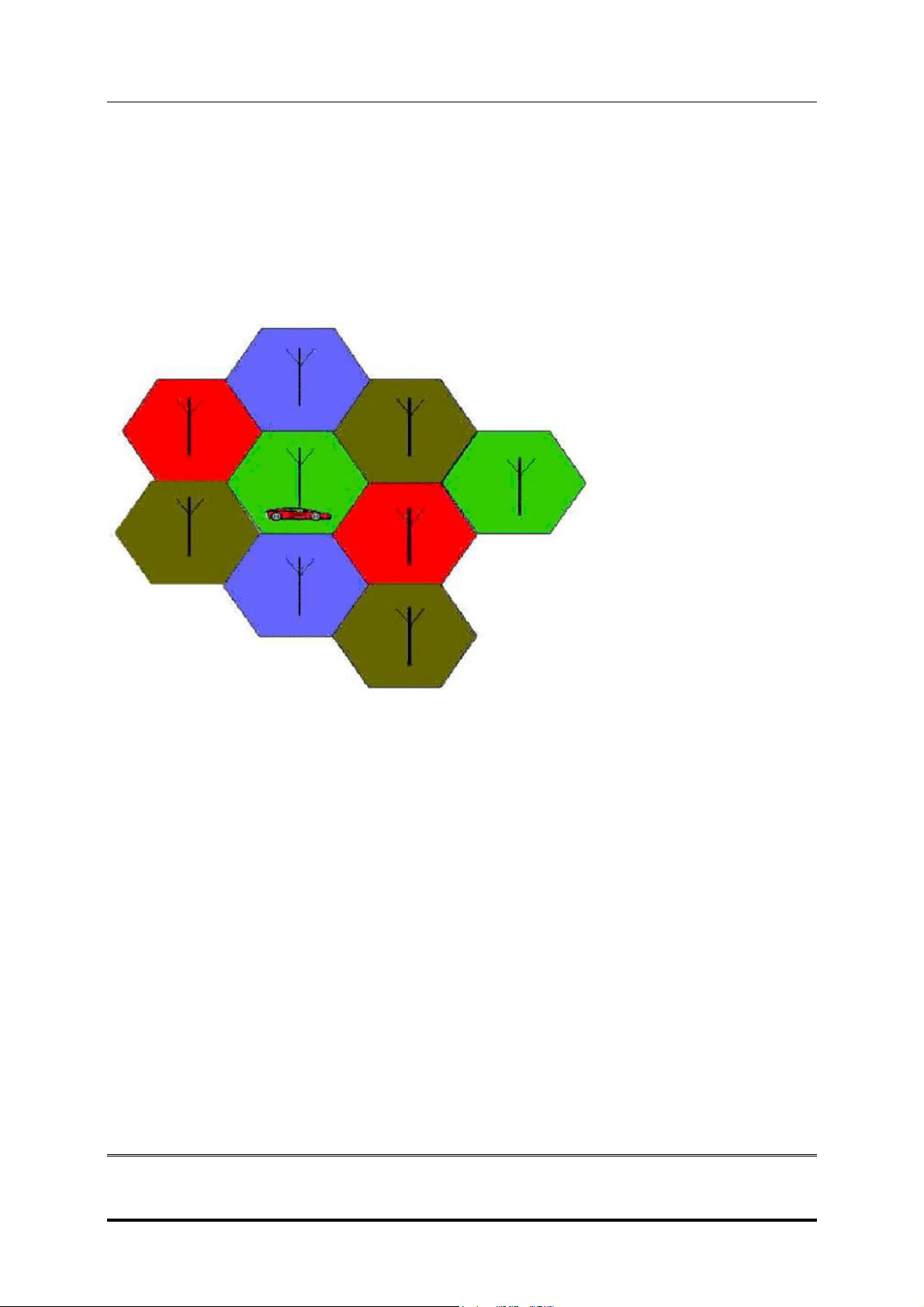
The cellular systems are made up of numerous transmitting and receiving sites, whose
individual coverage areas partially overlap. The concepts of frequency re-use (same
frequency) is used by several sites, allows a high traffic density in a wide area. Due to the
limited transmission range of the terminals, cellular systems are based on a large number of
base stations on the infrastructure side, scattered over the area to cover, with each covering
a fairly small geographical zone called cell. Cells are often represented by hexagons (see
figure 1.1.).
FIGURE 1.1 CELLULAR COVERAGE REPRESENTATION.
GSM Network Architecture.
GSM network can be broadly divided into three broad parts, namely:
1. Mobile Station (MS) carried by the subscriber,
2. Base Station Sub-system (BSS) which controls the radio link with the mobile station.
3. Mobile Switching Centre (MSC) which performs the switching of calls between the mobile
users, and between mobile and fixed network users.
Copyright © Siemens Pte Ltd.
All Rights Reserved
ICM MP CCQ SLI RHQ 2 of 33 Internal Use Only
Page 4
SIEMENS PTE LTD
XELIBRI X5 LEVEL 2 SERVICE MANUAL
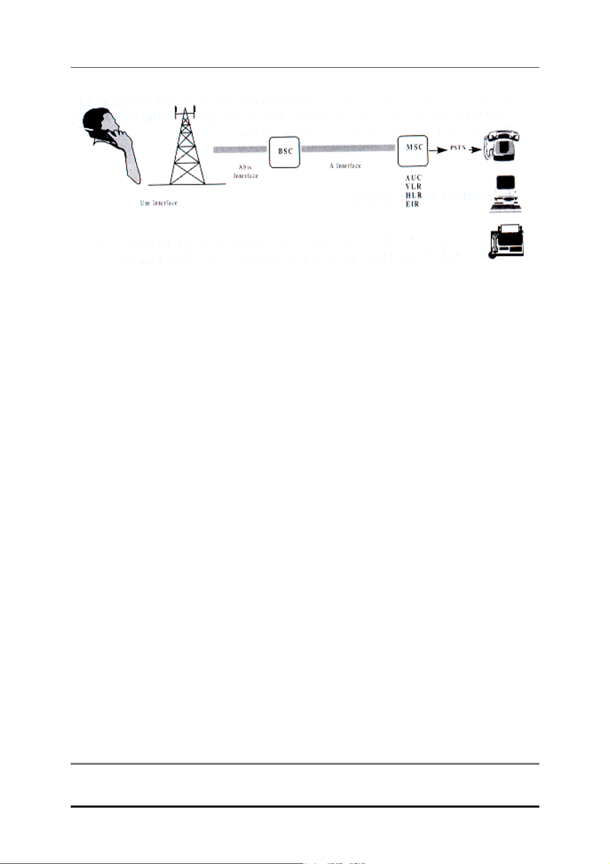
GSM ARCHITECTURE
Each mobile station is given a unique identity. As soon as the mobile phone is turned on, it
registers with the network and is authenticated; as such the network could always find the mobile
phone.
Larger amount of data is being exchanged to and from the following functional blocks in the MSC:
Visitor Location Register, VLR
Stores information about mobile subscribers that enter it coverage area, which is associated with
the geographical area where the mobile is currently roaming. When there is an incoming call for
the mobile, the HLR is interrogated about the present address of the VLR.
Home Location Register, HLR
A database that contains all data concerning the subscription of the mobile subscriber, i.e. their
access capabilities, subscribed services, and supplementary services. It also contains information
about the VLR that is handling the mobile station currently. When the mobile changes location,
the HLR is updated accordingly. It also provides the MSC with information about the MSC area
where the mobile is actually located to allow incoming calls to be routed immediately to the called
party.
Authentication Center, AUC
Stored information that is necessary to protect communication through the air interface against
any intrusions. The legitimacy of the subscriber is established through authentication and
ciphering, which protects the user information against unwanted disclosure.
Equipment Identity Register, EIR
An option the network operator can use to enforce security. With this feature the network can
identify defective or stolen mobile that may not be used in the network.
Copyright © Siemens Pte Ltd.
All Rights Reserved
ICM MP CCQ SLI RHQ 3 of 33 Internal Use Only
Page 5
SIEMENS PTE LTD
XELIBRI X5 LEVEL 2 SERVICE MANUAL
Subscriber Identity Module (SIM)
SIM is a smart card, which has a computer, and memory chip that is permanently installed in the
mobile equipment. It comes in either the size of a credit card or smaller version known as the
plug-in SIM.
The subscriber information, which includes a unique number called the International Mobile
Subscriber Identity (IMSI), is stored in the SIM card. SIM card identifies the subscriber to the
network.
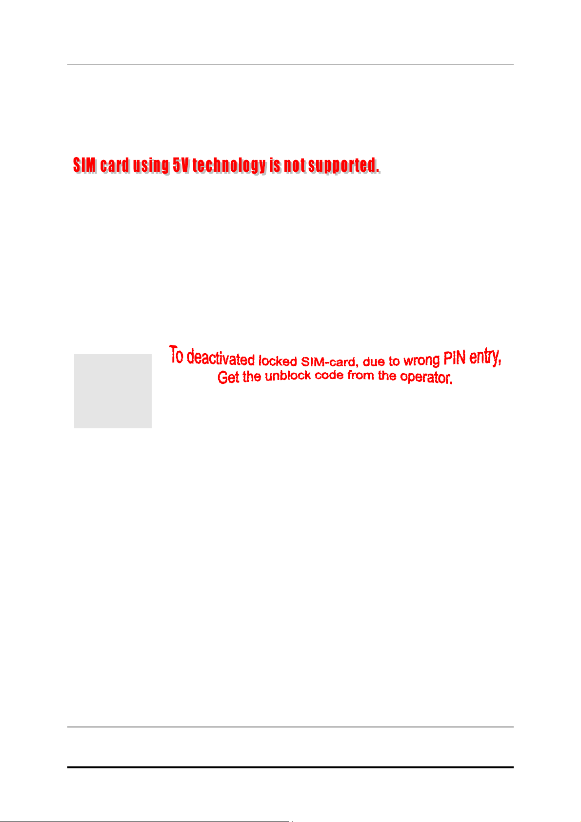
To protect the SIM card from improper use, a security feature, a four digits personal identification
number (PIN), is built in. The PIN is stored in the SIM card and can be changed by the subscriber.
PIN2 is required for additional functions available with a special SIM card (Consult the operator for
more information about the PIN 2).
A code (PUK) is provided for unlocking the SIM card if the SIM card is blocked.
Copyright © Siemens Pte Ltd.
All Rights Reserved
ICM MP CCQ SLI RHQ 4 of 33 Internal Use Only
Page 6

SIEMENS PTE LTD
XELIBRI X5 LEVEL 2 SERVICE MANUAL
SIM Application Toolkit
This is a new GSM feature that has been integrated into the GSM standards in Release 96, with
further enhancements added as part of the Release 97 feature set. This feature came about
because of a desire by Network Operators to offer differentiated services, without the need for the
Mobile Manufacturers having to build different variant for different customers. The unique service
offered by the Operator is placed as an application on the SIM and that could work on any mobile
that supports the Toolkit feature.
There is a distinct set of commands between the mobile and the SIM specifically for the Toolkit
that allows the SIM application and the mobile to communicate independently of the GSM
communication between the SIM and the mobile. Henceforth, the SIM Application Toolkit and
GSM functionality on the SIM are separated logically. The Toolkit can interact directly with the
mobile itself and adding itself to the mobile menu.
“Proactive SIM” is a mechanism whereby the SIM can initiate actions to be taken by the mobile.
These actions include:
• Send short message
• Set up a voice call to a number held by the SIM
• Send a Supplementary Service (SS) control or Unstructured Supplementary Services
Data (USSD) string
• Play a tone in the mobile’s ear piece or ringer
• Initiate a dialogue with the user
• Provide local information from the mobile to the SIM
• Data download to the SIM from network
SIM Applications Toolkit (SAT) allows the flexibility to update the SIM, to change the services and
download new services over the air. In the SAT specification, the short message service is a key
mechanism for personalizing the SIM in each user’s GSM phone. It is designed as a client-server
application. The X6 supports the SAT specification.
Extended GSM 900, E-GSM
This is a new standard that allows Network Operators to increase their capacity through an
extended frequency. The frequency range of E-GSM is as follows:
• Mobile Transmit: 880,2 - 914,8 MHz
• Mobile Receive: 925,2 - 959,8 MHz
Xelibri X5 is a GSM Phase 2 / Phase 2+ Dualband E-GSM 900 / GSM 1800 mobile phone.
The following is the link to the support information regarding the mobile phone.
http://www.xelibri.com
Copyright © Siemens Pte Ltd.
All Rights Reserved
ICM MP CCQ SLI RHQ 5 of 33 Internal Use Only
Page 7

SIEMENS PTE LTD
XELIBRI X5 LEVEL 2 SERVICE MANUAL
2 Key Features
ITEM Specification
Frequency Band: E-GSM 900 / GSM 1800
Screen: 108 X 80 Pixels FSTN;4096 colour
Battery: 680 mAh Li-ION
Weight 73.5g
Talk time 340 minutes.
Standby time 350 hours(standard battery)
Colour Mercury ,Ultra Blue
Antenna Integrated
Ringtones 23 item music with 16 chord
Game 2 kinds
EMS/MMS Support
Language English, German, France, Spanish, Portuguese, Italian,
Dutch, Chinese traditional / simplified
Power Classes
Receiving sensitivity for all
channels without fading:
SIM card 1.8/3.0V
Temperature ranges Normal operation: -10 ~ +55 centigrade
SAR (Absorption Rate) 0.76 W/kg
E-GSM 900: Class 4 (2W)
E-GSM 1800: Class 1 (1W)
E-GSM900: <-106 dBm
GSM1800: < - 105 dBm
Copyright © Siemens Pte Ltd.
All Rights Reserved
ICM MP CCQ SLI RHQ 6 of 33 Internal Use Only
Page 8

SIEMENS PTE LTD
XELIBRI X5 LEVEL 2 SERVICE MANUAL
3 Accessories
Basic Li-ION Battery (680mah)
Travel Charger (100~240V) )
Basic Car Pack Allows hands-free talking and
simultaneously charges your Xelibri in
the car.
Features a car charger and headset
with special connector.
Car Charger Charger for the cigarette lighter socket
in your car
Car Kit Portable Handsfree kit with integrated
loudspeaker and microphone and autoanswer feature. Also charges your
Xelibri
Headset PTT Enable convenient and safe hands-free
use. It concludes a button in the
microphone for handling calls.
Copyright © Siemens Pte Ltd.
All Rights Reserved
ICM MP CCQ SLI RHQ 7 of 33 Internal Use Only
Page 9
SIEMENS PTE LTD
XELIBRI X5 LEVEL 2 SERVICE MANUAL
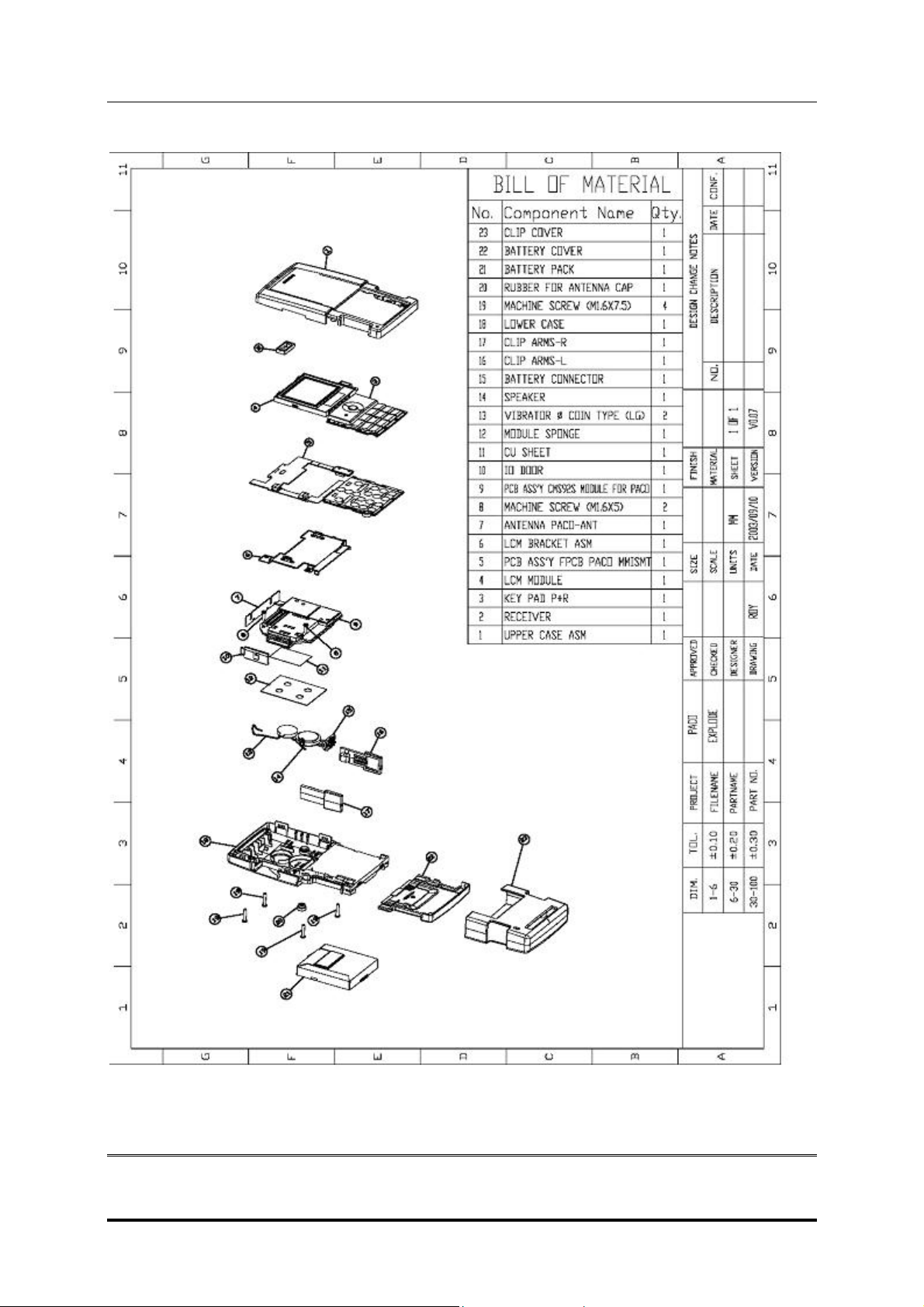
4 Exploded View of X5
Copyright © Siemens Pte Ltd.
All Rights Reserved
ICM MP CCQ SLI RHQ 8 of 33 Internal Use Only
Page 10
SIEMENS PTE LTD
XELIBRI X5 LEVEL 2 SERVICE MANUAL
4.1 Spare Parts List
Ref-Nr Part Description L-Number Level
1 Upper case black L36197-F5144-F744 1
1 Upper case white L36197-F5144-F745 1
2 Receiver L36197-F5144-F762 1
3 Keypad EMEA black L36197-F5144-F763 1
3 Keypad EMEA white L36197-F5144-F764 1
3 Keypad China black L36197-F5144-F766 1
3 Keypad China white L36197-F5144-F767 1
4 LCD Module L36197-F5144-F769 1
5 MMI Board incl Micro L36197-F5144-F770 1
6 Bracket L36197-F5144-F771 1
7 Antenna L36197-F5144-F782 1
8 Screw 1,6x5 L36197-F5144-F783 1
9 Swapboard L36880-Q9250-A10 2
10 I O Door black L36197-F5144-F785 0
10 I O Door White L36197-F5144-F786 0
11 CU Sheet Max L36197-F5144-F788 1
12 Module Sponge L36197-F5144-F791 1
13 Vibra L36197-F5144-F806 1
14 Speaker L36197-F5144-F807 1
15 Battery connector L36197-F5144-F835 1
16 Clip arm L black L36197-F5144-F837 1
16 Clip arm L white L36197-F5144-F855 1
17 Clip arm R black L36197-F5144-F858 1
17 Clip arm R white L36197-F5144-F869 1
18 Lower case black L36197-F5145-F2 1
18 Lower case white L36197-F5145-F228 1
19 Screw 1,6x7,5 L36197-F5145-F230 1
20 Rubber for Ant black L36197-F5145-F231 0
20 Rubber for Ant white L36197-F5145-F262 0
21 Battery pack L36145-K1310-X287 0
22 Battery cover black L36197-F5145-F263 0
22 Battery cover white L36197-F5145-F282 0
23 Clip cover black L36197-F5145-F285 0
23 Clip cover white L36197-F5145-F286 0
Acc Lanyard black short and long L36197-F5100-F576 0
Acc Lanyard blue short and long L36197-F5120-F699 0
Water contact indicator L36197-F5118-F284 1
Copyright © Siemens Pte Ltd.
All Rights Reserved
ICM MP CCQ SLI RHQ 9 of 33 Internal Use Only
Page 11
SIEMENS PTE LTD
XELIBRI X5 LEVEL 2 SERVICE MANUAL
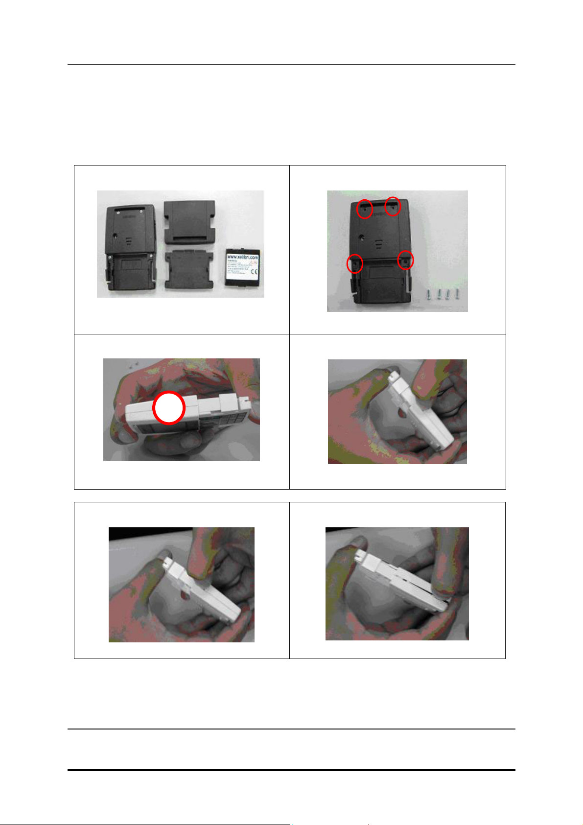
5 Disassembly of X5
Note: It is a requirement for the service personnel to observe ESD protection rules while servicing the X5.
Instruction
Keep all contact surfaces and the display clean of skin oil. Use gloves or finger clove!
Step 1
Remove the battery connector, clip cover and
battery.
Step 3
Open the case: to pry open the case. There is a
catch in the case as shown in the circle
.
Step 2
Remove the 4 screws (size 1,6 * 7,5mm) on the
back cover.
Step 4a
Use the fingernail to press open the catch
Step 4b
Step 4c
The sides
Copyright © Siemens Pte Ltd.
All Rights Reserved
ICM MP CCQ SLI RHQ 10 of 33 Internal Use Only
The sides
Page 12

SIEMENS PTE LTD
XELIBRI X5 LEVEL 2 SERVICE MANUAL
Step 4d
The top.
Step 5b
Step 5a
Take out the keypad from the front cover. (The
spare part: front cover, contains a lens and
sponge; Never remove the lens from the front
cover.) Speaker on the front cover. (Do not
remove speaker if not damaged)
Step 6
The phone with front cover and keypad removed
Step 7a
Open the LCM positioning tab (see the red circle)
Push the LCM bracket positioning tab slowly and
carefully. Use some strength upward
Use a tweezers to release the LCM connector
(see the red circle) carefully.
Step 7b
Display module removed.
Copyright © Siemens Pte Ltd.
All Rights Reserved
ICM MP CCQ SLI RHQ 11 of 33 Internal Use Only
Page 13

SIEMENS PTE LTD
XELIBRI X5 LEVEL 2 SERVICE MANUAL
Step 8
Pull the buzzer line out from the MMI board
Step 10
Step 9
Pull the vibrator line out from the MMI board
Step 11
Remove the MMI Board
Step 12
Remove the 2 screws short 1,6 * 5 mm 16 cNm
on the bracket.
There is a fixing position in the MMI connector.
Check the Connector is good. Use a pair of
tweezers to pry off the fixing position.
Step 13a
Remove the PCBA Module from the back cover.
Copyright © Siemens Pte Ltd.
All Rights Reserved
ICM MP CCQ SLI RHQ 12 of 33 Internal Use Only
Page 14

SIEMENS PTE LTD
XELIBRI X5 LEVEL 2 SERVICE MANUAL
Step 13b
Step 14b
Step 14a
a)
b)
Remove the RF antenna from the PCBA module.
a) RF antenna; b) Module
Step 15
Turn over the Module (The red arrows show the
direction of the movements)
Remove the sponge and the RF Antenna.
Copyright © Siemens Pte Ltd.
All Rights Reserved
ICM MP CCQ SLI RHQ 13 of 33 Internal Use Only
Page 15

SIEMENS PTE LTD
XELIBRI X5 LEVEL 2 SERVICE MANUAL
6 Assembly of X5
Step 1
Assemble the Module with Antenna.
Step 3
Stick the Sponge.
Note: The sponge is designed to enhance the
adhesive force to make antenna connection.
Step 2
Stick the foil on the Module.
Note: In order to fix the antenna, apply adhesive
force on the Module. If it is not done properly, the
antenna may not work properly because of the bad
connection with Module.
Step 4
Assemble the I-O Door on the Back cover.
Step 5
a)
b)
c)
Assemble the a) Vibrator, b) Buzzer and c) Battery
Connector on the Back cover.
Step 6
Place the Module into the Back cover and secure it
to the casing. Note:
Make sure that the antenna
is turned and mounted correctly.
Copyright © Siemens Pte Ltd.
All Rights Reserved
ICM MP CCQ SLI RHQ 14 of 33 Internal Use Only
Page 16

SIEMENS PTE LTD
XELIBRI X5 LEVEL 2 SERVICE MANUAL
Step 7
Put the metal plate on the module and back cover.
Secure two 1.6 * 5 mm screws located as shown in
the red circles. Set the torque to 16 cNm.
Step 9
R1
Step 8
a)
b)
c)
d)
Place the MMI Board on the metal plate, and
connect the a) vibrator and b) buzzer lines to the
MMI board connector. c) Connect the MMI board to
the Module and d) Mount the display and connect it
to the connector.
Step 10
L1
Mount the clips R1 and L1 as shown.
Assemble the Front and Back covers.
Step 11
Secure the four 1.6 * 7.5 mm screws as shown in the bold circles. Set the torque to 16cNm. Place the cap
as shown in the dotted circle.
Copyright © Siemens Pte Ltd.
All Rights Reserved
ICM MP CCQ SLI RHQ 15 of 33 Internal Use Only
Page 17

SIEMENS PTE LTD
XELIBRI X5 LEVEL 2 SERVICE MANUAL
7 Mobile Software Programming
EQUIPMENT
Before the installation of the Download/configuration program check your equipment :
- Standard desktop PC. Pentium III / 128 Mo (with standard serial com)
- Windows NT environment
For the connection between PC and mobile use:
- Serial adapter (BootAdapter 2002 – see photo) L36880-N9241-A200.
- Connect the BootAdapter to power
- Connect the PC and BootAdapter with standard serial cable
- Use specific cable to connect mobile and BootAdapter F30032-P226-A1
PROGRAM INSTALLATION
To install the soft, execute: setup_dwlpc.exe and follow instructions…
To launch the program: C:\Download_Siemens\dwlDev.exe
Following window appears:
Copyright © Siemens Pte Ltd.
All Rights Reserved
ICM MP CCQ SLI RHQ 16 of 33 Internal Use Only
Page 18

SIEMENS PTE LTD
XELIBRI X5 LEVEL 2 SERVICE MANUAL
PROGRAM USE
a/ In Download type, choose :Software ( it’s the default value )
b/ In Select a Project choose :
5087-5_RAM 16bits (CMS92-S) (it’s not the default value)
The other choice is 5087_RAM 16bits (S128)
c/ Then click on Select a file :
To update product with new software, you need to know what is exactly its configuration.
For example:
- Twiggy with EMEA configuration or
- Emma with APAC configuration etc …
With this information you can select the file.cla you want to download
X6 - Twiggy
- EMEA = Vxxxx_twiggy_emea.cla
- APAC = Vxxxx_twiggy_apac.cla
X7 - Emma
- EMEA = Vxxxx_emma_emea.cla
- APAC = Vxxxx_emma_apac.cla
X5 - Paco
- EMEA = Vxxxx_paco_emea.cla
- APAC = Vxxxx_paco_apac.cla
Select the good file and click on OK (wait few minutes during loading)
d/ Select the Serial Port where your « Bootadapter 2002 » is plugged
Copyright © Siemens Pte Ltd.
All Rights Reserved
ICM MP CCQ SLI RHQ 17 of 33 Internal Use Only
Page 19

SIEMENS PTE LTD
XELIBRI X5 LEVEL 2 SERVICE MANUAL
e/ Put a battery in your mobile and plug in mobile with serial connector.
f/ Press Start
Message TURN THE MOBILE ON appears, then press the OnKey of the mobile.
Wait the end of the download (4 – 10 minutes) then click OK.
Copyright © Siemens Pte Ltd.
All Rights Reserved
ICM MP CCQ SLI RHQ 18 of 33 Internal Use Only
Page 20

SIEMENS PTE LTD
XELIBRI X5 LEVEL 2 SERVICE MANUAL
Configuration
The program « Service_Tool » allows to do a complete configuration of mobile without Imei
modification. This application permits to re-use mobile by deleting previous parameter and writing
new parameters in product. This program is simple, operator plugs in product to serial connector,
select a part number and launch the personalization.
Program Installation
To install “Service_Tool” program on your PC use the install kit delivery
Install Kit contents: setup.exe / service_.001 / service_.002
Installation:
Run the Setup.exe file supply with the install kit.
Default installation path is "C:\service_tool_S138_vx\" (“vx” is the release version)
- Unzip and copy Setting Files data on the same directory
After installation you should have in the install directory the following things: (see image)
Setting files data
delivered with
Service_tool
Copyright © Siemens Pte Ltd.
All Rights Reserved
ICM MP CCQ SLI RHQ 19 of 33 Internal Use Only
Depend of the
software version
Page 21

SIEMENS PTE LTD
XELIBRI X5 LEVEL 2 SERVICE MANUAL
Program Use
Because of software compatibility, a new “service_tool” program version is necessary for
each new product software!
a/ Run the file « Service_Tool.exe », the program displays window on screen.
The program updates automatically the part number list you can use for the configuration.
In the bottom of the window you can see the program version and product software
compatibility.
Siemens part
number delivered
with the zip file
(Setting Files)
Project name
Software
b/ Select the serial com number where BootAdapter is connected.
Copyright © Siemens Pte Ltd.
All Rights Reserved
ICM MP CCQ SLI RHQ 20 of 33 Internal Use Only
Page 22

SIEMENS PTE LTD
XELIBRI X5 LEVEL 2 SERVICE MANUAL
c/ Select the Siemens part number corresponding to your product configuration.
(Part number value depends of the project)
The program ask you to confirm the selection
After the validation, “Selected Variant” box, displays the part number selected.
The program is on the waiting mode (you can plug a product)
Copyright © Siemens Pte Ltd.
All Rights Reserved
ICM MP CCQ SLI RHQ 21 of 33 Internal Use Only
Page 23

SIEMENS PTE LTD
XELIBRI X5 LEVEL 2 SERVICE MANUAL
d/ Put a battery in your mobile and plug in mobile with serial connector.
e/ Start the test by pressing the “START TEST” button.
A window “Turn the mobile On” appears: The switch on mobile.
(With the BootAdapter 2002 the mobile start automatically).
In case of start problem a new window is displaying.
Press OK, remove the battery and serial connector and do the test again. If you meet the same
problem
- check the battery charge
- check the mobile connector
If it is no problem, the Configuration test runs.
Copyright © Siemens Pte Ltd.
All Rights Reserved
ICM MP CCQ SLI RHQ 22 of 33 Internal Use Only
Page 24

SIEMENS PTE LTD
XELIBRI X5 LEVEL 2 SERVICE MANUAL
When test is finished, a message is displayed.
f/ Test is OK, remove the battery and unplug the serial connector.
After some seconds the program come back to the waiting mode.
Copyright © Siemens Pte Ltd.
All Rights Reserved
ICM MP CCQ SLI RHQ 23 of 33 Internal Use Only
Page 25

SIEMENS PTE LTD
XELIBRI X5 LEVEL 2 SERVICE MANUAL
Troubleshooting
During customization you could meet some error
The following error message appears when pack data on the product is not in
accordance with parameters specified by the part number selected.
Solution: download the good file.cla or change the selected variant.
The following error message appears when:
- Software version on product is wrong
- PN compatibility is wrong (PN number is not allowed with this software version)
Copyright © Siemens Pte Ltd.
All Rights Reserved
ICM MP CCQ SLI RHQ 24 of 33 Internal Use Only
Page 26

SIEMENS PTE LTD
XELIBRI X5 LEVEL 2 SERVICE MANUAL
8 Siemens Service Equipment User Manual
Introduction
Every LSO repairing Siemens handset must ensure that the quality standards are observed.
Siemens has developed an automatic testing system that will perform all necessary
measurements. This testing system is known as:
Siemens Mobile Service Equipment
Using this system vastly simplifies the repair of the phones and will make sure that:
1. All possible faults are detected
2. Sets, which pass the test, will be good enough to return to customer.
Starting from the P35 Series, Siemens will introduce a simpler and faster testing platform for
testing a repaired Siemens mobile phone. The testing platforms are either base on R&S CMD
53/55 or CTS55 GSM test set or CMD200 with a software called (CTS, CMD, or CMU-GO).
There is also test software available for testing with the Willtek 4201S the 4107 and the 4400
GSM test set called (CATS 4200 or CATS4400).
THE LSO WILL HAVE TO PURCHASE THE SYSTEM, CHOOSING BETWEEN
THE COMPLETE PACKAGE OR SUB-SET OF IT.
A FULLY AUTOMATIC TEST PROCEDURE IS ONLY
POSSIBLE IF THE COMPLETE SYSTEM IS INSTALLED.
Make sure that your CTS firmware is Version 3.01 or higher. For CMD 55 it
must be Version 4.03 and higher. Please check with the Service Info
SB_0500 for the CTS/CMD Hardware Options.
Copyright © Siemens Pte Ltd.
All Rights Reserved
ICM MP CCQ SLI RHQ 25 of 33 Internal Use Only
Page 27

SIEMENS PTE LTD
XELIBRI X5 LEVEL 2 SERVICE MANUAL
9 International Mobile Equipment Identity, IMEI
IMEI Access: *#06#
Copyright © Siemens Pte Ltd.
All Rights Reserved
ICM MP CCQ SLI RHQ 26 of 33 Internal Use Only
Page 28

SIEMENS PTE LTD
XELIBRI X5 LEVEL 2 SERVICE MANUAL
10 General Testing Information
General Information
The technical instruction for testing GSM mobile phones is to ensure the best repair quality.
Validity
This procedure is to apply for all from Siemens AG authorized level 2 up to 2.5e workshops.
Procedure
All following checks and measurements have to be carried out in an ESD protected
environment and with ESD protected equipment/tools. For all activities the international ESD
regulations have to be considered.
Get delivery:
Ensure that every required information like fault description, customer data a.s.o. is
available.
Ensure that the packing of the defective items is according to packing requirements.
Ensure that there is a description available, how to unpack the defective items and
what to do with them.
Enter data into your database:
(Depends on your application system)
Ensure that every data, which is required for the IRIS-Reporting is available in your
database.
Ensure that there is a description available for the employees how to enter the data.
Incoming check and check after assembling:
!! Verify the customers fault description!!
After a successful verification pass the defective item to the responsible
troubleshooting group.
If the fault description can not be verified, perform additional tests to save time and to
improve repair quality.
- Switch on the device and enter PIN code if necessary unblock phone.
- Check the function
- Check the display for error in line and row
- Check the ringer/loudspeaker acoustics by individual validation.
- Perform a GSM Test as described on page 29.
Check the storage capability:
Copyright © Siemens Pte Ltd.
All Rights Reserved
ICM MP CCQ SLI RHQ 27 of 33 Internal Use Only
of all keys including side keys.
, and for illumination.
Page 29

SIEMENS PTE LTD
XELIBRI X5 LEVEL 2 SERVICE MANUAL
Check internal resistance and capacity of the battery.
Check battery charging capability of the mobile phone.
Check charging capability of the power supply.
Check current consumption of the mobile phone in different mode.
Visual inspection:
Check the entire board for liquid damages.
Check the entire board for electrical damages.
Check the housing of the mobile phone for damages.
SW update:
Carry out a software update and data reset according to the master tables and
operator/customer requirements.
Repairs:
The disassembling as well as the assembling of a mobile phone has to be carried
out by considering the rules mentioned in the dedicated manuals. If special
equipment is required the service partner has to use it and to ensure the correct
function of the tools.
If components and especially soldered components have to be replaced all rules
mentioned in dedicated manuals or additional information e.g. service information
have to be considered
Copyright © Siemens Pte Ltd.
All Rights Reserved
ICM MP CCQ SLI RHQ 28 of 33 Internal Use Only
Page 30

SIEMENS PTE LTD
XELIBRI X5 LEVEL 2 SERVICE MANUAL
GSM Test:
Connect the mobile/board via internal antenna (antenna coupler) and external
antenna (car cradle) to a GSM tester.
Use a Test SIM.
Skip GSM 900/GSM1800 or GSM1900 test cases if not performed by the mobile
phone.
Copyright © Siemens Pte Ltd.
All Rights Reserved
ICM MP CCQ SLI RHQ 29 of 33 Internal Use Only
Page 31

SIEMENS PTE LTD
XELIBRI X5 LEVEL 2 SERVICE MANUAL
Copyright © Siemens Pte Ltd.
All Rights Reserved
ICM MP CCQ SLI RHQ 30 of 33 Internal Use Only
Page 32

SIEMENS PTE LTD
XELIBRI X5 LEVEL 2 SERVICE MANUAL
Final Inspection:
The final inspection contains:
1) A 100% network test (location update, and set up call).
2) A random sample checks of:
- data reset (if required)
- optical appearance
- complete function
3) Check if PIN-Code is activated (delete the PIN-Code if necessary).
Basis is the international standard of DIN ISO 2859.
Use Normal Sample Plan Level II and the Quality Border 0,4 for LSO.
Remark: All sample checks must be documented.
Copyright © Siemens Pte Ltd.
All Rights Reserved
ICM MP CCQ SLI RHQ 31 of 33 Internal Use Only
Page 33

SIEMENS PTE LTD
XELIBRI X5 LEVEL 2 SERVICE MANUAL
Annex 1
Test SIM Card
There are 2 different “Test-SIM-Cards” in use
a) Test SIM from the company “ORGA”
Pin 1 No: 0000
PUK 1: 12345678
Pin 2 No: 0000
PUK 2: 23456789
b) Test SIM from the company “T-D1”
Pin 1 No: 1234
PUK 1: 76543210
Pin 2 No: 5678
PUK 2: 98765432
Copyright © Siemens Pte Ltd.
All Rights Reserved
ICM MP CCQ SLI RHQ 32 of 33 Internal Use Only
Page 34

SIEMENS PTE LTD
XELIBRI X5 LEVEL 2 SERVICE MANUAL
Annex 2
Battery – Date – Code overview
Varta
Date code example N 9 A VA
Year (N:2001, O:2002...) Supplier Code
Month (1:Jan, 2:Feb,…9:Sep, O:Oct, N:Nov, D:Dec) (Maker’s marking)
Revision Letter (A, B,…)
Hitachi / Maxwell
Date code example N 9 A MX
Year (N:2001, O:2002...) Supplier Code
Month (1:Jan, 2:Feb,…9:Sep, O:Oct, N:Nov, D:Dec) (Maker’s marking)
Revision Letter (A, B,…)
Sanyo
Date code example N 9 A SY
Year (N:2001, O:2002...) Supplier Code
Month (1:Jan, 2:Feb,…9:Sep, O:Oct, N:Nov, D:Dec) (Maker’s marking)
Revision Letter (A, B,…)
NEC
Date code example N 8 A NT
Year (N:2001, O:2002...) Supplier Code
Month (1:Jan, 2:Feb,…9:Sep, O:Oct, N:Nov, D:Dec) (Maker’s marking)
Revision Letter (A, B,…)
Panasonic
Date code example O N A PAN
Year (N:2001, O:2002...) Supplier Code
Month (1:Jan, 2:Feb,…9:Sep, O:Oct, N:Nov, D:Dec) (Maker’s marking)
Revision Letter (A, B,…)
Sony
Date code example P N A SO
Year (O:2002, P:2003...) Supplier Code
Month (1:Jan, 2:Feb,…9:Sep, O:Oct, N:Nov, D:Dec) (Maker’s marking)
Revision Letter (A, B,…)
Copyright © Siemens Pte Ltd.
All Rights Reserved
ICM MP CCQ SLI RHQ 33 of 33 Internal Use Only
 Loading...