

Page 1

Information and Communication Mobile
Level 2.5
Repair
Documentation for XELIBRI
X2 & X4
Issue Date Author Description
0.9 15.04.03 Noblet First release
1.0 22.05.03 Lerner Layout update and 1st official release
V 1.0 Page 1 of 14 ICM MP CCQ
GRM
X2 / X4 Company Confidential
Copyright 2003© Siemens AG
04/03
Page 2

Information and Communication Mobile
Mobile Phones
Table of Contents:
1 XELIBRI Level2.5 Repair Location Code........................................................................................ 4
2 BATTERY CONNECTOR................................................................................................................. 5
2.1 Affected Units................................................................................................................................................ 5
2.1.1 Type: Xelibri ................................................................................................................................................... 5
2.1.2. Affected IMEIs/Date Codes: All/All................................................................................................................... 5
2.1.3. Affected SW-versions: All .................................................................................................................................. 5
2.1.4 Fault Code for LSO reporting: NA........................................................................................................................ 5
2.2 Fault Description ..........................................................................................................................................5
2.2.1 Fault Symptoms for customers:................................................................................................................................ 5
2.2.2 Fault Symptom on GSM tester:................................................................................................................................ 5
2.2.3 Component Information........................................................................................................................................... 5
2.3. Priority: ........................................................................................................................................................6
2.4. Repair document..........................................................................................................................................6
2.4.1 Description of procedure.......................................................................................................................................... 6
2.4.1.1. Diagnosis.......................................................................................................................................................... 6
2.4.1.2. Repair by component change ........................................................................................................................... 6
2.4.1.3 Repair by SW-booting....................................................................................................................................... 6
2.4.1.4 Test.................................................................................................................................................................... 6
2.4.2 List of material......................................................................................................................................................... 6
2.4.2.1 Components....................................................................................................................................................... 6
2.4.2.2 Jigs and Tools.................................................................................................................................................... 6
2.4.2.3 Special tools ...................................................................................................................................................... 7
2.4.2.4 Working materials............................................................................................................................................. 7
2.4.3 Drawing.................................................................................................................................................................... 7
3 I/O CONNECTOR ............................................................................................................................. 8
3.1 Affected Units...........................................................................................................................................8
3.1.1 Type: Xelibri ................................................................................................................................................. 8
3.1.2 Affected IMEIs/Date Codes: All/All................................................................................................................. 8
3.1.3 Affected SW-versions: All............................................................................................................................... 8
3.1.4 Fault Code for LSO reporting: NA.................................................................................................................... 8
3.2 Fault Description......................................................................................................................................8
3.2.1 Fault Symptoms for customers:......................................................................................................................... 8
3.2.2 Fault Symptom on GSM tester:......................................................................................................................... 8
3.2.3 Component Information .................................................................................................................................... 8
3.3 Priority:.....................................................................................................................................................9
3.4 Repair document...................................................................................................................................... 9
3.4.1 Description of procedure................................................................................................................................... 9
3.4.1.1 Diagnosis....................................................................................................................................................... 9
3.4.1.2 Repair by component change ........................................................................................................................ 9
3.4.1.3 Repair by SW-booting................................................................................................................................... 9
3.4.1.4 Test................................................................................................................................................................ 9
3.4.2 List of material .................................................................................................................................................. 9
3.4.2.1 Components................................................................................................................................................... 9
3.4.3 Jigs and Tools.................................................................................................................................................. 10
3.4.4 Special tools .................................................................................................................................................... 10
3.4.5 Working materials........................................................................................................................................... 10
3.4.6 Drawing........................................................................................................................................................... 10
V 1.0 Page 2 of 14 ICM MP CCQ
GRM
X2 / X4 Company Confidential
04/03
Copyright 2003© Siemens AG
Page 3
Information and Communication Mobile
Mobile Phones
4 Other SMT components................................................................................................................... 11
4.1 Affected Units.........................................................................................................................................11
4.1.1 Type: Xelibri ............................................................................................................................................... 11
4.1.2 Affected IMEIs/Date Codes: All/All............................................................................................................... 11
4.1.3 Affected SW-versions: All............................................................................................................................. 11
4.1.4 Fault Code for LSO reporting: NA.................................................................................................................. 11
4.2 Fault Description....................................................................................................................................11
4.2.1 Fault Symptoms for customers:....................................................................................................................... 11
4.2.2 Fault Symptom on GSM tester:....................................................................................................................... 11
4.2.3 Component Information .................................................................................................................................. 11
4.3 Priority:...................................................................................................................................................12
4.4 Repair document.................................................................................................................................... 12
4.4.1 Description of procedure................................................................................................................................. 12
4.4.1.1 Diagnosis..................................................................................................................................................... 12
1.1.1.2 Repair by component change ...................................................................................................................... 12
4.4.1.3 Repair by SW-booting................................................................................................................................. 12
4.4.1.4 Test.............................................................................................................................................................. 12
4.4.2 List of material ................................................................................................................................................ 12
4.4.2.1 Components................................................................................................................................................. 12
4.4.2.2 Jigs and Tools.............................................................................................................................................. 12
4.4.3 Special tools .................................................................................................................................................... 13
4.4.4 Working materials........................................................................................................................................... 13
4.4.5 Drawing........................................................................................................................................................... 13
5 TEST POINTS LOCATION............................................................................................................ 13
6 PCB OVERVIEW ............................................................................................................................ 14
V 1.0 Page 3 of 14 ICM MP CCQ
GRM
X2 / X4 Company Confidential
04/03
Copyright 2003© Siemens AG
Page 4

Information and Communication Mobile
1 XELIBRI Level2.5 Repair Location Code
Single side product
I/O connector Battery connector
Mobile Phones
Other SMT components
V 1.0 Page 4 of 14 ICM MP CCQ
GRM
X2 / X4 Company Confidential
Copyright 2003© Siemens AG
04/03
Page 5

Information and Communication Mobile
Mobile Phones
2 BATTERY CONNECTOR
2.1 Affected Units
2.1.1 Type: Xelibri
2.1.2 Affected IMEIs/Date Codes: All/All
2.1.3 Affected SW-versions: All
2.1.4 Fault Code for LSO reporting: NA
2.2 Fault Description
2.2.1 Fault Symptoms for customers:
Can’t power on under normal opertion
Can’t charge this handset when power off
2.2.2 Fault Symptom on GSM tester:
This fault can not be detected with a GSM-Tester
2.2.3 Component Information
The connector (1610) is the battery connector with 3 contacts.
During power on, 3.5V to 4.2V is supplied to the handset via VBat.
VERROR is provided to the Battery, goes into the Power Management Unit control charge.
V 1.0 Page 5 of 14 ICM MP CCQ
GRM
X2 / X4 Company Confidential
Copyright 2003© Siemens AG
04/03
Page 6

2.3. Priority:
………….Mandatory
………….Repair
………….Optional
………….Not Yet Defined
2.4. Repair document
2.4.1 Description of procedure
2.4.1.1 Diagnosis
Visually check pins for oxidation or deformity.
Measure pins to test points (Vbat, GND, Verror) with a multimeter to check for
continuity.
2.4.1.2 Repair by component change
1. Use a hot air nozzle to remove the defective connector.
Do not apply exessive heat and flow to avoid to destroy the adjoining solder
joints.
2. Level the solder joint on the pads (eventually add solder).
3. Secure new connector on the PCBA.
4. Reheat the solder on the pads with a fine-tipped soldering iron to allow the solder
to flow on the connector’s pins.
2.4.1.3 Repair by SW-booting
Not possible !
2.4.1.4 Test
Switch on the handset after repair
2.4.2 List of material
2.4.2.1 Components
Battery connector
Part-Number: Not yet defined !
2.4.2.2 Jigs and Tools
Information and Communication Mobile
Mobile Phones
V 1.0 Page 6 of 14 ICM MP CCQ
GRM
X2 / X4 Company Confidential
Copyright 2003© Siemens AG
04/03
Page 7

Hot air Blower
Soldering Iron
2.4.2.3 Special tools
Multimeter
2.4.2.4 Working materials
Solder wire
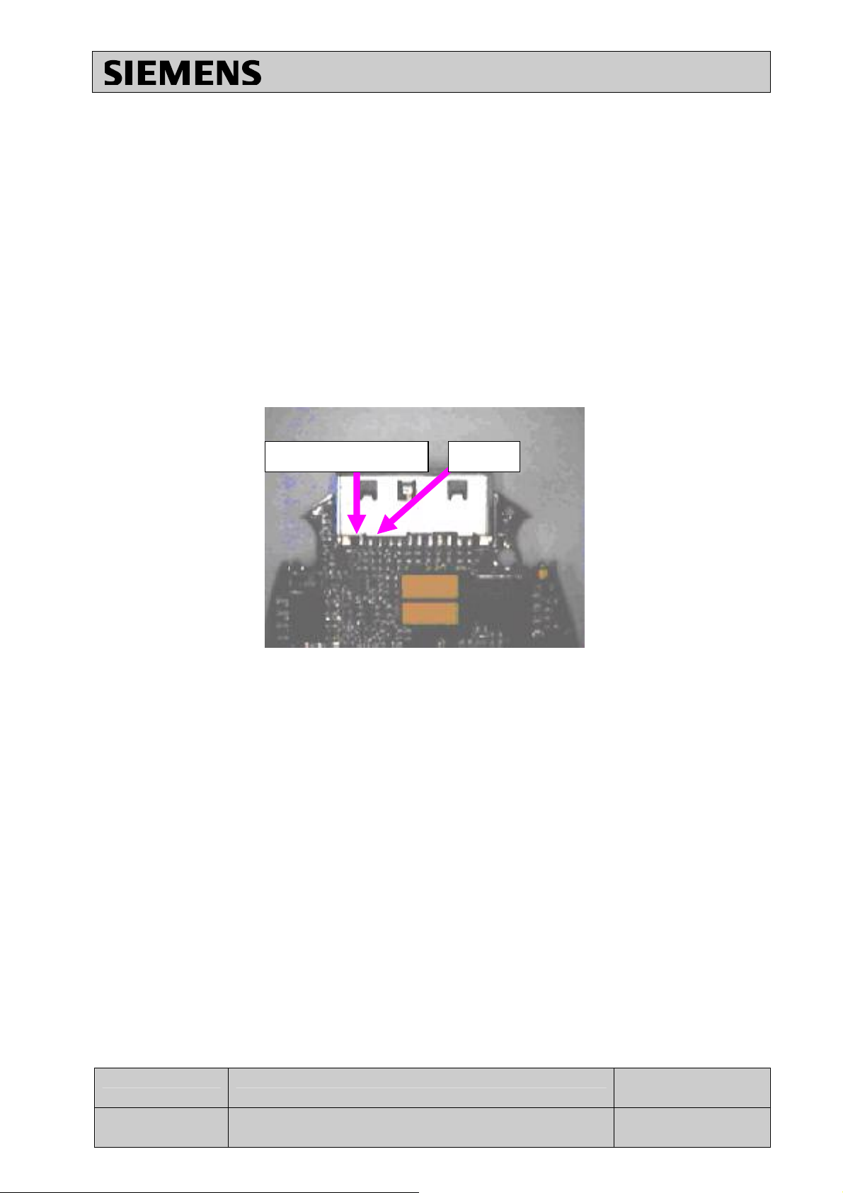
2.4.3 Drawing
Information and Communication Mobile
Mobile Phones
Figure 1: XELIBRI Board Battery Connector Placement
V 1.0 Page 7 of 14 ICM MP CCQ
GRM
X2 / X4 Company Confidential
Copyright 2003© Siemens AG
04/03
Page 8

Information and Communication Mobile
3 I/O CONNECTOR
3.1 Affected Units
3.1.1 Type: Xelibri
3.1.2 Affected IMEIs/Date Codes: All/All
3.1.3 Affected SW-versions: All
3.1.4 Fault Code for LSO reporting: NA
3.2 Fault Description
3.2.1 Fault Symptoms for customers:
Can not charge the handset
3.2.2 Fault Symptom on GSM tester:
This fault can not be detected with a GSM-Tester
3.2.3 Component Information
The connector (1660) is I/O connector (12 contacts) used the adapter charger.
The adapter charger uses the PIN1 for V_EXTERNAL _Charge and PIN2 GND
BOTTOM
Mobile Phones
V 1.0 Page 8 of 14 ICM MP CCQ
GRM
X2 / X4 Company Confidential
Copyright 2003© Siemens AG
04/03
Page 9

3.3 Priority:
………….Mandatory
………….Repair
………….Optional
………….Not Yet Defined
3.4 Repair document
3.4.1 Description of procedure
3.4.1.1 Diagnosis
Visually check pins for oxidation or deformity.
Visual inspection of the fittings and I/O pads solder joints (short circuit, leak, poor
brightness).
Measure pins to test points (Vexternal charge, GND) with a multimeter to check for
continuity
3.4.1.2 Repair by component change
1. Use a hot air nozzle to remove the defective connector.
Do not apply exessive heat and flow to avoid to destroy the adjoining solder
joints.
2. Level the solder joint on the pads (eventually add solder).
3. Secure new connector on the PCBA.
4. Reheat the solder on the pads with a fine-tipped soldering iron to allow the solder
to flow on th the connector’s pins.
3.4.1.3 Repair by SW-booting
Not possible!
3.4.1.4 Test
Plug the adapter charger and check if there is a signal on test point F611
(V_EXT_CHARGE)
Information and Communication Mobile
Mobile Phones
3.4.2 List of material
3.4.2.1 Components
I/O connector
Part-Number: Not yet defined !
V 1.0 Page 9 of 14 ICM MP CCQ
X2 / X4 Company Confidential
Copyright 2003© Siemens AG
GRM
04/03
Page 10
3.4.3 Jigs and Tools
V ext charge
GND
Hot air Blower
Soldering Iron
3.4.4 Special tools
Multimeter
3.4.5 Working materials
Solder wire
3.4.6 Drawing
Information and Communication Mobile
Mobile Phones
Figure 2: XELIBRI Board Battery Connector Placement
V 1.0 Page 10 of 14 ICM MP CCQ
GRM
X2 / X4 Company Confidential
Copyright 2003© Siemens AG
04/03
Page 11

Information and Communication Mobile
4 Other SMT components
4.1 Affected Units
4.1.1 Type: Xelibri
4.1.2 Affected IMEIs/Date Codes: All/All
4.1.3 Affected SW-versions: All
4.1.4 Fault Code for LSO reporting: NA
4.2 Fault Description
4.2.1 Fault Symptoms for customers:
Normaly no special complain from customer. Desoldered or damaged components during
a connector rework.
4.2.2 Fault Symptom on GSM tester:
This fault can not be detected with a GSM-Tester
4.2.3 Component Information
Mobile Phones
Position Component Type Order No. Value / Labelling
2012 Capacitor Not defined yet TAJA226K010S
7600 Charge Chip Not defined yet ST3S01PHD-TR
3632 Resistor Not defined yet RL1206JR-070R24
3642 Resistor Not defined yet RC0402JR-07330K
3643 Resistor Not defined yet RC0402JR-07220K
3655 Resistor Not defined yet RC0402JR-07330K
3656 Resistor Not defined yet RC0402JR-07220K
3540 Resistor Not defined yet RC0402JR-07120R
6630 Diode Not defined yet BZD27-C15
V 1.0 Page 11 of 14 ICM MP CCQ
GRM
X2 / X4 Company Confidential
04/03
Copyright 2003© Siemens AG
Page 12

4.3 Priority:
………….Mandatory
………….Repair
………….Optional
………….Not Yet Defined
4.4 Repair document
4.4.1 Description of procedure
4.4.1.1 Diagnosis
Visual inspection of the solder joints (bad soldering, poor brightness, no joint, bad
placement, no component).
4.4.1.2 Repair by component change
1. Use a hot air nozzle to remove the charge chip (pos. 7600) and the zener diode
(pos. 6630) and a fine-tipped soldering iron for the other components.
2. Level the solder joint on the pads (eventually add solder).
3. Peplace a new component on the pads.
4. Reheat the solder on the pads with a fine-tipped soldering iron to allow the solder
to flow on the contacts (eventually add solder with a solder wire).
4.4.1.3 Repair by SW-booting
Not possible!
4.4.1.4 Test
Measure the electrical value by applying a multimeter on the pads.
Or the charge chip, plug the charger and check the stoke running on the LCD.
Information and Communication Mobile
Mobile Phones
4.4.2 List of material
4.4.2.1 Components
See above.
4.4.2.2 Jigs and Tools
Hot air Blower
Soldering Iron
V 1.0 Page 12 of 14 ICM MP CCQ
X2 / X4 Company Confidential
Copyright 2003© Siemens AG
GRM
04/03
Page 13

4.4.3 Special tools
Multimeter
4.4.4 Working materials
Solder wire
4.4.5 Drawing
See chapter 6. PCB overview.
5 TEST POINTS LOCATION
Information and Communication Mobile
Mobile Phones
Vext charge
TP F611
V 1.0 Page 13 of 14 ICM MP CCQ
GRM
X2 / X4 Company Confidential
Copyright 2003© Siemens AG
04/03
Page 14

6 PCB OVERVIEW
Information and Communication Mobile
Mobile Phones
V 1.0 Page 14 of 14 ICM MP CCQ GRM
X2 / X4 Company Confidential
Copyright 2003© Siemens AG
01/03
 Loading...