

Page 1
Information and Communication Mobile
Mobile Phones
Level 2
Repair
Manual
XELIBRI-X2
Issue Date Author Description
0.9 11.03.02 Noblet First release
1.0 17.04.03 Lerner Layout update and 1st official release
1.1 22.05.03 Lerner Update on page 12: different antennas for X2 and X4
V 1.1 Page 1 of 17 ICM MP CCQ GRM
X2
Company Confidential
Copyright 2003© Siemens AG
05/03
Page 2

Information and Communication Mobile
Mobile Phones
Table of Contents:
1 TECHNICAL FEATURES OF THE XELIBRI ___________________________3
2 MOBILE SOFTWARE PROGRAMMING ______________________________4
3 UNLOCKING PROCEDURE ________________________________________4
4 ACCESSORIES__________________________________________________4
5 BATTERY INFORMATION _________________________________________4
5.1 label making____________________________________________________4
5.2 Charging time: __________________________________________________5
5.3 Charging procedure: _____________________________________________5
6 EXPLODED VIEW________________________________________________7
7 DISASSEMBLY PROCESS ________________________________________8
8 ASSEMBLY PROCESS __________________________________________11
9 TOOLS DESCRIPTION___________________________________________15
10 IMEI ACCES ___________________________________________________16
11 IMEI LABEL DESCRIPTION_______________________________________17
V 1.1 Page 2 of 17 ICM MP CCQ GRM
X2
Company Confidential
Copyright 2003© Siemens AG
05/03
Page 3
Information and Communication Mobile
1 TECHNICAL FEATURES OF THE XELIBRI
Feature Description
Frequency
Power
Antenna
Telephony
SMS
SIM Appl. Tool Kit
Keypad
Display
Illumination
Physical Details
Interfaces
Battery type
Charging
Melody
Phone Book
CPHS
Text input
Silent Alert
Phone No. Memory
Voice Recognition
Echo cancellation
Noise reduction
EGSM-900
GSM-1800
EGSM-900: Class 4 (2 W)
GSM-1800: Class 1 (1 W)
Integrated, built in patch antenna
SAR for Lunar <= 1. W/kg / Target 0.8 W/kg in 1 g and 0.7 W/kg target 0.5 W/kg
in 10 g
SAR for Jedi <= 1.2 W/kg / Target 0.8 W/kg in 1 g and 0.9 W/kg target 0.5 W/kg
in 10 g.
Coding RPE/LPC with LTP
HR, FR, EFR
Class 0, 1, 2
GSM TS 7.05 Short Message MT / MO
Cell Broadcast
Concatenated Messages / Picture Messages
refer to chapter Fehler! Verweisquelle konnte nicht gefunden werden.
0 to 9; *; #
4-contact navigation element (2 soft keys + up / down)
refer to MMI specification
refer to MMI specification, 101 x 65 pixels B/W
Supported
Target weight: 80g
temperature range: Normal operation (acc. 3GPP TS 51.010-1): –10°C to +55°C
Storage: –40°C to +85°C
according to Siemens design specification
Slim Lumberg for accessory support
exchangeable Li-Ion
600 mAh
min 200h Standby and talk time of 3H30 at level 10 and DTX = off in EFR
max. 6 h for empty batteries (0 – 5% capacity)
charging of deeply discharged battery possible
Embedded: 15 polyphonic (32 voices)
SIM, 255 records (SIM dependent)
ADN, FDN, SDN, MS-ISDN
Version 4.2 (no ALS)
T9 4.1
Vibration acceleration min 1g for front and rear measurements,
less than 11000 rotations/min
Mechanical noise of the component : loudness max 50 dBA @ 10 cm distance
30 numbers, for last number dialled, last number missed, last number received
all with date and time stamp
Speaker dependent: 20 tags via a “simple” UI
Supported
Supported
Mobile Phones
V 1.1 Page 3 of 17 ICM MP CCQ GRM
X2
Company Confidential
Copyright 2003© Siemens AG
05/03
Page 4

Information and Communication Mobile
Mobile Phones
2 MOBILE SOFTWARE PROGRAMMING
See the Software Update Manual.
3 UNLOCKING PROCEDURE
Not appilcable.
4 ACCESSORIES
The only available accessory is the standard charger:
Is designed by Siemens according to specification “ Charger for L55 series – version
03”Spec Ref: DIS 10506; date: 17/04/02 from Siemens AG ICM MP PO2 KLF32
The Standard Charger is only available in 3 country versions: UK, EU, China.
5 BATTERY INFORMATION
5.1 label making
- Customer Part Number: The label artwork will have the customer part no. shown as
follows :
Siemens part number: V30145-K1310-X267
The product index number, which signifies battery version, shall be printed after the
CELLon part number.
The mass product index number is 3.
-Tracking Code: Each battery will be marked with a unique code as follows :
YYYYMMDD ABCXXXX
Where YYYYMMDD = The battery manufacturing date.
A = the line number
B = the shift number ( A,C day shift: B,D, night shift)
C= serial number from A to Z
XXXX = is a sequence number.
- The country of origin of the cell shall be printed on the label.
Also after cell origin country shall be printed in brackets, S for Sanyo and T for
Toshiba, to denote cell supplier.
V 1.1 Page 4 of 17 ICM MP CCQ GRM
X2
Company Confidential
Copyright 2003© Siemens AG
05/03
Page 5
Information and Communication Mobile
5.2 Charging time:
2-3 hours (as mentioned in the user guide).
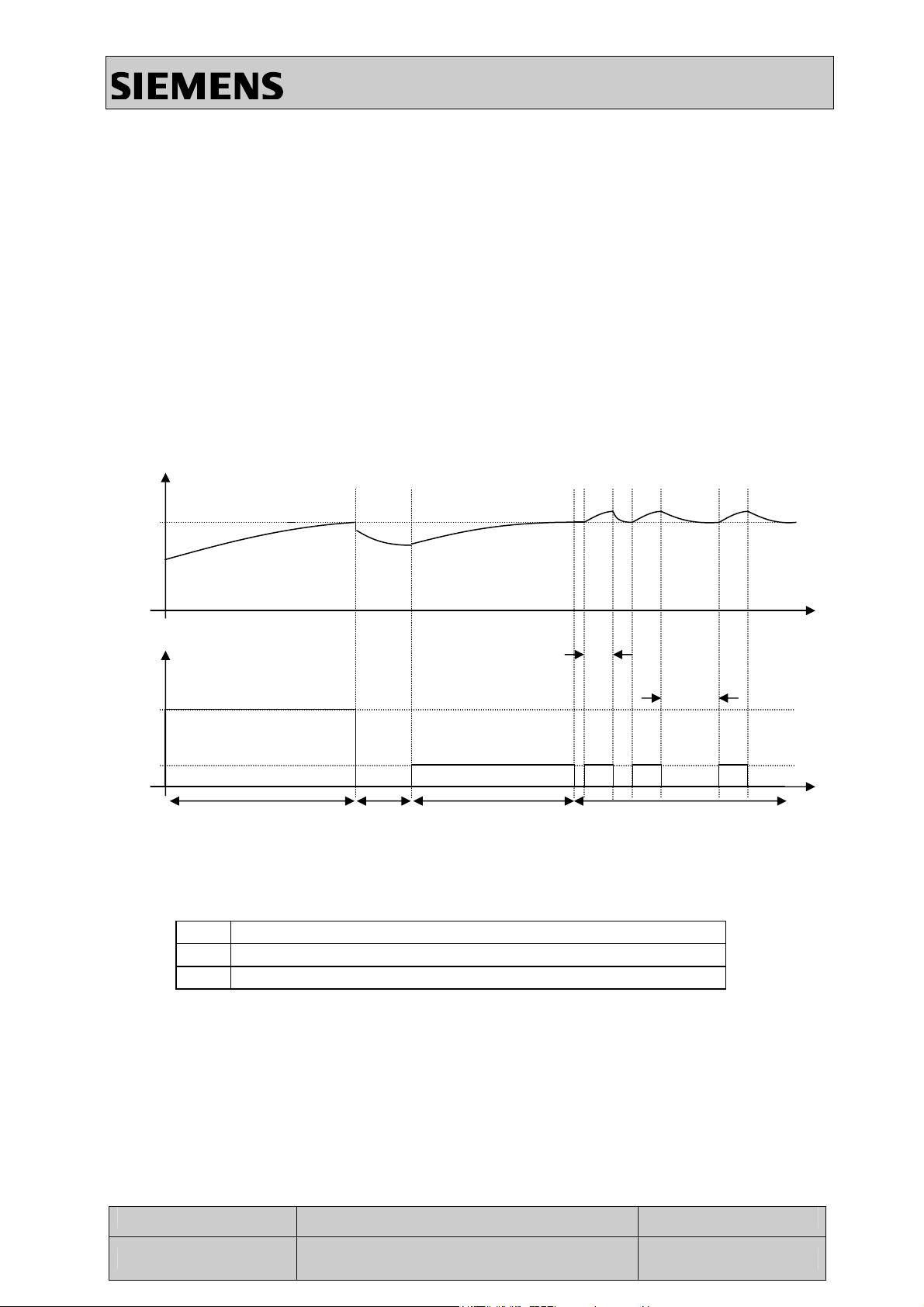
5.3 Charging procedure:
The “Two current steps charge ” is divided in 4 phases :
PH1 : Continuous Full Current.
PH2 : Wait Step.
PH3 : Continuous low current charge .
PH4 : Pulsed low current charge.
Battery voltage
Mobile Phones
C
Charge
Current
A
B
Phase 1 Phase 3 Phase 4
Phase 2
A High average current limited by the charger
B Continuous low current limited by the phone
C Release voltage of 4.2V +/-1%
Pulse 50ms
Trelax
Time
Time
V 1.1 Page 5 of 17 ICM MP CCQ GRM
X2
Company Confidential
Copyright 2003© Siemens AG
05/03
Page 6
Information and Communication Mobile
Mobile Phones
Phase 1: High average current charge
This phase occurs if the voltage is between 3.1V and 4.2 V +/- 1%.
During this step, the charge current is only limited by the charger, except if this
current is too high for the battery (refer to Annex13 for further explanations on this
current limit).
As some of the SIEMENS chargers delivers a high current compared to the
capacity of the battery, it’s necessary to detect too high a current and to directly go
through “continuous low current charge”. If this is not implemented, some
customers could have their talk time and standby time shortly and drastically
reduced after few charges. In order to prevent this risk, it’s necessary to measure
the current at the beginning of this “high average current charge” phase and to go
to next step if this current is too high.
The phase 1 ends when the battery voltage is 4.2V +/-1%. At the end of this
phase, Wait step begins.
Phase 2: Wait Step
This phase begins at the end of the phase 1 and is a wait step during which the
charge is stopped.
It is used to let the cell voltage decrease and avoid random transitions.
This timer is set to 4 seconds.
Phase 3:Continuous low current charge
For any charger, the charge current is limited between 100mA and 200mA, until the cell’s voltage reaches
4.2 Volts +/-1% for the second time (first time during phase 1). At the end of this phase, the Pulsed low
current charge phase begins.
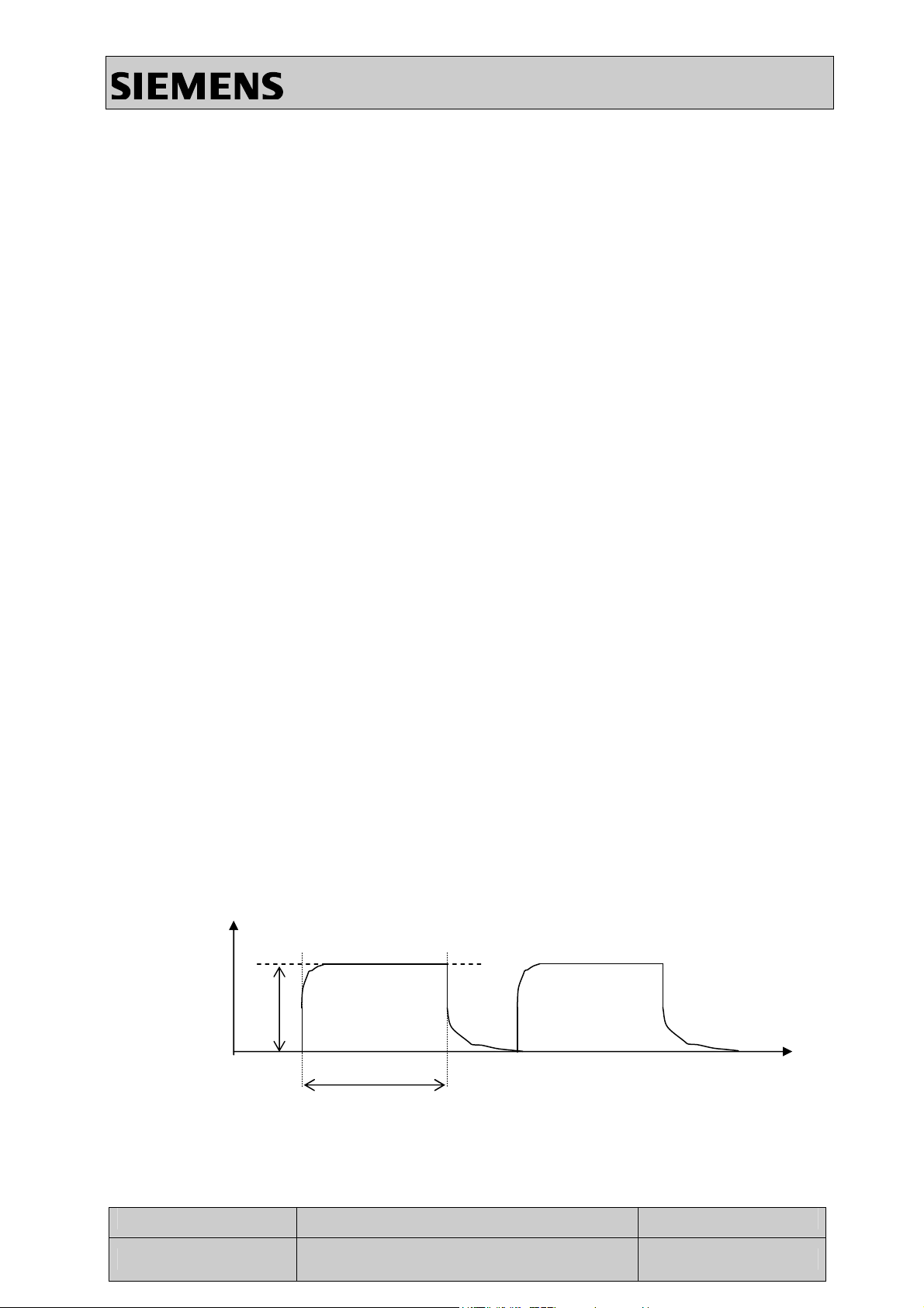
Phase 4: Pulsed low current charge
This phase begins at the end of the phase 3. The phase is applied endlessly
The current is applied for 50 ms. The next pulse is applied as soon as the battery
voltage goes down to 4.2V +/-1%.
With any switch mode chargers, the pulse has the following profile :
I
I
T
1
time
Imax = 200 mA T1typ = 50 ms
T1 max = 52 ms
V 1.1 Page 6 of 17 ICM MP CCQ GRM
X2
Company Confidential
Copyright 2003© Siemens AG
05/03
Page 7

6 EXPLODED VIEW
Spare parts level 2,5
No Order no. Description
5 Not yet defined Front housing
14 Not yet defined Ring rockerkey
3 Not yet defined Microphone
34 Not yet defined Earpiece assy
29 Not yet defined Window IMD assy
4 Not yet defined Front block foil
33 Not yet defined Keypad
35 Not yet defined LCD assy
44 Not yet defined S128 PCB assy
31 Not yet defined S128 antenna lunar
39 Not yet defined Vibrator
32 Not yet defined Chassis assy
18 Not yet defined Lumberg gasket
10 Not yet defined Lumberg door
40 Not yet defined Battery
23 Not yet defined Screw Torx+ 1.8 x 5
30 Not yet defined Rear housing assy
Information and Communication Mobile
Mobile Phones
V 1.1 Page 7 of 17 ICM MP CCQ GRM
X2
Company Confidential
Copyright 2003© Siemens AG
05/03
Page 8

Information and Communication Mobile
7 DISASSEMBLY PROCESS
Unclip the rear housing assy
Mobile Phones
Unclip the battery
Unclip the Lumberg door
Unscrew 6 self taping screws torx RF 1.8 X 5.0
With a manual screwdriver
Remove the chassis assy
Unclip the Lumberg gasket
V 1.1 Page 8 of 17 ICM MP CCQ GRM
X2
Company Confidential
Copyright 2003© Siemens AG
05/03
Page 9

Information and Communication Mobile
Remove the foil with tweezers
Remove the vibrator with tweezers
Mobile Phones
Remove the PCB with antenna assy
Unclip the antenna assy
Remove the keypad spring connector with tweezers
V 1.1 Page 9 of 17 ICM MP CCQ GRM
X2
Company Confidential
Copyright 2003© Siemens AG
05/03
Page 10

Information and Communication Mobile
Remove the LCD assy with tweezers
Remove the microphone
Mobile Phones
Remove the keypad assy
Remove the black foil with tweezers
Turn the front housing . The window and the ring rocker key
fall down
V 1.1 Page 10 of 17 ICM MP CCQ GRM
X2
Company Confidential
Copyright 2003© Siemens AG
05/03
Page 11

Information and Communication Mobile
Remove the earpiece with tweezers
8 ASSEMBLY PROCESS
Mobile Phones
Take a front housing
Put a ring rocker key in the front
Put a window assy
( for a new part remove the protection foil on the inner side
of the window )
V 1.1 Page 11 of 17 ICM MP CCQ GRM
X2
Company Confidential
Copyright 2003© Siemens AG
05/03
Page 12

Information and Communication Mobile
Assembly Mark
Take an earpiece. Remove the protection foil and put it in the
front. ( Take care to the earpiece orientation )
Put a black foil in the front
Mobile Phones
Put a keypad assy in the front
Take a LCD assy .
( for a new part remove the protection foil on the LCD )
Blow the dust on the window and on the LCD with a ionising gun
Put a LCD assy in the front housing
Move the foil with LEDs in their location
V 1.1 Page 12 of 17 ICM MP CCQ GRM
X2
Company Confidential
Copyright 2003© Siemens AG
05/03
Page 13

Information and Communication Mobile
Put a microphone in place
( Take care to the two spring contacts )
For a new keypad
Remove the protection foil behind the keypad spring connector
Mobile Phones
Fold up the foil of the keypad and stick the connector
( Take care to the spring contacts )
Take a PCB and an antenna assy
Clip the antenna assy on the PCB
Attention: The antenna for X4 is different to the X2
antenna !!! The X4 antenna is marked with a white
sticker whereas the X2 antenna is marked with a blue
sticker. Do not mix up the antennas this will cause
radio problems.
Put the PCB in place
Take a chassis assy
Take a vibrator and insert it in place
( Take care to the two spring contacts )
V 1.1 Page 13 of 17 ICM MP CCQ GRM
X2
Company Confidential
Copyright 2003© Siemens AG
05/03
Page 14

Information and Communication Mobile
Put the chassis, insert at first the antenna side
and shut down on the product
Screw 6 self taping screws torx RF 1.8 X 5.0
With a manual screwdriver
Mobile Phones
Take a Lumberg door
Insert the Lumberg door clip on the foil
Assembly Mark
Take a gasket ,insert the gasket on the Lumberg door
(Take care to the gasket orientation )
Insert a battery
V 1.1 Page 14 of 17 ICM MP CCQ GRM
X2
Company Confidential
Copyright 2003© Siemens AG
05/03
Page 15

Information and Communication Mobile
Take a rear housing assy ,
insert at first the Lumberg door side
and shut down on the product
Clip the rear housing assy
Insert the Lumberg door in the Lumberg connector
Mobile Phones
9 TOOLS DESCRIPTION
RF 1.8x5.0 Torx manual screwdriver__________________
Tweezers________________________________________
ESD protection bracelet_ ___________________
V 1.1 Page 15 of 17 ICM MP CCQ GRM
X2
Company Confidential
Copyright 2003© Siemens AG
05/03
Page 16

Information and Communication Mobile
Ionising gun ____________________________
10 IMEI ACCES
Dial : * # 06 #
Mobile Phones
V 1.1 Page 16 of 17 ICM MP CCQ GRM
X2
Company Confidential
Copyright 2003© Siemens AG
05/03
Page 17

11 IMEI LABEL DESCRIPTION
Information and Communication Mobile
Mobile Phones
V 1.1 Page 17 of 17 ICM MP CCQ GRM
X2
Company Confidential
Copyright 2003© Siemens AG
05/03
 Loading...