

Page 1

Information and Communication Mobile
Mobile Phones
XELIBRI X1
LEVEL 2.5
REPAIR DOCUMENTATION
V 1.0
V1.0 Page 1 of 23 ICM MP CCQ GRM
Xelibri 1 Company Confidential 03/2003
Page 2

Information and Communication Mobile
Mobile Phones
TABLE OF CONTENTS:
INTRODUCTION..........................................................................................................................................3
1
2 BATTERY CONNECTOR............................................................................................................................4
3 SIM CARD READER....................................................................................................................................7
4 SYSTEM CONNECTOR ............................................................................................................................10
5 RTC BATTERY ...........................................................................................................................................15
6 KEYMAT CONNECTOR...........................................................................................................................18
7 DISPLAY LEDS...........................................................................................................................................21
V1.0 Page 2 of 23 ICM MP CCQ GRM
Xelibri 1 Company Confidential 03/2003
Page 3
Information and Communication Mobile
Mobile Phones
1 Introduction
The Xelibri X1 is a dual band (EGSM900/GSM1800) handportable phone with a Li-Ion
battery. There are three different colours and six different variants. The colours are White,
Smoke and Champaign with either Latin key pat or Chinese Stroke key pat.
Partnumber on IMEI label:
Xelibri X1: S30880-S9230-Axxx,
where xxx may be any number from 100, 101, 102...
This manual is intended to help you carry out repairs on level 2.5, meaning limited
component repairs. Failure highlights are documented and should be repaired in the local
workshops.
It must be noted that all repairs have to be carried out in an environment set up according to
the ESD (Electrostatic Discharge Sensitive Devices) regulations defined in international
standards.
If you have any questions regarding the repair procedures or technical questions about the
spare parts do not hesitate to contact our technical support team in Kamp-Lintfort, Germany:
Tel.: +49 2842 95 4666
Fax: +49 2842 95 4302
E-mail: ST-Support@klf.siemens.de
V1.0 Page 3 of 23 ICM MP CCQ GRM
Xelibri 1 Company Confidential 03/2003
Page 4

Information and Communication Mobile
Mobile Phones
2 Battery Connector
2.1 Affected Units
2.1.1 Type: Xelibri X1
2.1.2 Affected IMEIs / Date Codes: All / All
2.1.3 Affected SW-Versions: All
2.2 Fault Description
2.2.1 Fault Symptoms for customers:
Mobile does not switch on.
No charging
2.2.2 Fault Symptom on GSM-Tester:
This fault cannot be detected with a GSM-Tester.
2.3 Priority:
p ........ Mandatory
x ........ Repair
p ........ Optional
p ........ Not Yet Defined
2.4 Repair Documentation
2.4.1 Description of procedure:
2.4.1.1 Diagnosis
Check the battery connector visually. Watch for oxidation and dry
joints!
V1.0 Page 4 of 23 ICM MP CCQ GRM
Xelibri 1 Company Confidential 03/2003
Page 5
Information and Communication Mobile
Mobile Phones
2.4.1.2 Repair by component change
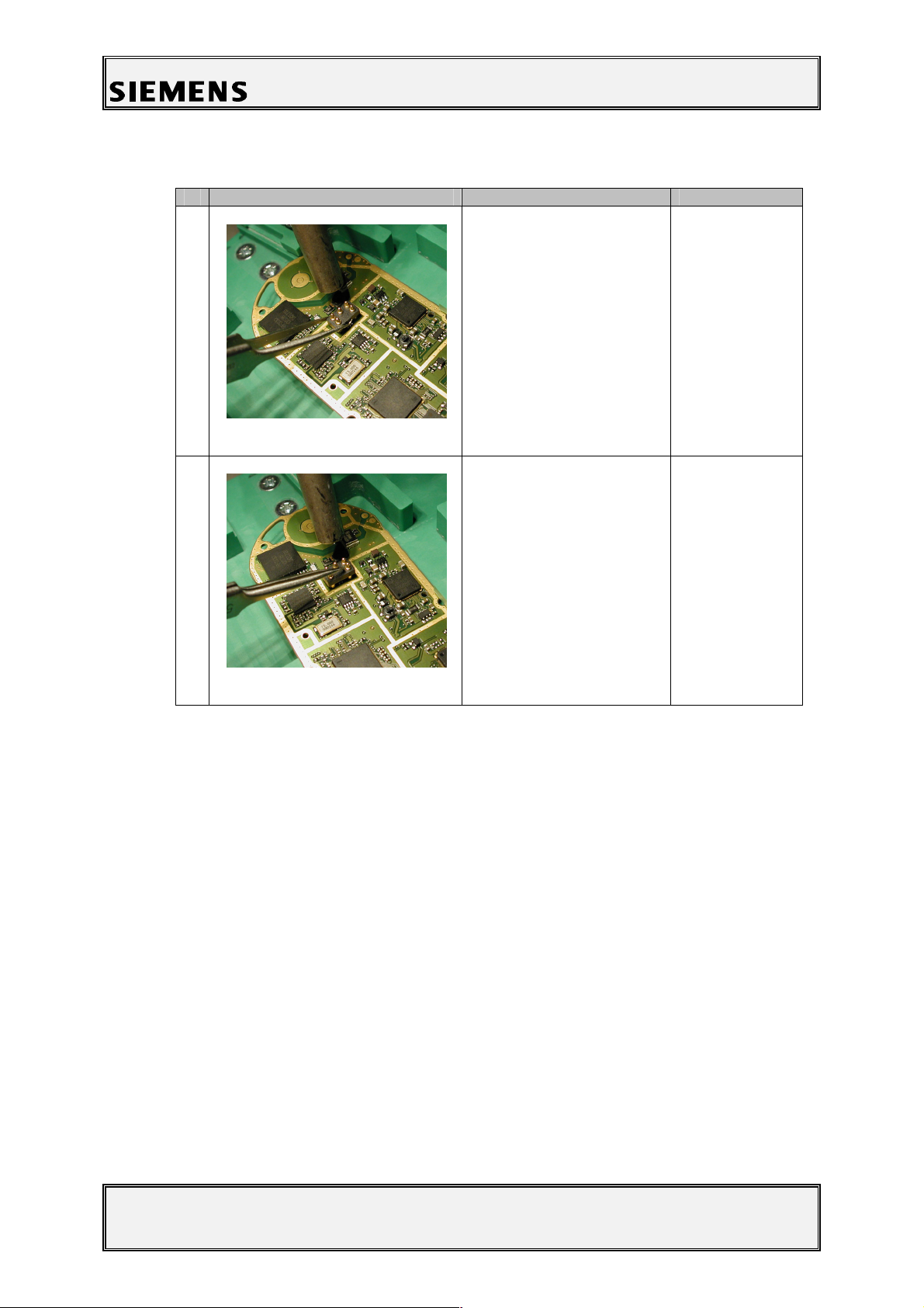
# Figure Instruction Note
1
Figure 2-1
Use a hot air blower to
remove the defective
battery connector.
Avoid excessive heat!
Watch surrounding
components!!
2
Figure 2-2
2.4.1.3 Repair by SW-Booting
Not possible!
2.4.1.4 Test
Retest the handset after the repair.
Re-solder the new
battery connector by
using a hot air blower.
Check that the
connector is straight and
exactly in right place.
2.4.2 List of needed material
2.4.2.1 Components
Battery connector pogo 3.3mm/5.2mm SMD
Part Number: Siemens code: xxx
2.4.2.2 Jigs and Tools
Hot air blower
Tweezers
Inspection lamp
V1.0 Page 5 of 23 ICM MP CCQ GRM
Xelibri 1 Company Confidential 03/2003
Page 6
Information and Communication Mobile
Mobile Phones
2.4.2.3 Special Tools
None
2.4.2.4 Working materials
Flux
Solder
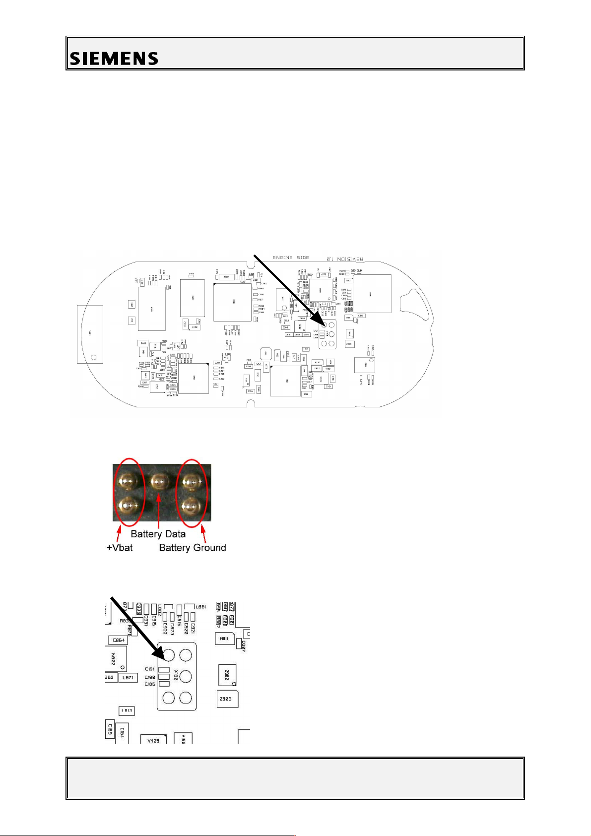
2.4.3 Drawings
Figure 1: Xelibri X1 board, battery connector side
Figure 2: Xelibri X1 battery connector pin description
Figure 3: Xelibri X1 battery connector placement (top view)
V1.0 Page 6 of 23 ICM MP CCQ GRM
Xelibri 1 Company Confidential 03/2003
Page 7
Information and Communication Mobile
Mobile Phones
3 SIM card reader
3.1 Affected Units
3.1.1 Type: Xelibri X1
3.1.2 Affected IMEIs / Date Codes: All / All
3.1.3 Affected SW-Versions: All
3.2 Fault Description
3.2.1 Fault Symptoms for customers:
Handset does not accept the SIM card.
3.2.2 Fault Symptom on GSM-Tester:
This fault cannot be detected with a GSM-Tester.
3.3 Priority:
p ........ Mandatory
x
p
........ Repair
........ Optional
p ........ Not Yet Defined
3.4 Repair Documentation
3.4.1 Description of procedure:
3.4.1.1 Diagnosis
Check the status of the SIM card reader visually. Watch for oxidation
and dry solder joints.
V1.0 Page 7 of 23 ICM MP CCQ GRM
Xelibri 1 Company Confidential 03/2003
Page 8

Information and Communication Mobile
Mobile Phones
3.4.1.2 Repair by component change
# Figure Instruction Note
1
Figure 3-1
Use a hot air blower to
remove the defective
SIM card reader.
Avoid excessive heat!
Watch surrounding
components!!
2
Figure 3-2
3.4.1.3 Repair by SW-Booting
Not possible!
3.4.1.4 Test
The functionality of the SIM card reader can be tested with the
following signals:
· Measure VSIM (2.75 V - 3.3 V) from capacitor R186. Voltage
· SIMCLK on V181 pin 1. This signal will only appear if a SIM
· SIMDATA on V181 pin 2. This signal will only appear if a SIM
Re-solder the new SIM
card reader by using a
hot air blower. Check
that the SIM card reader
is straight and exactly in
right place.
appears only for a short time if a SIM card is not inserted when
the phone is switched on, and when a SIM card is inserted,
present voltage should stay constantly approx. 2.9 V when the
power is on.
card is inserted and working. The Clock signal is not present
always, but will come in intervals.
card is inserted and working and when SIMCLK is present.
V1.0 Page 8 of 23 ICM MP CCQ GRM
Xelibri 1 Company Confidential 03/2003
Page 9

Information and Communication Mobile
Mobile Phones
3.4.2 List of needed material
3.4.2.1 Components
Generic SIM contact module SMD
Part Number: Siemens code: xxx
3.4.2.2 Jigs and Tools
Hot air blower
Tweezers
3.4.2.3 Special Tools
None
3.4.2.4 Working materials
Flux
Solder
3.4.3 Drawings
Figure 1: Xelibri X1 board, SIM card reader side
Figure 2: Pin order, top view (SIM connector)
CLK
RST
Vcc
6
3
2
5
1
4
DATA
Vpp (NC)
GND
V1.0 Page 9 of 23 ICM MP CCQ GRM
Xelibri 1 Company Confidential 03/2003
Page 10

Information and Communication Mobile
Mobile Phones
4 SYSTEM CONNECTOR
4.1 Affected Units
4.1.1 Type: Xelibri X1
4.1.2 Affected IMEIs / Date Codes: All / All
4.1.3 Affected SW-Versions: All
4.2 Fault Description
4.2.1 Fault Symptoms for customers:
Charging problems.
Problems with external loudspeaker or microphone
when using a car kit.
Problems with accessories connected at the system
connector.
Problems with SW booting.
4.2.2 Fault Symptom on GSM-Tester:
This fault cannot be detected with a GSM-Tester.
4.3 Priority:
p ........ Mandatory
x
p
........ Repair
........ Optional
p ........ Not Yet Defined
V1.0 Page 10 of 23 ICM MP CCQ GRM
Xelibri 1 Company Confidential 03/2003
Page 11

Information and Communication Mobile
Mobile Phones
4.4 Repair Documentation
4.4.1 Description of procedure:
4.4.1.1 Diagnosis
Check the system connector visually. Watch for dry joints!
4.4.1.2 Repair by component change
# Figure Instruction Note
1
Use a hot air blower to
remove the defective
system connector.
Avoid excessive heat!
Watch surrounding
components!
Figure 4-1
2
Figure 4-2
4.4.1.3 Repair by SW-Booting
Not possible!
4.4.1.4 Test
Charging problems can be discovered by measuring the voltage
between pins 1 (Power) and 2 (GND). Voltage should be between 5V
and 9,5V if system connector is working.
Re-solder the new
system connector by
using a hot air blower,
and a soldering iron if
necessary. Check that
the system connector is
straight and exactly in
right place.
V1.0 Page 11 of 23 ICM MP CCQ GRM
Xelibri 1 Company Confidential 03/2003
Page 12

Information and Communication Mobile
Mobile Phones
In order to detect an accessory when plugged into the system
connector, the following pins on the connector are used in the
detection scenario: POWER, TX/D+, RX/D-, DATA/CTS, CLK/DCD
and RTS. Table 1 shows the pins and their possible use in a detection
scenario.
Table 1: Accessory coding options
Pin No. Signal name Default level Default
direction
1 POWER L(Z) Off Open or charge source (Set by
2 GND GND -
3 TX/D+ H(Z) Out High/Low (Set by Phone)
4 RX/D- L(Z) In Open, Tx or high (Set by accessory)
5 DATA/CTS H(Z) In Open, Tx or low (Set by accessory)
6 RTS H(Z) In Open, Tx or low (Set by accessory)
7 CLK/DCD H(Z) In Open, Tx or low (Set by accessory)
Possible coding options
accessory)
The different coding options for the supported accessories can be
seen in Table 2.
Table 2: Accessory coding table
RX/D- DATA/CTS CLK/DCD RTS Description
OPEN OPEN OPEN OPEN Default: No accessory connected
TX/D+ GND OPEN TX/D+ Headset
TX/D+ GND GND TX/D+ Headset with PTT pressed
HIGH OPEN GND OPEN Car Kit portable
4.4.2 List of needed material
4.4.2.1 Components
System connector Female 12PIN SMD
Part Number: Siemens code: xxx
4.4.2.2 Jigs and Tools
Hot air blower
Soldering iron
Tweezers
V1.0 Page 12 of 23 ICM MP CCQ GRM
Xelibri 1 Company Confidential 03/2003
Page 13

Information and Communication Mobile
Mobile Phones
4.4.2.3 Special Tools
None
4.4.2.4 Working materials
Flux
Solder
4.4.3 Drawings
Figure 1: Xelibri X1 board, system connector side
V1.0 Page 13 of 23 ICM MP CCQ GRM
Xelibri 1 Company Confidential 03/2003
Page 14

Information and Communication Mobile
Mobile Phones
Table 3: Xelibri X1 system connector pin description
Pin Name IN/OUT Notes
1 POWER I Charging Current
2 GND Common GND
3 TX O Serial interface, used for Flash
programming and ITP commands
4 RX I Serial interface, used for Flash
programming and ITP commands
5 DATA/CTS I/O Serial interface, used for AT-
commands.
Data line for accessory bus.
Use as CTS in data operation.
Used for accessory detection
6 RTS I Used for accessory detection
7 CLK/DCD I/O Serial interface, used for AT-
commands.
Used for accessory detection
8 Audio L O Dual -ended (other end is Audio R)
output for external receiver (mono)
9 Audio_Ref/V
PP
I Used for 12V flash programming
voltage
10 Audio R O Dual -ended (other end is Audio L)
output for external receiver (mono)
11 Gnd_Micro GND external microphone
12 Micro I Input for external microphone
Table 4: Lumberg signal levels
Pin no. Signal name Level Min [V] Max [V]
3 TX/D+ VOH VOL 2.17 0 3.00 0.20
4 RX/D- VIH VIL 2.10 0 3.60 0.48
5 DATA/CTS VIH VIL
V
OH VOL
2.10 0 2.17 0 3.30 0.46 3.00 0.42
6 RTS VIH VIL 2.10 0 3.30 0.46
7 CLK/DCD VIH VIL 2.10 0 3.30 0.46
V1.0 Page 14 of 23 ICM MP CCQ GRM
Xelibri 1 Company Confidential 03/2003
Page 15

Information and Communication Mobile
Mobile Phones
5 RTC BATTERY
5.1 Affected Units
5.1.1 Type: Xelibri X1
5.1.2 Affected IMEIs / Date Codes: All / All
5.1.3 Affected SW-Versions: All
5.2 Fault Description
5.2.1 Fault Symptoms for customers:
The clock is reset when power is switched off.
5.2.2 Fault Symptom on GSM-Tester:
This fault cannot be detected with a GSM-tester.
5.3 Priority:
p ........ Mandatory
x
p
........ Repair
........ Optional
p ........ Not Yet Defined
5.4 Repair Documentation
5.4.1 Description of procedure:
5.4.1.1 Diagnosis
Check the RTC battery visually. Watch for dry joints!
V1.0 Page 15 of 23 ICM MP CCQ GRM
Xelibri 1 Company Confidential 03/2003
Page 16

Information and Communication Mobile
Mobile Phones
5.4.1.2 Repair by component change
# Figure Instruction Note
1
Figure 5-1
Use a hot air blower to
remove the defective
RTC battery. Avoid
excessive heat!
Watch surrounding
components!
2
Figure 5-2
5.4.1.3 Repair by SW-Booting
5.4.1.4 Test
Not possible!
Retest the handset after the repair.
Resolder the new RTC
battery by using a hot air
blower and a soldering
iron if necessary. Check
that the RTC battery is
exactly in right place.
Watch surrounding
components!
5.4.2 List of needed material
5.4.2.1 Components
RTC-BATTERY SMD VA6
Part Number: Siemens code: xxx
V1.0 Page 16 of 23 ICM MP CCQ GRM
Xelibri 1 Company Confidential 03/2003
Page 17

Information and Communication Mobile
Mobile Phones
5.4.2.2 Jigs and Tools
Hot air blower
Soldering iron
Tweezers
5.4.2.3 Special Tools
None
5.4.2.4 Working materials
Flux
Solder
5.4.3 Drawings
Figure 1: Xelibri X1 board, RTC battery SMD VA6
Figure 2: Xelibri X1 RTC battery SMD placement (top view)
V1.0 Page 17 of 23 ICM MP CCQ GRM
Xelibri 1 Company Confidential 03/2003
Page 18

Information and Communication Mobile
Mobile Phones
6 KEY PAT CONNECTOR
6.1 Affected Units
6.1.1 Type: Xelibri X1
6.1.2 Affected IMEIs / Date Codes: All / All
6.1.3 Affected SW-Versions: All
6.2 Fault Description
6.2.1 Fault Symptoms for customers:
The key pat does not work.
6.2.2 Fault Symptom on GSM-Tester:
This fault cannot be detected with a GSM-tester.
6.3 Priority:
p ........ Mandatory
x
p
........ Repair
........ Optional
p ........ Not Yet Defined
6.4 Repair Documentation
6.4.1 Description of procedure:
6.4.1.1 Diagnosis
Check the Connector visually. Watch for dry joints!
V1.0 Page 18 of 23 ICM MP CCQ GRM
Xelibri 1 Company Confidential 03/2003
Page 19

Information and Communication Mobile
Mobile Phones
6.4.1.2 Repair by component change
# Figure Instruction Note
1
Figure 6-1
Use a hot air blower to
remove the defective
keymat connector. Avoid
excessive heat!
Watch surrounding
components!
2
6.4.1.3 Repair by SW-Booting
6.4.1.4 Test
Not possible!
Retest the handset after the repair.
6.4.2 List of needed material
Resolder the new
keymat connector by
using a hot air blower
and a soldering iron if
necessary. Check that
the keymat connector is
straight and exactly in
right place. Watch
surrounding
components!
6.4.2.1 Components
SMD CONNECTOR 20PIN MALE
Part Number: Siemens code: xxx
6.4.2.2 Jigs and Tools
Hot air blower
Soldering iron
Tweezers
V1.0 Page 19 of 23 ICM MP CCQ GRM
Xelibri 1 Company Confidential 03/2003
Page 20

Information and Communication Mobile
Mobile Phones
6.4.2.3 Special Tools
None
6.4.2.4 Working materials
Flux
Solder
6.4.3 Drawings
Figure 1: Xelibri X1 board, key pat connector
V1.0 Page 20 of 23 ICM MP CCQ GRM
Xelibri 1 Company Confidential 03/2003
Page 21

Information and Communication Mobile
Mobile Phones
7 Display LEDs
7.1 Affected Units
7.1.1 Type: Xelibri X1
7.1.2 Affected IMEIs / Date Codes: All / All
7.1.3 Affected SW-Versions: All
7.2 Fault Description
7.2.1 Fault Symptoms for customers:
7.2.2 Fault Symptom on GSM-Tester:
7.3 Priority:
p ........ Mandatory
x
p
........ Repair
........ Optional
p ........ Not Yet Defined
7.4 Repair Documentation
7.4.1 Description of procedure:
Display LEDs are not lit.
This fault cannot be detected with a GSM-tester.
7.4.1.1 Diagnosis
Check the display LEDs visually. Watch for dry joints!
V1.0 Page 21 of 23 ICM MP CCQ GRM
Xelibri 1 Company Confidential 03/2003
Page 22

Information and Communication Mobile
Mobile Phones
7.4.1.2 Repair by component change
# Figure Instruction Note
1
Figure 7-1
Use a hot air blower to
remove the defective
display LED. Avoid
excessive heat!
Watch surrounding
components!
2
Figure 7-2
7.4.1.3 Repair by SW-Booting
7.4.1.4 Test
Re-solder the new
display LED by using a
hot air blower and a
soldering iron if
necessary. Watch
surrounding
components!
Not possible!
Retest the handset after the repair.
7.4.2 List of needed material
7.4.2.1 Components
LED COLOR WHITE SIDEFIRE 10mA 3.4V 3.1x1.2mm SMD
Part number: Siemens code: xxx
7.4.2.2 Jigs and Tools
Hot air blower
Soldering iron
V1.0 Page 22 of 23 ICM MP CCQ GRM
Xelibri 1 Company Confidential 03/2003
Page 23

Information and Communication Mobile
Mobile Phones
Tweezers
7.4.2.3 Special Tools
None
7.4.2.4 Working materials
Flux
Solder
7.4.3 Drawings
Figure 1: Xelibri X1 board, display LEDs side
Figure 2: Xelibri X1 display LEDs placement (top view)
V1.0 Page 23 of 23 ICM MP CCQ GRM
Xelibri 1 Company Confidential 03/2003
 Loading...