

Page 1
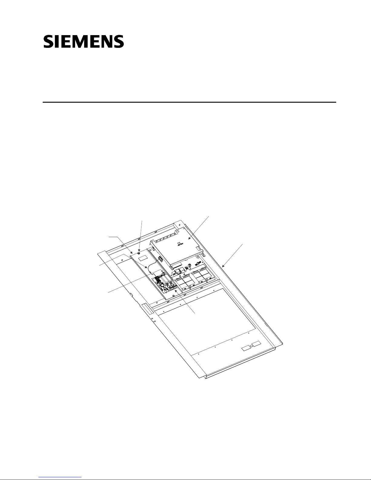
PMI REAR
COVER
INNER DOOR
2-POS
CONNECTOR
PLUG
CABLE
HARNESS
DIALER
BRACKET
LOCKNUTS
(2) REQ’D
DIALER
MODEL FCA2015-U1
INSTALLATION INSTRUCTIONS
Model XDACT-ASSY
Assembly
INTRODUCTION
The Model XDACT-ASSY is an optional assembly that can be mounted on the inner doors next to a
PMI-2 or a PMI-3, or in the second row of inner doors of CAB2 and CAB3.
Parts Supplied:
1) Dialer bracket, q’ty = 1
2) Locknuts, q’ty = 2
3) Cable harness, q’ty = 1
4) 2-pos connector plug, q’ty = 1
5) Instruction sheet
Figure 1 – Mounting the Dialer
A6V10807278_enUS_b Siemens Industry , Inc.
Building Technologies Division
Page 2
2
12-22 AWG
BLACK
12-22 AWG
RED
DIALER
FCA2015-U1
2-POS
CONNECTOR
PLUG
POWER
PSC-12
TB3
POSITION 2
X102
POSITION 2
Figure 2 – Power Connection to Dialer
INSTALLATION
1. Remove all system power before installation, first battery then AC. To power up, connect the
AC first, then the battery.
2. Mount the dialer bracket in either row 1 or row 2 of the inner door, using the two locknuts
provided.
3. Mount the dialer Model FCA2015-U1, P/N S54400-A63-A1, on the bracket using the four
screws provided with the Dialer.
4. Remove the plastic rear cover of the PMI by removing only the four screws.
5. Connect the cable harness provided to the PMI connector header and to the Dialer.
6. Plug the 2-pos connector provided into the dialer as shown in Figure 2. Use two 12-22 AWG
wires to connect it to the power supply. Connect the black wire from connector TB3 “Position
2” to the connector on the dialer X102 “Position 2”. See Figure 2.
7. Reinstall the PMI rear cover that was removed in Step 4.
8. Refer to the FCA2015-U1 DACT Installation Instructions, Document ID A6V10334254, for more
9. Apply power to the system.
10. Configure using Zeus programming tool.
information, including telephone connection wiring.
NOTE: See the Zeus Quick-Start Manual, P/N 315-033875, for details on programming.
11. Check for proper operation.
A6V10807278_enUS_b
Page 3

3
Cyber security disclaimer
Siemens products and solutions provide security functions to ensure the secure operation of building comfort,
fire safety, security management and physical security systems. The security functions on these products and
solutions are important components of a comprehensive security concept.
It is, however, necessary to implement and maintain a comprehensive, state-of-the-art security concept that
is customized to individual security needs. Such a security concept may result in additional site-specific
preventive action to ensure that the building comfort, fire safety, security management or physical security
system for your site are operated in a secure manner. These measures may include, but are not limited to,
separating networks, physically protecting system components, user awareness programs, defense in depth,
etc.
For additional information on building technology security and our offerings, contact your Siemens sales or
project department. We strongly recommend customers to follow our security advisories, which provide
information on the latest security threats, patches and other mitigation measures.
http://www.siemens.com/cert/en/cert-security-advisories.htm
A6V10807278_enUS_b
Page 4

Document ID A6V10807278_enUS_b P/N A5Q00069411
 Loading...