

Page 1
Ultrasonic Transducers
XCT-8
Operating Instructions 03/2010
Page 2

Safety Guidelines: Warning notices must be observed to ensure personal safety as well as that of
others, and to protect the product and the connected equipment. These warning notices are
accompanied by a clarification of the level of caution to be observed.
Qualified Personnel: This device/system may only be set up and operated in conjunction with this
manual. Qualified personnel are only authorized to install and operate this equipment in accordance with
established safety practices and standards.
Unit Repair and Excluded Liability:
• The user is responsible for all changes and repairs made to the device by the user or the user’s
agent.
• All new components are to be provided by Siemens Milltronics Process Instruments Inc.
• Restrict repair to faulty components only.
• Do not reuse faulty components.
Warning: Cardboard shipping package provides limited humidity and moisture protection. This product
can only function properly and safely if it is correctly transported, stored, installed, set up, operated, and
maintained.
This product is intended for use in industrial areas. Operation of this equipment in a residential area
may cause interference to several frequency based communications.
Note: Always use product in accordance with specifications.
Copyright Siemens Milltronics Process
Disclaimer of Liability
Instruments Inc. 2010. All Rights Reserved
This document is available in bound version and in
electronic version. We encourage users to purchase
authorized bound manuals, or to view electronic
versions as designed and authored by Siemens
Milltronics Process Instruments Inc. Siemens
Milltronics Process Instruments Inc. will not be
responsible for the contents of partial or whole
reproductions of either bound or electronic versions.
While we have verified the contents of this
manual for agreement with the instrumentation
described, variations remain possible. Thus we
cannot guarantee full agreement. The contents
of this manual are regularly reviewed and
corrections are included in subsequent editions.
Please check the website shown below for the
latest manual revisions.
We welcome all suggestions for improvement.
Technical data subject to change.
MILLTRONICS®is a registered trademark of Siemens Milltronics Process Instruments Inc.
Contact SMPI Technical Publications European Authorized Representative
at the following address:
Technical Publications Siemens AG
Siemens Milltronics Process Instruments Inc. Industry Sector
1954 Technology Drive, P.O. Box 4225 76181 Karlsruhe
Peterborough, Ontario, Canada, K9J 7B1 Deutschland
Email: techpubs.smpi@siemens.com
• For a selection of Siemens Milltronics level measurement manuals, go to:
www. siemens.com/level. Choose Instructions and Manuals under the More Info list.
• For a selection of Siemens Milltronics weighing manuals, go to:
www. siemens.com/weighing. Choose Support, and then Manuals / Operating Instructions.
© Siemens Milltronics Process Instruments Inc. 2010
Page 3
Introduction
This product is intended for use in industrial areas. Operation of this
equipment in a residential area may cause interference to several
frequency based communications.
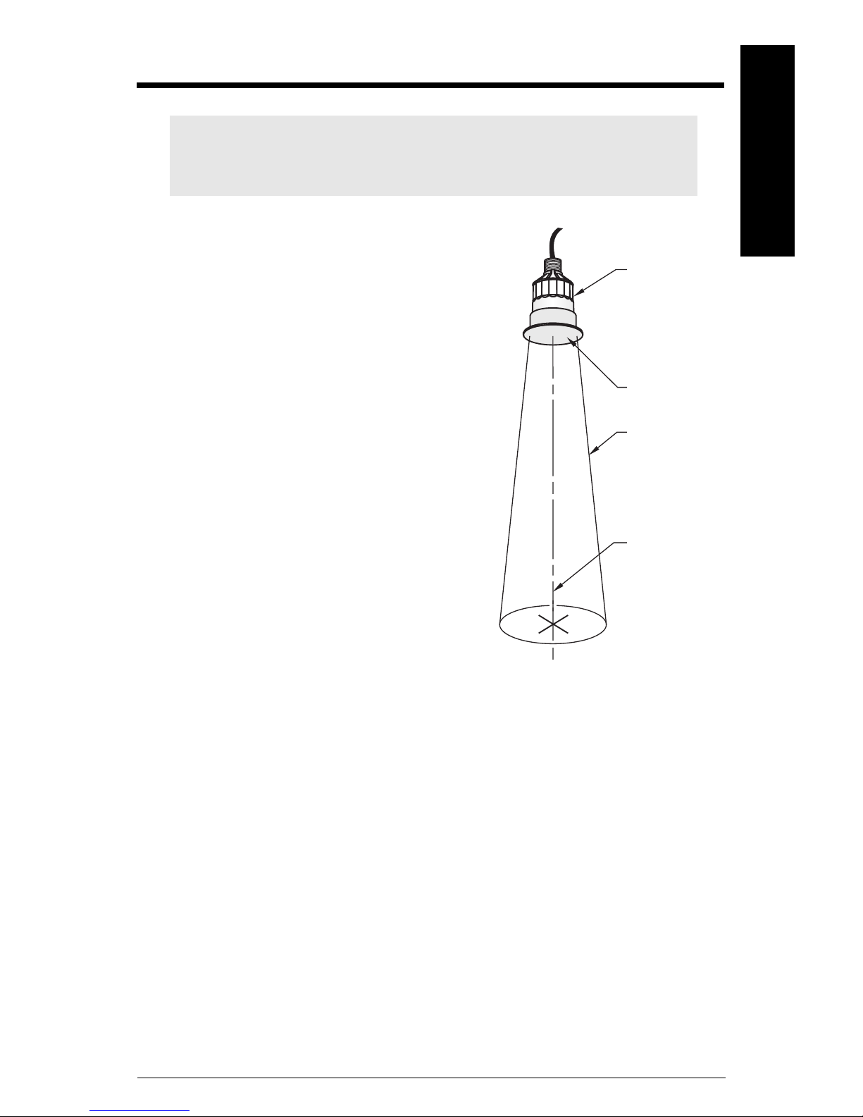
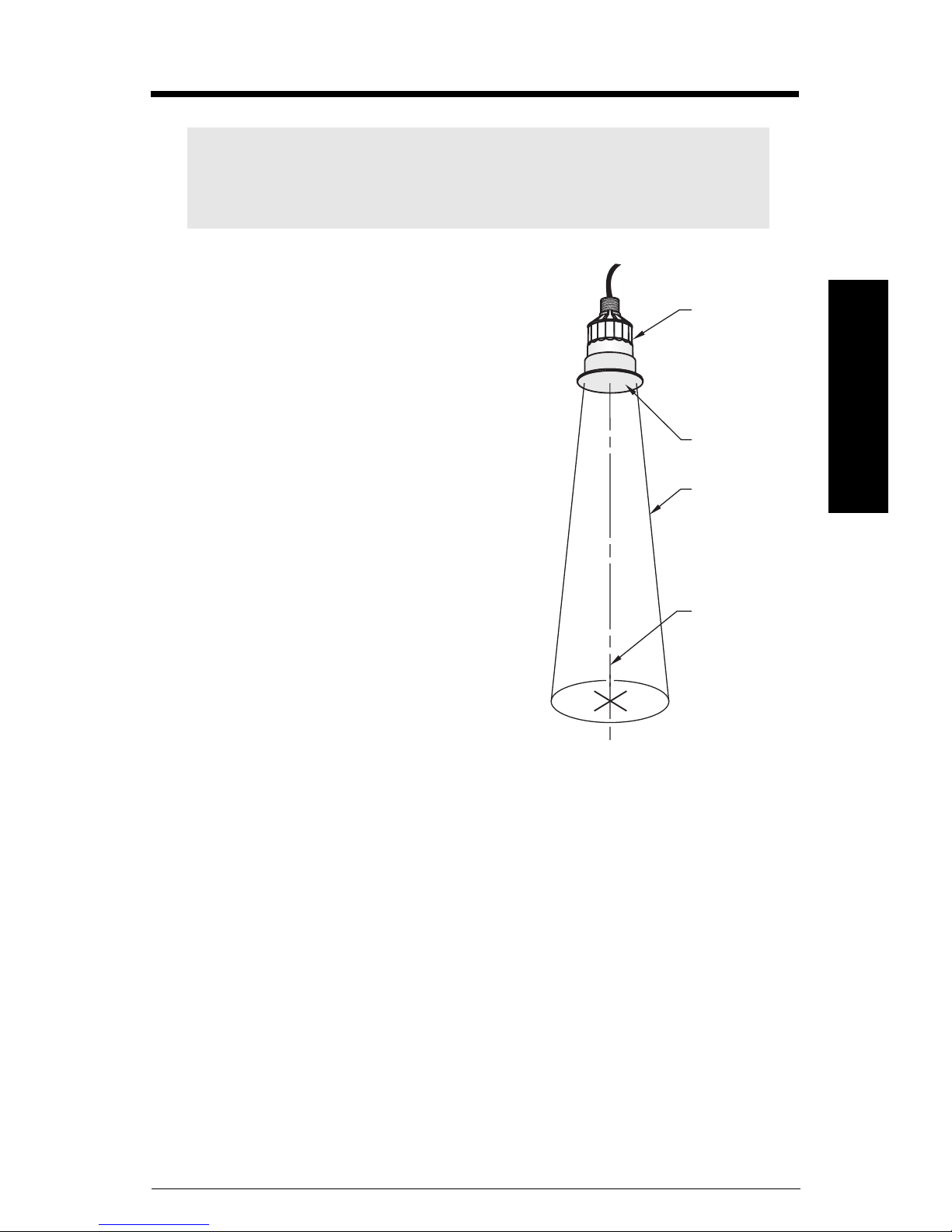
The Echomax XCT-8 transducer operates in
association with Siemens Milltronics ultrasonic
level monitoring products.
The transducer converts electrical pulses
provided by the transceiver to ultrasonic pulses
used for measurement and converts the ultrasonic
echoes back into an electrical signal. The signal is
interpreted by the Siemens Milltronics transceiver
using the patented Sonic Intelligence® algorithms
developed by Siemens Milltronics. The ultrasonic
pulse reduces in power by – 3 dB in a 12° cone
from the transducer face. Keep objects out of this
cone path to reduce the chance of false echoes
being recorded.
English
transducer
transducer
face
– 3 dB
boundary
The XCT-8 transducer incorporates an integral
temperature sensor that reports the ambient
temperature to the transceiver. The connection is
transparent because the ultrasonic and
temperature components of the transducer use
the same leads. This ensures that the Siemens
Milltronics transceiver can automatically
compensate and adjust the speed of sound
constant for varying temperatures.
The PTFE face allows it to be used in the food industry in intense clean-in-place
applications.
Transceivers
The XCT-8 Sanitary transducer is compatible with the following:
• MiniRanger Plus
• MultiRanger 100/200
•HydroRanger 200
• SITRANS LU 01
• SITRANS LU 02
• SITRANS LU 10
•AiRanger SPL
•AiRanger DPL
•AiRanger XPL
axis of
transmission
perpendicular to
transducer face
7ML19985HX62 XCT-8 Sanitary Transducer– INSTRUCTION MANUAL Page EN-1
Page 4

General Guidelines
WARNING: Materials of construction are chosen based on their
chemical compatibility (or inertness) for general purposes. For exposure
to specific environments, check with chemical compatibility charts
English
before installing.
Note: PVDF and PTFE are resistant to attack from most chemicals under the
described operating conditions. However, for exposure to specific environments,
check with chemical compatibility charts before installing the XCT-8 Transducer
in your application.
Maintenance
The XCT-8 requires no special maintenance or cleaning.
Unit Repair and Excluded Liability
All changes and repairs must be done by qualified personnel and applicable safety
regulations must be followed. Please note the following:
• The user is responsible for all changes and repairs made to the device by the user or
by the user’s agent.
• All new components to be provided by Siemens Milltronics Process Instruments Inc.
• Restrict repair to faulty components only.
• Do not re-use faulty components.
Page EN-2 XCT-8 Sanitary Transducer– INSTRUCTION MANUAL 7ML19985HX62
Page 5

Specifications
Measurement Range
• 0.6 m (2 ft) to 8.0 m (26 ft). Dependent on application conditions.
Temperature Range
• – 40 to 125 °C (–40 to 260 °F) at 0.6 m (2 ft)
Beam Angle
•12°
Frequency
•44 kHz
Environmental
• Location: indoor / outdoor
• Ambient temperature: – 40 to 125 °C (–40 to 260 °F)
• Altitude 2000 m maximum
• Pollution degree 4
English
Pressure
• 200 kPa (29 psi)
Temperature Sensor
•Internal
Enclosure
• PVDF with PTFE transducer face
• PTFE flange / ferrule
Mounting
• Base: 4” sanitary fitting clamp
• Conduit: 1” NPT thread or 1” BSP
Cable
• 2-wire twisted pair / braided and foil shielded, 0.55 mm2 (20 AWG), PVC jacket
• Maximum cable run: 365 m (1200 ft)
Approvals
•CE •CSA
7ML19985HX62 XCT-8 Sanitary Transducer– INSTRUCTION MANUAL Page EN-3
US/C
•C-TICK
Page 6
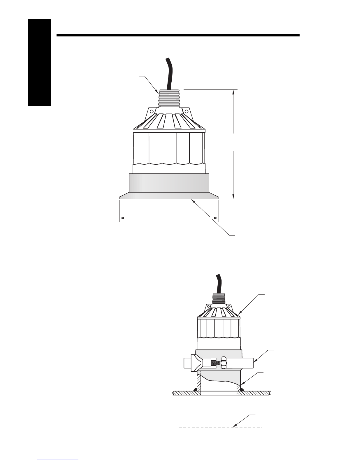
Outline and Dimensions
”
English
1” BSP
or
1” NPT
122 mm
(4.8”)
119 mm
(4.68”)
Ferrule Considerations
The primary customer requirement is
a 4" sanitary ferrule welded to a short
standpipe on the top of the tank. The
inner standpipe wall and ends must
be smooth and free of burrs, ridges,
or seams, and
applicable regulations.
The standpipe extension between
the mating ferrule and the tank top
cannot be longer than the blanking
distance as determined by the
Siemens Milltronics transceiver. The
blanking distance is the minimum
possible measurement range listed in
Specifications
the
must comply with all
on page 3.
radiating PTFE face
XCT-8
transducer
sanitary
clamp
standpipe
topped with 4
ferrule
Do not over tighten the mounting.
Hand tightening of the mounting
hardware is sufficient.
Page EN-4 XCT-8 Sanitary Transducer– INSTRUCTION MANUAL 7ML19985HX62
blanking
distance
Page 7
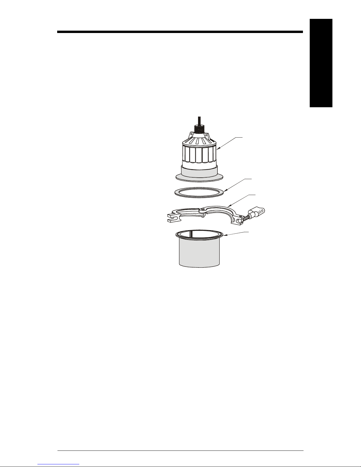
Mounting
Mount the transducer so that it is above the maximum material level by more than the
blanking value to ensure that accurate results are achieved. Refer to the associated
transceiver manual for information on setting the blanking value.
The transducer must be mounted so that the axis of transmission is perpendicular to the
measured surface to get the most reliable signal. See
for an example.
Always use an isolation gasket
(customer supplied) when
mounting the XCT-8. This gasket
reduces ultrasonic energy
coupling to the mounting
hardware.
Transducer must be mounted on a
4” ferrule. Do not mount by conduit
threads.
After applying the sanitary clamp,
adjust the clamp as required to
seal the transducer to the vessel
ferrule. Do not over tighten the
mounting. Hand tightening of the
mounting hardware is sufficient.
Transducer Placement
XCT - 8 transducer
isolating gasket
(customer
supplied)
sanitary clamp
4” sanitary ferrule
on page 7
English
• sanitary clamp – Siemens
Milltronics 7ML1830-1BR
May be substituted with a
clamp meeting these
specifications:
• 4” single hinge, sanitary clamp
• 4.820” interior diameter
•300 psi rated
• sanitary ferrule – customer supplied
Refer to the associated transceiver manual for details on blanking, standpipe length, and
wiring.
7ML19985HX62 XCT-8 Sanitary Transducer– INSTRUCTION MANUAL Page EN-5
Page 8
Interconnection
Notes:
• Installation shall only be performed by qualified personnel and in accordance
English
Cable Extension
with local governing regulations.
• Do not route cable openly. Run cable separately in a grounded metal conduit
to protect it from ambient electrical noise.
• Use the supplied shielded, 3-wire cable to connect the transducer to the
Siemens Milltronics transceiver. Supplied cable lengths are 1 m (3 ft).
• Seal all thread connections to prevent the ingress of moisture.
• Do not run cable near high voltage or current runs, contacts, or SCR control
drives.
• The terminal blocks on the transceiver are described in the transceiver
manual.
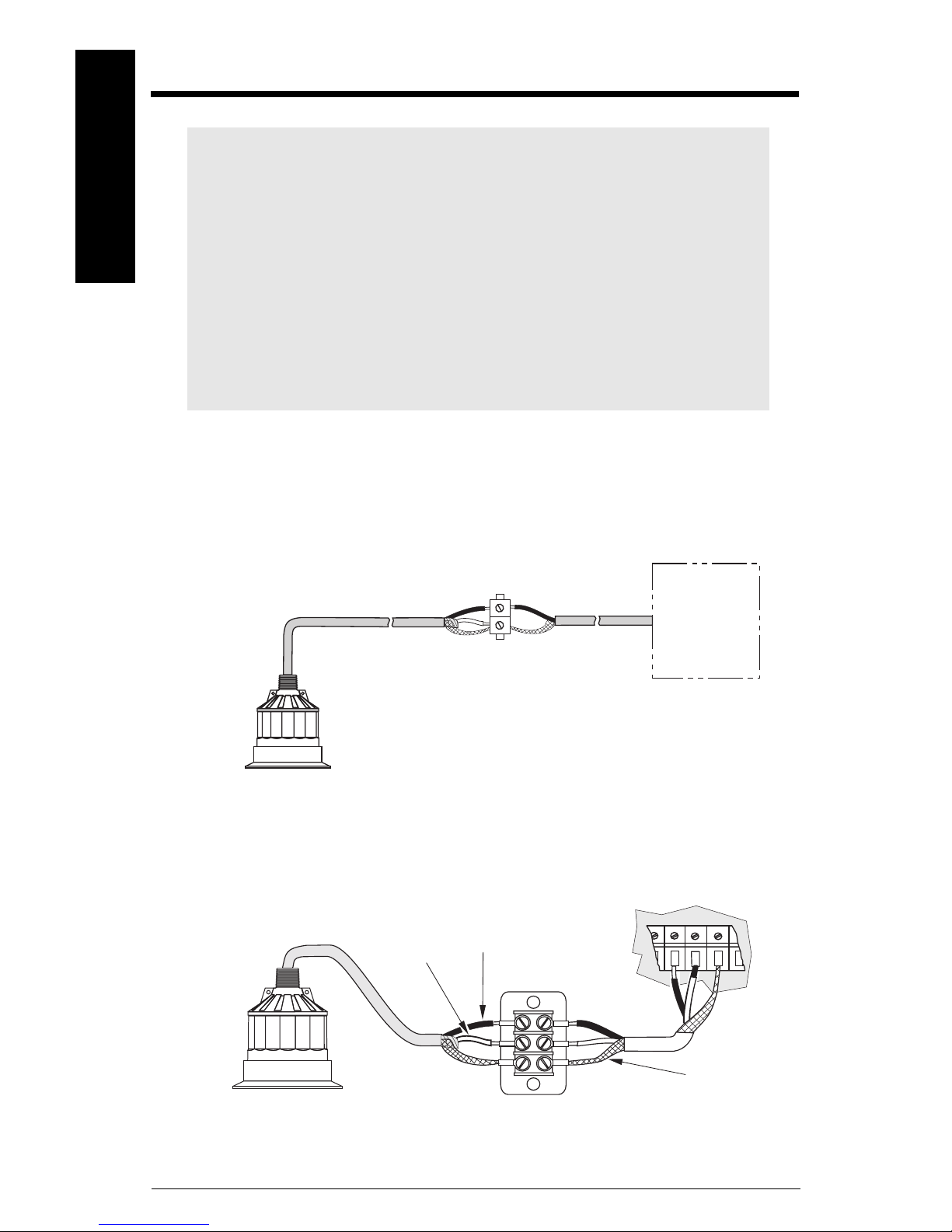
Applies to the MiniRanger Plus and SITRANS LU/AiRanger series of transceivers.
Connect the supplied cable to a junction box and use RG–62 A/U coaxial cable from there
to the transceiver. This setup is effective for combined runs up to 365 m (1200 ft).
Siemens
Milltronics
transceiver
junction box
Twisted Pair Extension
Applies to the MultiRanger 100/200 transceiver. Extend the cable using 18 AWG shielded /
twisted pair.
black
white
Page EN-6 XCT-8 Sanitary Transducer– INSTRUCTION MANUAL 7ML19985HX62
drain / shield
junction box
Page 9
Application
A
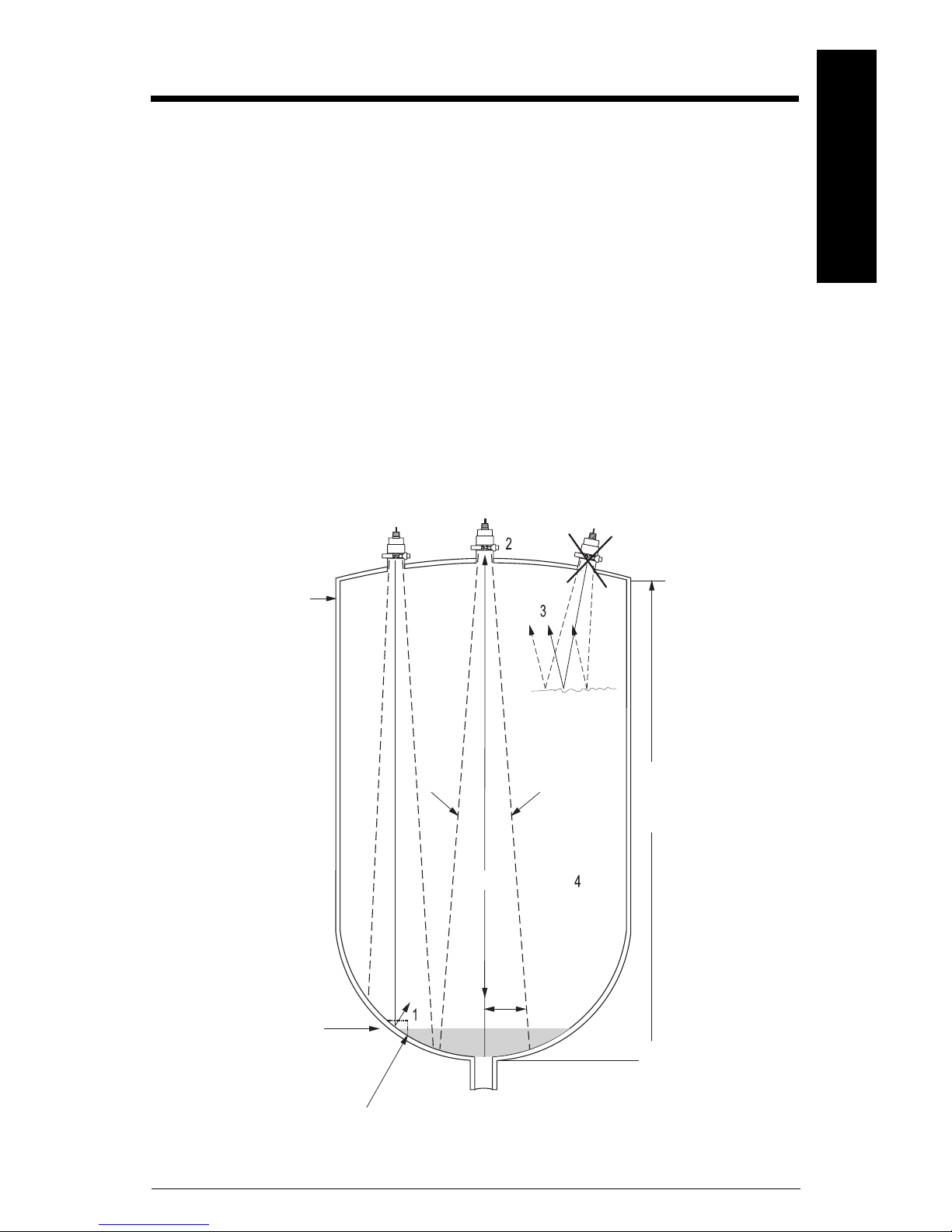
Transducer Placement
Locations (See diagram below for reference)
A: Primary location
The preferred location and to be used when possible. The center of the tank generally
gives the most reliable readings as there are fewer obstructions, minimizing false echoes.
B: Alternate location
The alternate location and used if the centre of the tank is already in use or if the tank
roof cannot hold the transducer safely.
C: Poor location
The avoided location. The echoes will reflect away from the transducer face.
English
maintain full fluid
level for full or
offset calibration.
Do not allow
.
material to enter
the blanking zone.
B
C
beam angle
span: distance between
Empty and Full levels in
measurement process.
empty level for B
location. Below this
level the echo reflects
away from the
transducer.
may require target to
obtain empty reading.
7ML19985HX62 XCT-8 Sanitary Transducer– INSTRUCTION MANUAL Page EN-7
run
tank manufacturer’s
empty level.
discharge
Page 10

Placement Notes
Please refer to the tank diagram on the previous page to locate the reference numbers
cited below.
1. Beam should not detect bin bottom.
English
If this occurs use range extension parameters (on transceivers where available) to omit
false echoes. The XCT- 8 transducer operates with a beam angle of 12° and has a rise to
run ratio of approximately 10:1. This means that for every 1m (3.3 ft.) of tank height you
must allow for 0.1m (0.3 ft.) of material surface to reflect the ultrasonic pulses. In most
tanks the transducer should be centered as much as possible (without interference from
inlet) for optimum reading range.
2. Sound beam must be perpendicular to liquid surface.
When mounting the standpipe and ferrule you must ensure that the transducer face is
parallel with the liquid surface.
3. Echo has missed an improperly leveled transducer.
Similar to Note 2, ensure that the standpipe and ferrule are mounted so that the
transducer is face level with the measured liquid.
4. Calibrate under normal conditions.
When performing an empty or full calibration, the tank must contain its normal vapour
and be at its normal temperature.
Notes:
• The transducer is to be used only in the manner outlined in this instruction
manual.
• This transducer is recommended for use with liquids only.
Process Temperature Variations
The PTFE facing is constructed to allow for intense "clean-in-place" applications. When
installing the XCT-8 transducer into a system that uses a high temperature "clean-inplace" process you must account for temperature variations in the transducer.
The temperature sensor’s time constant is 45 minutes. This means that it takes 45 minutes
to change 63.2% of the temperature difference between the transducer and ambient.
Consult your engineering handbook for details on temperature constants.
Page EN-8 XCT-8 Sanitary Transducer– INSTRUCTION MANUAL 7ML19985HX62
Page 11
Einleitung
Dieses Produkt ist vorgesehen zum Gebrauch in Industrieumgebungen. Bei Verwendung in Wohngebieten kann es zu Störungen von
verschiedenen Funkanwendungen kommen.
Die Ultraschallsensoren Baureihe Echomax XCT-8
werden zusammen mit Siemens Milltronics Ultra-
schall-Füllstandmessumformern betrieben.
Der Sensor wandelt die elektrische Energie des
Sendeimpulses vom Messumformer in akustische
Energie um. Die akustische Energie des Echos wird
dann wieder in elektrische Energie für den Messumformer zurückgewandelt. Zur Auswertung des
Signals verwendet der Siemens Milltronics Messumformer die von Siemens Milltronics entwickelte,
patentierte Sonic Intelligence®. Die Leistung des
Ultraschallimpulses nimmt am 12° Schallkegel von
der Sendefläche um –3 dB ab. Innerhalb dieses
Kegels dürfen sich keine Gegenstände befinden,
die als Störechos ausgewertet werden könnten.
Ultraschallsensor
Deutsch
Sensor-
sendefläche
-3db Grenzlinie
Die XCT-8 Sensoren sind mit einem integrierten
Temperaturfühler ausgestattet. Dieser meldet dem
Messumformer die Temperatur am Ultraschallsensor. Der Anschluss ist eindeutig, sowohl Ultraschallals auch Temperaturkomponenten des Sensors verwenden dieselben Adern in der Leitung. Dies
ermöglicht dem Siemens Milltronics Messumformer eine automatische Kompensation der Schallgeschwindigkeitskonstante bei Temperaturschwankungen.
Die Sensorsendefläche aus PTFE ermöglicht den Einsatz des Sensors in Applikationen mit
Reinigungszyklen der Lebensmittelindustrie.
Übertragungsachse, senkrecht zur
Sensorsendefläche
Messumformer
Die XCT-8 Sanitärsensoren sind mit folgenden Messumformern kompatibel:
• MiniRanger Plus
• MultiRanger 100/200
•HydroRanger 200
• SITRANS LU 01
• SITRANS LU 02
• SITRANS LU 10
•AiRanger SPL
•AiRanger DPL
•AiRanger XPL
7ML19985HX62 XCT-8 Sanitärsensor– BETRIEBSANLEITUNG Seite DE-1
Page 12

Allgemeine Richtlinien
WARNUNG: Die Werkstoffe werden entsprechend ihrer chemischen
Beständigkeit (oder Trägheit) für allgemeine Zwecke gewählt. Bei Einsatz
in besonderen Umgebungen prüfen Sie vor Installation die chemische
Beständigkeit anhand einschlägiger Tabellen.
Hinweis: PVDF und PTFE sind unter den beschriebenen Einsatzbedingungen
gegen die meisten Chemikalien beständig. Vor der Installation des XCT-8
Sensors sollten Sie jedoch, bei Einsatz in besonderen Umgebungen, zunächst
die chemische Beständigkeit anhand einschlägiger Tabellen prüfen.
Wartung
Deutsch
Der XCT-8 erfordert keine besondere Wartung oder Reinigung.
Gerätereparatur und Haftungsausschluss
Alle Änderungen und Reparaturen müssen von qualifiziertem Personal unter Beachtung
der jeweiligen Sicherheitsbestimmungen vorgenommen werden. Bitte beachten Sie:
• Der Anwender ist für alle vom Anwender oder seinem Bevollmächtigten
durchgeführten Änderungen und Reparaturen am Gerät verantwortlich.
• Alle neuen Bauteile sind von Siemens Milltronics Process Instruments Inc. bereit zu
stellen.
• Reparieren Sie lediglich defekte Bauteile.
• Defekte Bauteile dürfen nicht wiederverwendet werden.
Seite DE-2 XCT-8 Sanitärsensor– BETRIEBSANLEITUNG 7ML19985HX62
Page 13

Technische Daten
Messbereich
• 0,6 m (2 ft) bis 8,0 m (26 ft). Applikationsabhängig.
Temperaturbereich
• – 40 bis 125 °C (–40 bis 260 °F) bei 0,6 m (2 ft)
Schallkegel
•12°
Frequenz
•44 KHz
Umgebungsbedingungen
• Montage: innen / im Freien
• Umgebungstemperatur: –40 bis 125 °C (–40 bis 260 °F)
• Höhe max. 2000 m
• Verschmutzungsgrad 4
Deutsch
Druck
• 200 kPa (29 psi)
Temperaturfühler
• Integriert
Gehäuse
• PVDF mit Sensorsendefläche aus PTFE
• PTFE Flansch / Gegenflansch
Montage
• Sockel: 4" Clamp-Anschluss
• Leitung: 1" NPT Gewinde oder 1" BSP
Kabel
• 2-adrig verdrilltes Paar/Litze, geschirmt, 0,55 mm2 (20 AWG) PVC-Mantel
• Max. Kabellänge: 365 m (1200 ft)
Zulassungen
•CE •CSA
7ML19985HX62 XCT-8 Sanitärsensor– BETRIEBSANLEITUNG Seite DE-3
•C-TICK
US/C
Page 14

Maßbilder
Deutsch
1” BSP
oder
1” NPT
122 mm
(4,8”)
Gegenflansch
Kundenanforderung ist ein 4" SanitärGegenflansch, der an ein kurzes
Standrohr oben auf dem Behälter
angeschweißt wird. Die Innenseite
des Standrohrs muss glatt sein (ohne
Schweiß-, Gussnähte oder sonstige
Verstrebungen) und allen gültigen
Richtlinien entsprechen.
Die Höhe des Standrohrs vom
Gegenflansch bis zur Behälterdecke
darf die im Siemens Milltronics Messumformer bestimmte Nahbereichsausblendung nicht überschreiten. Die
Nahbereichsausblendung entspricht
dem minimalen Abstand zum zu messenden Material; siehe
auf Seite 3.
Daten
Bei der Montage (mit Conduit) nicht
zu stark anziehen. Handfest ist ausreichend.
Technische
119 mm
(4,68”)
Sensorsendefläche
aus PTFE
XCT-8 Sensor
SanitärClamp
Standrohr
mit 4" Gegenflansch
Ausblendungsabstand
Seite DE-4 XCT-8 Sanitärsensor– BETRIEBSANLEITUNG 7ML19985HX62
Page 15

Montage
Um präzise Messwerte zu erhalten, beachten Sie bei der Sensormontage einen Mindestabstand zum maximalen Materialfüllstand entsprechend der Nahbereichsausblendung.
Angaben zur Einstellung der Ausblendung finden Sie in der zugehörigen Betriebsanleitung
des Messumformers.
Für eine maximale Signalzuverlässigkeit ist der Sensor so anzubringen, dass die Übertragungsachse senkrecht zur Flüssigkeitsoberfläche steht. Ein Beispiel finden Sie unter
des Sensors
Für die Montage des XCT-8 ist
immer eine Isolierdichtung (vom
Kunden geliefert) zu verwenden.
Diese Dichtung stellt eine optimale
Anpassung des Sensors an den
Montageflansch sicher und
gewährleistet genaue Messergebnisse.
Die Sensormontage muss auf
einem 4" Gegenflansch erfolgen.
Der Sensor darf nicht über Einschraubgewinde montiert werden.
auf Seite 8.
XCT-8 Sensor
Isolierdichtung
(kundenseitig)
Sanitär-Clamp
Einbau
Deutsch
Bringen Sie den Sanitär-Clamp an
und stellen Sie ihn nach Bedarf ein,
bis der Sensor hermetisch dicht am
Gegenflansch befestigt ist. Bei der
Montage nicht zu stark anziehen.
Handfest ist ausreichend.
• Sanitär-Clamp – Siemens
Milltronics 7ML1830-1BR
Kann durch ein Clamp mit folgenden Eigenschaften ersetzt werden:
• 4" Sanitär-Clamp mit Einzelscharnier
• Innendurchmesser 4,820”
• Nenndruck 300 psi
• Sanitär-Gegenflansch – kundenseitig
Genaue Angaben zu Ausblendung, Standrohrlänge und Anschluss finden Sie in der
Betriebsanleitung des verwendeten Messumformers.
Sanitär-Gegenflansch 4”
7ML19985HX62 XCT-8 Sanitärsensor– BETRIEBSANLEITUNG Seite DE-5
Page 16

Anschluss
Hinweise:
• Die Installation darf nur durch qualifiziertes Personal und unter Beachtung
der örtlichen, gesetzlichen Bestimmungen durchgeführt werden.
• Die Kabel sollten nicht offen verlegt werden. Zur optimalen Störsicherheit
sind die Kabel getrennt in einem geerdeten Metallrohr zu verlegen.
• Zum Anschluss des Sensors an den Siemens Milltronics Messumformer
verwenden Sie das mitgelieferte, geschirmte 3-adrige Kabel. Das Kabel wird
in einer Länge von 1 m (3 ft) geliefert.
• Alle Gewindeanschlüsse sind so abzudichten, dass das Eindringen von
Feuchtigkeit verhindert wird.
• Vermeiden Sie eine Leitungsführung in der Nähe von Hochspannungs-,
Motorleitungen, Schaltschützen oder Frequenzumrichtern (SCR
Steuerantriebe).
Deutsch
Kabelverlängerung
• Eine Beschreibung der Klemmblöcke des Messumformers finden Sie in der
Betriebsanleitung des Messumformers.
Bezieht sich auf die Messumformer der Baureihe MiniRanger Plus und SITRANS LU/AiRanger. Schließen Sie das mitgelieferte Kabel an einen Anschlusskasten an und verwenden Sie
von da ab ein RG-62 A/U Koaxialkabel bis zum Messumformer. Diese Anordnung gilt für
eine Gesamtlänge von 365 m (1200 ft).
Siemens
Milltronics
Messumformer
Anschlusskasten
Seite DE-6 XCT-8 Sanitärsensor– BETRIEBSANLEITUNG 7ML19985HX62
Page 17

Verlängerung mit verdrillter Leitung
Bezieht sich auf den Messumformer MultiRanger 100/200. Kabelverlängerung unter Verwendung von geschirmtem Kabel mit verdrilltem Aderpaar, 18 AWG.
Anschlusskasten
schwarz
weiß
Schirm
Anschlusskasten
Deutsch
7ML19985HX62 XCT-8 Sanitärsensor– BETRIEBSANLEITUNG Seite DE-7
Page 18

Applikation
A
Einbau des Sensors
Einbaustellen (Siehe Zeichnung unten)
A. Bevorzugte Einbaustelle
Der Sensor sollte nach Möglichkeit an dieser Stelle montiert werden. Die Behältermitte
ergibt die zuverlässigsten Messwerte, da weniger Einbauten vorhanden sind, durch die
Störechos entstehen könnten.
B: Ausweichlösung
Diese Einbaustelle ist geeignet, wenn die Behältermitte nicht frei ist oder die Tankdecke zu
Deutsch
schwach ist, um den Sensor sicher zu montieren.
C: Schlechte Einbaustelle
Vermeiden Sie diese Einbaustelle, da die Echos verspiegelt werden.
Für eine Voll- oder
Nullpunktkalibrierung den Füllstand
auf 100% halten.
.
Das Material darf
nicht in den Ausblendungsbereich
gelangen.
B
C
Schallkegel
Messbereich: Abstand
zwischen Min. und Max.
Füllstand im Prozess.
Nullpunkt für die Ausweichlösung B.
Unterhalb dieses Füllstands kann sich das
Echo vom Sensor verspiegeln.
Reflektorplatte kann notwendig
sein, um Nullpunkt stabil zu halten.
Seite DE-8 XCT-8 Sanitärsensor– BETRIEBSANLEITUNG 7ML19985HX62
Radius
Nullpunkt des
Behälters laut
Herstellerangabe.
Austrag
Page 19

Anmerkungen zu den Einbaustellen
Die Nummern im Folgenden beziehen sich auf die Zeichnung der vorigen Seite.
1. Der Behälterboden sollte nach Möglichkeit nicht erfasst werden.
Falls der Behälterboden erfasst wird, sind die Störechos mittels der Parameter zur
Endbereichserweiterung (bei Messumformern mit entsprechender Funktion)
auszublenden. Der Schallkegel des XCT-8 Sensors beträgt 12°, mit einem Verhältnis
Anstieg:Radius von ca. 10:1. Das bedeutet, dass für 1 m (3,3 ft) Behälterhöhe mit einer
Materialoberfläche von 0,1 m (0,3 ft) für die Reflexion der Ultraschallimpulse gerechnet
werden muss. In den meisten Tanks wird der optimale Messwert durch eine mittige
Montage (ohne Störung durch die Befüllung) erreicht.
2. Die Schallkeule muss senkrecht zum Flüssigkeitsspiegel sein.
Bei einer Montage mit Standrohr und Gegenflansch muss darauf geachtet werden, dass
die Sensorsendefläche parallel zur Flüssigkeitsoberfläche steht.
3. Echoverspiegelung aufgrund eines falschen Sensoreinbaus.
Wie unter Punkt 2 muss auch hier darauf geachtet werden, dass die Sensorsendefläche
parallel zur Flüssigkeitsoberfläche ist.
4. Kalibrierung unter normalen Betriebsbedingungen.
Bei einer Kalibrierung des Null- oder Vollpunkts muss der Behälter unter normalen
Bedingungen (Dampf, Temperatur, ...) betrieben werden.
Hinweise:
• Der Sensor darf nur gemäß den Anweisungen in dieser Betriebsanleitung
verwendet werden.
• Dieser Ultraschallsensor sollte nur zur Messung von Flüssigkeiten eingesetzt
werden.
Temperaturschwankungen im Prozess
Deutsch
Die Sensorsendefläche aus PTFE ist für den Einsatz in Applikationen mit Reinigungszyklen
geeignet. Wird der XCT-8 Sensor in einem System mit Reinigungsprozess bei Hochtemperaturen eingesetzt, so müssen die Temperaturschwankungen im Sensor berücksichtigt werden.
Die Zeitkonstante des Temperaturfühlers beträgt 45 Minuten. Demnach dauert es 45 Minuten, bis 63,2% der Temperaturdifferenz zwischen Sensor und Umgebung kompensiert werden. Angaben zu Temperaturkonstanten finden Sie in Ihrem Handbuch der
Verfahrenstechnik.
7ML19985HX62 XCT-8 Sanitärsensor– BETRIEBSANLEITUNG Seite DE-9
Page 20

Deutsch
Seite DE-10 XCT-8 Sanitärsensor– BETRIEBSANLEITUNG 7ML19985HX62
Page 21

Introducción
Este aparato se ha diseñado para el uso en ámbito industrial. El uso
de este aparato en instalaciones residenciales puede causar
interferencias a las comunicaciones por radio.
El transductor ultrasónico Echomax XCT-8 se
utiliza con los transmisores de nivel Siemens
Milltronics.
El sensor convierte la energía eléctrica de la
pulsación emitida por el transmisor en energía
acústica, y convierte la energía acústica del eco
de retorno en energía eléctrica. El transmisorreceptor Siemens Milltronics interpreta esta señal
mediante los algoritmos patentados Sonic
TM
Intelligence
acústica se reduce (– 3 dB) en un cono de 12° de
la superficie emisora del sensor. Mantener este
cono de emisión libre de obstrucciones para
limitar el registro de falsos ecos.
de Siemens Milltronics. La potencia
sensor
ultrasónico
superficie
emisora (cara)
límite -3dB
El sensor XCT-8 incorpora un sensor de
temperatura que informa al transmisor de la
temperatura ambiente. Se trata de una conexión
transparente ya que los componentes
relacionados con el ultrasonido y con la variable
temperatura utilizan los mismos conductores. Ello
garantiza asimismo la compensación y el ajuste
automático de la velocidad del sonido con el
transmisor Siemens Milltronics cuando se presentan variaciones de temperatura.
El sensor dispone de una superficie emisora de PTFE para aplicaciones con alimentos y
ciclos intensivos de limpieza.
eje de
transmisión,
irradiado
axialmente de la
cara del sensor
Transmisores
El sensor sanitario XCT-8 es funcionalmente compatible con:
• MiniRanger Plus
• MultiRanger 100/200
•HydroRanger 200
• SITRANS LU 01
• SITRANS LU 02
• SITRANS LU 10
•AiRanger SPL
•AiRanger DPL
•AiRanger XPL
Español
7ML19985HX62 Sensor sanitario XCT-8– INSTRUCCIONES DE SERVICIO Página ES-1
Page 22

Indicaciones generales
ADVERTENCIA: Los materiales de construcción son seleccionados en
base a su compatibilidad química (o inertidad) para usos generales.
Antes de instalar los sensores en ambientes específicos recomendamos
consulte las tablas de compatibilidad química.
Nota: Los materiales PVDF y PTFE son inmunes a la mayoría de substancias
químicas, en condiciones nominales de funcionamiento. Antes de instalar el
sensor XCT-8 en ambientes específicos recomendamos consulte las tablas de
compatibilidad química.
Mantenimiento
El sensor XCT-8 no necesita mantenimiento o limpieza.
Reparaciones y límite de responsabilidad
Sólo el personal calificado está autorizado a intervenir en este equipo. Las
modificaciones y reparaciones deberán efectuarse respetando los códigos de práctica
aplicables. Nota importante:
Español
• El usuario es el único responsable de las modificaciones y reparaciones en el
dispositivo efectuadas por él mismo o por su agente.
• Recomendamos utilizar sólo recambios originales Siemens Milltronics Process
Instruments Inc.
• Reparar sólo los componentes defectuosos.
• No reutilizar los componentes defectuosos.
Página ES-2 Sensor sanitario XCT-8– INSTRUCCIONES DE SERVICIO 7ML19985HX62
Page 23

Especificaciones técnicas
Rango de medida
• 0,6 m (2 ft) - 8,0 m (26 ft), según la aplicación.
Rango de temperatura
• – 40 a 125 °C (–40 a 260 °F) a 0,6 m (2 ft)
Ángulo de haz
•12°
Frecuencia
•44 KHz
Condiciones ambientales
• Ubicación: montaje interior/a prueba de intemperie
• Temperatura ambiente: – 40 a 125 °C (–40 a 260 °F)
• Máxima altitud 2000 m
• Grado de contaminación 4
Presión
Español
• 200 kPa (29 psi)
Sensor de temperatura
• Incorporado
Caja
• PVDF con superficie emisora de PTFE
• Brida/férula PTFE
Montaje
• Base: abrazadera sanitaria 4”
• Conducto: rosca 1” NPT o 1” BSP
Cable
• 2 conductores trenzado apantallado con blindaje, 0.55 mm2 (20 AWG), cubierta de PVC
• Máxima separación: 365 m (1200 ft)
Certificaciones
•CE •CSA
7ML19985HX62 Sensor sanitario XCT-8– INSTRUCCIONES DE SERVICIO Página ES-3
NRTL/C
•C-TICK
Page 24

Esquema de dimensiones
1" BSP
o bien
1" NPT
122 mm
(4,8”)
Español
Férula
119 mm
(4,68")
Muchos usuarios solicitan una férula
sanitaria de 4", soldada en un tubo
vertical corto, en la parte superior del
depósito. Es imprescindible
comprobar la ausencia de costuras y
puntos de soldeo en la superficie
interior del tubo vertical. La
instalación deberá cumplir con los
requisitos aplicables.
La instalación no deberá tener una
extensión (férula/parte superior del
depósito) superior a la zona muerta
definida por el transmisor-receptor
Siemens Milltronics. La zona muerta
corresponde al rango de medida
mínimo indicado en las
Especificaciones
, página 3.
superficie emisora de
PTFE
sensor XCT-8
abrazadera
sanitaria
tubo vertical
férula 4”
zona muerta
No apretar excesivamente durante el
montaje. Apretar el material
manualmente.
Página ES-4 Sensor sanitario XCT-8– INSTRUCCIONES DE SERVICIO 7ML19985HX62
Page 25

Montaje
Para máxima fiabilidad instalar el sensor a una distancia por lo menos equivalente a la
zona muerta, por encima del nivel más alto de material. El usuario encontrará más
información sobre el ajuste de la zona muerta en el manual de instrucciones del
transmisor de nivel.
Para maximizar la fiabilidad de las señales, instalar el sensor para que el eje de
transmisión sea perpendicular a la superficie del material. Ver la sección
sensor
, página 7.
Es imprescindible montar el XCT-8
con una junta de estanqueidad
(proporcionada por el cliente). Esta
junta permite optimizar el montaje
y la transmisión de la energía
ultrasónica.
Instalar el sensor ultrasónico en
una ferula de 4”. No instalar el
sensor por medio de las roscas.
sensor XCT-8
Colocación del
junta de
estanqueidad
(proporcionada
por el cliente)
Una vez colocada la abrazadera
sanitaria, efectuar los ajustes
necesarios para garantizar el sello
sensor/férula (depósito). No
apretar excesivamente durante el
montaje.
Apretar el material manualmente.
• Abrazadera sanitaria –
Siemens Milltronics
7ML1830-1BR
Se puede sustituir por una abrazadera que cumpla con las siguientes
especificaciones:
• abrazadera sanitaria 4” de articulación sencilla
• diámetro interior 4,820”
•300 psi
• Férula sanitaria – proporcionada por el cliente
Para más detalles sobre la zona muerta, la longitud del tubo vertical y el cableado ver el
manual de operación del transmisor.
abrazadera
sanitaria
férula sanitaria 4”
Español
7ML19985HX62 Sensor sanitario XCT-8– INSTRUCCIONES DE SERVICIO Página ES-5
Page 26

Interconexiones
Notas:
• Sólo el personal calificado está autorizado a intervenir en este equipo para la
instalación. Observar las indicaciones y los procedimientos de seguridad.
• Instalar protecciones adecuadas para los cables. Instalar los cables
separadamente en tuberías metálicas conectadas a tierra, para tener mayor
inmunidad al ruido ambiental.
• Se recomienda utilizar el cable proporcionado (1 m (3 ft) cable de 3
conductores blindado) para conectar el sensor al transmisor Siemens
Milltronics.
• Sellar todas las conexiones herméticamente para evitar infiltración y
humedad.
• Evitar la instalación del cable cerca de fuentes de alta tensión o alta
intensidad, contactores y sistemas de control, SCR.
• Los bloques de terminales del transmisor-receptor están descritos en el
manual de operación.
Extensión de cable
Para conectar el sensor y los transmisores MiniRanger Plus o AiRanger. Conectar el
cable proporcionado a una caja de conexión. Utilizar un cable coaxial RG–62 A/U para
conectar la caja de conexión y el transmisor. Con este tipo de instalación se admiten
separaciones de hasta 365 m (1200 ft).
Español
caja de conexión
Extensión con cable de par trenzado
Sólo para el transmisor MultiRanger 100/200. Para extensiones de cables, utilizar cable
de par trenzado/apantallado 18 AWG
negro
blanco
transmisor-receptor
Siemens Milltronics
Página ES-6 Sensor sanitario XCT-8– INSTRUCCIONES DE SERVICIO 7ML19985HX62
drenaje/blindaje
caja de conexión
Page 27

Aplicación
A
Ubicación del sensor ultrasónico
Emplazamientos (para más detalles véase la descripción a continuación)
A: Emplazamiento preferido
Emplazamiento recomendado para todas las aplicaciones. La ausencia de obstrucciones
en la parte central del depósito minimiza los falsos ecos y optimiza la fiabilidad de las
medidas.
B: Emplazamiento alternativo
Emplazamiento elegido si el sensor no se puede instalar en la parte central del depósito,
o cuando el techo del depósito no está diseñado para soportar el peso del sensor.
C: Emplazamiento inadecuado
Ubicación inapropiada del sensor. Refleja los ecos lejos de la superficie emisora del
sensor ultrasónico.
la calibración del nivel
proceso lleno o del
desfase precisa
mantener el máximo
.
nivel de líquido en el
depósito. Para ello es
imprescindible no
penetrar la zona
muerta.
B
C
ángulo de
haz
Español
span: distancia entre el
nivel proceso vacío y el
nivel proceso lleno.
nivel proceso vacío para
el emplazamiento B. El
eco se refleja lejos de la
superficie emisora del
sensor por debajo de
este nivel.
puede ser necesario definir
el blanco para medir el nivel
proceso vacío.
7ML19985HX62 Sensor sanitario XCT-8– INSTRUCCIONES DE SERVICIO Página ES-7
run
valor proceso vacío
definido por el
fabricante del depósito.
descarga
Page 28

Notas acerca del emplazamiento
Para más detalles sobre los números de referencia indicados a continuación véase por
favor el diagrama del depósito en la página precedente.
1. Es imprescindible evitar la detección del fondo del depósito.
De no ser posible, utilizar los parámetros de extensión del rango (disponibles en ciertos
transmisores) para no tomar en cuenta los falsos ecos. El sensor XCT- 8 funciona
produciendo un haz de emisión de 12° y una relación flecha/recorrido de 10:1
aproximadamente. Asimismo para obtener la reflexión de los pulsos deberá garantizarse
0,1 m (0,3 ft.) de material por cada metro (3,3 ft.) de altura del depósito. En muchos casos
para garantizar el correcto funcionamiento habrá que comprobar que el sensor esté bien
centrado respecto al depósito (sin interferencias tipo entrada de material).
2. Montar el sensor para que el eje de transmisión sea perpendicular a la
superficie del líquido.
Durante el montaje del tubo vertical y de la férula, asegurarse de que la superficie
emisora del sensor esté paralela a la superficie del líquido.
3. El montaje incorrecto del sensor impide la recepción del eco.
Similar a la Nota 2: durante el montaje del tubo vertical y de la férula comprobar que la
cara del sensor sea paralela a la superficie del líquido.
4. Efectuar la calibración en condiciones de funcionamiento normales.
Realizar la calibración del nivel proceso lleno o vacío en condiciones de funcionamiento
Español
normales: comprobar la concentración de vapor y la temperatura en el depósito.
Notas:
• Es imprescindible seguir las instrucciones proporcionadas en este manual.
• Este sensor está diseñado para su uso en aplicaciones con líquidos.
Variaciones de la temperatura de proceso
La superficie emisora de PTFE está diseñada especialmente para aplicaciones con ciclos
intensivos de limpieza. La instalación del sensor XCT-8 en aplicaciones que combinen
ciclos intensivos de limpieza con altas temperaturas requiere tomar en consideración las
variaciones de temperatura presentes en el sensor.
El sensor de temperatura está diseñado con una constante de tiempo de 45 minutos.
Asimismo se necesitan 45 minutos para compensar 63,2% de la diferencia observada
entre la temperatura del sensor y la temperatura ambiente. Para más detalles sobre las
constantes (temperatura) consulte las reglas de ingeniería.
Página ES-8 Sensor sanitario XCT-8– INSTRUCCIONES DE SERVICIO 7ML19985HX62
Page 29

Introduction
Cet instrument est conçu pour une utilisation en milieu industriel.
Utilisé en zone résidentielle, cet appareil peut provoquer des
perturbations des communications radio.
Le transducteur Echomax XCT-8 est relié aux
contrôleurs de niveau ultrasoniques Siemens
Milltronics.
Le transducteur convertit l'énergie électrique de
l'impulsion transmise et reçue du transmetteur, en
énergie acoustique. L'énergie acoustique de
l'écho est ensuite convertie en énergie électrique.
Le transmetteur Siemens Milltronics met en
oeuvre les algorithmes brevetés Sonic
Intelligence®de Siemens Milltronics pour le
traitement du signal. La puissance de l'impulsion
ultrasonique est réduite de – 3 dB dans un cône
de 12° de la face émettrice du transducteur.
Garder cette zone libre de toute obstruction pour
éviter de détecter des échos parasites.
Le transducteur XCT-8 est équipé d'un capteur
conçu pour mesurer la température ambiante et la
transmettre au transmetteur de niveau. Cette
connexion est transparente : les éléments relatifs
à l'ultrason et à la température utilisent les
mêmes fils de sortie. On obtient ainsi une
compensation automatique de la vitesse du son
avec le transmetteur Siemens Milltronics, indépendamment des variations de
température.
Ce transducteur comporte une face émettrice en PTFE adaptée à l'industrie alimentaire
et aux applications comportant des cycles de nettoyage intensifs.
transducteur
face émettrice
du transducteur
limite -3dB
axe de
transmission
perpendiculaire
à la face
émettrice
Français
Transmetteurs de niveau
Le transducteur sanitaire XCT-8 est compatible avec les transmetteurs suivants :
• MiniRanger Plus
• MultiRanger 100/200
•HydroRanger 200
• SITRANS LU 01
• SITRANS LU 02
7ML19985HX62Transducteur sanitaire XCT-8– INSTRUCTIONS DE SERVICE Page FR-1
• SITRANS LU 10
•AiRanger SPL
•AiRanger DPL
•AiRanger XPL
Page 30

Consignes générales
AVERTISSEMENT : Ce système est conçu avec des matériaux choisis
en fonction de leur compatibilité chimique, pour une exploitation
générale. Se reporter aux tableaux de compatibilité avant toute
utilisation dans un environnement spécifique.
Note : En conditions de fonctionnement nominales, le PVDF et le PTFE résistent
à la plupart des substances chimiques. Veuillez consulter les tableaux de
compatibilité chimique avant toute installation du transducteur XCT-8 dans un
environnement spécifique.
Maintenance
Le transducteur XCT-8 ne requiert pas de maintenance ou de nettoyage particulier.
Réparation de l’unité et limite de responsabilité
Toute modification ou réparation doit être effectuée par un personnel qualifié.
Veuillez respecter les consignes de sécurité. Remarques importantes :
• Toute modification ou réparation du système effectuée par l'utilisateur ou par son
mandataire sera placée sous la responsabilité de l'utilisateur.
• Utiliser seulement des composants fournis par Siemens Milltronics Process
Instruments Inc.
• Réparer uniquement les composants défectueux.
• Les composants défectueux ne doivent pas être réutilisés.
Français
Page FR-2 Transducteur sanitaire XCT-8– INSTRUCTIONS DE SERVICE 7ML19985HX62
Page 31

Caractéristiques techniques
Plage de mesure
• 0,6 m (2 ft) à 8,0 m (26 ft) ; en fonction des conditions dans l'application.
Plage de température
• – 40 à 125 °C (–40 à 260 °F), à 0,6 m (2 ft)
Angle du faisceau
•12°
Fréquence
•44 KHz
Caractéristiques environnementales
• Montage : en intérieur / extérieur
• Température ambiante : – 40 à 125 °C (–40 à 260 °F)
• Altitude : 2000 m maximum
• Degré de pollution 4
Pression
• 200 kPa (29 psi)
Capteur de température
•Interne
Boîtier
• PVDF, face émettrice en PTFE
• Bride PTFE / collier
Montage
• Base : clamp sanitaire 4”
• Conduit : filetage 1” NPT ou 1” BSP
Câble
• 2 conducteurs paire torsadée/blindée, feuille métallique 0,55 mm2 (20 AWG), gaine PVC
• Longueur max. du câble : 365 m (1200 ft)
Français
Homologations
•CE •CSA
7ML19985HX62Transducteur sanitaire XCT-8– INSTRUCTIONS DE SERVICE Page FR-3
US/C
•C-TICK
Page 32

Encombrement
1” BSP
ou
1” NPT
122 mm
(4,8”)
119 mm
(4,68”)
Informations concernant le collier
Le transducteur est généralement
utilisé avec un collier sanitaire 4",
soudé sur un manchon court, situé
sur la partie supérieure du réservoir.
Les parois intérieures et les
extrémités du manchon doivent être
lisses, sans bavures, stries ou
soudures, et doivent répondre aux
dispositions applicables.
Français
La longueur du manchon situé entre
le collier et la partie supérieure du
réservoir ne doit pas être supérieure
à la zone morte définie pour le
transmetteur Siemens Milltronics.
La zone morte correspond à la valeur
minimale de la portée (plage de
mesure) indiquée dans les
Caractéristiques,
page 3.
face émettrice en PTFE
transducteur
XCT-8
clamp
sanitaire
manchon
équipé d'un
collier 4”
zone morte
Eviter un serrage excessif. Le
serrage manuel du matériel est
généralement suffisant.
Page FR-4 Transducteur sanitaire XCT-8– INSTRUCTIONS DE SERVICE 7ML19985HX62
Page 33

Montage
Pour obtenir des mesures fiables, installer le transducteur au dessus du niveau maximum
du matériau, à une distance supérieure à la zone morte. Pour plus de détails sur le
réglage de la zone morte se reporter au manuel d'utilisation du transmetteur associé au
transducteur.
Pour optimiser la fiabilité du signal, installer le transducteur de sorte que l'axe de
transmission soit perpendiculaire à la surface mesurée. Pour plus de détails se reporter à
la section
Il est impératif de toujours utiliser
le transducteur XCT-8 avec un joint
d'isolation (fourni par le client). Ce
joint optimise le montage
transducteur/piquage et la
transmission des signaux
ultrasoniques.
Installer le transducteur sur un
collier 4”. Ne pas fixer le
transducteur avec le filetage
conduit.
Positionnement du transducteur,
page 7.
transducteur XCT-8
joint d'isolation
(fourni par le client)
clamp sanitaire
Installer le clamp sanitaire et
l'ajuster tel que nécessaire pour
garantir le montage étanche
transducteur/réservoir (collier).
Eviter un serrage excessif. Le
serrage manuel du matériel est
généralement suffisant.
• Clamp sanitaire – Siemens Milltronics 7ML1830-1BR
Peut être substitué avec un clamp avec les caractéristiques suivantes :
• clamp sanitaire 4” à charnière simple
• diamètre intérieur 4,820”
•300 psi
• Joint sanitaire – fourni par le client.
Pour plus de détails sur la zone morte, la longueur de la rehausse et le câblage, se
reporter au manuel d'utilisation du transmetteur.
collier sanitaire 4”
Français
7ML19985HX62Transducteur sanitaire XCT-8– INSTRUCTIONS DE SERVICE Page FR-5
Page 34

Interconnexions
Notes :
• L'installation doit être effectuée par un personnel qualifié, en accord avec les
dispositions locales en vigueur.
• Le cheminement du câble doit être effectué avec des protections adaptées.
Installer le câble sous conduit métallique mis à la terre, sans aucun autre
câble, et le protéger des bruits électriques ambiants.
• Connecter le transducteur au transmetteur Siemens Milltronics avec le câble
3 conducteurs blindé fourni. L'unité est livrée avec 1 m de câble (3 ft).
• Assurer un serrage hermétique des connexions pour éviter toute humidité
d'infiltration.
• Eviter l'installation du câble près de sources haute tension ou haute
intensité, contacteurs et systèmes de commande à thyristors.
• Les borniers de connexion du transmetteur sont illustrés dans le manuel
d'utilisation associé.
Extension câble
Utilisable pour les transmetteurs MiniRanger Plus ainsi que la série de transmetteurs
AiRanger et SITRANS LU. Relier le câble fourni à la boîte de jonction puis utiliser un câble
coaxial RG–62 A/U pour la liaison boîte de jonction - transmetteur. Ce type d'installation
est conseillé pour les extensions de câble jusqu'à 365 m (1200 ft).
Extension paire torsadée
Français
Utilisable pour le transmetteur MultiRanger 100/200. Pour les extensions, utiliser un câble
paire blindée/torsadée (18 AWG)
blanc
transmetteur
Siemens
Milltronics
boîte de jonction
noir
Page FR-6 Transducteur sanitaire XCT-8– INSTRUCTIONS DE SERVICE 7ML19985HX62
drain/blindage
boîte de jonction
Page 35

Application
A
Positionnement du transducteur
Emplacement (cf. schéma ci-dessous pour plus de détails)
A: Emplacement recommandé
Installation recommandée, quel que soit le type d'application. L'installation du
transducteur sur la partie centrale du réservoir permet d'optimiser la mesure en limitant
les obstructions et les échos parasites associés.
B: Emplacement acceptable
Ce type d'installation convient lorsque la partie centrale du réservoir n'est pas
accessible, ou lorsque le toit du réservoir ne peut pas supporter le poids du transducteur.
C: Emplacement à éviter
Ce type d'installation n'est pas conseillé. Les echos seront réfléchis loin de la face
émettrice du transducteur.
Maintenir le
niveau plein
(100%) pour
l'étalonnage du
.
100% ou du
décalage. Le
matériau liquide ne
doit pénétrer la
zone morte.
B
C
Angle du
faisceau
Portée : distance entre le
0% (vide) et le 100% (plein
dans le processus de
mesure.
Français
Niveau 0% pour
emplacement B. En
dessous de ce niveau,
l'écho sera réfléchi
loin du transducteur.
Une cible peut être nécessaire
pour obtenir la lecture du niveau
7ML19985HX62Transducteur sanitaire XCT-8– INSTRUCTIONS DE SERVICE Page FR-7
Por tée
Niveau 0% établi par le
fabricant du réservoir.
Sortie produit
Page 36

Consignes relatives au positionnement
Veuillez consulter le schéma sur la page précédente pour repérer les numéros de
référence indiqués ci-dessous.
1. Le faisceau ne doit pas détecter le fond du réservoir.
Dans ce cas, utiliser les paramètres d'extension de la plage de mesure (disponibles sur
certains transmetteurs de niveau) pour ignorer les échos parasites. L'angle d'émission
du transducteur XCT- 8 est de l'ordre de 12°. Il croît dans une proportion de 10:1. Par
conséquent, un niveau minimum de 0,1 m (0,3 ft.) de matériau est requis pour chaque
mètre (3,3 ft.) de hauteur du réservoir. Dans la plupart des cas, pour optimiser la précision
il faut centrer le transducteur le plus possible sur le toit du réservoir, et éviter toute
interférence avec l'entrée de produit.
2. Le faisceau d'émission doit être perpendiculaire à la surface du liquide.
Lorsque le transducteur doit être fixé sur un ensemble rehausse/collier, s'assurer que sa
face émettrice soit perpendiculaire à la surface du liquide mesuré.
3. Installation incorrecte du transducteur : écho réfléchi non reçu.
Similaire à la Note 2 : installer l'ensemble rehausse/collier de sorte que la face émettrice
du transducteur soit parallèle au liquide mesuré.
4. Effectuer l'étalonnage en conditions de fonctionnement normales.
Avant l'étalonnage du niveau vide/plein, vérifier que les conditions à l'intérieur du
réservoir soient normales (température, vapeur, ...).
Notes :
• Le transducteur doit être utilisé suivant les instructions fournies dans ce
manuel.
• Ce transducteur est spécialement conçu pour les applications avec des
liquides.
Variations de la température de process
La face émettrice en PTFE est conçue pour les applications sanitaires avec des cycles de
Français
nettoyage intensifs. En exposant le transducteur XCT-8 à des cycles de nettoyage
associés à des hautes températures, il est nécessaire de compenser les variations de
température.
La constante de temps du capteur de température est 45 minutes. Par conséquent, le
capteur requiert 45 minutes pour compenser 63,2% de l'écart de température entre le
transducteur et la température ambiante. Veuillez consulter les données d'ingénierie
pour plus de détails sur les constantes de température.
Page FR-8 Transducteur sanitaire XCT-8– INSTRUCTIONS DE SERVICE 7ML19985HX62
Page 37

Page 38

www.siemens.com/processautomation
For more information
www.siemens.com/level
www.siemens.com/continuous-weighing
Siemens Milltronics Process Instruments Inc.
Industry Automation (IA)
1954 Technology Drive
P.O. Box 4225
Peterborough, ON
Canada K9J 7B1
email: techpubs.smpi@siemens.com
www.siemens.com/processautomation
Subject to change without prior notice
7ML19985HX62 Rev. 2.0
© Siemens Milltronics Process Instruments Inc. 2010
*7ml19985HX62*
Printed in Canada
 Loading...