

Page 1
XC10
Extinguishing control unit
XC1001-A / XC1005-A /
XC1003-A
Installation
Commissioning
Maintenance
MP2.1
Building Technologies
Fire Safety & Security Products
Page 2

Liefermöglichkeiten und technische Änderungen vorbehalten.
Data and design subject to change without notice. / Supply subject to availability.
Sous réserve de modifications techniques et de la disponibilité.
© 2010 Copyright by
Siemens Switzerland Ltd
Wir behalten uns alle Rechte an diesem Dokument und an dem in ihm dargestellten Gegenstand vor. Der Empfänger anerkennt diese
Rechte und wird dieses Dokument nicht ohne unsere vorgängige schriftliche Ermächtigung ganz oder teilweise Dritten zugänglich machen
oder außerhalb des Zweckes verwenden, zu dem es ihm übergeben worden ist.
We reserve all rights in this document and in the subject thereof. By acceptance of the document the recipient acknowledges these rights
and undertakes not to publish the document nor the subject thereof in full or in part, nor to make them available to any third party without our
prior express written authorization, nor to use it for any purpose other than for which it was delivered to him.
Nous nous réservons tous les droits sur ce document, ainsi que sur l'objet y figurant. La partie recevant ce document reconnaît ces droits et
elle s'engage à ne pas le rendre accessible à des tiers, même partiellement, sans notre autorisation écrite préalable et à ne pas l'employer
à des fins autres que celles pour lesquelles il lui a été remis.
Page 3

1 About this document ..............................................................................7
2 Safety instructions..................................................................................9
2.1 Danger levels ............................................................................................9
2.2 Safety instructions.....................................................................................9
2.3 Standards and directives complied with..................................................10
3 Standards...............................................................................................11
4 Overview ................................................................................................12
4.1 XC1001-A................................................................................................12
4.2 XC1005-A................................................................................................13
4.3 XC1003-A................................................................................................14
4.4 FCP1004-E .............................................................................................15
4.5 XCM1002 ................................................................................................16
4.6 User interface..........................................................................................18
5 Features .................................................................................................21
6 Installation .............................................................................................22
6.1 XC1001-A / XC1005-A ............................................................................22
6.2 XC1003-A................................................................................................24
6.3 User interface labels ...............................................................................28
7 Connections ..........................................................................................29
7.1 Mains.......................................................................................................29
7.2 Batteries ..................................................................................................29
7.3 Fire detectors/Manual release control buttons........................................30
7.4 Monitored inputs......................................................................................31
7.4.1 Monitored input 1 ....................................................................................31
7.4.2 Monitored input 2 ....................................................................................31
7.4.3 Monitored input 3 ....................................................................................32
7.4.4 Monitored input 4 ....................................................................................32
7.5 Control inputs ..........................................................................................33
7.6 Monitored control outputs .......................................................................34
7.6.1 Monitored control output 1 ......................................................................35
7.6.2 Monitored control output 2 ......................................................................35
7.6.3 Monitored control output 3 ......................................................................35
7.6.4 Monitored control output 4 ......................................................................36
7.6.5 Monitored control output 5 ......................................................................37
7.7 Programmable outputs............................................................................38
7.7.1 Driver outputs..........................................................................................38
7.7.2 Relay outputs ..........................................................................................39
7.8 24V power supply output ........................................................................39
8 Multi-sector installation........................................................................40
8.1 Operationg principle ................................................................................40
8.1.1 Example ..................................................................................................40
8.1.2 XCA1031 common module description...................................................41
8.1.3 XCA1030 Individual module description .................................................42
8.2 Multiple flooding zones modules overview .............................................43
8.3 Multiple flooding zones modules assembly and connection...................44
8.4 Multisector modules technical specification............................................45
9 Accessories ...........................................................................................46
3
Building Technologies A6V10257473_b_en_--.doc
Fire Safety & Security Products 01.2010
Page 4

9.1 FCA1007 – Key switch............................................................................46
9.2 FDCI222 / FDCIO222 – Input/output interfaces......................................46
9.3 Remote transmitter..................................................................................46
10 Operating access levels .......................................................................47
10.1 Operating access level 1.........................................................................47
10.2 Operating access level 2.........................................................................47
10.3 Operating access level 3A ......................................................................47
10.4 Operating access level 3B ......................................................................47
11 Extinguishing process diagrams ........................................................48
12 Programming .........................................................................................49
12.1 Before starting.........................................................................................49
12.2 Presettings ..............................................................................................50
12.3 Steps 01 to 04 – Time duration settings .................................................52
12.4 Step 05 - Sounders .................................................................................53
12.5 Steps 06 to 09 - Remote transmission....................................................53
12.6 Steps 10 to 14 - Monitored outputs 1 to 5 ...............................................54
12.7 Steps 15 to 19 - Relay contact 1 to 5 ......................................................55
12.8 Steps 20 to 27 – Driver outputs 1 to 8 ....................................................56
12.9 Steps 28 to 31 - Monitored inputs 1 to 4 .................................................57
12.10 Steps 32 to 38 - Reset ............................................................................58
12.11 Steps 39 to 43 - Operation ......................................................................58
12.12 Steps 44 to 47 - Faults ............................................................................59
12.13 Steps 48 to 51 – Non monitored control inputs 1 to 4.............................59
12.14 Steps 52 to 55 - Detection zones ............................................................60
12.15 Steps 56 to 57 – Operating access level ................................................60
12.16 Step 58 – Multi-sector .............................................................................61
12.17 Step 59 - Detectors .................................................................................61
13 Commissioning .....................................................................................62
13.1 Powering .................................................................................................62
13.2 Monitored control outputs 4 and 5 calibration.........................................62
13.3 System test..............................................................................................63
13.4 Commissioning validation .......................................................................63
14 Maintenance ..........................................................................................64
14.1 Preventive maintenance..........................................................................64
14.2 Detailed fault display ...............................................................................65
15 Test functions........................................................................................67
15.1 Lamp test.................................................................................................67
15.2 Sounder test............................................................................................67
15.3 Warning panels test ................................................................................67
15.4 RT-alarm test ..........................................................................................68
15.5 RT-fault test.............................................................................................68
15.6 System test..............................................................................................68
15.7 Individual output test ...............................................................................69
15.8 Zone test .................................................................................................70
15.9 Manual release test.................................................................................70
16 Advanced functions..............................................................................71
16.1 Checksum ...............................................................................................71
16.2 Alarm counter..........................................................................................71
17 Special functions ..................................................................................72
4
Building Technologies A6V10257473_b_en_--.doc
Fire Safety & Security Products 01.2010
Page 5

17.1 Anticipated Silence Sounders .................................................................72
17.2 Anticipated Reset ....................................................................................72
18 Maintenance PC ....................................................................................73
19 Components and spare parts ..............................................................74
5
Building Technologies A6V10257473_b_en_--.doc
Fire Safety & Security Products 01.2010
Page 6

Page 7
1 About this document
Purpose of the document
This document describes the installation, the commissioning and the maintenance
of the XC10xx-A equipment. It provides an overview of the structure and functions
of the system as a whole as well as of the individual devices.
While following the instructions, a reliable operation is assured.
Scope
The information contained in this document is valid for the market package MP2.1.
The document also contains information on country-specific components. Countryspecific components are marked with square brackets, e. g. [FR], and may not be
sold/used in your country.
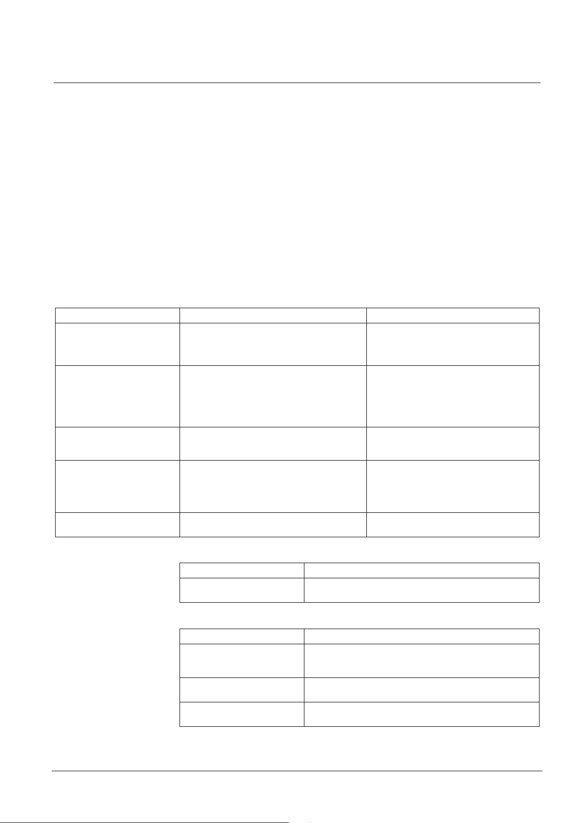
Target audience
This document and the information contained therein are aimed at the target
groups defined below:
Personnel Activity Qualification
Product manager – Performs local product management
– Responsible for exchanging information
between the headquarters and his/her Regional
Company (RC) for his/her product range
Project manager – Performs project management
– Coordinates the use of all persons and
resources involved in the project according to
schedule
– Continuously supplies information necessary for
project realisation
Installer – Assembles and installs the components at the
place of installation
– Performs a subsequent check of the installation
Commissioning personnel – Configure the product at the place of installation
according to customer specific requirements
– Check the product operability and release the
product for use by the operator
– Search for and correct malfunctions
Maintenance personnel – Carry out all maintenance work and check for
correct functioning
– Has suitable specialist training for the
function and for the product range
– Has attended the PM training courses
– Has suitable specialist training for the
– function, scale of the project and product
range
– Has attended the training courses for
Project Managers
– Has received specialized training in the area
of building installation technology or
electrical installations
– Has suitable specialist training for the
function and for the product range
– Have attended the training courses for
commissioning personnel
– Has suitable specialist training for the
function and for the product range
About this document
Reference documents
Designation Heading
A6V10257477_a_fr XC10 range
Operating manual
Identification of the document
Location Definition
Title page – Short name
Last page bottom left-hand side – Document no. (number-modification index-language-country)
Last page bottom right-hand
side
Building Technologies A6V10257473_b_en_--.doc
Fire Safety & Security Products 01.2010
– Name in full
– Document purpose
– Date of issue
– User's guide
– Register
7
Page 8
About this document
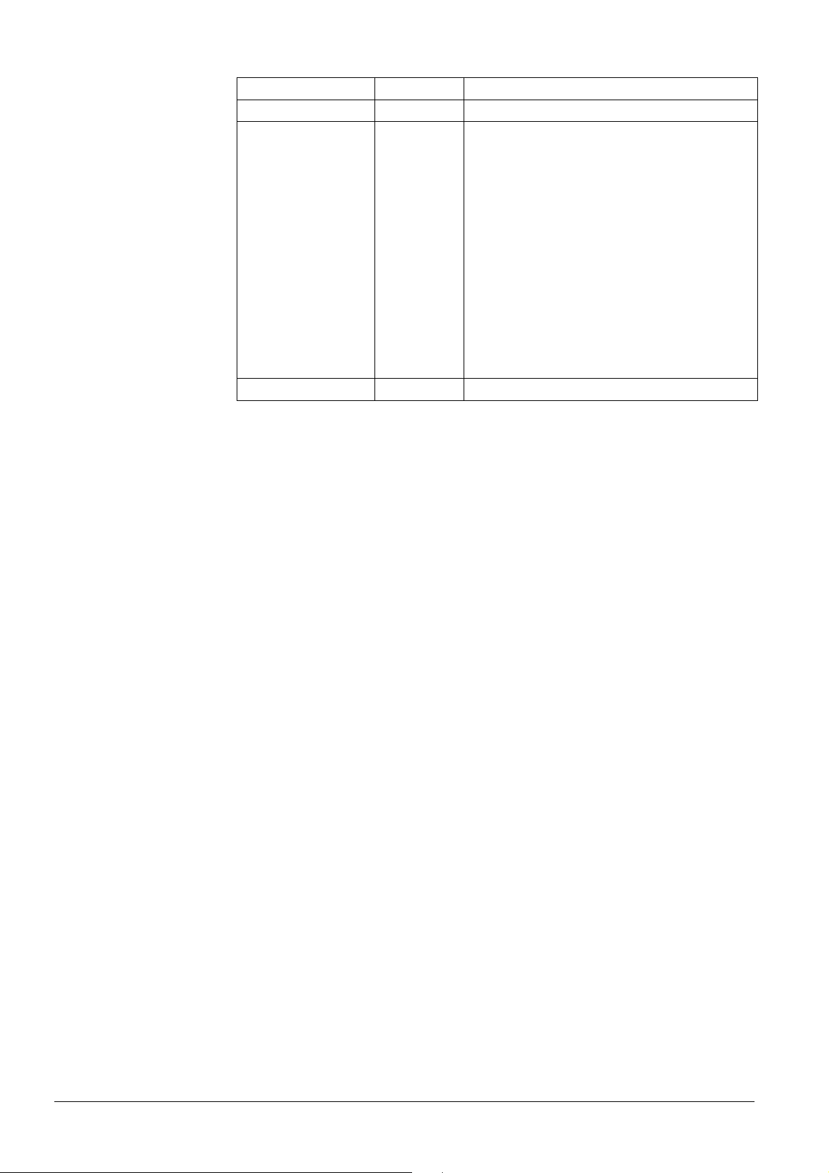
Revision history
Document no. Edition date Brief description
A6V10257473_a_en_-- 11/2009 First edition MP2.1
A6V10257473_b_en_-- 01/2010 Corrections after field tests:
- Chap. 3: Standards / 4.19 monitoring the status of
components (spelling mistake)
- Chap.4: fig 4 updated
- Chap. 6.3 label for XC1003-A is Pos. 8 not Pos.4
- Chap. 7.6.2 …. “to equipment outside” (spelling
mistake)
- Chap 7.8: 24V polarity output was wrong. 24V(+) is on
X5-3 and 24V(-) is on X5-4
- Chap. 8.2: note added for the connection of the 24V
power supply
- Chap 8.3: fig 31 modified: resistor 3.3k on RS485 line
removed
- Chap 11: fig 33 and 34 updated
- Chap 14.2: PMI picture is added on the top of the
description table, for an easier checking
- Chap. 16.2: access code for the alarm counter was
wrong
- Spelling mistakes
8
Building Technologies A6V10257473_b_en_--.doc
Fire Safety & Security Products 01.2010
Page 9
2 Safety instructions
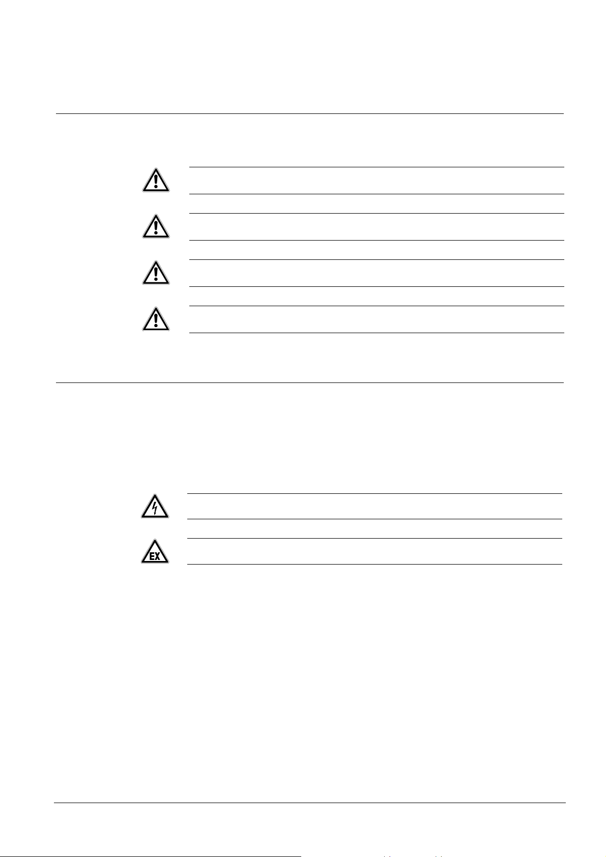
2.1 Danger levels
The following pictograms indicate the possible danger levels, their severity and
consequences.
DANGER
WARNING
CAUTION
NOTE
Safety instructions
Imminent danger!
Serious injuries or death.
Potentially dangerous situation
Serious injuries or death.
Potentially dangerous situation
Light injuries or material damage.
Important information requiring special attention.
2.2 Safety instructions
Products are developed and manufactured in accordance with the applicable
international and European security standards.
The local rules of installation, exploitation and destruction of the product apply and
must be respected just like the safety instructions which appear in the
documentation of the product.
Electric installations
CAUTION
CAUTION
Hardware must not be powered during commissioning and maintenance
Affix an external label “DANGER external voltage” on the terminals connected to
an external voltage source
Separately lay the power lines towards the control unit. They must be fitted with
their own, clearly identified fuses
Ground in accordance with the local security standards
Interventions on wiring should be carried out only by qualified personnel.
Respect the safety instructions in explosive zone.
Assembly, installation, commissioning and maintenance
If any tools or accessories such as ladders are required, safe and suitable
devices must be used
When the extinguishing control panel is started up, it must be ensured that no
instable conditions can occur
Controls may only be set to normal function when the product operability has
been completely tested and the system has been handed over to the customer.
Control release for testing should not damage the installation
9
Building Technologies A6V10257473_b_en_--.doc
Fire Safety & Security Products 01.2010
Page 10

Safety instructions
Avoid the inopportune release of RT-alarm
Inform the reception station before an RT-alarm test
Installation and commissioning shall be performed by trained personal
Product operation check
Inform the personnel of the formation of a smoke cloud and presence of noise
Inform the personnel before alarm devices check and anticipate possible panic
reactions
Warn the alarm reception centers and the fault reception stations connected to
the system before carrying out the tests
Design modifications of systems and products
Modifications to the system and to individual products may lead to faults,
malfunctioning and safety risks
Intended system modifications or extensions require written approval from
Siemens and the relevant safety authorities
Components and spare parts
Components and spare parts must comply with the technical specifications
defined by Siemens. Only use products recommended or prescribed by Siemens
Only use fuses with the specified fuse characteristics
Wrong battery types and improper battery changing lead to a risk of explosion.
Only use the same battery type or an equivalent type recommended by Siemens
Batteries must be disposed of in an environmentally friendly manner. Country
specific directives and regulations must be observed. They must be deposited at
the collection places assigned to this purpose.
Note that the cylinders containing the extinguishing agent are under pressure
and that they must consequently be replaced in accordance with the safety
instructions in force
Disregard of the safety regulations
Before they are delivered, products are tested to ensure they function correctly
when used properly. Siemens disclaims all liability for damage or injuries caused
by the incorrect application of the instructions or the disregard of danger warnings
contained in the documentation. This applies in particular to:
Personal injuries or damage to property caused by improper use and incorrect
application
Personal injuries or damage to property caused by disregarding safety
instructions in the documentation or on the product
Personal injury or damage to property caused by poor maintenance or lack of
maintenance
2.3 Standards and directives complied with
A list of the standards and directives complied with is available at your Siemens
contact partner.
10
Building Technologies A6V10257473_b_en_--.doc
Fire Safety & Security Products 01.2010
Page 11

3 Standards
In addition to the requirements of EN12094-1 and EN54-2, the XC10xx-A control
panel complies with the following optional functions:
EN 12094-1
Clause Description
4.17 Delay of extinguishing signal
4.18 Signal representing the flow of extinguishing agent
4.19 Monitoring the status of components
4.20 Emergency hold device
4.21 Control of flooding time
4.23 Manual only mode
4.24 Triggering signals to equipment within the system
4.26 Triggering of equipment outside the system
4.27 Emergency abort device
4.29 Release of the extinguishing media for selected flooding zones (only for XC1003-A)
4.30 Activation of alarm device with different signals
EN 54-2 / A1
Clause Description
7.8 Output to fire alarm devices (Item C – EN54-1)
7.9.1 Control of fire alarm routing equipment (Item E – EN54-1)
7.12.1 Dependencies on more than one alarm signal (Type A)
7.13 Alarm counter (only with XC1005-A)
8.3 Fault signals from point
8.4 Total loss of the power supply
8.9 Output to fault warning routing equipment (Item J – EN54-1)
10 Test condition
Following additional functions are also available:
- transmission of information's outside the panel:
8 programmable digital outputs
programmable relay contacts
- reception of information's from outside:
control inputs (3 are programmable)
- 24V power supply output
Standards
11
Building Technologies A6V10257473_b_en_--.doc
Fire Safety & Security Products 01.2010
Page 12
Overview
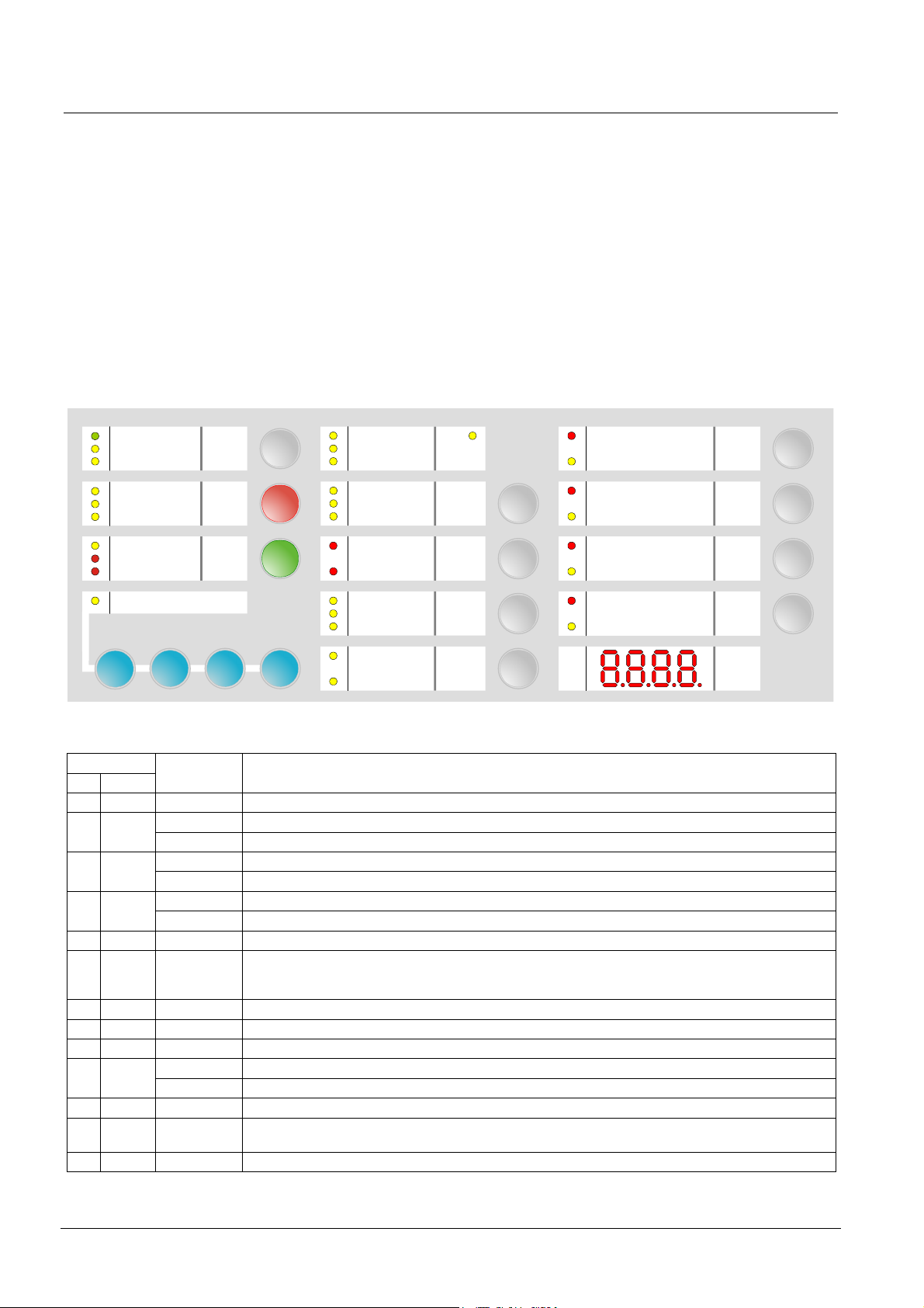
4 Overview
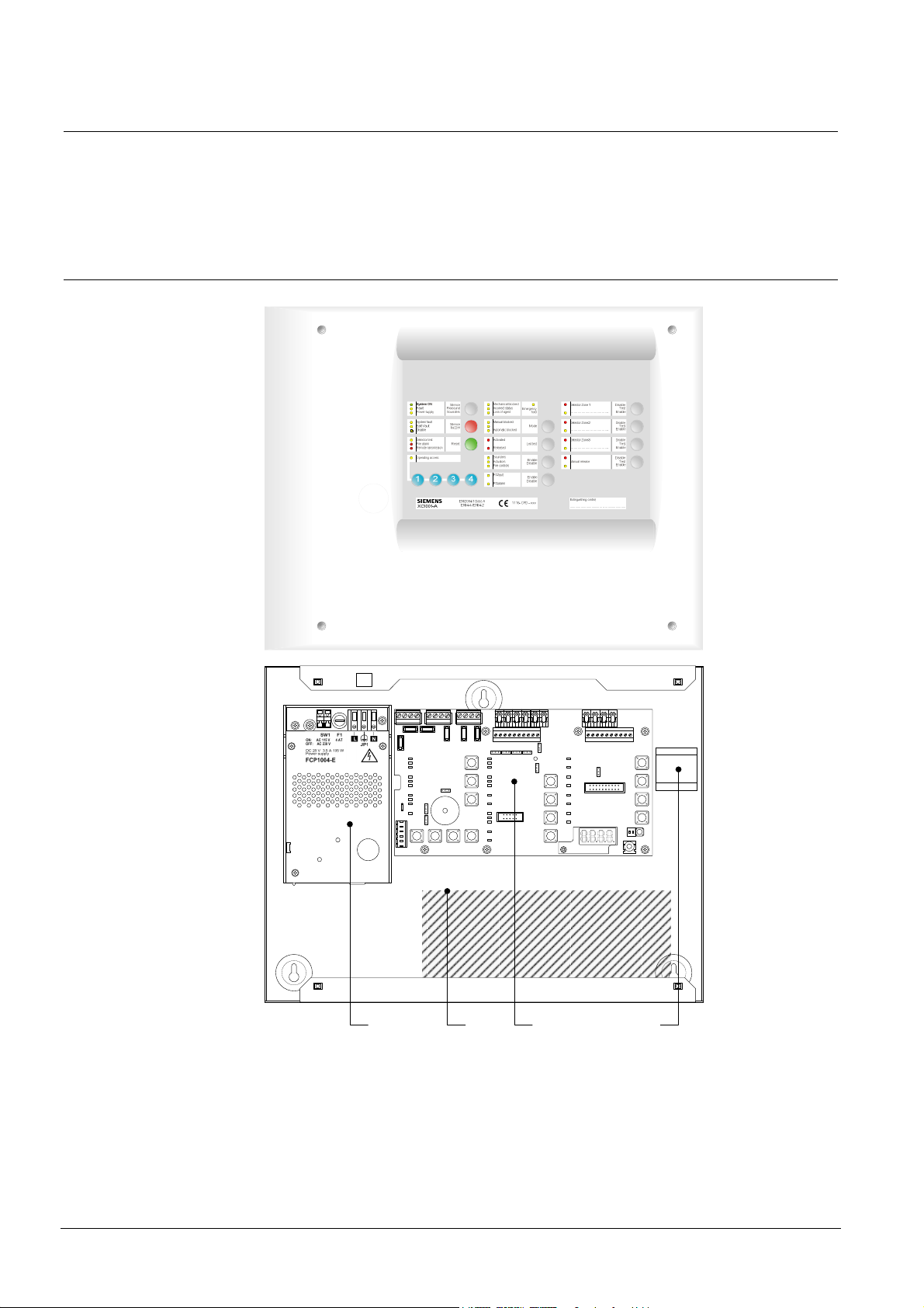
4.1 XC1001-A
The equipment is declined in 3 versions:
- Wall mounting cabinet: XC1001-A / XC1005-A
- 19” rack cabinet: XC1003-A
ON
1 2
3 421
Fig. 1 XC1001-A
1 FCP1004-E power supply unit with charger
2 XCM1002 mainboard
3 4.5 A/h batteries
4 DIN rail for accessory mounting (Z3B171 relay module)
12
Building Technologies A6V10257473_b_en_--.doc
Fire Safety & Security Products 01.2010
Page 13
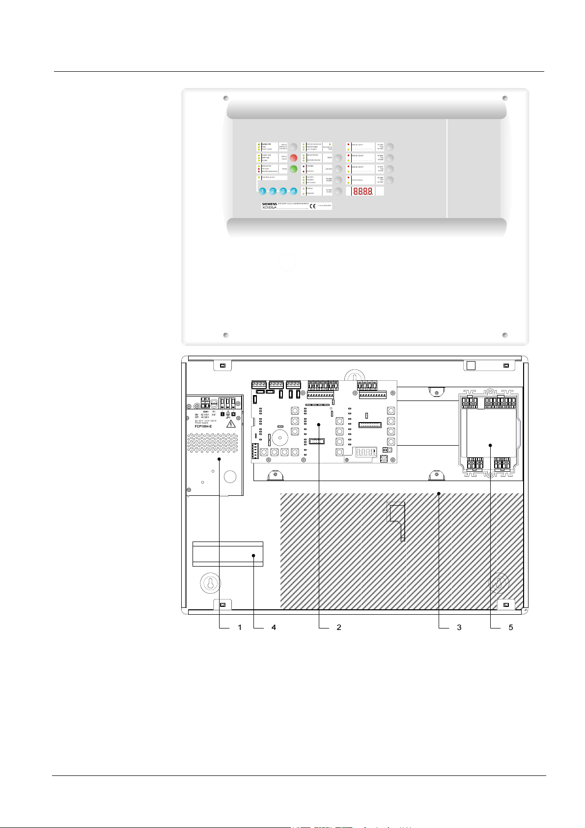
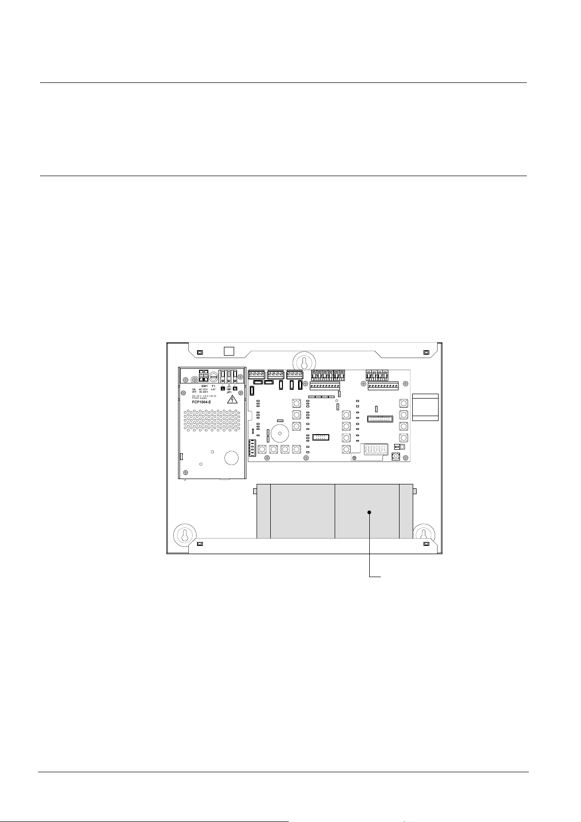
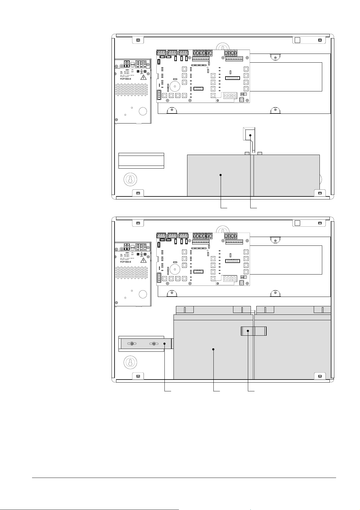
4.2 XC1005-A
Overview
Fig. 2 XC1005-A
1 FCP1004-E power supply unit with charger
2 XCM1002 mainboard
3 17 A/h batteries
4 DIN rail for accessory mounting (Z3B171 relay module)
5 FDCI / FDCIO222 module for the connection to a fire detection system
(option)
13
Building Technologies A6V10257473_b_en_--.doc
Fire Safety & Security Products 01.2010
Page 14
Overview
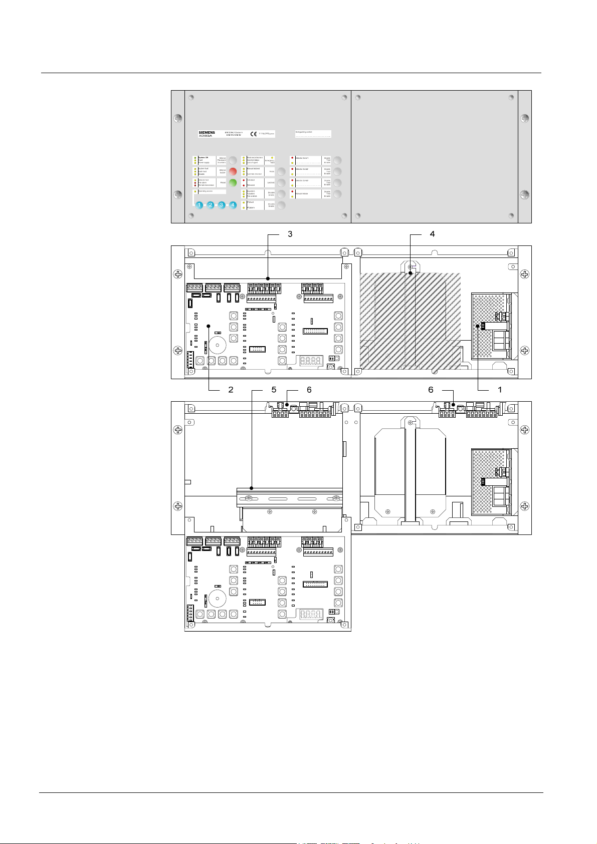
4.3 XC1003-A
Fig. 3 XC1003-A
1 FCP1004-E power supply unit with charger
2 XCM1002 mainboard
3 Removable mainboard holder
4 4.5 A/h or 7.2 A/h batteries
5 DIN rail for accessory mounting (Z3B171 relay module, XCA1030 multi-sector
modules, etc.)
6 FDCI / FDCIO222 module for the connection to a fire detection system
(option)
14
Building Technologies A6V10257473_b_en_--.doc
Fire Safety & Security Products 01.2010
Page 15

4.4 FCP1004-E
Overview
Fig. 4 FCP1004-E power supply unit
Mark Function Remarks
1 Mains voltage setting Shunt ON = 115VCA, shunt OFF = 230VCA
2 Mains terminal block
3 Mains fuse 4A / 250V
4 System start without mains power Shunt the 2 terminals with a jumper and
5 Temperature sensor for battery charging voltage compensation Do not cover
6 Internal green LED «Mains operation» but visible from the front Not lit if no mains voltage
7 Battery connection
8 XCM1002 main board connection
remove after system start
Security level of terminal blocks 1 and 2: Dangerous voltage
Security level of other terminal blocks: SELV (Safety Extra Low Voltage)
15
Building Technologies A6V10257473_b_en_--.doc
Fire Safety & Security Products 01.2010
Page 16
Overview
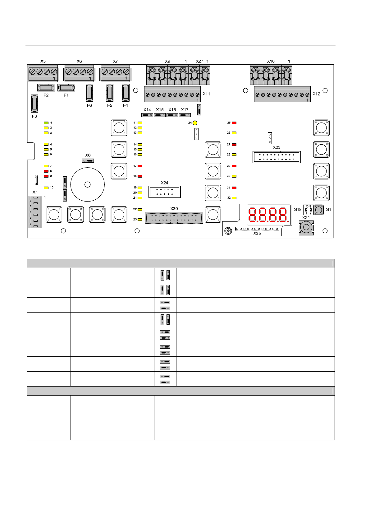
4.5 XCM1002
X13
X18
X28
X3X4
X26
Fig. 5 XCM1002 board
Setting elements
X3 Internal buzzer Enable/Disable
X4 Type of power supply
X8 Operating access Level 2
X13 Relay contact type 1
(NO or NC)
X14 Relay contact type 5
(NO or NC)
X15 Relay contact type 4
(NO or NC)
X16 Relay contact type 3
(NO or NC)
X17 Relay contact type 2
(NO or NC)
Other elements
F1 / F2 Pluggable fuse 2 AF Fuse for protection of control outputs 4 (F1) and 5 (F2)
F3 Pluggable fuse 1 AF Fuse for protection of 24V output
F4 / F5 / F6 Pluggable fuse 1 AT Fuse for protection of control outputs 1 (F4), 2 (F5) and 3 (F6)
S1 Reset —
S18-1 / S18-2 Not used Do not change (factory setting : OFF)
Jumper up (factory setting) : buzzer enabled
Jumper down : buzzer disabled (only for servicing)
Jumper up (factory setting) : FCP1004-E
Jumper down : do not use (for further use of external power supply)
Jumper on the right (factory setting) : Level 2 access using code
Jumper on the left : Level 2 access permanent
Jumper up : NC contact
Jumper down (factory setting) : NO contact
Jumper on the right : NC contact
Jumper on the left (factory setting) : NO contact
Jumper on the right : NC contact
Jumper on the left (factory setting) : NO contact
Jumper on the right : NC contact
Jumper on the left (factory setting) : NO contact
Jumper on the right : NC contact
Jumper on the left (factory setting) : NO contact
16
Building Technologies A6V10257473_b_en_--.doc
Fire Safety & Security Products 01.2010
Page 17
Overview
PCB terminal blocks
(1.5 mm2 max.)
(2.5 mm2 max.)
(2.5 mm2 max.)
(2.5 mm2 max.)
X9 Plug-in block 8 points
X10 Plug-in block 8 points
X11 Plug-in block 10 points
X21 Jack 2.5 mm — Maintenance PC
X28 Faston 5.3 mm (+) To positive of battery (to provide “Total loss of power supply”
X30 (*) Flat cable 26 points — Connection for multi-sector module XCA1030
X35 Terminal 12 points — Connection for 4 digits display
X18, 23, 24,
26
(*) on welding side
Note 1: The XC10 provides the EN54-2 option with requirement 8.4 called “Total loss of power”. This option when selected activates the
(1.5 mm2 max.)
(1.5 mm2 max.)
(1.5 mm2 max.)
(1.5 mm2 max.)
(1.5 mm2 max.)
Not used — —
system fault LED and the buzzer continuously, for at least 1 hour after a low discharge battery disconnection. The option can be
selected by wiring the +BAT terminal to the positive voltage of batteries (use of remaining power after battery disconnection).
1-2 (–) / 5-6 (+) 24V power supply X1 Plug-in block 6 points
3-4 (+) Power supply monitoring
1 (+) / 2 (–) Monitored output 5 X5 Plug-in block 4 points
3 (+) / 4 (–) 24V use output
1 (+) / 2 (–) Monitored output 3 (control polarities, reversed in standby) X6 Plug-in block 4 points
3 (+) / 4 (–) Monitored output 4
1 (+) / 2 (–) Monitored output 1 (control polarities, reversed in standby) X7 Plug-in block 4 points
3 (+) / 4 (–) Monitored output 2 (control polarities, reversed in standby)
1 (+) / 2 (–) Monitored input 1
3 (+) / 4 (–) Monitored input 2
5 (+) / 6 (–) Monitored input 3
7 (+) / 8 (–) Monitored input 4
1 (+) / 2 (–) Fire detectors zone 1
3 (+) / 4 (–) Fire detectors zone 2
5 (+) / 6 (–) Fire detectors zone 3
7 (+) / 8 (–) Extinguishing manual control
1 / 2 Potential-free contact relay 1 (NO or NC)
3 / 4 Potential-free contact relay 2 (NO or NC)
5 / 6 Potential-free contact relay 3 (NO or NC)
7 / 8 Potential-free contact relay 4 (NO or NC)
9 / 10 Potential-free contact relay 5 (NO or NC)
1 … 8 (–) Logical outputs 1 to 8 X12 Plug-in block 10 points
9 / 10 Not used
1 (+) Reset X27 Plug-in block 4 points
2 … 4 (+) Unmonitored inputs 2 to 4
function (see note 1)
17
Building Technologies A6V10257473_b_en_--.doc
Fire Safety & Security Products 01.2010
Page 18
Overview
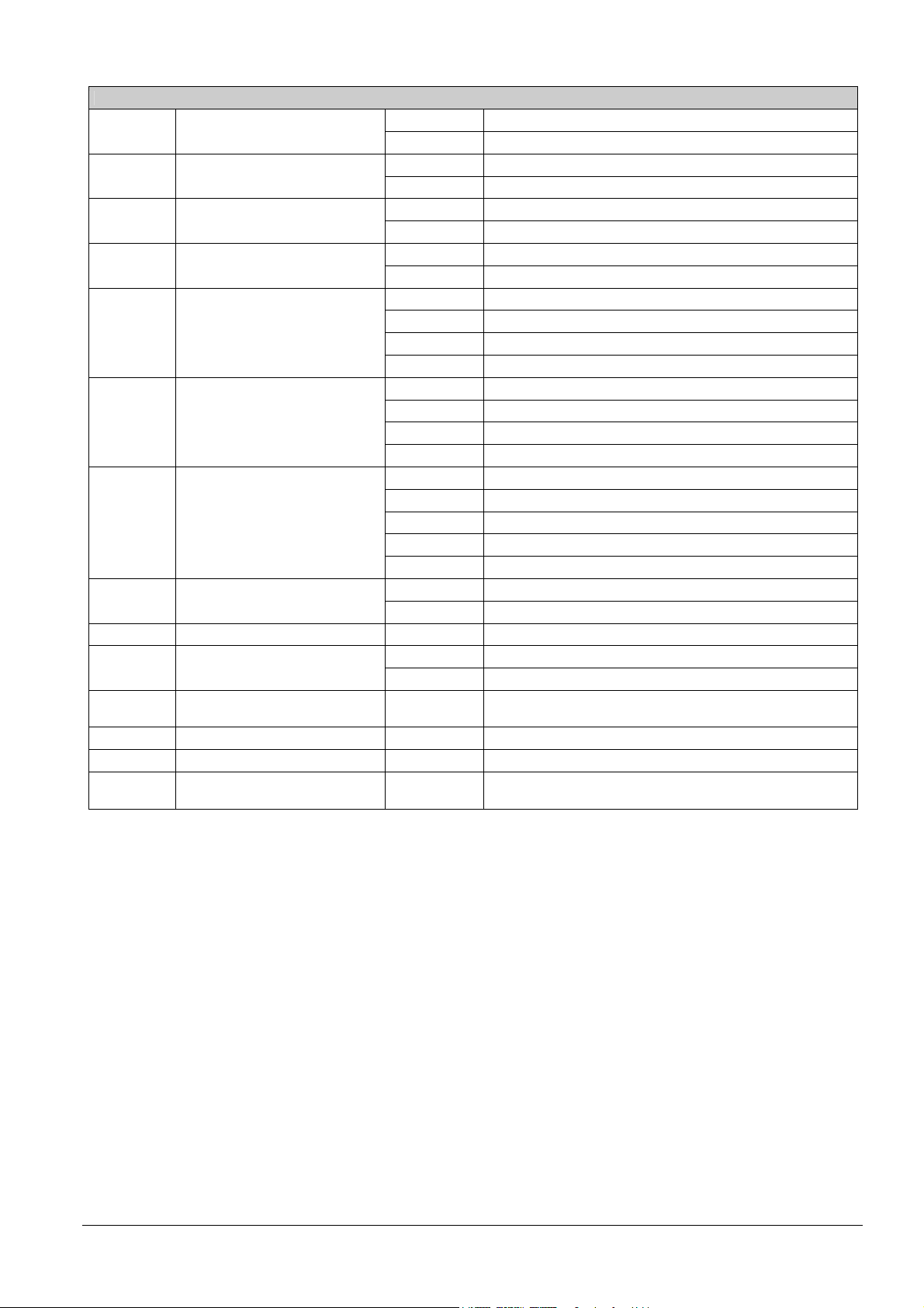
4.6 User interface
All display and control elements, except 4-digit display for XC1001-A and XC1003-A
versions, are accessible to the user:
- Led 1 to 32 indicators for operating condition,
- Keys 1 to 15 allowing :
operating access
operation (reset, off, test, etc)
system test
user functions programming
- 4-digit display showing:
programming steps and options
pre-warning time count down
other information’s (calibration states, alarm counter, etc)
System ON
1
Fault
2
Power supply
3
System fault
4
Earth fault
5
Disable
6
Detector test
7
Fire alarm
8
Remote transmission
9
Operating access
10 19
1
Silence
Re-sound
Sounders
Silence
buzzer
Reset
5 2
6
7
432
11
12
13
14
15
16
17
18
20
21
22
23
Mechanical blocked
Incorrect status
Loss of agent
Manual blocked
Automatic blocked
Activated
Released
Sounders
Actuators
Fire controls
RT-fault
RT-alarm
Emergency
hold
Mode
Led test
Disable
Enable
Disable
Enable
24
10
25
Detector Zone 1
………………………………….
26
27
8
9
Detector Zone 2
……………………………………
28
29
Detector Zone 3
……………………………………
30
31
Manual release
32
11
Fig. 6 XC10xx-A, user interface
Indicators
N° Color
1 Green Fixed The control panel is in operation
5 Yellow Fast At least one component connected to the control panel is grounded
6 Yellow Fixed – At least one component in the system is disabled
7 Yellow Slow At least one detection zone and/or extinguishing manual control is being tested
8 Red Fixed At least one detection zone is in alarm
9 Red Fixed Remote transmission activated (*)
11 Yellow Fixed Mechanical blocking device is in the blocked position
12 Yellow Fast – Mechanical blocking device is in a wrong position
13 Yellow Fast Loss of agent
(*) According to programming
State Description
Fixed The control panel is not able to function any more 2 Yellow
Fast Fault on at least one component in the system (see paragraph 14.2 for the detail)
Slow Mains fault 3 Yellow
Fast Batteries fault
Fixed Microprocessor fault 4 Yellow
Slow Jumper buzzer (X3 - XCM1002 board) not connected (remainder)
– Calibration in progress or error
– Programming in progress
Fixed Level 2 operating access granted 10 Yellow
Slow System test activated
– Selector valve is in a wrong position (used for multi-sector applications)
Disable
Test
Enable
Disable
Test
Enable
Disable
Test
Enable
Disable
Test
Enable
12
13
14
15
18
Building Technologies A6V10257473_b_en_--.doc
Fire Safety & Security Products 01.2010
Page 19

Indicators
N° Color
State Description
14 Yellow Fixed – Manual release is blocked or being tested
15 Yellow Fixed – Standard = not used
– Alternative = automatic and manual release granted (UK)
16 Yellow Fixed – Automatic release is blocked
– At least one detection zone which starts the extinguishing is off or being tested
17 Red
Fixed – All detection zones which start the extinguishing are in alarm condition
– One of the electrical manual triggering device (DM1103-L) is actuated
Fast One of the detection zones which start the extinguishing is in alarm condition
Fixed Extinguishing agent is released 18 Red
Slow / Fast Discharged contact is not activated within 30 seconds after actuators control (*)
19 Yellow
Fixed Sounders are disabled
Slow Sounders test is in progress (real activation)
Fast At least, an output programmed as Sounders is in fault condition (break or short-circuit)
20 Yellow
Fixed Actuators are disabled
Slow Actuators test is in progress (simulated activation)
Fast – At least, one output programmed as actuators is in fault condition (break or short-circuit)
– Calibration in progress or error or no calibration data
21 Yellow
Fixed Fire controls are disabled
Slow Warning panels test is in progress (real activation)
Fast At least, one output programmed as fire controls is in fault condition (break or short-circuit)
Fixed RT-fault is disabled 22 Yellow
Slow RT-fault test is in progress (real activation)
23 Yellow
Fixed RT-alarm is disabled
Slow RT-alarm test is in progress (real activation)
Fast At least, one output programmed as RT-alarm is in fault condition (break or short-circuit)
24 Yellow
Fixed Emergency abort is activated
Slow Emergency hold is activated (DM1101-S)
Fast At least, one input programmed as emergency hold/abort is in fault condition (break or short-circuit)
Fixed Detection zone 1 is in alarm condition 25 Red
Slow Detection zone 1 is in alarm condition (first alarm)
Fixed / Slow Detection zone 1 is disabled (fixed) / being tested (slow) 26 Yellow
Fast Detection zone 1 is in fault condition (break or short-circuit)
Fixed Detection zone 2 is in alarm condition 27 Red
Slow Detection zone 2 is in alarm condition (first alarm)
Fixed / Slow Detection zone 2 is disabled (fixed) / being tested (slow) 28 Yellow
Fast Detection zone 2 is in fault condition (break or short-circuit)
Fixed Detection zone 3 is in alarm condition 29 Red
Slow Detection zone 3 is in alarm condition (first alarm)
Fixed / Slow Detection zone 3 is disabled (fixed) / being tested (slow) 30 Yellow
Fast Detection zone 3 is in fault condition (break or short-circuit)
Fixed Manual release is activated (DM1103-L line) 31 Red
Slow Manual release is activated (DM1103-L line) – First alarm
Fixed / Slow Manual release is disabled (fixed) / being tested (slow) 32 Yellow
Fast Manual release is in fault condition (break or short-circuit)
(*) According to programming
Overview
19
Building Technologies A6V10257473_b_en_--.doc
Fire Safety & Security Products 01.2010
Page 20

Overview
Keys Description
1 … 4 Operating access code input (level 2, programming, system test, etc.)
5 Silence / Restart sounders by successive pressing:
– 1st pressing: silence sounders
– 2nd pressing: restart sounders
– 3rd pressing: silence sounders
– etc
Operating access level required for this operation = level 2 (silence sounders is not possible during pre-warning time)
6 Silence buzzer
Operating access level required for this operation = level 1 or 2 or 2 only (*)
7
8 Mode of operating, by successive pressing:
9 Led and buzzer test (duration = 6 seconds) :
10 Disable / Enable by successive pressing:
11 Disable / Enable by successive pressing:
12 Disable / Enable by successive pressing (not possible in case of fault or alarm):
13 Disable / Enable by successive pressing (not possible in case of fault or alarm):
14 Disable / Enable by successive pressing (not possible in case of fault or alarm):
15 Disable / Enable by successive pressing (not possible in case of fault or alarm):
(*) According to programming
1) Reset of the system. Reset is not possible :
– during pre-warning time, emergency stop and flooding time
– if buzzer and/or sounders are not silenced
– if manual release button and/or discharged contact are not reset (*)
Operating access level required for this operation = level 2
2) Fault reset (*)
Operating access level required for this operation = level 2
– 1st pressing: automatic blocked
– 2nd pressing: automatic and manual blocked
– 3rd pressing: normal mode
Operating access level required for these operations = level 2
All led indicators are activated and the buzzer sounds continuously (during the first three seconds, all the segments of the
display are activated, then the SW version is displayed)
Operating access level required for this operation = level 1
– 1st pressing: actuators are disabled
– 2nd pressing: sounders and actuators are disabled
– 3rd pressing: fire controls are disabled
– 4th pressing: all is disabled
– 5th pressing: all is enabled
Operating access level required for these operations = level 2
– 1st pressing: RT-fault is disabled
– 2nd pressing: RT-fault is enabled / RT-alarm is disabled
– 3rd pressing: RT-fault and RT-alarm are disabled
– 4th pressing: all are enabled
Operating access level required for these operations = level 2
– 1st pressing: zone 1 is disabled
– 2nd pressing: zone 1 is tested
– 3rd pressing: zone 1 is in normal condition
Operating access level required for these operations = level 2
– 1st pressing: zone 2 is disabled
– 2nd pressing: zone 2 is tested
– 3rd pressing: zone 2 is in normal condition
Operating access level required for these operations = level 2
– 1st pressing: zone 3 is disabled
– 2nd pressing: zone 3 is tested
– 3rd pressing: zone 3 is in normal condition
Operating access level required for these operations = level 2
– 1st pressing: manual release is disabled
– 2nd pressing: manual release is tested
– 3rd pressing: manual release is in normal condition
Operating access level required for these operations = level 2
20
Building Technologies A6V10257473_b_en_--.doc
Fire Safety & Security Products 01.2010
Page 21

5 Features
Power supply (FCP1004-E)
XCM1002
Detection lines
Manual release line
Monitored inputs
Control inputs (non
monitored)
Monitored control outputs
Outputs 1 to 3
Driver outputs
Relay outputs (contacts)
Connections
Environmental conditions
Mechanical data
Conformity
Primary source (mains)
Voltage
Current
Power
Secondary source (batteries)
Connectable batteries
Voltage
Charging current max.
Internal resistance max.
Deep discharge (disconnection threshold)
Output
Voltage
Max. available current
Min. current
Power
Switching frequency / Ripple
Input voltage
Current consumption
I/Os security level
Type / number of detectors
Compatible detectors
End of line element (EOL)
Standby condition voltage / current
Alarm condition voltage / current
Line resistance
Type / number of manual actuators
End of line element (EOL)
Voltage / standby line current
Voltage / alarm line current
Line resistance
4
Activation resistance
End of line element (EOL)
Line resistance
4 Activation +24 V, via contact
Outputs 1 to 3
Control voltage / current
End of line element
Outputs 4 and 5
Control voltage / current
End of line element
8 (programmable) 24 V / 40 mA max.
5 (4 programmable) 30 V / 1 A max. / NO or NC
XCM1002
Inputs - outputs type / section
FCP1004-E
mains input type / section
Operating / Storage temperature
Humidity relative at 40 ± 2° C
XC1001-A Cabinet / Protection index
XC1005-A Cabinet / Protection index
XC1003-A Cabinet / Protection index
EN 12094-1, EN 54-2/A1, EN 54-4/A2 —
Color
Dimensions (l x h x p) / Weight
Color
Dimensions (l x h x p) / Weight
Color
Dimensions (l x h x p) / Weight
Features
115 / 230 VCA +10 …-15% – 50 / 60 Hz
1.75 A max.
150 VA max.
2 x 12 V / 4.5 … 17 Ah
23.4 … 27.6 V
1.3 A (with temperature compensation)
1 Ω
20 V +/-3%
27.3 V +/- 0.3 V (25°C)
Imax a : 2 A (batteries loading)
Imax b : 3.5 A (batteries loaded)
0.05 A
105 W max.
132kHz / 70 mVpp max.
22.5 … 27.6 V (25°C)
190 mA max. without primary source
SELV (Safety Extra Low Voltage)
Collective / 32 max. (according to detector type)
Siemens (Algorex, Sinteso, Synova)
Transzorb 18 V (P6KE18CA)
17.1 … 19.3 V (fixed by EOL) / 11 mA max.
5.5 … 16.5 V / 11 … 57.1 mA max.
80 Ω max.
DM1103-L / 32 max.
Transzorb 18 V (P6KE18CA)
17.1 … 19.3 V (fixed by EOL) / 11 mA max.
5.5 … 16.5 V / 11 … 57.1 mA max.
80 Ω max.
680 Ω or 1.2 kΩ
3.3 kΩ resistance
80 Ω max.
24 V / 1 A max.
3.3 kΩ resistance
24 V / 2 A max.
No EOL (line calibration)
Plug-in screw terminal blocks
2.5 mm2 max. (X5, X5, X7)
1.5 mm2 max. (all others)
Plug-in screw terminal block / 2.5 mm2 max.
-5 ... +40° C / -20 ... +60° C
93% max., without condensation
Metal frame with plastic cover / IP30
RAL9003 (cover), RAL9006 (user interface)
370 x 286 x 90 mm / 4.1 kg
Metal case with plastic cover / IP40
RAL9003 (cover), RAL9006 (user interface)
505 / 375 / 125 mm / 6.5 kg
Rack 19’’ 4U / IP30
RAL9006
482.6 (19’’) x 177.8 (4U) x 187 mm / 6.6 kg
21
Building Technologies A6V10257473_b_en_--.doc
Fire Safety & Security Products 01.2010
Page 22
Installation
6 Installation
6.1 XC1001-A / XC1005-A
Generally, the XC10 must be easily accessible and installed:
- outside the protected area
- protected from mechanical shocks and bad weather
The XC10 must be installed on a fixed and stable support, with a height ranging
between 1.60 m and 1.70 m (eliminate the irregularities from the mounting surface
≥ 5 mm).
1. Remove front cover
2. Mark and drill the mounting holes using the drilling template provided (start with
the hole for the top central screw)
3. Fix the chassis using 3 screws Ø 4 x 50 mm (not provided)
4. Cut out the cable entries
5. Cut out the plastic housing according to the cable inputs (XC1001-A)
6. Mount the cable glands is necessary (required for protection rating IP30)
7. Install the batteries and fix the battery holders
ON
1 2
1
1 12 V – 4.5 Ah batteries
Fig. 7 XC1001-A, battery installation
22
Building Technologies A6V10257473_b_en_--.doc
Fire Safety & Security Products 01.2010
Page 23
Installation
ON
1 2
1 4
ON
1 2
23 3 (insert in slot 4)
1 12 V – 12 Ah batteries
2 12 V – 17 Ah batteries
3 FCA1014 battery holder (option)
4 Slot for battery holder
Fig. 8 XC1005-A, battery installation
23
Building Technologies A6V10257473_b_en_--.doc
Fire Safety & Security Products 01.2010
Page 24

Installation
6.2 XC1003-A
Fix the XC1003-A into a 19'' housing cabinet with a protection rating IP ≥ 30.
Cover
ZONE EXTINCTION :
EN12094-1 Classe A
s
1116 -CPD– xxx
EN54-4 / EN54-2
XC1003-A
Sous tension
Arrêt /
Marche
Défaut général
sirènes
Défaut alimentation
Système hors service
Arrêt
signal
Défaut terre
sonore
Hors service
Essai
Réar-
Alarme feu générale
mement
Télé-transmission
Niveau 2
1
s
XC1003-A
Sous tension
Arrêt /
Marche
Défaut général
sirènes
Défaut alimentation
Système hors service
Arrêt
signal
Défaut terre
sonore
Hors service
Essai
Réar-
Alarme feu générale
mement
Télé-transmission
Niveau 2
s
XC1003-A
Sous tension
Arrêt /
Marche
Défaut général
sirènes
Défaut alimentation
Système hors service
Arrêt
signal
Défaut terre
sonore
Hors service
Essai
Réar-
Alarme feu générale
mement
Télé-transmission
Niveau 2
s
XC1003-A
Sous tension
Arrêt /
Marche
Défaut général
sirènes
Défaut alimentation
Système hors service
Arrêt
signal
Défaut terre
sonore
Hors service
Essai
Réar-
Alarme feu générale
mement
Télé-transmission
Niveau 2
s
XC1003-A
Sous tension
Arrêt /
Marche
Défaut général
sirènes
Défaut alimentation
Système hors service
Arrêt
signal
Défaut terre
sonore
Hors service
Essai
Réar-
Alarme feu générale
mement
Télé-transmission
Niveau 2
1
……………………………………………………..
Blocage mécanique
Zone 1
Etat incorrect
Perte agent
Manuel bloqué
Non utilisé
Automatique bloqué
Evacuation
Emission
Sirènes
Déclencheurs
Asservissements
Report de défaut
432
Report d’alarme
EN12094-1 Classe A
EN54-4 / EN54-2
Blocage mécanique
Etat incorrect
Perte agent
Manuel bloqué
Non utilisé
Automatique bloqué
Evacuation
Emission
Sirènes
Déclencheurs
Asservissements
Report de défaut
4321
Report d’alarme
EN12094-1 Classe A
EN54-4 / EN54-2
Blocage mécanique
Etat incorrect
Perte agent
Manuel bloqué
Non utilisé
Automatique bloqué
Evacuation
Emission
Sirènes
Déclencheurs
Asservissements
Report de défaut
4321
Report d’alarme
EN12094-1 Classe A
EN54-4 / EN54-2
Blocage mécanique
Etat incorrect
Perte agent
Manuel bloqué
Non utilisé
Automatique bloqué
Evacuation
Emission
Sirènes
Déclencheurs
Asservissements
Report de défaut
4321
Report d’alarme
EN12094-1 Classe A
EN54-4 / EN54-2
Blocage mécanique
Etat incorrect
Perte agent
Manuel bloqué
Non utilisé
Automatique bloqué
Evacuation
Emission
Sirènes
Déclencheurs
Asservissements
Report de défaut
432
Report d’alarme
Hors
Essai
2
Arrêt
……………………………………..
En
d’urgence
Zone 2
Hors
Mode
Essai
……………………………………..
En
Zone 3
Hors
Test
Essai
signal.
……………………………………..
En
Hors
Hors
Commande manuelle
Essai
En
En
Hors
En
ZONE EXTINCTION :
1116 -CPD– xxx
……………………………………………………..
Zone 1
Hors
Essai
Arrêt
2
……………………………………..
En
d’urgence
Zone 2
Hors
Mode
Essai
……………………………………..
En
Zone 3
Hors
Test
Essai
signal.
……………………………………..
En
Hors
Hors
Commande manuelle
Essai
En
En
Hors
En
ZONE EXTINCTION :
1116 -CPD– xxx
……………………………………………………..
Zone 1
Hors
Essai
2
Arrêt
……………………………………..
En
d’urgence
Zone 2
Hors
Mode
Essai
……………………………………..
En
Zone 3
Hors
Test
Essai
signal.
……………………………………..
En
Hors
Hors
Commande manuelle
Essai
En
En
Hors
En
ZONE EXTINCTION :
1116 -CPD– xxx
……………………………………………………..
Zone 1
Hors
Essai
2
Arrêt
……………………………………..
En
d’urgence
Zone 2
Hors
Mode
Essai
……………………………………..
En
Zone 3
Hors
Test
Essai
signal.
……………………………………..
En
Hors
Hors
Commande manuelle
Essai
En
En
Hors
En
ZONE EXTINCTION :
1116 -CPD– xxx
……………………………………………………..
Zone 1
Hors
Essai
2
Arrêt
……………………………………..
En
d’urgence
Zone 2
Hors
Mode
Essai
……………………………………..
En
Zone 3
Hors
Test
Essai
signal.
……………………………………..
En
Hors
Hors
Commande manuelle
Essai
En
En
Hors
En
Extinguishing zone 1
with power supply
Extinguishing zone 2
with power supply
Extinguishing zone 3
with power supply
Extinguishing zone 4
with power supply
Extinguishing zone 5
with power supply
s
1116 -CPD– x xx
EN54-4 / EN54-2
XC1003-A
Sous tension
Blocage mécanique
Arrêt /
Marche
Défaut général
Etat incorrect
Arrêt
sirènes
Perte agent
d’urgence
Défaut alimentation
Système hors service
Manuel bloqué
Arrêt
signal
Mode
Défaut terre
Non utilisé
sonore
Automatique bloqué
Hors service
Evacuation
Essai
Réar-
Test
Alarme feu générale
mement
signal.
Emission
Télé-transmission
Niveau 2
Sirènes
Hors
Déclencheurs
En
Asservissements
Report de défaut
Hors
432
1
s
XC1003-A
Sous tension
Défaut général
Défaut alimentation
Système hors service
Défaut terre
Hors service
Essai
Alarme feu générale
Télé-transmission
Niveau 2
s
XC1003-A
Sous tension
Défaut général
Défaut alimentation
Système hors service
Défaut terre
Hors service
Essai
Alarme feu générale
Télé-transmission
Niveau 2
s
XC1003-A
Sous tension
Défaut général
Défaut alimentation
Système hors service
Défaut terre
Hors service
Essai
Alarme feu générale
Télé-transmission
Niveau 2
En
Report d’alarme
EN12094-1 Classe A
1116 -CPD– x xx
EN54-4 / EN54-2
Blocage mécanique
Arrêt /
Marche
Etat incorrect
Arrêt
sirènes
Perte agent
d’urgence
Manuel bloqué
Arrêt
signal
Mode
Non utilisé
sonore
Automatique bloqué
Evacuation
Réar-
Test
mement
signal.
Emission
Sirènes
Hors
Déclencheurs
En
Asservissements
Report de défaut
Hors
4321
En
Report d’alarme
EN12094-1 Classe A
1116 -CPD– x xx
EN54-4 / EN54-2
Blocage mécanique
Arrêt /
Marche
Etat incorrect
Arrêt
sirènes
d’urgence
Perte agent
Manuel bloqué
Arrêt
signal
Mode
Non utilisé
sonore
Automatique bloqué
Evacuation
Réar-
Test
mement
signal.
Emission
Sirènes
Hors
Déclencheurs
En
Asservissements
Report de défaut
Hors
4321
En
Report d’alarme
EN12094-1 Classe A
1116 -CPD– x xx
EN54-4 / EN54-2
Blocage mécanique
Arrêt /
Marche
Etat incorrect
Arrêt
sirènes
Perte agent
d’urgence
Manuel bloqué
Arrêt
signal
Mode
Non utilisé
sonore
Automatique bloqué
Evacuation
Réar-
Test
mement
signal.
Emission
Sirènes
Hors
Déclencheurs
En
Asservissements
Report de défaut
Hors
4321
En
Report d’alarme
……………………………………………………..
Zone 1
……………………………………..
Zone 2
……………………………………..
Zone 3
……………………………………..
Commande manuelle
ZONE EXTINCTION :
……………………………………………………..
Zone 1
……………………………………..
Zone 2
……………………………………..
Zone 3
……………………………………..
Commande manuelle
ZONE EXTINCTION :
……………………………………………………..
Zone 1
……………………………………..
Zone 2
……………………………………..
Zone 3
……………………………………..
Commande manuelle
ZONE EXTINCTION :
……………………………………………………..
Zone 1
……………………………………..
Zone 2
……………………………………..
Zone 3
……………………………………..
Commande manuelle
s
XC1003-A
Sous tension
Hors
Arrêt /
Essai
Marche
Défaut général
2
En
sirènes
Défaut alimentation
Système hors service
Hors
Arrêt
Essai
signal
Défaut terre
En
sonore
Hors service
Essai
Hors
Réar-
Essai
Alarme feu générale
mement
En
Télé-transmission
Niveau 2
Hors
Essai
En
1
s
XC1003-A
Sous tension
Hors
Arrêt /
Essai
Marche
Défaut général
2
En
sirènes
Défaut alimentation
Système hors service
Hors
Arrêt
Essai
signal
Défaut terre
En
sonore
Hors service
Essai
Hors
Réar-
Essai
Alarme feu générale
mement
En
Télé-transmission
Niveau 2
Hors
Essai
En
s
XC1003-A
Sous tension
Hors
Arrêt /
Essai
2
Marche
Défaut général
En
sirènes
Défaut alimentation
Système hors service
Hors
Arrêt
Essai
signal
Défaut terre
En
sonore
Hors service
Essai
Hors
Réar-
Essai
Alarme feu générale
mement
En
Télé-transmission
Niveau 2
Hors
Essai
En
s
XC1003-A
Sous tension
Hors
Arrêt /
Essai
Marche
2
Défaut général
En
sirènes
Défaut alimentation
Système hors service
Hors
Arrêt
Essai
signal
Défaut terre
En
sonore
Hors service
Essai
Hors
Réar-
Essai
Alarme feu générale
mement
En
Télé-transmission
Niveau 2
Hors
Essai
En
ZONE EXTINCTION :
EN12094-1 Classe A
ZONE EXTINCTION :
EN12094-1 Classe A
1116 -CPD – xxx
EN54-4 / EN54-2
……………………………………………………..
Blocage mécanique
Zone 1
Etat incorrect
Arrêt
……………………………………..
Perte agent
d’urgence
Manuel bloqué
Zone 2
Mode
Non utilisé
……………………………………..
Automatique bloqué
Evacuation
Zone 3
Test
signal.
……………………………………..
Emission
Sirènes
Hors
Commande manuelle
Déclencheurs
En
Asservissements
Report de défaut
Hors
432
En
Report d’alarme
ZONE EXTINCTION :
EN12094-1 Classe A
1116 -CPD – xxx
EN54-4 / EN54-2
……………………………………………………..
Blocage mécanique
Zone 1
Etat incorrect
Arrêt
……………………………………..
Perte agent
d’urgence
Manuel bloqué
Zone 2
Mode
Non utilisé
……………………………………..
Automatique bloqué
Evacuation
Zone 3
Test
signal.
……………………………………..
Emission
Sirènes
Hors
Commande manuelle
Déclencheurs
En
Asservissements
Report de défaut
Hors
4321
En
Report d’alarme
ZONE EXTINCTION :
EN12094-1 Classe A
1116 -CPD – xxx
EN54-4 / EN54-2
……………………………………………………..
Blocage mécanique
Zone 1
Etat incorrect
Arrêt
……………………………………..
d’urgence
Perte agent
Manuel bloqué
Zone 2
Mode
Non utilisé
……………………………………..
Automatique bloqué
Evacuation
Zone 3
Test
signal.
……………………………………..
Emission
Sirènes
Hors
Commande manuelle
Déclencheurs
En
Asservissements
Report de défaut
Hors
4321
En
Report d’alarme
ZONE EXTINCTION :
EN12094-1 Classe A
1116 -CPD – xxx
EN54-4 / EN54-2
……………………………………………………..
Blocage mécanique
Zone 1
Etat incorrect
Arrêt
……………………………………..
Perte agent
d’urgence
Manuel bloqué
Zone 2
Mode
Non utilisé
……………………………………..
Automatique bloqué
Evacuation
Zone 3
Test
signal.
……………………………………..
Emission
Sirènes
Hors
Commande manuelle
Déclencheurs
En
Asservissements
Report de défaut
Hors
4321
En
Report d’alarme
Cover
Power supply
Extinguishing zones 1 & 2
Hors
Essai
2
Extinguishing zones 1 & 2
En
Hors
Essai
En
Hors
Essai
En
Hors
Essai
En
Hors
Essai
2
Extinguishing zones 3 & 4
En
Hors
Essai
En
Hors
Essai
En
Hors
Essai
En
Hors
Essai
2
Extinguishing zones 5 & 6
En
Hors
Essai
En
Hors
Essai
En
Hors
Essai
En
Hors
Essai
2
Extinguishing zones 7 & 8
En
Hors
Essai
En
Hors
Essai
En
Hors
Essai
En
2U
4U
4U
4U
4U
4U
ZONE EXTINCTION :
EN12094-1 Classe A
s
1116 -CPD– xxx
EN54-4 / EN54-2
XC1003-A
Sous tension
Arrêt /
Marche
Défaut général
sirènes
Défaut alimentation
Système hors service
Arrêt
signal
Défaut terre
sonore
Hors service
Essai
Réar-
Alarme feu générale
mement
Télé-transmission
Niveau 2
s
XC1003-A
Sous tension
Arrêt /
Marche
Défaut général
sirènes
Défaut alimentation
Système hors service
Arrêt
signal
Défaut terre
sonore
Hors service
Essai
Réar-
Alarme feu générale
mement
Télé-transmission
Niveau 2
……………………………………………………..
Blocage mécanique
Zone 1
Etat incorrect
Perte agent
Manuel bloqué
Non utilisé
Automatique bloqué
Evacuation
Emission
Sirènes
Déclencheurs
Asservissements
Report de défaut
4321
Report d’alarme
EN12094-1 Classe A
EN54-4 / EN54-2
Blocage mécanique
Etat incorrect
Perte agent
Manuel bloqué
Non utilisé
Automatique bloqué
Evacuation
Emission
Sirènes
Déclencheurs
Asservissements
Report de défaut
4321
Report d’alarme
Hors
Essai
Arrêt
2
……………………………………..
En
d’urgence
Zone 2
Hors
Mode
Essai
……………………………………..
En
Hors
Zone 3
Test
Essai
signal.
……………………………………..
En
Hors
Hors
Commande manuelle
Essai
En
En
Hors
En
ZONE EXTINCTION :
1116 -CPD– xxx
……………………………………………………..
Zone 1
Hors
Essai
2
Arrêt
……………………………………..
En
d’urgence
Zone 2
Hors
Mode
Essai
……………………………………..
En
Zone 3
Hors
Test
Essai
signal.
……………………………………..
En
Hors
Hors
Commande manuelle
Essai
En
En
Hors
En
Extinguishing zone 6
with power supply
Extinguishing zone 7
with power supply
s
XC1003-A
Sous tension
Arrêt /
Marche
Défaut général
sirènes
Défaut alimentation
Système hors service
Arrêt
signal
Défaut terre
sonore
Hors service
Essai
Réar-
Alarme feu générale
mement
Télé-transmission
Niveau 2
1
ZONE EXTINCTION :
EN12094-1 Classe A
1116 -CPD– x xx
EN54-4 / EN54-2
Blocage mécanique
Etat incorrect
Arrêt
Perte agent
d’urgence
Manuel bloqué
Mode
Non utilisé
Automatique bloqué
Evacuation
Test
signal.
Emission
Sirènes
Hors
Déclencheurs
En
Asservissements
Report de défaut
Hors
432
En
Report d’alarme
……………………………………………………..
Zone 1
……………………………………..
Zone 2
……………………………………..
Zone 3
……………………………………..
Commande manuelle
s
XC1003-A
Sous tension
Hors
Arrêt /
Essai
Marche
Défaut général
2
En
sirènes
Défaut alimentation
Système hors service
Hors
Arrêt
Essai
signal
Défaut terre
En
sonore
Hors service
Essai
Hors
Réar-
Essai
Alarme feu générale
mement
En
Télé-transmission
Niveau 2
Hors
Essai
En
1
ZONE EXTINCTION :
EN12094-1 Classe A
1116 -CPD – xxx
EN54-4 / EN54-2
……………………………………………………..
Blocage mécanique
Zone 1
Etat incorrect
Perte agent
Manuel bloqué
Non utilisé
Automatique bloqué
Evacuation
Emission
Sirènes
Déclencheurs
Asservissements
Report de défaut
432
Report d’alarme
Hors
Essai
2
Arrêt
……………………………………..
d’urgence
Zone 2
Mode
……………………………………..
Zone 3
Test
signal.
……………………………………..
Hors
Commande manuelle
En
Hors
En
Extinguishing zones 9 & 10
En
Hors
Essai
En
Hors
Essai
En
Hors
Essai
En
Power supply
Extinguishing zones 3 & 4
Power supply
Extinguishing zones 5 & 6
Power supply
Extinguishing zones 7 & 8
Power supply
Extinguishing zones 9 & 10
4U
4U
4U
4U
4U
Fig. 9 XC1003-A, mounting examples
The interval between 2 extinguishing racks and there power supply rack should not exceed 12U.
24
Building Technologies A6V10257473_b_en_--.doc
Fire Safety & Security Products 01.2010
Page 25

Installation
XC1003-A, mounting adaptation
The 19” rack is symmetrical. This allows, with some mounting/unmounting
operations, to adapt it to various configurations (2 racks minimum are necessary).
A
Remove parts 1, 2, 3 & 4
from rack A
ON
1 2
5
2 31 4
ON
1 2
6
B
Remove parts 5 & 6
from rack B
B
6
A
ON
1 2
5
A
ON
1 2
ON
1 2
Reassemble parts 5 & 6 from
rack B in rack A
1234
B
Reassemble parts 1, 2, 3 & 4 from
rack A in rack B
Fig. 10 XC1003-A, mounting adaptation
25
Building Technologies A6V10257473_b_en_--.doc
Fire Safety & Security Products 01.2010
Page 26

Installation
XC1003-A, commissioning / connection / maintenance
The removable board holder (1) can be positioned, after screw unmounting (3), as
indicated below to reach the DIN rail (2).
13 3
ON
1 2
2
ON
1 2
Fig. 11 XC1003-A, removable stand in “Commissioning” position
26
Building Technologies A6V10257473_b_en_--.doc
Fire Safety & Security Products 01.2010
Page 27

Installation
4.5 Ah batteries:
1. Remove the holder (1)
2. Install the batteries (3) as shown below
3. Remount the holder (1)
XC1003-A, batteries installation
7.2 Ah batteries:
1. Remove the parts (1) and (2)
2. Install the batteries (4) as shown below
1
ON
1 2
3
2
ON
1 2
4
ON
1 2
Fig. 12 XC1003-A, battery installation
27
Building Technologies A6V10257473_b_en_--.doc
Fire Safety & Security Products 01.2010
Page 28

Installation
6.3 User interface labels
Insert the labels following the instructions on the board provided with the
equipment.
Pos. 1
System ON
Fault
Power supply
System fault
Earth fault
Disable
Detector test
Fire alarm
Remote transmission
Operating access
Re-sound
Sounders
Silence
Detector Zone 1
…………………………………….
Detector Zone 2
Silence
buzzer
…………………………………….
Detector Zone 3
Reset
…………………………………….
Manual release
Pos. 3
Disable
Detector Zone 1
Test
Enable
…………………………………….
Disable
Detector Zone 2
Test
Enable
…………………………………….
Disable
Detector Zone 3
Test
Enable
…………………………………….
Disable
Test
Manual release
Enable
Pos. 7
XC1001-A
XC1003-A
XC1005-A
Stripe EN
A5Q00034729A-03
Disable
Test
Enable
Disable
Test
Enable
Disable
Test
Enable
Disable
Test
Enable
Pos. 2
Mechanical blocked
Incorrect status
Loss of agent
Manual blocked
Automatic blocked
Activated
Released
Sounders
Actuators
Fire controls
RT-fault
RT-alarm
Pos.5
+0,15
0.0
0
3
Emergency
hold/abort
Mode
Led test
Disable
Enable
Disable
Enable
1
Pos. 2
Mechanical blocked
Incorrect status
Loss of agent
Manual blocked
Automatic blocked
Activated
Released
Sounders
Actuators
Fire controls
RT-fault
RT-alarm
Pos.4
Pos.5
Emergency
hold
Mode
Led test
Disable
Enable
Disable
Enable
Pos. 2
Mechanical blocked
Incorrect status
Loss of agent
Manual blocked
Automatic blocked
Activated
Released
Sounders
Actuators
Fire controls
RT-fault
RT-alarm
Emergency
abort
Mode
Led test
Disable
Enable
Disable
Enable
Pos.8
Pos.6
XC1001-A
XC1003-A
XC1005-A
Fig. 13 XC10xx-A, user interface labels
The label to be inserted in position 2 is different whether the stop/emergency hold function is used or
not.
28
Building Technologies A6V10257473_b_en_--.doc
Fire Safety & Security Products 01.2010
Page 29

7 Connections
The installation must be realised by qualified personnel and in conformity with the
7.1 Mains
applicable national electric standard.
Connection with the mains must be established through an external circuit breaker
(bipolar circuit breaker 1 A).
1. Make sure that the mains voltage is switched off
2. Connect the mains cable to the PSU terminals according to the pin assignment
specified onto the PSU:
– Protection ground ( ), neutral (N) and phase (L)
3. Fix the cable with two fasteners and check, during installation, that these fixings
are well in place
The XC10xx-A equipment is not designed to be connected according to an IT earth network.
If such a network must be used, a separation transformer will have to be installed.
Danger - Electrical voltage
Mortal danger due to electric shock
- Before laying the mains cable, make sure that it is not connected to the power supply.
- Check to make sure that the mains are secured against inadvertently being switched on.
Danger - Short circuit
Potential damage to hardware
- Before installing or dismantling the power supply unit, remove the wire jumper between the two
batteries.
- This ensures that the secondary side is current-free and that no modules can be damaged due to
a short circuit.
Connections
7.2 Batteries
Two 12 V batteries, connected in series, can be connected with the FCP1004-E
power supply. According to the versions, the following batteries can be installed:
- XC1001-A : 4.5 Ah
- XC1005-A : 12 Ah or 17 Ah
- XC1003-A : 4.5 Ah or 7.2 Ah
Fig. 14 Battery connection
In some countries i.e. [FR], it is necessary to indicate the total loss of power supply (option with
requirement EN54-2). In such case, connect the wire provided between + of the batteries and the X28
terminal of XCM1002 mainboard.
29
Building Technologies A6V10257473_b_en_--.doc
Fire Safety & Security Products 01.2010
Page 30

Connections
7.3 Fire detectors/Manual release control buttons
Four monitored inputs are available on the X10 terminal block for the connection of
fire detectors or alarm contact (i.e. contact from FDCIO222) and electrical manual
triggering devices (DM1103-L)
- Detection zones 1 to 3 operation is defined at programming steps 52 to 55 (see
paragraph 12.14)
- Extinguishing manual release control operation does not require programming.
Up to 32 buttons DM1103-L can be connected
Technical data common to the 4 inputs
EOL: transzorb 18V connected at the end of the line
Line resistance max.: 80 Ω
10,6 V
Transzorb 18 VTranszorb 18 V
Fig. 15 XC10xx-A, connection of detectors and manual triggering devices
The number of detectors which can be connected is determined by dividing the
collective system line connection factor (KLK = 32) by the collective element load
factor (KMK = see table below).
Series of detectors Designation KMK Nb
ALGOREX DO1101A / DO1102A / DO1104A 1 32
DT1101A / DT1102A 1 32
DF1191 / DF1192 6 5
SINTESO FDOOT241-9 2 … 1.25 (*) 16 … 25
FDF221-9 / FDF241-9 5 6
FDL241-9 10 3
SYNOVA OP320C / OH320C 1 32
HI320C / HI322C 1 32
(*) Depends on detector index and set of parameters
For Sinteso detectors, select an appropriate set of parameters.
Transzorb 18 V
30
Building Technologies A6V10257473_b_en_--.doc
Fire Safety & Security Products 01.2010
Page 31

7.4 Monitored inputs
Four monitored inputs are available on X9 terminal block for the connection of
various devices. Operation is defined at programming steps 28 to 31 (see
paragraph 12.9).
Technical data common to the 4 inputs
EOL: 3.3 kΩ resistance connected at the end of the line
Line resistance max.: 80 Ω
7.4.1 Monitored input 1
This input is exclusively reserved for the connection of the extinguishing
discharged contact. Operation is defined at programming step 28.
Connections
Fig. 16 XC10xx-A, monitored input 1 connection
1 Discharged contact normally closed (NC)
2 Discharged contact normally open (NO)
7.4.2 Monitored input 2
This input is exclusively reserved for the connection of the loss of agent devices
(manometer or weighing device). Operation is defined at programming step 29.
Fig. 17 XC10xx-A, monitored input 2 connection
1 Loss of agent contact normally closed (NC)
2 Loss of agent contact normally open (NO)
1.2 kΩ
1.2 kΩ
3.3 kΩ
1.2 kΩ
1.2 kΩ
3.3 kΩ
31
Building Technologies A6V10257473_b_en_--.doc
Fire Safety & Security Products 01.2010
Page 32

Connections
7.4.3 Monitored input 3
This input can be used for several purposes. Operation is defined at programming
step 30.
Fig. 18 XC10xx-A, monitored input 3 connection
1 Mechanical blocking device
2 Extinguishing remote activation
3 Automatic blocked / Manual blocked / Automatic and manual blocked
4 Emergency abort
7.4.4 Monitored input 4
This input can be used for several purposes. Operation is defined at programming
step 31.
Fig. 19 XC10xx-A, monitored input 4 connection
1 Emergency abort
2 Emergency hold
3 Automatic blocked / Manual blocked / Automatic and manual blocked
When monitored inputs 3 and 4 are programmed respectively as « Emergency hold » and
« Emergency abort », emergency abort have priority
1.2 kΩ
680 Ω
1.2 kΩ
1.2 kΩ
680 Ω
1.2 kΩ
3.3 kΩ
680 Ω
1.2 kΩ
1.2 kΩ
3.3 kΩ
32
Building Technologies A6V10257473_b_en_--.doc
Fire Safety & Security Products 01.2010
Page 33

7.5 Control inputs
Four control inputs, including three programmable (2 to 4), are available on X27
terminal block to receive controls or information via relay contacts. Operation is
defined at programming steps 48 to 51 (see paragraph 12.13).
Connections
Fig. 20 XC10xx-A, control inputs connection
– These inputs shall not be activated by an external +24 V
– The relays must be installed inside the equipment
– When a control input is programmed as « Reset » or « Level 2 access » or « Manual blocked » or
« Automatic blocked » or « Automatic and manual blocked » or « Silence / Restart Sounders »,
theses controls must only be possible through an operating level 2 access device.
33
Building Technologies A6V10257473_b_en_--.doc
Fire Safety & Security Products 01.2010
Page 34

Connections
7.6 Monitored control outputs
Five monitored control outputs are available on terminal blocks X7, X6 and X5 for
the connection of various devices.
Technical data for control outputs 1 to 3
- activation by reverse polarity (polarities indicated are “activated” polarities,
according to connected device, a diode can be necessary)
- line monitoring: 3.3 kΩ resistance connected at the end of the line
- protection: 1 AT fuse (F4 / F5 / F6)
Technical data for control outputs 4 and 5
- activation polarity is not reversed
- line monitoring: by calibration, within a range between 1 and 900 Ω
- protection: 2 AF fuse (F1 / F2)
Technical data common to the 5 control outputs
The maximum number of devices per output is determined by calculation, in 2
steps (see example below), depending on:
- minimum/maximum XC10 operating voltage = 22.5 V / 27.6 V
- nominal current consumption per device (@24V, see device technical data’s)
- minimum device operating voltage (see device technical data’s)
- protection fuse rating = 1 A or 2 A
- cable resistance (2x1.5 mm2 = 24.2 Ω / km, 2x2.5 mm2 = 14.8 Ω / km)
Calculation example for a device consuming 0.35 A at 24 V and having a
minimum operating voltage of 17 V:
1. From maximum system voltage (V
) in order to make sure that device
SYS MAX
consumption does not exceed fuse rating.
– Device current consumption at V
– Maximum number of devices: 0.402 A x n ≤ 1 A or 2 A
= (27.6 x 0.35) ÷ 24 = 0.402 A
SYS MAX
=> n ≤ 1 ÷ 0.402 ≤ 2.48, i.e. 2 devices (outputs 1 to 3)
=> n ≤ 2 ÷ 0.402 ≤ 4.96, i.e. 4 devices (outputs 4 and 5)
2. From minimum system voltage (V
) in order to make sure, that in spite of the
SYS MIN
cable resistance voltage drop, device minimum operation voltage is respected:
– Device consumption at V
– Maximum voltage drop = 22.5 - 17 = 5.5 V
– Maximum line resistance (outputs 1 to 3) = 5.5 ÷ (0.248 x 2) = 11.08 Ω
– Maximum line resistance (outputs 4 and 5) = 5.5 ÷ (0.248 x 4) = 5.54 Ω
– Maximum line length (1.5 mm
= (17 x 0.35) ÷ 24 = 0.248 A
SYS MIN
2
) = (11.08 x 1000) ÷ 24.2 = 456 meters (outputs
1 to 3), = (5.54 x 1000) ÷ 24.2 = 228 meters (outputs 4 and 5)
– Maximum line length (2.5 mm
2
) = (11.08 x 1000) ÷ 14.8 = 748 meters (outputs
1 to 3), = (5.54 x 1000) ÷ 14.8 = 374 meters (outputs 4 and 5)
34
Building Technologies A6V10257473_b_en_--.doc
Fire Safety & Security Products 01.2010
Page 35

7.6.1 Monitored control output 1
This output is exclusively reserved for the connection of the Sounders. Operation is
defined at programming step 05 (see paragraph 12.4).
Connections
3.3 kΩ
Fig. 21 XC10xx-A, monitored control output 1 connection
7.6.2 Monitored control output 2
This output can be used for several purposes. Operation is defined at programming
step 11 (see paragraph 12.6).
Fig. 22 XC10xx-A, monitored control output 2 connection
1 RT-alarm
2 Fire control(s): signal triggering to equipment outside the system, according to
EN12094-1 option with requirements 4.26
3 Sounder(s)
4 Warning panel(s) « Mechanical blocked » or « Automatic or manual blocked »
or « Automatic and manual blocked »
3.3 kΩ
7.6.3 Monitored control output 3
This output is exclusively reserved for the connection of the warning panels.
Building Technologies A6V10257473_b_en_--.doc
Fire Safety & Security Products 01.2010
Operation is defined at programming step 12 (see paragraph 12.6).
3.3 kΩ
Fig. 23 XC10xx-A, monitored control output 3 connection
35
Page 36

Connections
7.6.4 Monitored control output 4
This output is exclusively reserved for the connection of the actuator release.
These devices can be either electromagnetic or pyrotechnic actuators. Operation is
defined at programming steps 02 and 13 (see paragraphs 12.3 and 12.6).
Fig. 24 XC10xx-A, monitored control output 4 connection
1 Electromagnetic actuators
2 Pyrotechnic actuators
Electromagnetic actuators
- One or more actuators, connected in parallel, can be connected (see example
at paragraph 7.6 to calculate the maximum number of devices per line as well
as maximum line length).
Pyrotechnic actuators
- 1 to 10 actuators maximum, connected in series, can be connected.
- The table below indicates max. line lengths, in meters, according to cable
section for the Siemens Monopist pyrotechnic actuator :
1 2 3 4 5 6 7 8 9 10
1.5 mm2 1067 972 877 782 687 592 497 402 307 212
2.5 mm2 1745 1590 1434 1279 1123 968 813 657 502 346
Option 01 at step 02 must be imperatively selected in case of pyrotechnic actuator and not be
selected in case of electromagnetic actuator.
MONOPIST / code A6E60200462
36
Building Technologies A6V10257473_b_en_--.doc
Fire Safety & Security Products 01.2010
Page 37

7.6.5 Monitored control output 5
This output can be used for several purposes. Operation is defined at programming
steps 03 and 14 (see paragraphs 12.3 and 12.6).
Connections
Fig. 25 XC10xx-A, monitored control output 5 connection
1 Actuators (electromagnetic or pyrotechnic)
2 Fire control(s): signal triggering to equipment outside the system according to
EN12094-1 option with requirements 4.26
3 Warning panel(s) « Mechanical blocked » or « Automatic or manual blocked »
or « Automatic and manual blocked »
4 Output not used
If this output is used to connect actuators, characteristics of the monitored output 4 (line length,
programming options, etc.) apply.
37
Building Technologies A6V10257473_b_en_--.doc
Fire Safety & Security Products 01.2010
Page 38

Connections
7.7 Programmable outputs
An output, among those described in this chapter, must obligatorily be
7.7.1 Driver outputs
programmed to transmit the following information’s:
- « Emission » (in all cases)
- « Mechanical blocking » (1)
- « Emergency hold/abort » (1)
- « Automatic blocked » (1)
(1)
When these options with requirements are used.
Eight programmable drivers outputs (non-monitored), are available on X12 terminal
block. Operation is defined at programming steps 20 to 27 (see paragraph 12.8).
Technical data
Open collector type 24 Vcc – 40mA max.
Fig. 26 XC10xx-A, driver outputs connection
Theses outputs are normally used to control external relays like Z3B171, for
example:
- Shutting down the ventilation system
- Closing the extinguishing area doors
- Closing the fire dampers
- Status information’s
All relays must be installed inside the control unit.
38
Building Technologies A6V10257473_b_en_--.doc
Fire Safety & Security Products 01.2010
Page 39

7.7.2 Relay outputs
Connections
Five potential-free contacts, including 4 programmable (1, 2, 4 and 5), are available
on X11 terminal block to forward the event states to a remote transmission device
or to a fire detection system. Operation is defined at programming steps 15 to 19
(see paragraph 12.7). X13 and X17 jumpers make it possible to use either the NO
or NC contact.
Technical data
Contact breaking rating: 30V – 1 A (resistive circuit)
Fig. 27 XC10xx-A, relay outputs connection
7.8 24V power supply output
A 24V power supply output, protected by fuse 1 AT (F3), is available on terminal
block X5-3 (+) / X5-4 (-) to power various devices (internal or external).
When the fuse F3 is blown, a general fault indication is displayed (see paragraph 14.2 for details).
39
Building Technologies A6V10257473_b_en_--.doc
Fire Safety & Security Products 01.2010
Page 40

Multi-sector installation
8 Multi-sector installation
Multi-sector extinguishing systems are capable of protecting several flooding
zones. The basic setup consists of one common cylinder bank. To this cylinder
bank, a piping network is connected to every flooding zone by means of selector
valves. By opening the relevant selector valve, the extinguishing agent is guided to
the desired flooding area.
Up to 16 extinguishing panels (XC1003-A exclusively) can be inter-connected via
there individual modules (XCA1030) to a common module (XCA1031). This
application and its operation are defined at programming step 58.
8.1 Operating principle
8.1.1 Example
Each extinguishing control panel controls everything from one flooding zone.
Panels are networked so that information’s can be exchanged from one panel to
the other.
As soon as an extinguishing control panel is activated (either automatically or
manually), the common pilot cylinder is released. Then, the corresponding sector
valve is opened and the number of cylinders which correspond to the flooding zone
is released.
After having released the extinguishing in one flooding zone, the automatic release
of other flooding zones can be automatically blocked in order to keep the
concentration in the first flooding zone or to prevent unwanted fire detection in the
others.
All connected devices are monitored like the single-sector application. In addition,
the common cylinder loss of agent information is reported to all linked panels.
The following example describes the operation of a typical multi-zone installation
on the basis of the assumption that the flooding zone 2 is activated. At the end of
pre-warning time:
1) The electro-valve (EV) of flooding zone 2 is started
2) The monitored output 1 of module XCA1030 is activated and, via the C line,
transmits the tripping datum to module XCA1031
3) On receipt of this information, module XCA1031:
– starts, via output B, the master cylinder which pneumatically opens the
directional valve (VD) of zone 2 and releases cylinders 1, 2 and 3
– blocks, via output D, the actuator output of the other flooding zones, according
to EN12094-1 option with requirements 4.29
40
Building Technologies A6V10257473_b_en_--.doc
Fire Safety & Security Products 01.2010
Page 41

Multi-sector installation
Flooding zone 1 Flooding zone 2 Flooding zone 3
DV
EV
1 2 3 4
Sector 1
Sector 2
XCA1031
Sector 3
A
B
C
D
Loss of agent
Actuator
Inter-blocking
Communication (RS485)
Control
cylinder
XCA1030 XCM1002
XC1003-A / Sector 1
XCA1030 XCM1002
XC1003-A / Sector 2
DV
EV
XCA1030
XC1003-A / Sector 3
DV
EV
XCM1002
Fig. 28 XC1003-A, typical multi-sector installation
8.1.2 XCA1031 common module description
All inputs/outputs, except output D, are monitored by the module itself. The power
supply is provided by the first and the last XC1003-A control unit.
Input A:
- used to connect the “loss of agent” monitoring devices (manometers, weighing
device) from the main cylinder bank as well as from the pilot cylinder
- « Loss of agent » information as well as electrical fault (break or short circuit) on
the line is forwarded, via output D, to all the extinguishing control panels in
order to display « Loss of agent » or « General fault » (line fault)
Output B:
- used to connect the control cylinder actuator
- redundant so that an electrical fault (break or short circuit) on one line doesn’t
affect any extinguishing process
- controlled by reverse polarity lines
- electrical faults (break or short circuit) are forwarded, via output D, to all the
extinguishing control panels in order to display « Actuators fault »
Input C:
- receives the information that at least, one extinguishing control panel in the
network is activated
- on receipt, the module transmits, via output D, the blocking information to all the
extinguishing control panels in order to display « Actuators disabled »
41
Building Technologies A6V10257473_b_en_--.doc
Fire Safety & Security Products 01.2010
Page 42

Multi-sector installation
- electrical faults (break or short circuit) are forwarded, via output D, to all the
extinguishing control panels in order to display « Actuators fault »
Output D:
- forwards to all extinguishing control panels the following information:
loss of agent
short circuit or break of “Loss of agent” line
multi-sector inter blocking
short circuit or break of the actuator redundant line
earth fault
- monitoring is ensured by each extinguishing control panel
8.1.3 XCA1030 Individual module description
This module is connected to the XC1003-A mainboard XCM1002. Each
extinguishing panel which is included in a multi-sector application must be
equipped with this module.
Selector valve input:
- controls, via a monitored line, the position of the selector valve (if the selector
valve includes position switches)
- selector valve position or line fault is indicated on the extinguishing control
panel where the valve is connected and causes the display of « Incorrect
status » (position fault) or « General fault » (line fault)
Blocking output:
- send the “Inter blocking” information to the XCA1031 module
- for multi-sectors applications where the inter blocking function is not required,
this function can be disabled with programming
Flooding zones activation (output):
- transmits the activation of any extinguishing control panel to the module
XCA1031
- use is optional
– See paragraph 14.2 for detailed display of faults and states related to multi-sector application.
– See paragraph 8.3 for assembly and connection details.
42
Building Technologies A6V10257473_b_en_--.doc
Fire Safety & Security Products 01.2010
Page 43

8.2 Multiple flooding zones modules overview
Multi-sector installation
Fig. 29 XCA1031, multiple flooding zones common module
Mark Terminals Function
1 (+) / 2 (–) 24 V power supply input N° 1 X1
3 (+) / 4 (–) 24 V power supply input N° 2
X2
X3 — RS485 bus configuration jumper (see paragraph 8.3)
X5 — Ground connection
H1 / H2 — 24V power supply indications (H1: power supply input 1, H2: power supply
F1 / F2 — 1 AF fuse protection for actuator lines 1 (F1) and 2 (F2)
1 (–) / 2 (+) Extinguishing agent monitoring
3 (–) / 4 (+) Inter blocking
5 (–) / 7 (+)
6 (–) / 8 (+)
1 (+) / 2 (–) Actuator 1 (indicated polarities are control polarities) X4
3 (+) / 4 (–) Actuator 2 (indicated polarities are control polarities)
RS485 bus
input 2)
Fig. 30 XCA1030, multiple flooding zones individual module
Mark Terminals Function
X1 — XCM1002 main board flat cable connection
X2 — Not used
X3 — RS485 bus configuration jumper (see paragraph 8.3)
1 (+) / 3 (–) X4
2 (+) / 4 (–)
X5 — Not used
X6 1 (+) / 2 (–) Selector valve position monitoring
1 (+) / 3 (–) X7
2 (+) / 4 (–)
X8
F1 / F2 — Unused fuses
Building Technologies A6V10257473_b_en_--.doc
Fire Safety & Security Products 01.2010
RS485 bus
Inter blocking
43
Page 44

Multi-sector installation
8.3 Multiple flooding zones modules assembly and connection
Multiple flooding zones modules are mounted on a DIN rail:
- XCA1031 : in the 19" cabinet where XC1003-A control units are installed
- XCA1030 : in each XC1003-A (see Fig. 3)
The drawing below shows a connection example between XCA1030 modules and
the XCA1031 for a 3 flooding zones installation.
Note: to ensure power supply redundancy, connect the 24V power supply to the
XCA1031 module from two XC10 panels. Otherwise, a fault message is displayed
on all XC10 panels.
Power supply 24 V N°1
Power supply 24 V N°2
Inter-blocking
RS485
3.3 kΩ
X1 - 1
X1 - 2
X1 - 3
X1 - 4
X2 - 3
C
X2 - 4
X2 - 5
D
X2 - 6
X2 - 7
X2 - 8
X4 - 1
X4 - 2
X4 - 3
X4 - 4
X7 - 1
X7 - 2
X7 - 3
X7 - 4
X4 - 1
X4 - 2
X4 - 3
X4 - 4
X7 - 1
X7 - 2
X7 - 3
X7 - 4
X4 - 1
X4 - 2
X4 - 3
X4 - 4
X7 - 1
X7 - 2
X7 - 3
X7 - 4
X4 - 1
X4 - 2
X4 - 3
X4 - 4
XCA1031
X2 - 1
X3
X2 - 2
1 2 3
X5
X3
1 2 3
XCA1030 / 1
X6 - 1
X6 - 2
X3
1 2 3
XCA1030 / 2
X6 - 1
X6 - 2
X3
1 2 3
XCA1030 / n
X6 - 1
X6 - 2
B
Control valve 1
B
Control valve 2
A
Loss of agent
X6 - 3
X5 - 3
X5 - 4
X6 - 4
XCM1002 / 1
X1
X1
X1
X9 - 1
X30
X9 - 2
Selector valve position / sector 1
X6 - 3
X6 - 4
XCM1002 / 2
X9 - 1
X30
X9 - 2
Selector valve position / sector 2
X6 - 3
X5 - 3
X5 - 4
X6 - 4
XCM1002 / n
X9 - 1
X30
X9 - 2
Selector valve position / sector 3
3,3 kΩ
3,3 kΩ
Sector valve / sector 1
Discharged / sector 1
Sector valve / sector 2
Discharged / sector 2
Sector valve / sector 3
Discharged / sector 3
1.2 kΩ
3.3 kΩ
1.2 kΩ
3.3 kΩ
1.2 kΩ
3.3 kΩ
1.2 kΩ
3.3 kΩ
1.2 kΩ
3.3 kΩ
1.2 kΩ
3.3 kΩ
1.2 kΩ
3.3 kΩ
Jumpers for RS485 configuration (X3) must be on position 2 / 3 for the first and the last modules, on 1 / 2 for the others (see example above).
Fig. 31 XC1003-A, multi-sector installation connection
44
Building Technologies A6V10257473_b_en_--.doc
Fire Safety & Security Products 01.2010
Page 45

8.4 Multi-sector modules technical specification
XCA1031:
Actuator output 1 and 2:
- device can be either electromagnetic or pyrotechnic actuator
- activation by reverse polarity (polarities indicated are “activated” polarities,
according to connected device, a diode can be necessary)
- line monitoring: 3.3 kΩ resistance connected at the end of the line
- protection: 1 AF fuse (F1 / F2)
- cable type: 2 x 2.5mm2 max.
- length / resistance of the line: see paragraph 7.6
Loss of agent input:
- line monitoring: 3.3 kΩ resistance connected at the end of the line
- line resistance: 80 Ω max.
XCA1030:
Selector valve position monitoring input:
- line monitoring: 3.3 kΩ resistance connected at the end of the line
- line resistance: 80 Ω max.
Multi-sector installation
45
Building Technologies A6V10257473_b_en_--.doc
Fire Safety & Security Products 01.2010
Page 46

Accessories
9 Accessories
9.1 FCA1007 – Key switch
This device, only usable with XC1001-A and XC1005-A control panel, is connected
to the terminal block X8 of XCM1002 mainboard (see paragraph 4.5) and allows
operating access level 2 access per key rather than by code:
- the use must be defined by programming (see paragraph 12.15)
9.2 FDCI222 / FDCIO222 – Input/output interfaces
- mounting instructions are delivered with the product
The XC10xx-A control panels can be easily integrated into a large fire safety
system to share the local status information and to receive controls. This ensures
comfortable visibility of both fire detection and extinguishing at a central point.
FDCI222 / FDCIO222 module interfaces are used to connect the XC10xx-A to the
FDNet bus. The FDCI222 is used to transmit information’s from the XC10xx-A to
the fire safety system. The FDCIO222 is used to transmit information’s from the
XC10xx-A to the fire safety system and to receive controls from the fire safety
system to the XC10xx-A.
- with variants XC1005-A and XC1003-A, the module interface can be installed in
the equipment (see fig. 2 and 3 for the locations)
- with variant XC1001-A, the module interface must be installed outside the
equipment, close to it
9.3 Remote transmitter
A remote transmitter can be connected to the XC10xx-A as described in the
following drawing:
Fig. 32 XC10xx-A, remote transmitter connection
– In order to be compliant with EN54-2 / paragraph 8.1.2 and EN12094-1 paragraph 4.13.1 h), the
transmission of the fault condition must be monitored and consequently, the transmitter device must
include a dedicated monitored input
– Prog. step 49 option 09 must be selected to configure the control input 2 as transmitter fault input
46
Building Technologies A6V10257473_b_en_--.doc
Fire Safety & Security Products 01.2010
Page 47

10 Operating access levels
10.1 Operating access level 1
10.2 Operating access level 2
XC10xx-A equipment operation is organised in several operating access levels.
This level gives access to:
- silence buzzer (see programming options in step 56)
- led test
- fault detailed display
- alarm counter display (XC1005-A only)
This operating access level gives access, after code input on keyboard (4 2 3 3 by
default or personalised) or by key (option), to the following controls:
- silence buzzer (see programming options in step 56)
- silence / re-sound sounders
- automatic blocked / automatic and manual blocked
- disable / enable
- test of zones 1...4
- reset
- test of sounders, warning panels, RT-alarm and RT-fault
Operating access level 2 is automatically disabled after 4 minutes if no handling is carried out for this
period.
Operating access levels
10.3 Operating access level 3A
This operating access level gives access, after code input on the keyboard, to the
“system test” function.
10.4 Operating access level 3B
This operating access level gives access, after removing the front plastic cover and
codes input on the keyboard, to:
- user functions programming
- outputs individual test
- checksum display
- alarm counter display
- maintenance PC connection
47
Building Technologies A6V10257473_b_en_--.doc
Fire Safety & Security Products 01.2010
Page 48

Extinguishing process diagrams
11 Extinguishing process diagrams
The following diagrams show the execution of an extinguishing process initiated by
an automatic activation, a manual release and a mechanical release on the
cylinders (optional).
Fig. 33 Extinguishing process initiated by automatic detectors
Fig. 34 Extinguishing process initiated by a manual release (DM1103-L)
Released Reset
Flooding time
Mechanical manual
release (optional)
Sounders
Silence / Re-sound
Discharged contact
Reset
Depends on programming
Fig. 35 Extinguishing process initiated by a mechanical release on the cylinders
48
Building Technologies A6V10257473_b_en_--.doc
Fire Safety & Security Products 01.2010
Page 49

12 Programming
(1)
12.1 Before starting
Some of the programming options are entitled « Processing as ». This means that
an output, programmed with this option, will function in the same way:
Processing as : Description
RT-alarm Output can be disabled via key 11 (“Disable RT-Alarm”)
RT-fault Output can be disabled via key 11 (“Disable RT-Fault”)
Fire controls A, B, C Output can be disabled via key 10 (“Disable fire controls”)
Sounders Output can be disabled via key 10 (“Disable Sounder/Actuator”)
Actuators Output can be disabled via key 10 (“Disable Sounder/Actuator”)
Not specified Disable impossible
(*)Applies only to monitored outputs
Programming
Output line fault is reported on “RT-alarm” fault indicator (*)
Output line fault is reported “RT-fault” fault indicator (*)
Output line fault is reported on “Fire controls” fault indicator (*)
A controls = activated on pre-alarm
B controls = activated on pre-alarm, activated, released
C controls = activated on activated, released
Output line fault is reported to “Sounders” fault indicator (*)
Output line fault is reported to “Actuators” fault indicator (*)
Output line fault is reported to “Fault” indicator (*)
Navigation in programming
Programming is carried out using the « Silence buzzer » (6), « Reset » (7), « Mode
select » (8), « Led test » (9) keys and the 4-digit display:
- The “Silence buzzer” key (6) allows scrolling the steps ahead, the “Reset” (7)
key scrolling back
- The “Mode select” (8) key allows scrolling the options ahead, the “Led test” (9)
key scrolling back
- Both digits on the left indicate programming step, both digits on the right
indicate options available for this step
“Silence buzzer”
Digit A
Digit B
“Mode select”
6
8
7
9
“Reset”
Step selection
Option selection
“Led test”
(1) when purpose of an option is time setting, digit B are used to display directly the
time selected
Entering / leaving programming
1. Remove the front panel
2. Set the panel to operating access level 2
49
Building Technologies A6V10257473_b_en_--.doc
Fire Safety & Security Products 01.2010
Page 50

Programming
3. Press and hold down the key « Silence buzzer » (6) then enter the digit
code 1 4 2 4 2 3 2 1 on the keyboard to enter programming:
“Disable” LED(6) lights up (fixed), « Test » (7), « Fire alarm » (8) and
« Remote transmission » (9) LED light up alternatively, « Operating access »
(10) LED switch off
the display indicates, for example, « 0130 » (=step 01, option 30)
4. Carry out the modifications, if necessary
5. Press simultaneously keys “1” to “4” to save and leave programming or key
“Reset” (S1) on the XCM1002 mainboard to leave programming without saving.
If no further key is pressed for more than 4 minutes, programming mode is automatically terminated,
with modifications saved.
12.2 Presettings
Sixteen country presettings and a factory presetting are available.
Procedure
1. Remove the front panel
2. Press the « Reset » key (S1) XCM1002 board:
the display indicates « b » (= system boot) then a few seconds later the
indicator « General fault » (2) flashes slowly
3. During this phase (≈ 30 seconds), press and hold down keys « 1 » to « 4 » of the
keyboard until « b » disappears:
the display indicates the presetting number (number between 00 and 16)
LED « General fault » (2) and « Power supply fault » (3) light up (pulsating
fast)
4. If the appropriate presetting is displayed (see table below), go to point 6, if not,
go to point 5
5. Press as many times as necessary the key « Mode » (8) to select the
appropriate presetting
6. Press and hold down the keys “1” to “4” of the keyboard to validate
The validation of a country presetting (whatever it is) implies that any modification (of one or some of
the programming options) will be cancelled and replaced by the options of this presetting.
Presettings and corresponding options
00
Step
(factory)
01 30 30 30 20 30 30 30 30 30 30 30 30 30 30 30 30 30
02 01 01 01 04 01 01 01 01 01 01 01 01 01 01 01 01 01
03 01 01 01 04 01 01 01 01 01 01 01 01 01 01 01 01 01
04 01 01 15 01 01 01 01 01 01 01 01 01 01 01 01 01 01
05 09 08 10 01 03 09 09 03 09 02 09 09 09 09 09 09 09
06 03 03 05 02 02 02 03 02 03 02 03 03 03 03 03 03 03
07 01 02 01 02 02 05 02 02 01 01 01 01 01 01 01 01 01
08 01 03 01 03 01 01 03 02 01 01 01 01 01 01 01 01 01
09 01 01 01 01 01 01 01 01 01 01 01 01 01 01 01 01 01
10 01 01 01 01 01 01 01 01 01 01 01 01 01 01 01 01 01
01
(FR)
02
(DK)
03
(CH)
04
(SE)
05
(CZ)
06
(BE)
07
(NL)
08
(FI)
09
(SP)
10
()
11
()
12
()
13
()
14
()
15
()
16
()
50
Building Technologies A6V10257473_b_en_--.doc
Fire Safety & Security Products 01.2010
Page 51

Programming
Presettings and corresponding options
00
Step
(factory)
11 01 03 01 02 09 01 04 06 01 04 01 01 01 01 01 01 01
12 01 01 04 01 03 04 01 01 01 01 01 01 01 01 01 01 01
13 01 01 01 01 01 01 01 01 01 01 01 01 01 01 01 01 01
14 03 09 01 01 04 03 03 05 03 01 03 03 03 03 03 03 03
15 18 04 18 08 18 18 18 18 18 18 18 18 18 18 18 18 18
16 01 05 01 19 06 01 19 19 01 19 01 01 01 01 01 01 01
17 01 01 01 01 01 01 01 01 01 01 01 01 01 01 01 01 01
18 12 06 20 14 14 12 14 16 12 14 12 12 12 12 12 12 12
19 16 11 17 17 17 17 16 11 16 17 16 16 16 16 16 16 16
20 04 04 04 04 02 04 04 07 04 05 04 04 04 04 04 04 04
21 07 14 07 07 03 07 08 08 07 06 07 07 07 07 07 07 07
22 05 05 05 05 04 05 04 04 05 07 05 05 05 05 05 05 05
23 06 06 06 06 05 06 05 05 06 08 06 06 06 06 06 06 06
24 11 11 11 14 06 11 06 06 11 11 11 11 11 11 11 11 11
25 15 15 15 17 14 15 14 14 15 14 15 15 15 15 15 15 15
26 12 12 12 11 17 12 17 16 12 13 12 12 12 12 12 12 12
27 13 13 21 22 12 13 11 11 13 09 13 13 13 13 13 13 13
28 01 03 01 02 01 01 01 02 01 01 01 01 01 01 01 01 01
29 01 01 01 01 01 01 01 02 01 01 01 01 01 01 01 01 01
30 01 06 01 02 01 01 01 01 01 01 01 01 01 01 01 01 01
31 03 06 03 03 05 01 03 03 03 03 03 03 03 03 03 03 03
32 01 01 01 01 01 01 01 01 01 01 01 01 01 01 01 01 01
33 01 01 01 01 01 01 01 01 01 01 01 01 01 01 01 01 01
34 01 01 01 02 02 01 01 02 01 02 01 01 01 01 01 01 01
35 01 01 02 02 02 02 01 01 01 01 01 01 01 01 01 01 01
36 01 02 01 01 01 02 01 01 01 01 01 01 01 01 01 01 01
37 02 02 02 02 02 02 02 02 02 02 02 02 02 02 02 02 02
38 02 02 02 02 02 02 02 02 02 02 02 02 02 02 02 02 02
39 01 02 01 01 01 01 01 01 01 01 01 01 01 01 01 01 01
40 01 02 02 02 01 01 01 01 01 01 01 01 01 01 01 01 01
41 01 01 02 01 01 02 01 01 01 01 01 01 01 01 01 01 01
42 01 04 02 01 01 01 01 01 01 01 01 01 01 01 01 01 01
43 02 02 02 02 02 02 02 02 02 02 02 02 02 02 02 02 02
44 01 01 01 01 01 01 01 01 01 01 01 01 01 01 01 01 01
45 01 01 01 01 01 01 01 01 01 01 01 01 01 01 01 01 01
46 01 01 01 01 01 01 01 01 01 01 01 01 01 01 01 01 01
47 03 03 04 04 04 02 03 02 03 03 03 03 03 03 03 03 03
01
48
12
49
12
50
12
51
01
52
53 01 01 01 05 01 01 01 01 01 01 01 01 01 01 01 01 01
54 01 01 01 01 01 01 01 01 01 01 01 01 01 01 01 01 01
55 01 01 01 01 01 01 01 01 01 01 01 01 01 01 01 01 01
56 01 01 01 01 01 01 01 01 01 01 01 01 01 01 01 01 01
57 01 01 01 01 01 01 01 01 01 01 01 01 01 01 01 01 01
58 01 01 01 01 01 01 01 01 01 01 01 01 01 01 01 01 01
59 01 01 01 01 01 01 01 01 01 01 01 01 01 01 01 01 01
01
02
03
04
05
(FR)
(DK)
(CH)
(SE)
(CZ)
01 01 01 01 01 01 01
08 01 01 01 04 04 01
12 12 08 07 12 02 08
12 12 12 12 12 01 12
01 01 01 01 01 01 01
06
(BE)
07
(NL)
08
(FI)
01
12
12
12
01
09
(SP)
01
07
11
12
01
10
11
12
13
14
()
()
()
()
01 01 01 01 01 01 01
12 12 12 12 12 12 12
12 12 12 12 12 12 12
12 12 12 12 12 12 12
01 01 01 01 01 01 01
15
()
()
16
()
51
Building Technologies A6V10257473_b_en_--.doc
Fire Safety & Security Products 01.2010
Page 52

Programming
12.3 Steps 01 to 04 – Time duration settings
Step
01
02
Description
Option
Pre-discharged warning time
The Pre-discharged warning time sets the countdown duration before the actuator extinguishing release triggering. During this time,
the reset function is not possible. Adjustable from 0 to 60 seconds by step of 5 seconds
Default : 30 s
00 0 second
05 5 seconds
10 10 seconds
15 15 seconds
20 20 seconds
25 25 seconds
30 30 seconds
35 35 seconds
40 40 seconds
45 45 seconds
50 50 seconds
55 55 seconds
60 60 seconds
Monitored output 4 : activation duration
The actuator activation time sets the duration of extinguishing release output to Control Line 4. During this time, the reset function
is not possible. Adjustable from 5 to 300 seconds by step of 5 seconds
Default: 5 s
Note 1: For pyrotechnical actuators select an activation time of 5s
Note 2: For solenoid actuators, select an activation time of at least 10s. Keep this time duration to a minimum in order to minimize
current consumption
According to EN12094-1 option with requirement 4.21, this duration can be cancelled by using code (operating access level 3). It is
applicable only for installations using electrical valves where the gas concentration is directly function of the valve opening duration.
01 5 seconds
02 10 seconds
03 15 seconds
¦ ¦
58 290 seconds
59 295 seconds
60 300 seconds
Monitored output 5 : activation duration 03
Applicable, with the same options as at step 02, only if this output is set to “Process as actuator” (see step 14).
Flooding time
04
The flooding time sets the duration the gas concentration must be maintained. During this time, the reset function is not possible.
Adjustable from 0 to 30 minutes by step of 1 minute
Default: 1 minute
01 1 minute
02 2 minutes
03 3 minutes
¦ ¦
28 28 minutes
29 29 minutes
30 30 minutes
52
Building Technologies A6V10257473_b_en_--.doc
Fire Safety & Security Products 01.2010
Page 53

12.4 Step 05 - Sounders
Step
05
Description
Option
Sounders: program the pattern
Fire alarm Activated Emergency hold/abort Released
01 Continuous Pulsated fast Pulsated slow Pulsated fast
02 Pulsated slow Pulsated fast Pulsated slow Continuous
03 Pulsated fast Pulsated long Pulsated fast Continuous
04 Pulsated slow Continuous Pulsated slow Continuous
05 Continuous Continuous Pulsated slow Pulsated fast
06 Continuous Continuous Continuous Continuous
07 Pulsated slow Continuous Continuous Continuous
08 Not activated Continuous Pulsated slow Continuous
09 Pulsated long Pulsated fast Pulsated slow Continuous
10 Pulsated fast Continuous Continuous Continuous
11 Pulsating fast Continuous Pulsating fast Continuous
Pulsated fast = Active 1 second / Inactive 1 second
Pulsated slow = Active 1 second / Inactive 4 seconds
Pulsated long = Active 4 seconds / Inactive 1 second
Note: according to EN 12094-1 paragraph 4.30.2, sounders activation during released condition shall be continuous
Programming
12.5 Steps 06 to 09 - Remote transmission
Step
06
07
08
09
Description
Option
RT-alarm: program the activation
01 Active in state fire alarm
02 Active in state fire alarm, activated, released
03 Active in state activated, released
04 Active in state released
05 Active in state fire alarm, activated, released, zone 4 in alarm condition
Application: transmit RT-Alarm as soon as the DM1103-L is activated, even if “Manual blocked” is selected
RT-fault : program the activation
01 Activation : without delay on any fault
Duration : until buzzer silence
02 Activation : without delay on any fault
Duration : until buzzer silence and fault elimination
03 Activation : after 3 mn, on any fault, if buzzer is not silenced
Duration : until buzzer silence
04 Activation : after 3 mn, on any fault, if buzzer is not silenced
Duration : until buzzer silence and fault elimination
05 Activation : without delay on any fault, disable, mechanical blocking, loss of agent, incorrect status
Duration : until activation cause disappears
« Remote transmission » LED (9): activation and operation
01 Lights up on RT-alarm (Enable/Disable, via key 11, possible)
02 Lights up on RT-alarm and RT-fault (Enable/Disable, via key 11, possible)
03 Unused (key 11 disabled)
Application: Remote transmission not used [FR] outputs programmed as “ Remote transmission” cannot be disabled
RT-Alarm and RT-Fault suppression when operating access level 2
01 Remote transmission not blocked
02 Remote transmission blocked
Application: avoid the remote transmission when the system is controlled by the operator
53
Building Technologies A6V10257473_b_en_--.doc
Fire Safety & Security Products 01.2010
Page 54

Programming
12.6 Steps 10 to 14 - Monitored outputs 1 to 5
Step
11
12
14
Description
Option
Monitored output 1 : select the operation 10
01 Processing as “Sounder”
Active until “Silence/Re-sound” or “Reset” via non-monitored control input 1
Monitored output 2 : select the operation
01 Processing as “RT-alarm”
02 Processing as “Fire control A”
03 Processing as “Fire control B”
04 Processing as “Fire control C”
05 Processing as “Sounders”
06 Processing as “Sounder” except that:
- is activated continuously in state “Activated”
- is deactivated in state “Emergency Hold/Abort”
Application: additional wire for second tone sounder
07 Active in state “Mechanical blocked”
Application: use of a specific Warning Panel showing that extinguishing is blocked
08 Active in state “Automatic blocked” or “Manual blocked”
Application: specific Warning Panel for “Manual Blocked” or “Automatic Blocked”
09 Active in state “Automatic blocked” and “Manual blocked”
Application: specific Warning Panel for “Manual Blocked” and “Automatic Blocked”
Monitored output 3 : operation
Fire alarm Evacuation Emission
01 Not activated Continuous Continuous until reset
02 Not activated Pulsating Continuous until reset
03 Not activated Pulsating Continuous until “key 4” is pressed after reset
04 Pulsating Continuous Continuous until reset
Monitored output 4 : operation 13
01 Processing as “Actuators”
Monitored output 5 : operation
01 Processing as “Actuators”
Application: several actuators shared on 2 different lines and triggered at the same time
02 Processing as “Actuators”
Same as “Control line 4”, but Pre-Discharged warning time is 0 second
Application: activation of a selector valve before a control valve
03 Processing as “Fire control A”
04 Processing as “Fire control B”
05 Processing as “Fire control C”
06 Active in state “Mechanical Blocked”
Application: use of a specific Warning Panel showing that extinguishing is blocked
07 Active in state “Automatic Blocked” or “Manual Blocked”
Application: use of a specific warning panel for “Automatic Blocked” or “Manual Blocked”
08 Active in state “Automatic blocked” and “Manual blocked”
Application: specific Warning Panel for “Manual Blocked” and “Automatic Blocked”
09 Not used (no EOL required)
54
Building Technologies A6V10257473_b_en_--.doc
Fire Safety & Security Products 01.2010
Page 55

12.7 Steps 15 to 19 - Relay contact 1 to 5
Step
15
Description
Option
Relay output 1 : select the function
01 Processing as “Fire control A”
02 Processing as “Fire control B”
03 Processing as “Fire control C”
04 Active in state ”Fire alarm”
05 Active in state ”Activated”
06 Active in state ”Released”
07 Active in state “Fire alarm” or “Activated” or ”Released”
08 Active in state “Activated” or ”Released”
09 Active in state “Loss of agent”
10 Active in state “Detector test”
11 Active in state “Disabled”
12 Active in state “Emergency hold/abort”
13 Active in state “Mechanical blocked”
14 Active in state “Automatic blocked”
15 Active in state “Manual blocked”
16 Active in state “Automatic blocked” or “Manual blocked”
17 Active in state “Automatic blocked” and “Manual blocked”
18 Processing as "RT-alarm"
19 Processing as "RT-fault"
20 Inactive in state “Fault” or “Disable” or “Mechanical blocked” or “Loss of agent” or “Incorrect status”
Active in all other states
21 Active during 5 seconds when the key reset is pressed
Application: reset of an XC10 panel and reset of an ASD system within a single operation
22 Active in state:
- “Manual blocked”
- Zone 4 in fault condition
- “Processing as actuator” control lines in fault condition
- Actuator disabled
Relay contact 2 : select the function 16
Same options as relay contact 1 – default = 01
Relay contact 3 : select the function 17
01 Processing as "RT-fault"
Relay contact 4 : select the function 18
Same options as relay contact 1 – default = 12
Relay contact 5 : select the function 19
Same options as relay contact 1 – default = 16
Programming
55
Building Technologies A6V10257473_b_en_--.doc
Fire Safety & Security Products 01.2010
Page 56

Programming
12.8 Steps 20 to 27 – Driver outputs 1 to 8
Step
20
Description
Option
Driver output 1 : select the function
01 Processing as “Fire control A”
02 Processing as “Fire control B”
03 Processing as “Fire control C”
04 Active in state ”Fire alarm”
05 Active in state ”Activated”
06 Active in state ”Released”
07 Active in state “Fire alarm” or “Activated” or ”Released”
08 Active in state “Activated” or ”Released”
09 Active in state “Loss of agent”
10 Active in state “Detector test”
11 Active in state “Disabled”
12 Active in state “Emergency hold/abort”
13 Active in state “Mechanical blocked”
14 Active in state “Automatic blocked”
15 Active in state “Manual blocked”
16 Active in state “Automatic blocked” or “Manual blocked”
17 Active in state “Automatic blocked” and “Manual blocked”
18 Inactive in state “Pre-activated” or “Activated” or “Released”
Active in all other condition
Application : use of a fail safe door magnetic solenoid
19 Inactive in state "Normal" with operating access level 1 only
Active in all other states
Application: the customer needs a remote indication as soon as the panel is not anymore in a "Standby" condition and as
soon as somebody is operating the panel
20 Inactive in state "Normal" with operating access level 1 or 2
Active in all other states
Application: the customer needs a remote indication as soon as the panel is not anymore in a "Standby" condition
21 Active during 5 seconds when the key reset is pressed
Application: reset of an XC10 panel and reset of an ASD system within a single operation
22 Active in state:
- “Manual blocked”
- Zone 4 in fault condition
- “Processing as actuator” control lines in fault condition
- Actuator disabled
Driver output 2 : select the function 21
Same options as unmonitored output 1 – default = 07
Driver output 3 : select the function 22
Same options as unmonitored output 1 – default = 05
Driver output 4 : select the function 23
Same options as unmonitored output 1 – default = 06
Driver output 5 : select the function 24
Same options as unmonitored output 1 – default = 11
Driver output 6 : select the function 25
Same options as unmonitored output 1 – default = 15
Driver output 7 : select the function 26
Same options as unmonitored output 1 – default = 12
Driver output 8 : select the function 27
Same options as unmonitored output 1 – default = 13
56
Building Technologies A6V10257473_b_en_--.doc
Fire Safety & Security Products 01.2010
Page 57

12.9 Steps 28 to 31 - Monitored inputs 1 to 4
Step
28
29
30
31
Description
Option
Monitored input 1 : released contact
01 Contact (1.2 kΩ) normally closed when there is no gas in piping
02 Contact (1.2 kΩ) normally opened when there is no gas in piping
03 No contact ("Released" condition will be indicated as soon as actuators are activated)
Monitored input 2 : loss of agent contact
01 Contact (1.2 kΩ) normally closed when cylinders pressure/weight is correct
02 Contact (1.2 kΩ) normally opened when cylinders pressure/weight is correct
03 No contact
Monitored input 3 : select the function
01 Mechanical blocking device:
– Contact (1.2 kΩ) closed + contact (680 Ω) opened = "Normal"
– Contact (1.2 kΩ) opened + contact (680 Ω) closed = "Mechanical blocked"
Note: Any other combination (2 opened or closed contacts) = "Incorrect status"
02 Mechanical blocking device:
– Contact (1.2 kΩ) closed + contact (680 Ω) opened = "Normal"
– Contact (1.2 kΩ) opened + contact (680 Ω) closed = "Mechanical blocked" + "Automatic blocked" + "Manual blocked"
Note: Any other combination (2 opened or closed contacts) = "Incorrect status"
03 Extinguishing remote activation:
Contact (1.2 kΩ) closed = extinguishing process start
Care shall be taken using this option, as this input starts the extinguishing process
04 Automatic blocked / Manual blocked / Automatic and manual blocked:
– Contact (680 Ω) closed = "Manual blocked"
– Contact (1.2 kΩ) enabled = "Automatic blocked"
– Contacts (680 Ω + 1.2 kΩ) enabled = "Manual blocked" and "Automatic blocked"
05 Emergency abort:
– Contact (1.2 kΩ) closed during pre-discharged warning time = extinguishing process aborts (*)
– Contact (1.2 kΩ) closed during flooding time = no effect
– Contact (1.2 kΩ) closed at any other time = extinguishing process is stopped (*)
(*)Until the system is reset and the contact opened
06 Unused input
Monitored input 4 : select the function
01 Emergency abort:
– Contact (1.2 kΩ) closed during pre-discharged warning time = extinguishing process aborts (*)
– Contact (1.2 kΩ) closed during flooding time = no effect
– Contact (1.2 kΩ) closed at any other time = extinguishing process is stopped (*)
(*)Until the system is reset and the contact opened
02 Emergency abort:
– Contact (1.2 kΩ) closed during pre-discharged warning time = extinguishing process aborts (*)
– Contact (1.2 kΩ) closed during flooding time = extinguishing process stop + actuators de-activated (*)
– Contact (1.2 kΩ) closed at any other time = extinguishing process is stopped (*)
(*)Until the system is reset and the contact opened
03 Emergency hold -EN 12094-1 4.20.3 b)compliant
– Contact (1.2 kΩ) closed during pre-discharged warning time = extinguishing process is hold as long as the contact is
maintained closed. When the contact is released, pre-discharged warning time restarts
– Contact (1.2 kΩ) closed after actuator activation = no effect
– Contact (1.2 kΩ) closed at any other time = extinguishing process is hold as long as the contact is maintained closed
04 Emergency hold -EN 12094-1 4.20.3 a)compliant
– Contact (1.2 kΩ) closed during pre-discharged warning time = extinguishing process is hold as long as the contact is
maintained closed. Pre-discharged warning time continues
– Contact (1.2 kΩ) closed after actuator activation = no effect
Contact (1.2 kΩ) closed at any other time = extinguishing process is hold as long as the contact is maintained closed
05 Automatic blocked / Manual blocked / Automatic and manual blocked:
– Contact (680 Ω) closed = "Manual blocked"
– Contact (1.2 kΩ) closed = "Automatic blocked"
– Contacts (680 Ω + 1.2 kΩ) closed = "Manual blocked" and "Automatic blocked"
06 Not used (EOL resistor not required)
Programming
57
Building Technologies A6V10257473_b_en_--.doc
Fire Safety & Security Products 01.2010
Page 58

Programming
12.10 Steps 32 to 38 - Reset
Step
32
33
34
35
36
37
38
Description
Option
Reset: zones 1 and 2 operation
01 Alarm < 15 seconds after reset = "Alarm"
02 Alarm < 15 seconds after reset = "Fault"
Reset: zone 3 operation
01 Alarm < 15 seconds after reset = "Alarm"
02 Alarm < 15 seconds after reset = "Fault"
Reset: manual control input operation
01 Input enabled < 15 seconds after reset = "Alarm"
02 Input enabled < 15 seconds after reset = "Fault"
Reset: monitored input 1 operation (discharged contact)
01 Input enabled < 15 seconds after reset = "Released"
02 Input enabled < 15 seconds after reset = "Fault"
Reset: front panel key operation
01 Reset possible only after:
"Silence buzzer" and
"Silence sounders" and
"Flooding time"
02 Reset possible only after:
"Silence buzzer" and
"Silence sounders" and
"Flooding time" and
"Manual release" is reseted and
"Discharged" contact is reseted
Reset: control input 1 operation
01 Reset possible at any time (not EN 12094-1 and EN 54-2 compliant)
02 Reset possible only after:
"Silence buzzer" and
"Silence sounders" and
"Flooding time" and
"Manual release" is reseted and
"Discharged" contact is reseted
Reset during emergency hold
01 Reset is possible during "Emergency hold" (not EN 12094-1 compliant)
02 Reset is not possible during "Emergency hold"
12.11 Steps 39 to 43 - Operation
Step
39
40
41
58
Building Technologies A6V10257473_b_en_--.doc
Fire Safety & Security Products 01.2010
Description
Option
Buzzer in state "Emergency hold/abort" operation
01 One second beep at each "Emergency hold/abort" change
02 Pulsated until "Silence buzzer"
Pre-activated condition: select the function in case "Automatic blocked" operation
01 Alarm on one of the extinguishing triggering zones = "Fire alarm" + "Pre-activated" until "Automatic blocked" condition is
cancelled or "Reset"
02 Alarm on one of the extinguishing triggering zones = "Fire alarm" until "Automatic blocked" condition is cancelled or "Reset"
Automatic/Manual blocking: standard or alternative display
01 Standard (EU) : LED 14 = "Manual blocked", LED 15 = not used, LED 16 = "Automatic blocked"
02 Alternative (UK) : LED 14 = "Manual blocked", LED 15 = "Automatic & manual", LED 16 = "Automatic blocked"
Discharged contact: select the display in case the contact is not activated within 30s after the gas release 42
01 "Released" led flashes slow 1)
Page 59

02 "Released" led flashes fast 1) + "Fault" 1)
03 "Released" led is not activated 2) + "Fault" 1)
04 "Released" led is not activated 2)
1)
The corresponding relay contacts and/or driver outputs are activated
2)
The corresponding relay contacts and/or driver outputs are not enabled
Loss of agent: select the display during flooding time
43
01 Indicated after "Released"
02 Indicated after "Reset"
Application: "Loss of agent" is normal after a release and do not correspond to a gas leakage
12.12 Steps 44 to 47 - Faults
Step
44
45
46
47
Description
Option
Fault display
01 Immediate (any fault)
02 After 15 seconds (except for emergency hold/abort, loss of agent and incorrect status)
Fault reset
01 Faults must not be reseted
02 Faults must be reseted
Batteries fault
01 Indicated
02 Not indicated (not EN 12094-1 and EN 54-2 compliant)
Mains fault
01 Indicated immediately
02 Indicated after 3 minutes
03 Indicated after 10 minutes
04 Indicated after 30 minutes
05 Indicated after 3 hours (not EN 12094-1 and EN 54-2 compliant)
Programming
12.13 Steps 48 to 51 – Non monitored control inputs 1 to 4
Step
49
51 Non monitored control input 4
Description
Option
Non monitored control input 1 48
01 "Reset"
2) 3)
Non monitored control input 2
01 "Silence buzzer" 2)
1) 3)
1) 3)
1) 3)
02 "Automatic blocked"
03 "Manual blocked"
04 "Automatic and manual blocked"
05 External device disabled 1)
06 "RT-Alarm" and "RT-Fault" disabled 1)
07 External device fault 1)
08 External power supply fault 1)
09 Fault on "RT-Fault" line from external device remote transmission (transmitter, for example) 1)
10 Level 2 operating access
11 "Silence/Resound" sounders
1) 3)
2) 3)
12 No effect
Non monitored control input 3 50
Same options as non monitored control input 2 – default = 12
59
Building Technologies A6V10257473_b_en_--.doc
Fire Safety & Security Products 01.2010
Page 60

Programming
Same options as non monitored control input 2 – default = 12
1)
State is maintained as long as a potential +24V is applied
2)
Pulse control (0.2 s minimum)
3)
Control must be possible through a level 2 access device only
12.14 Steps 52 to 55 - Detection zones
Step
52
53
54
55
Description
Option
Alarm verification: select zones (*)
01 No alarm verification
02 Zone 1
03 Zone 2
04 Zones 1 and 2
05 Zone 3
06 All zones
(*)The alarm condition is enabled only after 2 consecutive alarms in less than 60 seconds (the 1st one is reset automatically). The
delay for the second alarm is 8 s. If the second alarm doesn’t come within 60 s, the first alarm is automatically reseted. The first
alarm is indicated by the red led during 2 s.
Automatic release: select zones combination
01 Alarm zone 1 AND Alarm zone 2
02 ( Alarm zone 1 AND Alarm zone 2 ) OR ( Fault zone 1 AND Alarm zone 2 ) OR ( Alarm zone 1 AND Fault zone 2 )
03 Alarm zone 1 AND Alarm zone 2 AND Alarm zone 3
04 ( Alarm zone 1 AND Alarm zone 2) OR Alarm zone 3
05 ( Alarm zone 1 AND Alarm zone 3 ) OR ( Alarm zone 2 AND Alarm zone 3 ) OR ( Alarm zone 1 AND Alarm zone 2 )
06 Alarm zone 1 OR Alarm zone 2
07 Alarm zone 1
Care shall be taken using option 04, 06 and 07 as it triggers the extinguishing process on a single alarm
Zones disabling
01 Zone "Disable" and zone "Test" is allowed
02 Zone "Disable" and zone "Test" is not possible
Application: installations where it is not permitted to suppress automatic detection ( CO2 for example)
Zone 3 : Fire alarm condition
01 "Fire alarm" condition indicated, RT-Alarm activated
02 "Fire alarm" condition indicated, RT-Alarm not activated
12.15 Steps 56 to 57 – Operating access level
Step
56
57
60
Building Technologies A6V10257473_b_en_--.doc
Fire Safety & Security Products 01.2010
Description
Option
"Silence buzzer": change access level
01 Possible at access levels 1 and 2
02 Possible at access level 2 only
Access level 2
01 Default code = 4 2 3 3
02 Individual access code:
1. Enter the desired code on the keyboard (4 to 6 digits)
2. Press the key (12) "Disable / Test zone 1" :
red led zone 1 (25) flashes
3. Repeat operations 1 and 2 (code confirmation) :
red led zone 1 (25) lights continuously = code accepted
yellow led zone 1 (26) flashes = code not accepted (repeat operations 1 to 3)
03 Operating access level 2 is provided with an external optional key (in this case, code access is not possible)
Page 61

12.16 Step 58 – Multi-sector
Step
58
Description
Option
Multi-sector operation
01 The panel is not part of a multi-sector installation
02 The panel is part of a multi-sector installation, including inter-blocking (see EN12094-1 option 4.29) / Valid only for XC1003-A
03 The panel is part of a multi-sector installation, without inter-blocking / Valid only for XC1003-A
12.17 Step 59 - Detectors
Step
59
Description
Option
Detector type
01 Detectors without current limitation (Algorex / Sinteso)
02 Detectors with current limitation (Synova)
03 Detectors without current limitation (Algorex / Sinteso) BS5839Pt1 compliant
04 Detectors with current limitation (Synova) BS5839Pt1 compliant
Programming
61
Building Technologies A6V10257473_b_en_--.doc
Fire Safety & Security Products 01.2010
Page 62

Commissioning
13 Commissioning
Before commissioning, ensure that:
- the control unit is correctly mounted on a fixed support
- all detector bases are correctly connected
- all monitored lines are correctly connected and equipped with respective EOL
- all accessory or optional parts are present
- FCP1004-E power supply setting correspond to the mains voltage
- mains voltage is available
- batteries are installed, but not connected yet
- installation of extinguishing devices (piping, cylinders, manometers, discharged
13.1 Powering
contact …) is completed
1. switch on the mains circuit breaker
2. connect the batteries and, if necessary, the total loss of power cable (see 7.2)
3. select presetting appropriate to your country need (see paragraph 12.2)
4. set, if necessary, user functions (see paragraphs 12.3 to 12.17)
5. calibrate monitored control outputs 4 and 5 (see paragraph 13.2)
6. eliminate possible faults (see paragraph 14.2)
13.2 Monitored control outputs 4 and 5 calibration
1. select operating access level 2
2. enter the code 2 1 4 3 2 3 on the keyboard then press "Enable/Disable
actuators" (10) key within 5 seconds:
– display shows "CAL", "Operating access" led goes out (= calibration process
start)
3. wait until the buzzer sounds twice (=end of calibration process). Two possibilities
can arise:
calibration success:
– "Fault" (2) and "Actuators" (20) led goes out
– display shows "OK" for a few seconds, then goes out, "Disable" led (6)
goes out, "Operating access" led lights up again
calibration failure:
– display shows "4E5E" or "4E.. " or " ..5E" for a few seconds then "ECAL"
– “Fault” led (2), "Disable" led (6) and "Actuators" led (20) led remain lit up,
"Operating access" lights up again
– check the cable connections of the output concerned (4 and/or 5)
At first commissioning, monitored control outputs 4 and 5 not being calibrated, will display a fault
– re-start the procedure at point 2
indication:
– "Actuators" led (20) and “Fault” led (2) flash fast
– "Disable" led (6) lit up fix
– Display shows "ECAL" (= Error calibration)
Calibration fails if the resistance value measured during the calibration process is equal to 0 Ω
or > 900 Ω
Calibration of monitored output 5 is not carried out if this output is programmed “Not used”
62
Building Technologies A6V10257473_b_en_--.doc
Fire Safety & Security Products 01.2010
Page 63

13.3 System test
1. check the extinguishing process by automatic and manual activation
2. check display of "Released" condition
3. check the pre-warning time
4. check sounders and warning panels operation
5. check RT-Alarm and RT-Fault
6. check fire controls operation
7. check the mechanical blocking device
8. check "Emergency hold/abort" and/or "Automatic blocked" functions
9. check display of "Loss of agent" condition by opening the corresponding
contacts
13.4 Commissioning validation
Commissioning is completed, when:
- all functions were checked and system works perfectly
- each detector was tested
- RT-Alarm and/or RT-fault works correctly
- no fault is displayed
- internal buzzer is not disabled (jumper X3 / XCM1002 = ON)
- permanent “Level 2” operating access is disabled (jumper X8 / XCM1002 =
OFF)
- all cylinders are connected and pressure or weight is correct
- mechanical blocking device is disabled
- all selector valves are closed (for multi-sector installation only)
- the responsible person in charge of the installation was trained and informed
Commissioning
63
Building Technologies A6V10257473_b_en_--.doc
Fire Safety & Security Products 01.2010
Page 64

Maintenance
14 Maintenance
14.1 Preventive maintenance
Tasks to be carried out weekly:
- check all panel indications and press "Led test"
Tasks to be carried out annually:
- check automatic activation
- check manual activation
- check released condition by activation of the discharged contact
- check emergency hold/abort devices
- check mechanical blocking device
- check loss of agent indication
- check batteries (visual)
Tasks to carry out every 2 years:
- clean the control panel with soft soap. Do not use any aggressive solvent or
containing abrasive material
- check labels legibility and exactitude
- check each operating key
- check operating access levels
Tasks to carry out every 4 years:
- check all fire detectors
- check all detection circuit shorts and breaks
- check earthing connection
- replace batteries
- replace pyrotechnical actuators (is used)
64
Building Technologies A6V10257473_b_en_--.doc
Fire Safety & Security Products 01.2010
Page 65

14.2 Detailed fault display
Press simultaneously keys “1” and “3” of the numeric keypad:
Faults appear for 5 seconds according to the table below
OL: Open Line
SC: Short Circuit
Maintenance
LED
N° Color
5 Yellow Earth fault Fixed Multi-sector function: earth fault
6 Yellow Disable
7 Yellow Test
8 Red Fire alarm Fixed Multi-sector function: actuator blocked
9 Red Remote transmission Fixed Multi-sector function: power supply fault
13 Yellow Loss of agent
15 Yellow Not used Fixed 24 V output fuse blown
16 Yellow Automatic blocked Fixed Key enabled more than 5 mn
Designation State Significance
Fixed Multi-sector function: individual module (XCA1030) disconnected 2 Yellow Fault
Slow Multi-sector function: RS485 bus (OL / SC / communication fault)
Fixed Multi-sector function: loss of agent 3 Yellow Power supply fault
Slow Multi-sector function: loss of agent (OL / SC)
Fixed Multi-sector function: actuator (OL / SC)
Slow Multi-sector function: inter-blocking (OL / SC)
Fast Multi-sector function: actuator + inter-blocking (OL / SC)
Fixed Multi-sector function: selector valve (SC)
Slow Multi-sector function: selector valve (OL)
Fast Multi-sector function: selector valve (incorrect status)
Fixed SC 11 Yellow Mechanical blocked
Slow OL
Fixed SC 12 Yellow Incorrect status
Slow OL
Fixed SC
Slow OL
Fast Incorrect status
Fixed SC 14 Yellow Manual blocked
Slow OL
Fixed SC 19 Yellow Sounders
Slow OL
Monitored input 1
Monitored input 2
Monitored input 3
Monitored input 4
Monitored output 1
65
Building Technologies A6V10257473_b_en_--.doc
Fire Safety & Security Products 01.2010
Page 66

Maintenance
LED
N° Color
22 Yellow RT-Fault
23 Yellow RT-Alarm
25 Red Zone 1 Fixed Alarm < 15 s after reset
27 Red Zone 2 Fixed Alarm < 15 s after reset
29 Red Zone 3 Fixed Alarm < 15 s after reset
31 Red Manual release Fixed Enabled < 15 s after reset
Designation State Significance
Fixed SC 20 Yellow Actuators
Slow OL
Fixed SC 21 Yellow Fire controls
Slow OL
Fixed SC
Slow OL
Fast Calibration error
Fixed SC
Slow OL
Fast Calibration error
Fixed SC 26 Yellow Zone 1
Slow OL
Fixed SC 28 Yellow Zone 2
Slow OL
Fixed SC 30 Yellow Zone 3
Slow OL
Fixed SC 32 Yellow Manual release
Slow OL
CAUTION
Any electrical fault (break or short circuit) on the following lines may have a
direct consequence on the extinguishing process, or in some cases prevent it.
- Detector lines
- Manual release line
- Monitored control output 1 to 5
- Monitored inputs 1 to 4
It is imperative to fix any fault in a short delay in order to not jeopardize an
extinguishing process.
Monitored output 2
Monitored output 3
Monitored output 4
Monitored output 5
Detection line 1
Detection line 2
Detection line 3
Manual release line
66
Building Technologies A6V10257473_b_en_--.doc
Fire Safety & Security Products 01.2010
Page 67

15 Test functions
Generally, test functions described in this chapter are only possible when the
equipment is in standby condition (=no alarm). If an alarm occurs, the test ends
15.1 Lamp test
15.2 Sounder test
immediately.
Press the « Lamp test » (9) key and check that:
- all leds light up
- internal buzzer sounds
- all segments of the display light up and software version is displayed (requires
front panel remove for XC1001-A / XC1003-A versions)
1. Enable operating access level 2
2. Press and hold down key « 1 » on numeric keypad then press the « Silence /
Re-sound sounder » key (5):
sounders outputs are enabled for 30 seconds
« Sounder » led (19) flashes slowly
3. Press the « Lamp test » key (9) to end the test before 30 seconds, if necessary
All the outputs programmed as “Sounders” are enabled.
Test functions
15.3 Warning panels test
1. Enable operating access level 2
2. Press and hold down key « 2 » on numeric keypad then press the « Silence /
Re-sound sounder » key (5):
warning panels outputs are enabled for 30 seconds
« Fire controls » led (21) flashes slowly
3. Press the « Lamp test » key (9) to end the test before 30 seconds, if necessary
Only the monitored control output 3 is enabled.
67
Building Technologies A6V10257473_b_en_--.doc
Fire Safety & Security Products 01.2010
Page 68

Test functions
15.4 RT-alarm test
1. Enable operating access level 2
2. Press and hold down key « 3 » on numeric keypad then press the « Silence /
3. Press the « Lamp test » key (9) to end the test before 30 seconds, if necessary
All the outputs programmed as « RT-alarm » are enabled.
15.5 RT-fault test
1. Enable operating access level 2
2. Press and hold down key « 4 » on numeric keypad then press the « Silence /
3. Press the « Lamp test » key (9) to end the test before 30 seconds, if necessary
Only the output relay 3 is enabled.
Re-sound sounder » key (5):
- RT-alarm outputs are enabled for 30 seconds
- « RT-alarm » led (23) flashes slowly
Re-sound sounder » key (5):
- RT-fault output is enabled for 30 seconds
- « RT-fault » led (22) flashes slowly
15.6 System test
The system test makes it possible to check the extinguishing process.
During system test:
- All the outputs, except those programmed as actuators, are enabled
- « Actuators » led (20) flashes slowly to indicate the activation of the monitored
output 4 and possibly 5 if programmed as « Actuators »
Procedure
1. Enable operating access level 2
2. Enter the code 2 1 1 2 4 3 on the keypad then press « Mode select » key (8)
within 5 seconds to enable system test:
- « Operating access » led (10) flashes slowly
3. Carry out the tests
4. Press the « Reset » key (7) then press « Mode » (8) within 5 seconds to disable
system test:
- « Operating access » led (10) lights up fixed
The system test remains enabled as long as point 4 of above procedure is not carried out.
68
Building Technologies A6V10257473_b_en_--.doc
Fire Safety & Security Products 01.2010
Page 69

15.7 Individual output test
All the outputs, except those programmed as actuators, can be tested individually:
- The individual test of the outputs, once enabled, automatically ends after 1 mn if
no action is carried out for this period
- The outputs can be tested only one by one (duration = 3 mn max.)
During test phase:
- Alarms and faults are not indicated
- The extinguishing process cannot be started
- Programming access is not possible
- The connection with the maintenance PC cannot be enabled
Procedure
1. Remove the front plastic cover (XC1001-A / XC1003-A only)
2. Enable operating access level 2
3. Press and hold down the key « Silence buzzer » (6), then enter
the code 3 4 2 1 1 2 on the keypad:
Display indicates « 0101 »
« System fault » (4), « Earth fault » (5) and « Disable » (6) led light up
alternatively, « Operating access » led (10) goes out
4. Press the key « Silence buzzer » (6) to choose the category of the output to be
tested (represented by both digits on the left of the display):
01 = monitored outputs
02 = relay outputs
03 = driver outputs
5. Press the « Mode select » key (8) to choose the number of the output to be
tested (represented by both digits on the right of the display)
6. Press the « Lamp test » key (9) to start the test:
The output is enabled for 3 mn (press the « Lamp test » (9) key again to
disable it before 3 mn, if necessary)
7. Start operations 4. to 6. again to test another output
8. Press « Reset » the key (7) to leave the test
Test functions
69
Building Technologies A6V10257473_b_en_--.doc
Fire Safety & Security Products 01.2010
Page 70

Test functions
15.8 Zone test
Zone test makes it possible to check each connected detector.
Procedure
1. Enable operating access level 2
2. Press 2 times the key "Disable/Test/Enable" (12 to 14) corresponding to the
zone to be tested:
The yellow led of the zone (26, 28, 30) and the yellow led "Test" (7) flash
slowly
The yellow led "Disable" (6) lights up fixed
3. Switch a detector to alarm condition and check that the red led (25, 27, 29)
corresponding to the tested zone and the red led on the detector flash during
10s end go out automatically
4. Repeat operation 3 for each detector connected on the line
5. Press the key "Disable/Test/Enable" (12 to 14) to end the test
- During the test, no acoustic or output are activated
- When the extinguishing triggering zones are in test condition, the yellow led "Automatic blocked"
(16) is activated
15.9 Manual release test
Manual release test makes it possible to check each DM1103-L release button.
Procedure
1. Enable operating access level 2
2. Press 2 times the key "Disable/Test/Enable" (15):
The yellow led of the manual release (32) and the yellow led "Test" (7) flash
slowly
The yellow led "Disable" (6) lights up fixed
3. Trigger a release button and check that the red led (31) corresponding to the
tested zone and the red led on the release button flash during 10s end go out
automatically
4. Reset the release button
5. Repeat operation 3 and 4 for each release button connected on the line
6. Press the key "Disable/Test/Enable" (15) to end the test
- During the test, no acoustic or output are activated
- When the manual release in tested, the yellow led "Manual blocked" (14) is activated
CAUTION
Reset all release buttons before leaving the test condition otherwise the
extinguishing process may be triggered (depending on programming).
70
Building Technologies A6V10257473_b_en_--.doc
Fire Safety & Security Products 01.2010
Page 71

16 Advanced functions
The functions described in this chapter require to remove the front plastic cover for
models XC1001-A and XC1003-A.
16.1 Checksum
This function makes it possible to check if a programming modification was carried
16.2 Alarm counter
out:
1. Enable operating access level 2
2. Enter programming mode
3. Press simultaneously keys “2” and “3” of the numeric keypad:
the checksum appears on the display for 5 seconds
4. Write down the indicated value
5. Leave the programming mode
This function makes it possible to show the number of fire alarms:
1. Press simultaneously keys “1” and “2” of the numeric keypad:
The number of alarms appears on the display for 5 seconds
According to standard EN54-2 (paragraph 7.13), this function shall be available at operating access
level 1 or 2. Only XC1005-A is compliant to this option.
Advanced functions
71
Building Technologies A6V10257473_b_en_--.doc
Fire Safety & Security Products 01.2010
Page 72

Special functions
17 Special functions
The functions described in this chapter must be used only during commissioning
and/or maintenance. It is not allowed to use these functions during normal
17.1 Anticipated Silence Sounders
operation. The following access code shall not be delivered to the customer.
This function makes it possible to stop/start the Sounders during the pre-warning
time.
1. Enable operating access level 2,
2. Press and hold down "Silence buzzer" key (6), then enter the code 2 1 1 2 4 3
on the numeric keypad:
the sounders stop
3. Press the "Silence/Re-sound Sounders" key (5)
the sounders start again
17.2 Anticipated Reset
This function makes it possible to reset the system without having to wait the end
of the programmed flooding time.
1. Enable operating access level 2
2. Press and hold down the « Silence buzzer » key (6), then enter
the code 2 4 4 2 1 3 on the numeric keypad:
"Pre-warning" time ends immediately and the reset can be carried out
72
Building Technologies A6V10257473_b_en_--.doc
Fire Safety & Security Products 01.2010
Page 73

18 Maintenance PC
A PC can be connected with the XC10xx-A equipment to carry out the following
operations:
- Programming upload / download
- Event memory upload / download
- Alarm counter reset
- Recording / printing of programming and event memory
Maintenance PC
- MCL-USB (FDUZ221) adaptor to connect between the PC (USB port) and
connector X21 of board XCM1002 (follow installation instructions of the drivers
delivered with the product)
- XC10 Tool software (to download from Intranet)
Hardware requirement and installation
73
Building Technologies A6V10257473_b_en_--.doc
Fire Safety & Security Products 01.2010
Page 74

Components and spare parts
19 Components and spare parts
Reference Part N° Description Remarks
Complete product (*) XC1001-A S54390-C1-A1 XC1001-A Extinguishing panel Standard
XC1005-A S54390-C3-A1 XC1005-A Extinguishing panel Comfort
XC1003-A S54390-C2-A1 XC1003-A Extinguishing panel Rack
Accessories FCA1014 A6E60500069 FCA1014 Battery holder (XC1005-A with 17A/h)
XCA1030 S54390-A5-A1 XCA1030 Multi-zone extension module
XCA1031 S54390-A6-A1 XCA1031 Common multi-zone module
PF12 FR2:LBE60200447 Cover plate 1U (XC1003-A)
PF13 FR2:LBE60200448 Cover plate 2U (XC1003-A)
Z3B171 4843830001 Relay module / 1 changeover contact 250 VAC/10 A
FCA1007 A6E60500026
Spare parts XCM1002 S54390-A4-A1 XCM1002 Main board for XC10
FCP1004-E A6E60500054 FCP1004-E power supply unit 3.5A
XCH1001-A S54390-B9-A1 XCH1001-A Cover set for XC1001-A
XCH1003-A S54390-B10-A1 XCH1003-A Cover set for XC1003-A
XCH1005-A S54390-B11-A1 XCH1005-A Cover set for XC1005-A
XCA1002-1 S54390-B7-A1 XCA1002-1 Display adapter
XCA1002-2 S54390-B8-A1 XCA1002-1 Display adapter
(*)Without batteries
FCA1007 kit key switch standard
To provide operating access via key switch instead of
password.
74
Building Technologies A6V10257473_b_en_--.doc
Fire Safety & Security Products 01.2010
Page 75

Page 76

www.sbt.siemens.com
Siemens Switzerland Ltd
Building Technologies Group
International Headquarters
Fire Safety & Security Products
Gubelstrasse 22
CH-6301 Zug
Tel. +41 41 724 24 24
Fax +41 41 724 35 22
Document no. A6V10257473_b_en_--.doc Manual xx
Edition 01.2010 Section x
 Loading...