

Page 1
A6V10257473_e_en_--
Building Technologies
2015-03-04 Control Products and System
XC10
Extinguishing control unit
XC1001- A / XC1005-A /
XC1003- A
Installation
Commissioning
Maintenance
Page 2

© Siemens Switzerland Ltd, 2015
W e reserve all rights in this document and in t he subject thereof. By acceptance of the document the recipient acknowledges these
rights and undertak es not to publish the doc ument nor the subject thereof in full or in part, nor to make them available to any third
party without our prior express written author ization, nor to use it for any pur pose other than for w hich it was delivered to him.
Page 3

3
Building Technologies A6V10257473_e_en_-Fire Safety 2015-03- 04
1 About this docume nt........................................................................... 7
2 Safety instruc tions .............................................................................. 9
2.1 Dange r levels ........................................................................................ 9
2.2 Safety instruction s ................................................................................. 9
2.3 Standa rds an d direc tives co mp lied w ith ............................................... 10
3 Standar ds .......................................................................................... 11
4 Overv iew ............................................................................................ 12
4.1 XC10 01-A ........................................................................................... 12
4.2 XC10 05-A ........................................................................................... 13
4.3 XC10 03-A ........................................................................................... 14
4.4 FCP100 4-E ......................................................................................... 15
4.5 XCM10 02 ............................................................................................ 16
4.6 User interface ...................................................................................... 18
5 Features ............................................................................................. 21
6 Instal lation ......................................................................................... 22
6.1 XC10 01-A / XC100 5-A ........................................................................ 22
6.2 XC10 03-A ........................................................................................... 24
6.3 User interface labels ............................................................................ 28
7 Connec tions ...................................................................................... 2 9
7.1 Mains .................................................................................................. 29
7.2 Batteries .............................................................................................. 29
7.3 Fire detectors /Manu al releas e control buttons ...................................... 3 1
7.4 Monitored inputs .................................................................................. 33
7.5 Control inputs ...................................................................................... 35
7.6 Monitored cont rol outpu ts .................................................................... 36
7.7 Programmab le outputs ........................................................................ 39
7.8 24V powe r supply outpu t ..................................................................... 42
7.9 Repea te r ter mina l and rep ea te r dis p lay ............................................... 42
8 Multi-s ector insta llation .................................................................... 43
8.1 Function al descript ion .......................................................................... 43
8.2 Detailed description ............................................................................. 45
8.3 Installat ion and wiring .......................................................................... 48
8.4 Modules te chn ica l sp eci fica tion ........................................................... 49
9 Accessories ....................................................................................... 50
9.1 FCA100 7 – Key switch ........................................................................ 50
9.2 FDCI222 / FDCIO22 2 – Input/outp ut inter faces .................................... 5 0
9.3 Remote transmitter .............................................................................. 50
9.4 Repea ters ........................................................................................... 51
10 Operati ng access levels .................................................................... 56
10.1 Operating ac ce s s le vel 1 ..................................................................... 56
10.2 Operating ac ce s s le vel 2 ..................................................................... 56
10.3 Operating acce s s level 3A ................................................................... 56
10.4 Operating acce s s level 3B ................................................................... 56
11 Extingu ishing process diagrams ...................................................... 5 7
Page 4

4
Building Technologies A6V10257473_e_en_--
Fire Safety 2015- 03- 04
12 Programming ..................................................................................... 58
12.1 Before starting ..................................................................................... 58
12.2 Prese ttings .......................................................................................... 59
12.3 Steps 0 1 to 04 - Time duration settings................................................ 62
12.4 Step 05 - Sounde rs ............................................................................. 64
12.5 Steps 06 to 09 - Re mo te transmis s ion ................................................. 6 4
12.6 Steps 10 to 14 - Monitore d outputs 1 to 5 ............................................ 65
12.7 Steps 15 to 19 - Relay contact 1 to 5 ................................................... 6 6
12.8 Steps 20 to 27 - Driver outputs 1 to 8 .................................................. 67
12.9 Steps 28 to 31 - Monitore d inputs 1 to 4 .............................................. 68
12.10 Steps 32 to 38 - Rese t ......................................................................... 70
12.11 Steps 39 to 43 - Operat ion .................................................................. 7 0
12.12 Steps 44 to 47 - Fau l ts ........................................................................ 71
12.13 Steps 48 to 51 - Non monitored control inputs 1 to 4 ............................ 71
12.14 Steps 52 to 55 - Detect ion zon e s ......................................................... 72
12.15 Steps 56 to 57 - Operating acce s s level ............................................... 7 3
12.16 Step 58 - Multi-se cto r .......................................................................... 73
12.17 Step 59 - Dete ctor type ........................................................................ 73
12.18 Steps 60 to 61 - Repe aters .................................................................. 73
12.19 Step 62 - Los s of agent in mu lt i-sector ap p l ica tion ............................... 74
12.20 Steps 63 to 64 - Fire da mpe r ............................................................... 74
12.21 Step 65 to 66 - Pre-discharged warning time in manual release ........... 75
12.22 Step 67 – Op eration if “Discharge” is acti va te d in stand b y ................... 76
13 Commiss ioning ................................................................................. 77
13.1 Powering ............................................................................................. 77
13.2 Monitored con t rol ou tputs 4 and 5 calibra t ion ....................................... 77
13.3 System test ......................................................................................... 78
13.4 Commiss ioning validation .................................................................... 78
14 Maintena nce ...................................................................................... 79
14.1 Prevent ive maintenance ...................................................................... 79
14.2 Detailed faul t display ........................................................................... 82
15 Test functi ons ................................................................................... 84
15.1 Led test ............................................................................................... 84
15.2 Sound er test........................................................................................ 8 4
15.3 Warning pan e ls tes t ............................................................................. 84
15.4 RT-alar m test ...................................................................................... 85
15.5 RT-fault tes t ........................................................................................ 8 5
15.6 System test ......................................................................................... 85
15.7 Individu al outp u t test ........................................................................... 86
15.8 Zone test ............................................................................................. 87
15.9 Manua l releas e test ............................................................................. 87
16 Adva nced functions .......................................................................... 8 8
16.1 Checks um ........................................................................................... 88
16.2 Alarm counter ...................................................................................... 88
17 Special fu ncti ons .............................................................................. 8 9
17.1 Anticipa ted Silence Sounders .............................................................. 8 9
17.2 Anticipa ted Reset ................................................................................ 89
17.3 Extract fan ........................................................................................... 89
Page 5

5
Building Technologies A6V10257473_e_en_-Fire Safety 2015-03- 04
18 Connectio n to Sinte so / Cerber us PRO pa nels ................................ 90
18.1 XC10 zone .......................................................................................... 90
18.2 Detecto rs c o n n e cte d to XC10 pane l .................................................... 91
18.3 Detecto rs co nn e cte d to Sinte s o / Cerb eru s PR O pa n el ........................ 94
19 Maintena nce PC ................................................................................ 97
20 Componen ts an d spa re parts ........................................................... 9 8
Page 6

6
Building Technologies A6V10257473_e_en_--
Fire Safety 2015- 03- 04
Page 7

About this document
7
Building Technologies A6V10257473_e_en_-Fire Safety 2015-03- 04
1 About this document
Purpose of the document
This document describes the installation, the commissioning and the maintenance
of the XC100x-A equipment. It provides an overview of the structure and functions
of the system as a whole as well as of the indiv idual devices.
While following the instructions, a reliable operation is assured.
Scope
The information contained in this document is valid for the market package MP2.3.
The document also contains information on country-specific components. Country specific components are marked with square brackets, e. g. [FR], and may not be
sold/used in your count ry.
Target audience
This document and the information contained therein are aimed at the target
groups defined below:
Personnel Activity Qualificatio n
Product m an ag er – Perfor ms local product managem ent
– Respons ible for exchangi ng inform ation
between the headquarters and his/her Regional
Company (RC) for his/her product range
– Has suitabl e speci alis t traini ng for th e
function and for the product range
– Has attend ed the PM train ing courses
Project m an ag er – Performs project manag ement
– Coordi nat es the use of all persons an d
resources involved in the project according t o
schedule
– Contin uous ly suppli es inf ormati on neces s ary for
project realisation
– Has suitabl e speci alis t traini ng for th e
– functi on, sc ale of the project and pr oduct
range
– Has attend ed the training c ours es for
Project M an ag ers
Install er – Assemb les and inst alls th e compon ents at th e
place of installation
– Perf orms a subsequ en t check of the inst allati on
– Has recei ved spec iali z ed traini ng in the area
of buildin g installation techn ology or
electrical installations
Commissioning personnel – Config ur e the produc t at the place of instal lat ion
according to customer specific requirements
– Check th e product oper abil it y and releas e the
product for use by the operator
– Search for and correct malfunc tions
– Has suitabl e speci alis t traini ng for th e
function and for the product range
– Have atten ded the train ing courses for
commissioning personnel
Maintenance pers on n el – Carry out all maint en anc e work and ch eck for
correct functioning
– Has suitabl e speci alis t traini ng for th e
function and for the product range
Reference docu ments
Designation Heading
A6V10257477 XC10 Extinguish ing control unit
Operating manual
001204 Fire alar m si gnal in areas at r isk of expl osi on
Principles, applications, instal lation, m aintenance
Identific ation of the docum ent
Location Definition
Title page – Short name
– Name in f ull
– Docum ent pur pose
Last page bottom left-hand side – Document no. (number-modification index-language-country)
– Date of issue
Last page bottom right-hand
side
– User's guide
– Register
Page 8

About this document
8
Building Technologies A6V10257473_e_en_--
Fire Safety 2015-03- 04
Revision history
Document no. Edition date Brief description
A6V10257473_e_en_-- 03.2015 - MP2.3 SR2
A6V1025 7473_d _en_-- 04.20 12 - MP2.3 SR1
A6V1025 7473_c _en_-- 09. 2010 - chap. 4.5 upd at ed (f ig. 5 and t abl e)
- c h ap 7.2.1 ad d ed: meth od f or c alcu lati on of th e bat t ery
capacity
- ch ap. 7.3: fig. 7.15 upd at ed
- chap. 8 updated
- c h ap. 8.3: f ig. 31 u pd at ed (l oss of ag en t is n orm all y
closed)
- c hap 9.4 add ed: d escri pti on of rep eat er dis pl ay and
repeater terminal
- c h ap 12.1: pr oc edur e st ep 5 upd at ed
- c hap 12.2 : count r y pre-s ettin gs upd ated
- chap 12.9: step 30 option 04 updated
- ch ap 12.18 add ed (step 60)
- c hap 13.1 u pd ated (p ar agr aph n u mber)
- c h ap 13.2 u pd at ed: w arni ng f or t h e calibration add ed
- chap 14.1 updated
- c h ap 14.2 upd at ed (1 0s inst ead of 5s )
- c hap. 15, 16, 17 upd at ed: sev er al word ing
- c hap 18 added
- chap. 19, 20 updated
- C E mar ki ng pap ers add ed at th e en d of th e docu m ent
A6V1025 74 73 _b _ en_ -- 01/20 10 Corrections after field tests:
- Chap. 3: Standar ds / 4.19 m oni t orin g th e st atus of
components (spelling mistake)
- Ch ap.4: fig 4 updated
- Chap. 6.3 label for XC1 0 03-A is Pos. 8 not Pos.4
- Ch ap. 7. 6.2 …. “to equ ipm ent outs id e” (sp elli ng
mistake)
- Ch ap 7.8 : 24V p olarit y out pu t was wr ong . 24V( +) is on
X5-3 and 24V(-) is on X5-4
- C hap. 8. 2: n ote ad d ed for th e conn ec ti on of the 24V
power supply
- Chap 8.3: fig 31 modif i ed: r es istor 3.3k on RS485 li n e
removed
- Ch ap 11: f ig 33 and 34 updat ed
- C h ap 14.2: PMI picture is add ed on t he top of th e
descrip tion table, for an easier checki ng
- Ch ap. 16 .2: acc ess c ode f or the al arm cou nt er w as
wrong
- Spelling mistakes
A6V1025 7473_a_ en_-- 11/2009 First edition MP2. 1
Page 9
Safety instructions
9
Building Technologies A6V10257473_e_en_-Fire Safety 2015-03- 04
2 Safety instructions
2.1 Danger levels
The following pictograms indicate the possibl e danger levels, their severity and
consequences.
DANGER
Imminent danger!
è Serious in juries or death.
WARNING
Potentially dangerous situation
è Serious in juries or death.
CAUTION
Potentially dangerous situation
è Light in juries or material d am age.
NOTE Importan t information requiring spec ial attention.
2.2 Safety instructions
Products are developed and manufactured in accordance with the applicable
international and European security standards.
The local rules of i nstallation, exploitation and destruction of the product apply and
must be respected just like the safety instructions which appear i n the
documentati on of the product.
Electric installations
CAUTION Interventions on w iring should be carried out only by qualified personnel.
CAUTION Respect the safety instructions in expl osive zon e.
l Hardware must not be powered during commissioning and maintenance
l Affix an external label “DANGER external voltage” on the terminals connected t o
an external voltage source
l Separately lay the power lines towards the control unit. They must be fitted with
their own, clearly identified fuses
l Ground in accordance with the local security standards
Assembly, installation, commissioning and maintenan ce
l If any tools or accessories such as l adders are required, safe and suitable
devices must be used
l When the extinguishing control panel is started up, it must be ensured that no
instable condit ions can occur
l Controls may only be set to normal function when the product operability has
been completely tested and the system has been handed over to the customer.
l Control release for testing should not damage the installation
l Avoid the inopportune release of RT-alarm
l Inform the reception station before an RT-al arm test
l Installation and commissioning shall be performed by trained personal
Page 10

Safety instructions
10
Building Technologies A6V10257473_e_en_--
Fire Safety 2015-03- 04
Product operation check
l Inform the personnel of the formation of a smoke cloud and presence of noise
l Inform the personnel before alarm devices check and ant icipate possible pani c
reactions
l Warn the alarm recepti on centers and the fault reception stations connected to
the system before carrying out the tests
Design modifications of systems and products
l Modifications to the system and to individual products may lead to faults,
malfuncti oning and safety risks
l Intended system modifications or extensions require written approval from
Siemens and the rel ev ant safety authorities
Components and spare parts
l Components and spare parts m ust comply with the technical specifications
defined by Siemens. Only use products recommended or prescribed by Siemens
l Only use fuses with the specified fuse characteristics
l Wrong battery types and improper battery changing lead to a risk of explosion.
Only use the same battery type or an equivalent type recommended by Siemens
l Batteries must be di sposed of in an environmentally friendly manner. Count ry
specific directives and regulations must be observed. They must be deposited at
the collecti on places assigned to this purpose.
l Note that the cylinders containing the extinguishing agent are under pressure
and that they must consequently be replaced in accordance with the safety
instructions in force
Disregard of the safety regulations
Before they are delivered, products are tested to ensure they function correctly
when used properly. Siemens disclaims all liability for damage or injuries caused
by the incorrect application of the instructi ons or the disregard of danger warnings
contained i n the docum entation. This applies in particular to:
l Personal inj uri es or damage to property caused by improper use and incorrect
applicati on
l Personal inj uri es or damage to property caused by disregarding safety
instructi ons i n the docum entation or on the product
l Personal injury or damage to property caused by poor maintenance or lack of
maintenance
2.3 Standards and directives complied with
A list of the standards and directives complied with is available at your Siemens
contact part ner.
Page 11

Standards
11
Building Technologies A6V10257473_e_en_-Fire Safety 2015-03- 04
3 Standards
In addition to the requirements of EN12094-1 and EN54-2, the XC100x-A control
panel complies with the following optional functions:
EN 12094-1
Clause Description
4.17 Delay of extinguishing signal
4.18 Signal r epresenti ng t he flow of extinguis hing agent
4.19 Monitoring the status of components
4.20 Emergency hold device
4.21 Control of floodi ng time
4.23 Manual onl y m od e
4.24 Triggering signals to equi pment wit hin the system
4.26 Triggering of equi pment outside the system
4.27 Emergency abort d evice
4.29 Release of the extinguishing media for selected flooding zones (only for XC1003-A)
4.30 Activati on of alarm device with differ ent signals
EN 54-2 / A1
Clause Description
7.8 Output t o fire alarm devices (Item C – EN54-1)
7.9.1 Control of fir e alarm rout ing equipment (Item E – EN54-1)
7.12.1 Depend encies on more th an one alarm sig nal (T ype A)
7.13 Alarm counter (only with XC1005-A)
8.3 Fault signals from point
8.4 Total loss of the p ower supply
8.9 Output to fault warning routing equipment (Item J – EN54-1)
10 Test condition
Following additional functions are also available:
- transmission of i nformation's outside the panel :
8 programmable digital outputs
programmable relay contacts
- reception of information's from outside:
control inputs (3 are programmable)
- 24V power supply output
Page 12
Overview
12
Building Technologies A6V10257473_e_en_--
Fire Safety 2015-03- 04
4 Overview
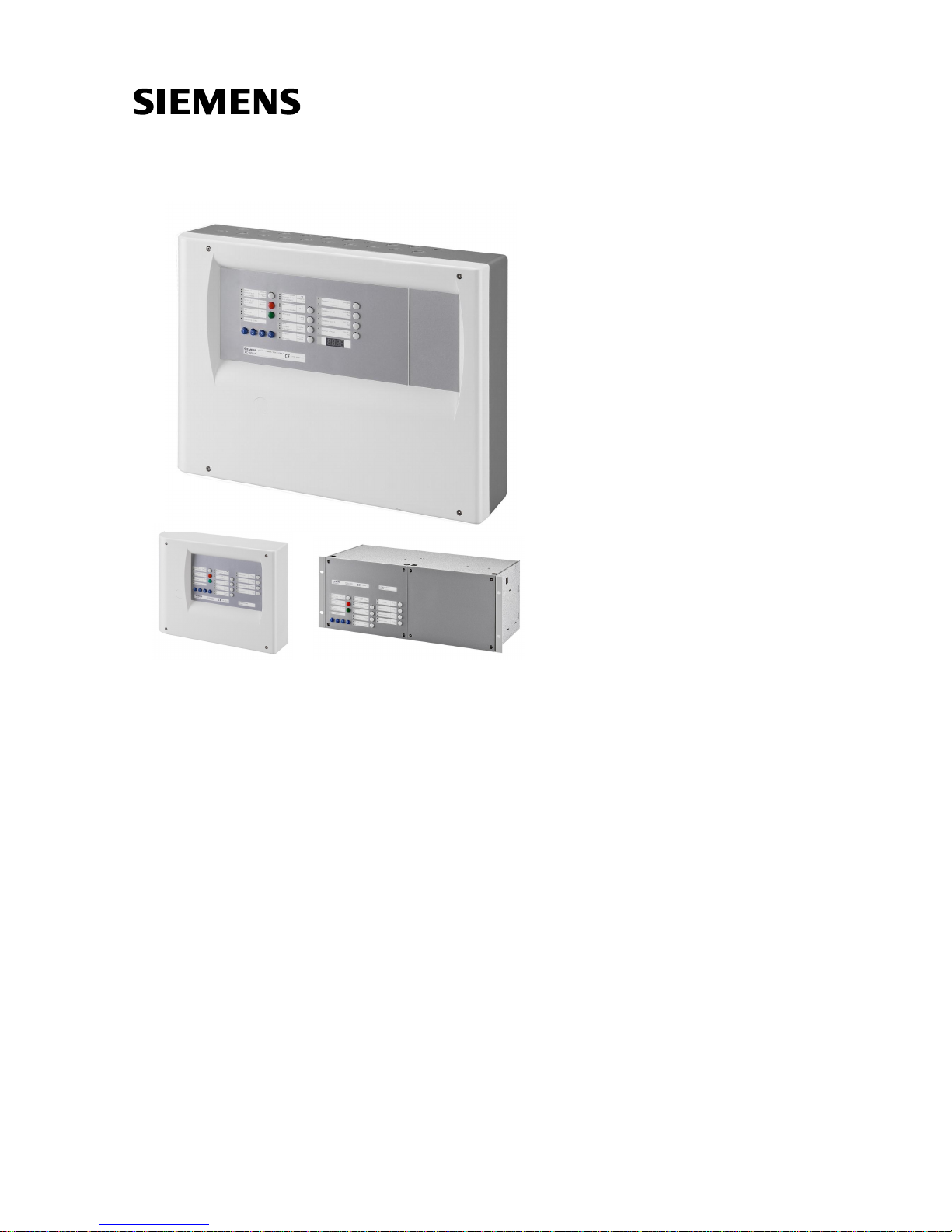
The equipment is declined in 3 versions:
- Wall mounting cabinet: XC1001-A / XC1005-A
- 19” rack cabinet: XC1003-A
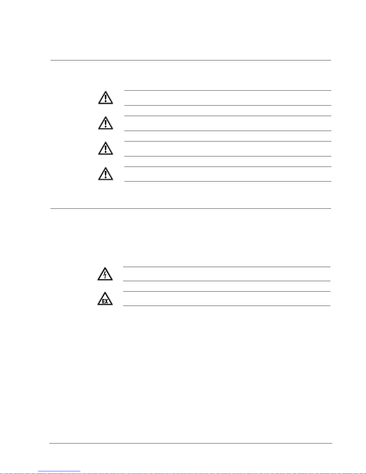
4.1 XC1001-A
System ON
Silence
buzzer
Silence
Re-sound
Sounders
Automatic blocked
Activated
Mode
Operating access
Earth fault
System fault
Disable
Fault
Manual blocked
Manual release
Released
Detector Zone 1
………………………………….
Mechanical blocked
Loss of agent
Incorrect status
Emergency
hold
Sounders
Fire controls
Enable
Disable
Detector test
Fire alarm
Remote ransmission
Disable
Test
Enable
Detector Zone 2
………………………………….
Detector Zone 3
………………………………….
432
1
2
Disable
Test
Enable
Disable
Test
Enable
Disable
Test
Enable
Power supply
Reset
RT-fault
RT-alarm
Actuators
Led test
Enable
Disable
Extinguishing contro l:
……………………………………… ……………..
s
XC1001-A
EN12094-1 Class A
EN54-4 / EN54-2
1116 - CPD– xxx
Fig. 1 XC1001-A
1 FCP1004-E power supply unit with charger
2 XCM1002 mainboard
3 4.5 A/h batteries
4 DIN rail for accessory mounting (Z3B171 relay module)
Page 13
Overview
13
Building Technologies A6V10257473_e_en_-Fire Safety 2015-03- 04
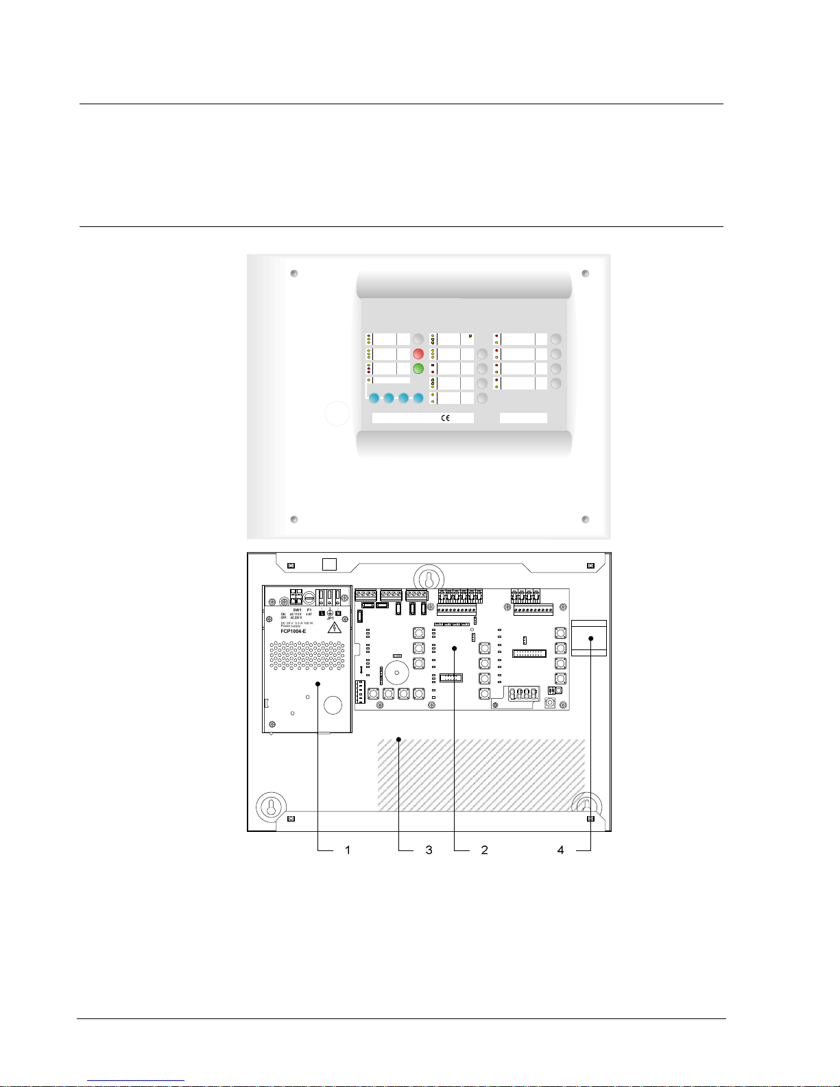
4.2 XC1005-A
Fig. 2 XC1005-A
1 FCP1004-E power supply unit with charger
2 XCM1002 mainboard
3 17 A/h batteries
4 DIN rail for accessory mounting (Z3B171 relay module)
5 FDCI / FDCI O222 module for the connection to a fire detection system
(option)
Page 14
Overview
14
Building Technologies A6V10257473_e_en_--
Fire Safety 2015-03- 04
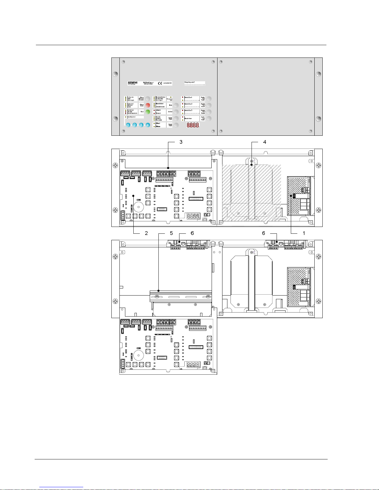
4.3 XC1003-A
Fig. 3 XC1003-A
1 FCP1004-E power supply unit with charger
2 XCM1002 mainboard
3 Removable mainboard holder
4 4.5 A/h or 7.2 A/h batteries
5 DIN rail f or accessory mounting (Z3B171 rel ay m odule, XCA1030 multi-sect or
modules, etc.)
6 FDCI / FDCI O222 module for the connection to a fire detection system
(option)
Page 15
Overview
15
Building Technologies A6V10257473_e_en_-Fire Safety 2015-03- 04
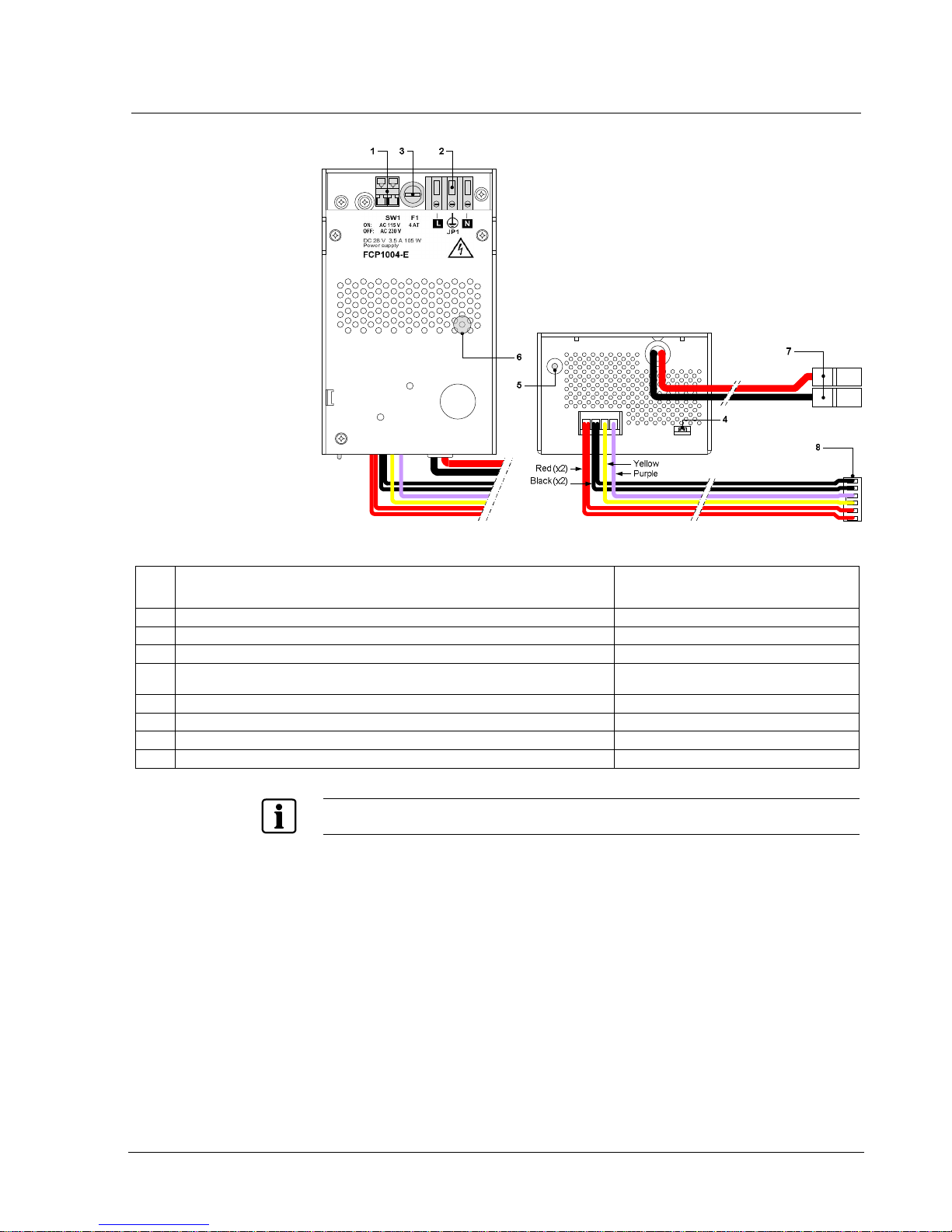
4.4 FCP1004-E
Fig. 4 FCP1004-E power suppl y unit
Mark Function Remarks
1 Mains voltage setting Shunt ON = 115VCA, shunt OFF = 230VCA
2 Mains terminal block
3 Mains fuse 4A / 250V
4 System start without mains power Shunt th e 2 terminals with a jum per and
remove after system start
5 Temperature sensor for battery charging voltage compensation Do not cover
6 Internal green LED «Mai ns operat ion» but visible fr om the f ront Not lit if no m ains volt age
7 Battery connection
8 XCM1002 main board connection
Security level of terminal blocks 1 and 2: Dangerous v oltage
Security level of other terminal blocks: SELV (Safety Extra Low Voltage)
Page 16
Overview
16
Building Technologies A6V10257473_e_en_--
Fire Safety 2015-03- 04
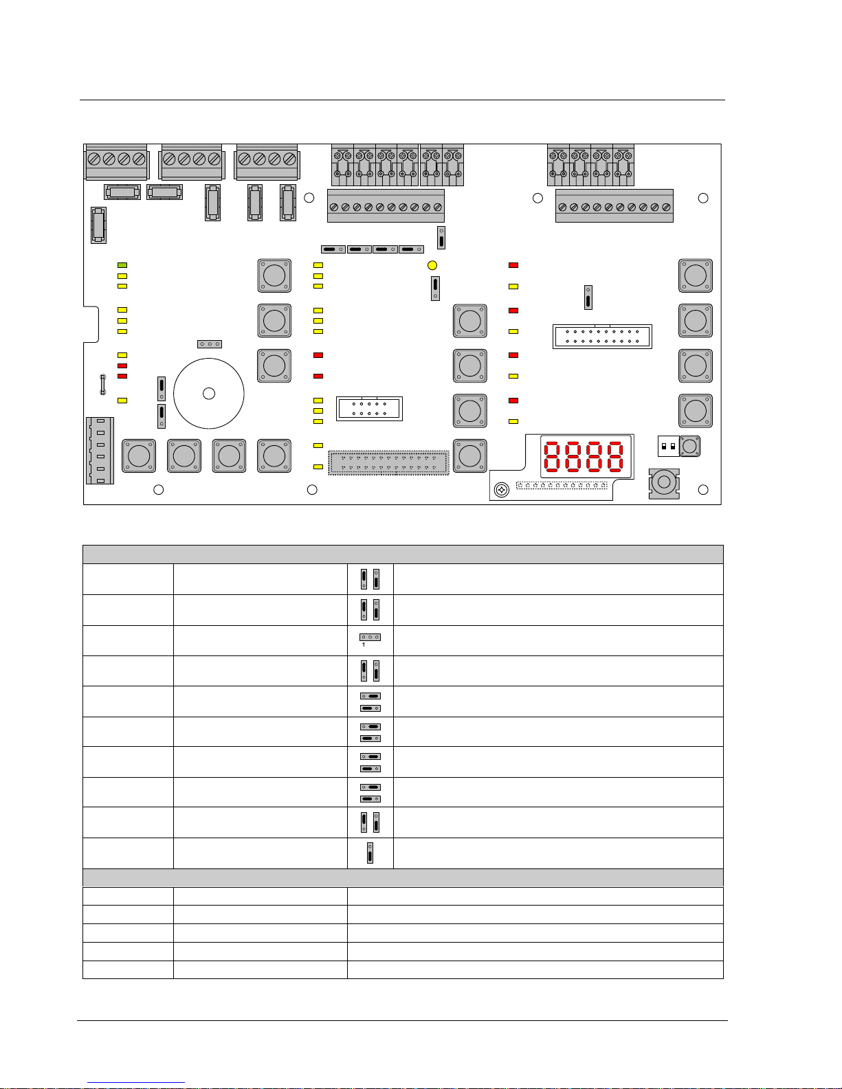
4.5 XCM1002
32
2411
12
13
14
15
16
17
18
19
20
21
22
23
25
26
27
28
29
30
31
10
7
1
2
3
5
6
8
9
4
X23
X24
ON
12
X8
X3X4
X28
X1
F3
F6 F5 F4
F2 F1
X14 X15 X16 X17
X13
X18
X26
S1
X21
1
X11
1
X12
X10X27 1X9
1
X7X6
11
X5 11
1
S18
X35
X20
41 2 3
5
6
7
8
9
10
11
12
13
14
15
1
Fig. 5 XCM1002 board
Setting el ements
X3 Internal buzzer En able/Disable Jumper up (factory setting) : bu zzer enabled
Jumper down : buzzer disabled (only for servicing)
X4 Type of pow er supply Jumper up (factory setting) : FCP100 4-E
Jumper down : do not use (for further use of extern al power supply)
X8 Operati ng access Level 2 Jumper on the left: Level 2 permanent access
1 – 2: external key switch (option)
X13 Relay contact typ e 1
(NO or NC)
Jumper up : NC contact
Jumper d own (factory setting) : NO contact
X14 Relay contact typ e 5
(NO or NC)
Jumper on the right : NC contact
Jumper on the left (factory setting) : NO contact
X15 Relay contact typ e 4
(NO or NC)
Jumper on the right : NC contact
Jumper on the left (factory setting) : NO contact
X16 Relay contact typ e 3
(NO or NC)
Jumper on the right : NC contact
Jumper on the left (factory setting) : NO contact
X17 Relay contact typ e 2
(NO or NC)
Jumper on the right : NC contact
Jumper on the left (factory setting) : NO contact
X18 Repeater (RTNet end of line
element)
Jumper up (factory setting) : EOL connected
Jumper down : do not use
X26 Serial connection (not used) Jumper down (factory setting) : do not change the position
Other elements
F1 / F2 Pluggable fuse 2 AF Fuse for protection of contr ol outputs 4 (F1) and 5 (F2)
F3 Pluggable fuse 1 AT Fuse for protection of 24V output
F4 / F5 / F6 Pluggable fuse 1 AT Fuse for pr otection of control outputs 1 (F4), 2 (F5) and 3 (F6)
S1 Reset —
S18-1 / S18-2 Not u sed Do not change (factory setting : OFF)
Page 17

Overview
17
Building Technologies A6V10257473_e_en_-Fire Safety 2015-03- 04
PCB terminal blocks
X1 Plug-in block 6 points
(1.5 mm2 max.)
1-2 (–) / 5 -6 ( +) 24V p ower s upply
3-4 (+) Power supply m onitoring
X5 Plug-in block 4 points
(2.5 mm2 max.)
1 (+) / 2 (–) Monitored output 5
3 (+) / 4 (–) 24V use output
X6 Plug-in block 4 points
(2.5 mm2 max.)
1 (+) / 2 (–) Monitored outp ut 3 (control polarities, reversed in st andby)
3 (+) / 4 (–) Monitored output 4
X7 Plug-in block 4 points
(2.5 mm2 max.)
1 (+) / 2 (–) Monitored outp ut 1 (control polarities, reversed in st andby)
3 (+) / 4 (–) Monitored outp ut 2 (control polarities, reversed in st andby)
X9 Plug-in block 8 points
(1.5 mm2 max.)
1 (+) / 2 (–) Monitored input 1
3 (+) / 4 (–) Monitored input 2
5 (+) / 6 (–) Monitored input 3
7 (+) / 8 (–) Monitored input 4
X10 Plu g-in block 8 p oints
(1.5 mm2 max.)
1 (+) / 2 (–) Fire d etectors zone 1
3 (+) / 4 (–) Fire d etectors zone 2
5 (+) / 6 (–) Fire d etectors zone 3
7 (+) / 8 (–) Extinguishing manual control
X11 Plu g-i n bl oc k 10 p oints
(1.5 mm2 max.)
1 / 2 Potential-free c ontact relay 1 (NO or NC)
3 / 4 Potential-free c ontact relay 2 (NO or NC)
5 / 6 Potential-free c ontact relay 3 (NO or NC)
7 / 8 Potential-free c ontact relay 4 (NO or NC)
9 / 10 Potential-fr ee c ontact rel ay 5 (NO or NC)
X12 Plu g-i n bl oc k 10 p oints
(1.5 mm2 max.)
1 … 8 (–) Logical outputs 1 t o 8
9 (–) / 10 (+) Repeater display / Repeater t er minal RTNet connection
X21 Jack 2.5 mm — Maintenance PC
X27 Plu g-in block 4 p oints
(1.5 mm2 max.)
1 (+) Reset
2 … 4 (+) Unmonitored inputs 2 to 4
X28 Faston 5.3 mm (+) To positive of battery (to provide “Total loss of power supply”
functi on (see note 1)
X20 (*) Flat cable 26 points — Connection for multi-sector module XC A1030
X35 Ter minal 12 p oints — Connection for 4 digits display
X23, 24 Not u sed — —
(*) on welding side
Note 1: T he XC10 provides th e EN5 4-2 option wit h req uir em en t 8.4 called “Tot al los s of pow er”. This opti on wh en s el ect ed acti v at es th e
system fault LED an d the buzzer continu ously, for at least 1 hour after a l ow discharg e battery disconnection. The option c an be
selected by wiring the +BAT terminal to the posit ive voltage of batteries (use of remainin g power aft er battery disconnection).
Page 18
Overview
18
Building Technologies A6V10257473_e_en_--
Fire Safety 2015-03- 04
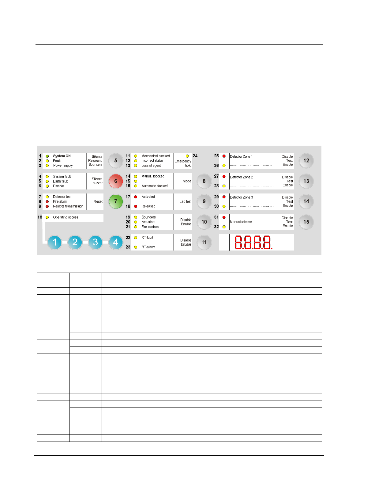
4.6 User interface
All display and control elements, except 4-digit display for XC1001-A version, are
accessible to the user:
- Led 1 to 32 indicators for operati ng conditi on,
- Keys 1 to 15 allowing :
è operating access
è operation (reset, off, test, etc)
è system test
è user functions programming
- 4-digit display showing:
è programming steps and opti ons
è pre-discharged warning time count down
è other information’s (calibration states, alarm counter, etc)
Fig. 6 XC100x-A, user interface
Indicators
State Description
N° Color
1 Green Fixed The control panel is in operation
2 Yellow Fixed The control panel is n ot able to function any more
Fast Fault on at least one component in the system (see paragraph 14.2 for t he detail)
Or,
Non-moni torred Control Input 3 is in active state, ass uming it is programmed as “External device fault”
(Step50 – O ption7)
3 Yellow Slow Mains fault
Fast Batteries fault
4 Yellow Fixed Microprocessor fault
Slow Jumper buzzer (X3 - XCM1002 board) not connected (remainder)
5 Yellow Fast At least on e compon ent connected to the c ontrol panel is grounded
6 Yellow Fixed – At leas t one component in th e system is disabled
– Calibrati on in progress or error
– Programmin g in progress
7 Yellow Slow At least one detection zone and/or extinguish ing manual control is being tested
8 Red Fixed At l eas t one detecti on zone is in alarm
9 Red Fixed Remote transmission activated (according to programming)
10 Yellow Fixed Level 2 oper ating access granted
Slow System test activated
11 Yellow Fixed Mechanical blocki ng device is in the bloc ked positi on
12 Yellow Fast – Mechanical blocki ng device is in a wrong posi tion
– Selector valve is in a wr ong position (used for multi-s ector appl ications)
13 Yellow Fast Loss of ag ent
Page 19

Overview
19
Building Technologies A6V10257473_e_en_-Fire Safety 2015-03- 04
Indicators
State Description
N° Color
14 Yellow Fixed – Manual release is block ed or being tested
15 Yellow Fixed – Standard = not used
– Alternati ve = automatic and manu al releas e grant ed (UK)
16 Yellow Fixed – Automatic release is blocked
– At least one detection zone which starts th e extinguis hing is off or being t ested
17 Red Fixed – All det ection zones which start the extinguishing are in alarm condition
– One of the el ectrical man ual trigg ering devic e (DM1103-L) is actuated
Fast One of the d etection zones which start the extinguishing is in alarm c ondition
18 Red Fixed Extin guishing agent is rel eased
Slow / Fas t Discharged contact is not activat ed within 30 seconds af ter actu ators c ontrol (according to programming)
19 Yellow Fixed Sounders are disabled
Slow Sounders test is in progress (real activation)
Fast At least, an output programmed as Sounders is in fault condition (break or short-circuit)
20 Yellow Fixed Actuators are disabl ed
Slow Actuators test is in progress (simulated activation)
Fast – At least, one output programmed as ac tuators is in fault condition (br eak or short-c ircuit)
– Calibration in progr ess or error or no calibration data
21 Yellow Fixed Fire contr ols are disabled
Slow W arning panels tes t is in progr ess ( real activation)
Fast At least, one output programmed as fire controls is in fault condition (break or short-circuit)
22 Yellow Fixed R T-fault is disabled
Slow RT-f ault test is in progress (real activation)
23 Yellow Fixed R T-alarm is disabl ed
Slow RT-alarm test is in progress (real activ ation)
Fast At least, one output pr ogrammed as RT-alarm is in fault condition (break or short-c ircuit)
24 Yellow Fixed Emergenc y abort is activated
Slow Emergency hold is activat ed (DM1103-S)
Fast At least, one input pr ogrammed as emergency hold/ab ort is in fault condition (break or short-circ uit)
25 Red Fixed Detection zone 1 is in alarm condition
Slow Detection zone 1 is in alarm condition (first alarm)
26 Yellow Fixed / Slow Detection zone 1 is disabled (fixed) / being tested (slow)
Fast Detection zone 1 is in fault cond ition (break or short-circuit)
27 Red Fixed Detection zone 2 is in alarm condition
Slow Detection zone 2 is in alarm condition (first alarm)
28 Yellow Fixed / Slow Detection zone 2 is disabled (fixed) / being tested (slow)
Fast Detection zone 2 is in fault cond ition (break or short-circuit)
29 Red Fixed Detection zone 3 is in alarm condition
Slow Detection zone 3 is in alarm condition (first alarm)
30 Yellow Fixed / Slow Detection zone 3 is disabled (fixed) / being tested (slow)
Fast Detection zone 3 is in fault cond ition (break or short-circuit)
31 Red Fixed Manual releas e is activ ated (DM1103-L lin e)
Slow Manual release is activat ed (DM1103-L line) – F irst alarm
32 Yellow Fixed / Slow Manual release is disabled (fixed) / being tested (slow)
Fast Manual release is in fault condition (break or short-circuit)
Page 20

Features
20
Building Technologies A6V10257473_e_en_--
Fire Safety 2015-03- 04
Keys Description
1 … 4 Operating access code input (level 2, progr amming, system test, etc.)
è W hen op erating access level 2 is selec ted, if the code is ent er ed again, t he system returns t o the level 1, wi thout waiting
for the end of the 4 minutes timeout
5
Silence / Restar
t sounders by successive pressing:
– 1st pressing: silence sounders
– 2nd p ressing: restart sounders etc…
è Operating acc ess level r equired f or this operation = level 2 (silenc e sounders is not possible during pre-dis charged
warning time)
6
Silence buzzer
è Operating access level required for this operation = l evel 1 or 2 or 2 o nly (according to prog ramming)
è If a Repeater Ter minal is connected to the XC10, and if option 61 step 02 is selected, silenc e buzzer on XC10 silences
also buz z er on repeater
7
1)
Reset
of the syst em. Reset is not possible
:
– during pre-discharged warning time, emergency stop and flooding time
– if buzzer and/or sounders are not silenced
– if manual release button and/or discharged contact ar e not reset (accord ing to pr ogramming)
è Operating acc ess level required f or this operati on = level 2
2) Fault reset
è Op er ating acc ess level required f or this operati on = level 2
8
Mode of operating, by successive press ing:
– 1st pressing: automatic blocked
– 2nd pr essing: automatic and manual blocked
– 3rd pressing: normal mode
è Operating access level required for these operations = level 2
9
Led and buzzer test (duration = 6 seconds)
:
All led indicators are activated and the buzzer sounds continuously (during the first three seconds, all the s egments of t he
display are activat ed, then th e SW version is displ ayed)
è Operating acc ess level required f or this operati on = level 1
10
Disable / Enable by successive pres sing:
– 1st pressing: actuators are disabled
– 2nd pr essing: s ounders an d actuat ors ar e disabl ed
– 3rd pressing: fire controls are disabled
– 4th pressing: all is disabled
– 5th pressing: all is enabled
è Operating access level required for these operations = level 2
11
Disable / Enable by successive pres sing:
– 1st pressing: RT-fault is disabled
– 2nd pressin g: RT-fault is en abled / RT -alarm is d isabled
– 3rd pressing: RT-fault and RT -alarm are disabled
– 4th pressing: all are enabled
è Operating access level required for these operations = level 2
12
Disable / Enable by successive pressing (n ot possible in case of fault or
alarm):
– 1st pressing: zone 1 is disabled
– 2nd pr essin g: z one 1 is tested
– 3rd pr essing: zone 1 is in norm al conditi on
è Operating access level required for these operations = level 2
13
Disable / Enable by successive pressing (n ot possible in case of fault o
r alarm):
– 1st pressing: zone 2 is disabled
– 2nd pr essin g: z one 2 is tested
– 3rd pr essing: zone 2 is in norm al conditi on
è Operating access level required for these operations = level 2
14
Disable / Enable b y successive pressing (n ot possible in case of fault
or alarm):
– 1st pressing: zone 3 is disabled
– 2nd pr essin g: z one 3 is tested
– 3rd pr essing: zone 3 is in norm al conditi on
è Operating access level required for these operations = level 2
15
Disable / Enable b y successive pressing (n ot possible in case of fault
or alarm):
– 1st pressing: manual release is disabled
– 2nd pr essin g: m anual rel ease is t ested
– 3rd pr essing: manual release is in normal conditi on
è Operating access level required for these operations = level 2
Page 21

Features
21
Building Technologies A6V10257473_e_en_-Fire Safety 2015-03- 04
5 Features
Power supply (FCP1004-E) Primary source (mains)
Voltage
Current
Power
115 / 230 VCA +10 …-15% – 50 / 60 Hz
1.75 A max.
150 VA max.
Secondary source (batteries)
Connect a bl e batter ies
Voltage
Charging current max.
Internal resistance max.
Deep discharge (disconnection threshold)
2 x 12 V / 4.5 … 17 Ah
23.4 … 27.6 V
1.3 A (with temperature compensation)
1 Ω
20 V +/-3%
Output
Voltage
Max. avai lable current
Min. current
Power
Switching frequency / Ripple
27.3 V +/- 0.3 V (25°C)
Imax a : 2 A (b atteries load ing)
Imax b : 3.5 A (batteries loaded)
0.05 A
105 W max.
132kHz / 7 0 mVpp max.
XCM1002 Input voltag e
Current consumption
I/Os s ecurity level
22.5 … 27.6 V (25°C)
190 mA max. without prim ary source
SELV (Safety Extra Low Voltage)
Detection lines Type / number of detectors
Compatible detectors
End of line element (EOL)
Standby condition voltage / current
Alarm condition voltage / current
Line resistance
Collective / 32 max. (according to detector t ype)
Siemens (Algorex, Sinteso, Synova, Cerberus FD110
series)
Transzorb 18 V (P6KE18CA)
17.1 … 19.3 V (fixed by EOL) / 11 mA max.
5.5 … 16.5 V / 11 … 57.1 mA max.
80 Ω max.
Manual release line Type / number of manual actuators
End of line element (EOL)
Voltage / standby line current
Voltage / al ar m line curr ent
Line resistance
DM1103-L / 32 max.
Transzorb 18 V (P6KE18CA)
17.1 … 19.3 V (fixed by EOL) / 11 mA max.
5.5 … 16.5 V / 11 … 57.1 mA max.
80 Ω max.
Monitored inputs 4
Activation resistance
End of line element (EOL)
Line resistance
680 Ω or 1.2 kΩ
3.3 kΩ r esistance
80 Ω max.
Control inputs (non
monitored)
4 Activation +24 V, via contact
Monitored co ntrol outputs
Outputs 1 to 3
Outputs 1 to 3
Control voltage / current
End of lin e element
24 V / 1 A max.
3.3 kΩ r esistance
Outputs 4 and 5
Control voltage / current
End of lin e element
24 V / 2 A max.
No EOL (line calibration)
Driver outputs 8 (programmable) 24 V / 40 mA max.
Relay outputs (contacts) 5 (4 programmable) 30 V / 1 A max. / NO or NC
Connection s XCM1002
Inputs - outputs type / section Plug-in screw t er minal bloc ks
2.5 mm2 max. (X5, X5, X7)
1.5 mm2 max. (all oth ers )
FCP1004-E
mains input type / section Plug-in screw termi nal block / 2.5 mm2 max.
Environmental conditions Operating / Storage temperature
Humidit y relative at 40± 2° C
-5 ... +40° C / -20 ... +60° C
93% max., without condens ation
Mechanical data XC1001-A Cabinet / Protection index
Color
Dimensions (l x h x p) / Weight
Metal frame with plastic cover / IP30
RAL9003 (cover), RAL9006 (user interface)
370 x 286 x 90 mm / 4.1 kg
XC1005-A Cabinet / Protection index
Color
Dimensions (l x h x p) / Weight
Metal case with plastic cover / IP40
RAL9003 (cover), RAL9006 (user interface)
505 / 375 / 125 m m / 6.5 kg
XC1003-A Cabinet / Protection index
Color
Dimensions (l x h x p) / Weight
Rack 19’’ 4U / IP30
RAL9006
482.6 (19’’) x 177.8 (4U) x 187 mm / 6 .6 kg
Conformity EN 12094-1, EN 54-2/A1, EN 54-4/A2 —
Page 22
Installation
22
Building Technologies A6V10257473_e_en_--
Fire Safety 2015-03- 04
6 Installation
Generally, the XC10 must be easily accessible and i nstalled:
- outside the protected area
- protected from mechanical shocks and bad weather
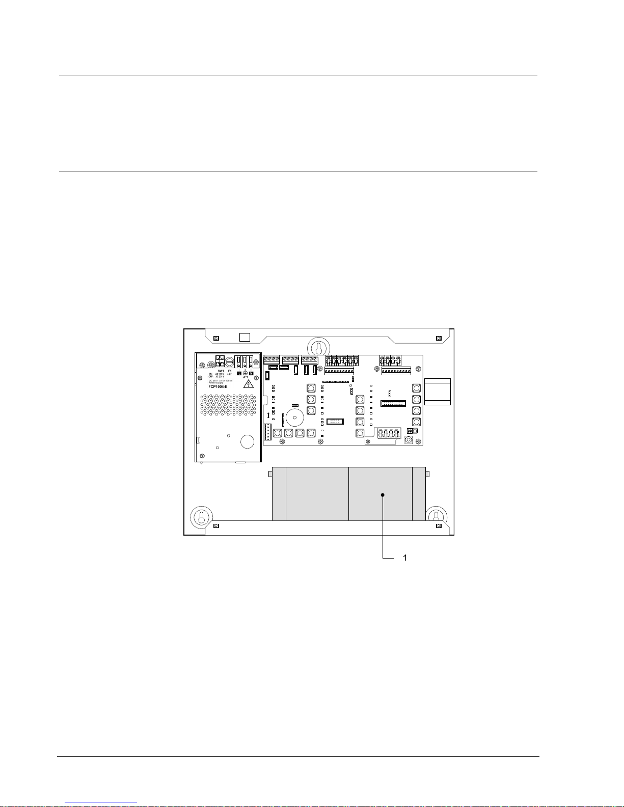
6.1 XC1001-A / XC1005-A
The XC10 must be installed on a fixed and stable support, with a height ranging
between 1.60 m and 1.70 m (eliminate the irregularities from the mounting surface
≥ 5 mm).
1. Remove the front cover
2. Mark and drill the mounting holes using the drilling template provided (start with
the hole for the top central screw)
3. Fix the chassis using 3 screws Ø 4 x 50 mm (not provided)
4. Cut out the cable entries
5. Cut out the plastic housing according to the cable inputs (XC1001-A)
6. Mount the cable glands if necessary (required for protection rating IP30)
7. Install the batteries and fix the bat tery holders
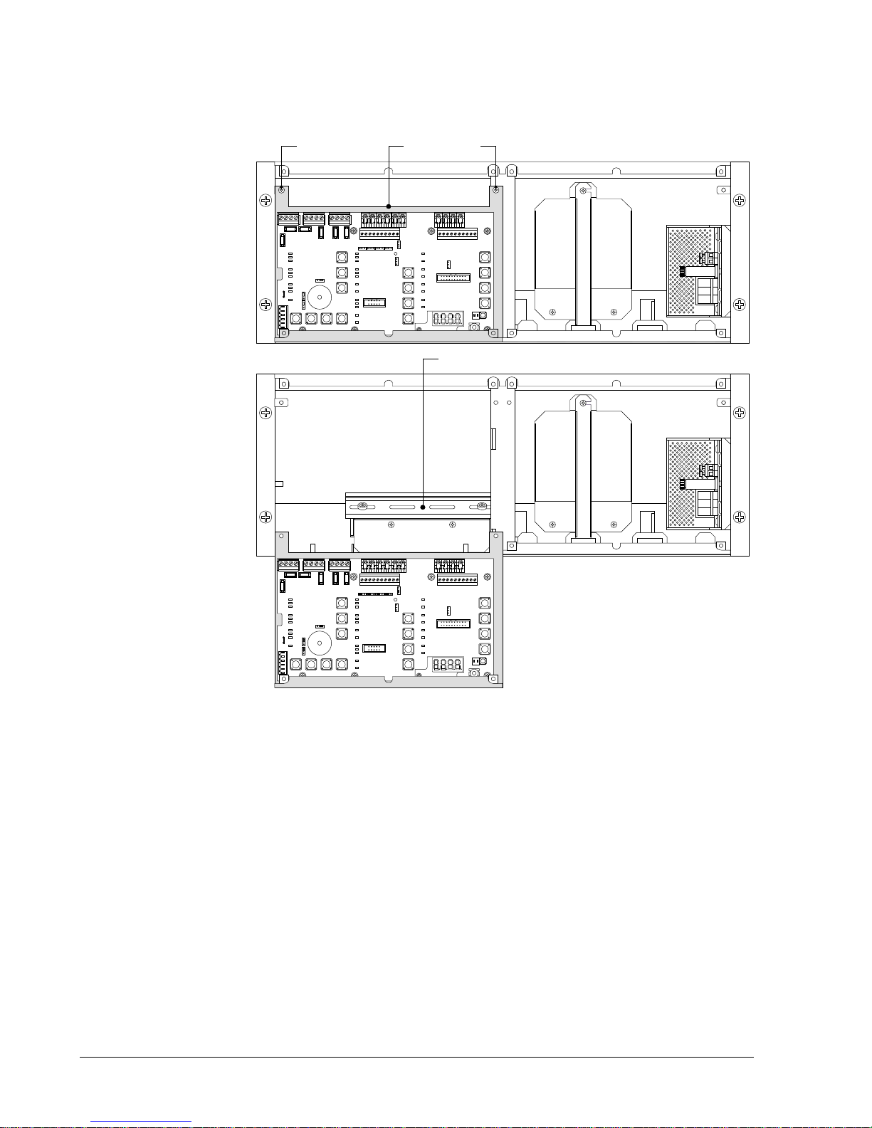
1 12 V – 4.5 Ah batteries
Fig. 7 XC1001-A, bat tery installation
Page 23
Installation
23
Building Technologies A6V10257473_e_en_-Fire Safety 2015-03- 04
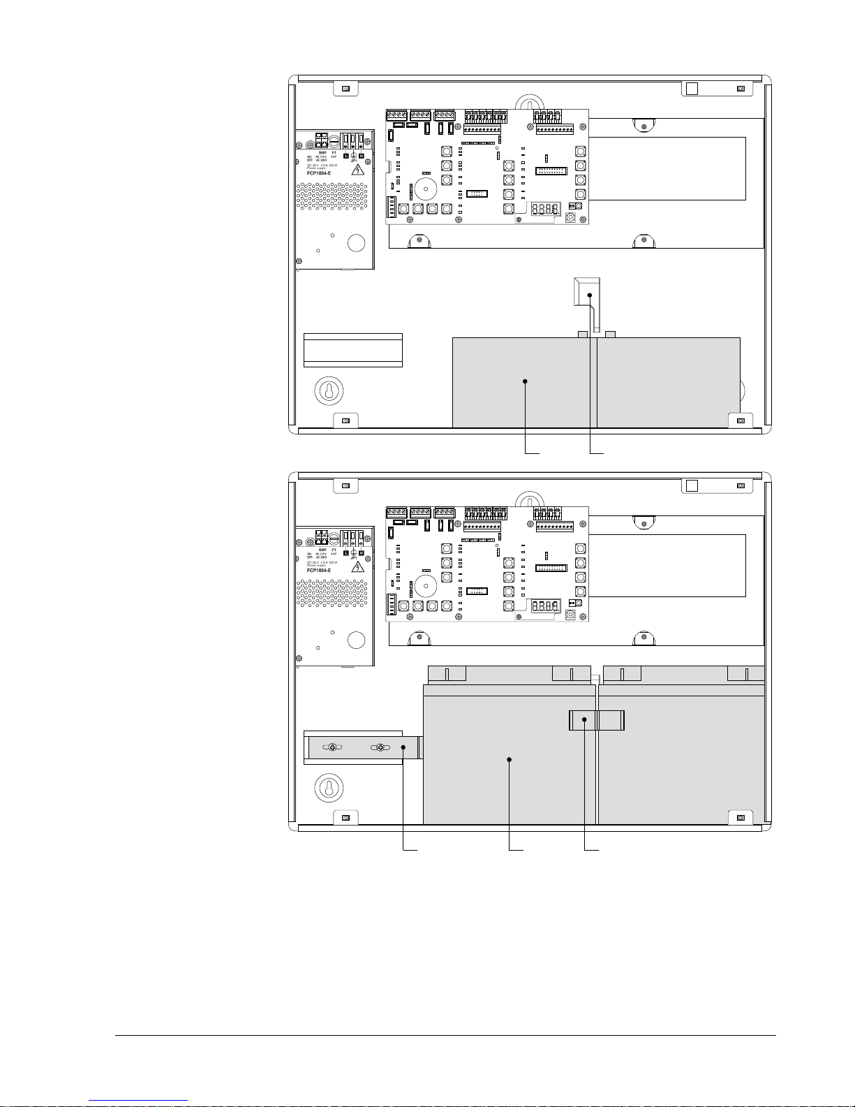
ON
12
1 4
ON
12
23 3(insert in slot 4)
1 12 V – 12 Ah batteries
2 12 V – 17 Ah batteries
3 FCA1014 battery holder (option)
4 Slot for battery holder
Fig. 8 XC1005-A, bat tery installation
Page 24
Installation
24
Building Technologies A6V10257473_e_en_--
Fire Safety 2015-03- 04
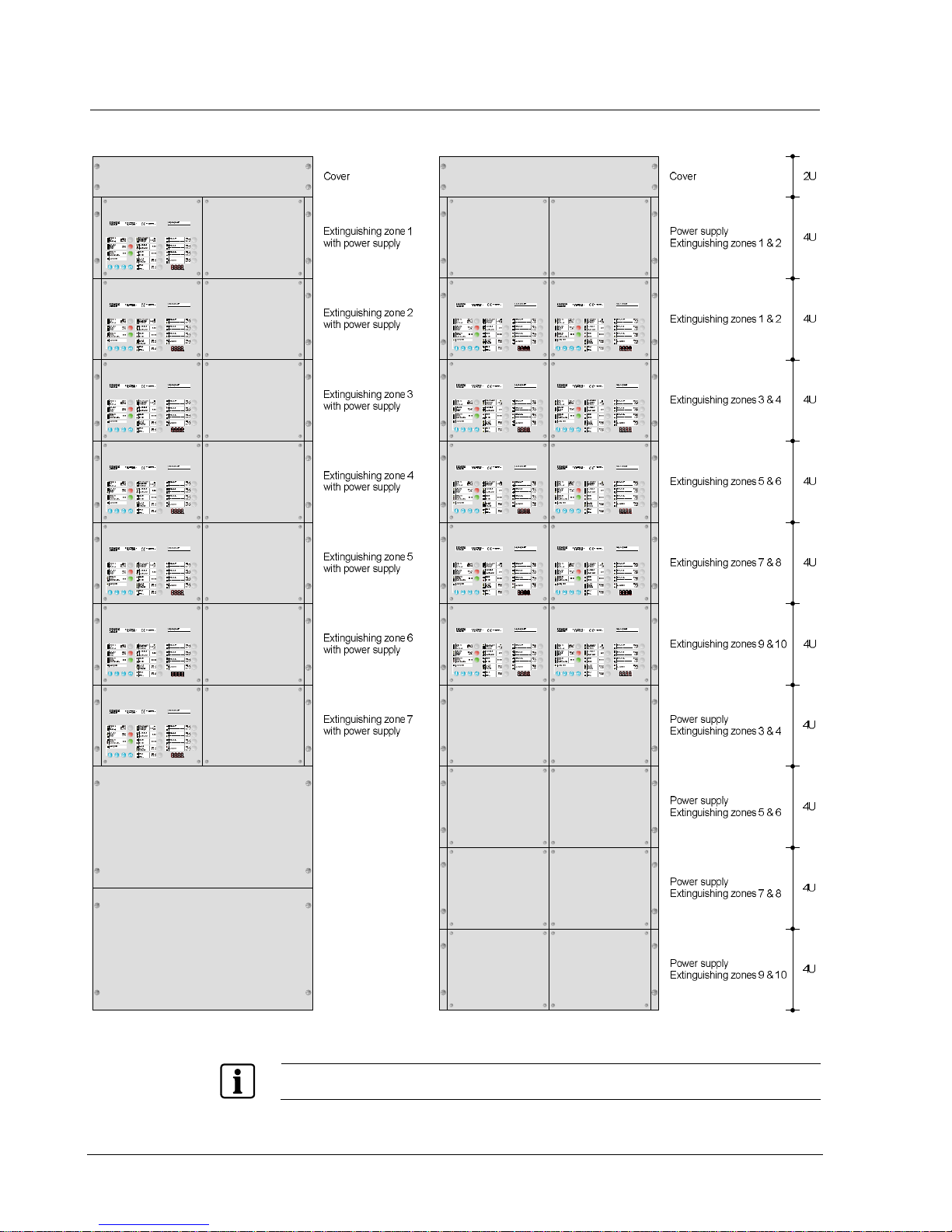
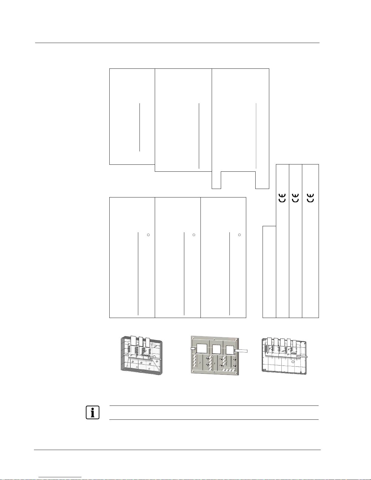
6.2 XC1003-A
Fix the XC1003-A into a 19'' housing cabinet with a protecti on rating IP ≥ 30.
Fig. 9 XC1003-A, mounting examples
The interval between 2 extinguishing racks and there power su pply rack should n ot exceed 12U.
Page 25
Installation
25
Building Technologies A6V10257473_e_en_-Fire Safety 2015-03- 04
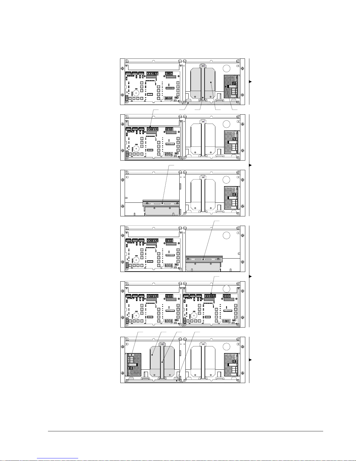
XC1003-A, mounting adaptation
The 19” rack is symmetrical . This allows, with some mounting/ unm ounting
operations, to adapt it to various configurations (2 racks minimum are necessary).
A
B
B
A
B
Remove parts 5 & 6
from rack B
Reassemble parts 1, 2, 3 & 4 from
rack A in rack B
2 31 4
6
6
Remove parts 1, 2, 3 & 4
from rack A
A
Reassemble parts 5 & 6 from
rack B in rack A
1234
ON
12
ON
12
5
ON
12
ON
12
ON
12
5
Fig. 10 XC1003-A, mounting adaptation
Page 26
Installation
26
Building Technologies A6V10257473_e_en_--
Fire Safety 2015-03- 04
XC1003-A, commissioning / connection / maintenance
The removable board hol der (1) can be positioned, after screw unmounting (3), as
indicated bel ow to reach the DIN rail (2).
ON
12
ON
12
13 3
2
Fig. 11 XC1003-A, removable stand in “Commissioning” position
Page 27
Installation
27
Building Technologies A6V10257473_e_en_-Fire Safety 2015-03- 04
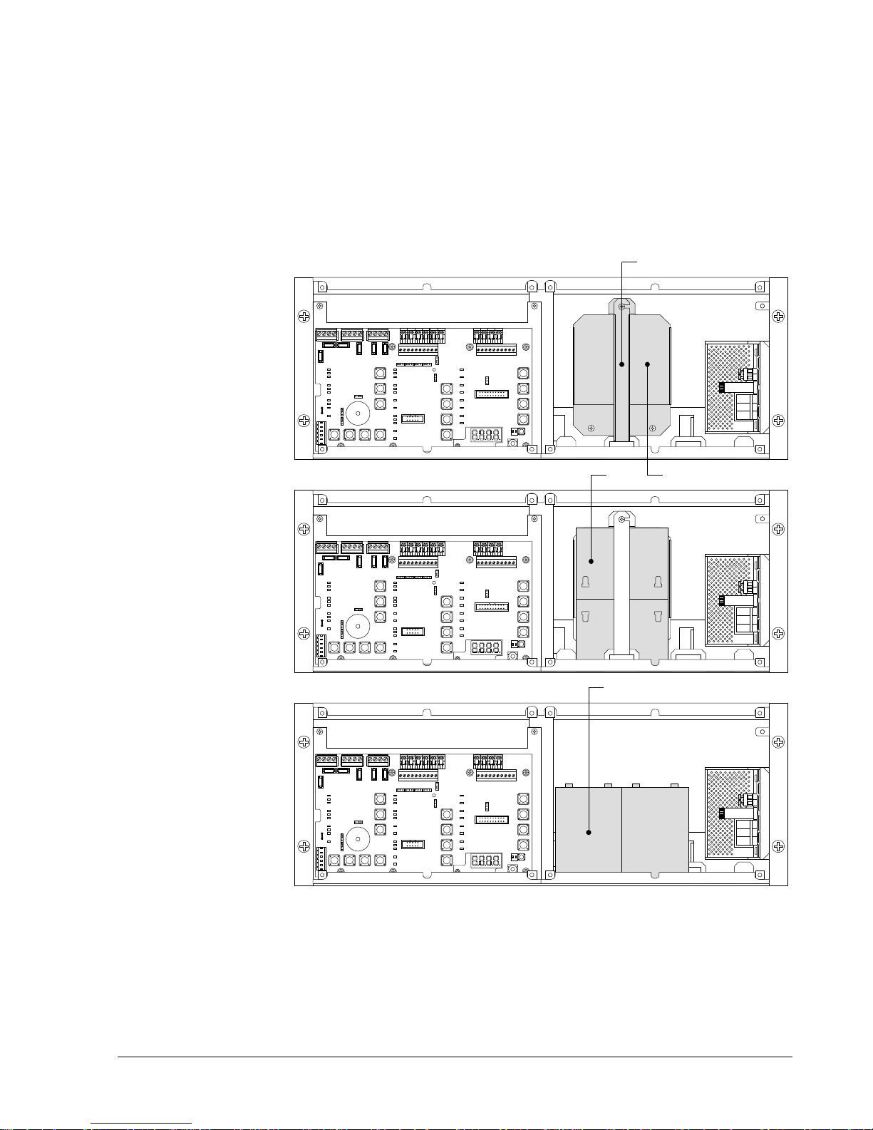
XC1003-A, batteries installation
4.5 Ah batteries:
1. Remove the holder (1)
2. Install the batter ies (3) as shown below
3. Remount the holder (1)
7.2 Ah batteries:
1. Remove the parts (1) and (2)
2. Install the batter ies (4) as shown below
ON
12
ON
12
2
ON
12
1
3
4
Fig. 12 XC1003-A, battery installation
Page 28
Installation
28
Building Technologies A6V10257473_e_en_--
Fire Safety 2015-03- 04
6.3 User interface labels
Insert the l abels f ollowing the instructions on the board provided with the
equipment.
XC1001-A
XC1003-A
XC1005-A
Stripe EN
A5Q00034729A-03
Pos. 2
Mechanical blocked
Incorrect status
Mode
Manual blocked
Loss of agent
Automatic blocked
Led test
Activated
Released
Sounders
Actuators
Fire controls
RT-fault
RT-alarm
Emergency
hold/abort
Pos.2
Mechanical blocked
Incorrect status
Mode
Manual blocked
Loss of agent
Automatic blocked
Led test
Activated
Released
Sounders
Actuators
Fire controls
Disable
Enable
RT-fault
RT-alarm
Emergency
abort
Disable
Enable
Disable
Enable
Disable
Enable
Pos. 2
Mechanical blocked
Incorrect status
Mode
Manual blocked
Loss of agent
Automatic blocked
Led test
Activated
Released
Sounders
Actuators
Fire controls
RT-fault
RT-alarm
Emergency
hold
Disable
Enable
Disable
Enable
Pos. 1
System ON
Fault
Silence
buzzer
System fault
Power supply
Disable
Reset
Detector test
Remote transmission
Operati ng access
Earth fault
Silence
Re-sound
Sounders
Fire alarm
Pos.3
Disable
Test
Enable
Detector Zone 1
…………………………………….
Detector Zone 2
…………………………………….
Detector Zone 3
…………………………………….
Manual release
Disable
Test
Enable
Disable
Test
Enable
Disable
Test
Enable
Pos.7
Disable
Test
Enable
Disable
Test
Enable
Disable
Test
Enable
Disable
Test
Enable
Detector Zone 1
…………………………………….
Detector Zone 2
…………………………………….
Detector Zone 3
…………………………………….
Manual release
Pos. 5
Extinguishing control
…………………………………….
EN12094-1 Classe A
EN54-4 / EN54-2
1116 - CPD – xxx
Pos. 4
s
XC1001-A
EN12094-1 Classe A
EN54-4 / EN54-2
1116 - CPD – xxx
Pos. 8
s
XC1003-A
1116 - CPD – xxx
s
XC1005-A
EN12094-1 Classe A / EN54-4 / EN54-2
…………………………………...
Pos. 6
XC1005-A
Pos.6
Pos.7
Pos.2
Pos.1
XC1001-A
Pos.4
Pos.5
+0,15
0.0
0
1
3
Pos.3
Pos.2
Pos.1
XC1003 -A
Pos.5
Pos.3
Pos.2
Pos.1
Pos.8
Fig. 13 XC100x-A, user interface labels
The label to be inserted in position 2 is different whether the stop/emergency hold function is used or
not.
Page 29
Connections
29
Building Technologies A6V10257473_e_en_-Fire Safety 2015-03- 04
7 Connections
The installation must be realised by qualified personnel and in conformity with the
applicable nati onal electric standard.
7.1 Mains
Connection with the mains must be established through an external circuit breaker
(bipolar circuit breaker 1 A).
3. Make sure that the mains voltage is switched off
4. Connect the mains cabl e to the PSU terminals according to the pi n assignment
specified onto the PSU:
– Protection ground ( ), neutral (N) and phase (L)
5. Fix the cable with two fasteners and check, during installation, that these fixings
are well in place
The XC100x-A equipment is not designed to be c onnected according to an IT earth network .
If such a network must be us ed, a separation transformer will have to be installed.
Danger - Electrical v oltage
Mortal danger due to electric shock
- B ef ore layi n g th e mai ns c abl e, m ak e sur e that it is n ot c on n ect ed t o th e pow er s up pl y.
- Ch eck to mak e sur e that the m ains are secured agai ns t inad ver t ent l y being s witc h ed on.
Danger - Short circuit
Potential damage to hardware
- B ef or e inst al li ng or dismantl in g the power supply unit, rem ov e t h e wir e jum p er between th e two
batteries.
- T his ensu res that th e sec on d ary side is current-fr ee and that no mod ules can be dam ag ed due to
a short circuit.
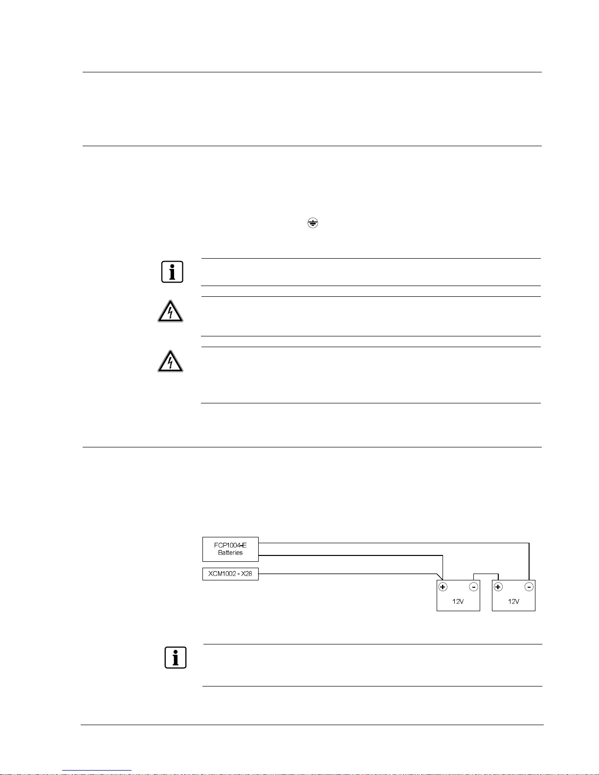
7.2 Batteries
Two 12 V batteries, connected in series, can be connected with t he FCP1004- E
power supply. According to the control units, the following batteries can be
installed:
- XC1001-A : 4.5 Ah
- XC1005-A : 4.5 Ah, 7.2 Ah, 12 Ah or 17 Ah
- XC1003-A : 4.5 Ah or 7.2 Ah
Fig. 14 Battery connection
In some countri es i.e. [ FR], it is r equired to indicate the total loss of power suppl y (opti on with
requirement EN54-2). In such case, connect the wire pr ovided between + of th e batteries and the X28
termin al of XC M1 0 02 m ai nboard.
If this option is not required in your country, do not connect the wire from +b atteries to X28
Page 30

Connections
30
Building Technologies A6V10257473_e_en_--
Fire Safety 2015-03- 04
7.2.1 Battery capacity calculation
Battery capacity must be calculated according to the following formula:
K
Batt
= ((I
R total
* tR) + (I
A total
* tA)) * K
dis
* K
age
K
Batt
: battery capacity (Ah)
I
R total
: operating curr ent , internal and ext ernal in standby condition (A)
I
A total
: operati ng curr ent , internal and external in alarm condition (A)
tR: required backup time in standby condition (hours)
tA: required backup time in alarm condition (hours)
K
dis
: = 1.1 drops i n capacity, applicable only for 12 hours backup time or less
K
age
: = 1.25 safety factor, applicable only for 24 hours backup time or less
To define the operating current, all internal and external devices connected to the
XC10 shall be taken into account:
- all components installed inside the XC100x-A are consi dered as internal
devices, i.e. : XCA1030, XCA1031, relay modules, etc.
- al l components installed outside the XC100x-A are considered as external
devices, i.e.: actuator, sounders, warning panels, repeater terminals (when
supplied by the XC10), etc.
Components
Current consumption (A) / 24 VDC
Standby conditi on
Alarm condition
XCM1002 0.168 0.247
Actuator 0 See component datasheet
Warning panel 0 See component datasheet
Sounder 0 See component datasheet
Fire controls 0 See c om ponent datasheet
XT1001-A1 powered by XC10 0.012 0.020
XCA1031 0.114 0. 141
Single-sector installation example:
– 2 actuators (POUSSAX24) activ ated during 10 seconds (360mA each)
– 6 warning panels (70mA each)
– 10 sounders (20mA each)
– 2 repeaters XT1001-A1 powered by XC10
Battery capacity calculation for 12, 24 and 72 hours backup time, followed by an
alarm conditi on during 15 mn:
è I
R total
= 0.168 + (0.012 x 2) = 0.192 A
è I
A total
= 0.247 + (0.020 x 2) + ((0.360 x 2) x (10 / (15 x 60))) + (0.070 x 6) +
(0.020 x 10) = 0.915 A
è 12 hours : K
Batt
= ((0.192 x 12) + (0.915 x 0.25)) x 1.1 x 1.25 = 3.48 Ah
è 24 hours : K
Batt
= ((0.192 x 24) + (0.915 x 0.25)) x 1.25 = 6.04 Ah
è 72 hours : K
Batt
= ((0.192 x 72) + (0.91 x 0.25)) = 14.05 Ah
Multi-sector installation example:
– 4 solenoid valves (DEMAFM or DEMADE M) activated during 10 seconds
(400mA each)
– 1 actuator POUSSAX24 connected to XCA1031
– 12 warning panels (70mA each)
– 10 sounders (20mA each)
Page 31

Connections
31
Building Technologies A6V10257473_e_en_-Fire Safety 2015-03- 04
– 2 fire controls, solenoid 3 W à door contact for ex.(125mA each)
– 2 repeaters XT1001-A1 powered by XC10
Battery capacity calculation for 12, 24 and 72 hours backup time, followed by an
alarm conditi on during 15 mn:
è I
R total
= 0.168 + 0.114 + (0. 012 x 2) = 0.306 A
è I
A total
= 0.247 + 0.141 + ((0.400 x 4) * ( 10 / (15 x 60))) + 0.360 + (0.070 x 12) +
(0.020 x 10) + (0.125 x 2) + (0.020 x 2) = 2.095 A
è 12 hours : K
Batt
= ((0.306 x 12) + (2.095 x 0.25)) x 1.1 x 1.25 = 5.77 Ah
è 24 hours : K
Batt
= ((0.306 x 24) + (2.095 x 0.25)) x 1.25 = 9.83 Ah
è 72 hours : K
Batt
= ((0.306 x 72) + (2.095 x 0.25)) = 22.55 Ah à not possible with
the XC10 power supply
Install ed batteri es shall have a capacity > K
Batt
calculated
7.3 Fire detectors/Manual release control buttons
7.3.1 Standard wiring
Four monitored inputs are available on the X10 terminal block for the connection of
fire detectors or alarm contact (i.e. contact from FDCIO222) and electrical manual
triggering devices (DM1103-L)
- Detection zones 1 to 3 operation is defined at programming steps 52 to 55 (see
paragraph 12.14)
- Ex tinguishing manual release control operation is defi ned at programming step
65 (see paragraph 12.21). Up to 32 buttons DM1103-L can be connected
Technical data common to the 4 inputs
EOL: transzorb 18V connected at the end of the line
Line resistance max.: 80 Ω
Page 32

Connections
32
Building Technologies A6V10257473_e_en_--
Fire Safety 2015-03- 04
Fig. 15 XC100x-A, connec tion of detect ors and manual triggering devices
The number of detectors which can be connected is determi ned by dividing the
collective system line connection factor (KLK = 32) by the collective element load
factor (KMK = see table bel ow).
Series of detectors Designation KMK Nb
ALGOREX DO1101A / DO1102A / DO1104A 1 32
DT1101A / DT1102A 1 32
DF1191 / DF1192 6 5
SINTESO FDOOT241-9 / FDOOT241-A9 2 … 1.25 (*) 16 … 25
FDF221- 9 / FDF241-9 5 6
FDL241-9 10 3
SYNOVA OP320C / OH320C 1 32
HI320C / HI322C 1 32
CERBERUS FD110 series OH110, OP110, HI110, HI112 1 32
(*) Depen ds on detector index and set of parameters
For Sinteso and C er berus FD110 series detectors, select an appropr iate set of parameters.
Page 33

Connections
33
Building Technologies A6V10257473_e_en_-Fire Safety 2015-03- 04
7.3.2 Wiring for explosion hazard areas
Fig. 16 Wiring for explosion hazard areas
In ex-areas, use only fire detectors that are approved for ex-areas. Between the
explosion-hazard ar ea and the non-ex-area, the detector line must be galvanically
insulated (DC1192) and laid via a safety barrier (SB3). The termination elem ent
EOL22Ex must be provided as line terminator.
Country-specif ic regulations always apply to installation in ex-areas.
The following document provides further informations:
Fire alarm signal in areas at risk of explosion - Principles, applications, instal lation,
maintenance (001204).
7.4 Monitored inputs
Four monitored inputs are available on X9 terminal block for the connection of
various devices. Operation is defined at programming steps 28 to 31 (see
paragraph 12.9).
Technical data common to the 4 inputs
EOL: 3.3 kΩ resistance connected at the end of the line
Line resistance max.: 80 Ω
Page 34

Connections
34
Building Technologies A6V10257473_e_en_--
Fire Safety 2015-03- 04
7.4.1 Monitored input 1
This input is exclusively reserved for the connection of the extinguishing
discharged contact. Operation is defined at programming step 28.
Fig. 17 XC100x-A, monitored input 1 connection
1 Discharged contact normally closed (NC)
2 Discharged contact normally open (NO)
3 No contact connected (3.3kΩ EOL is not required)
7.4.2 Monitored input 2
This input is exclusively reserved for the connection of the loss of agent devices
(manometer or weighing device). Operati on i s defined at programming step 29.
Fig. 18 XC100x-A, monitored input 2 connection
1 Loss of agent contact normally closed (NC)
2 Loss of agent contact normally open (NO)
3 Not used (3.3kΩ EOL is not required)
7.4.3 Monitored input 3
This input can be used for several purposes. Operation is defined at programming
step 30.
Fig. 19 XC100x-A, monitored input 3 connection
1 Mechanical blocking device
2 Extinguishing remote activation
3 Automatic block ed / Manual bl ocked / Automatic and manual blocked
4 Emergency abort
5 Not used (3.3kΩ EOL is not required)
Page 35

Connections
35
Building Technologies A6V10257473_e_en_-Fire Safety 2015-03- 04
7.4.4 Monitored input 4
This input can be used for several purposes. Operation is defined at programming
step 31.
Fig. 20 XC100x-A, monitored input 4 connection
1 Emergency abort
2 Emergency hold
3 Automatic block ed / Manual bl ocked / Automatic and manual blocked
4 Not used (3.3kΩ EOL is not required)
When monitored inputs 3 and 4 are prog rammed r especti vely as « Emergenc y h old » and
« Emergency abort », emergency abort has th e priority
7.5 Control inputs
Four control inputs, including three programmable (2 to 4), are available on X27
terminal block to receive controls or information via relay contacts. Operation is
defined at programming steps 48 to 51 (see paragraph 12.13).
Fig. 21 XC100x-A, control inputs connection
– These inputs shall not be activated by an external +24 V
– Relays must be installed inside the equipment
– When a control input is programmed as « Reset » or « Level 2 access » or « M anual blocked » or
« Automatic blocked » or « A utomatic an d manual blocked » or « Silence / Restart Sounders »,
theses c ontrols must only b e p ossible through an operatin g level 2 access device.
Page 36

Connections
36
Building Technologies A6V10257473_e_en_--
Fire Safety 2015-03- 04
7.6 Monitored control outputs
Five monitored c ontrol outputs are availabl e on terminal blocks X7, X6 and X5 for
the connection of various devices.
Technical data for control outputs 1 to 3
- activ ation by reverse polarity (pol arities indicated are “act ivated” polarities,
according to connected device, a diode can be necessary)
- l ine monitoring: 3.3 k Ω resistance connected at the end of the li ne
- protect ion: 1 AT fuse (F4 / F5 / F6)
Technical data for control outputs 4 and 5
- activation polarity is not reversed
- l ine monitoring: by cali bration, within a range between 1 and 900 Ω
- protecti on: 2 AF fuse (F1 / F2)
Technical data common to the 5 control outputs
The maximum number of devices per output is determined by calculation, in 2
steps (see example below), depending on:
- mi nimum/maximum XC10 operating voltage = 22.5 V / 27.6 V
- nomi nal current consumption per device (@24V, see device technical data’s)
- minim um device operating v oltage (see devi ce technical data’s)
- protect ion fuse rating = 1 A or 2 A
- cable resistance (2x1.5 mm2 = 24.2 Ω / km, 2x2.5 mm2 = 14.8 Ω / km)
Calculation example for a device consuming 0.35 A at 24 V and having a
minimum operating voltage of 17 V:
1. From maximum system voltage (V
SYS MAX
) in order to make sure that device
consumption does not exceed fuse rating.
- Device current consumption at Vsys m ax = (27.6 x 0.35) ÷ 24 = 0.402 A
- Maximum number of devices: 0.402 A x n ≤ 1 A or 2 A
=> n ≤ 1 ÷ 0.402 ≤ 2.48, i.e. 2 devices (outputs 1 to 3)
=> n ≤ 2 ÷ 0.402 ≤ 4.96, i.e. 4 devices (outputs 4 and 5)
2. From minimum system voltage (Vsys min) in order to make sure, that in spite of
the cable resistance voltage drop, device minimum operation voltage is
respected:
- Device consumption at Vsys min = (17 x 0.35) ÷ 24 = 0.248 A
- Max imum voltage drop = 22.5 - 17 = 5.5 V
- Maximum line resistance (outputs 1 to 3) = 5.5 ÷ (0.248 x 2) = 11.08 Ω
- Maximum line resistance (outputs 4 and 5) = 5.5 ÷ (0.248 x 4) = 5.54 Ω
- Maximum line length (1.5 mm2) = (11.08 x 1000) ÷ 24.2 = 456 meters (outputs
1 to 3), = (5.54 x 1000) ÷ 24.2 = 228 meters (outputs 4 and 5)
- Maximum line length (2.5 mm2) = (11.08 x 1000) ÷ 14.8 = 748 meters (outputs
1 to 3), = (5.54 x 1000) ÷ 14.8 = 374 meters (outputs 4 and 5)
Page 37

Connections
37
Building Technologies A6V10257473_e_en_-Fire Safety 2015-03- 04
7.6.1 Monitored control output 1
This output is exclusively reserved for the connection of the Sounders. Operation is
defined at programming steps 05 and 10 (see paragraphs 12.4 and 12.6).
Fig. 22 XC100x-A, monitored control output 1 connection
1 Sounders
2 Control output not used (no EOL required)
7.6.2 Monitored control output 2
This output can be used for several purposes. Operation is defined at programming
step 11 (see paragraph 12.6).
Fig. 23 XC100x-A, monitored control output 2 connection
1 RT-alarm
2 Fire cont rol(s): signal triggering to equi pment outside the system, according to
EN12094-1 option with requirements 4.26
3 Sounder(s)
4 Warning panel(s) « Mechanical blocked » or « Automatic or manual blocked »
or « Automatic and manual blocked »
5 Control output not used (no EOL required)
Page 38

Connections
38
Building Technologies A6V10257473_e_en_--
Fire Safety 2015-03- 04
7.6.3 Monitored control output 3
This output is exclusively reserved for the connection of the warning panels.
Operation is defined at programming step 12 (see paragraph 12. 6).
Fig. 24 XC100x-A, monitored control output 3 connection
1 Warning panel
2 Control output not used (no EOL required)
7.6.4 Monitored control output 4
This output is exclusively reserved for the connection of the actuator release.
These devices can be either electromagnetic or pyrotechnic actuators. O peration is
defined at programming steps 01, 02 and 13 (see paragraphs 12.3 and 12.6).
Step 01
Opt. 00 .. 72
Step 02
Opt. 02 .. 90 or 9 9
Step 13
Opt. 01 ou 02
Step 02
Opt. 01
Step 13
Opt. 01 or 02
Step 01
Opt. 00 .. 72
X6 -3
X6-4
-
+
1 n
1 10
OR
+
-
1 2
F1
2 AF
Fig. 25 XC100x-A, monitored control output 4 connection
1 Electromagnetic actuators
2 Pyrotechnic actuators
Electromagnetic actuators
- O ne or m ore actuators, connected in parallel, can be connected (see example
at paragraph 7.6 to calculate the maximum number of devices per line as well
as maximum line length).
Pyrotechnic actuators
- 1 to 10 actuators maximum, connected i n series, can be connected.
- The table below indicates max. line l engths, in meters, according to cable
section for the Siemens Monopist pyrotechnic actuator :
MONOPIST / code A6E60200462
1 2 3 4 5 6 7 8 9 10
1.5 mm2 1067 972 877 782 687 592 497 402 307 212
2.5 mm2 1745 1590 1434 1279 1123 968 813 657 502 346
Page 39

Connections
39
Building Technologies A6V10257473_e_en_-Fire Safety 2015-03- 04
Option 0 1 at step 02 m ust be imp eratively selected in case of p yrotechnic actuator and not be
selected in case of electromagnetic actuator.
7.6.5 Monitored control output 5
This output can be used for several purposes. Operation is defined at programming
steps 01, 03, 14, 63 and 64 (see paragraphs 12.3, 12.6 and 12.6).
Fig. 26 XC100x-A, monitored control output 5 connection
1 Actuators (electromagnetic or pyrotechnic)
2 Fire cont rol(s): signal triggering to equi pment outside the system according to
EN12094-1 option with requirements 4.26
3 Extract fan
4 Others (example: relay)
5 Output not used (no EOL required)
If this output is used to connect actuators, c haracteristics of the monitored output 4 (line length,
program mi ng options, etc.) apply.
7.7 Programmable outputs
An output, among those descri bed in this chapter, m ust obligatorily be
programmed to transmit the following information’s:
- « Emission » (i n all cases)
- « Mechanical blocking »
(1)
- « Emergency hold/abort »
(1)
- « Automatic blocked » (in all cases)
(1)
When these options with requirements are used.
7.7.1 Driver outputs
Eight programmable drivers outputs (non-monitored), are available on X12 terminal
block. Operati on is defined at programming steps 20 to 27 (see paragraph 12.8).
Technical data
Open collector type 24 Vcc – 40mA max.
Page 40

Connections
40
Building Technologies A6V10257473_e_en_--
Fire Safety 2015-03- 04
Fig. 27 XC100x-A, driver outputs connection
Theses outputs are intended to control external relays like Z3B171, for example:
- Shutting down the v entilation system
- Closing the extinguishing area doors
- Closing the fire dampers
- Status information’s
All relays must be installed inside the control unit.
7.7.2 Relay outputs
Five potential-free contacts, including 4 programmable (1, 2, 4 and 5), are available
on X11 terminal block to forward the event states to a remote transmission device
or to a fire detection system. Operation is defined at programming steps 15 to 19
(see paragraph 12.7). X13 and X17 jumpers make it possible to use either the NO
or NC contact.
Technical data
Contact breaking rating: 30V – 1 A (resistive circuit)
Page 41

Connections
41
Building Technologies A6V10257473_e_en_-Fire Safety 2015-03- 04
Fig. 28 XC100x-A, relay outputs connection
Page 42

Connections
42
Building Technologies A6V10257473_e_en_--
Fire Safety 2015-03- 04
7.8 24V power supply output
A 24V power supply output, protected by fuse 1 AT (F3), is available on terminal
block X5-3 (+) / X5-4 (-) to power various devices (internal or external).
When the fuse F3 is b lown, a general fault indic ati on is displayed (see paragraph 14.2 for details).
7.9 Repeater terminal and repeater display
The repeater terminal/display must be connected to X12-9/10 (RS485 RTnet
connection).
For mor e information’s about r epeater t erminal and r epeater d is play, see paragraph 9.4.
Page 43

Multi-sector ins tallation
43
Building Technologies A6V10257473_e_en_-Fire Safety 2015-03- 04
8 Multi-sector installation
Multi-sector extinguishing systems are capable of protecting several flooding
zones. The basic setup consists of one common cylinder bank. To this cyli nder
bank, a piping net work is connected to every flooding zone by means of selector
valves. By opening t he relevant selector valve, the extinguishing agent is guided to
the desired flooding area.
Up to 16 extinguishing panels (XC1003-A excl usively) can be inter-connected via
there individual modules (XCA1030) to a common module (XCA1031). This
applicati on and its operation are defined at progr amming step 58 (see paragraph
12.16).
8.1 Functional description
Each extinguishing control panel controls everything from one flooding zone.
Panels are networked so that information’s can be exchanged from one panel to
the other.
As soon as an extinguishing control panel is activated (either automatically or
manually), the common pilot cylinder is released. Then, the corresponding sector
valve is opened and the number of cylinders that correspond to the flooding zone is
released.
After having released the extinguishing in one flooding zone, the autom atic release
of other flooding zones can be automatically blocked in order to keep the
concentration in the first flooding zone or to prevent unwanted fire detection in the
others.
All connected devices are monitored like the single-sector application. In addition,
the common cylinder loss of agent information is reported to all linked panels.
Page 44

Multi-sector ins tallation
44
Building Technologies A6V10257473_e_en_--
Fire Safety 2015-03- 04
19" cabinet
Mechanical
blocking device
(option)
Solenoid valve
(opens selector
valve)
Selector valve
Sector valve
small room
Non return valve
Loss of agent
contact
Actuator
and cylinder
valve
Manual release
DM1103-L
Emergency hold
DM1103-S
Discharged
contact
Optical Signaling
Equipment
Ventilation system
Alarm sounder
Control
cylinder
Optical Signaling
Equipment
Ventilation system
Alarm sounder
Flooding zone 2
Large room (3 cyli nde rs)
Flooding zone 1
Small room (1 cylinder)
Cylinder battery
Fire detectors
XCA1030
Mul ti-zone
extension module
XCA1030
Mul ti-zone
extension module
XCA1031
Common multi-zone module
XC1003-A
Extinguishing panel rack
XC1003-A
Extinguishing panel rack
Overpressure
flap
Overpressure
flap
Fire detectors
Remote
transmission to
fire brigade
Alarm indicator
Alarm indicator
Repeater display
XT1001-A1
Repeater terminal
XT1002-A1
Repeater display
XT1001-A1
Repeater terminal
XT1002-A1
Caption:
Detector line
Electrical lines
Maniflold (dist ribution pipe)
Control pipe
Control line5
XC10 n°1
Monitored input
XCA1030 / XC10 n°1
Control line4
XC10 n°1
Control line 5
XC10 n°2
Monitored input
XCA1030 / XC10 n°2
Control line4
XC10 n°2
Sector valve
large room
Small room
Large room
Control
pipe
XC10 n°1
small room
XC10 n°2
large room
Fig. 29 XC1003-A, typical multi-sector installation
The example above describes the operation of a typical multi-zone installation on
the basis of the assumption that flooding zone 1 “small room” is activated:
1. XC10 n°1 “sm all room ” is activ ated
At the beginning of the pre-discharged warning time:
2. cont rol cylinder i s released into t he control pipe
3. XC10 n°1 control line 5 is activated
è consequence: the selector valve from the flooding zone 1 “small room” is
opening
At the end of the pre-discharged warning time:
4. XC10 n°1 control line 4 is activated
5. sector valve “small room ” is opening
6. thanks to the non-return valve, only the left cylinder is released into the “small
room” flooding zone
7. XC10 n°2 “large room” is aut omatically blocked (if selected in progr amming)
according to EN12094-1 option with requirements 4.29
At the begening of the floodingtime:
8. discharged contact from the flooding zone 1 “small room” is activated and
“Discharged” led i s indicated on XC10 n°1
Page 45

Multi-sector ins tallation
45
Building Technologies A6V10257473_e_en_-Fire Safety 2015-03- 04
8.2 Detailed description
8.2.1 XCA1030 & XCA1031 connection
X6 X8
X4X7
X1
X2
F1F2
1 1
X5 X3
1
3
2
1 1
AXICOM
AXICOM
X6 X8
X4X7
X1
X2
F1F2
1 1
X5 X3
1
3
2
1 1
AXICOM
AXICOM
Multi - sector bus
24V
24V
Control
cylinder
XCA1030
Extension
module
XCA1031
multi-sector common
module
Sector 1
Sector 2
Activation line
X1
1 1
X4
F2
F1
X2
X3
X5
1
123
H1
H2
1
AXICOM
AXICOM
AXICOM
32
2411
12
13
14
15
16
17
18
19
20
21
22
23
25
26
27
28
29
30
31
10
7
1
2
3
5
6
8
9
4
X23
X24
ON
12
X8
X3X4
X28
X1
F3
F6 F5 F4
F2 F1
X14 X15 X16 X 17
X13
X18
X26
S1
X21
1
X11
1
X12
111
1
S18
X35
X20
Redundant
actuator lines
Actuator
line 1
3.3kΩ
3.3kΩ
Actuator
line 2
32
2411
12
13
14
15
16
17
18
19
20
21
22
23
25
26
27
28
29
30
31
10
7
1
2
3
5
6
8
9
4
X23
X24
ON
12
X8
X3X4
X28
X1
F3
F6 F5 F4
F2 F1
X14 X15 X16 X 17
X13
X18
X26
S1
X21
1
X11
1
X12
111
1
S18
X35
X20
XCA1030
Extension
module
3.3kΩ
BORA Box
3.3kΩ
1.2kΩ
Contact resistor
is included in
XCA1030
Loss of agent
line
Fig. 30 XC1003-A, typical multi-sector installation
8.2.2 XCA1030 module description
The XCA1030 module i s connected to the XC1003-A mainboard. Eac h
extingui shing panel, part of a multi-sector application, must be equipped with this
module.
The selector valve input monitors the position of the selector valve (if the selector
valve is equiped with contact switches). During standby condition, if the selector
valve in not closed, t he led « Incorrect status » is turned on. If a line fault (shortcircuit or disconnection) is detected, the led « Fault » is turned on.
Page 46

Multi-sector ins tallation
46
Building Technologies A6V10257473_e_en_--
Fire Safety 2015-03- 04
The activation line output (contact resistor) is activated as soon as the XC10 is
switched to t he activated condition. This output is used to inform the XCA1031
common module that one XC10 is activated.
The multi-sector bus is a one way RS485 communication from the XCA1031
module to XCA1030 modules. It is used to send status informations and interblocking messages from the XCA1031 module to XCA1030 modules
Fig. 31 XCA1030, multiple flooding zones individual module
Mark Pin Function
X1 — XCM1002 main board flat cable connection
X2 — Not u sed
X3 — Multi-sector bus configuration jumper (see paragraph 8.3)
X4 1 (+) / 3 (–)
Multi-sector bus (RS485)
2 (+) / 4 (–)
X5 — Not u sed
X6 1 (+) / 2 (–) S elector valve position monitori ng input
X7 1 (+) / 3 (–)
Activation line
2 (+) / 4 (–)
X8
F1 / F2 — Unused fuses
8.2.3 XCA1031 module description
In normal standby condition, the XCA1031 module sends polling messages to all
XCA1030’s connected on the multi-sector bus, so that each XC10 knows that the
XCA1031 is working correctly. The polling message contains the following
informations:
- loss of agent
- short circuit or disconnecti on of actuator li ne
- short circuit or disconnecti on of l oss of agent line
- short circuit or disconnection of activation line
- multi-sector inter blocking
- earth fault
Due to EN12094-1 requirement (any fault on a transmission path shall not affect
the function of more than one flooding zone), the actuator line is redundant. No
calibration is required (reverse reverse polarity operation). If the actuator line is in
fault condition, the XCA1031 sends a fault message via the multi-sector bus and all
XC10’s “Actuator fault” leds are turned on.
Due to redundancy again, the XCA1031 must be powered with two different 24V
power supplies. LEDs H1 and H2 indicates the presence of these 24V power
supplies. Usuall y, the first and the last XC10s connected on the multi-sector bus
are used to power the XCA1031 module. If one power supply is missing, the
XCA1031 sends a fault message via the multi-sector-bus and all XC10’s “Fault”
leds are activated. However, in such condition, the system operati on is not
Page 47

Multi-sector ins tallation
47
Building Technologies A6V10257473_e_en_-Fire Safety 2015-03- 04
affected.
All manometer or weighing devices must be connected to the XCA1031 loss of
agent line (control cylinder and main cylinder bank). All contacts must be
connected in series (special cables connection are available: TOR-UNIT, TORMULTI, TOR-END). Normally closed contact must be used (i.e pressure or quantity
of gas is correct when the contact is closed). If one contact opens, the XCA1031
sends a fault message via the multi-sector bus and all XC10’s “Loss of agent” leds
are turned on. If the line is in fault condition, the XCA1031 sends a fault message
via the multi-sector bus and all XC10’s “Fault” leds are turned on.
The activation line informs the XCA1031 module that one of the XC10s connect ed
in the system is activated. If the activation line is in fault condition (short-circuit or
disconnection), the XCA1031 sends a fault message via the multi-sector bus and
all XC10’s “Act uator fault” leds are turned on.
Once a sector is activated, the new condition is transf erred to the XCA1030
module, which closes the activation line resistor swit ch. The “Alarm” condition of
the activation l ine informs the XCA1031 module that one of the extinguishing
sectors is activ ated. Then, the XCA1031 activ ates the redundant ac tuator line,
which causes the release of the control cylinder. The inter-blocking information is
automatically sent from the XCA1031 to all connected XC10s via the Multi-sector
bus, and all XC10’s which are in standby condition, are blocked ( only the actuator
control line is blocked).
Fig. 32 XCA1031 multi-sector common module
Mark Pin Function
X1 1 (+) / 2 ( –) 24 V power suppl y input N° 1
3 (+) / 4 (–) 24 V p ower supply input N° 2
X2 1 (–) / 2 ( +) Loss of agent monitored input
3 (–) / 4 ( +) Ac tivation l ine
5 (–) / 7 (+)
Multi-sector bus (RS485)
6 (–) / 8 (+)
X3 — R S485 bus configur ation jumper (see paragraph 8.3)
X4 1 (+) / 2 ( –) Actuator line 1 (in dicat ed polarities are control polarities)
3 (+) / 4 (–) Actuator line 2 (indic ated polarities are control polarities)
X5 — Ground connection
H1 / H2 — 24V power supply input indications (H1: input 1, H2: input 2)
F1 / F2 — 1 AF fuse protection for actuator lines 1 (F1) and 2 (F2)
Page 48

Multi-sector ins tallation
48
Building Technologies A6V10257473_e_en_--
Fire Safety 2015-03- 04
8.3 Installation and wiring
Multiple flooding zones modules are mounted on a DIN rail:
- XCA1031 : in the 19" cabi net where XC1003-A control units are installed
- XCA1030 : in each XC1003-A (see Fig. 3)
The drawing below shows a connecti on example between XCA1030 modules and
the XCA1031 for a 3 flooding zones installation.
Note: to ensure power supply redundancy, connect the 24V power supply to the
XCA1031 module f rom two XC10 panels. Otherwise, a fault message is displayed
on all XC10 panels.
Fig. 33 XC1003-A, multi-sector installation connection
Page 49

Multi-sector ins tallation
49
Building Technologies A6V10257473_e_en_-Fire Safety 2015-03- 04
8.4 Modules technical specification
XCA1030:
Selector valve position monitoring input:
- line monitoring: 3.3 kΩ resistance connected at the end of the line
- contact resistor: 1.2 kΩ
- line resistance: 80 Ω max.
XCA1031:
Actuator line 1 and 2:
- device can be either electromagnetic or pyr otechnic actuator
- activ ation by reverse polarity (pol arities indicated are “act ivated” polarities,
according to connected device, a diode can be necessary)
- line monitoring: 3.3 kΩ resistance connected at the end of the line
- protect ion: 1 AF fuse (F1 / F2)
- cable type: 2 x 2.5mm2 max.
- lengt h / resistance of the line: see paragraph 7.6
Loss of agent input:
- line monitoring: 3.3 kΩ resistance connected at the end of the line
- contact resistor: 1.2 k Ω
- line resistance: 80 Ω max.
– See paragraph 14.2 for detailed display of faults and states related to mult i-sector application.
– See paragraph 8.3 for assembly and connection details.
Page 50

Accessories
50
Building Technologies A6V10257473_e_en_--
Fire Safety 2015-03- 04
9 Accessories
9.1 FCA1007 – Key switch
This device, only usable with XC1001-A and XC1005-A control panel, is connected
to the terminal block X8 of XCM1002 mainboard (see paragraph 4.5) and allows
operating access level 2 access per key rather than by code:
- the use m ust be defined by progr amming (see paragraph 12.15)
- mounting instructions are delivered wit h the product.
9.2 FDCI222 / FDCIO222 – Input/output interfaces
The XC100x-A control panels can be easily integrated into a large fire safety
system to share the local status information and to receive controls. This ensures
comfortable visibility of both fire detection and extinguishing at a central point.
FDCI222 / FDCIO222 module interfaces are used to connect the XC100x-A to the
FDNet bus. The FDCI222 is used to transmit information’s from the XC100x-A to
the fire safety system. The FDCIO222 is used to transmit information’s from the
XC100x-A to the fire safety system and to receive controls from the fire safety
system to the XC100x-A.
- wit h variants XC1005-A and XC1003-A, the module interface can be installed in
the equipment (see fig. 2 and 3 for the locations)
- wit h vari ant XC1001-A, the module interface must be i nstalled outside the
equipment, close to it
9.3 Remote transmitter
A remote transmitter can be connected to the XC100x-A as described in the
following drawing:
Fig. 34 XC100x-A, remote transmitter connection
– In order to be compliant with EN54- 2 / paragraph 8.1.2 an d EN12094 -1 paragraph 4.13.1 h), the
transmission of the fault condition must b e monitored and consequently, the transmitt er device mus t
include a dedicated monitored input
– Prog. step 49 option 09 must be selected to configure the contr ol input 2 as transmitter fault input
Page 51

Accessories
51
Building Technologies A6V10257473_e_en_-Fire Safety 2015-03- 04
9.4 Repeaters
9.4.1 Description
The repeater connects to the XC10 extinguishing control panel and provides
remote status indi cation and remote control.
- Up to 16 repeat ers can be connected to each XC10 control panel
- T he number of repeaters connected to an XC10 is configured with programming
step 60
- Data transmission path call ed RTNet is using RS485 physical layer
- Maximum line lengh: 1200 m
- Repeaters can be powered either from the XC10 24V output or from an external
power supply
- Repeat ers are supervised and the XC10 i ndicates a f ault condition if one
repeater is disconnected with identification address
- I n case repeaters are accidentall y disconnected, an audible signal i s indicated
thanks to a small battery inside each repeater
- 2 variants are available:
- repeater display: XT/XTA1001-A1 provides remot e status i ndication
- repeater terminal: XT/XTA1002-A1 provides remote status indication and
remote control
- Each variant can be delivered either in a plastic housing (XT100x-A1) or with a
19” mounting plate (XTA100x-A1)
Fig. 35 XT/XTA1001-A1 – XT/XTA1002-A1 description
Page 52

Accessories
52
Building Technologies A6V10257473_e_en_--
Fire Safety 2015-03- 04
Technical data:
- Power suppl y v oltage range: 8 … 30V
- Current consumption:
- standby condition: 12 mA
- alarm condition: 20 mA
- Operat ing / St orage temperature: -5°C … +40°C / -10°C … +60°C
- IP rating: IP40
- Dim ensions (l x h x p) : 210 x 200 x 48 mm
- W eight : XT1001-A : 510 g / XT1002-A : 625 g
9.4.2 User interface
Fig. 36 XT/XTA1001-A1 – XT/XTA1002-A1 user interface
Led
Etat Description
N° Color
1 Green On Repeater is p owered
2 Yellow On C ommunication fault with the XC10
3 Red - Image of the l ed (8) of the XC10
(1)
4 Red - Image of the led (17) of the XC10
(1)
5 Red - Image of the led (18) of the XC10
(1)
7 Yellow - Image of the led (14) of the XC10
(1)
9 Yellow - Image of the led (16) of the XC10
(1)
10 Yellow - Image of the led (2) of the XC10
(1)
11 Yell ow - Im age of the led (6) of the XC10
(1)
12 Yell ow - Image of the led (13) of the XC10
(1)
13 Yellow - Image of the led (24) of the XC10
(1)
15 Yellow On Power supply fault
(1)
see paragraph 4.6 « User interface »
Page 53

Accessories
53
Building Technologies A6V10257473_e_en_-Fire Safety 2015-03- 04
Key N° Description
1
Silenc e internal buzzer
è Operating access level r equired f or this operation: level 1 or level 2
è This operation silences the repeater buzzer only, n ot the XC10 buzzer
2
Led and buzzer test (duration = 5 seconds):
All led indicators are switc hed on and the internal buzz er sounds continuously
è Operating access level required for this operation: l evel 1 or level 2
è This operation starts the repeater led test only, not the XC10 led test
3
Remote control of the XC10 «
Mode of operating
», by successive pressing:
– 1st pressing: automatic blocked
– 2nd pressing: automatic and manual blocked
– 3rd pressing: normal mode
è Operating acc ess level required f or this operati on = level 2
è Status indic ation on XC1 0 is automat ically updated
4
Remote control of the XC10 «
Silence / Re
-
sound sounders
», by successive pressing:
– 1st pressing: silence sounders
– 2nd pressing: restart sounders
– 3rd pressing: silence sounders
– etc
è Operating access level required for this operation : level 2 (silence sounders is not
possible during pre-disc harged warning time)
è Status indic ation on XC1 0 is automat ically updated
5
Operati ng access level is selected with the KABA key:
- key on the vertical position: operating acc ess level 1
- key on the horizontal positi on: operating access level 2 ( in this position, the key cannot
be removed)
9.4.3 Mainboard
Fig. 37 XT/XTA1001-A1 – XT/XTA1002-A1 mainboard
Id Function
SW1 Switch for operating access level 2 (XT/XTA1002-A1 only)
SW3 Rotary s witch for selection of the repeater address
SW4 Reset
SW5 RTNet end of line element (factory setting: ON)
ST3 / ST4 RTNet (RS485)
ST5 External power supply fault
ST6 / ST7 24V power supply
1 9V batter y connector
2 Internal bu z z er
Page 54

Accessories
54
Building Technologies A6V10257473_e_en_--
Fire Safety 2015-03- 04
9.4.4 Connections and configuration
Repeaters can be powered di rectly from the XC10 24V output or from an external
power supply. Wiring depends on the type of power supply connection:
XC100x-A
(XCM1002)
ST6 ST7ST3 ST4 ST5
XC100x-A
(XCM1002)
External 24V
PSU
1
2
ST6 ST7ST3 ST4 ST5ST6 ST7ST3 ST4 ST5
ST6 ST7ST3 ST4 ST5 ST6 ST7ST3 ST4 ST5 ST6 ST7ST3 ST4 ST5
SW3 SW3 SW3
SW3 SW3 SW3
Contact 1 : mains fault
Contact 2 : battery fault
XT/XTA100x-A1
N° 1
SW5
OFF
XT/XTA100x-A1
N° 2
SW5
OFF
XT/XTA100x-A1
N° 16
SW5
ON
XT/XTA100x-A1
N° 1
SW5
OFF
XT/XTA100x-A1
N° 2
SW5
OFF
XT/XTA100x-A1
N° 16
SW5
ON
X18
X18
Fig. 38 XT/XTA1001-A1 – XT/XTA1002-A1 connection
Cable types :
è RTNet - Repeater powered from the XC10:
– 2 wires
– conductor cross section max.: 1.5mm
2
– twisted (at least 7 twists per met er) and shi elded
è RTNet - Repeater powered from an external power supply:
– 3 wires between the power supply and the first repeater / 2 cores between
other repeaters
– conductor cross section max.: 1.5 mm
2
– twisted (at least 7 twists per meter) and shielded
è Power supply fault:
– 2 wires between the power supply and the f irst repeater
– conductor cross section max.: 1.5 mm
2
– twisted (at least 7 twists per meter)
è Power supply (all cases) :
– 2 wires
– conductor cross section max. : 1.5 mm
2
– M axi mun RTNet l ine lengh : 1 200 m
– Sub-stubs are not perm itted
Page 55

Accessories
55
Building Technologies A6V10257473_e_en_-Fire Safety 2015-03- 04
Configuration
– SW5 : shall be switched to « ON » position on the last repeater of the RTNet
line, shall be switched to « OFF » position on all others repeaters
– SW 3 : rot ary switch for setting the repeater address (any address change shall
be followed by a reset of the repeater)
SW3 (pos.) 0 1 2 3 4 5 6 7 8 9 A B C D E F
repeater N° 1 2 3 4 5 6 7 8 9 10 11 12 13 14 15 16
9.4.5 Wiring recommandations
To guarantee a good EMC immunity, the following wiring recommandations must
be respected:
1. Cut the cable drain at the insulating sleeve
2. Twist the shield and connect it to the ST6-0V (repeater terminal side) and to
X5-4 (XC10 side) according to the drawing below
3. Twist the 2 cable wires and connect them to ST3 (repeater termi nal side) and to
X12-9..10 (XC10 side) according to the drawing below
F3
F6 F5 F4
F2 F1
X14 X15 X16 X17
X11
1
X12
X10X27 1X9
1
X7X6
1
X5 11
ST4 ST3 ST5
ST6 ST7
SW3
Rtnet OUT
GNDGND
Supply
fault
24V OUTAddress 24V INRtnet IN
4
9
Page 56

Operating access levels
56
Building Technologies A6V10257473_e_en_--
Fire Safety 2015-03- 04
10 Operating access levels
XC100x-A equipment operation is organised i n several operating access levels.
10.1 Operating access level 1
This level gives access to:
- silence buzzer (see programming options in step 56)
- led test
- fault detailed display
- alarm counter display (XC1003-A and XC10 05-A only)
10.2 Operating access level 2
This operati ng access level gives access, after code input on keyboard (4 2 3 3 by
default or personalised) or by key (option), to the following controls:
- silence buzzer (see programming options in step 56)
- silence / re-sound sounders
- automati c blocked / automatic and m anual blocked
- disable / enable
- test of zones 1...4
- reset
- test of sounders, warning panels, RT-al arm and RT-fault
- Op erating access level 2 is automatically disabled after 4 min utes if no han dling is carr ied out f or
this peri od
- Operating acc ess lev el 2 can be man uall y swic h ed back t o level 1 aft er the same c od e input (F or
customers who don' t w ant to wait 4 minut es )
10.3 Operating access level 3A
This operating access level gives access, aft er code input on the keyboard, to the
“system test” function (see paragraph 15.6).
10.4 Operating access level 3B
This operati ng access level gives access, after removing the front plastic cover and
codes input on the keyboard, to:
- user functions programming
- outputs individual test
- checksum display
- alarm counter display
- maintenance PC connection (no code is needed)
Page 57

Extinguishing process diagrams
57
Building Technologies A6V10257473_e_en_-Fire Safety 2015-03- 04
11 Extinguishing process diagrams
The following diagrams show the execution of an extinguishing process initiated by
an automatic activation, a manual release and a m echanical release on the
cylinders (optional).
Fig. 39 Extinguishing process initiated by automatic detectors
Fig. 40 Extinguishing process ini tiated by a manual rel ease (DM1103-L)
Silence / Re-sound
Sounders
Mecha nical manual
release (optional)
Discharged conta ct
Reset
Released Reset
Flooding time
Depends on programming
Fig. 41 Extingui shing process initi ated by a mechanical release on the cylinders
Page 58

Programming
58
Building Technologies A6V10257473_e_en_--
Fire Safety 2015-03- 04
12 Programming
12.1 Before starting
Some of the programmi ng options are entitled « Processing as ». This means that
an output, progr ammed with this option, will function in the same way:
Processing as : Description
RT-alarm Output can be disabled via key 11 (“Disable RT-Alarm”)
Output li ne fault is r eported on “R T-alarm” fault indicator (*)
RT-fault Output can be disabled via k ey 11 (“Disable RT-Faul t”)
Output line fault is reported on “RT-fault” fault indicator (*)
Fire controls Output can be disabled via key 10 (“Disable fire c ontrols”)
Output li ne fault is reported on “Fault” indicator (*)
– Ac tivated 5, 10 or 15 seconds before t he end of the pre-discharged
warning t ime until “Reset”
Fire controls A, B, C Output can be disabled via k ey 10 (“Disable fire c ontrols”)
Output line fault is reported on “Fire controls” fault indicator (*)
A contr ols = activated on pre-alarm until " Reset"
B controls = activated on pre-alarm, activated , released until "Res et"
C controls = activat ed on activated, rel eased until "Reset"
Sounders Output can be disabled via key 10 (“Disable Sound er/ Actuator”)
Output li ne fault is reported to “Sounders” fault indicator (*)
Actuators Output can be disabled via key 10 (“Disable Sounder/Actuat or”)
Output li ne fault is r eported to “Actuators” fault indicator (*)
Do or ho lder In order to m aintain the gas concentration as lon g as possible, the
flooded ar ea must be as t ight as possi ble. Doors are automaticall y
closed b efore the r elease by de-energizing a solenoid holder.
“Door holder” output is:
- energized during standby condition
- de-energized
- at the beginni ng of the pre-discharged warni ng time until “Reset”
- in case mains failur e is longer than 15mn (to save battery
capacity)
- in case zone fault /dis able (zone which triggers extingu ishin g)
- in case manual release fault/ disable conditi on
- in case extinguishing disabled
Disable impossible
Output li ne fault is reported on “Fault” indicator (*)
Fire damper This output is us ed t o connect a fire damper, which must be
closed/opened a few seconds befor e the gas release and
closed/opened once the gas is released.
For saf ety reasons, it is not recommanded to connect an over-pressure
flap to this output (In case the line is broken, damage may occur on t he
room structure).
– Ac tivated between 60 and 10 seconds before t he end, or at the end
of the pre-discharged warning time
– De-activat ed af ter a duration regl able from 0 t o 5 m n or on “Reset”
Disable impossible
Output li ne fault is reported on “Fault” indicator (*)
Extract fan The extrac t fan provides a means to vent a room of extinguishin g gases
but prevents the g ases from b eing vented during a discharge.
- T he extract f an can b e activated only manually with the specific
code "12 31" (level 2 required) at any time except during “Predischarged warnin g time” and “Fl ooding tim e”
- An activated extract fan shall be automaticall y de- activated if an
extinguishing process is started
The extract fan can be de-activated only with the “Reset” key
Disable impossible
Output li ne fault is reported on “Fault” indicator (*)
Not specified Disable impossible
Output li ne fault is reported on “Fault” indicator (*)
(*)Appli es only to monitored outputs
Page 59

Programming
59
Building Technologies A6V10257473_e_en_-Fire Safety 2015-03- 04
Navigation in pr ogramming
Programming is carried out using the « Silence buzzer » (6), « Reset » (7), « Mode
select » (8), « Led test » (9) keys and the 4-digit display:
- T he “Silence buzzer” key (6) allows scrol ling the steps ahead, the “Reset” (7)
key scrolling back
- The “Mode select” (8) key allows scroll ing the options ahead, the “Led test” (9)
key scrolling back
- Both digits on the left indicate programming step, both digits on the right
indicate options available for this step
Entering / le a v ing progra m m in g
1. Remove the front panel
2. Set the panel to operating access level 2
3. Press and hold down the key « Sil ence buzzer » (6) then enter the digit
code 1 4 2 4 2 3 2 1 on the keyboard to enter programming:
è “Disable” LED(6) lights up (fixed), « Test » (7), « Fire alarm » (8) and
« Remote transmission » (9) LED light up alternatively, « Operating access »
(10) LED switch off
è the display indicates, for example, « 0130 » (=step 01, option 30)
4. Carry out the modifications, if necessary
5. Press simultaneousl y keys “1” and “4” to save and leave programming or key
“Reset” (S1) on the XCM1002 m ainboard to leave programming without saving.
If no further key is pressed for more than 4 minutes, programming mod e is autom atically terminated,
with modifications saved.
12.2 Presettings
Sixteen country presettings and a factory presetting are available.
Procedure
1. Remove the front panel
2. Press the « Reset » key (S1) XCM1002 board:
è the display indicates « b » (= system boot) then a few seconds later t he
indicator « General fault » (2) flashes slowly
3. During this phase (≈ 30 seconds), press and hold down keys « 1 » to « 4 » of the
keyboard until « b » disappears:
è the display indicates the presetting number (num ber between 00 and 16)
è LED « General fault » (2) and « Power supply fault » (3) light up (pulsating
fast)
4. If the appropriate presetting is displayed (see table below), go to point 6, if not,
go to point 5
5. Press as many times as necessary the key « Mode » (8) to select the
appropriate presetting
Step selection
6
7
8
9
Digit A
Digit B
“Reset”
“Silence buzzer”
“Mode select”
“Led test”
Option selection
Page 60

Programming
60
Building Technologies A6V10257473_e_en_--
Fire Safety 2015-03- 04
6. Press and hold down the keys “1” to “4” of the keyboard to vali date
The valid ation of a c ountry pres etting (whatever it is ) i mplies that any modification (of one or s ome of
the progr amming options) will be canc elled and replaced by the options of this presetting.
Step
Presetting s and corresponding options
00 01 02 03 04 05 06 07 08 09 10 11 12 13 14 15 16
Default
FR
DK
CH
SE
CZ
BE
NL
FI
SP
TR
Siemens
Energy
Sinorix
Compact
Reserve
Reserve
Reserve
Factory test
01 30 30 30 20 30 30 30 30 30 30 30
30
20 30 30 30 00
02 01 01 01 04 02 01 01 01 01 01 01
04
04 01 01 01 60
03 01 01 01 04 02 01 01 01 01 01 01
04
04 01 01 01 60
04 01 01 15 01 01 01 01 01 01 01 01
10
01 01 01 01 01
05 09 08 10 01 03 09 09 03 09 02 09
09
01 09 09 09 06
06 03 03 05 02 05 02 03 02 03 02 03
02
02 03 03 03 02
07 01 02 01 02 02 05 02 02 01 01 01
02
02 01 01 01 01
08 01 03 01 03 01 01 03 02 01 01 01
02
03 01 01 01 01
09 01 01 01 01 01 01 01 01 01 01 01
01
01 01 01 01 01
10 01 01 01 01 01 01 01 01 01 01 01
01
01 01 01 01 01
11 01 03 01 02 09 01 02 06 01 04 01
99
02 01 01 01 01
12 01 01 04 01 03 04 01 01 01 01 01
01
01 01 01 01 01
13 01 01 01 01 01 01 01 01 01 01 01
01
01 01 01 01 01
14 03 09 01 01 04 03 09 05 03 01 03
99
01 03 03 03 01
15 18 04 18 06 18 18 14 18 18 18 06
06
06 18 18 18 09
16 01 05 01 04 07 01 06 19 01 19 04
04
04 01 01 01 09
17 01 01 01 01 01 01 01 01 01 01 01
01
01 01 01 01 01
18 12 06 20 17 14 12 04 16 12 14 17
17
17 12 12 12 09
19 16 11 17 11 17 17 11 11 16 17 11
11
11 16 16 16 09
20 04 04 04 04 02 04 04 07 04 05 01
04
04 04 04 04 09
21 07 14 07 07 03 07 08 08 07 06 07
07
07 07 07 07 09
22 05 05 05 05 04 05 04 04 05 07 05
05
05 05 05 05 09
23 06 06 06 06 05 06 05 05 06 08 06
06
06 06 06 06 09
24 11 11 11 14 06 11 06 06 11 11 11
14
14 11 11 11 09
25 15 15 15 17 14 15 14 14 15 14 15
17
17 15 15 15 09
26 12 12 12 11 17 12 17 16 12 13 12
11
11 12 12 12 09
27 13 13 21 22 11 13 11 11 13 09 13
22
22 13 13 13 09
28 01 03 01 02 01 01 01 02 01 01 01
02
03 01 01 01 02
29 01 01 01 01 01 01 01 02 01 01 01
01
01 01 01 01 02
30 01 06 01 02 01 01 06 01 01 01 04
02
06 01 01 01 04
31 03 06 03 03 05 01 03 03 03 03 03
04
06 03 03 03 03
32 01 01 01 01 01 01 01 01 01 01 01
01
01 01 01 01 01
33 01 01 01 01 01 01 01 01 01 01 01
01
01 01 01 01 01
34 01 01 01 02 02 01 01 02 01 02 01
02
02 01 01 01 01
35 01 01 02 02 02 02 02 01 01 01 01
02
02 01 01 01 01
36 01 02 01 01 01 02 01 01 01 01 01
01
01 01 01 01 01
37 02 02 02 02 02 02 02 02 02 02 01
03
02 02 02 02 01
38 02 02 02 02 02 02 02 02 02 02 01
02
02 02 02 02 01
39 01 02 01 01 01 01 01 01 01 01 01
02
01 01 01 01 01
40 01 02 02 02 02 01 01 01 01 01 01
02
02 01 01 01 01
Page 61

Programming
61
Building Technologies A6V10257473_e_en_-Fire Safety 2015-03- 04
Step
Presetting s and corresponding options
00 01 02 03 04 05 06 07 08 09 10 11 12 13 14 15 16
Default
FR
DK
CH
SE
CZ
BE
NL
FI
SP
TR
Siemens
Energy
Sinorix
Compact
Reserve
Reserve
Reserve
Factory test
41 01 01 02 01 01 02 01 01 01 01 01
01
01 01 01 01 01
42 01 04 02 01 01 01 01 01 01 01 01
01
01 01 01 01 01
43 02 02 02 02 02 02 02 02 02 02 02
01
02 02 02 02 01
44 01 01 01 01 01 01 01 01 01 01 01
01
01 01 01 01 01
45 01 01 01 01 02 01 01 01 01 01 01
01
01 01 01 01 01
46 01 01 01 01 01 01 01 01 01 01 01
01
01 01 01 01 01
47 03 03 04 04 04 02 03 02 03 03 02
02
04 03 03 03 01
48
01
01 01 01 01 01 01 01
01
01
01
01
01
01 01 01 01
49
12
08 01 01 01 04 01 01
12
07
12
12
07
12 12 12 11
50
12
12 12 02 07 12 11 08
12
11
04
02
02
12 12 12 11
51
12
12 12 12 12 12 02 12
12
12
02
12
12
12 12 12 11
52
01
01 01 01 01 01 01 01
01
01
01
01
01
01 01 01 01
53 01 01 01 01 01 01 01 01 01 01 01
01
01 01 01 01 01
54 01 01 01 01 01 01 01 01 01 01 01
01
01 01 01 01 01
55 01 01 01 01 01 01 01 01 01 01 01
01
01 01 01 01 01
56 01 01 01 01 01 01 01 01 01 01 01
01
01 01 01 01 01
57 01 01 01 01 01 01 01 01 01 01 01
01
01 01 01 01 01
58 01 01 01 01 01 01 01 01 01 01 01
01
01 01 01 01 02
59 01 01 01 01 01 01 01 01 01 01 01
01
01 01 01 01 01
60 00 00 00 00 00 00 00 00 00 00 00
00
00 00 00 00 01
61 02 02 02 02 02 02 02 02 02 02 02
01
02 02 02 02 02
62 01 01 01 01 01 01 01 01 01 01 01
01
01 01 01 01 01
63 01 01 01 01 01 01 01 01 01 01 01
01
01 01 01 01 01
64 33 33 33 33 33 33 33 33 33 33 33
33
33 33 33 33 33
65 99 99 99 99 99 99 99 99 99 99 99
99
99 99 99 99 99
66 01 01 01 01 01 01 01 01 01 01 01
01
01 01 01 01 01
67 01 01 01 01 01 01 01 01 01 01 01
01
01 01 01 01 01
Page 62

Programming
62
Building Technologies A6V10257473_e_en_--
Fire Safety 2015-03- 04
12.3 Steps 01 to 04 - Time duration settings
Step
Option
Description
01 Pre-dis charged warning time fo r autom atic releas e ( check programmin g step 65 for manual release)
The Pre-discharged warning time sets the countdown duration before the actuator extinguishing release triggering. During this time,
the reset function is not possible. Adjustab le from 0 to 120 seconds by step of 5 seconds
Default : 30 s
Values from 65 seconds to 120 seconds are not compliant to EN12094-1. This must be clearly indicated in the installation test
report. (Application: activat ion of ver y slow dampers (100 - 120 seconds to open), during the pre-dischar ged warni ng time
00 0 second
05 5 seconds
10 10 seconds
15 15 seconds
20 20 seconds
25 25 seconds
30 30 seconds
35 35 seconds
40 40 seconds
45 45 seconds
50 50 seconds
55 55 seconds
60 60 seconds
61 65 seconds
62 70 seconds
63 75 seconds
64 80 seconds
65 85 seconds
66 90 seconds
67 95 seconds
68 100 seconds
69 105 seconds
70 110 seconds
71 115 seconds
72 120 seconds
02 Monitored output 4 : activation duration
The actu at or activation time s ets the duration of extinguishing release output to Control Line 4. During this time, the reset function
is not possible.
Adjustable:
- f rom 5s to 300s ( 5mn) secon ds b y s tep of 5s
- from 5mn30s to 1 0mn b y step of 30s
- from 11mn t o 30mn by step of 1mn
- until "Reset" operation
Default: 5 s
Note 1: For pyrotechnical actuators select an activation time of 5s
Note 2: For solenoid actuators , select an activati on t im e of at least 10s. K eep this tim e d uration to a mi ni mum in order t o minimize
current consumption
According to EN12094-1 option with requirement 4.21, this duration can be cancelled by usin g code (op er ating acc ess level 3). It is
applicable only for installations using electrical valves where the gas conc entration is d irectly function of th e valve opening duration.
01 5 seconds
02 10 seconds
03 15 seconds
¦
¦
58 290 seconds
59 295 seconds
Page 63

Programming
63
Building Technologies A6V10257473_e_en_-Fire Safety 2015-03- 04
60 300 seconds (5mn)
61 5mn 30s
62 6mn
63 6mn 30s
64 7mn
65 7mn 30s
66 8mn
67 8mn 30s
68 9mn
69 9mn 30s
70 10mn
71 11mn
72 12mn
73 13mn
74 14mn
75 15mn
76 16mn
77 17mn
78 18mn
79 19mn
80 20mn
81 21mn
82 22mn
83 23mn
84 24mn
85 25mn
86 26mn
87 27mn
88 28mn
89 29mn
90 30mn
99 Until "Reset"
03 Monitored output 5 : activation duration
Applicable, with the same opti ons as at step 02, only if this output is set to “Process as actuator” (see step 14).
04 Flooding time
The flooding time s ets the duration the gas concentration must be maintai ned. During this time, the reset function is n ot possible.
Adjustable from 0 to 30 minutes by step of 1 minute
Default: 1 minute
00 30 seconds
01 1 minute
02 2 minutes
03 3 minutes
¦
¦
28 28 minutes
29 29 minutes
30 30 minutes
Page 64

Programming
64
Building Technologies A6V10257473_e_en_--
Fire Safety 2015-03- 04
12.4 Step 05 - Sounders
Step
Option
Description
05 Sounders: program the pattern
Fire alarm Acti v ated Emergency hold/abort Released
01 Continuous Pulsated fast Pulsated slow Pulsated fast
02 Pulsated slow Pulsated fast Pulsated slow Continuous
03 Pulsated fast Pulsated long Pulsated fast Continuous
04 Pulsated slow Continuous Pulsated slow Continuous
05 Continuous Continuous Pulsated slow Pulsated fast
06 Continuous Continuous Continuous Continuous
07 Pulsated slow Continuous Continuous Continuous
08 Not activated Continuous Pulsated slow Continuous
09 Pulsated long Pulsated fast Pulsated slow Continuous
10 Pulsated fast Continuous Continuous Continuous
11 Pulsating fast Continuous Pulsating fast Continuous
12 Not activated Pulsated fast Not activat ed Contin u ous
Pulsated f ast = Active 1 second / Inactive 1 second
Pulsated slow = Ac tive 1 s econd / In active 4 seconds
Pulsated long = Active 4 s econds / In active 1 second
Note: according to EN 1209 4-1 paragraph 4.3 0.2, sou nders activation during released condition shall be continuous
12.5 Steps 06 to 09 - Remote transmission
Step
Option
Description
06 RT-alarm: program the activation
01 Acti ve i n state f ire alarm unt il "Reset"
02 Ac tive in state f ire alar m, acti vated, r eleased until "R eset"
03 Acti ve i n state activated, released unti l "reset"
04 Active in state r eleased until "reset"
05 Acti ve in state fir e alarm, activated , releas ed, zone 4 in alarm condition, until "reste"
Applica tion: transmit RT-Alarm as soon as the DM1103-L is act ivated, even if “Manual blocked” is selected
07
RT-fault : program the activation
01 Activation : without delay on any fault
Duration : until buzzer silenc e
02 Activation : without delay on any fault
Durati on : unt il buzzer silence and fault elimination
03 Activati on : after 3 mn, on any fault, if bu zzer is not sil enced
Duration : until buzzer silenc e
04 Activati on : after 3 mn, on any fault, if bu zzer is not sil enced
Durati on : unt il buzzer silence and fault elimination
05 Activati on : with out dela y on any fault, disabl e, mechanic al blockin g, loss of agent, incorrect status
Durati on : unt il acti vation c ause dis appears
08 « Remot e transmis sion » LE D (9): a ctivation a nd operati on
01 Lig hts up on RT -alarm (E nable/Dis able, via key 11, possibl e)
02 Lights up on RT -alarm and RT -fault (Enable/Dis able, via key 11, possibl e)
03 Unused (key 11 disabled)
Application: Remote transmission not used [FR]
à
outputs programmed as “ Remote transmission” cannot be disabled
04 Lights up on C ontrol Output 1 or 2 or 3 acti vated
Application: for Austria only
09 RT-Alarm and RT-Fault suppression when oper ating access level 2
01 Remote transmission not blocked
Page 65

Programming
65
Building Technologies A6V10257473_e_en_-Fire Safety 2015-03- 04
02 Remote transmission blocked
Application: avoid the remote transmission when the system is c ontrolle d by the operator
12.6 Steps 10 to 14 - Monitored outputs 1 to 5
Step
Option
Description
10 Monitored output 1 : select the operation
01 Pr ocessing as “Sound ers” (s ee step 05 and paragraph 12.1)
Active until “Sil ence/Re-sound” or “R eset” via n on-monitored control input 1
99 Do not use this option
11 Monitored output 2 : select the operation
01 Pr ocessing as “RT- alarm” (s ee st ep 06 and par agraph 1 2.1)
02 Pr ocessing as “Fire controls A” (s ee parag raph 1 2.1)
03 Pr ocessing as “Fire controls B” (s ee parag raph 1 2.1)
04 Pr ocessing as “Fire controls C” (s ee paragr aph 12 .1)
05 Proc essing as “S ounders” (see steps 05 and 10 and paragr aph 12.1)
06 Proc essing as “Sound ers” (see s teps 05 and 10 an d paragraph 12.1), excep t that:
- is activated continuously in state “Activated”
- is deactivated in state “Emergency Hold/Abort”
Application: additional wire for second tone sounder
07 Active in state “Mechanical blocked”
Application: use of a specific Warning Panel showing that extinguishing is blocked
08 Ac tive in s tate “Aut omatic bl ock ed” or “M anual bl ock ed”
Application: specific Warning Panel for “Manual Blocked” or “Automa tic Blocked”
09 Ac tive in s tate “A utomatic blocked” and “Man ual bloc ked”
Application: specific Warning Panel for “Manual Blocked” and “Automatic B locked”
99 Not used (no EOL required)
12 Monitored output 3 : operation
Fire alarm Evacu ation Released
01 Not activated Continuous Continuous until "Reset"
02 Not activated Pulsating Continuous until "Reset"
03 Not activated Pulsating Continuous until “key 4” is pr essed after "Res et"
04 Pulsating Continuous Continuous until "Reset"
05 Not activated Pulsating Pulsating un til "Reset"
99 Not used (no EOL required)
13 Monitored output 4 : operation
01 Proc essing as “Actuators ”, activat ed at the end of the pr e-disch arged warning time
02 Process ing as “Actuators”, activated at the beginning of th e pr e-disc harged warning time
Application: activation of a pneumatic delay device
14 Monitored output 5 : operation
01 Pr ocessin g as “Actu ators ”, activated at the end of the pre-discharg ed warning time (see step 02 and parag raph 12.1)
02
Process ing as “Actu ators”, activated at the beginn ing of the pr e-disch arged warning time (see step 02 and paragr aph 12.1)
03 Pr ocessin g as “Fi re controls A” (see paragraph 12.1)
04 Pr ocessin g as “Fi re contros l B” (s ee paragr aph 12.1)
05 Pr ocessing as “F ire contr ols C” (see par agraph 12. 1)
06 Pr ocessin g as “Fire control", act ivated 5s before the end of the pre- disc harged warning time (see paragrap h 12.1)
07 Pr ocessing as “Fire control", activat ed 10s before the end of th e pre-disc harged warnin g time (see paragr aph 12.1)
08 Pr ocessing as “Fire control", activat ed 15s before the end of th e pre-disc harged warnin g time (see paragr aph 12.1)
09 Processing as "Extract f an" (see par agraph 12.1)
10 Proc essing as "Fire damper" (see steps 63 and 64 and par agraph 12.1)
11 Pr ocessin g as "D oor holder" (see p aragraph 1 2.1)
12 Active in state “Mechanical Blocked”
Application: use of a specific Warning Panel showing that extinguishing is blocked
Page 66

Programming
66
Building Technologies A6V10257473_e_en_--
Fire Safety 2015-03- 04
13 Active in state “Automatic Blocked”
14 Active in state "Manual blocked”
15 Ac tive in state "Automatic blocked” or " Manual bl ocked"
16 Ac tive in state "Automatic blocked” and " Manual bl ocked"
17 Active in state "Emergency hold/abort"
18 Pr ocessin g as "Sound ers", follows the activati on of monit ored output 1 (see steps 05 and 10 an d paragraph 12.1)
19 Acti ve i n state "Fir e alarm" until “R eset”
20 Active in state "Activated" until “Reset”
21 Active in state "Released" until “Reset”
22 Active in st ate "Fire alarm" or "Activated" or "Rel eased" until “Reset”
23 Active in s tate "Activated" or "Released" until “Reset” (same as option 20)
99 Not used (no EOL required)
12.7 Steps 15 to 19 - Relay contact 1 to 5
Step
Option
Description
15 Relay output 1 : select the function
01 Pr ocessin g as “Fi re controls A” (see paragraph 12.1)
02 Pr ocessin g as “Fi re controls B” (see paragraph 12.1)
03 Pr ocessing as “F ire contr ols C” (see par agraph 12. 1)
04 Acti ve i n s tate ”Fire alarm” until “R eset”
05 Active in state ”Activated” until “Reset”
06 Active in state ”Released” until “Reset”
07 Active in st ate “Fire alarm” or “Act ivated” or ”R eleased” until “Res et”
08 Active in s tate “Activated” or ”R eleas ed” until “Reset” (same as option 05)
09 Active in state “Loss of agent”
10 Active in state “Detector test”
11 Active in state “Disabled”
12 Active in state “Emergency hold/abort”
13 Active in state “Mechanical blocked”
14 Active in state “Automatic blocked”
15 Active in state “Manual blocked”
16 Ac tive in s tate “Aut omatic bl ock ed” or “M anual bl ock ed”
17 Ac tive in s tate “A utomatic blocked” and “Man ual bloc ked”
18 Pr ocessing as "R T-alarm"(s ee step 06 and p aragraph 1 2.1)
19 Pr ocessing as "RT-fault"(s ee step 07 and paragr aph 12.1)
20 Inact ive in stat e “Fault” or “D is able” or “Mech anic al blocked” or “Loss of agent” or “Inc orrect status”
Active in all other states
21 Active during 5 seconds when t he key reset is press ed
Application: reset of an XC10 panel and reset of an ASD system within a single operation
22 Active in state:
- “Manu al blocked”
- Zone 4 in fault c ondition
- “Processing as actuator” control lines in fault condition
- Actuator disabled
23 Ac tive i n stat e Zone 1 alar m con dition until “Res et”
24 Ac tive i n stat e Zone 2 alar m con dition until “Res et”
25 Ac tive i n stat e Zone 3 alar m con dition until “Res et”
26 Active in s tate Zone 4 manual release activated condition until “Reset”
27 Processing as "Extract fan"(see paragraph 12.1)
28 Process ing as "Fire damper"(s ee s teps 63 and 64 and paragr aph 12.1)
29 Proc essing as “D oor holder” (s ee paragraph 12.1)
Page 67

Programming
67
Building Technologies A6V10257473_e_en_-Fire Safety 2015-03- 04
30 Process ing as “Sou nders” (see s teps 05 and 10 and paragr aph 12.1)
31 Ac tive in state "S elector valve opened" (XCA10 30 mult i-sector module)
32 Ac tive in state "E xtinguishin g acti vated f rom el ectrical manual releas e"
33 Ac tive in s tate "E xtinguishing activated from automatic detectors "
34 Ac tive in s tate "E xtinguishing activat ed from remot e activati on"
35 Active in state "Fault" condition
36 Active in state of LED test
37 Processing as “Door holder” inverted
38 Combined option 17 and option 11
16 Relay contact 2 : select the function
Same options as relay cont act 1 – def ault = 01
17 Relay contact 3 : select the function
01 Processing as "RT-fault"
18 Relay contact 4 : select the function
Same options as relay cont act 1 – def ault = 12
19 Relay contact 5 : select the function
Same options as relay cont act 1 – def ault = 16
12.8 Steps 20 to 27 - Driver outputs 1 to 8
Step
Option
Description
20 Driver output 1 : select the function
01 Pr ocessin g as “Fi re controls A” (see paragraph 12.1)
02 Pr ocessin g as “Fi re controls B” (see paragraph 12.1)
03 Pr ocessing as “F ire contr ols C” (see par agraph 12. 1)
04 Acti ve i n s tate ”Fire alarm” until “R eset”
05 Active in state ”Activated” until “Reset”
06 Active in state ”Released” until “Reset”
07 Active in st ate “Fire alarm” or “Act ivated” or ”R eleased” until “Res et”
08 Active in s tate “Activated” or ”R eleas ed” until “Reset” (same as option 05)
09 Active in state “Loss of agent”
10 Active in state “Detector test”
11 Active in state “Disabled”
12 Active in state “Emergency hold/abort”
13 Active in state “Mechanical blocked”
14 Active in state “Automatic blocked”
15 Active in state “Manual blocked”
16 Ac tive in s tate “Aut omatic bl ock ed” or “M anual bl ock ed”
17 Ac tive in s tate “A utomatic blocked” and “Man ual bloc ked”
18 In active in s tate “Pre-act ivated” or “Activ ated” or “R eleased”
Active in all other condition
Application : use of a fail safe door magnetic solenoid
19 Inacti ve in stat e "N ormal" with operating access level 1 only
Active in all other states
Applica tion: the customer needs a re mote indication as soon as the panel is not anymore in a "Standby" condition and as
soon as somebody is operating the pane l
20 Inactive in state "Normal" with operating access level 1 or 2
Active in all other states
Applica tion: the customer needs a re mote indication as soon as the panel is not anymore in a "Standby" condition
21 Active during 5 seconds when t he key reset is press ed
Application: reset of an XC10 panel and reset of an ASD system within a single operation
Page 68

Programming
68
Building Technologies A6V10257473_e_en_--
Fire Safety 2015-03- 04
22 Active in state:
- “Manu al blocked”
- Zone 4 in fault c ondition
- “Processing as actuator” control lines in fault condition
- Actuator disabled
23 Ac tive i n stat e Zone 1 alar m con dition until “Res et”
24 Ac tive i n stat e Zone 2 alar m con dition until “Res et”
25 Ac tive i n stat e Zone 3 alar m con dition until “Res et”
26 Active in s tate Zone 4 manual release activated condition until “Reset”
27 Processing as "Extract f an" (see par agraph 12.1)
28 Proc essing as "Fire damper" (see steps 63 and 64 and par agraph 12.1)
29 Proc essing as “D oor holder” (s ee paragraph 12.1)
30 Process ing as “Sou nders” (see s teps 05 and 10 and paragr aph 12.1)
31 Ac tive in state " selector valve open ed" ( XCA1030 multi-sector module)
32 Ac tive in state "E xtinguishin g acti vated f rom el ectrical manual releas e"
33 Ac tive in s tate "E xtinguishing activated from automatic detectors "
34 Ac tive in s tate "E xtinguishing activat ed from remot e activati on"
35 Active in state "Fault" condition
36 Active in s tate of m onitored outputs 1 or 2 or 3 acti vated
37 Ac tive in st ate of monitor ed output 4 activated
38 Ac tive in st ate of monitor ed output 5 activated
39 Pr ocessing as “RT- alarm” (l ike on step 1 5 opti on 18)
40 Pr ocessing as “RT-fault” (like on step 1 5 opti on 19)
41 Ac tive in state of selector valve is blocked (in case of a mu lti sector syst em and an other sector is activat ed)
42 Active in c ase of LED test is pressed during x seconds
43 Processing as “Door holder” inverted
99 Not used
21 Driver output 2 : select the function
Same options as unmonitored output 1 – default = 07
22 Driver output 3 : select the function
Same options as unmonitored output 1 – default = 05
23 Driver output 4 : select the function
Same options as unmonitored output 1 – default = 06
24 Driver output 5 : select the function
Same options as unmonitored output 1 – default = 11
25 Driver output 6 : select the function
Same options as unmonitored output 1 – default = 15
26 Driver output 7 : select the function
Same options as unmonitored output 1 – default = 12
27 Driver output 8 : select the function
Same options as unmonitored output 1 – default = 13
12.9 Steps 28 to 31 - Monitored inputs 1 to 4
Step
Option
Description
28 Monitored input 1 : released contact
01 C ontact (1.2 kΩ) norm ally closed when there is no gas in piping
02 Contact (1.2 kΩ) normally opened when there is no gas in piping
03 N o contact, "Releas ed" conditi on will be indicated as soon as actu ato rs are activated (EOL resist or not required)
29 Monitored input 2 : loss o f agent contact
01 Contac t (1.2 kΩ) normally closed when cylind ers pressure/wei ght is c orrect
Page 69

Programming
69
Building Technologies A6V10257473_e_en_-Fire Safety 2015-03- 04
02 Contact (1.2 kΩ) normally opened when cylinders pressure/wei ght is correc t
03 No c ontact (EO L resist or not required)
30 Monitored input 3 : select the function
01 Mechanical blocking device:
– Contact (1.2 kΩ) closed + contact (680 Ω) opened = "N ormal"
– Contact (1.2 kΩ ) opened + contact (680 Ω) closed = "Mechanical blocked"
Note: Any other comb ination (2 opened or closed contacts) = "Incorrect status"
02 Mechanical blocking device:
– Contact (1.2 kΩ) closed + contact (680 Ω) opened = "N ormal"
– Contact (1.2 kΩ) opened + contact (680 Ω) closed = "Mechanical blocked" + "Automatic blocked" + "Manual blocked"
Note: Any other comb ination (2 opened or closed contacts) = "Incorrect status"
03 Extinguishing remote activation:
Contact (1.2 kΩ) closed = extinguishing process start
Care shall be taken using this option, as this inp ut starts the extinguishing process
04 Autom atic blocked / Manual blocked / Automat ic and manual blocked :
– Contact (680 Ω ) closed = "Manual blocked"
– Contact (1.2 kΩ) closed = "Automatic block ed"
– Contacts (680 Ω + 1.2 kΩ ) closed = "Manual blocked" and "Automatic blocked"
05 Emergency abort:
– Contact (1.2 kΩ ) closed during pre-discharged warning time = extinguishing process aborts (* )
– Contact (1.2 kΩ ) closed during f looding time = no effect
– Contact (1.2 kΩ) closed at any other ti me = extinguishing process is stop ped (*)
(*)Until the system is reset and t he contact opened
06 Not us ed (EOL resistor not r equired)
07 Automatic blocked
– Contact (1.2 kΩ) opened = "Aut omatic blocked"
– Return back to “Normal” condition is pos sible only with the “ Mode” push buton or with external button connected to a
control input configured with step 49. 51 option 13
Application: for RU only
31 Monitored input 4 : select the function
01 Emergency abort:
– Contact (1.2 kΩ ) closed during pre-discharged warning time = extinguishing process aborts (* )
– Contact (1.2 kΩ ) closed during f looding time = no effect
– Contact (1.2 kΩ) closed at any other ti me = extinguishing process is stop ped (*)
(*)Until the system is reset and t he contact opened
02 Emergency abort:
– Contact (1.2 kΩ ) closed during pre-discharged warning time = extinguishing process aborts (* )
– Contact (1.2 kΩ ) clos ed during flooding ti me = exting uishing process stop + actuators de-activ ated (*)
– Contact (1.2 kΩ) closed at any other ti me = extinguishing process is stop ped (*)
(*)Until the system is reset and t he contact opened
03 Emergenc y hol d -EN 12094-1 4.20.3 b) compli ant
– Contact (1.2 kΩ) clos ed during pre-discharged warning time = extinguishing proc ess is hold as long as the contact is
maintained closed. When the contact is released, pre-discharged war ning time r estarts
– Contact (1.2 kΩ) closed after actuator activati on = no effect
– Contact (1. 2 kΩ) closed at any other time = extinguis hing process is hold as long as th e contact is maintain ed c losed
04 Emergenc y hold -EN 12094-1 4.20.3 a)compli ant
– Contact (1.2 kΩ) closed during pr e-discharg ed warnin g time = extinguishing process is hold as long as the c ontact is
maintained closed. When the contact is released, pre-disc harged warning time continues
– Contact (1.2 kΩ) closed after actuator activati on = no effect
Contact (1.2 kΩ) closed at an y other tim e = extinguishing pr ocess is hold as long as the contact is maintained closed
05 Autom atic blocked / Manual blocked / Automat ic and manual blocked :
– Contact (680 Ω ) closed = "Manual blocked"
– Contact (1.2 kΩ) closed = "Automatic block ed"
– Contacts (680 Ω + 1.2 kΩ ) closed = "Manual blocked" and "Automatic blocked"
06 Not us ed (EOL resistor not r equired)
07 Emergenc y hol d -EN 12094-1 4.20.3 b) compli ant
– Contact (1.2 kΩ) closed during pr e-discharg ed warnin g time = extinguishing process is hold as long as the c ontact is
maintained clos ed. When contact is released, pre-discharged warning time restarts
– Contact (1.2 kΩ) closed after actuator activati on = no effect
– Contact (1.2 kΩ) closed at any other time = "Automatic blocked"
08 Emergency abort:
– Contact (1.2 kΩ ) closed during pre-discharged warning time = extinguishing process aborts (* )
– Contact (1.2 kΩ ) closed during f looding time = no effect
– Contact (1.2 kΩ) closed at any other ti me = "Automatic blocked"
(*)Until the system is reset and t he contact opened
Page 70

Programming
70
Building Technologies A6V10257473_e_en_--
Fire Safety 2015-03- 04
09 Emergenc y hol d -EN 12094-1 4.20.3 b) compli ant
– Contact (1.2 kΩ) opened during pre-disch arged warning time = extinguishing proc ess is hold as l ong as the c ontact is
maintained opened. When contact is released, pre-disc harged warning time restarts
– Contact (1.2 kΩ) opened after actuator activati on = no effect
– Contact (1.2 kΩ) op ened at any other time = "Automatic blocked". Return back to “Normal” condition is possible only w ith
the “Mode” push buton or with extern al b utton connected to a control input configured with step 49 . 51 option 13
Application: for RU only
12.10 Steps 32 to 38 - Reset
Step
Option
Description
32 Reset: zones 1 and 2 operation
01 Alarm < 15 seconds after reset = "Alarm"
02 Al arm < 15 sec onds aft er r eset = "Fault"
(If an alarm occurs in first 15secs after Reset, a fault will be raised (no matter in what condition the panel was before Reset).
33 Reset: zone 3 operation
01 Alarm < 15 seconds after reset = "Alarm"
02 Al arm < 15 sec onds aft er r eset = "Fault"
(If an alarm occurs in first 15secs after Reset, a fault will be raised (no matter in what condition the panel was before Reset).
34 Reset: manual control input operation
01 Input enabled < 15 secon ds after reset = "Alarm"
02 Inp ut enab led < 15 secon ds after reset = "Fault"
(If a manual release occurs in first 15secs after Reset, a fault will be raised (no matter in what conditi on the panel was before
Reset).
35 Reset: monitored input 1 operation (discharged contact)
01 Inp ut enab led < 15 secon ds aft er reset = "Rel eased"
02 Inp ut enab led < 15 secon ds after reset = "Fault"
(If a discharge contac t activati on occurs in f irst 15secs after Reset, a fault will be raised (no matter in w hat conditi on the pan el
was before Reset).
36 Reset: front panel key operation
01 Reset possible only after:
è "Silence buzzer" and
è "Silence sounders" and
è "Flooding time"
02 Reset possible only after:
è "Silence buzzer" and
è "Silence sounders" and
è "Flooding time" and
è "Manual release" is reset and
è "Discharged" contact is reset
37 Reset: control input 1 operation
01 Reset possible at an y t ime (not EN 12094-1 and EN 54-2 c ompliant)
02 Reset possible only after:
è "Silence buzzer" and
è "Silence sounders" and
è "Flooding time" and
è "Manual release" is reset and
è "Discharged" contact is reset
03 Reset possible only after flooding time
38 Reset during emergency hold
01 Reset is poss ible durin g "E mergency hold" (not EN 12 094-1 compli ant)
02 Res et is not p ossibl e d uring "Emergency h old"
12.11 Steps 39 to 43 - Operation
Step
Option
Description
39 Buzzer in state "Emergency hold/abort" operation
Page 71

Programming
71
Building Technologies A6V10257473_e_en_-Fire Safety 2015-03- 04
01 On e second beep at each "Emerg ency hol d/abort" c hange
02 Pulsated until "Silence buzzer"
40 Pr e-activated condition: select the funct ion in case " Automatic blocked" operation
01 Al arm on one of the extinguishing trigg ering zones = "Fir e alarm" + "Pr e-activat ed" until "Automatic bl ocked" conditi on is
cancelled or "Reset"
02 Al arm on one of the extinguishin g triggering zones = "Fire alarm" until "Automat ic blocked" conditi on is cancelled or "Res et"
41 Automatic/Manual blocking: standard or alternative display
01 Standard (EU) : LED 14 = "Manual blocked" , L ED 15 = not used, LED 16 = "Automati c bl ocked"
02 Alt ernative (UK) : LED 14 = "Manu al blocked", LED 15 = "A utomatic & manual", LED 16 = "Automatic block ed"
42 Dischar ged contact: select the display in case the contact is not activate d within 30s after the gas release
01 "Released" led flashes slow
1)
02 "Released" led flashes fast1) + "Fault"
1)
03 "Released" led is not activated2) + "Fault"
1)
04 "Released" led is not activated
2)
1)
The corres ponding relay contacts and/or driver outp uts are acti vated
2)
The corres ponding relay contacts and/or driver outp uts are not enabled
43 Loss of agent: select the display during flooding time
01 Indicated after "Released"
02 Indicated after "Reset"
Applica tion: "Loss of agent" is normal af ter a release and do not corr espond to a g as leakage
12.12 Steps 44 to 47 - Faults
Step
Option
Description
44 Fault display
01 Immediate (any fault)
02 Indic ation is 15 s delayed for zone, monitored IOs (except for “Emerg ency hold” and “Emerg ency
abort”), loss of ag ent and incorrect position
45 Fault reset
01 Faults must not be reset
02 Faults must be reset
03 “M ains” fault and “Loss of agent” fault indicati on automatic ally dis appear as soon as the fault is repaired , even if the b uzz er
was not ac knowledged
46 Batteries fault
01 Indicated
02 N ot indic ated (not EN 12 094-1 and EN 54- 2 compli ant)
47 Mains fault
01 Indicated immediately
02 Indicated after 3 minutes
03 Indicated after 10 minutes
04 Indicated after 30 minutes
05 Indic ated after 3 hours (not EN 1209 4-1 and EN 54-2 c ompliant)
12.13 Steps 48 to 51 -Non monitored control inputs 1 to 4
Step
Option
Description
48 Non monitored control input 1
01 "Reset"
2) 3)
49 Non monitored control input 2
01 "Silence buzzer"
2)
02 "Automatic blocked"
1) 3)
Page 72

Programming
72
Building Technologies A6V10257473_e_en_--
Fire Safety 2015-03- 04
03 "Manual blocked"
1) 3)
04 "Automatic and manual blocked"
1) 3)
05 External device disabled
1)
06 "RT-Alarm" and "RT-Fault" disabled
1)
07 External device fault1)(“Reset” operation is r equired to eliminate the fault indication)
08 External power supply fault
1)
09 Fault on "RT-F ault" line fr om external device remot e tr ansmiss ion (tra nsmitter, for example)
1)
10 Level 2 operating access
1) 3)
11 "Silence/Resound" sounders
2) 3)
12 No effect
13 T oggle f unction betwe en “Aut omatic b locked” condit ion and “Normal” condition
2) 3)
Application: for RU only
Not compliant to EN 12094-1 chapter 4. 23.2 becaus e input is no t monitored
50 Non monitored control input 3
Same options as non monitored control input 2 – default = 12
51 Non monitored control input 4
Same options as non monitored control input 2 – default = 12
1)
State is maintained as long as a p otential + 24V is appl ied
2)
Pulse control (0.2 s minimum)
3)
Control mus t be possible through a level 2 access device only
12.14 Steps 52 to 55 - Detection zones
Step
Option
Description
52 Alarm verification: select zones (*)
01 No alarm verification
02 Zone 1
03 Zone 2
04 Zones 1 and 2
05 Zone 3
06 Zone 1, 2 and 3
(*)Th e alarm condition is enabled only after 2 consecutive alarms i n less than 60 seconds (the 1st one is res et automatically). The
delay f or the second al arm is 8 s. If the second alarm doesn’t come within 60 s, the first alarm is autom atically res et. The first
alarm is indicated by the red led during 2 s.
53 Automatic release: select zones combination
01 Al arm z one 1 AND Alarm zone 2
02 ( Alarm zone 1 AND Alarm zone 2 ) OR ( Fault zone 1 AND Alarm zone 2 ) OR ( Alarm zone 1 AND Fault zone 2 )
03 Alarm zone 1 AND Alarm zone 2 AND Al arm zone 3
04 ( Alarm zone 1 AND Al arm zone 2) OR Al arm zone 3
05 ( Alarm zone 1 AND Alarm zone 3 ) OR ( Alarm zone 2 AND Alarm zone 3 ) OR ( Alarm zone 1 AND Alarm zon e 2 )
06 Al arm zon e 1 OR Al arm zon e 2
07 Alarm zone 1
Care shall be taken using option 04, 06 and 07 as it triggers the extinguishing process on a single alarm
54 Zones disabling
01 Zone1 .. Z one 4 Dis able/Test" is allowed
02 Z one1 .. Zone 4 Disable/T est" is not allowed
03 Zone 4 Disable/Test" is not allowed
04 Z one1 .. Zone 3 Disable/T est" is not allowed
05 Z one1 .. Zone 2 Disable/T est" is not allowed
55 Zone 3 : Fire alarm condition
01 "Fire alarm" condition indicated, RT-Alarm activated
02 "Fir e al arm" conditi on indicated, RT-Alarm n ot activated
Page 73

Programming
73
Building Technologies A6V10257473_e_en_-Fire Safety 2015-03- 04
12.15 Steps 56 to 57 - Operating access level
Step
Option
Description
56 "Silence buzzer": change access level
01 Possible at access levels 1 and 2
02 Possible at access level 2 only
57 Access level 2
01 Default code = 4 2 3 3
02 Individual access code:
1. Enter the desir ed c od e on th e keybo ar d ( 4 to 6 digits )
2. Pr ess th e key (12) "D is abl e / Test zon e 1" :
è red led zone 1 (25) flashes
3. R epeat op erat i ons 1 and 2 (code confir m ation) :
è red led zone 1 (25) l ights continuously = code accepted
è yellow led zone 1 (26) flashes
= code not accepted (repeat operations 1 to 3)
03 Op erating access level 2 is provid ed with an extern al optional key (in this cas e, code access is not possible)
12.16 Step 58 - Multi-sector
Step
Option
Description
58 Multi-sector operation
01 T he panel is not part of a multi-s ect or instal lation
02 T he panel is part of a multi-s ector inst allation , including inter -block ing (see EN12094- 1 option 4.29) / Valid onl y for XC10 03-A
03 The panel is part of a mult i-sect or installation , without inter-blockin g / Valid only for XC1003-A
04 S ame as option 02 but actu ators lines 1 and 2 from XCA103 1 are de-activat ed in case of "Emergenc y Hold/Abort" duri ng the
pre-discharged warning time.
Application: for Austria only
12.17 Step 59 - Detector type
Step
Option
Description
59 Detector type
01 Detectors without current limit ation (Algore x / Sinteso)
02 Detectors with current limitation (Synova)
03 D etectors without c urrent limit ation (A lgorex / Sinteso) BS5839Pt 1 comp liant
04 Detectors with c urrent limit ation (Synova) BS5839Pt1 compliant
12.18 Steps 60 to 61 - Repeaters
Step
Option
Description
60 Repe aters: configur e the num ber of repeat ers conn ected on t he RT Net
00 No repeaters
01 1
02 2
03 3
04 4
05 5
06 6
Page 74

Programming
74
Building Technologies A6V10257473_e_en_--
Fire Safety 2015-03- 04
07 7
08 8
09 9
10 10
11 11
12 12
13 13
14 14
15 15
16 16
61 Configure Repeater silence buzzer
01 Silenc e b uzzer on XC1 0 d o not silenc e buzzer on r epeater terminal
02 Sil ence b uzzer on XC10 silenc es buz zer on repeater termin al
12.19 Step 62 - Loss of agent in multi-sector application
Step
Option
Description
62 XCA1031 loss of agent contact programming
01 Contact (1.2 kΩ ) norm ally cl osed when cyl inders pressur e/weight is c orrect
02 Contact (1.2 kΩ ) normally opened wh en cylind ers pressur e/weight is correct
12.20 Steps 63 to 64 - Fire damper
Step
Option
Description
This outp ut is used to connect a fir e d amper that must be that must be opened a few secon ds before th e g as releas e an d c losed once the
gas is released. For safety reasons, it is not recommanded to connect an over-pressure flap to this output (In case the line is broken,
damage may occur on the r oom struct ure).
63 Select start of activation
Exampl e: if the c onfigured “Pre-discharged w arning tim e” is 30s, options 02..03 are automatically reduced to 30s
01 Ac tivated at th e begi nning of the “Pr e-discharged warning time”
02 Activat ed 50s before the end of th e “Pr e-discharg ed warning time”
03 Activat ed 40s before the end of th e “Pr e-discharg ed warning time”
04 Activat ed 30s before the end of th e “Pr e-discharg ed warning time”
05 Activat ed 20s before the end of th e “Pr e-discharg ed warning time”
06 Activat ed 10s before the end of th e “Pr e-discharg ed warning time”
07 Ac tivated at the end of t he “Pr e-discharg ed warn ing time”
64
Select th e activation dur ation after the end of the “Pre-discharged warning time"
01 0 second
02 2 seconds
03 4 seconds
04 6 seconds
05 8 seconds
06 10 seconds
07 15 seconds
08 20 seconds
09 25 seconds
10 30 seconds
11 35 seconds
12 40 seconds
13 45 seconds
Page 75

Programming
75
Building Technologies A6V10257473_e_en_-Fire Safety 2015-03- 04
14 50 seconds
15 55 seconds
16 1 minute
17 1 mn 10 s
18 1 mn 20 s
19 1 mn 30 s
20 1 mn 40 s
21 1 mn 50 s
22 2 mn
23 2 mn 10 s
24 2 mn 20 s
25 2 mn 30 s
26 2 mn 40 s
27 2 mn 50 s
28 3 mn
29 3 mn 30 s
30 4 mn
31 4 mn 30 s
32 5 mn
33 Until “Reset”
12.21 Step 65 to 66 - Pre-discharged warning time in manual release
Step
Option
Description
65 Configure a different pre-discharge d warning time in case o f manual release (typi cally less than pre-disch arged time of
automatic release)
The Pre-discharged warning time sets the countdown duration before the actuator extinguishing release triggering. During this time,
the reset function is not possible. Adjustab le from 0 to 120 seconds by step of 5 seconds
Default : 30 s
Values from 65 seconds to 120 seconds are not compliant to EN12094-1. This must be clearly indicated in the installation test
report. (A pplic ation: activate dampers during the pre- discharg ed warning time, whic h need 100 - 120 secon ds to open)
00 0 second
05 5 seconds
10 10 seconds
15 15 seconds
20 20 seconds
25 25 seconds
30 30 seconds
35 35 seconds
40 40 seconds
45 45 seconds
50 50 seconds
55 55 seconds
60 60 seconds
61 65 seconds
62 70 seconds
63 75 seconds
64 80 seconds
65 85 seconds
66 90 seconds
67 95 seconds
Page 76

Programming
76
Building Technologies A6V10257473_e_en_--
Fire Safety 2015-03- 04
68 100 seconds
69 105 seconds
70 110 seconds
71 115 seconds
72 120 seconds
99 S ame as pr e-discharged warning ti me of automatic releas e
66 Conf igure Manual Release “pre-discharge” warning time to overwrit e Automatic release “pre-disc harge” warning time
01 Manual releas e “ pre-dis charge” warni ng time does not overwrite Autom atic release “pre-disch arge” warning time
02 Short er Manual releas e “pre-disch arge” warning time overwrite longer Automatic release “pre-dis charge” warning time
03 Foll owing an au tomatic triggeri ng sign al, manual releas e overwrite emergency hold/abort (NFPA 2001 com pliant, EN12094-1
not compliant)
12.22 Step 67 – Operation if “Discharge” is activated in standby
67 Operation in case "Discharge contact" activated during standby condition
01 Actuators outpu ts are activat ed (concern XC10 lines 4 and 5, XCA1031 li nes 1 and 2)
Note: cannot be used with Step8_Option4!!
02 Actuat ors outputs are not acti vated (concern XC10 lines 4 and 5, XCA1031 lines 1 and 2)
Application: for AT only
Page 77

Commissioning
77
Building Technologies A6V10257473_e_en_-Fire Safety 2015-03- 04
13 Commissioning
Before commissioni ng, ensure that:
- the control unit i s correctly mounted on a fixed support
- all det ector bases are correctly connected
- al l monitored lines are correctl y connected and equipped with respective EOL
- all accessory or opt ional parts are present
- FCP1004- E power supply setting correspond to the mains voltage
- mains voltage is available
- batteri es are i nstalled, but not connected yet
- instal lation of extinguishing devices (piping, cyl inders, m anometers, discharged
contact …) is completed
13.1 Powering
1. switch on the mains circuit breaker
2. connect the batteries and, if necessary, the total loss of power cable (see 7. 2)
3. select presetting appropriate to your country need (see paragraph 12.2)
4. set, if necessary, user functions (see paragraphs 12.3 to 12.18)
5. calibrate m onitored control outputs 4 and 5 (see paragraph 13.2)
6. eliminate possible faults (see paragraph 14.2)
13.2 Monitored control outputs 4 and 5 calibration
7. select operating access level 2
8. enter the code 2 1 4 3 2 3 on the keyboard then press "Enable/Disable
actuators" (10) key within 5 seconds:
– display shows "CAL", "Operating access" led goes out (= calibration process
start)
9. wait until the buzzer sounds twice (=end of calibration process). Two possibilities
can arise:
è calibration success:
– "Fault" (2) and "Actuators" (20) led goes out
– display shows "OK" for a few seconds, then goes out, "Disable" led (6) goes
out, "Operating acc ess" led lights up again
è calibration failure:
– display shows "4E5E" or "4E.. " or " ..5E" for a few seconds then "ECAL"
– “Fault” led (2), "Disable" led (6) and "Actuators" led (20) led remain lit up,
"Operating access" l ights up again
– check the cable connections of the output concerned (4 and/or 5)
– re-start the procedure at point 2
è At first commissioning, mon itored control outputs 4 and 5 n ot being calibrated, will display a fault
indication:
– "Actuators" led (20) and “Fault” led (2) flash fast
– "Disable" led (6) lit up fix
– Display shows "ECAL" (= Error calibration)
è Calibration cannot be started if the XC 10 is in alarm or activated condit ion
è Calibration fails if the resistance value measured during the calibration process is equal to 0 Ω
or > 900 Ω
è Calibration of monitored output 5 is not carried out if this output is program med “Not used”
Page 78

Commissioning
78
Building Technologies A6V10257473_e_en_--
Fire Safety 2015-03- 04
13.3 System test
1. check the exti nguishing process by automatic and manual activation
2. check display of "Released" c ondition
3. check the pre-discharged warning time
4. check sounders and warning panels operat i on
5. check RT-Alarm and RT -Fault
6. check fire controls operation
7. check the mechanical blocking device
8. check "Emergency hold/abort" and/or "Automatic blocked" functi ons
9. check display of "Loss of agent" condition by opening the corr espondi ng
contacts
13.4 Commissioning validation
Commissioning is completed, when:
- all functions were checked and system works perf ectly
- each detector was tested
- RT-Alarm and/or RT-fault works correctly
- no fault is displayed
- i nternal buzzer i s not disabled (j umper X3 / XCM1002 = ON)
- perm anent “Level 2” operating access is disabled (jumper X8 / XCM1002 =
OFF)
- al l cylinders are connected and pressure or weight is correct
- mechanical blocking device is disabled
- al l selector valves are closed (f or multi-sector installation only)
- t he responsible person in charge of the i nstallation was trained and informed
Page 79

Maintenance
79
Building Technologies A6V10257473_e_en_-Fire Safety 2015-03- 04
14 Maintenance
14.1 Preventive maintenance
14.1.1 Performed by the customer
Once a week
Check that all leds and buzzer are activated with the "Led test"
14.1.2 Performed by the maintenance technician
Every year
1-Visual inspection of documents
Ask the customer to provide the XC10 operating manual and ensure that he
knows how to operate the panel .
Check all events occurred on the installation since the last maintenance visit.
Theses events must be recorded by the customer on a maintenance diary.
Check the accurac y of all installation documents like electrical and mechanical
drawings, com ponents location drawings.
2-Visual inspection of the installation
Check the conformity of the extinguishing install ation, especially the adequation
between the type of extinguishing agent and the risk to protect. Check any
changes inside the protected room, performed by the customer.
Check that the electrical installation is not damaged and is in a good condition.
Check the structure and the air-tightness of the protected room, incl uding false
floors and false ceilings.
Ensure that the volume of the protected room was not changed and the
extinguishing agent concentration calculated during commissioning is still valid.
Before starting any operation, assess the installation status with the custom er
who is in charge of the building security. Notice any Fault or Disablement
condition.
Before starting the maintenance operation, the transmission of t he
extingui shing signal to the gaz cylinders must be disabled. This
disabling shall be carried out with the presence of the custumer who is
in charge of the buil ding security and who will have to ensure of the reenabling at the end of the maintenance operation.
Check with the customer if there are any local instructions. Ensure that
you are allowed to use your material without restri ction (i.e; ATEX,
chemical or nuclear zones). For example, in ATEX zones, detector
exchanger and tester is usually not allowed.
3-Maintenance operation
3.1-Preparation
The maintenance operation of an extinguishing installation must be performed by
a qualified and trai ned technician who is familiar with XC10 control panel and
knows all the risks relating to extinguishing.
Page 80

Maintenance
80
Building Technologies A6V10257473_e_en_--
Fire Safety 2015-03- 04
Inform the person in charge of the building securi ty about the type of
maintenance operat ion planned and the duration.
Switch the mechanical blocking device to the position "Blocked" (if existing).
Switch the XC10 to the "Test mode" (Z1 to Z4).
Disconnect the actuator electrical line by removing the connector from the BORA
box (or equivalent ).
3.2–Inspection of the XC10
Check the accessibility of the control panel.
Check the good condition of XC10 housing, main-board and batteries.
Clean outside and inside the housing if necessary with a soft soap or an vacuum
cleaner. Do not use any aggressive solvent or cont aining abrasive material.
Check the fixation of the metallic chassis to the wall and retighten the screws if
necessary.
Check the connectors screws and retighten the screws if necessary.
Check accuracy and l isibility of the paper stripes (zone labeling …).
Upload the XC10 event m emory in your PC and check for any abnormal event
recording
3.3–Inspection of the installation
Check the earth connection between the metalli c chassis and the building
ground.
Check the battery voltage level.
Turn off the mai ns power supply and check the intensity of the current delivered
from the batteries. Ensure that the autonomy calculated correspond the the
battery capacit y.
Check all the componants of the installation: detectors, souders, warning panels,
valve, cyli nders, nozzle, pipe, over-pressure flaps …
Check the pressure of all cylinders taking into account the temperature room.
Plan the replacement of the cylinders if the pressure is too low.
Check that warning panels and electrical manual release buttons are visi ble.
3.4–Inspection of t
he functioning
Check that all leds and buzzer are activated with the "Led test".
Switch the XC10 to the "Test" mode (Z1 .. Z4) and activate detectors one by one.
For each of them, verify the zone text on XC10 operating unit and the good
operating of alarm i ndicators. Reset the XC10.
Disconnect each monitored output and input. For each of them, check the fault
indication displ ayed on the XC10 operating unit.
Operate manually the shutoff valve, the selector valves and all over-pressure
flaps (if existing) to verify the good operating. Check correct indication on the
front of the XC10 operating unit and on the warning panels (if ex isting).
Disconnect a manometer or a weighing device and check t he i ndication on the
XC10 operating unit
Check with the person i n charge of the building security the procedure for testing
the fire control s (shutoff air conditioning, dampers, doors …). If any disturbance
may be feared, on customer request, some tests may be simulated by
disconnecting t he end equipment.
Switch Zone 1 and Zone 2 to alam condition. Check indications on the XC10
operating unit. Ensure that detectors are programmed with the right set of
Page 81

Maintenance
81
Building Technologies A6V10257473_e_en_-Fire Safety 2015-03- 04
parameters. Activate the discharged contact (if existing) and reset the panel.
Activate the manual release with the DM1103-L button. Check the pre-
discharged warning time, the activation of warning panels, sounders, and fi re
controls. Ensure that sounders are audible from each side of the room. Reset the
panel.
During the pre- discharged warning time, check the emergency hold/abort
DM1103-S button (if existing) and ensure that the extingui shi ng process is
stopped.
3.5–At the end of the inspection
Reset the XC10 control unit and ensure t hat all activation devices are reset ( no
activation pending).
Re-connect the actuator electrical line to the BORA box (or equivalent).
Switch back the mechanical blocking device to the normal position (if existing).
Check that no faults are displayed on the XC10 operating unit.
Fill in the maintenance test report.
Advise the customer or the person in charge of the building security of non-
conformities founded and any installation improvement.
Every 4 years
Execute all yearly maintenance operati ons (see above).
Replace the XC10 batteri es.
Replace all the pyrotechnical actuators (if existing).
Page 82

Maintenance
82
Building Technologies A6V10257473_e_en_--
Fire Safety 2015-03- 04
14.2 Detailed fault display
Press simultaneousl y keys “1” and “3” of the numeric keypad:
è Faults appear for 10 seconds according to the t able below
OL: Open Line
SC: Short Circuit
System ON
Silence
buzzer
Silence
Re-sound
Sounders
Automatic blocked
Activated
Mode
Operating access
Earth fault
System fault
Disable
Fault
Manual blocked
Manual release
Released
Detector Zone1
………………………………….
Mechani c al bl oc ked
Loss of agent
Incorrect status
Emergency
hold
Sounders
Fire controls
Disable
Enable
Detector t est
Fire alarm
Remote transmission
Disable
Test
Enable
Detector Zone2
……………………………………
Detector Zone3
……………………………………
432
1
5 2
1
2
4
5
6
7
8
9
10 19
21
11
12
13
14
15
16
17
24
26
28
30
32
25
27
29
31
8
10
12
13
9
6
7 14
15
Disable
Test
Enable
Disable
Test
Enable
Disable
Test
Enable
3
18
Power supply
Reset
RT-fault
RT-alarm
22
23
11
20
Actuators
Led test
Disable
Enable
LED
Des ignation State Significance
N° Color
2 Yellow Fault Fixed Multi-sector function: individual module (XCA1030) disconnected
Slow Multi-sector function: RS485 bus (OL / SC / communication fault)
3 Yellow Power supply fault Fixed Multi-sector function: loss of agent
Slow Multi-sector function: loss of agen t (OL / SC)
5 Yellow Earth fault Fixed Multi-sector function: earth fault
6 Yellow Disable Fixed Multi-sector function: actuator (OL / SC)
Slow Multi-sector function: inter-blocking (OL / SC)
Fast Multi-sector function: actuator + inter-blocking (OL / SC)
7 Yellow Test Fixed Multi-sector function: selector valve (SC)
Slow Multi-sector function: selector valve (O L)
Fast Multi-sect or function: selector valve (incorrect status)
8 Red Fire alarm Fixed Multi-sect or function: actuat or bl ocked
9 Red Remote transmission Fixed Multi-sector function: power supply fault
11 Yellow Mechanical blocked Fixed SC Monitor ed in pu t 1
Slow OL
12 Yellow Incorrect status Fixed SC Monitor ed in put 2
Slow OL
13 Yellow Loss of agent Fixed SC Monitor ed input 3
Slow OL
Fast Incorrect status
14 Yellow Manual blocked Fixed SC Monitor ed in pu t 4
Slow OL
15 Yellow Not used Fixed 24 V output f use blown
16 Yellow Automatic blocked Fixed Key enabled more than 5 mn
19 Yellow Sounders Fixed SC Monitored ou tput 1
Slow OL
Page 83

Maintenance
83
Building Technologies A6V10257473_e_en_-Fire Safety 2015-03- 04
System ON
Silence
buzzer
Silence
Re-sound
Sounders
Automatic blocked
Activated
Mode
Operating access
Earth fault
System fault
Disable
Fault
Manual blocked
Manual release
Released
Detector Zone1
………………………………….
Mechani c al bl oc ked
Loss of a ge nt
Incorrect status
Emergency
hold
Sounders
Fire controls
Disable
Enable
Detector test
Fire alar m
Remote transmission
Disable
Test
Enable
Detector Zone2
……………………………………
Detector Zone3
……………………………………
432
1
5 2
1
2
4
5
6
7
8
9
10 19
21
11
12
13
14
15
16
17
24
26
28
30
32
25
27
29
31
8
10
12
13
9
6
7 14
15
Disable
Test
Enable
Disable
Test
Enable
Disable
Test
Enable
3
18
Power supply
Reset
RT-fault
RT-alarm
22
23
11
20
Actuators
Led test
Disable
Enable
LED
Des ignation State Significance
N° Color
20 Yellow Actuators Fixed SC Monitor ed ou tput 2
Slow OL
21 Yellow Fire controls Fixed SC Monitored output 3
Slow OL
22 Yellow RT-Fault Fixed SC Monitor ed ou tput 4
Slow OL
Fast Calibration error
23 Yellow RT-Alarm Fixed SC Monitor ed ou tput 5
Slow OL
Fast Calibration error
24 Yellow Emergency hold Fast Repeater err or. Digit display indicates the first repeater in fault/missin g
conditi on
25 Red Zone 1 Fixed Alarm < 15 s after reset Detection line 1
26 Yellow Zone 1 Fixed SC
Slow OL
27 Red Zone 2 Fixed Alarm < 15 s after reset Detection line 2
28 Yellow Zone 2 Fixed SC
Slow OL
29 Red Zone 3 Fixed Alarm < 15 s after reset Detection line 3
30 Yellow Zone 3 Fixed SC
Slow OL
31 Red Manual release Fixed Enabled < 15 s after r eset Manual release line
32 Yellow Manual release Fixed SC
Slow OL
CAUTION
Any electrical fault (break or short circuit) on the following lines may have a
direct c onsequenc e on the exting uishing pr ocess, or in some cases prevent it.
- Detector lines
- M anual r elease line
- Monitor ed control output 1 to 5
- Monitored inputs 1 to 4
It is imperative to fix any fault in a sh ort delay in order to not jeopardize an
extinguishing process.
Page 84

Test functions
84
Building Technologies A6V10257473_e_en_--
Fire Safety 2015-03- 04
15 Test functions
Test functions descri bed in this chapter are only possible when the equipment is in
standby condition (=no alarm). If an alarm occurs, t he test ends immediately.
In order to access the 4 digit dis play, the XC1001-A plastic cover must be removed.
15.1 Led test
Press the « Led test » key (9) and check:
- all leds light up
- internal buzzer sounds
- al l segments of the display light up and soft ware version is displayed
15.2 Sounder test
Procedure
1. Enabl e operating access lev el 2
2. Press and hold down key « 1 » on numeric keypad then press the « Silence /
Re-sound sounder » key (5):
è sounders outputs are enabled f or 30 seconds
è « Sounder » led (19) flashes slowly
3. Press the « Led test » key (9) to end the test before 30 seconds, if necessary
All outputs progr ammed as “Sounders” ar e enabled.
15.3 Warning panels test
Procedure
1. Enabl e operating access lev el 2
2. Press and hold down key « 2 » on numeric keypad then press the « Silence /
Re-sound sounder » key (5):
è warning panels outputs are enabled f or 30 seconds
è « Fi re controls » led (21) flashes slowly
3. Press the « Led test » key (9) to end the test before 30 seconds, if necessary
Only th e monitored control output 3 is en abled.
Page 85

Test functions
85
Building Technologies A6V10257473_e_en_-Fire Safety 2015-03- 04
15.4 RT-alarm test
Procedure
1. Enabl e operating access lev el 2
2. Press and hold down key « 3 » on numeric keypad then press the « Silence /
Re-sound sounder » key (5):
- RT-alarm outputs are enabled for 30 seconds
- « RT-alarm » led (23) flashes slowly
3. Press the « Led test » key (9) to end the test before 30 seconds, if necessary
All outputs progr ammed as « RT-alarm » are enabled .
15.5 RT-fault test
Procedure
1. Enabl e operating access lev el 2
2. Press and hold down key « 4 » on numeric keypad then press the « Silence /
Re-sound sounder » key (5):
- RT-f ault output is enabled for 30 seconds
- « RT-fault » led (22) flashes slowly
3. Press the « Led test » key (9) to end the test before 30 seconds, if necessary
Only the output relay 3 is enabled.
15.6 System test
The system test is used to check the extinguishing process.
During system test:
- All the outputs, except t hose programmed as act uators, are enabled
- « Actuators » led (20) flashes slo wly to indicate the activ ation of the monit ored
output 4 and possibly 5 if programmed as « Actuators »
Procedure
1. Enabl e operating access lev el 2
2. Enter the code 2 1 1 2 4 3 on the keypad then press « Mode select » key (8)
within 5 seconds to enable system test:
- « Operating access » led (10) flashes slowly
3. Carry out the tests
4. Press the « Reset » key (7) then press « Mode » (8) within 5 seconds to disable
system test:
- « Operating access » led (10) li ghts up f ixed
The syst em test rem ains enabl ed as long as point 4 of abov e procedure is not carr ied out.
Page 86

Test functions
86
Building Technologies A6V10257473_e_en_--
Fire Safety 2015-03- 04
15.7 Individual output test
All the outputs, except those programmed as actuat ors, can be tested individually:
- Each individual test, once enabled, automaticall y ends af ter 1 mn if no action is
carried out for this period
- Outputs can be tested only one by one (duration = 3 mn max.)
During test phase:
- Alarms and fault s are not indicated
- Extinguishing process cannot be started
- Programming access is not possible
- Connecti on with the mai ntenance PC cannot be enabled
Procedure
1. Remove the front plastic cover (XC1001-A)
2. Enable operating access level 2
3. Press and hold down the key « Silence buzzer » (6), then enter
the code 3 4 2 1 1 2 on the keypad:
è Display indicates « 0101 »
è « System fault » (4), « Earth f ault » (5) and « Disable » (6) led light up
alternativ ely, « Operating access » led (10) goes out
4. Press the key « Silence buzzer » (6) to choose the category of the output to be
tested (represented by both digits on the l eft of the display):
è 01 = monitored outputs
è 02 = rel ay outputs
è 03 = driver outputs
5. Press the « Mode select » key (8) to choose the number of the output to be
tested (represented by bot h digits on the right of the displ ay)
6. Press the « Led test » key (9) to start the test:
è The output is enabled for 3 mn (press the « Led test » (9) key again to disable
it before 3 mn, if necessary)
7. Start operati ons 4. to 6. again to test another output
8. Press the « Reset » key (7) to leave the test
Page 87

Test functions
87
Building Technologies A6V10257473_e_en_-Fire Safety 2015-03- 04
15.8 Zone test
Zone test is used to check each connect ed detector.
Procedure
1. Enable operating access level 2
2. Press 2 times the key "Disable/Test/Enable" (12 to 14) corresponding to the
zone to be tested:
è The yellow led of the zone (26, 28, 30) and the yellow led "Test" (7) flash
slowly
è The yellow led "Disable" (6) light s up fixed
3. Switch a detector to alarm condition and check that the red led (25, 27, 29)
corresponding to the tested zone and the red l ed on the detector flash during
10s end go out automatical ly
4. Repeat operation 3 for each detector connected on the line
5. Press the key "Di sable/Test/Enable" (12 to 14) to end the test
- During the test, no acoustic or output are activated
- When the extin guis hi ng trig g ering z ones ar e in test condi ti on, the yell ow led "Aut om atic b loc ked"
(16) is activated
15.9 Manual release test
Manual release test i s used to chec k each DM1103-L release button.
Procedure
1. Enable operating access level 2
2. Press 2 times the key "Disabl e/Test/Enable" (15):
è The yellow led of the manual release (32) and the yellow led "Test" (7) flash
slowly
è The yellow led "Disable" (6) light s up fixed
3. Trigger a rel ease button and check that the red led (31) correspondi ng to the
tested zone and the red led on the release button flash during 10s end go out
automaticall y
4. Reset the release button
5. Repeat operati on 3 and 4 for each release button connected on the line
6. Press the key "Disabl e/Test/Enable" (15) to end the test
- Duri ng the test, no acoustic or output are activated
- When the manual rel ease is tested, th e yellow l ed "Manu al block ed" (14) is acti vated
CAUTION
Reset all release b uttons before leaving the test conditi on, otherwise the
extinguishing process may be trigger ed ( dependin g on programm ing).
Page 88

Advanced functions
88
Building Technologies A6V10257473_e_en_--
Fire Safety 2015-03- 04
16 Advanced functions
The functions described in this chapter require to remove the front plastic cover of
the XC1001-A variant .
16.1 Checksum
This function is used to check if a programming modification was carried out:
Procedure
1. Enable operating access level 2
2. Enter programming mode
3. Press simultaneousl y keys “2” and “3” of the numeric keypad:
è the checksum appears on the di splay for 5 seconds
4. Write down the indicated value
5. Leave the programming mode
16.2 Alarm counter
This function is used to show the number of fire alarms:
Procedure
1. Press simultaneousl y keys “1” and “2” of the numeric keypad:
è The number of alarms appears on the displ ay for 5 seconds
Accordi ng to stand ard EN54-2 (paragraph 7.13), this function shall be availab le at operat ing access
level 1 or 2. O nly XC100 3-A and XC1005-A ar e compliant to this option.
Page 89

Special functions
89
Building Technologies A6V10257473_e_en_-Fire Safety 2015-03- 04
17 Special functions
The functions described in this chapter must be used only during commissioning
and/or maintenance. It is not allowed to use these functions during normal
operation. The following access code shall not be delivered to the customer.
17.1 Anticipated Silence Sounders
This function i s used to stop/start the Sounders during the pre-discharged warning
time.
Procedure
1. Enable operating access level 2,
2. Press and hold down "Silence buzzer" key (6), then enter the code 2 1 1 2 4 3
on the numeric keypad:
è the sounders stop
3. Press the "Sil ence/Re-sound Sounders" key (5)
è the sounders start again
17.2 Anticipated Reset
This function i s used to reset the system without having to wait the end of the
programmed flooding time.
Procedure
1. Enable operating access level 2
2. Press and hold down the « Sil ence buzzer » key (6), then enter
the code 2 4 4 2 1 3 on the numeric keypad:
è "P re-discharged warning tim e" ends immediately and the reset can be carri ed
out
17.3 Extract fan
This function allows starting / stopping the extract fan. The ex tract fan provides a
means to vent a room of exti nguishing gases but prevents the gases from being
vented during a discharge. The extract fan can be de-activated only with the
“Reset” key.
1. Enable operating access level 2
2. Enter the code 1 2 3 1 on the numeric keypad:
è Extract fan starts
3. Press the "Reset" key ( 7)
è Extract fan stops
– Extract fan cannont be started during the pre-discharged warning time and during the flooding time
– Extract fan is automatically switched off as soon as an extinguishing process is started
Page 90

Connection to Sinteso / Cerberus PRO panels
90
Building Technologies A6V10257473_e_en_--
Fire Safety 2015-03- 04
18 Connection to Sinteso / Cerberus PRO panels
The XC10 control panel can be integrated int o a Sinteso / Cerberus PRO fire
detection system. This integration offers the possibility to:
- send XC10 status to the f ire control panel
- transm it commands from the fi re control panel to the XC10
The integration uses IO modules connected to the FDnet (FDCI222 / FDCIO222 /
FDCIO224).
18.1 XC10 zone
Sinteso / Cerber us PRO engineering tool FXS allows the creation of one or several
“XC10 zones” (under “Section” level). Each “XC10 zone” is created with a preconfigured set of 4 inputs and 3 outputs elements:
An “XC10 zone” can be confi gured using 5 options check boxes:
- Aut om. exting. release bl ockable from Si nteso / Cerberus PRO panel:
If this option is selected, command “Autom. exting. ON/OFF” is available in the
“XC10 zone / execute commands” menu. When this command is executed, the
“XC10 zone” elem ent 2:Output ‘Block autom.’ is activated and an acknowledge
from XC10 is expected during 5 seconds (line open on FDCIO222 IN4, see
table below). If it’s received in time, the isolation message “Aut.ext.OFF FC” is
displayed. If it is not received in time, the “XC10 zone” element 2:Output ‘Block
autom.’ is automatically de-activated and the information message “XC10 not
blockable” i s di spl ayed.
- Aut om.+manual exting. release blockabl e f rom Sinteso / Cerber us PRO panel:
If this option is selected, command “Autom.+man. exting. ON/OFF” is available
in the “XC10 zone / execute commands” menu. When this command is
executed, the “XC10 zone” element 3:Output ‘Block autom.+manual’ is
activated and an acknowledge from the XC10 is expected during 5 seconds
(short-circuit on FDCIO 222 IN4, see table below). If it’s received in time, the
isolation message “Aut+man ext.OFF FC” is displayed. If it is not received in
time, the “XC10 zone” el ement 3:Output ‘Block autom.+m anual’ is automatically
de-activated and the information message “XC10 not blockable” is displayed.
- Show blocking of autom. Exting. release on Si nteso / Cerberus PRO operating
terminal:
If this option is selected, a message “Aut. Ext. OFF XC” can be displayed on the
Page 91

Connection to Sinteso / Cerberus PRO panels
91
Building Technologies A6V10257473_e_en_-Fire Safety 2015-03- 04
Sinteso / Cerberus PRO operating terminal when the “XC10 zone” el ement
4:Input ‘Blocked’ is activated
- Resetable f rom Sinteso / Cerberus PRO
If this option is selected, the “XC10 zone” element 1:Output ‘Reset’ is activated
for 3 seconds each time a “Reset” command is operated from the Sinteso /
Cerberus PRO panel.
- Enable / Reset time:
If this option is selected, the Sinteso / Cerberus PRO panel checks inputs
“Discharged” and “Pr e-alarm” during the “Reset time”. If these inputs are back
to the normal condition, the Sinteso / Cerberus PRO panel i s reset. For a proper
operation, “Reset time” must be always set to 10s.
Usually, “XC10 zone” input elements are assigned to FDCIO222 module inputs.
Depending on FDCIO inputs status, the following messages are displayed on
Sinteso / Cerberus PRO panel :
“XC10 zone”
input
FDCIO
Input
assigned
Message displayed on Sinteso / Cerberus PRO panel
Short circuit 1k15 3k01 1k 15 + 3k01 Line open
“Disch ar g ed” IN1
“XC10 zone
Exting.
discharged”
“XC10 zone
Exting.
discharged”
(normal) (normal)
“IN1 Fault”
“Fault” IN2
(norma l)
“XC10 zone
Fault”
“XC10 zone
Fault”
“XC10 zone
Fault”
“XC10 zone
Fault”
“Pre-alarm” IN3
“XC10 zone
Exting.prealarm”
“XC10 zone
Exting.prealarm”
(normal) (normal)
“IN3 Fault”
“Block ed” IN4
“XC10 zone
Aut+man
ext.OFF XC”
“XC10 zone
Aut+man
ext.OFF XC”
(normal) (normal)
“XC10 zone
Aut.ext.OFF
XC”
18.2 Detectors connected to XC10 panel
18.2.1 Connections variant 1
Following XC10 zone messages can be di spl ayed:
- “Exting. discharged”
- “Fault”
- “Exting.pre-alarm”
- “Aut+man ext.OFF XC”
- “Aut.ext.OFF XC”
- “Aut+man ext.OFF FC” (XC10 block ed from the Sinteso / Cerberus PRO panel)
- “Aut.ext.OFF FC” (XC10 blocked from the Sinteso / Cerberus PRO panel)
Following controls are possible from the Sinteso / Cerberus PRO panel:
- Reset
- Block autom.+manual
- Block autom.
Page 92

Connection to Sinteso / Cerberus PRO panels
92
Building Technologies A6V10257473_e_en_--
Fire Safety 2015-03- 04
Line +
Line -
Line +
Line -
3 x 3K01 Ω
X13
Fig. 42 Detectors connected to XC10 control panel – Var iant 1
J umper X14 positi on (rel ay cont act 5) must be c hanged from factory setting to the right positi on (NC
contact)
CAUTION
For this v ariant, step 37 opti on 01 must b e selected (Reset at any time). Due to
EN12094-1 clause 4.12.2, it is imperative to ensure that the reset operation from the
Sinteso / Cerberus PRO panel is not allowed during flooding time. If this cannot b e
ensured , this conn ection variant is not allowed.
Config uration example using FXS enginee ring tool:
Create an XC10 zone:
1. creat e an area named “Siemens Traini ng Cent er”
2. creat e a section nam ed “Room Spirit 1”
3. under this section
a. create an XC10 Zone nam ed “Extingui shing”
b. select “Autom. exting. release blockable from Sinteso / Cerberus PRO”
c. select “Autom.+man. exting. release blockabl e from FS720”
d. select “Show blocking of autom. Exting. release on Sinteso / Cerberus
PRO operating terminal”
e. select “Resetable f rom Sinteso /Cerberus PRO”
f. select “Enable” and configure “Reset time” = 10 s
Assign XC10 zone inputs elements (an FDCIO222 is installed inside the XC10):
4. assign element 1:Input ‘Discharged’ to FDCIO IN1
5. assign element 2:Input ‘Fault’ to FDCIO IN2 and select “Input inverted” in
Hardware tab
6. assign element 3:Input ‘Pre-al arm’ to FDCIO I N3
7. assign element 4:Input ‘Blocked’ to FDCIO IN14
Assign XC10 zone output element:
8. assign element 1:Output ‘Reset’ to FDCIO OUT 1 (Relay A)
Page 93

Connection to Sinteso / Cerberus PRO panels
93
Building Technologies A6V10257473_e_en_-Fire Safety 2015-03- 04
9. assign element 2:Output ‘Block autom.” to F DCIO OUT 2 (Relay B)
10. assign el em ent 3:Output ‘Block autom.+manual” to FDCIO OUT 3 (Relay C)
18.2.2 Connection variant 2:
Following XC10 zone messages can be di spl ayed:
- “Exting. discharged”
- “Fault”
- “Exting.pre-alarm”
- “Aut+man ext.OFF XC”
- “Aut.ext.OFF XC”
- “Aut.ext.OFF FC” (XC10 blocked from the Sinteso / Cerberus PRO panel)
Following controls are possible from the Sinteso / Cerberus PRO panel:
- Reset
- Block autom.
Fig. 43 Detectors connected to XC10 control panel – Var iant 2
J umper X14 positi on (rel ay cont act 5) must be c hanged from factory setting to the right positi on (NC
contact)
CAUTION
For this v ariant, Step 37 opti on 02 must be selected
Config uration example using FXS enginee ring tool:
Create an XC10 zone:
1. creat e an area named “Siemens Traini ng Cent er”
2. creat e a section nam ed “Room Spirit 1”
3. under this section
a. create an XC10 Zone nam ed “Extingui shing”
Page 94

Connection to Sinteso / Cerberus PRO panels
94
Building Technologies A6V10257473_e_en_--
Fire Safety 2015-03- 04
b. select “Autom. exting. release blockable from Sinteso / Cerberus PRO”
c. select “Show bl ocking of autom. Exting. release on Sinteso / Cerberus
PRO operating terminal”
d. select “Resetable f rom Sinteso /Cerberus PRO”
e. sel ect “Enable” and configure “Reset time” = 10 s
Assign XC10 zone inputs elements (an FDCIO222 is installed inside the XC10):
4. assign element 1:Input ‘Discharged’ to FDCIO IN1
5. assign element 2:Input ‘Fault’ to FDCIO IN2 and select “Input inverted” in
Hardware tab
6. assign element 3:Input ‘Pre-al arm’ to FDCIO I N3
7. assign element 4:Input ‘Blocked’ to FDCIO IN14
Assign XC10 zone “Block autom.” output element:
7. assign element 2:Output ‘Block autom.” to FDCIO OUT 2 (Relay B)
Assign XC10 zone “Reset” outpu t element:
XC10 needs 2 reset pulses to reset completely. The first pulse resets the buzzer and sounders; the
second pulse resets the pa nel. With the following configuration, a single Reset operation on the Sinteso
/ Cerberus PRO panel generates 2 rese t pulses on the XC10.
8. create a fi re control group nam ed “Training Center - Room Spi rit 1”
9. cr eate a fi re control named “XC10 Reset pulse 1”
a. formula: “- - - ALL OR - - -“
b. activation delay: 0s
c. deactivation delay 0s
d. activati on timeout: Enabl e / 3s
e. cause: 1:Output ‘Reset’ XC10 Z one “Ex tinguishing” activated
f. effect: no effects
10. creat e a fire control named “XC10 Reset pulse 2”
a. formula: “-1”
b. activation delay: 3s
c. deactivation delay 0s
d. activati on timeout: Enabl e / 3s
e. cause: Fire Control “XC10 Reset pul se 1” activated
f. effect: no effects
11. creat e a fire control named “XC10 Reset pulse 1+2”
a. formula: “- - - ALL OR - - -”
b. activation delay: 0s
c. deactivation delay 0s
d. activation timeout: Disabled
e. cause1: Fire Control “XC10 Reset pul se 1” activated
f. cause2: Fire Cont rol “XC10 Reset pulse 2” activ ated
g. effect: assign to FDCIO OUT 1 (Relay A)
18.3 Detectors connected to Sinteso / Cerberus PRO panel
18.3.1 Connection variant 3:
Following XC10 zone messages can be di spl ayed:
- “Exting. discharged”
- “Fault”
- “Exting.pre-alarm”
- “Aut+man ext.OFF XC”
- “Aut.ext.OFF XC”
- “Aut.ext.OFF FC” (XC10 blocked from the Sinteso / Cerberus PRO panel)
Following controls are possible from the Sinteso / Cerberus PRO panel:
- Reset
- Block autom.
- Alarm zone 1
Page 95

Connection to Sinteso / Cerberus PRO panels
95
Building Technologies A6V10257473_e_en_-Fire Safety 2015-03- 04
- Alarm zone 2
ABCD
IN1 IN2 IN3 IN4
Line +
Line -
Line +
Line -
F3
F6 F5 F4
F2 F1
1
X11
X12
X10X27
1
X9
1
X7X6
1
X5
1
1
1
18 V
FDNet
820 Ω
820 Ω
Relay conta c t 1: Released (Step15 Opt. 06)
Relay contact 3: Fault (fail safe mode rel ay is energized when no faults )
Relay contact 4: Automatic blocked and Manual blocked (Step 18 Opt.17)
Relay conta c t 2: Fire Alarm (Step 16 Opt. 04)
1234
12345
Control Input 4: Automatic blocked (Step 51 Opt. 02)
Control Input 1: Reset (Step 48 Opt. 01)
Control Input 2: Silence Buzzer (Step 49 Opt. 01)
Control Input 3: Silence/Re-sound so un der s ( Step 50 Opt. 11)
Relay conta c t 5: Disabled (Step 19 Opt. 11)
3 x 3K01 Ω
Control inputs
18 V
Relay contacts
X14
X13
1
Fig. 44 Det ectors connec ted to Sinteso / Cerberus PRO panel – Vari ant 3
Config uration example using FXS enginee ring tool:
Create an XC10 zone:
1. creat e an area named “Siemens Traini ng Cent er”
2. creat e a section nam ed “Room Spirit 1”
3. under this section
a. create an XC10 Zone nam ed “Extingui shing”
b. select “Autom. exting. release blockable from Sinteso / Cerberus PRO”
c. select “Show bl ocking of autom. Exting. release on Sinteso / Cerberus
PRO operating terminal”
d. select “Resetable f rom Sinteso /Cerberus PRO”
e. sel ect “Enable” and configure “Reset time” = 10 s
Assign XC10 zone inputs elements (an FDCIO222 is installed inside the XC10):
4. assign element 1:Input ‘Discharged’ to FDCIO IN1
5. assign element 2:Input ‘Fault’ to FDCIO IN2 and select “Input inverted” in
Hardware tab
6. assign element 3:Input ‘Pre-al arm’ to FDCIO I N3
7. assign element 4:Input ‘Blocked’ to FDCIO IN14
Assign XC10 zone “Reset” outpu t element:
8. create a fi re control group nam ed “Training Center - Room Spi rit 1”
9. cr eate a fi re control named “XC10 Reset pulse 1”
a. formula: “- - - ALL OR - - -“
b. activation delay: 0s
c. deactivation delay 0s
d. activati on timeout: Enabl e / 3s
e. cause: 1:Output ‘Reset’ XC10 Z one “Ex tinguishing” activated
f. effect: no effects
10. creat e a fire control named “XC10 Reset pulse 2”
a. formula: “-1”
Page 96

Connection to Sinteso / Cerberus PRO panels
96
Building Technologies A6V10257473_e_en_--
Fire Safety 2015-03- 04
b. activation delay: 3s
c. deactivation delay 0s
d. activati on timeout: Enabl e / 3s
e. cause: Fire Control “XC10 Reset pul se 1” activated
f. effect: no effects
11. creat e a fire control named “XC10 Reset pulse 1+2”
a. formula: “- - - ALL OR - - -”
b. activation delay: 0s
c. deactivation delay 0s
d. activation timeout: Disabled
e. cause1: Fire Control “XC10 Reset pul se 1” activated
f. cause2: Fire Cont rol “XC10 Reset pulse 2” activ ated
g. effect: assign to FDCIO OUT 1 (Relay A)
Create fire detection zones that trigger XC10:
12. under the secti on “Room Spi rit 1”, creat e an autom atic zone named “Zone 1”
13. under the secti on “Room Spi rit 1”, creat e an autom atic zone named “Zone 2”
14. under the fi re control group “Training Center - Room Spirit 1”, creat e a fi re
control named “First alarm”
a. cause: “--- General autom. f ire ALARM ---“ assigned to section “Room
Spirit 1”
b. effect: assign to FDCIO OUT 3 (Relay C)
15. under the fi re control group “Training Center - Room Spirit 1”, creat e a fi re
control named “Second alarm”
a. cause: --- General autom. fire ALARM --- assigned to section “Room
Spirit 1”
b. select Threshold = 2 (2 al arm events)
c. effect: assign to FDCIO OUT 4 (Relay D)
Assign XC10 zone “Block autom.” output element:
16. under the fi re control group “Training Center - Room Spirit 1”, creat e a fi re
control named “Block autom.”
a. cause1: “A ll test modes” assigned to automatic zone “Zone 1”
b. cause2: “A ll test modes” assigned to automatic zone “Zone 2”
c. cause3: “All isolations” assigned to autom atic zone “Zone 1”
d. cause4: “All isolations” assigned to aut omatic zone “Zone 2”
e. cause5: “All activation” assigned to XC10 zone “Extinguishing”
2:Output ‘Block autom.’
f. effect: assign to FDCIO OUT 2 (Relay B)
Page 97

Maintenance PC
97
Building Technologies A6V10257473_e_en_-Fire Safety 2015-03- 04
19 Maintenance PC
A PC can be connected with the XC100x-A equipment to carry out the following
operations:
- Upload the configuration from the XC10 to the PC
- Download the configurati on from the PC to the XC10
- Upl oad the event mem ory from the XC10 to the PC
- Reset the alarm counter
- Save/Print the configuration
- Save/Print the event memory
It is not possible to create/m odify a conf iguration with the XC10 SW Tool
Hardware requiremen t and installation
- MCL-USB (FDUZ221) adapter connected between the PC (US B port) and
connector X21 of XCM1002 mainboard (follow installation instructions of the
drivers delivered with the product)
- XC10 SW Tool / avail able on STEP / part N° A6V10277118
Page 98

Components and spare part s
98
Building Technologies A6V10257473_e_en_--
Fire Safety 2015-03- 04
20 Components and spare parts
Reference Part N° Description
Complete product (*) XC1001-A S54390-C1-A1 XC1001-A Extinguishing panel Standard
XC1005-A S54390-C3-A1 XC1005-A Extinguishing panel Comfort
XC1003-A S54390-C2-A1 XC1003-A Extinguishing panel Rack
XT1001 S54390-Z16-A1 XT1001-A1 Repeater display
XT1002 S54390-Z15-A1 XT1002-A1 Repeater termin al
XTA1001 S54390-Z13-A1 XTA1001-A1 Repeater display 19”
XTA1002 S54390-Z14-A1 XTA1002-A1 Repeater terminal 19”
Accessories FCA1014 A6E60500069 FCA1014 Battery holder (XC1005-A with 17A/h)
XCA1030 S54390-A5-A1 XCA1030 Multi-zone extension module
XCA1031 S54390-A6-A1 XCA1031 Common multi-zone module
PF12 FR2:LBE60200447 Cover plate 1U (XC1003-A)
PF13 FR2:LBE60200448 Cover plate 2U (XC1003-A)
Z3B171 4843830001 Relay module / 1 changeover contact 250 VAC/10 A
FCA1007 A6E6050 0026
FCA100 7 kit key switch standard
To provide operat ing access via key switch instead of password.
FTH1001-F1 FR2:LB202560 008
19” 4U adaptation plate for XTA1001-A1 / XTA1002-A1 repeaters
FTH1002-F1 FR2:LB202270008
Blank plate for XTA1001-A1 / XTA1002-A1 19” adaptation plate
Spare parts XCM1002 S54390-A4-A1 XCM1002 Mai n board f or XC10
FCP1004-E A6E6050 0054 FCP1004-E power supply un it 3.5A
XCH100 1-A S54390-B9-A1 XCH1001-A Cover set for XC1 001-A
XCH1003-A S54390-B10-A1 XCH 1003-A Cover set for XC1003-A
XCH1005-A S54390-B11-A1 XCH 1005-A Cover set for XC1005-A
XCA1002-1 S54390-B7-A1 XCA1002-1 Dis play adapter for XC1001-A
XCA1002-2 S54390-B8-A1 XCA1002-2 Display adapter for XC1003-A and XC1005-A
XCE1001 A6E605000 65 XCE1001 Terminating resistor 3K3
Page 99

Page 100

Issued by
Siemens Switzer land Ltd
Infrastructure & Cities Sector
Building Technologies Division
International Headquarters
Gubelstrasse 22
CH-6301 Zug
Tel. +41 41-724 24 24
www.siemens.com/build ingtechnologies
© 2015 Copyright Siemens Switzerland Ltd
Technical specifications and avai lability subject to change wit hout not ice.
Document ID. A6V10257473_e_en_-- Manual XC1 0
Edition 20 15-03-04
 Loading...