

Page 1
Building Technologies
Fire Safety & Security Products
XC1003-A
Extinguishing control unit
Technical manual
Page 2

Liefermöglichkeiten und technische Änderungen vorbehalten.
Data and design subject to change without notice. / Supply subject to availability.
Sous réserve de modifications techniques et de la disponibilité.
© 2008 Copyright by
Siemens Switzerland Ltd
Wir behalten uns alle Rechte an diesem Dokument und an dem in ihm dargestellten Gegenstand vor. Der Empfänger anerkennt diese
Rechte und wird dieses Dokument nicht ohne unsere vorgängige schriftliche Ermächtigung ganz oder teilweise Dritten zugänglich machen
oder außerhalb des Zweckes verwenden, zu dem es ihm übergeben worden ist.
We reserve all rights in this document and in the subject thereof. By acceptance of the document the recipient acknowledges these rights
and undertakes not to publish the document nor the subject thereof in full or in part, nor to make them available to any third party without our
prior express written authorization, nor to use it for any purpose other than for which it was delivered to him.
Nous nous réservons tous les droits sur ce document, ainsi que sur l'objet y figurant. La partie recevant ce document reconnaît ces droits et
elle s'engage à ne pas le rendre accessible à des tiers, même partiellement, sans notre autorisation écrite préalable et à ne pas l'employer
à des fins autres que celles pour lesquelles il lui a été remis.
Page 3

3
Building Technologies
A6V10099837_a_en
Fire Safety & Security Products 12.2007
1
About this document ..............................................................................5
2
Safety regulations...................................................................................8
2.1
Danger levels ............................................................................................8
2.2
Safety-relevant operating instructions.......................................................9
3
System overview...................................................................................11
3.1
Application limitations..............................................................................12
3.2
Specified standards and options.............................................................12
4
Standard applications ..........................................................................13
4.1
Centralized installation............................................................................13
4.2
Modular installation.................................................................................14
5
Structure and function .........................................................................15
5.1
Block diagram .........................................................................................17
5.2
Connections ............................................................................................18
5.2.1
Power supply FCP1004-E.......................................................................19
5.2.2
Connections on XCM1001-1 lower main board without add-on module 20
5.2.3
Connections of the XCM1001-1 lower main board with add-on module 21
5.2.4
Connections of the XCM1001-2 upper main board ................................22
5.3
Adjusting elements..................................................................................23
5.3.1
Adjusting elements of the XCM1001-1 lower main board.......................23
5.3.2
Adjusting elements of the XCM1001-2 upper main board......................24
5.4
Indicator elements...................................................................................25
5.5
Operating elements.................................................................................29
5.6
Accessories.............................................................................................31
5.6.1
Z3B171 Relay module ............................................................................31
5.6.2
XCA1110 Pyrotechnical actuator kit .......................................................31
5.6.3
XCA1016 Add-on module .......................................................................32
5.6.4
FCA 1005-D RT Blocking card................................................................33
5.7
Technical data.........................................................................................34
6
Planning.................................................................................................35
6.1.1
Detector lines ..........................................................................................36
6.1.2
Monitored inputs......................................................................................38
6.1.3
Monitored control lines............................................................................41
6.1.4
Driver outputs..........................................................................................45
6.1.5
Potential-free contacts ............................................................................46
6.2
Detector lines wiring methods.................................................................47
6.2.1
Standard wiring .......................................................................................47
6.2.2
Wiring for explosion hazard areas ..........................................................48
6.2.3
Connection to a fire detector system ......................................................49
6.2.4
First application.......................................................................................50
6.2.5
Second application..................................................................................52
6.3
RT-alarm and fault wiring to a transmitter...............................................54
7
Installation .............................................................................................55
7.1
Installation location..................................................................................55
7.2
Mounting adaptation................................................................................56
7.3
19” cabinet platform mounting examples................................................57
7.4
Housing assembly XC1003-A.................................................................58
7.5
Insert labelling strips ...............................................................................59
7.6
Mounting the accessories XC1003-A......................................................60
7.7
Connecting the control unit .....................................................................61
8
Commissioning .....................................................................................62
Page 4

4
Building Technologies
A6V10099837_a_en
Fire Safety & Security Products 12.2007
8.1
Checking the installation .........................................................................62
8.2
Preparing the control unit........................................................................62
8.3
Switching on the control unit for the first time.........................................63
8.4
System test..............................................................................................63
8.5
Completing commissioning .....................................................................63
9
Service....................................................................................................64
9.1
Testing the extinguishing system............................................................64
9.2
Checking the operating units ..................................................................64
9.3
Checking the extinguishing control unit ..................................................64
10
Detailed procedures..............................................................................65
10.1
Enabling access level 1...........................................................................65
10.2
Checking all optical and acoustic elements of the control unit ...............65
10.3
Enabling access level 2...........................................................................65
10.4
Test the alarm horn.................................................................................65
10.5
Testing the warning panel.......................................................................65
10.6
Calibrating control lines 4 and 5..............................................................66
10.7
Performing system test ...........................................................................67
11
Programming the user functions ........................................................68
11.1
Enabling access level 3...........................................................................68
11.2
Enabling access level 4...........................................................................68
11.3
Exiting program mode.............................................................................68
11.4
Resetting the user functions to default or application setting .................69
11.4.1 Overview of the default and application settings ....................................70
11.4.2 Description of the default settings...........................................................72
11.5
Query checksum .....................................................................................74
11.6
Programming steps.................................................................................75
11.6.1 Step 1, changing the activated time and function of control lines 4/5.....76
11.6.2 Step 2, change the flooding time (active period) of control lines 4/5 ......77
11.6.3 Step 3, change the function of the remote transmission.........................78
11.6.4 Step 4, change the function of the monitored inputs 1 and 2 .................79
11.6.5 Step 5, change the active mode of control lines 1 and 3........................80
11.6.6 Step 6, enable the "Alarm verification" function......................................81
11.6.7 Step 7, define the function of the yellow key (KEY8)..............................81
11.6.8 Step 8, change the function of the monitored input 3 .............................82
11.6.9 Step 9, change the parameters to the "Reset" function..........................84
11.6.10 Step 10, change the indication mode on the operator interface .............85
11.6.11 Step 11, change the function of the detector zones 1 to 3 .....................85
11.6.12 Step 12, change the code for access level 2..........................................86
11.6.13 Step 13, change the parameters of the operator interface .....................87
11.6.14 Step 14, change the fault delay upon "Mains failure" .............................88
11.6.15 Step 15, change the function of the control inputs 2 to 4........................88
11.6.16 Step 16, change the function of the driver outputs 2, 8 and 1 ................89
12
Log sheet of programmed user functions..........................................90
13
Ordering information ............................................................................91
Page 5

About this document
5
Building Technologies
A6V10099837_a_en
Fire Safety & Security Products 12.2007
1 About this document
Objective and purpose
This document describes the planning, installation, commissioning and
maintenance of the XC1003-A extinguishing control unit. Please follow the
instructions carefully, to ensure correct reliable use.
Area of application
The information contained in this document is valid as of hardware/software
version 2.7.
Target group
This documentation and the instructions contains are addressed to the following
groups of people who perform the activities and hold the qualifications shown.
Group Activity Qualification
Product Manager (PM) Responsible for local product management for the
relevant product line and for the information
exchange between the site supplying the
equipment and the RC. Co-ordinates the
information flow between the individual groups for
a project.
Has the technical training and has completed the
training courses appropriate to his function and
to the product line.
Project Manager Responsible for local project management. Co-
ordinates on-time use of all groups and resources
involved in a project. Responsible for ongoing
acquisition of technical information required for
project realization.
Has the technical training appropriate to his
function and the dimensions of the project or the
product line deployed in the project and has
attended the training courses for project
managers at the supplier's works.
Project Engineer Parameterizes the product or equipment or system
in the RC for a specific country or customer.
Monitors the serviceability of the product or
equipment or system and releases it for
commissioning at the place of installation.
Diagnoses and eliminates operating faults and
errors.
Has the technical training appropriate for
parameterizing the products or devices or
systems and has attended the technical training
course for Project Engineers at the plant
supplying the equipment.
Installation Staff Installs and mounts the product or devices or
system components at the place of installation.
After installation, conducts a general performance
check of the installation.
Technical training in the area of building
automation and electrical installations.
Commissioning Personnel Customer-specific configuration of the product or
device or system at the place of installation.
Checks serviceability and officially releases the
product or device or system for operation by the
operator/customer. Diagnoses and eliminates
operating faults and errors.
Has the technical training appropriate to the
function and the products or devices or systems
to be commissioned and has attended the
technical training course for commissioning
personnel.
Maintenance Personnel Performs all maintenance procedures listed in the
product documentation and checks the product for
correct functioning.
Has the technical training appropriate to the
function and the product.
Page 6

About this document
6
Building Technologies
A6V10099837_a_en
Fire Safety & Security Products 12.2007
Brief description of chapter contents
Chapter Content Overview
1. About this document General information on documentation and notes
on the target group for which the document was
created.
2. Safety regulations Describes the hazard levels and safety provisions
that are important for planning, installation,
commissioning and maintenance of the
extinguishing control unit.
3. System overview Provides an overview of the function, use and
connection options for peripheral devices.
4. Standard application Illustrates and describes the two possible
topologies (centralized and modular) used in the
standard application.
5. Structure and function Describes the structure of the control unit,
electrical connections and the function of the
indicator elements, the operating elements and
the accessories; it also includes technical data.
6. Planning Describes the principle structural features of an
extinguishing control unit using descriptions of the
connection of peripheral devices.
7. Installation Provides procedural instructions for mounting the
control unit and any accessories.
8. Commissioning Provides procedural instructions for connecting
the peripheral devices and commissioning of the
extinguishing system.
9. Service Describes the recommended maintenance work.
10. Detailed procedures Supplements the instructions on commissioning
and maintenance using detailed, unit-specific
procedures.
11. User function configuration Describes the programming functions for a
customer-specific configuration of the
extinguishing unit.
12. Log sheet of programmed user functions Here you will find the worksheets for completion.
13. Ordering information Information on ordering components, accessories
and replacement parts.
Reference documents
Number/Version Name
A6V10099835_a_en Operating instructions
Standard symbols
Result, Note
' ' Direct quotation
(...) Parentheses contain supplementary text, suggestions, etc.
Technical terms
Term Explanation
Fire alarm The first alarm stage. The fire alarm time is the time between
triggering of the first and the second detector.
Activated condition Second alarm stage. The activated time is the time leading up to
triggering of the extinguishing releasing element.
Pre-discharge-warning time
Time period between the start of the warning indication and the
discharge to warn personnel of impending gas release
Flooding time The period of time during which the extinguishing gas is discharged.
Actuator An electromagnetic or pyrotechnical releasing element for triggering
the valves.
LED An optical indicator element (light-emitting diode).
Page 7

About this document
7
Building Technologies
A6V10099837_a_en
Fire Safety & Security Products 12.2007
Document identification
Location Definition
Title page
–
Product type: XC1003-A extinguishing control
unit
–
Document purpose: Planning, installation,
commissioning, maintenance
Last page bottom left
Last page bottom right
–
Document number
–
Issue date
–
Manual
–
Section
Download
The current documentation can be found on the Intranet.
Index of changes
Version Date Brief description
A6V10099837_a_en 12.2007 First issue
Page 8
Safety regulations
8
Building Technologies
A6V10099837_a_en
Fire Safety & Security Products 12.2007
2 Safety regulations
2.1 Danger levels
The following signal words indicate danger levels; that is, the severity and
probability of a hazard and its consequences.
DANGER
Imminent danger!
Severe physical injury or death.
WARNING
Possible dangerous situation
Severe physical injury or death
CAUTION
Possible dangerous situation
Slight physical injury or property damage
NOTE
Important information that requires special attention
Page 9
Safety regulations
9
Building Technologies
A6V10099837_a_en
Fire Safety & Security Products 12.2007
2.2 Safety-relevant operating instructions
Country-specific standards
The products are developed and produced in accordance with the relevant
international and European safety standards. If additional country-specific, local
safety standards or statutes apply to planning, mounting, installation, operation and
disposal of the product at the place of operation, then any such standards or
statutes shall be observed in addition to those safety prescriptions in the product
documentation.
Electrical installations
WARNING
Work on electrical systems must be carried out in accordance with electrotechnical rules and only by a trained electrical technician or an instructed
person under the management and supervision of an electrical technician.
WARNING
When performing work in explosion-hazard areas, comply with the respective
safety procedures.
When performing commissioning and repair work on units, they must be voltagefree, if possible.
Provide connection terminals with external voltage sources with "DANGER
external voltage" signing.
Lay mains power lines to the control unit separately. These must be fused with
their own, clearly marked fusing.
Provide earthing in accordance with local safety regulations.
When performing work in explosion-hazard areas, comply with the respective
safety procedures.
Mounting, installation, commissioning and maintenance
If you require tools, you must use tools that are safe and intended for the task
such as, for example, a ladder.
If you are activating fire controls for test purposes, there must be no damage
caused to system components.
Release fire controls only when the test has been completed and the system is
finally turned over to the customer.
Avoid unintended triggering of remote transmission.
Notify the receiving station prior to a pending test-remote transmission.
Before actuating manual activation for test purposes, mechanically block the
activation of extinguishing.
Use or require the use of the "General Installation Instructions" as the guideline
for extinguishing systems. This guideline is available from us on request.
Testing and checking product operability
Notify persons in the event of mist and noise.
Notify persons of the testing of the alarm devices and make provisions for
possible panic reactions.
Notify the alarm and fault receiving stations connected to the system of a
pending test-remote transmission.
When testing the extinguishing system, evacuate the extinguishing area and
block it off.
Page 10

Safety regulations
10
Building Technologies
A6V10099837_a_en
Fire Safety & Security Products 12.2007
Changes to system layout and products
Changes to the system and to individual products may result in faults and incorrect
functioning. Request from us and the respective safety authorities written approval
for intended changes and system expansions.
Components and replacement parts
Components and replacement parts procured locally must comply with the
technical requirements defined by the manufacturer. This is ensured in the case
of OEM replacement parts supplied by us.
Use only fuses having the prescribed characteristics.
Incorrect battery types and improper exchange of batteries result in an explosion
hazard. Use only the same battery type or an equivalent type recommended by
us.
Batteries require environmentally appropriate disposal. Bring them to the local
collection centers.
Note that the cylinders containing the extinguishing agent are under pressure
and must be exchanged in accordance with local safety regulations.
Non-compliance with safety regulations
The products are designed for proper use and have been tested for correct
function prior to delivery. We accept no liability for personal injury or property
damage occurring as the result of abuse or by noncompliance with the instructions
or danger notices listed in the documentation. This applies especially to:
Personal injury or property damage that occurs as the result of inappropriate use
and incorrect use.
Personal injuries or property damage that occurs as the result of noncompliance with safety-relevant information in the documentation or on the
product.
Personal injury or property damage that occurs as the result of deficiently
performed or non-performance of maintenance.
Page 11
System overview
11
Building Technologies
A6V10099837_a_en
Fire Safety & Security Products 12.2007
3 System overview
The XC1003-A extinguishing control unit with extinguishing control system and
extinguishing operation and its own fire detection system operates independently
or in conjunction with a fire alarm system. The control unit monitors and controls an
area of a small to medium-size high pressure extinguishing system. It monitors the
area to be flooded, the adjacent areas, the extinguishing process, the control of the
optical and acoustic alarm and the stocks of extinguishing agent.
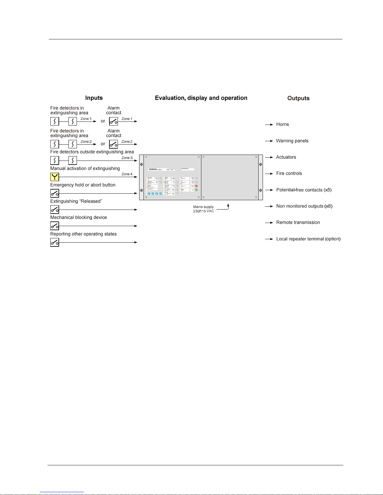
Fig. 1 XC1003-A Extinguishing control unit system overview
Use
The XC1003-A control unit can be used for:
–
Gas extinguishing installations using common extinguishing agents such as
CO2, FM200, NOVEC and Argon.
–
Deluge installations using water as the extinguishing agent.
–
Foam extinguishing installations using a mixture of water and foaming
substances.
Peripheral equipment
The following peripheral equipment can be connected to the XC1003-A control
unit.
–
Two detector lines with conventional detectors for automatic activation of
extinguishing (zones 1 and 2).
–
One detector line with conventional detectors for monitoring areas adjacent to
the extinguishing zone (zone 3).
–
Manual activation button(s) for manual activation of extinguishing (zone 4).
–
Emergency hold or abort button(s) for manual blocking of extinguishing.
–
Alarm horn(s) for acoustic reporting of a fire alarm and the activated condition.
–
Illuminated warning panel(s) for optical reporting of the impending extinguishing
operation during the activated condition time and the released condition.
–
Remote transmission device to report the "Fire alarm" and "Fault" conditions.
–
Relay for fire control with 230V contact.
–
Potential-free contacts to report the states of the XC1003-A control unit
–
Solenoid or pyrotechnical actuators to trigger the flooding.
–
Repeater indication panel for extinguishing areas with several entrances.
Page 12

System overview
12
Building Technologies
A6V10099837_a_en
Fire Safety & Security Products 12.2007
3.1 Application limitations
–
no monitored remote control panel
–
not usable for multi-sector installations with electrical cylinder allocation and full
redundancy
–
no provision to monitor a spare cylinder bank
–
no facility for secondary flooding control (low pressure installations)
–
no interface for VdS peripherals such as FBF, ÜE, FSD, SST
3.2 Specified standards and options
EN12094-1
Fulfilled
Basic functions
x
Options and the associated requirements Related XC10 configuration
4.17
Delay of extinguishing signal
Monitored control line 4, programming step 1 option 1-13 x
4.18
Signal representing the flow of extinguishing
agent
Monitored input 1, programming step 4 option 1
Monitored input 1A (XCA1016) programming step 4 option 1
x
Monitoring of the status of components
Loss of agent
Monitored input 2, programming step 4 option 10
Monitored input 1B (XCA1016) programming step 4 option 1
4.19
Non-electrical blocking device
Monitored input 2, programming step 4 option 6
x
4.20
Emergency hold
Monitored input 3, programming step 8 option 2 x
4.21
Control of flooding time
-
4.22
Initiation of secondary flooding
-
4.23
Manual only mode
Key "Mode select"
Monitored input 3, programming step 8 option 6
x
4.24
Triggering signals to equipment within the
system
Monitored control line 3, programming step 5 option 15-25 x
4.25
Extinguishing signals to spare cylinders
-
4.26
Triggering of equipment outside the system
Driver output 1 and 2
Monitored control line 5, programming step 1 option 17
x
4.27
Emergency abort
Monitored input 3, programming step 8 option 1 x
4.28
Control of extended discharge
-
4.29
Release of the extinguishing media for selected
flooding
-
4.30
Activation of alarm devices with different signals
Monitored control line 1, programming step 5 option 1-10 x
EN54-2
Fulfilled
Basic functions
x
Options and associated requirements Related XC10 configuration
7.8
Output to fire alarm device in accordance with
EN54-1 / C
Monitored control line 1, programming step 5 option 1-10 x
7.9
Output to fire alarm routing equipment in
accordance with EN54-1 / E
Monitored control line 2, programming step 3 option 17 x
7.10
Output to fire protection equipment or in
accordance with EN54-1 / G
Monitored control line 2, programming step 3 option 18 or 19 x
7.11
Delay to outputs
-
7.12
Coincidence detection
Detector zones 1, 2 and 3, programming step 6 option 1-4 x
7.13
Alarm counter
-
8.3
Fault signals from points
x
8.4
Total loss of the power supply
Separate wire from battery to upper main board XCM1001-2 x
8.9
Output to fault warning routing equipment in
accordance with EN54-1 / J
Potential-free contact Nr. 2, programming step 3 option 8-11 x
10
Test condition
x
Page 13
Standard applications
13
Building Technologies
A6V10099837_a_en
Fire Safety & Security Products 12.2007
4 Standard applications
The principal field of application of XC1003-A is room protection. Two different
system topologies are used:
–
Centralized
–
Modular
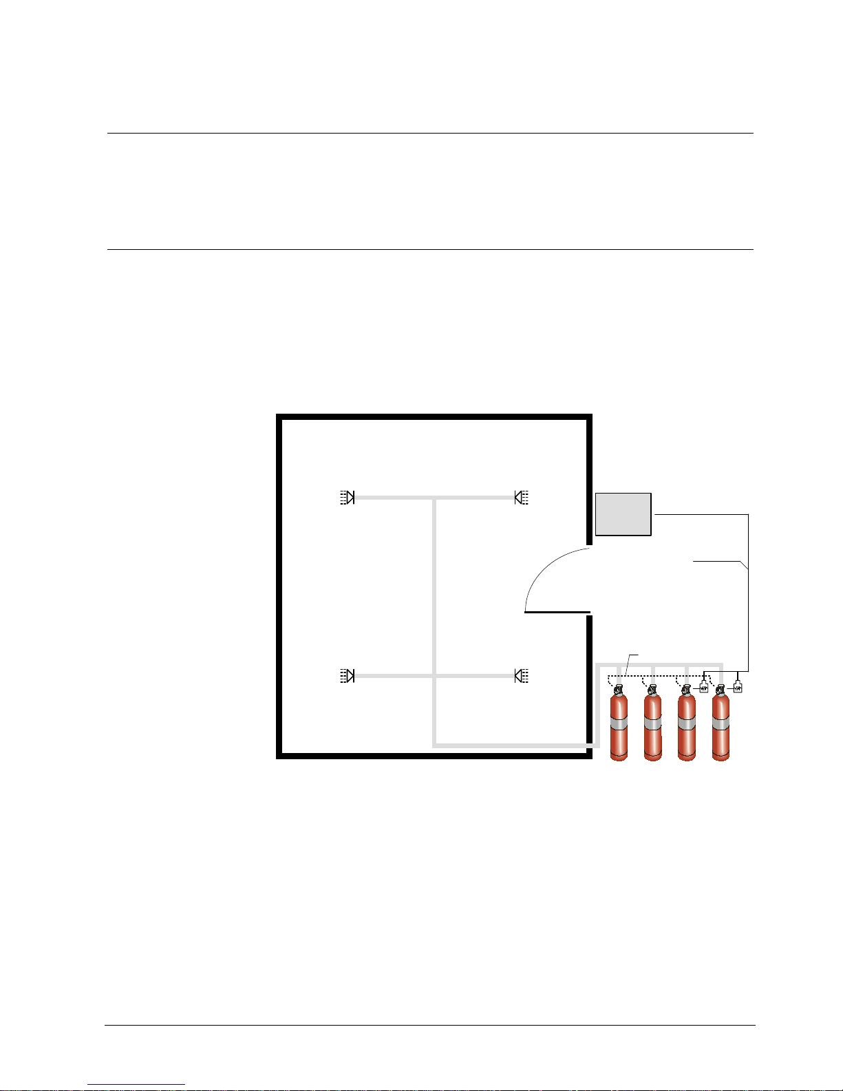
4.1 Centralized installation
Centralized systems consist of a single set of cylinders placed in a storage area.
Pipe and nozzles are used to transfer the gas from the cylinders to the protected
room. A single actuator (electromagnetic or pyrotechnical) triggers a pilot cylinder
which then activates others cylinders by pneumatic activation. Two pilot cylinders
may be used in some countries when activation redundancy is required. In that
case, two electromagnetic solenoids are connected in parallel to the monitored
control output 4 (or 5 if selected), or two pyrotechnical actuators are connected in
series to the monitored control output 4 (or 5 if selected).
Pneumatic activation
Actuator line
(Pyrotechnical or
electromagnetic actuators)
Control
unit
XC103-A
Fig. 2 Centralized installation
Page 14
Standard applications
14
Building Technologies
A6V10099837_a_en
Fire Safety & Security Products 12.2007
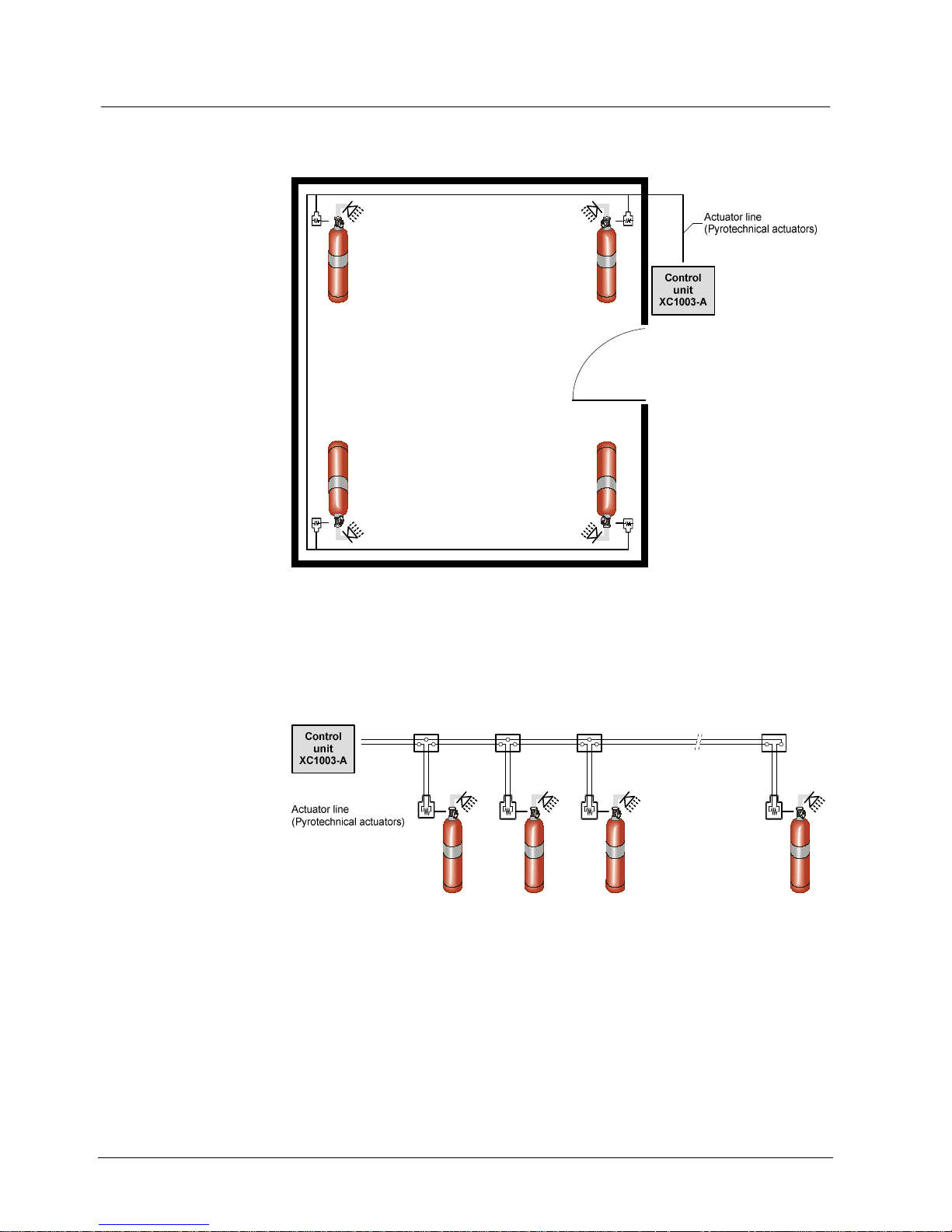
4.2 Modular installation
In contrast to centralized systems, modular systems consist of individual cylinders,
in the protected zone, with directly connected nozzles.
Fig. 3 Modular installation
For such installations, a pyrotechnical actuator is used on each cylinder. All
pyrotechnical actuators are connected in series on the monitored control line 4 (or
5 if option selected). A maximum of 10 pyrotechnical actuators in series can be
activated.
Fig. 4 Pyrotechnical installation
Page 15
Structure and function
15
Building Technologies
A6V10099837_a_en
Fire Safety & Security Products 12.2007
5 Structure and function
This chapter provides an introduction to the structure of the control unit XC1003-A,
describes the connections and provides an overview of the functions of the optical
indicators (LED), the adjusting elements and keys. Here you will also find the
description of the accessories and the technical data.
PU1
DL1
DL2
2A
2A
CN7
CN8
F2
F1
PU1
CN6
CN5
SW2
SW1
4 3 2 1
KEY
PU10
PU9
PU 6
LED34
LED26LED11
LED12
LED13
LED14
LED15
LED16
LED17
LED18
LED19
LED20
LED21
LED22
LED23
LED24
LED25
LED27
LED28
LED29
LED30
LED31
LED32
LED33
KEY 2
LED10
LED7
LED1
LED2
LED3
LED5
LED6
LED8
LED9
LED4
LD1
LD2
LD3
LD4
LD5
LD6
LD7
LD8
LD9
PU 5 PU 4 PU 3 PU 2
KEY 8KEY 9KEY 10KEY 11KEY 12
CN 1
KEY 5
+ BAT + 24V
KEY 4 KEY 6 KEY 7
PU1
LEVEL 3
PU8
B.S TEST FAB
PU7
KEY 1
KEY13
KEY14KEY15
KEY16
Pre-discharge-warning
time
………………. seconds
11
4
4
1
PU1
DL1
DL2
2A
2A
CN7
CN8
F2
F1
PU1
CN6
CN5
SW2
SW1
4 3 2 1
KEY
PU10
PU9
PU 6
LED34
LED26LED11
LED12
LED13
LED14
LED15
LED16
LED17
LED18
LED19
LED20
LED21
LED22
LED23
LED24
LED25
LED27
LED28
LED29
LED30
LED31
LED32
LED33
KEY 2
LED10
LED7
LED1
LED2
LED3
LED5
LED6
LED8
LED9
LED4
LD1
LD2
LD3
LD4
LD5
LD6
LD7
LD8
LD9
PU 5 PU 4 PU 3 PU 2
KEY 8KEY 9KEY 10KEY 11KEY 12
CN 1
KEY 5
+ BAT + 24V
KEY 4 KEY 6 KEY 7
PU1
LEVEL 3
PU8
B.S TEST FAB
PU7
KEY 1
KEY13
KEY14KEY15
KEY16
Pre-discharge-warning
time
………………. seconds
12
3
2
6
10
100Ω 3W
589
PU3 PU1 PU2
DL1
RT FAULT RT ALARM
OUPUT RT
PU4 PU3 PU1 PU2
DL1
RT FAULT RT ALARM
OUPUT RT
PU4
7
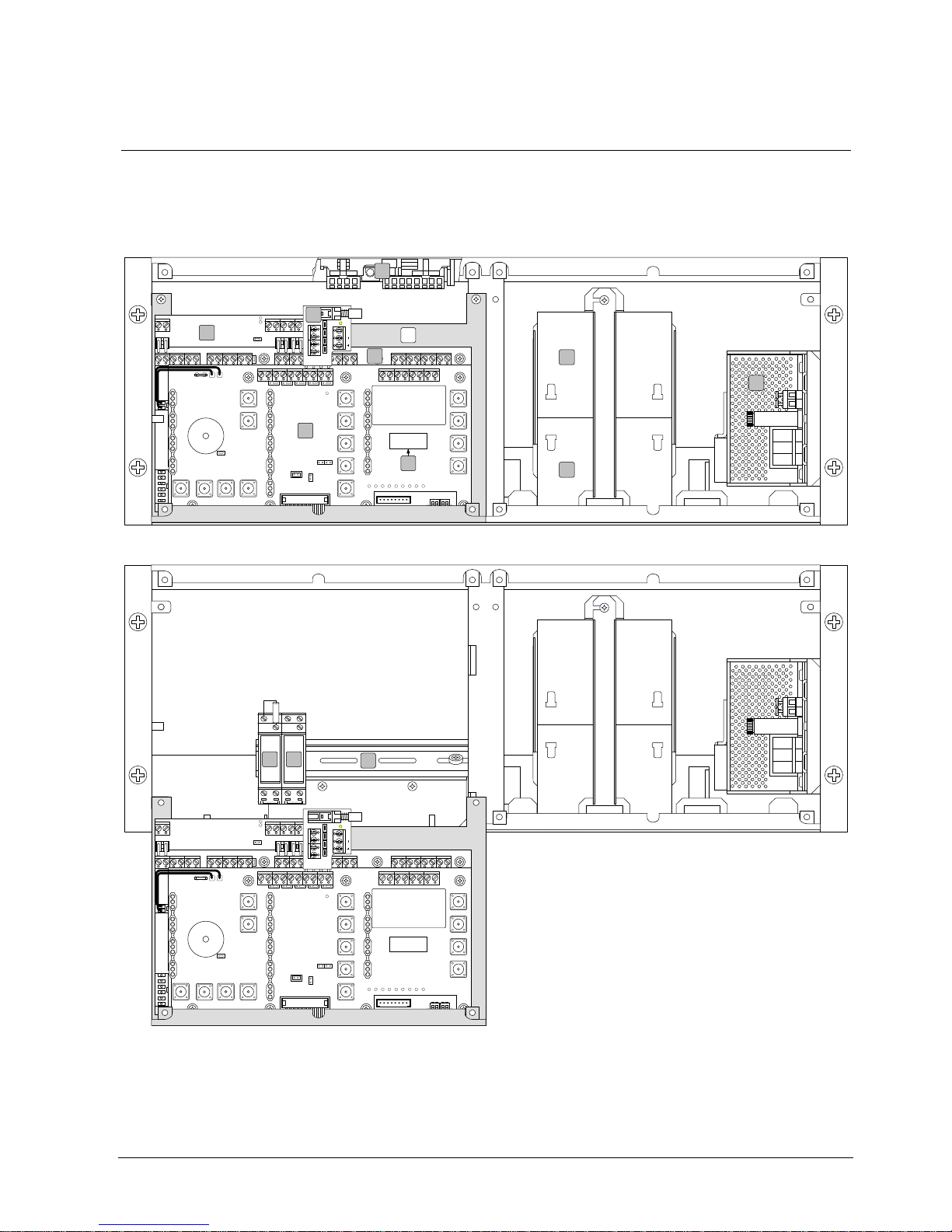
Fig. 5 Rack XC1003-A with electronics components
Page 16

Structure and function
16
Building Technologies
A6V10099837_a_en
Fire Safety & Security Products 12.2007
The basic equipment of the extinguishing control unit XC1003-A consists of
components 1 to 4. Depending on requirements, the control unit can be provided
with accessory parts 5 to 9:
1. FCP1004-E power supply unit with charger
2. XCM1001-1 main board (lower level)
3. XCM1001-2 main board (upper level)
4. Rechargeable batteries 4.5 Ah or 7.2 Ah (see chapter 7.4)
5. XCA1110 pyrotechnical actuator kit (option)
6. XCA1016 add-on module to split the monitored input 1 into the two separate
circuits "1A" and "1B" (option)
7. FCA1005-D RT isolation card for preventing remote transmission of alarms
and faults (option)
8. FDCI222 or FDCIO222 module for the connection to a fire detection system
(option)
9. Z3B171 relay module for fire controls (option)
10. Removable support main boards XCM1001-1 and XCM1001-2
11. DIN rail TS35 to install components such as relays, terminals, etc.
12. Label for indication of pre-discharge-warning time selected
Page 17
Structure and function
17
Building Technologies
A6V10099837_a_en
Fire Safety & Security Products 12.2007
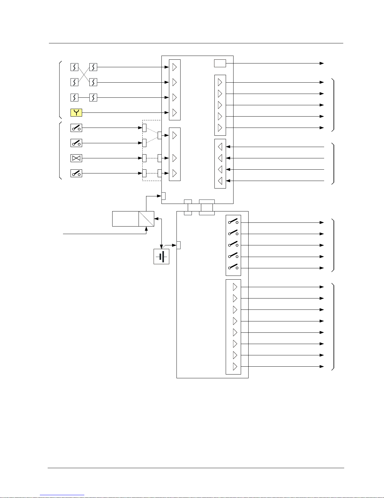
5.1 Block diagram
LIN4
Horn
RT-alarm or other application
Actuator delayed
Actuator immediate or other application
Mains supply
Output 24V / 0.5A max. (for internal use)
CL6
CL12
CL13
CL14
CL15
CN8
CL10
CN6
CN1
XCM1001-1
CL11
CL16
Detector lines
1
2
3
4
5
Monitored inputs
Monitored control linesPotentiel-free contactsDriver outputs
CL7
CL6
CL7
CL8
CL9
CL5 1
2
3
4
5
RT-alarm
RT-fault
Fire alarm or other application
Manual only
Autom. & Man. blocked
Fire alarm / Activated / Released
Released
1
2
3
4
5
CL1
CL2
6
7
8
CL3
CL4
Emergency hold/abort
Activated / Released
Fire alarm
Activated
Manual only mode
Autom. & Man. blocked
Manual release
CL4
LIN1
CL1
LIN2
CL2
LIN3
CL3
Discharged
Loss of agent
Mech. blocking device
Emergency hold or abort
XCA1016
1
2
3
AC
DC
FCP1004E
12V / 4.5Ah or 7.2Ah (x2)
XCM1001-2
CN7
1A
1B
2
3
CL8
CL9
CL10
+ BAT
+ / -
Reset
Silence buzzer or other application
Control inputs
Fault or other application
Silence Re-sound horn or other application
1
2
3
4
Warning panel
Z. 1
Z. 2
Z. 3
230 / 115 VAC
Z. 4
Fig. 6 Block diagram of the XC1003-A control unit
Page 18

Structure and function
18
Building Technologies
A6V10099837_a_en
Fire Safety & Security Products 12.2007
5.2 Connections
The following is a brief, overview of the location of the connections.
On the top of the power unit (see chapter 5.2.1) are the mains connection and
voltage selection.
The XCM1001-1 main board (see chapter 5.2.2 and 5.2.3) principally includes:
–
Detector lines
–
Control inputs
–
Monitored inputs
–
Monitored control lines
The XCM1001-2 main board (see chapter 5.2.4) principally includes:
–
Driver outputs
–
Potential-free contacts
Page 19

Structure and function
19
Building Technologies
A6V10099837_a_en
Fire Safety & Security Products 12.2007
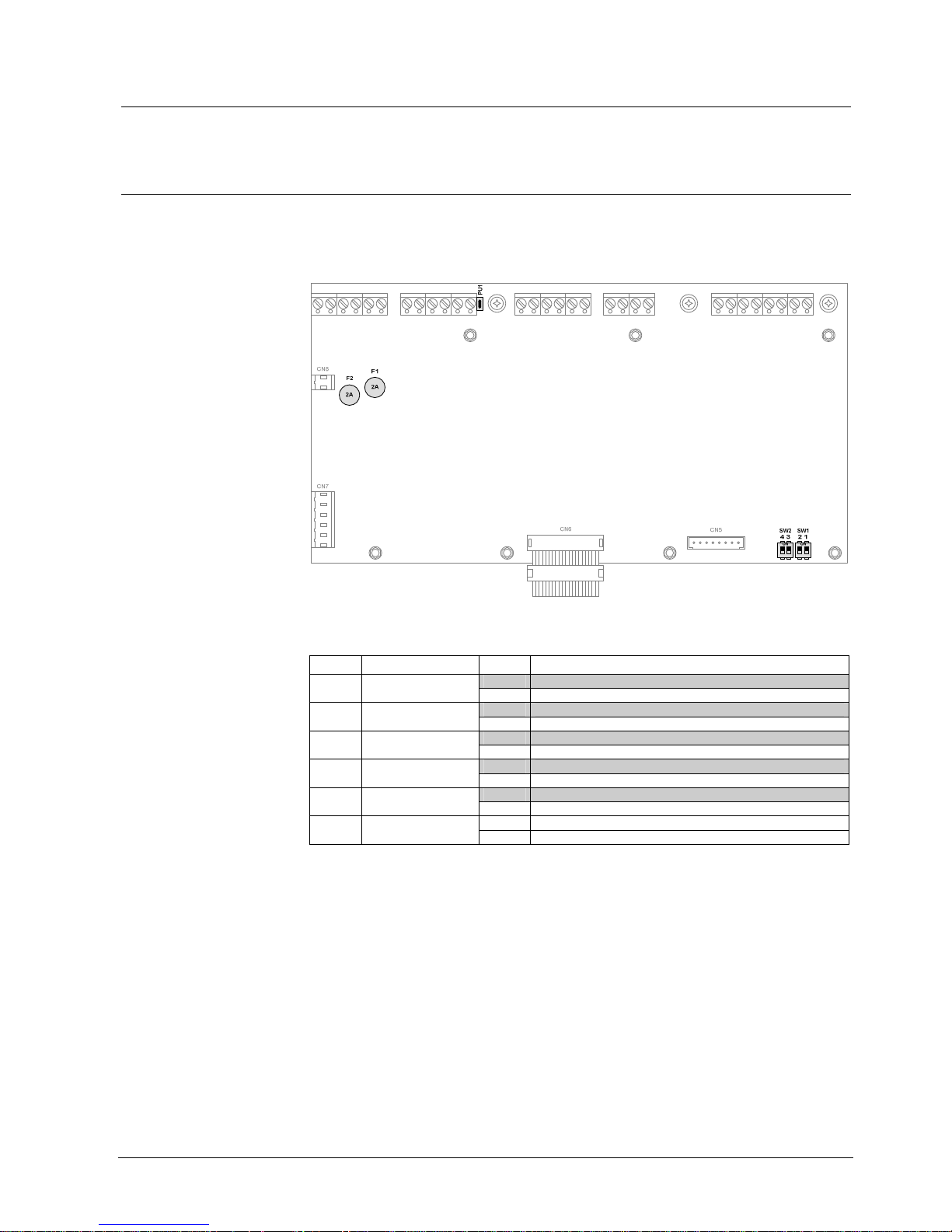
5.2.1 Power supply FCP1004-E
Fig. 7 Components of the power unit FCP1004-E
Ref. Function Remarks
1 Terminal block for setting mains voltage to
115 V
Jumper set for 115 V only (use insulated wire)
2 Terminal block for mains connection
3 4 AT/250 V 20x50mm high break mains fuse
4 Jumper for system start without mains
power
Remove after system start
5 LED green “mains operation” (inside but
visible from the front)
Not lit in the event of power failure
6 Heat sensor for temperature compensation
7 Batteries connection
8 XCM1001-1 connection
9 Connection required in case EN54-2 option
with requirement "Total loss of power" is
mandatory (Mainly for FR).
Connect wire between +battery connection
and +BAT terminal of XCM1001-2
Protection by fuse 630 mA
This product shall be installed, commissioned and maintained by trained service personnel in
accordance with the following:
1. IEE regulations for electrical equipment in buildings
2. Codes of practice
3. Any instructions specifically advised by the manufacturer
This equipment is designed to operate from 230V 50Hz mains supplies. It must be connected to a
protective earthing conductor in the fixed wiring of the installation, and a readily accessible double
pole disconnect device meeting the requirements of EN60950/IEC950 which disconnects live and
neutral simultaneously, shall be incorporated in the fixed wiring.
Failure to ensure that all conductive accessible parts of this equipment are adequately bonded to the
protective earth will render the equipment unsafe.
1. Ensure mains power is switched off
2. Remove mains fuse (3)
3. Connect the mains cable to the FCP1004E power supply terminals (2) Protective earth, live and
neutral)
4. Attach the cable with 2 plastic fastenings
This control panel is environmental class A and is designed for indoor use only at temperatures
between -5°C (+/- 3) and +40°C (+/- 2) and with a m aximum relative humidity of 95%.
The IP rating for the enclosure is IP30. Operation outside of these limits may render the equipment
unsafe.
Page 20
Structure and function
20
Building Technologies
A6V10099837_a_en
Fire Safety & Security Products 12.2007
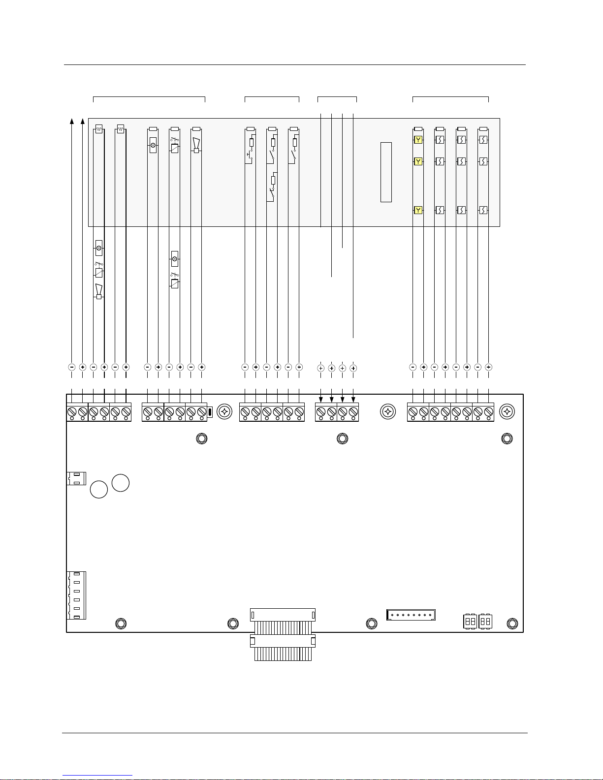
5.2.2 Connections on XCM1001-1 lower main board without add-on module
Standard
2A
2A
Emergency hold or abort
Loss of extinguishing agent
Extinguishing discharged
CN7
CN8
F2
F1
PU1
CN6
CN5
SW2 SW1
4 3 2 1
Alarm horn
Monitored inputs
3 2 1
3K3 3K3 3K3
0K68
0K68
CL16 CL15 CL14 CL13 CL12 CL11 CL10 CL9 CL8 CL7 CL6 CL4 CL3 CL2 CL1
121212
LIN4
Detectors to extinguishing area
Manual release
Detector lines
LIN3
LIN2
LIN1
Detectors to extinguishing area
Detectors outside exting. area
3K3 3K3 3K3 3K3
3 2 1
12121212
4
Reset
Control inputs
3 2 14
1212
Silence Re-sound horn or other application
Fault or other application
Silence buzzer or other application
Supply for internal devices
Actuator delayed
Warning panel
RT-alarm
Monitored control lines
5 34 2 1
..2A ..0.5A ..0.5A..2A ..0.5A
Actuator immediate
24V
..0.5A
12 12 12 12 12 12
Options
Options
EOL
(*)
EOL
(*)
EOL
(*)
(*) Line termination of monitored control lines 1 … 3:
Use FCE1002 (enclosed with delivery from the factory)
Options
Other application
1K2 0K68
NONC
or
Fig. 8 Connections of the XCM1001-1 lower main board without add-on module
Page 21
Structure and function
21
Building Technologies
A6V10099837_a_en
Fire Safety & Security Products 12.2007
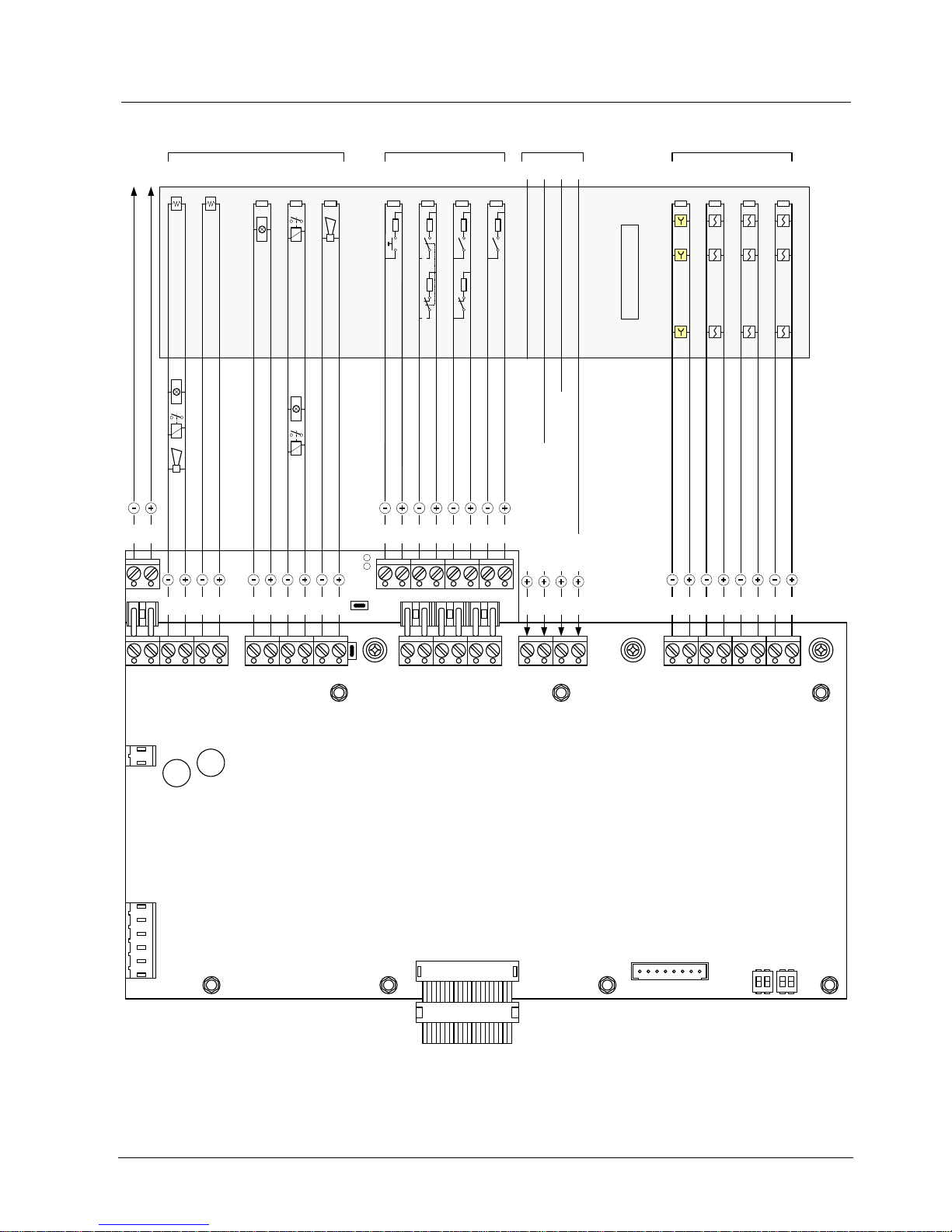
5.2.3 Connections of the XCM1001-1 lower main board with add-on module
Standard
2A
2A
PU1
DL1
DL2
CN7
CN8
F2
F1
PU1
CN6
CN5
SW2 SW1
4 3 2 1
Reset
Supply for internal devices
LIN4
Detectors to extinguishing area
Manual release
Actuator delayed
Warning panel
Alarm horn
RT-alarm
Monitored control lines Monitored inputs Control inputs Detector lines
5
3 2 1A
34 2 1
..2A ..0.5A ..0.5A..2A ..0.5A
3 2 14
LIN3
LIN2
LIN1
Detectors to extinguishing area
Detectors outside exting. area
Actuator immediate
24V
..0.5A
EOL
(*)
3K3 3K3 3K3 3K3
3 2 1
12
12 12 12 12 12 1212 12121212
Extinguishing discharged
3K3
0K68
12
Loss of extinguishing agent
3K3
12
Emergency hold or abort
3K3
0K68
12
Mechanical blocking device
3K3
12
1B
Silence Re-sound horn or other application
Fault or other application
Silence buzzer or other application
4
Options
Options
CL16 CL15 CL14 CL13 CL12 CL11 CL10 CL9 CL8 CL7 CL6 CL4 CL3 CL2 CL1
CL3CL2CL4CL5
CL1
or
0K680K68
1K2 0K68
ClosedOpen
(*) Line termination of monitored control lines 1 … 3:
Use FCE1002 (enclosed with delivery from the factory)
EOL
(*)
EOL
(*)
Options
Other application
Fig. 9 Connections of the XCM1001-1 lower main board with add-on module
Page 22
Structure and function
22
Building Technologies
A6V10099837_a_en
Fire Safety & Security Products 12.2007
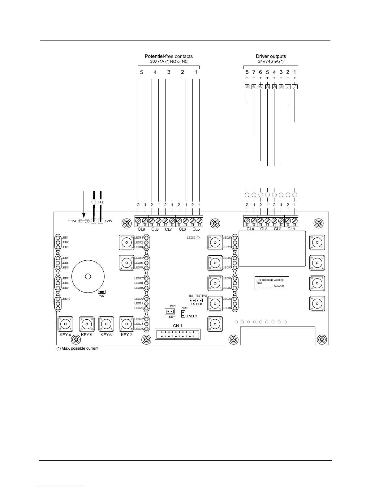
5.2.4 Connections of the XCM1001-2 upper main board
KEY 2
LD1
LD2
LD3
LD4
LD5
LD6
LD7
LD8
LD9
KEY 8KEY 9KEY 10KEY 11KEY 12
To lower main board via connector CN8 (Supply 24V)
To positive of battery to provide function ’’total loss of power’’
Autom. & Man. blocked
RT-alarm
RT-fault
KEY 1
KEY13
KEY14
KEY15
KEY16
Manual only
Fire alarm or other application
Emergency hold / abort or other application
Autom. & Man. blocked
Manual only
Released
Activated
Activated / Released or other application
Fire alarm
Fire alarm / Activated / Released
Fig. 10 Connections of the XCM1001-2 upper main board
XC10 provides EN54-2 option with requirements “Total loss of power”. This option
is mainly mandatory in France. When selected, “System fault” led and buzzer is
activated continuously for at least 1 hour after low discharge battery switch off (in
case the battery voltage fails below 21 V).
This option can be selected by wiring the +BAT terminal to the positive voltage of
batteries (use of remaining power of the battery).
Page 23
Structure and function
23
Building Technologies
A6V10099837_a_en
Fire Safety & Security Products 12.2007
5.3 Adjusting elements
Certain functions can be parameterized using the adjusting elements.
5.3.1 Adjusting elements of the XCM1001-1 lower main board
This board contains parameters for:
–
Disable earth fault monitoring
–
Change type of fire detector
Fig. 11 Adjusting elements of the XCM1001-2 upper main board
Ref. Function State Parameter
ON Activated (factory setting) PU1 Earth short
monitoring unit
OFF De-activated
ON Detector "Siemens" without current limiting (factory setting) SW1-1 Detector line 1
OFF Detector "Synova" with current limiting
ON Detector "Siemens" without current limiting (factory setting) SW1-2 Detector line 2
OFF Detector "Synova" with current limiting
ON Detector "Siemens" without current limiting (factory setting) SW2-3 Detector line 3
OFF Detector "Synova" with current limiting
ON 1) Detector "Siemens" without current limiting (factory setting) SW2-4 Detector line 4
(manual release)
OFF 1) Detector "Synova" with current limiting
Fit Fuse “F1” for control line 4 F1 / F2 Pluggable fuse 2A
Fit Fuse “F2” for control line 5
1
) Manual activation buttons with 820 Ohm resistor or with Z-diode 5.6 V with LED in line function on
both settings correct
Page 24
Structure and function
24
Building Technologies
A6V10099837_a_en
Fire Safety & Security Products 12.2007
5.3.2 Adjusting elements of the XCM1001-2 upper main board
This board contains parameters for:
–
Permanently activate of operating level 2
–
Change the contact type NO/NC
–
Disable activation of the buzzer
–
Activate the calibration procedure for control lines 4 and 5
Fig. 12 Adjusting elements of the XCM1001-2 upper main board
Ref. Function
Jumper
pos.
Parameter
ON Permanent access PU1 Operating access level 2
OFF Access only using code (factory setting)
ON Right NO contact (factory setting) PU2 Potential-free contact "RT-alarm"
(programmable in step 3/option 1-4)
ON Left NC contact
ON Right NO contact (factory setting) PU3 Potential-free contact "RT-fault"
(programmable in step 3/ option 8-11)
ON Left NC contact (schematic in power off state)
ON Right NO contact (factory setting) PU4 Potential-free contact "Fire alarm"
(programmable in step 3/ option 5-6)
ON Left NC contact
ON Right NO contact (factory setting) PU5 Potential-free contact "Manual only"
ON Left NC contact
ON Right NO contact (factory setting) PU6 Potential-free contact "Autom. & Man.
blocked"
ON Left NC contact
ON Activated (factory setting) PU7 Temporary disabling of buzzer
OFF Not activated (only for servicing)
PU8 Factory test OFF (factory setting)
PU9 Factory test OFF (factory setting)
ON Calibration activated PU10
Calibrating the control lines 4 and 5
(details see chapter 10.6)
OFF Calibration not activated (factory setting)
Page 25
Structure and function
25
Building Technologies
A6V10099837_a_en
Fire Safety & Security Products 12.2007
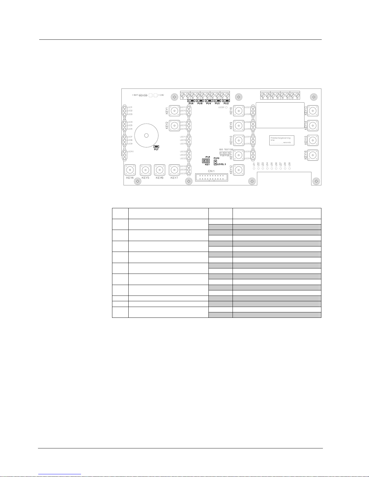
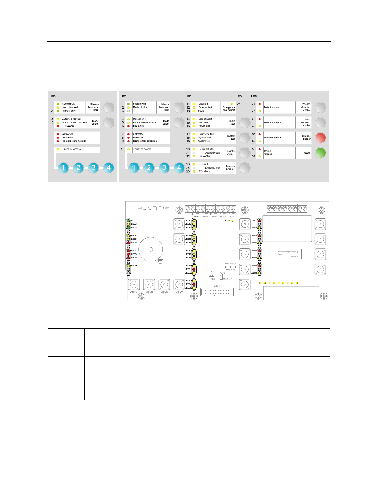
5.4 Indicator elements
The indicator elements (LEDs) are on the XCM1001-2 main board. LEDs 1 to 34
for operating states are visible on the front of the housing. Service LEDs (LD1 to
LD9) provide fault information and are not visible from the outside.
Alternative configuration
Programming step 10/ option 2
Standard configuration
Programming step 10/ option 1
Fig. 13 Indicator elements, housing cover view
KEY2
LD1
LD2
LD3
LD4
LD5
LD6
LD7
LD8
LD9
KEY8KEY9KEY10KEY11KEY12
KEY1
KEY13
KEY14
KEY15
KEY16
Fig. 14 Indicator elements, XCM1001-2 upper main board view
Indicator elements (LED1 to LED34)
Ref. / Colour Identification State Function
LED1 / Green System ON Lit System in operation (microcomputer is running)
- Mechanical blocking device is in the "Open" position
Lit Mechanical blocking device is in the "Closed" position
LED2 / Yellow Mech. blocked
Fast Mechanical blocking device in wrong position
- - Not used LED3 / Green
Manual only Lit
Alternative (step 10 = option 2):
Triggering by fire detector is blocked, initialized by:
– KEY2 "Mode select"
– Disabling of detector zone 1 or 2
– Switching of detector zone 1 or 2 to "Test mode"
– Monitored inputs 2 and 3 (depending on programming, see steps 4 & 8)
– Control inputs 2 and 3 (depending on programming, see step 15)
Page 26

Structure and function
26
Building Technologies
A6V10099837_a_en
Fire Safety & Security Products 12.2007
Indicator elements (LED1 to LED34)
Ref. / Colour Identification State Function
Manual only Lit Triggering by fire detector is blocked, initialized by:
– KEY2 "Mode select"
– Disabling of detector zone 1 or 2
– Switching of detector zone 1 or 2 to Detector "Test mode"
– Monitored inputs 2 and 3 (depending on programming, see steps 4 & 8)
– Control inputs 2 and 3 (depending on programming, see step 15)
LED4 / Yellow
Autom. & Manual Lit
Alternative (step 10 = option 2):
Automatic and manual activation of extinguishing is possible
LED5 / Yellow Autom. & Man. blocked Lit Triggering by fire detector and manual release is blocked, initialized by:
– KEY2 "Mode select"
– Disabling of detector zones 1 & 2 and manual release
– Switching of detector zone 1 & 2 and manual release to "Test mode"
– Monitored inputs 2 and 3 (depending on programming, see step 4 & 8)
– Control input 2 (depending on programming, see step 15)
LED6 / Red Fire alarm Lit On "Alarm" zone 1 or 2 or 3 (if zone 3 is programmed in step 11 option 9, 10, 12
or 13)
Fast Extinguishing is in the pre-activated condition (first fire alarm indication) LED7 / Red Activated
Lit
–
If "Activated" condition is initiated and timer is running
–
If timer runs and state "Emergency hold/abort" is engaged
–
If flooding of extinguishing agent is started
Extinguishing agent is released (reporting by monitored input 1 or 1A)
Variant: Always in steady mode if step 10 = option 4
Fast
Alternative (step 4 = option 3):
State "Released" is indicated as soon as control line 4 is activated (simulation of
"Released" condition)
LED8 / Red Released
Lit If "Released" is not reported within 30 sec after control line 4 has been activated
(can be suppressed if step 4 = option 5)
Contact 1 "RT-alarm" is in state "Active" (function may be inoperative) Lit
In addition (step 3 = option 13):
Contact 2 "RT-fault" is in state "Active"
LED9 / Red Remote transmission
-
Alternative (step 3 = option 14 ):
Facility “Remote transmission” is not used
Lit Operating access level 2 is provided either by code or control inputs 3 and 4
(depending on programming, see step 15)
Timeout if access is provided by code: Void 3 minutes after the last button was
pressed
LED10 / Yellow Operating access
Slow "System test" mode is activated
LED11 / Yellow Disabled Lit A system component is disabled, initialized by the following:
– Detector zones 1 to 3 are disabled or in "Detector Test" mode
– Manual release is disabled or in "Test mode"
– Alarm horn/valve control is disabled
– Fire control is disabled
– RT-alarm is disabled
– RT-fault is disabled
– State "Manual only" is activated
– State "Autom. & Man. blocked" is activated
– Control input 2 is active (depending on programming, see step 15)
– Calibration processing of monitored control line 4 and 5
– Unit is in “System test” mode
LED12 / Yellow Detector test Slow Detector zones 1 to 3 or manual release are in "Test mode"
Fast A system component is in the "Fault" state, initialized by the following:
– Detector line 1 to 3 is on open circuit or short circuit
– Manual release is on open circuit or short circuit
– Monitored inputs 1 to 3 is on open circuit or short circuit
– Control lines 1 to 5 is on open circuit or short circuit or fuse blown (control lines
4 and 5)
– Earth fault
– Battery is disconnected or very low charge
– Mains power off (after expiry of the mains delay time)
– Control inputs 3 and 4 are active (depending on programming, see step 15)
– State discharged not reported within 30sec after release
– Calibration processing of monitored control lines 4 and 5
LED13 / Yellow Fault
Lit Processor failure (the control unit is not operating)
Page 27

Structure and function
27
Building Technologies
A6V10099837_a_en
Fire Safety & Security Products 12.2007
Indicator elements (LED1 to LED34)
Monitored input 1 is in state "Active 2"
Alternative (step 4 = option 2): Monitored input 1 is in state "Inactive 2"
LED14 / Yellow Loss of agent Fast
Alternative (step 4 = option 10): Monitored input 2 is in state "Active 1+2" or
"Inactive 2"
LED15 / Yellow Earth fault Fast A system component has an earth fault
Fast Battery is disconnected or very low charge LED16 / Yellow Power fault
Slow
–
Mains power supply is off (after expiry of the mains delay time) or too low
–
Control input 3 is active (depending on programming, see step15)
LED17 / Yellow Peripheral fault Fast
–
Monitored input 1 line is on open circuit or short circuit
–
Monitored input 2 line is on open circuit or short circuit
–
Monitored control line 3 is on open circuit or short circuit
–
Monitored control line 2 is on open circuit or short circuit if step 3, option 22, 23
or 24 is selected
–
Monitored control line 5 is on open circuit or short circuit or fuse blown if step 1,
option 18, 19 or 21 is selected
–
During calibration processing of monitored control line 5 if step 1, option 18 or
19 is selected
LED18 / Yellow System fault Lit Processor fault (the control unit is not operating)
Lit The unit is in "System test Mode 1" (see chapter 10.7) LED19 / Yellow System test
Slow The unit is in "System test Mode 2" (see chapter 10.7)
Lit
–
Monitored control line 1 is disabled
–
Monitored control line 4 is disabled
–
Monitored control line 2 is disabled if step 3, option 20 or 21 is selected
–
Monitored control line 5 is disabled if step 1, option 14, 15, 16 or 21 is selected
Fast
–
Monitored control line 1 is on open circuit or short circuit
–
Monitored control line 4 is on open circuit or short circuit or fuse blown
–
Monitored control line 2 is on open circuit or short circuit if step 3, option 20 or
21 is selected
–
Monitored control line 5 is on open circuit or short circuit or fuse blown if step 1,
option 14, 15, 16 or 20 is selected
–
During calibration processing of monitored control line 4 and 5
LED20 / Yellow Horn/Actuator
Slow
–
Monitored control line 1 is in state "Horn test" (see chapter 10.4)
–
Monitored control line 1 is in state "Active" in "System test Mode 2" (see
chapter 10.7)
Lit
–
Monitored control line 4 is in state "Active" in "System test Mode 1" (see
chapter 10.7)
–
Calibration processing of monitored control line 4 and 5 is terminated
LED21 / Red -
Slow Monitored control line 4 is in state "Active" in "System test Mode 2" (see chapter
10.7)
Lit – Driver outputs 1, 2, 8 are disabled (depending on programming, see step 16)
– Monitored control line 2 is disabled if step 3, option 18 or 19 is selected
– Monitored control line 5 is disabled if step 1, option 17 is selected
Fast
–
Monitored control line 2 open circuit or short circuit if step 3, option 18 or 19 is
selected
–
Monitored control line 5 open circuit or short circuit or fuse blown if step 1,
option 17 is selected
–
During calibration processing of monitored control line 5 if step 1, option 17 is
selected
LED22 / Yellow Fire control
Slow
–
Monitored control line 3 is in state "Warning panel test"
–
Monitored control line 3 is in state "Active" in "System test Mode 2" (see
chapter 10.7)
Contact 2 is disabled (function may be inoperative) Lit
Alternative (step 13 = option 10):
Automatically activated if access is provided to operating level 2
-
Alternative (step 3 = option 14):
Inoperable, if facility "Remote transmission" not used
LED23 / Yellow RT-fault
Fast Control input 3 or 4 with option "RT-fault" is "Active" (see step 15)
Lit
–
Monitored control line 5 is in state "Active" in "System test Mode 1" (see
chapter 10.7)
–
Calibration processing of monitored control line 4 and 5 is terminated
LED24 / Red -
Slow Monitored control line 5 is in state "Active" in "System Test Mode 2" (see chapter
10.7)
–
Contact 1 is disabled
–
Monitored control line 2 is disabled if step 3, option 17 is selected
Lit
Alternative (step 13 = option 10):
Automatically activated if state operating access 2 is provided
-
Alternative (step 3 = option 14 ):
Inoperable, if facility "Remote transmission" facility not used
LED25 / Yellow RT-alarm
Fast Monitored control line 2 is open circuit or short circuit if step 3, option 17 is
selected
Lit – Monitored input 3 is in state "active 1" (depending on programming, see step 8)
– Control input 2 or 4 is active (depending on programming, see step 15)
LED26 / Yellow Emergency
Hold/Abort
Fast Monitored input 3 is on open circuit or short circuit
Page 28

Structure and function
28
Building Technologies
A6V10099837_a_en
Fire Safety & Security Products 12.2007
Indicator elements (LED1 to LED34)
Lit Zone 1 is in alarm (or test alarm) LED27 / Red Detector zone 1
Slow Zone 1 is in first alarm
Lit Zone 1 is disabled
Slow Zone 1 is in "Test mode"
LED28 / Yellow Detector zone 1
Fast Zone 1 is open circuit or short circuit (fault)
Lit Zone 2 is in alarm (or test alarm) LED29 / Red Detector zone 2
Slow Zone 2 is in first alarm
Lit Zone 2 is disabled
Slow Zone 2 is in "Test mode"
LED30 / Yellow Detector zone 2
Fast Zone 2 is open circuit or short circuit (fault)
Lit Zone 3 is in alarm (or test alarm) LED31 / Red Detector zone 3
Slow Zone 3 is in first alarm
Lit Zone 3 is disabled
Slow Zone 3 is in "Test mode"
LED32 / Yellow Detector zone 3
Fast Zone 3 is open circuit or short circuit (fault)
Lit Manual release is in alarm (or test alarm) LED33 / Red Manual release (Zone 4)
Slow Manual release is in first alarm
Lit Manual release is disabled
Slow Manual release is in "Test mode"
LED34 / Yellow Manual release (Zone 4)
Fast Manual release is open circuit or short circuit (fault)
Service LEDs (LD1 to LD9)
Ref. / Colour Identification State Fault Information
Lit Short circuit LD1 / Yellow Monitored control line 1
Fast Open circuit
Lit Short circuit LD2 / Yellow Monitored control line 2
Fast Open circuit
Lit Short circuit LD3 / Yellow Monitored control line 3
Fast Open circuit
Lit Short circuit
Fast Open circuit or fuse blown
LD4 / Yellow Monitored control line 4
Slow Calibration out of tolerance
Lit Short circuit
Fast Open circuit or fuse blown
LD5 / Yellow Monitored control line 5
Slow Calibration out of tolerance
Lit Short circuit LD6 / Yellow Monitored input 1
Fast Open circuit
Lit Short circuit LD7 / Yellow Monitored input 2
Fast Open circuit
Lit Short circuit LD8 / Yellow Monitored input 3
Fast Open circuit
Lit No mains voltage
Fast Battery fault
LD9 / Yellow Mains power supply
Slow Battery very low
Page 29

Structure and function
29
Building Technologies
A6V10099837_a_en
Fire Safety & Security Products 12.2007
5.5 Operating elements
The operating elements (keys) are on the main board, upper level. The keys can
be pressed on the main board and, when the housing is closed, by using the
membrane keypad. Basically, the function assigned to the key is labeled on the
left, next to the membrane key. Various keys have several functions.
Fig. 15 Operating elements, housing cover view
KEY2
LD1
LD2
LD3
LD4
LD5
LD6
LD7
LD8
LD9
KEY8KEY9KEY10KEY11KEY12
KEY1
KEY13
KEY14
KEY15
KEY16
Fig. 16 Operating elements, XCM1001-2 upper main board view
Keys 4 to 7 are digit keys. These are used for entering the access codes for
release of operation, for the system test and for configuring user functions.
Page 30

Structure and function
30
Building Technologies
A6V10099837_a_en
Fire Safety & Security Products 12.2007
Ref. Identification Access
level
Function
KEY1 Silence
Re-sound
horn
2 Deactivation/activation of monitored control line 1 and, depending on programming also control
line 2 or 5 (blocked in state "Activated" until state "Released" occurs and while timer is running)
Also used from access level 3 to select the programming steps (see chapter 11.6)
KEY2 Mode select 2 Switching mode between:
– Not blocked or "Autom. & Manual" (ready to operate)
– "Autom. blocked" or "Manual only"
– "Autom. & Man. blocked"
Also used from access level 3 to select the programming steps (see chapter 11.6)
KEY4
to
KEY7
Operating access 1 Enabling of access level 2 (enter digits "4233")
Also used from access level 2 for:
– Trigger "Horn test" (see chapter 10.4)
– Trigger "Warning panel test" (see chapter 10.5)
– Switch to "Program user functions" mode (see chapter 11)
– Access to "Performing system test" (see chapter 10.7)
– Access to "Reset user functions to default or application settings" (see chapter 11.4)
KEY8 - - Not used (factory setting)
KEY9 Lamp test 1 Pressing the key activates all LEDs and buzzer for 5 seconds (see chapter 10.2)
Also used from access level 2 for:
– Trigger "Horn test" (see chapter 10.4)
– Trigger "Warning panel test" (see chapter 10.5)
KEY10 System test 2 System setting in mode "System test" 2)
Possible only after previous input of a code (see chapter 10.7)
KEY11 Disable/
Enable
2 Disabling of horn, actuator and fire control:
– First pressing disables horn and actuator (monitored control lines 1 and 4), and possibly 2
and 5 if these lines are programmed as horn or actuator (see step 1 and step 3) 3)
– Second pressing disables fire control (driver outputs 2, 8 and 1 and possibly control line 2 or
5. If these monitored control lines are programmed as fire control, see step 1 and 3 4)
– Third pressing disables both
– Fourth pressing enables both
Disabling is not possible while the system is in the "Activated" condition
Disable/
Enable
2 Disabling of "RT-alarm" and "RT-fault" (inoperable if no remote transmission device is used):
– First pressing disables contact 2 "RT-fault"
– Second pressing disables contact 1 "RT-alarm" and control line 2 if step 3 option 17
– Third pressing disables both
–
Fourth pressing enables both
KEY12
Not used -
Alternative (step 3 = option 14): Inoperable
2
) Monitored control line 5 only when in programming step 1 options 14 and 15 are set (see chapter 11.6.1)
3
) Driver outputs: only when in programming step 16 options 9, 18 and 20 are set (see chapter 11.6.16)
4
) Control line 5 only when in programming step 1 option 17 is set, control line 3 only if programming step 3 option 18 or 19 (see chapter
11.6.1)
ZONES
disable/
enable
2 Disabling of detector zones 1 to 3 and manual release:
– First pressing disables detector zone 1
– Second pressing disables detector zone 2
– Third pressing disables detector zone 1 and 2
– Fourth pressing disables detector zone 3
– Fifth pressing disables manual release
– Sixth pressing disables zones 1 to 3 and manual release
– Seventh pressing enables zones 1 to 3 and manual release
Also used from access level 3 to select the options in programming steps (see chapter 11.6)
KEY13
Not used -
Alternative (step 11 = option 3): Inoperable
ZONES
det. test/
enable
2 Setting of the zones 1 to 3 and manual release to "Test mode":
– First pressing sets zone 1 to "Test mode"
– Second pressing sets zone 2 to "Test mode"
– Third pressing sets zones 1 and 2 to "Test mode"
– Fourth pressing sets zone 3 to "Test mode"
– Fifth pressing sets zone 1 to 3 to "Test mode"
– Sixth pressing sets manual release to "Test mode"
– Seventh pressing sets zones 1 to 3 and manual release to "Test mode"
– Eighth pressing sets zones 1 to 3 and manual release to "Normal mode"
Also used from access level 3 to select the options in programming steps (see chapter 11.6)
KEY14
Not used -
Alternative (step 11 = option 3): Inoperable
Silencing the buzzer upon alarm and fault
Also deactivates contact 2 "RT-fault" if step 3, option 8 is selected
1
Alternative (step 13 = option 4): Silencing the buzzer upon alarm and fault and silencing horn
upon fire alarm
KEY15 Silence buzzer
2
Alternative (step 12 = option 5): Only accessible on access level 2
Also used from access level 3 to select the options in programming steps (see chapter 11.6)
Reset of the system upon alarm
Not available in the state "Activated" and as long as the valve control is active (flooding time)
Alternative (step 9 = option 12): Reset is not available as long as zone 4 is an alarm or
monitored input 1 is in state "active 1" or control line 1 (horn) is activated
KEY16 Reset 2
Alternative (step 13 = option 8): Also to reset fault
Also used from access level 3 to select the options in programming steps (see chapter 11.6)
Page 31

Structure and function
31
Building Technologies
A6V10099837_a_en
Fire Safety & Security Products 12.2007
5.6 Accessories
This chapter describes optional accessories that you can use.
5.6.1 Z3B171 Relay module
Relay module for switching the fire protection devices. The extinguishing control
unit provides space for up to 10 relays. Contact rating 230 V max. 10 A.
Fig. 17 Z3B171 Relay module
5.6.2 XCA1110 Pyrotechnical actuator kit
Actuator kit prevents the risk of an uncontrolled activation when pyrotechnical
actuator(s) are used.
Z3B271
68Ω 3W
Fig. 18 XCA1110 Pyrotechnical actuator kit
Page 32

Structure and function
32
Building Technologies
A6V10099837_a_en
Fire Safety & Security Products 12.2007
5.6.3 XCA1016 Add-on module
The XCA1016 splits the two functions on the monitored input 1 into two
independent monitored input lines "1A" and "1B". This module is only required for
installations in which both conditions "Loss of extinguishing agent" and "Mech.
blocking device open/closed" have to be reported.
Fig. 19 XCA1016 Add-on module
Ref. Element Function
PU1 Jumper Applies to the monitored input 1B (reporting "Loss of extinguishing agent")
OFF = contact type NO used
ON = contact type NC used
DL1 LED yellow Flashing = Open circuit on monitored input 1A
Steady = Short circuit on monitored input 1A
DL2 LED yellow Flashing = Open circuit on monitored input 1B
Steady = Short circuit on monitored input 1B
Page 33

Structure and function
33
Building Technologies
A6V10099837_a_en
Fire Safety & Security Products 12.2007
5.6.4 FCA 1005-D RT Blocking card
The optional RT blocking card can be used to prevent unwanted remote
transmission of alarms and faults by means of a switch. The switch is located on
the card and consequently is accessible only when the control unit is opened.
The control unit has no influence on the RT blocking card.
Function
The switch on the card has the same function as Key12 "Disable/Enable" operation
(to temporarily switch off of the "RT-alarm" and/or "RT-fault" contacts).
When the switch is locked in, the yellow LEDs 23 "RT-fault" and/or 25 "RT-alarm"
on the upper main board XCM1001-2 and the LED on the RT blocking card (DL1)
light up.
The control unit software has no influence on the RT blocking card.
Settings
Jumpers are used on the RT blocking card to select whether the output is to
operate as a normally open (NO) or normally closed (NC) contact. The setting is
dependent on the remote transmission device connected.
DL1
Fig. 20 FCA 1005-D RT Blocking card
Ref. Function Jumper Parameter
Plugged in Contact NC PU1 and PU2 RT-alarm terminal
Not plugged in Contact NO
Plugged in Contact NC PU3 and PU4 RT-fault terminal
Not plugged in Contact NO
RT ALARM Input, RT-alarm
RT FAULT Input, RT-fault
OUTPUT RT Output for "RT blocked" indication
The FCA1005-D is mounted directly onto the connecting terminals (CL5/CL6) of
the upper main board XCM1001-2. It needs a 24 V supply.
The output "OUTPUT RT" has to be wired to the control input 2 (lower main board
XCM1001-1) in order to indicate the blocking state at the control panel.
Recommended setting of user programming:
Control input 2
Enable "RT-alarm" + "RT-fault" disabled step 15 = option 5
Details on programming see chapter 11.6.15.
Page 34

Structure and function
34
Building Technologies
A6V10099837_a_en
Fire Safety & Security Products 12.2007
5.7 Technical data
Supply
Mains supply 115/230 VA.C.; +10 % / -15 %
Power consumption 20 ... 150 VA
Secondary supply (current on low voltage side) max. 3.5 A
System supply voltage 20 ... 28 VD.C.
Ripple max. 400 mV
Indication after total loss of power yes, selectable by additional cable connection
Emergency power supply
Operating time max. 23 h with 4.5 Ah batteries,
max. 38 h with 7.2 Ah batteries
Battery capacity 2 x 12 V / 4.5 Ah or 7.2 Ah (V0 or V1 or V2)
Quiescent current, nominal (battery operation) 132 mA (after fault relay dropped)
Additional power consumption on alarm approx. 50 mA (without power for peripheral devices)
Battery low charge shut-off <19.8 VD.C.
Temperature compensation of charging voltage Yes
Detector lines
Detector lines
– 'LIN 1', 'LIN 2'
– 'LIN 3'
– 'LIN 4'
for detectors within extinguishing area
for detectors outside of extinguishing area
for manual activation button
Line type for conventional detectors
Number of detectors per line max. 32 (max. KLK 32)
Compatible device series Siemens (AlgoRex DS11xx, DC1192, Sinteso
FDOOT241-9, FDL241-9, FDF221-9, FDF241-9)
Standard (SynoLINE 300C)
Operating voltage/quiescent current 18 … 22 V / max. 3.2 mA
Line resistor/line capacity
– Siemens and Synova types
≤ 80 Ω / ≤ 1 µF (if “Break” = “alarm”: the line resistance
should be lower than 50 Ω)
Alarm criteria
– Siemens type / Synova type
17.5 … 39 mA and > 5.1 V / 17…83.6 mA
Alarm activation
– Siemens type / Synova type
Resistor 820 Ω or Z diode 5.6 Volts / Resistor 820 Ω
Line termination element Resistor 3k3
Inputs
Monitored inputs 1 to 3
– Activation resistor
For Active 1 state: Resistor 680 Ω (single device)
Element XCE1002 (multiple devices,
only for monitored input 3)
For Active 2 state: Resistor 1k2
– Line termination Resistor 3k3
– Line resistance max. 50 Ω
Control inputs 1 to 4 (not monitored)
– Activation
24 V positive potential switched via contact
Outputs
Monitored control lines 1, 2 and 3
– Voltage/current in active state
– Line termination
24 V/max. 500 mA (principle of reverse polarity)
Termination element FCE1002
Monitored control lines 4 and 5
– Voltage/current in active state
– Line termination
– Line monitoring
– Admissible external load
24 V/max. 2 A
None
Resistance of external load is monitored
Pyrotechnical actuators >1 Ω / Solenoid 15…850 Ω
Potential-free contacts
– Number / Contact rating
5 / max. 1 A/30 VD.C.
Driver outputs
– Number / Rating
8 / max. 40 mA/24 VD.C.
Connections
Detector lines, Inputs, Outputs
– Design / Wire cross-section
Screw-type terminals / 0,2 ... 1.5 mm2
Mains voltage
– Design / Wire cross-section
Screw-type terminals / 1 ... 2.5 mm2
Environmental conditions
Operating temperature -5 ... +40 °C (Class A)
Storage temperature
Humidity (no condensation) max. 93% rel. at T = 40 ±2 °C
Protection rating IP 30
Mechanical data
Housing type Metal chassis with plastic cover
Colour Cover RAL 9003 white
Dimensions (W x H x D) 370 x 286 x 90 mm
Weight 6.600 kg (without batteries)
Standards and Approvals
Standards EN 12094-1, EN 54-2, EN 54-4
Approvals Notified body N° 1116 : CNPP – France
Page 35

Planning
35
Building Technologies
A6V10099837_a_en
Fire Safety & Security Products 12.2007
6 Planning
This chapter includes an example that shows you how to build an extinguishing
system using the XC1003-A extinguishing control unit. It illustrates all the facilities
offered by the control unit together with references to connection schemes,
configuration and user functions. How you build your system depends essentially
on the relevant circumstances, the local conditions, customer expectations and the
regulations and statutes of the respective country.
Monitored inputs
Monitored control lines
Detector lines
Driver ouputs
Remote transmission to the fire
brigade or to the fire control un it
Extinguishing area Surrounding area
Cylinder bank
Main entrance
Fig. 21 Structure of an extinguishing system (principles)
Page 36

Planning
36
Building Technologies
A6V10099837_a_en
Fire Safety & Security Products 12.2007
6.1.1 Detector lines
Detector lines 1, 2 and 3
The fire detector of detector lines 1 and 2 are used for automatic activation.
The fire detectors of detector line 3 are intended for monitoring of the surrounding
areas. They can be used, if required, for automatic extinguishing.
Connectable detector types:
–
Conventional detectors without "Siemens" current limiting
–
Conventional "Synova" detectors with current limiting
For configuration of the type selection, see chapter 5.3.1.
Linking detector lines 1, 2 and 3
In the default setting of the control unit, the fire detectors of zones 1 and 2 monitor
the extinguishing area and are wired in cross-zoning and fire detectors in zone 3
monitor the area outside the extinguishing area.
–
One detector in zone 1 or 2 triggers a fire alarm.
–
One detector in each of zones 1 and 2 trigger the activated condition.
3,3 kΩ
LIN1
+
-
3,3 kΩ
LIN2
+
-
3,3 kΩ
LIN3
+
-
Opt. 1
(1 + 2)
Opt. 9
Opt. 2Opt. 3Opt. 4Opt. 5
(1 + 2)
No disable
(1 or 2)
Opt. 12
(1 + 2 + 3)
Opt. 13 Opt. 11
(Pre-alarm)(Activated)
Opt. 10
(Horn lines)
(Fire control)
(Horn lines)
Process. with
air sampling
system
(Horn lines)
Fig. 22 Detector lines (zones) 1 to 3, programming step 11
In programming step 11, you can select the following functions:
–
Option 1: "Alarm" zone 1 and zone 2 trigger the "Activated" condition and
"Alarm" zone 1 or zone 2 triggers "Fire alarm"
–
Option 2: "Alarm" zone 1 triggers "Fire alarm"
"Alarm" zone 2 triggers the "Activated" condition
–
Option 3: Same as option 2 but functions "Enable/Disable Zones" and
"Enable/Disable Detector test" suppressed
–
Option 4: "Alarm" zone 1 or zone 2 triggers "Activated" condition
–
Option 5: Zone 1 and zone 2 are not used
–
Option 9: On "Alarm" zone 3, fire controls, RT-alarm, fire alarm (LED6) horn
lines and fire alarm outputs activated
–
Option 10: On "Alarm" zone 3, fire alarm (LED6), horn lines activated
–
Option 11: Zone 3 is not used
Page 37

Planning
37
Building Technologies
A6V10099837_a_en
Fire Safety & Security Products 12.2007
–
Option 12: "Alarm" zone 1 and zone 2 and zone 3 trigger "Activated" condition
and "Alarm" zone 1 or zone 2 or zone 3 or any of 2 zones triggers
"Fire alarm"
–
Option 13: On "Alarm" zone 3, fire controls, fire alarm (LED6), horn lines
activated.
Details on programming, see chapter 11.6.11.
Detector line 4
Detector line 4 is provided for connecting a manual activation button. This button is
used for manual activation of extinguishing.
Connectable manual activation buttons:
–
Conventional manual activation buttons with 5.6 V Z-diode and LED in line
–
Conventional manual activation buttons with 820 Ω resistor
For configuration of the type selection, see chapter 5.3.1.
As a rule, manual activation buttons with a yellow housing, e.g. DM1103-L, must
be used.
Fig. 23 Detector line 4 for manual activation
Page 38

Planning
38
Building Technologies
A6V10099837_a_en
Fire Safety & Security Products 12.2007
6.1.2 Monitored inputs
WARNING
The use of monitored inputs is not permitted in Ex areas!
Monitored input 1
Monitored input 1 has two active switching levels. The following are provided for its
connection:
–
A contact of the pressure switch located at the end of the manifold for reporting
the activation of extinguishing or
–
A contact that reports to the control unit any gas leakage from the extinguishing
agent cylinders. The extinguishing agent cylinders are checked using bottle
scales or a manometer for weight or pressure, respectively.
Fig. 24 Monitored input 1, programming step 4
1. Contact "Released"
2. Contact "Loss of extinguishing agent"
3. End-of-line resistor
In programming step 4, you can select the following functions:
–
Option 1: If contact 1 and contact 2 are normally open (NO) contacts
–
Option 2: If contact 1 is a normally open (NO) contact and contact 2 is a
normally closed (NC) contact
–
Option 3: If contact 1 is not available and contact 2 is a normally open (NO)
contact
Details on programming, see chapter 11.6.4.
Requirement: "Released" and "Loss of extinguishing agent" conditions on monitored input 1 are
allowed only with XCA1016 add-on module (see chapter 5.6.3).
Page 39

Planning
39
Building Technologies
A6V10099837_a_en
Fire Safety & Security Products 12.2007
Monitored input 2
Monitored input 2 has two active switching levels. It is provided for connecting two
contacts that report to the extinguishing control unit the "Open" and "Closed" states
of a mechanical shut-off valve.
1 2
+
-
Option 7
2
Option 6
1 2
5
Option 9 Option 8
3 4
or
8
Option 10
6 7or
Fig. 25 Monitored input 2, programming step 4
1. Mechanical blocking device contact "Closed"
2. Mechanical blocking device contact "Open"
3. Blocking device contact for "Autom. & Manual blocked" condition
4. Blocking device contact for "Manual only" condition
5. Contact for the initiation of the extinguishing release from external
6. NO contact for "Loss of extinguishing agent"
7. NC contact for "Loss of extinguishing agent"
8. End-of-line resistor
In programming step 4, you can select the following functions:
–
Option 6: To be used for mechanical blocking device, reports the "Mech.
blocked" condition when contact "Closed" is activated and "Normal"
when contact "Open" is activated
–
Option 7: Same as option 6, but reports the condition "Mech. blocked" and
"Autom. & Man. blocked" when contact "Closed" is activated
–
Option 8: When blocking devices are available for "Autom. & Man. blocked"
and "Manual only" conditions
–
Option 9: If "Activated" condition is to be initiated from an external source
–
Option 10: If the "Loss of extinguishing agent" condition is to be reported
Details on programming, see chapter 11.6.4.
NOTE
"Open" and "Closed" contacts for mechanical blocking:
Route the line of monitored input 2 directly to the contacts. Under no
circumstances must these be wired in parallel.
Requirement: Mechanical blocking device possible only with XCA1016 add-on
module.
Page 40

Planning
40
Building Technologies
A6V10099837_a_en
Fire Safety & Security Products 12.2007
Monitored input 3
Monitored input 3 has two active levels. The following are provided for its
connection:
–
Emergency hold button or
–
Emergency abort button or
–
Other blocking devices or
–
Door lock contact.
The emergency hold button is used for temporarily stopping the extinguishing
initiated during the activated condition time (stops while button is held down).
The emergency abort button is locking. It is used for canceling the extinguishing
initiated during the activated condition time.
The door lock contact blocks automatic extinguishing release when the door is
unlocked.
As a rule, emergency hold button with a blue housing, e.g. DM1103-S, must be
used.
3,3 kΩ
680 Ω
or
680 Ω
or
1,2 kΩ
680 Ω
or
XCE
1002
XCE
1002
XCE
1002
680 Ω
or
XCE
1002
DM1103-S
Fig. 26 Monitored input 3, programming step 8
1. Emergency abort button (mech. locking)
2. Emergency hold button (non locking type)
3. Other blocking device
4. Door lock contact
5. End-of-line resistor
In programming step 8, you can select the following functions:
–
Option 1: If an emergency abort button is available
Note: When option 1 is selected, option 8 + 10 must be also
selected
–
Option 2: If an emergency hold button is available
Note: When option 2 is selected, option 8 or 9 + 10 must be
also selected
–
Option 3, 5, 7: If another blocking device and possibly a door lock contact are
available
–
Option 4 / 6: If another blocking device or a door lock contact is available
Details on programming, see chapter 11.6.8.
With 680Ω across the line only one button/contact is allowed. With XCE1002
across the line several buttons/contacts are allowed.
Note: Manual call point DM1103-S do not use the additional element XCE1002.
Page 41

Planning
41
Building Technologies
A6V10099837_a_en
Fire Safety & Security Products 12.2007
6.1.3 Monitored control lines
:
Monitored control line 1
Monitored control line 1 is provided for the connection of alarm horns. By use of
different tones, the alarm horn signals a fire alarm, the "activated" condition and the
"released" condition.
FCE1002
RN
Fig. 27 Monitored control line 1, programming step 5
In programming step 5 you can set the alarm tones and the duration of the active
alarm horn using options 1 to 14 as follows:
Fire alarm: Option 1 = Continuous
Option 2 = Pulsating slow (1 sec active / 4 sec inactive)
Option 3 = Not activated
Activated: Option 4 = Pulsating fast (1sec active / 1sec inactive)
Option 5 = Pulsating fast and pulsating slow in state "Emergency
hold or abort"
Option 6 = Continuous
Option 7 = Continuous and pulsating slow in state "Emergency hold
or abort"
Option 8 = Pulsating long (4 sec active/1sec inactive) and pulsating
fast in state "Emergency hold or abort"
Released: Option 9 = Pulsating fast
Option 10 = Continuous
Duration: Option 11 = Active until "Silence Re-sound horn" or "Reset"
Option 12 = Active until "Reset"
Option 13 = Same as option 11 but only after expiry of 5min timer
Option 14 = Same as option 11 but only after expiry of 30min timer
In the basic configuration of the alarm horn, the configuration is as follows:
–
Continuous tone on "Fire alarm" condition (= option 1)
–
Pulsating fast on "Activated" and pulsating slow in state "Emergency hold or
abort" condition (= option 5)
–
Pulsating fast on "Released" condition (= option 9)
–
Triggering of the horn continues until "Silence Re-sound horn" or "Reset" (=
option 11)
Details on programming, see chapter 11.6.5.
Page 42

Planning
42
Building Technologies
A6V10099837_a_en
Fire Safety & Security Products 12.2007
Monitored control line 2
The monitored control line 2 is provided for connecting either:
–
A remote transmission device
–
A fire control
–
An additional alarm horn
–
An additional warning panel
Fig. 28 Monitored control line 2, programming step 3
In programming step 3, you can select the following functions:
–
Option 17: For remote transmission, active on "RT-alarm"
–
Option 18: For fire control, active on state "Fire alarm"/"Activated"/"Released"
–
Option 19: For fire control, active on state "Activated"/"Released"
–
Option 20: For alarm horn, active on state "Fire alarm"/"Activated"/"Released" 1)
–
Option 21: For alarm horn, active on state "Activated"/"Released" 1)
–
Option 22: For warning panel, active on state "Mech. blocked"
–
Option 23: For warning panel, active on state "Autom. & Man. blocked"
–
Option 24: For warning panel, active on state "Manual only" or "Autom. & Man.
blocked"
1
) Continuous tone until "Silence Re-sound horn" or "Reset"
In the basic configuration, control line 2 is set to be active on state "RT-alarm" to
"Reset" (= option 17)
Details on programming, see chapter 11.6.3
Page 43

Planning
43
Building Technologies
A6V10099837_a_en
Fire Safety & Security Products 12.2007
Monitored control line 3
The monitored control line 3 is provided for the connection of illuminated warning
panel to signal the release of gas.
Fig. 29 Monitored control line 3, programming step 5
In programming step 5 you can set the active mode and the active duration of the
warning panel using options 15 to 25 as follows:
Fire alarm: Option 15 = Not activated
Option 16 = Continuous
Option 17 = Pulsating fast
Activated: Option 18 = Continuous
Option 19 = Pulsating fast
Released: Option 20 = Continuous until "Reset"
Option 21 = Continuous until "Silence Re-sound horn" or "Reset"
Option 22 = Continuous until "Digit KEY4" is pressed after "Reset"
Option 23 = Pulsating fast until "Reset"
Option 24 = Pulsating fast until "Silence Re-sound horn" or "Reset"
Option 25 = Pulsating fast until "Digit KEY4" is pressed after "Reset"
In the basic configuration, the warning panel is set so that it is not activated in the
"Fire alarm" condition and continuously lit in the "Activated" and "Released"
conditions until "Reset" (= option 15 + 18 + 20).
Details on programming, see chapter 11.6.5
Monitored control line 4
Monitored control line 4 is provided for connecting the extinguishing release
element (pyrotechnical actuator or solenoid).
Fig. 30 Monitored control line 4, programming steps 1 and 2
In programming steps 1 and 2 you can set the activated time and the flooding time
of the control line 4 as follows:
–
The activated time is set in programming step 1, options 1 to 13, and
–
The flooding time is set in programming step 2, options 1 to 5
Page 44

Planning
44
Building Technologies
A6V10099837_a_en
Fire Safety & Security Products 12.2007
In the basic configuration, the activated time and the flooding time of monitored
control line 4 are both set to 30 seconds (step 1 = opt. 7 and step 2 = opt. 1).
Details on programming, see chapter 11.6.1 and 11.6.2.
CAUTION
Pyrotechnical actuator kit (XCA1110) must be installed when using
pyrotechnical actuator (see chapter 5.6.2).
Monitored control line 5
Monitored control line 5 is provided for connecting either:
–
Extinguishing release element (in addition to control line 4), or
–
Fire control, or
–
Alarm horn, or
–
Warning panel for blocking condition
Fig. 31 Monitored control line 5, programming step 1
In programming step 1, you can select the following functions:
–
Option 14: For additional release element with immediate activation on
"Activated" condition
–
Option 15: For additional release element with same parameters as set for
control line 4
–
Option 16: For alarm horn with same parameters as set for control line 1
–
Option 17: For fire control, active on state "Fire alarm"/"Activated"/"Released"
–
Option 18: For warning panel, active on state "Mech. blocked"
–
Option 19: For warning panel, active on state "Autom. & Man. blocked"
–
Option 20: For alarm horn, active on state "Fire alarm”/”Activated"
–
Option 21: For warning panel, active on state "Manual only" or "Autom. & Man.
blocked"
In the basic configuration, control line 5 is set for the additional release element
with immediate activation on "Activated" condition (= option 14).
Details on programming, see chapter 11.6.1
CAUTION
Pyrotechnical actuator kit (XCA1110) must be installed if control line 5 is used
for additional release element using pyrotechnical actuator (see chapter 5.6.2).
Note: For devices with impedance > 900 Ω a resistor (470 Ω/2W) must be connected in parallel!
Page 45

Planning
45
Building Technologies
A6V10099837_a_en
Fire Safety & Security Products 12.2007
6.1.4 Driver outputs
The signals of driver outputs can be used for relays, for example:
–
Shutting down the ventilation system
–
Closing the doors to the extinguishing area
–
Closing the fire damper
–
Report status information
CL1-1
CL1-2
CL2-1
CL3-1
CL4-1
CL2-2
CL3-2
CL4-2
CL16-1
CL16-2
Programmable
Programmable
Fig. 32 Connection of the driver output to relay
In programming step 16, you can select the following functions:
Driver output 2: Option 1 = Active on state "Activated"/"Released"
Option 2 = Active on state "Fire alarm"
Option 3 = Active on state "Activated"
Option 4 = Active on state "Normal operation", and inactive on
state "Fault"/"Fire alarm"/"Activated"/"Released"
Option 5 = Active on state "Fault control line 5"
Option 6 = Active on state "Normal operation" (µP working)
Option 7 = Active on state "Mech. blocked"
Driver output 8: Option 10 = Active on state "Emergency hold/abort"
Option 11 = Active on state "Autom. & Man." (normal operation)
Option 12 = Active on state "Fault power supply"
Option 13 = Active on state "Loss of extinguishing agent"
Option 14 = Active on state "Detector test"
Option 15 = Active on state "Alarm" zone 3 until "Reset"
Option 16 = Active on state "Disabled"
Option 17 = Active when system is in any condition other than
"Normal operation"
In the basic configuration, driver outputs are set in programming step 16 as follow:
–
Driver output 2 is set to be active on state "Activated"/"Released" (= option 1)
and driver output 8 to be active in state "Emergency hold/abort" (= option 10).
–
Driver outputs 2, 8 and 1 can be disabled with key "Fire control disabled" (=
option 9, 18, 20).
Details on programming, see chapter 11.6.16.
Requirement: Relays must be installed inside the control unit
Note:
Driver outputs 3 to 7 cannot be disabled.
Page 46

Planning
46
Building Technologies
A6V10099837_a_en
Fire Safety & Security Products 12.2007
6.1.5 Potential-free contacts
The extinguishing control unit has 5 potential-free contacts for forwarding the event
states to a remote transmission device or to a fire detection system.
CL9-2
CL9-1
CL8-2
CL8-1
CL7-2
CL7-1
CL6-2
CL6-1
CL5-2
CL5-1
Fig. 33 Potential-free contact on the XCM1001-2 upper main board
Using the PU2 to PU6 jumpers, you can set each contact as a normally open (NO)
contact or a normally closed (NC) contact (see chapter 5.3.2).
In programming step 3, you can change the function of potential-free contacts 1 to
3 depending on the application:
Contact 1: Option 1 = Active on state "Released" until "Reset"
Option 2 = Active on state "Activated"/"Released" until "Reset"
Option 3 = Active on state "Fire alarm"
Option 4 = Active on state "Fire alarm"/"Activated"/"Released"
Contact 2: Option 8 = Active on state "Fault" until "Silence buzzer"
Option 9 = Active on state "Fault" until cause is removed and
"Silence buzzer"
Option 10 = Immediate activation
Option 11 = 3min delay in state "Buzzer non silenced"
Contact 3: Option 5 = Active on state "Fire alarm" to "Reset"
Option 6 = Active on state "Fire alarm"/"Activated" to "Reset"
Option 7 = Active on state "Emergency Hold/Abort” until the cause is
eliminated
In the basic configuration, potential-free contacts 1-3 are set in programming step 3
as follow:
–
Contact 1 is set to be active on state "Released" to "Reset" (= option 1)
–
Contact 2 is set to be active on state "Fault" until "Silence buzzer" and
immediate activation (= option 8 + 10)
–
Contact 3 is set to be active on state "Fire alarm" to "Reset" (= option 5)
Details on programming, see chapter 11.6.3
Page 47

Planning
47
Building Technologies
A6V10099837_a_en
Fire Safety & Security Products 12.2007
6.2 Detector lines wiring methods
You will find the basic configuration of the detector lines in this chapter: Normal
wiring and wiring for ex-areas.
6.2.1 Standard wiring
LIN1
+
-
XCM1001-1
LIN2
+
-
LIN3
+
-
CL1-2
CL1-1
CL2-2
CL2-1
CL3-1
CL3-2
Detectors inside the extinguishing area
Detectors outside the extinguishing area
(surrounding)
Line termination
Monitoring jumper in the detector
LIN4
+
-
CL4-1
CL4-2
Manual activation buttons
Fig. 34 Conventional detector lines, principle circuit diagram
In the conventional detector line, the fire detectors are wired in parallel. A detector
inserted into a base establishes the connection with a monitoring jumper. If a
detector is removed from the base, this is recognized by the control unit and
reported as a fault (open line). The detectors connected downstream can no longer
go into alarm.
Wire detector lines 1 and 2 in the extinguishing area from detector to detector in
such a fashion that the lines always cross. This will ensure that in case of a fire
from both detector lines one detector goes into alarm.
Page 48

Planning
48
Building Technologies
A6V10099837_a_en
Fire Safety & Security Products 12.2007
6.2.2 Wiring for explosion hazard areas
Fig. 35 Conventional detector lines for ex-areas, circuit diagram
In ex-areas, use only fire detectors that are approved for ex-areas. Between the
explosion-hazard area and the non-ex-area the detector line must be galvanically
insulated (DC1192) and laid via a safety barrier (SB3). The termination element
EOL22Ex must be provided as a line terminator.
Country-specific regulations always apply to installation in ex-areas.
Further information can be found in the document "Fire detection systems in
explosion-hazard areas", document Nr. 1204.
Page 49

Planning
49
Building Technologies
A6V10099837_a_en
Fire Safety & Security Products 12.2007
6.2.3 Connection to a fire detector system
The XC10 extinguishing control unit can be connected to a remote fire detector
system or danger management system to share the local status information and to
receive certain commands.
Categories of possible applications could be:
–
Status signalling and use of RT channels.
–
Ability to set the XC10 in maintenance modes, status signalling by use of RT
channels.
–
Division of the extinguishing and fire functions, so that the fire detection is
handled by the remote fire system and the XC10 controls the extinguishing.
By all this application the XC10 will be the master of the XC10 extinguishing
sequence and the operation must be done locally first.
The connections will be done trough different input and output signals supported by
the XC10.
The XC10 supports various input and output signals for these connections.
The extinguishing control unit can be connected to a fire detector system via the
I/O module of a detector bus FDnet. Refer to the FS20 or AlgoRex documentation
for details.
The following application examples illustrate the connection to the FDnet. The
FDCIO222 I/O module required for this purpose has 4 inputs and 4 outputs and
can be incorporated directly into the extinguishing control unit.
Further information can be found in the document "Input module, In-/Output
module FDCI222, FDCIO222, FDCIO224", document Nr. 007023.
Page 50

Planning
50
Building Technologies
A6V10099837_a_en
Fire Safety & Security Products 12.2007
6.2.4 First application
In this application, the functions of the extinguishing control unit are forwarded to
the fire detector control unit, and commands from the fire detector control unit are
transmitted to the extinguishing control unit.
Signals to the fire detector control unit:
–
Contact 1 reports the state "Released" and if required also "Activated"
–
Contact 2 reports the state "Fault" as a common fault
–
Contact 3 reports the state "Fire alarm" and if required also "Activated"
–
Contacts 4 and 5 report the states "Manual only" and "Autom.& Man. blocked"
Signals from the fire detector control unit:
–
Control input 1 receives the signal for resetting the extinguishing control unit
–
Control input 2 receives the signal for blocking Autom. & Manual released
–
Control input 3 receives the signal for manual only released
Recommended setting of user programming:
Contact 1:
Activated in state "Released" until
"Reset"
(step 3 = option 1
PU2 jumper = NO)
Alternative: activated in state “Activated”
and “Released” until "Reset"
(step 3 = option 2
PU2 jumper = NO)
Contact 2:
Activated (immediate) in state "Fault"
until the cause is eliminated and "Silence
buzzer"
(step 3 = opt. 9 + 10
PU3 jumper = NO)
Contact 3:
Activated in state "Fire alarm" until
"Reset"
(step 3 = option 5
PU4 jumper = NO)
Alternative: activated in state "Fire alarm"
and "Activated" until "Reset"
(step 3 = option 6
PU4 jumper = NO)
Contact 4:
Activated in state "Manual only" (PU5 jumper = NC)
Contact 5:
Activated in state "Autom. & Man.
blocked"
(PU6 jumper = NO)
Control input 1:
RESET inhibited:
- upon "Fire alarm" accepted only after
"Silence buzzer"
- upon "Activated"/"Released" accepted
only after "Silence horn" and running
time of control line 4/5 has elapsed
(step 9 = option 10)
Control input 2:
To trigger "Autom. & Man. blocked" (step 15 = option 3)
Control input 3:
To trigger "Manual only" (step 15 = option 14)
Details on programming see chapter 11.6.3, 11.6.9 and 11.6.15.
Page 51

Planning
51
Building Technologies
A6V10099837_a_en
Fire Safety & Security Products 12.2007
IN2 IN1
CL6-2
CL6-1
Fault
CL5-2
CL5-1
3,01 kΩ
Released or Activated and Released
IN3
CL7-2
CL7-1
Fire alarm or Fire alarm and Activated
1,15 kΩ
InputsOutputs
XCM1001-1
CL16-1
D
Auto. & Man. blocked (**)
FDCIO222
Detector bus FDnet
(*) Only if I/O module is installed outside the control unit
(**) Under condition that I/O module is installed inside the control unit
CL8-1
Auto. & Man. blocked (**)
Manual only (**)
CL8-2
CL9-2
CL9-1
3,01 kΩ
IN4
3,01 kΩ
3,01 kΩ
1,15 kΩ
1,15 kΩ
AC
1
+
B
2
CL6-2
CL6-1
3
CL7-1
Reset (**)
Manual only (**)
(*)
(*)
(*)
L R
PU6
L R
PU5
L R
PU4
L R
PU3
L R
PU2
5 4 3 2 1
XCM1001-2
Fig. 36 Automatic triggering from the extinguishing control unit
Details on jumper PU2-6 setting, see chapter 5.3.2.
For possible connections to a fire detection system please see the relevant document.
Country-specific and local standards describe the approved connections from the danger
management system to an extinguishing system!
Page 52

Planning
52
Building Technologies
A6V10099837_a_en
Fire Safety & Security Products 12.2007
6.2.5 Second application
In this application, the automatic triggering is initiated by the fire detector control
panel. The four inputs of the FDCIO222 I/O module are sufficient to block
automatic triggering by the fire detector control panel.
Signals to the fire detector control panel:
–
Contact 1 reports the state "Released" condition and if required also "Activated"
–
Contact 2 reports the state "Fault" condition as a common fault
–
Contact 3 reports the state "Fire alarm" condition and if required also "Activated"
–
Contacts 4 and 5 report the states "Manual only" and "Autom.& Man. blocked"
Signals from the fire detector control unit:
–
Control input 1 receives the signal for resetting the extinguishing control unit.
–
Control input 2 receives the signal for "Manual only" and if required also
"Autom.& Man. blocked"
–
Detector line 1 receives the signal for "Fire alarm" condition
–
Detector line 2 receives the signal for "Activated" condition
Recommended setting of user programming:
Contact 1:
Activated in state "Released" until
"Reset"
(step 3 = option 1
PU2 jumper = NO)
Alternative: activated in state
“Activated” and “Released” until "Reset"
(step 3 = option 2
PU2 jumper = NO)
Contact 2:
Activated (immediate) in state "Fault"
until the cause is eliminated and
"Silence buzzer"
(step 3 = opt. 9 + 10
PU3 jumper = NO)
Contact 3:
Activated in state "Fire alarm" until
"Reset"
(step 3 = option 5
PU4 jumper = NO)
Alternative: activated in state "Fire
alarm" and "Activated" until "Reset"
(step 3 = option 6
PU4 jumper = NO)
Contact 4:
Activated in state "Manual only" (PU5 jumper = NC)
Contact 5:
Activated in state "Autom. & Man.
blocked"
(PU6 jumper = NO)
Control input 1:
RESET inhibited:
- upon "Fire alarm" accepted only after
"Silence buzzer"
- upon "Activated"/"Released" accepted
only after "Silence horn" and running
time of control line 4/5 has elapsed
(step 9 = option 10)
Control input 2:
To trigger "Manual only" (step 15 = option 2)
Alternative: to trigger "Autom. & Man.
blocked"
(step 15 = option 3)
Control input 3:
To trigger "Manual only" (step 15 = option 14)
Detector zone 1/2:
Zone 1 "Fire alarm" / Zone 2 "Activated"
(functions "Disable"/"Test" suppressed)
(step 11 = option 3)
Detector zone 3:
Not used (step 11 = option 11)
Details on programming, see chapter 11.6.3, 11.6.9, 11.6.11 and 11.6.15.
Page 53

Planning
53
Building Technologies
A6V10099837_a_en
Fire Safety & Security Products 12.2007
CL6-2
CL6-1
Fault
CL5-2
CL5-1
3,01 kΩ
Released or Activated and Released
CL7-2
CL7-1
Fire alarm or Fire alarm and Activated
1,15 kΩ
CL16-1
Manual only or Auto. & Man. blocked (**)
CL8-1
Auto. & Man. blocked (**)
Manual only (**)
CL8-2
CL9-2
CL9-1
3,01 kΩ
3,01 kΩ
1,15 kΩ
1,15 kΩ
CL6-2
CL6-1
Reset (**)
(*)
(*)
(*)
PU6
PU5
PU4
PU3
PU2
CL1-2
Fire alarm
CL1-1
680 Ω
3,3 kΩ
Activated
680 Ω
3,3 kΩ
CL2-2
CL2-1
Fig. 37 Automatic triggering from the fire detector control unit
Details on jumper PU2-6 setting see chapter 5.3.2.
For possible connections to fire detection system please see the relevant document!
Country-Specific and local standards describe the approved connections from the danger
management system to an extinguishing system!
Page 54

Planning
54
Building Technologies
A6V10099837_a_en
Fire Safety & Security Products 12.2007
6.3 RT-alarm and fault wiring to a transmitter
EN54-2 requires one input for a fault signal from the transmitter.
The following drawing shows the wiring necessary to fulfill this regulation.
TransmitterXC1003-A Extinguishing control unit
XCM1001-1
Monitored control line 2
(RT-alarm)
CL11-1
CL11-2
Monitored by XC1003-A
PU3
CL6-1
CL6-2
Monitored by transmitter
XCM1001-2
Potentiel-free contact 2
(RT-fault)
(*) Monitored by transmitter
XCM1001-2 / CL7-1
Control input 3
(failure transmitter)
XCM1001-1 / CL16-1
(Out 24V)
(*) Must be installed inside the control unit
Note : Values of R1 and R2 depending on transmitter
R2 R1
FCE
1002
Fig. 38 Wiring of the transmitter
Recommended setting of user programming:
Control input 3:
To trigger "RT-fault" (step 15 = option 10)
Details on programming, see chapter 11.6.15.
Page 55

Installation
55
Building Technologies
A6V10099837_a_en
Fire Safety & Security Products 12.2007
7 Installation
This chapter describes the installation of the control unit and provides
recommendations on how it is electrically connected.
7.1 Installation location
Mount the XC1003-A extinguishing control unit in a 19” housing with protection
rating (IP) ≥ 30, external to the extinguishing area.
Page 56

Installation
56
Building Technologies
A6V10099837_a_en
Fire Safety & Security Products 12.2007
7.2 Mounting adaptation
The XC1003-A extinguishing rack control unit is symmetrical and can be easily
reconfigured on field.
2A
2A
CN7
CN8
F2
F1
CN6
CN5
43 21
KEY
PU10
PU9
PU 6
LED34
LED26LED11
LED12
LED13
LED14
LED15
LED16
LED17
LED18
LED19
LED20
LED21
LED22
LED23
LED24
LED25
LED27
LED28
LED29
LED30
LED31
LED32
LED33LED10
LED7
LED1
LED2
LED3
LED5
LED6
LED8
LED9
LED4
PU 5 PU 4 PU 3 PU 2
CN 1
KEY 5
+ BAT + 24V
KEY 4 KEY 6 KEY 7
PU1
LEVEL 3
PU8
B.STEST FABPU7
Pre-discharge-warning
time
………………. seconds
2A
2A
CN7
CN8
F2
F1
CN6 CN5
43 21
KEY
PU10
PU9
PU 6
LED34
LED26LED11
LED12
LED13
LED14
LED15
LED16
LED17
LED18
LED19
LED20
LED21
LED22
LED23
LED24
LED25
LED27
LED28
LED29
LED30
LED31
LED32
LED33LED10
LED7
LED1
LED2
LED3
LED5
LED6
LED8
LED9
LED4
PU 5 PU 4 PU 3 PU 2
CN 1
KEY 5
+ BAT + 24V
KEY 4 KEY 6 KEY 7
PU1
LEVEL 3
PU8
B.STEST FABPU7
Pre-discharge-warning
time
………………. seconds
A
B
B
A
B
Remove parts rep. 5 and 6 from
rack B.
Remount parts rep. 1, 2, 3 and 4
from rack A to rack B
2 31 45
6
2A
2A
CN7
CN8
F2
F1
CN6
CN5
43 21
KEY
PU10
PU9
PU 6
LED34
LED26LED11
LED12
LED13
LED14
LED15
LED16
LED17
LED18
LED19
LED20
LED21
LED22
LED23
LED24
LED25
LED27
LED28
LED29
LED30
LED31
LED32
LED33LED10
LED7
LED1
LED2
LED3
LED5
LED6
LED8
LED9
LED4
PU 5 PU 4 PU 3 PU 2
CN 1
KEY 5
+ BAT + 24V
KEY 4 KEY 6 KEY 7
PU1
LEVEL 3
PU8
B.STEST FABPU7
Pre-discharge-warning
time
………………. seconds
6
2A
2A
CN7
CN8
F2
F1
CN6
CN5
43 21
KEY
PU10
PU9
PU 6
LED34
LED26LED11
LED12
LED13
LED14
LED15
LED16
LED17
LED18
LED19
LED20
LED21
LED22
LED23
LED24
LED25
LED27
LED28
LED29
LED30
LED31
LED32
LED33LED10
LED7
LED1
LED2
LED3
LED5
LED6
LED8
LED9
LED4
PU 5 PU 4 PU 3 PU 2
CN 1
KEY 5
+ BAT + 24V
KEY 4 KEY 6 KEY 7
PU1
LEVEL 3
PU8
B.STEST FAB
PU7
Pre-discharge-warning
time
………………. seconds
Remove parts rep. 1, 2, 3 and 4
from rack A
2A
2A
CN7
CN8
F2
F1
CN6
CN5
43 21
KEY
PU10
PU9
PU 6
LED34
LED26LED11
LED12
LED13
LED14
LED15
LED16
LED17
LED18
LED19
LED20
LED21
LED22
LED23
LED24
LED25
LED27
LED28
LED29
LED30
LED31
LED32
LED33LED10
LED7
LED1
LED2
LED3
LED5
LED6
LED8
LED9
LED4
PU 5 PU 4 PU 3 PU 2
CN 1
KEY 5
+ BAT + 24V
KEY 4 KEY 6 KEY 7
PU1
LEVEL 3
PU8
B.STEST FAB
PU7
Temporisation
d’évacuation
………………. secondes
A
5
Remount parts rep. 5 and 6 from
rack B to rack A.
1234
Fig. 39 Mounting adaptation
Page 57

Installation
57
Building Technologies
A6V10099837_a_en
Fire Safety & Security Products 12.2007
7.3 19” cabinet platform mounting examples
Extinguishing sector 1 & 2
Blind front panel
Extinguishing sector 3 & 4
Extinguishing sector 5 & 6
Extinguishing sector 7 & 8
Extinguishing sector 9 & 10
Power supply sector 3 & 4
Power supply sector 5 & 6
Power supply sector 7 & 8
Power supply sector 9 & 10
2U
4U
4U
4U
4U
4U
4U
4U
4U
4U
4U
Power supply sector 1 & 2
Extinguishing sector 2
with power supply
Blind front panel
Extinguishing sector 3
with power supply
Extinguishing sector 4
with power supply
Extinguishing sector 5
with power supply
Extinguishing sector 6
with power supply
Extinguishing sector 1
with power supply
Extinguishing sector 7
with power supply
System ON
Mode
select
Silence
Re-sound
Horn
Power fault
Peripheral fault
Lamp
test
Operating access
Autom. & Man. blocked
Manual only
Fire alarm
Mech. blocked
Earth fault
Loss of agent
Manual
release
System fault
Disabled
Fault
Detector test Emergency
abort
Horn / actuator
Fire control
Disable /
Enable
Activated
Released
SIEMENS XC1003-A
Reset
Sillence
buzzer
ZONES
det. Test /
enable
ZONES
disable /
enable
System test
System
test
Detector zone 1
Detector zone 2
EXTINGUISHING AREA :
……………………………………………………..
42 31
Detector zone 3
Environmental
class A
Remote transmission
RT -fault
RT -alarm
Disable /
Enable
Disabled / fault
Disabled / fault
System ON
Mode
select
Silence
Re-sound
Horn
Power fault
Peripheral fault
Lamp
test
Operating access
Autom. & Man. blocked
Manual only
Fire alarm
Mech. blocked
Earth fault
Loss of agent
Manual
release
System fault
Disabled
Fault
Detector test
Emergency
abort
Horn / actuator
Fire control
Disable /
Enable
Activated
Released
SIEMENS XC1003-A
Reset
Sillence
buzzer
ZONES
det. Test /
enable
ZONES
disable /
enable
System test
System
test
Detector zone 1
Detector zone 2
EXTINGUISHING AREA :
……………………………………………………..
42 31
Detector zone 3
Environmental
class A
Remote transmission
RT -fault
RT -alarm
Disable /
Enable
Disabled / fault
Disabled / fault
System ON
Mode
select
Silence
Re-sound
Horn
Power fault
Peripheral fault
Lamp
test
Operating access
Autom. & Man. blocked
Manual only
Fire alarm
Mech. blocked
Earth fault
Loss of agent
Manual
release
System fault
Disabled
Fault
Detector test Emergency
abort
Horn / actuator
Fire control
Disable /
Enable
Activated
Released
SIEMENS XC1003-A
Reset
Sillence
buzzer
ZONES
det. Test /
enable
ZONES
disable /
enable
System test
System
test
Detector zone 1
Detector zone 2
EXTINGUISHING AREA :
……………………………………………………..
42 31
Detector zone 3
Environmental
class A
Remote transmission
RT -fault
RT -alarm
Disable /
Enable
Disabled / fault
Disabled / fault
System ON
Mode
select
Silence
Re-sound
Horn
Power fault
Peripheral fault
Lamp
test
Operating access
Autom. & Man. blocked
Manual only
Fire alarm
Mech. blocked
Earth fault
Loss of agent
Manual
release
System fault
Disabled
Fault
Detector test
Emergency
abort
Horn / actuator
Fire control
Disable /
Enable
Activated
Released
SIEMENS XC1003-A
Reset
Sillence
buzzer
ZONES
det. Test /
enable
ZONES
disable /
enable
System test
System
test
Detector zone 1
Detector zone 2
EXTINGUISHING AREA :
……………………………………………………..
42 31
Detector zone 3
Environmental
class A
Remote transmission
RT -fault
RT -alarm
Disable /
Enable
Disabled / fault
Disabled / fault
System ON
Mode
select
Silence
Re-sound
Horn
Power fault
Peripheral fault
Lamp
test
Operating access
Autom. & Man. blocked
Manual only
Fire alarm
Mech. blocked
Earth fault
Loss of agent
Manual
release
System fault
Disabled
Fault
Detector test Emergency
abort
Horn / actuator
Fire control
Disable /
Enable
Activated
Released
SIEMENS XC1003-A
Reset
Sillence
buzzer
ZONES
det. Test /
enable
ZONES
disable /
enable
System test
System
test
Detector zone 1
Detector zone 2
EXTINGUISHING AREA :
……………………………………………………..
42 31
Detector zone 3
Environmental
class A
Remote transmission
RT -fault
RT -alarm
Disable /
Enable
Disabled / fault
Disabled / fault
System ON
Mode
select
Silence
Re-sound
Horn
Power fault
Peripheral fault
Lamp
test
Operating access
Autom. & Man. blocked
Manual only
Fire alarm
Mech. blocked
Earth fault
Loss of agent
Manual
release
System fault
Disabled
Fault
Detector test Emergency
abort
Horn / actuator
Fire control
Disable /
Enable
Activated
Released
SIEMENS XC1003-A
Reset
Sillence
buzzer
ZONES
det. Test /
enable
ZONES
disable /
enable
System test
System
test
Detector zone 1
Detector zone 2
EXTINGUISHING AREA :
……………………………………………………..
42 31
Detector zone 3
Environmental
class A
Remote transmission
RT -fault
RT -alarm
Disable /
Enable
Disabled / fault
Disabled / fault
Fig. 40 19” cabinet platform mounting examples
Space between a 2 zones extinguishing rack and the corresponding power supply rack shall be less
than 12 U
Page 58

Installation
58
Building Technologies
A6V10099837_a_en
Fire Safety & Security Products 12.2007
7.4 Housing assembly XC1003-A
1
2A
2A
CN7
CN8
F2
F1
PU1
CN6
CN5
SW2
SW1
4 3 2 1
KEY
PU10
PU9
PU 6
LED34
LED26LED11
LED12
LED13
LED14
LED15
LED16
LED17
LED18
LED19
LED20
LED21
LED22
LED23
LED24
LED25
LED27
LED28
LED29
LED30
LED31
LED32
LED33
KEY 2
LED10
LED7
LED1
LED2
LED3
LED5
LED6
LED8
LED9
LED4
LD1
LD2
LD3
LD4
LD5
LD6
LD7
LD8
LD9
PU 5 PU 4 PU 3 PU 2
KEY 8KEY 9KEY 10KEY 11KEY 12
CN 1
KEY 5
+ BAT + 24V
KEY 4 KEY 6 KEY 7
PU1
LEVEL 3
PU8
B.S TEST FAB
PU7
KEY 1
KEY13
KEY14KEY15
KEY16
Pre-discharge-warning
time
………………. seconds
3
3
2A
2A
CN7
CN8
F2
F1
PU1
CN6
CN5
SW2
SW1
4 3 2 1
KEY
PU10
PU9
PU 6
LED34
LED26LED11
LED12
LED13
LED14
LED15
LED16
LED17
LED18
LED19
LED20
LED21
LED22
LED23
LED24
LED25
LED27
LED28
LED29
LED30
LED31
LED32
LED33
KEY 2
LED10
LED7
LED1
LED2
LED3
LED5
LED6
LED8
LED9
LED4
LD1
LD2
LD3
LD4
LD5
LD6
LD7
LD8
LD9
PU 5 PU 4 PU 3 PU 2
KEY 8KEY 9KEY 10KEY 11KEY 12
CN 1
KEY 5
+ BAT + 24V
KEY 4 KEY 6 KEY 7
PU1
LEVEL 3
PU8
B.S TEST FAB
PU7
KEY 1
KEY13
KEY14K EY15
KEY16
Pre-discharge-warning
time
………………. seconds
2
2A
2A
CN7
CN8
F2
F1
PU1
CN6
CN5
SW2
SW1
4 3 2 1
KEY
PU10
PU9
PU 6
LED34
LED26LED11
LED12
LED13
LED14
LED15
LED16
LED17
LED18
LED19
LED20
LED21
LED22
LED23
LED24
LED25
LED27
LED28
LED29
LED30
LED31
LED32
LED33
KEY 2
LED10
LED7
LED1
LED2
LED3
LED5
LED6
LED8
LED9
LED4
LD1
LD2
LD3
LD4
LD5
LD6
LD7
LD8
LD9
PU 5 PU 4 PU 3 PU 2
KEY 8KEY 9KEY 10KEY 11KEY 12
CN 1
KEY 5
+ BAT + 24V
KEY 4 KEY 6 KEY 7
PU1
LEVEL 3
PU8
B.S TEST FAB
PU7
KEY 1
KEY13
KEY14KEY15
KEY16
Pre-discharge-warning
time
………………. seconds
4 4
Fig. 41 XC1003-A, basic assembly
Procedure:
1. Mount the rack
2. Remove front plates
3. Remove the battery holder (1) and fit the batteries 4.5 Ah (3) or remove the
battery holders (1) + (2) and fit the batteries 7.2 Ah (4)
Page 59

Installation
59
Building Technologies
A6V10099837_a_en
Fire Safety & Security Products 12.2007
7.5 Insert labelling strips
Insert the labelling strips
Fig. 42 Insert labelling strips
Depending on Emergency Abort or Hold function used, the strip Pos. 2 is different
Page 60

Installation
60
Building Technologies
A6V10099837_a_en
Fire Safety & Security Products 12.2007
7.6 Mounting the accessories XC1003-A
In order to make the cabling more comfortable and give access to the DIN rail (2),
main board metallic support (1) can be hanged as shown below. For this operation,
the two screws (3) shall be removed.
PU1
DL1
DL2
2A
2A
CN7
CN8
F2
F1
PU1
CN6
CN5
SW2
SW1
4 3 2 1
KEY
PU10
PU9
PU 6
LED34
LED26LED11
LED12
LED13
LED14
LED15
LED16
LED17
LED18
LED19
LED20
LED21
LED22
LED23
LED24
LED25
LED27
LED28
LED29
LED30
LED31
LED32
LED33
KEY 2
LED10
LED7
LED1
LED2
LED3
LED5
LED6
LED8
LED9
LED4
LD1
LD2
LD3
LD4
LD5
LD6
LD7
LD8
LD9
PU 5 PU 4 PU 3 PU 2
KEY 8KEY 9KEY 10KEY 11KEY 12
CN 1
KEY 5
+ BAT + 24V
KEY 4 KEY 6 KEY 7
PU1
LEVEL 3
PU8
B.S TEST FAB
PU7
KEY 1
KEY13
KEY14KEY15
KEY16
Pre-discharge-warning
time
………………. seconds
2
PU1
DL1
DL2
2A
2A
CN7
CN8
F2
F1
PU1
CN6
CN5
SW2
SW1
4 3 2 1
KEY
PU10
PU9
PU 6
LED34
LED26LED11
LED12
LED13
LED14
LED15
LED16
LED17
LED18
LED19
LED20
LED21
LED22
LED23
LED24
LED25
LED27
LED28
LED29
LED30
LED31
LED32
LED33
KEY 2
LED10
LED7
LED1
LED2
LED3
LED5
LED6
LED8
LED9
LED4
LD1
LD2
LD3
LD4
LD5
LD6
LD7
LD8
LD9
PU 5 PU 4 PU 3 PU 2
KEY 8KEY 9KEY 10KEY 11KEY 12
CN 1
KEY 5
+ BAT + 24V
KEY 4 KEY 6 KEY 7
PU1
LEVEL 3
PU8
B.S TEST FAB
PU7
KEY 1
KEY13
KEY14KEY15
KEY16
Pre-discharge-warning
time
………………. seconds
4
1
68Ω 3W
587
PU3 PU1 PU2
DL1
RT FAULT RT ALARM
OUPUT RT
PU4
6
3 3
PU3 PU1 PU2
DL1
RT FAULT RT ALARM
OUPUT RT
PU4
Fig. 43 XC1003-A, accessories mounting
4 XCA1016 Add-on module
5 XCA1110 Pyrotechnical actuator kit
6 FCA 1005-D RT blocking card
7 Z3B171 Relay module
8 I/O-module FDCIO 222 or I-module FDCI 222
Page 61

Installation
61
Building Technologies
A6V10099837_a_en
Fire Safety & Security Products 12.2007
Mounting the XCA1016 add-on module
1. Insert the add-on module XCA1016 (4) into the connecting terminals of the lower
main board starting from the left.
2. Tighten all screws of the connecting terminals.
Mount the XCA1110 pyrotechnical actuator kit
1. Plug in the pyrotechnical actuator kit on the punched rail on the chassis (5).
Ensure that the terminals of the contacts are facing upward.
2. Connect the relay coil according to your application.
Connecting the FCA 1005-D RT blocking card
1. Insert the connection pins of the RT blocking card (6) into the CL5 "RT-alarm"
and the CL6 "RT fault" terminals of the XCM1001-2 main board and tighten the
terminals (see chapter 5.6.4).
2. Connect the wires from the remote transmission device to the "RT-alarm" and
"RT fault" terminals (see chapter 5.6.4).
3. Connect the "+" and "-" terminals of the RT blocking card with terminals 16 "Out
24 V" of the XCM1001-1 main board (see chapter 5.2.2 and 5.2.3).
4. Connect the "RT output" terminal of the RT blocking card to the main board
according to your application (see chapter 5.6.4).
5. Set the jumpers appropriately for the remote transmission device being used
(see table at chapter 5.6.4).
Mount the Z3B171 Relay module
1. Plug in the relay module on the punched rail on the chassis (7). Ensure that the
terminals of the contacts are facing upward.
2. Connect the relay coil according to your application.
Mount the I/O module FDCIO 222 or I-module FDCI222
1. Mount the FDCIO 222 (8) or FDCI 222 (8) with 1 screw (see chapter 6.2.3 for
details on the connections).
7.7 Connecting the control unit
1. Insert all cables.
2. Connect the peripheral devices.
3. Terminate the unused, monitored detector lines and control lines with an end-of-
line resistor or a closure element.
4. Remove the mains fuse.
5. Connect the mains line.
Page 62

Commissioning
62
Building Technologies
A6V10099837_a_en
Fire Safety & Security Products 12.2007
8 Commissioning
By reference to these instructions you can commission the control unit and check
the individual parts of the installation.
The chapter 10 "Detailed procedures" helps you to perform the following functions:
–
Checking the optical and acoustic elements
–
Enabling access level 2 for operation
–
Testing all alarm devices
–
Calibrating control lines 4 and 5
–
Working in system test mode
NOTE
Before commissioning, please read the safety regulations detailed in chapter 2
8.1 Checking the installation
Ensure that:
–
The control unit is correctly mounted.
–
The installation is connected to the peripheral devices.
–
The connections of all detector bases are checked.
–
All detector lines and monitored inputs are provided with end-of-line resistors.
–
Control lines 1 to 3 are provided with an end-of-line element.
–
All accessory parts are present.
–
The mains power voltage is available.
–
The installation of the cylinder bank and the pipe system is completed.
8.2 Preparing the control unit
1. Check the detector lines, manual activation and the monitored inputs.
2. Terminate unused monitored inputs and outputs with an end-of-line element or
an end-of-line resistor.
3. Check the control lines for correct connecting.
4. Set the jumpers and the DIP switches on the two main boards.
5. Check the power supply and the voltage selection.
6. Mechanically block the extinguishing releasing device.
CAUTION
Ensure that the extinguishing device is in fact mechanically blocked.
Page 63

Commissioning
63
Building Technologies
A6V10099837_a_en
Fire Safety & Security Products 12.2007
8.3 Switching on the control unit for the first time
Before switching on the control unit for the first time, read the chapter 11.4 which describes how to set
the requested individual user functions according to different national standards.
1. Insert the mains fuse (in order to power up the control unit) and connect the
batteries.
2. Calibrate control lines 4 and 5 (see chapter 10.6).
3. Trigger the lamp test by pressing "Lamp Test" and check whether all LEDs light
up and the buzzer sounds for about 5 seconds.
4. Clear any faults that may be caused by peripheral devices.
5. Complete the log sheet (see chapter 12).
8.4 System test
1. Check the sequence of the automatic extinguishing by fire detectors.
2. Check the manual activation of extinguishing.
3. Check the reporting of the state "Released" without release by fire detector or
manual activator.
4. Check the pre-discharge-warning time.
5. Check the function of the alarm horn (sound mode) and the warning panel.
6. Check the blocking devices (Emergency hold or abort button, etc.).
7. Check the reporting of the state "Loss of extinguishing agent".
8. Check the operating access, the remote transmission and fire control.
8.5 Completing commissioning
1. The commissioning operations are completed, when:
–
All functions have been checked and the system operates perfectly
–
Each detector has been checked
–
Remote transmission or alarm and fault reporting to the fire detector system
function correctly
–
The log sheet of user functions is filled in
–
The system operates in normal mode, all system components are enabled
and no fault is indicated.
–
The buzzer is enabled (the PU7 jumper on the main board, upper level, is set)
–
Temporary operating access has been disabled (the PU1 jumper on the main
board, upper level, is removed)
–
All cylinders of the battery of cylinders have the correct pressure or the correct
weight
–
The function of the pipe network has been checked
–
The system operator has been instructed with written confirmation.
2. Unlock the extinguishing releasing device and inform the system manager.
Page 64

Service
64
Building Technologies
A6V10099837_a_en
Fire Safety & Security Products 12.2007
9 Service
This chapter includes a checklist for maintenance work for the service engineer.
The maintenance instructions for the system manager is an integral part of the
operating instructions, document Nr. A6V10099835.
The chapter 10 "Detailed procedures" helps you to perform the following functions:
–
Checking the optical and acoustic elements
–
Enabling access level 2 for operation
–
Testing all alarm devices
–
Calibrating control lines 4 and 5
–
Working in system test mode
9.1 Testing the extinguishing system
Tasks to be carried out annually:
–
Check the automatic activation.
–
Check the manual activation.
–
Check the state "Released" by pressing the pressure switch-contact.
–
Check the function of the emergency hold or abort button.
–
Check the reporting of the mechanical blocking device.
–
Check the reporting of loss of extinguishing agent.
–
Check the batteries.
–
Check RT-alarm and RT-fault transmission.
Tasks to be carried out every 5 years:
–
Review all fire detectors.
–
Check the detector circuit for short circuit and open line.
9.2 Checking the operating units
Tasks to be carried out every 2 years:
–
Clean the control panel with mild soap. Do not use any aggressive solvent or
solvents containing abrasive materials.
–
Check the legibility and accuracy of the labeling strips.
–
Check the correct function of each key.
–
Check the access authorization.
9.3 Checking the extinguishing control unit
–
Check the mains earthing.
–
Visually check the batteries.
–
Visually check the fire relay.
–
Remove any dust.
Page 65

Detailed procedures
65
Building Technologies
A6V10099837_a_en
Fire Safety & Security Products 12.2007
10 Detailed procedures
10.1 Enabling access level 1
Normally, operation of the extinguishing control unit is blocked.
Access to level 1 is always possible, only the keys “Silence buzzer” and “Lamp
test” are active.
10.2 Checking all optical and acoustic elements of the control unit
Check that the optical and acoustic elements of the control unit function correctly.
Proceed as follows:
1. Press the key "Lamp test".
All LEDs light up and the buzzer sounds for approx. 5 seconds.
2. Check whether all LEDs light up and the buzzer sounds.
10.3 Enabling access level 2
Normally, operation of the extinguishing control unit is blocked. Operation - Access
level 2 - is enabled using the access code.
In order to enable Access level 2 by using the access code, proceed as follows:
1. Enter the access code "4233" via the numeric keys.
The "Operating access" LED lights up and operation is enabled.
2. To block Access Level 2 again, you must wait. Access level 2 is automatically
blocked again three minutes after the last entry.
The "Operating access" LED is no longer lit.
10.4 Test the alarm horn
The alarm horn test relates to monitored control line 1.
Proceed as follows:
1. Set the system on Access level 2.
2. Press and hold down key "Digit 3" and press key "Lamp test".
Control line 1 is active for 30 seconds.
LED 20 flashes slowly for 30 seconds
3. Press key "Silence Re-sound horn" or "Lamp Test" or "Reset".
The alarm horn is silenced before the 30 seconds elapse.
10.5 Testing the warning panel
The warning panel test relates to monitored control line 3.
Proceed as follows:
1. Set the system on Access level 2.
2. Press and hold down key "Digit 4" and press key "Lamp test".
Control line 3 is active for 30 seconds.
LED 22 flashes slowly for 30 seconds.
3. Press key "Silence Re-sound horn" or "Lamp test" or "Reset".
The warning panel is turned off before the 30 seconds elapse.
Page 66

Detailed procedures
66
Building Technologies
A6V10099837_a_en
Fire Safety & Security Products 12.2007
10.6 Calibrating control lines 4 and 5
After switching on the control unit for the first time, control lines 4 and 5 go into
fault and the service LEDs 4 and 5 light up. Ensure that the actuator(s) are
correctly connected. Then start the calibration procedure.
Proceed as follows:
1. Set the PU10 jumper on the XCM1001-2 main board.
The calibration procedure is started.
LEDs 21 and 24 flash alternately (slow).
LED 11 "Part of System OFF" lights up.
LEDs 13 and 20 flash (fast).
Also LEDs 17 or 22 if monitored control line 5 programmed with step 1, option
17, 18, 19 or 20.
Service LEDs 4 and 5 flash (slow)
2. Wait until the buzzer sounds twice.
The values are stored.
There are now two possibilities (see table below):
–
Successful calibration procedure: Continue from item 6.
–
Unsuccessful calibration procedure: Continue from item 3.
3. Remove the PU10 jumper.
LEDs 11, 21 and 24 are no longer lit.
4. Correct the fault in the control line.
5. Restart the calibration procedure: Start again at step 1.
6. Remove the PU10 jumper.
LEDs 11, 21 and 24 are no longer lit.
The calibration procedure is completed.
While the PU10 jumper is plugged in, the system is blocked and the LED 10 (Operating access) does
not light up.
Successful calibration procedure: Unsuccessful calibration procedure:
LEDs 13 and 20 no longer flash
Service LEDs 4 and 5 no longer flash
LEDs 13 and 20 flash fast
LED 4 flashes fast ==> resistance of
control line 4 is equivalent to > 900 Ω
LED 5 flashes fast ==> resistance of
control line 5 is equivalent to > 900 Ω
Page 67

Detailed procedures
67
Building Technologies
A6V10099837_a_en
Fire Safety & Security Products 12.2007
10.7 Performing system test
The extinguishing control unit has a special system test function that makes it
possible to test the function sequence, without having to actually trigger the
releasing device (actuator). The programmed activated time, active mode, alarm
horn, the function of the emergency button or abort button etc. can thus be
checked. This function is accessible only by means of a special access code and
should be used only by the service engineer.
The System test can be performed in two modes:
–
In Mode 1 monitored control lines 4 and 5 are not activated, the activation is
simulated by LEDs.
–
In Mode 2 monitored control lines 1, 3, 4 and 5 are not activated, the activation
is simulated by LEDs.
Enabling and disabling system test
1. Set the system on Access level 2.
2. Enter the digit code "211243" by using the keys "Digits 1 to 4".
LED 10 "Operating access" flashes slowly.
3. Press key "System test" within 5 seconds.
System test Mode 1 is enabled.
4. Press key "System test" once again.
System test Mode 2 is enabled.
5. Press key "Reset".
6. Press key "System test" within 5 seconds.
LED 11 "Disabled" and LED 19 "System test" are OFF
Checking the functions in Mode 1
When System test mode 1 is ON, the system operates normally, with the exception
of monitored control lines 4 and 5, which are not activated.
LED 11 "Disabled" and LED 19 "System test" light up.
1. Use manual activation or trigger an alarm at a fire detector.
Instead of monitored control line 4 being activated, LED 21 lights up as long
as monitored control line 4 remains active.
Instead of control line 5 being activated, LED 24 lights up as long as
monitored control line 5 remains active.
Checking the functions in Mode 2
When System test mode 2 is ON, the system operates normally, with the exception
of monitored control lines 1, 3, 4 and 5, which are not activated.
LED 11 "Disabled" lights up and LED 19 "System test" flashes (slow).
1. Use manual activation or trigger an alarm at a fire detector.
Instead of control line 1 being activated, LED 20 "Horn/Actuator" flashes
(slow) as long as the control line remains active.
Instead of control line 3 being activated, LED 22 "Fire Control" flashes (slow)
as long as the control line remains active.
Instead of control line 4 being activated, LED 21 "Disabled/Fault"
(horn/actuator, controls) flashes as long as the control line remains active.
Instead of control line 5 being activated, LED 24 "Disabled/Fault" (RT
fault/RT-alarm) flashes as long as the control line remains active.
CAUTION
With all tests, ensure that the extinguishing device is in fact mechanically
blocked.
Page 68

Programming the user functions
68
Building Technologies
A6V10099837_a_en
Fire Safety & Security Products 12.2007
11 Programming the user functions
Change the programming only if the default functions do not fulfill the local requirements.
11.1 Enabling access level 3
Accessible to persons authorized and trained by the manufacturer.
1. Reset all alarms and set the system to Operating level 2.
2. Hold down key "Silence Buzzer" and enter the code "14242321" by using the
keys "Digits 1 to 4".
Continuous top-down flashing of the LED Block indicates "Programming"
mode.
11.2 Enabling access level 4
Accessible to persons authorized and trained by the manufacturer.
1. Reset all alarms and set the system to Operating level 2.
2. Unscrew the four allen screws on the front of the housing.
11.3 Exiting program mode
1. Press keys "Digits 1 and 4" at the same time.
The LED block is no longer lit.
If no further key is pressed for more than 3 minutes, programming mode is automatically terminated
Page 69

Programming the user functions
69
Building Technologies
A6V10099837_a_en
Fire Safety & Security Products 12.2007
11.4 Resetting the user functions to default or application setting
A default setting and 7 different application settings for various market
requirements are available. You can reset the options of all programming steps at
once to the default setting or application setting. Choose 1 of the 8 settings
available.
Procedure to select default or an application setting:
1. Disconnect the mains supply (remove the fuse) and batteries (unplug the cable)
from the control unit
2. Press and hold down keys "Digits 1 to 4" and switch mains power on again
The LED block (LEDs 2 to 6) starts flashing fast
3. Release keys "Digits 1 to 4"
4. Check LEDs 11 to 17 to see the present application setting
No LEDs lit: "Default setting is the factory-set default"
LED11 lit: "Application setting Nr. 1"
LED12 lit: "Application setting Nr. 2"
LED13 lit: "Application setting Nr. 3"
LED14 lit: "Application setting Nr. 4"
LED15 lit: "Application setting Nr. 5"
LED16 lit: "Application setting Nr. 6"
LED17 lit: "Application setting Nr. 7"
5. Select the application setting by pressing key "Mode select" or "Silence Re-
sound horn" (see chapter 11.4.1 for details)
6. Press keys "Digits 1 to 4" once again simultaneously
7. The LED block stops flashing and the buzzer sounds twice
8. The system is now reset to the application setting or default values
9. Reconnect the batteries
PU1
SW2
SW1
KEY 2
LD1
LD2
LD3
LD4
LD5
LD6
LD7
LD8
LD9
KEY 8KEY 9KEY 10KEY 11KEY 12
KEY 1
KEY14
KEY15
KEY16
KEY13
Fig. 44 Resetting the user functions to default or application setting
Page 70

Programming the user functions
70
Building Technologies
A6V10099837_a_en
Fire Safety & Security Products 12.2007
11.4.1 Overview of the default and application settings
The following table describes the default values for the different settings.
Each country can use these application settings. We recommend that you define
your settings from this chapter.
Default setting: for countries without additional national standards, e.g.
Portugal, Italy and various non-EU countries
Application setting Nr. 1: takes into account the additional Southwest European
standards, e.g. Spain
Application setting Nr. 2: takes into account the Northern European national
standards, e.g. Scandinavia and Sweden
Application setting Nr. 3: takes into account the Flemish national standards, e.g.
Belgium and Luxembourg
Application setting Nr. 4: takes into account non-EU countries with their own
national standards, e.g. Switzerland
Application setting Nr. 5: takes into account additional national standards, e.g.
Luxembourg and Netherlands
Application setting Nr. 6: takes into account additional Northern European national
standards, e.g. Denmark
Application setting Nr. 7: takes into account EU regulations with additional national
standards, e.g. France
Step Function Default
setting
Appl.
setting
Nr. 1
Appl.
setting
Nr. 2
Appl.
setting
Nr. 3
Appl.
setting
Nr. 4
Appl.
setting
Nr. 5
Appl.
setting
Nr. 6
Appl.
setting
Nr. 7
Change the activated time of
control line 4
7 7 7 7 5 7 7 7 1
Change the function of control
line 5
14 15 17 17 15 14 15 14
Change the flooding time of
control line 4
1 4 1 1 1 1 4 1 2
Change the flooding time of
control line 5
6 9 6 10 6 6 9 6
Change the function of contact 1 1 4 4 2 1 4 2 3
Change the function of contact 3 5 6 6 5 5 6 6 5
Change the function of contact 2 8, 10 8, 10 8, 10 9, 10 8, 10 9, 10 8, 10 9, 10
Change the function of LED9
(Remote transmission) and
LED6 (Fire alarm)
12, 15 12, 15 12, 15 12, 15 14, 15 13, 15 12, 15 14, 15
3
Change the function of control
line 2
17 19 23 19 17 19 17 22
Change the function of
monitored input 1
1 2 1 1 1 1 2 1
Suppress the fault indication if
state "Released" is not reported
4 5 4 4 5 4 4 5
4
Change the function of
monitored input 2
6 7 10 10 6 7 9 6
Change the active mode of
control line 1
1, 5, 9 2, 5,10 4, 8, 10 2, 7, 10 1, 5, 9 1, 6, 10 2, 6, 10 3, 7, 10
Change the active period of
control line 1
11 11 11 11 11 11 12 13
5
Change the active mode and
active period of control line 3
15, 18, 20 15, 19, 20 15, 19, 22 15, 18, 20 15, 18, 20 15, 18, 20 17, 18, 20 15, 18, 20
Enable "Alarm verification"
function of detector zones 1 and 2
1 1 1 1 1 1 1 1
Enable "Alarm verification"
function of detector zone 3
3 3 3 3 3 3 3 3
6
Enable "Alarm verification"
function of detector zone 4
5 5 5 5 5 5 5 5
Page 71

Programming the user functions
71
Building Technologies
A6V10099837_a_en
Fire Safety & Security Products 12.2007
Overview of the application settings (continuation)
Step Function Default
setting
Appl.
setting
Nr. 1
Appl.
setting
Nr. 2
Appl.
setting
Nr. 3
Appl.
setting
Nr. 4
Appl.
setting
Nr. 5
Appl.
setting
Nr. 6
Appl.
setting
Nr. 7
Deleted 1 1 1 1 5 1 1 1
Deleted 7, 9 7, 9 7, 9 7, 9 7, 9 7, 9 7, 9 7, 9
7
Deleted 11 11 11 11 11 11 11 11
Change the function of
monitored input 3
1 1 1 2 6 2 2 2
Suppress "Reset" upon stopped
activated time by the monitored
input 3
8 8 8 9 8 8 8 9
8
Change the fault processing of
the monitored input 3
10 10 10 10 11 10 11 10
Change the reaction aft
er "Reset"
of the detector zones 1 and 2
1 1 1 1 1 1 1 1
Change the reaction after
"Reset" of the detector zone 3
3 3 3 3 3 3 3 3
Change the reaction after "Reset"
of the detector zone 4 (manual
release)
6 6 6 5 6 6 5 5
Change the reaction after
"Reset" of the monitored input 1
8 8 8 8 8 8 8 7
Interlock the "Reset" function if
executed via control input 1
10 10 10 10 9 10 10 10
9
Interlock the "Reset" function 11 11 11 11 11 11 12 12
Change the indication of the
blocking states
1 1 1 2 1 1 2 1 10
Change active mode of indicator
"Released" (LED8)
3 3 3 3 3 3 3 4
Change the function of the
detector zones 1 and 2
1 1 1 1 1 1 1 1
Change the line fault processing
of the detector zones 1 and 2
6 6 6 6 6 6 6 6
11
Change the function of the
detector zone 3
9 11 11 9 11 9 10 10
Change the basic code for
access level 2
1 1 1 1 1 1 1 1 12
Change the access level for the
function "Silence buzzer"
4 4 4 4 4 4 4 4
Change the processing of "Fire
alarm condition"
1 1 1 1 1 1 1 1
Change the function of the key
"Silence buzzer" (KEY15)
3 3 3 3 4 3 3 3
Enable the function "Reminder
beep"
5 5 5 5 5 5 5 5
Enable the function "Fault to be
Reset"
7 7 8 7 7 7 7 7
Enable the function "RT-alarm +
RT-fault suppressed on access
level 2"
9 9 9 9 9 9 9 9
Enable the function "Reset via
control input 1 suppressed upon
RT-alarm"
11 11 11 11 11 11 12 12
Suppress the "Battery fault" 13 13 13 13 13 13 13 13
13
Change the active mode of the
buzzer in state "Emergency
hold/abort"
15 16 15 15 15 15 15 16
14 Change the fault delay upon
"Mains failure"
3 3 4 3 4 3 4 3
Change the function of control
input 2
1 1 1 1 1 1 1 1
Change the function of control
input 3
8 8 8 14 8 12 8 9
15
Change the function of control
input 4
15 15 15 15 15 15 15 15
Change the function of driver
output 2
1, 9 1, 9 1, 9 1, 9 1, 9 1, 9 1, 9 7, 8
Change the function of driver
output 8
10, 18 10, 18 16, 19 10, 18 16, 19 10, 18 16, 18 10, 19
16
Change the function of driver
output 1
20 20 20 20 20 20 20 21
Page 72

Programming the user functions
72
Building Technologies
A6V10099837_a_en
Fire Safety & Security Products 12.2007
11.4.2 Description of the default settings
Default settings for standard applications are based on EN54-2 and EN12094-1.
Step Function Default
setting
Default value
Change the activated time of control line 4 7 Activated time 30 seconds 1
Change the function of control line 5 14 Active in state "Activated" but activated time 0 seconds
Processing as "Actuator"
Change the flooding time of control line 4 1 Flooding time 30 seconds 2
Change the flooding time of control line 5 6 Flooding time 30 seconds
Change the function of contact 1 1 Active during "Released" to "Reset" state
Change the function of contact 3 5 Active with "Fire alarm" to "Reset" state
8 Active during "Fault" to "Silence Buzzer" state Change the function of contact 2
10 Immediate triggering
12 LED9: Active only in "RT-alarm" state Change the function of LED9 (Remote
transmission) and LED6 (Fire alarm)
15 LED6: Active on Alarm Z1 or Z2 or Z3
3
Change the function of control line 2 17 Active on state "RT-alarm" to "Reset"
Processing as "RT-alarm"
Change the function of monitored input 1 1 State "Active 1" (680Ω) = "Released"
State "Active 2"(1k2) = "Loss of agent"
State "Open" or "Short circuit" = "Fault"
Suppress the fault indication if state "Released" is
not reported
4 Fault if state "Released" is not reported within 30sec after control
line 4 has been activated
4
Change the function of monitored input 2 6 State "Active 1" (680Ω) = "Mech. Blocked"
State "Active 2" (1k2) = "Normal" (not mech. blocked)
State "Active 1 + 2" or "Inactive 1 + 2" = "Fault" (LED2 flashing)
State "Open" or "Short circuit" = "Fault"
1 State "Fire alarm" = continuous
5 State "Activated" = pulsating fast and pulsating slow in state
"Emergency hold or abort"
Change the active mode of control line 1
9 State "Released" = pulsating
Change the active period of control line 1 11 Active until "Silence Re-sound Horn" and "Reset"
15 State "Fire alarm" = not activated
18 State "Activated" = continuous
5
Change the active mode and active period of
control line 3
20 State "Released" = continuous until "Reset"
Enable "Alarm verification" function of detector
zones 1 and 2
1 No alarm verification
Enable "Alarm verification" function of detector zone 3 3 No alarm verification
6
Enable "Alarm verification" function of detector zone 4 5 No alarm verification
Deleted 1 Not applicable
Deleted 7, 9 Not applicable
7
Deleted 11 Not applicable
In state "Activated":
State "Active 1" (680Ω) = LED26 lights up
Activated time is stopped
Horn turns to "Hold/Abort" tone
State "Active 1" cancelled = Abort remains active until reset
Change the function of monitored input 3 1
In state "Normal":
State "Active 1" (680Ω) = LED26 lights up
Block the activated process. When
new alarm happens, system enters
fire alarm state and horn turns to
"Hold/Abort" tone
State "Active 1" cancelled = Abort remains active until reset
Suppress "Reset" upon stopped activated time by
the monitored input 3
8 Function "Reset" available
8
Change the fault processing of the monitored input 3 10 State "Short circuit" and "Open" = "Fault" + "Emergency
hold/abort" state
Page 73

Programming the user functions
73
Building Technologies
A6V10099837_a_en
Fire Safety & Security Products 12.2007
Description of the default settings (continuation)
Step Function Default
setting
Default value
Change the reaction after "Reset" of the detector
zones 1 and 2
1 Alarm <15 seconds after "Reset" = new line alarm
Change the reaction after "Reset" of the detector
zone 3
3 Alarm <15 seconds after "Reset" = new line alarm
Change the reaction after "Reset" of the detector
zone 4 (manual release)
6 Alarm <15 seconds after "Reset" = line fault
Change the reaction after "Reset" of the monitored
input 1
8 State "Active 1" <15 seconds after "Reset" = "Fault" and LED8
"Released" activated
Interlock the "Reset" function if executed via control
input 1
10 In "Fire alarm" state: Reset possible only after "Silence buzzer"
In "Activated" and "Released" states: Reset possible only after
"Silence horn" and after the flooding time of control line 4 has
elapsed
9
Interlock the "Reset" function 11 Reset always possible
Change the indication of the blocking states 1 Indication "Mode Standard":
LED3 = not used
LED4 = "Manual only"
LED5 = "Autom. & Man. Blocked"
10
Change active mode of indicator "Released" (LED8) 3 Flashing in state "Released"
Change the function of the detector zones 1 and 2 1 "Alarm" zone 1 and zone 2 = "Activated"
"Alarm" zone 1 or zone 2 = "Fire alarm"
Change the line fault processing of the detector
zones 1 and 2
6 State "Open" and "Short circuit" = "Fault"
11
Change the function of the detector zone 3 9 "Alarm" zone 3 = activate fire controls, RT-alarm (if step 3 option
3 or 4), fire alarm (LED6), horn lines, fire alarm outputs
Change the basic code for access level 2 1 Access code "4233" defined 12
Change the access level for the function "Silence
buzzer"
4 Can always be silenced
Change the processing of "Fire alarm condition" 1 ”Fire alarm” also in state “Manual only” = activate LED6 (lit), LED7
(fast), horn lines, monitored control lines and outputs programmed
as activated on fire alarm condition
Change the function of the key "Silence buzzer"
(KEY15)
3 Key15 only for "Silence buzzer" in state "Fire alarm"
Enable the function "Reminder beep" 5 No reminder beep
Enable the function "Fault to be Reset" 7 "Fault" must not be reset
Enable the function "RT-alarm + RT-fault
suppressed on access level 2"
9 No blocking
Enable the function "Reset via control input 1
suppressed upon RT-alarm"
11 Control input 1 not blocked
Suppress the "Battery fault" 13 Battery fault not suppressed
13
Change the active mode of the buzzer in state
"Emergency hold/abort"
15 1 sec beep with begin and end of state "Emergency hold/abort"
14 Change the fault delay upon "Mains failure" 3 Delay = 10 minutes
Change the function of control input 2 1 Initiate function "Silence buzzer"
Change the function of control input 3 8 Enable state "Fault"
15
Change the function of control input 4 15 Release "Silence Re-sound Horn" function
1 Active on "Activated" and "Released" states Change the function of driver output 2
9 Output "Disable/Enable" with Key11 “Disable Fire control”
10 Active on "Emergency hold/abort" state Change the function of driver output 8
18 Output "Disable/Enable" with Key11 “Disable Fire control”
16
Change the function of driver output 1 20 Output "Disable/Enable" with Key11 “Disable Fire control”
Page 74

Programming the user functions
74
Building Technologies
A6V10099837_a_en
Fire Safety & Security Products 12.2007
11.5 Query checksum
PU1
SW2
SW1
KEY 2
LD1
LD2
LD3
LD4
LD5
LD6
LD7
LD8
LD9
KEY 8KEY 9KEY 10KEY 11KEY 12
KEY 1
KEY14
KEY15
KEY16
KEY13
Fig. 45 Indication of checksum
In order to find out, whether the user functions have been changed since the last
service engineer visit, set the system to programming mode (see chapter 11.1).
1. Press keys "Digits 2 and 3" simultaneously.
LED11 "Disabled" and LED20 "Horn/Actuator" flash (slow) (this indicates the
current checksum).
2. Note which of LEDs 12 to 19 light up within 10 seconds and write these down.
3. Compare the now active LEDs with the previous state.
Any change of user functions will also result in a change in the lit LEDs.
4. Exit program mode (see "Exiting program mode" at the beginning of the
chapter).
The checksum query function is possible only once during the programming mode (exit programming
mode and log in again).
Page 75

Programming the user functions
75
Building Technologies
A6V10099837_a_en
Fire Safety & Security Products 12.2007
11.6 Programming steps
1. Access to program mode (see chapter 11.1)
2. Select the desired programming step by pressing KEY1 "Silence Re-sound
Horn" (to work backwards from programming step 16) or KEY2 "Mode select" (to
work forwards from programming step 1)
3. Select the option within the programming step by pressing keys 13 to 16
"ZONES Disable/Enable", "ZONES det. test/Enable", "Silence buzzer", "Reset"
Select Step Function Activated indicator State
1 Change activated time and function of control lines 4/5 LED11 Disabled lit
2 Change the flooding time of control lines 4/5 LED12 Detector test lit
3 Change the function of the remote transmission LED13 Fault lit
4 Change the function of the monitored inputs 1 and 2 LED14 Loss of agent lit
5 Change the active mode of control lines 1 and 3 LED15 Earth fault lit
6 Enable the "Alarm verification" function LED16 Power fault lit
7 Define the function of the yellow key 8 LED17 Peripheral fault lit
8 Change the function of the monitored Input 3 LED18 System fault lit
9 Change the parameters to the "Reset" function LED19 System test lit
10 Change the indication mode on the operator interface LED20 Horn/actuator lit
11 Change of function of detector zones 1 to 3 LED21 Disabled/fault lit
12 Change the code for Access level 2 LED22 Fire control lit
13 Change the parameters on the operator interface LED23 RT-fault lit
14 Change of the fault delay upon "Mains failure" LED24 Disabled/fault lit
15 Change of function of control inputs 2 to 4 LED25 RT-alarm lit
KEY1
▲
▲
▼
▼
KEY2
16 Change of the function of the driver outputs 2, 8 and 1 LED26 Emergency hold/abort lit
PU1
SW2
SW1
KEY 2
LD1
LD2
LD3
LD4
LD5
LD6
LD7
LD8
LD9
KEY 8KEY 9KEY 10KEY 11KEY 12
KEY 1
KEY14
KEY15
KEY16
KEY13
Fig. 46 Operating and indicator elements, XCM1001-2 upper main board view
Page 76

Programming the user functions
76
Building Technologies
A6V10099837_a_en
Fire Safety & Security Products 12.2007
11.6.1 Step 1, changing the activated time and function of control lines 4/5
Change the activated time of control line 4
Zone 1 Zone 2 Zone 3
Zone 4
Select Option Function
Red Yel. Red Yel. Red Yel.
Red Yel.
1 Activated time 0 seconds – – – – – –
2 Activated time 5 seconds
– – – – –
3 Activated time 10 seconds
– – – –
4 Activated time 15 seconds – –
– – –
5 Activated time 20 seconds – – –
– –
6 Activated time 25 seconds – – – –
–
7 (default)
Activated time 30 seconds – – – – –
8 Activated time 35 seconds
– – – – –
9 Activated time 40 seconds –
– – – –
10 Activated time 45 seconds – –
– – –
11 Activated time 50 seconds – – –
– –
12 Activated time 55 seconds – – – –
–
KEY13
▼
13 Activated time 60 seconds – – – – –
Change the function of control line 5
Zone 1 Zone 2 Zone 3
Zone 4
Select Option Function
Red Yel. Red Yel. Red Yel.
Red Yel.
14 (default)
Active in state "Activated" but activated time 0 seconds
Processing as "Actuator"
– –
15
Active same as control line 4
Processing as "Actuator"
–
16
Active same as control line 1 (horn)
Processing as "Horn"
–
17
Active in state "Fire alarm" (Z1 or Z2 or Z3 if zone 3 is programmed in
step 11 options 9, 12 or 13), "Activated" and "Released"
Processing as "Fire Control"
18
Active in state "Mech. blocked"
Processing as " Warning Panel"
19
Active in state "Auto. & Man. blocked"
Processing as "Warning Panel"
20
Activated in state "Fire alarm" (Z1 or Z2 or Z3 if zone 3 is
programmed in step 11 options 9, 10, 12 or 13) and "Activated"
Processing as "Horn"
KEY14
▼
21
Active in state "Manual only" or "Autom. & Man. Blocked"
Processing as "Warning Panel"
–
Lit
Pulsated fast
Pulsated slow
Page 77

Programming the user functions
77
Building Technologies
A6V10099837_a_en
Fire Safety & Security Products 12.2007
11.6.2 Step 2, change the flooding time (active period) of control lines 4/5
Change the flooding time of control line 4
Zone 1 Zone 2
Zone 3 Zone 4
Select Option Function
Red Yel. Red Yel.
Red Yel. Red Yel.
1 (default)
Flooding time 30 seconds – – – –
2 Flooding time 60 seconds – – –
3 Flooding time 90 seconds – – –
4 Flooding time 120 seconds – – –
KEY13
▼
5 Flooding time to "Reset" – – –
Change the flooding time of control line 5
Zone 3 Zone 4
Select Option Function
Red Yel. Red Yel.
6 (default)
Flooding time 30 seconds (*) – – – –
7 Flooding time 60 seconds (*)
– – –
8 Flooding time 90 seconds (*) –
– –
9 Flooding time 120 seconds (*) – –
–
KEY14
▼
10 Flooding time to "Reset" – – –
(*) Only relevant if control line 5 is set to option 14 or 15 in
programming step 1. With option 14, control line 5 is already
activated with “Activated” but the selected flooding time starts only
counting with the activation of control line 4.
Page 78

Programming the user functions
78
Building Technologies
A6V10099837_a_en
Fire Safety & Security Products 12.2007
11.6.3 Step 3, change the function of the remote transmission
Change the function of contact 1
Zone 1
Zone 2 Zone 3 Zone 4
Select Option Function
Red
Yel. Red Yel. Red Yel. Red Yel.
1 (default)
Active during "Released" to "Reset" state –
2 Active during "Activated" or "Released" to "Reset" state
3
Active during "Fire alarm" (Z1 or Z2 or Z3 if zone 3 is programmed in
step 11 option 9, 10 or 12) to "Reset" state
KEY13
▼
4
Active during "Fire alarm” (Z1 or Z2 or Z3 if zone 3 is programmed in
step 11 option 9 or 10 or 12) or "Activated" or "Released" to "Reset"
state
Change the function of contact 3
Zone 1
Zone 2 Zone 3 Zone 4
Select Option Function
Red
Yel.
Red Yel. Red Yel. Red Yel.
5 (default)
Active during "Fire alarm" (Z1 or Z2 or Z3 if zone 3 is programmed in
step 11 option 9 or 12) to "Reset" state
–
6
Active during "Fire alarm" (Z1 or Z2 or Z3 if zone 3 is programmed in
step 11 option 9 or 12) or "Activated" to "Reset" state
KEY13
▼
7 Active during “Emergency hold/abort” until the cause is eliminated
Change the function of contact 2
Zone 1
Zone 2
Zone 3 Zone 4
Select Option Function
Red Yel.
Red Yel.
Red Yel. Red Yel.
8 (default)
Active during "Fault" to "Silence buzzer" state –
9
Active during "Fault" state until the cause is eliminated and "Silence
buzzer"
10 (default)
Immediate triggering –
KEY14
▼
11 3 minutes delay in "Buzzer not silenced" state (*)
Change the function of LED9 (Remote transmission) and LED6 (Fire alarm)
Zone 1 Zone 2
Zone 3
Zone 4
Select Option Function
Red Yel. Red Yel.
Red Yel.
Red Yel.
12 (default)
LED9: Active only in "RT-alarm" (*) state –
13 LED9: Active in "RT-alarm" (*) and "RT-fault" (**) state
14 LED9: Inoperative (LED23, LED25 and KEY12 without function)
15 (default)
LED6: Active on Alarm Z1 or Z2 or Z3 –
KEY15
▼
16 LED6: Active on "Activated" if activated is initiated by detectors
(*) Function dependent on option 1 to 4
(**) Function dependent on option 8 and 9
Change the function of control line 2
Zone 1 Zone 2 Zone 3
Zone 4
Select Option Function
Red Yel. Red Yel. Red Yel.
Red Yel.
17 (default)
Active on state "RT-alarm" to "Reset" (*)
Processing as "RT-alarm"
– –
18 Active on state "Fire alarm" (Z1 or Z2 or Z3 if zone 3 is programmed
in step 11 option 9, 12 or 13), "Activated" and "Released" to "Reset"
Processing as "Fire control"
–
19 Active on state "Activated" and "Released" to "Reset"
Processing as "Fire control"
–
20 Active on state "Fire alarm" (Z1 or Z2 or Z3 if zone 3 is programmed
in step 11 option 9, 10, 12 or 13), "Activated" and "Released" to
"Silence Re-sound horn" or "Reset"
Processing as "Horn"
–
21 Active on state "Activated" and "Released" to "Silence Re-sound
Horn" or "Reset"
Processing as "Horn"
–
22 Active on state "Mech. blocked"
Processing as "Warning panel"
23 Active on state "Autom. & Man. blocked"
Processing as "Warning panel"
KEY16
▼
24 Active on state "Manual only" or "Autom. & Man. blocked"
Processing as "Warning panel"
(*) Function of dependent on option 1 to 4
Page 79

Programming the user functions
79
Building Technologies
A6V10099837_a_en
Fire Safety & Security Products 12.2007
11.6.4 Step 4, change the function of the monitored inputs 1 and 2
Change the function of the monitored input 1
Zone 1
Zone 2 Zone 3 Zone 4
Select Option Function
Red
Yel. Red Yel. Red Yel. Red Yel.
1 (default)
State "Active 1" = "Released"
State "Active 2" = "Loss of agent"
State "Open" or "Short circuit" = "Fault"
–
2 State "Active 1" = "Released"
State "Inactive 2" = "Loss of agent"
State "Open" or "Short circuit" = "Fault"
KEY13
▼
3 State "Active 1" = no effect
State "Active 2" = "Loss of agent"
State "Open" or "Short circuit" = "Fault"
State "Released" is indicated as soon as the activated time has
elapsed
"Active 1" = 680Ω, “Active 2" = 1k2
Suppress the fault indication if state "Released" is not reported
Zone 1
Zone 2 Zone 3 Zone 4
Select Option Function
Red
Yel.
Red Yel. Red Yel. Red Yel.
4 (default)
Fault if state "Released" is not reported within 30 sec after control line
4 has been activated
–
KEY13
▼
5 No fault reported
Change the function of monitored input 2
Zone 1
Zone 2
Zone 3 Zone 4
Select Option Function
Red Yel.
Red Yel.
Red Yel. Red Yel.
6 (default)
State "Active 1" + "Inactive 2" = "Mech. blocked"
State "Inactive 1" + "Active 2" = "Normal" (not blocked)
State "Active 1+2" or "Inactive 1+2" = "Fault" (LED2 flashing)
State "Open" or "Short circuit" = "Fault"
– –
7 Same as option 6 but with "Autom. & Man. blocked" on state "Active
1" + "Inactive 2"
–
8 State "Active 1" = "Autom. & Man. blocked"
State "Active 2" = "Manual only"
State "Active 1+2" = "Autom. & Man. blocked"
State "Inactive 1+2" = "normal"
State "Open" or "Short circuit" = "Fault"
Inoperative in state "Activated"
–
9 State "Active 1" = start "Activated time"
State "Active 2" = no effect
State "Open" or "Short circuit" = "Fault"
KEY14
▼
10 State "Active 1 + Inactive 2" = "Loss of agent"
State "Inactive 1 + Active 2" = "Normal"
State "Inactive 1+2" = "Loss of agent"
State "Open" or "Short circuit" = "Fault"
–
"Active 1" = 680Ω, “Active 2" = 1k2
Page 80

Programming the user functions
80
Building Technologies
A6V10099837_a_en
Fire Safety & Security Products 12.2007
11.6.5 Step 5, change the active mode of control lines 1 and 3
Change the active mode of control line 1
Zone 1 Zone 2
Zone 3 Zone 4
Select Option Function
Red Yel. Red
Yel. Red Yel. Red Yel.
1 (default)
State "Fire alarm" = continuous –
2 State "Fire alarm" = pulsating slow (1sec active/4sec inactive)
3 State "Fire alarm" = not activated
4 State "Fire alarm" = pulsating fast (1sec active/1sec inactive)
5 (default)
State "Activated" = pulsating fast and pulsating slow in state
"Emergency hold/abort"
–
6 State "Activated" = continuous
7
State "Activated" = continuous and pulsating slow in state
"Emergency hold"
KEY13
▼
8
State "Activated" = pulsating long (4sec active/1sec inactive) and
pulsating fast in state "Emergency hold/abort"
9 (default)
State "Released" = pulsating fast –
KEY14
▼
10 State "Released" = continuous
Change the active period of control line 1
Zone 1
Zone 2
Zone 3 Zone 4
Select Option Function
Red Yel. Red
Yel.
Red Yel. Red Yel.
11 (default)
Active until "Silence Re-sound horn" and "Reset" –
12 Active until "Reset"
13
Active until "Silence Re-sound horn" and "Reset" but only after timer
of 5 min has elapsed
KEY14
▼
14
Active until "Silence Re-sound horn" and "Reset" but only after timer
of 30 min has elapsed
Change the active mode and active period of control line 3
Zone 1 Zone 2
Zone 3 Zone 4
Select Option Function
Red Yel. Red Yel.
Red Yel. Red Yel.
15 (default)
State "Fire alarm" = not activated –
16 State "Fire alarm" = continuous
17 State "Fire alarm" = pulsating fast
18 (default)
State "Activated" = continuous –
KEY15
▼
19 State "Activated" = pulsating fast
20 (default)
State "Released" = continuous until "Reset" – –
21
State "Released" = continuous until "Silence Re-sound horn" or
"Reset"
–
22
State "Released" = continuous until "Digit key 4" is pressed after
"Reset"
–
23 State "Released" = pulsating fast until "Reset"
–
24
State "Released" = pulsating fast until "Silence Re-sound horn" or
"Reset"
KEY16
▼
25
State "Released" = pulsating fast until "Digit key 4" is pressed after
"Reset"
Page 81

Programming the user functions
81
Building Technologies
A6V10099837_a_en
Fire Safety & Security Products 12.2007
11.6.6 Step 6, enable the "Alarm verification" function
Enable "Alarm verification" function of detector zones 1 and 2
Zone 1
Zone 2 Zone 3 Zone 4
Select Option Function
Red
Yel. Red Yel. Red Yel. Red Yel.
1 (default)
No alarm verification –
KEY13
▼
2
Twice line alarm within 60 seconds = Alarm
After first line alarm = automatic reset and short flash up of zone LED
Enable "Alarm verification" function of detector zone 3
Zone 1
Zone 2 Zone 3 Zone 4
Select Option Function
Red
Yel.
Red Yel. Red Yel. Red Yel.
3 (default)
No alarm verification –
KEY13
▼
4
Twice line alarm within 60 seconds = Alarm
After first line alarm = automatic reset and short flash up of zone LED
Enable "Alarm verification" function of detector zone 4
Zone 1
Zone 2
Zone 3 Zone 4
Select Option Function
Red Yel.
Red
Yel. Red Yel. Red Yel.
5 (default)
No alarm verification –
KEY14
▼
6
Twice line alarm within 60 seconds = Alarm
After first line alarm = automatic reset and short flash up of zone LED
11.6.7 Step 7, define the function of the yellow key (KEY8)
Key 8 is not accessible with XC1003-A.
Define the function of the yellow key (KEY8)
Zone 1 Zone 2 Zone 3
Zone 4
Select Option Function
Red Yel. Red Yel. Red
Yel. Red Yel.
1 (default)
Deleted – – – – –
2 Not to be used
– – – –
3 Not to be used –
– – –
4 Not to be used – –
– –
5 Not to be used – – –
–
KEY13
▼
6 Not to be used – – – –
Change the operating access of the yellow key (KEY8)
Zone 1 Zone 2
Zone 3 Zone 4
Select Option Function
Red Yel. Red Yel. Red
Yel. Red
Yel.
7 (default)
Deleted –
KEY14
▼
8 Not to be used
9 (default)
Deleted –
KEY15
▼
10 Not to be used
Suppress "Reset" upon stopped activated time by the yellow key (KEY8)
Zone 1 Zone 2 Zone 3
Zone 4
Select Option Function
Red Yel. Red Yel. Red Yel. Red
Yel.
11 (default)
Deleted –
KEY16
▼
12 Not to be used
Page 82

Programming the user functions
82
Building Technologies
A6V10099837_a_en
Fire Safety & Security Products 12.2007
11.6.8 Step 8, change the function of the monitored input 3
Change the function of the monitored input 3
Zone 1 Zone 2 Zone 3
Zone 4
Select Option Function
Red Yel. Red Yel. Red Yel.
Red Yel.
Function "Emergency abort"
In state "Activated":
"Active 1" = ON = Activated time is stopped
LED26 lights up
Horn turns to "Hold/Abort" tone
"Active 1" cancelled = Abort remains active until reset
1 (default)
In state "Normal":
"Active 1" = ON = LED26 lights up
Block the activated process. When new alarm
happens, system enters "Fire alarm" state
"Active 1" cancelled = Abort remains active until reset
– – – – – –
Function "Emergency hold"
In state "Activated":
"Active 1" = ON = Activated time is stopped
LED26 lights up
Horn turns to "Hold/Abort" tone
"Active 1" cancelled = Activated time restarts
LED26 switches off
Horn turns to "Activated" tone
2
In state "Normal":
"Active 1" = ON = LED26 lights up
Block the activated process. When new alarm
happens, system enters "Fire alarm" state
"Active 1" cancelled = Return to "Normal state"
– – – – –
Function "Block"/"Emergency hold" 1
In state "Activated" by detector:
"Active 1" = ON = Activated time is stopped
LED26 lights up
Horn turns to "Hold/Abort" tone
"Active 1" cancelled = Activated time restarts
LED26 switches off
Horn returns to "Activated" tone
"Active 2" = ON = No reaction
In state "Activated" by manual activation:
"Active 1" = ON = No reaction
"Active 2" = ON = No reaction
3
In state "Normal":
"Active 1" = ON = Autom. & Man. blocked
"Active 1" cancelled = Blocking disabled
"Active 2" = ON = Manual only
"Active 2" cancelled = Blocking disabled
–
– – – –
Function "Block"/"Emergency hold" 2
In state "Activated" by detector:
"Active 1" = ON = Activated time is stopped
LED26 lights up
Horn turns to "Hold/Abort" tone
"Active 1" cancelled = Activated time restarts
LED26 switches off
Horn returns to "Activated" tone
In state "Activated" by manual activation:
"Active 1" = ON = No reaction
KEY13
▼
4
In state "Normal":
"Active 1" = ON = Manual only
"Active 1" cancelled = Blocking disabled
– –
– – –
"Active 1" = 680Ω, “Active 2" = 1k2
Page 83

Programming the user functions
83
Building Technologies
A6V10099837_a_en
Fire Safety & Security Products 12.2007
(Programming Step 8, continued)
Change the function of the monitored input 3
Zone 1 Zone 2 Zone 3
Zone 4
Select Option Function
Red Yel. Red Yel. Red Yel.
Red Yel.
Function "Emergency hold" 2
In state "Activated":
"Active 1" = ON = Activated time continue, but stop at beginning
of released
LED26 lights up
Horn turns to "Hold/Abort" tone
"Active 1" cancelled = Activated time continue and if activated time is
elapsed state released occurs
Horn returns to "Activated" tone
"Active 2" = ON = No reaction
5
In state "Normal":
"Active 1" = ON = Block the activated process. When new alarm
happens, system enters activated state
LED26 lights up
"Active 1" cancelled = Return to normal state
"Active 2" = ON = Manual only
"Active 2" cancelled = Blocking disabled
– – –
– –
Function "Block" 1
In state "Activated":
"Active 1" = ON = No reaction
6
In state "Normal":
"Active 1" = ON = Manual only
"Active 1" cancelled = Blocking disabled
– – – –
–
Function "Block" 2
In state "Activated":
"Active 1" = ON = No reaction
"Active 2" = ON = No reaction
KEY13
▼
7
In state "Normal":
"Active 1" = ON = Autom. & Man. blocked
"Active 1" cancelled = Blocking disabled
"Active 2" = ON = Manual only
"Active 2" cancelled = Blocking disabled
– – – – –
"Active 1" = 680Ω, "Active 2" = 1k2
Suppress "Reset" upon stopped activated time by the monitored input 3
Zone 1 Zone 2 Zone 3
Zone 4
Select Option Function
Red Yel. Red Yel. Red Yel.
Red
Yel.
8 (default)
Function "Reset" available –
KEY14
▼
9 Function "Reset" suppressed
Note: Do not select option 1 with option 9 together because Reset will
never be allowed
Change the fault processing of the monitored input 3
Zone 1 Zone 2 Zone 3
Zone 4
Select Option Function
Red Yel. Red Yel. Red Yel. Red
Yel.
10 (default)
State "Short circuit" and "Open" = "Fault" + "Emergency hold/abort" –
KEY15
▼
11 State "Short circuit" and "Open" = "Fault"
Page 84

Programming the user functions
84
Building Technologies
A6V10099837_a_en
Fire Safety & Security Products 12.2007
11.6.9 Step 9, change the parameters to the "Reset" function
Change the reaction after "Reset" of the detector zones 1 and 2
Zone 1
Zone 2 Zone 3 Zone 4
Select Option Function
Red
Yel. Red Yel. Red Yel. Red Yel.
1 (default)
Alarm <15 seconds after "Reset" = New line alarm –
KEY13
▼
2 Alarm <15 seconds after "Reset" = Line fault
Change the reaction after "Reset" of the detector zone 3
Zone 1
Zone 2 Zone 3 Zone 4
Select Option Function
Red
Yel.
Red Yel. Red Yel. Red Yel.
3 (default)
Alarm <15 seconds after "Reset" = New line alarm –
KEY13
▼
4 Alarm <15 seconds after "Reset" = Line fault
Change the reaction after "Reset" of the detector zone 4 (manual release)
Zone 1
Zone 2
Zone 3 Zone 4
Select Option Function
Red Yel.
Red
Yel. Red Yel. Red Yel.
5 Alarm <15 seconds after "Reset" = New line alarm –
KEY14
▼
6 (default)
Alarm <15 seconds after "Reset" = Line fault
Change the reaction after "Reset" of the monitored input 1
Zone 1 Zone 2
Zone 3
Zone 4
Select Option Function
Red Yel. Red Yel.
Red
Yel. Red Yel.
7
State "Active 1" <15 seconds after "Reset" = "Released" enabled
again (LED8 flashing)
–
KEY15
▼
8 (default)
State "Active 1" <15 seconds after "Reset" = "Released" not enabled
(LED8 in steady mode + "Fault")
"Active 1" = 680Ω
Interlock the "Reset" function if executed via control input 1
Zone 1 Zone 2 Zone 3
Zone 4
Select Option Function
Red Yel. Red Yel. Red Yel.
Red
Yel.
9 Reset always possible –
KEY16
▼
10 (default)
In case of "Fire alarm": Reset possible only after "Silence buzzer"
In case of "Activated" and "Released": Reset possible only after
"Silence horn" and after the flooding time of control line 4 has elapsed
Interlock the "Reset" function
Zone 1 Zone 2 Zone 3
Zone 4
Select Option Function
Red Yel. Red Yel. Red Yel. Red
Yel.
11 (default)
Reset always possible –
KEY16
▼
12
Reset not possible if:
–
zone 4 is on state "Alarm"
–
monitored input 1 is on state "Active 1"
–
control line 1 (horn) is in state "Active"
"Active 1" = 680Ω
Page 85

Programming the user functions
85
Building Technologies
A6V10099837_a_en
Fire Safety & Security Products 12.2007
11.6.10 Step 10, change the indication mode on the operator interface
Change the indication of the blocking states
Zone 1
Zone 2 Zone 3 Zone 4
Select Option Function
Red
Yel. Red Yel. Red Yel. Red Yel.
1 (default)
Indication mode "Standard":
–
LED 3 = not used
–
LED 4 = "Manual only"
–
LED 5 = "Autom. & Man. blocked"
–
KEY13
▼
2 Indication mode "Alternative":
–
LED 3 = "Manual only"
–
LED 4 = "Autom. & Man." (normal)
–
LED 5 = "Autom. & Man. blocked"
Change the active mode of indicator "Released" (LED8)
Zone 1
Zone 2 Zone 3 Zone 4
Select Option Function
Red
Yel.
Red Yel. Red Yel. Red Yel.
3 (default)
Flashing when activated –
KEY14
▼
4 Always in steady mode when activated
11.6.11 Step 11, change the function of the detector zones 1 to 3
Change the function of the detector zones 1 and 2
Zone 1 Zone 2
Zone 3 Zone 4
Select Option Function
Red Yel. Red Yel.
Red Yel. Red Yel.
1 (default)
"Alarm" zone 1 and zone 2 = "Activated"
"Alarm" zone 1 or zone 2 = "Fire alarm"
– – – –
2
"Alarm" zone 1 = "Fire alarm"
"Alarm" zone 2 = "Activated"
– – –
3
Same as option 2 but functions "Enable/Disable Zones" and
"Enable/Disable Detector test" suppressed
–
– –
4
"Alarm" zone 1 or zone 2 = "Activated"
– –
–
KEY13
▼
5 Zone 1 and zone 2 not used – – –
Change the line fault processing of the detector zones 1 and 2
Zone 1 Zone 2
Zone 3
Zone 4
Select Option Function
Red Yel. Red Yel.
Red Yel.
Red Yel.
6 (default)
Line open and line short circuit = "Fault" – –
7 Line open = "Alarm"
–
KEY14
▼
8 Line short circuit = "Alarm" –
Change the function of the detector zone 3
Zone 1 Zone 2 Zone 3
Zone 4
Select Option Function
Red Yel. Red Yel. Red Yel.
Red Yel.
9 (default)
"Alarm" zone 3 = Activate fire control lines, RT-alarm (if option 3 or 4
programmed in step 3), LED6, horn lines, fire
alarm outputs
– –
10 "Alarm" zone 3 = Activate LED6, horn lines
–
11 Zone 3 not used –
12
"Alarm" zone 1 + 2 + 3 = "Activated"
"Alarm" zone 1 or 2 or 3 or any two zones = "Fire alarm"
KEY15
▼
13
"Alarm" zone 3 = Activate fire control lines, LED6, horn lines
Processing as "Air sampling system" (earliest warning)
Page 86

Programming the user functions
86
Building Technologies
A6V10099837_a_en
Fire Safety & Security Products 12.2007
11.6.12 Step 12, change the code for access level 2
Change the basic code for access level 2
Zone 1
Zone 2 Zone 3 Zone 4
Select Option Function
Red Yel.
Red Yel. Red Yel. Red Yel.
1 (default)
Access code "4233" defined – –
2
Individual access code:
1. Enter the access code by pressing the keys 4 to 7 (digits 1 to 4) in
the desired sequence (max. 4 digits)
2. Press KEY13 (zone 1)
–
LED27 (zone 1, red) flashes
3. Repeat steps 1 and 2 (confirm access code)
–
LED27 (zone 1, red) lit continuously (access code accepted)
–
LED28 (zone 1, yellow) flashes (code not accepted; repeat steps
1 to 3)
–
KEY13
▼
3
No access code required (access level 2 is released via key switch)
Press key13 & 14 simultaneously after procedure described in option
2 have been done
Change the access level for the function "Silence buzzer"
Zone 1
Zone 2
Zone 3 Zone 4
Select Option Function
Red Yel.
Red
Yel. Red Yel. Red Yel.
4 (default)
Can always be silenced –
KEY14
▼
5 Possible only on access level 2
Page 87

Programming the user functions
87
Building Technologies
A6V10099837_a_en
Fire Safety & Security Products 12.2007
11.6.13 Step 13, change the parameters of the operator interface
Change the processing of "Fire alarm condition"
Zone 1
Zone 2 Zone 3 Zone 4
Select Option Function
Red
Yel. Red Yel. Red Yel. Red Yel.
1 (default)
“Fire alarm” also in state “Manual only”:
–
LED6 = lit in steady mode, LED7 = flashing fast
–
Active: Horns, monitored control lines and outputs programmed as
activated on fire alarm condition
–
KEY13
▼
2
No “Fire alarm” in state “Manual only”:
–
LED6 = lit in steady mode, LED7 = OFF
–
Not active: Horns, monitored control lines and outputs programmed
as activated on fire alarm condition
Change the function of the key "Silence buzzer" (KEY15)
Zone 1
Zone 2 Zone 3 Zone 4
Select Option Function
Red
Yel.
Red Yel. Red Yel. Red Yel.
3 (default)
Only for "Silence buzzer" in state "Fire alarm" –
KEY13
▼
4 For "Silence buzzer" and "Silence Re-sound horn" in state "Fire alarm"
Enable the function "Reminder beep"
Zone 1
Zone 2
Zone 3 Zone 4
Select Option Function
Red Yel.
Red
Yel. Red Yel. Red Yel.
5 (default)
No reminder beep –
KEY14
▼
6 Buzzer sounds every 4 min for 1 sec in case of "Fault" or "Disabled"
Enable the function "Fault to be reset"
Zone 1
Zone 2
Zone 3 Zone 4
Select Option Function
Red Yel. Red
Yel.
Red Yel. Red Yel.
7 (default)
Faults must not be reset –
KEY14
▼
8 All faults must be reset
Enable the function "RT-alarm + RT-fault suppressed on access level 2"
Zone 1 Zone 2
Zone 3
Zone 4
Select Option Function
Red Yel. Red Yel.
Red
Yel. Red Yel.
9 (default)
No blocking –
KEY15
▼
10 "RT-alarm" and "RT-fault" disabled on state "Access level 2 enabled"
Enable the function "Reset via control input 1 suppressed upon RT-alarm"
Zone 1 Zone 2
Zone 3
Zone 4
Select Option Function
Red Yel. Red Yel. Red
Yel.
Red Yel.
11 (default)
Not blocked –
KEY15
▼
12 Blocked on state "RT-alarm"
Suppress the "Battery fault"
Zone 1 Zone 2 Zone 3
Zone 4
Select Option Function
Red Yel. Red Yel. Red Yel.
Red
Yel.
13 (default)
Battery fault not suppressed –
KEY16
▼
14 Battery fault suppressed
Change the active mode of the buzzer in state "Emergency hold/abort"
Zone 1 Zone 2 Zone 3
Zone 4
Select Option Function
Red Yel. Red Yel. Red Yel. Red
Yel.
15 (default)
1 sec beep with begin and end of state "Emergency hold/abort" –
KEY16
▼
16 Active until key "Silence buzzer" is pressed
Page 88

Programming the user functions
88
Building Technologies
A6V10099837_a_en
Fire Safety & Security Products 12.2007
11.6.14 Step 14, change the fault delay upon "Mains failure"
Change the fault delay upon "Mains failure"
Zone 1 Zone 2
Zone 3 Zone 4
Select Option Function
Red Yel. Red Yel.
Red Yel. Red Yel.
1 Delay = 0 sec – – – –
2 Delay = 3 minutes
– – –
3 (default)
Delay = 10 minutes –
– –
4 Delay = 30 minutes – –
–
KEY13
▼
5 Delay = 3 hours – – –
11.6.15 Step 15, change the function of the control inputs 2 to 4
Change the function of control input 2
Zone 1
Zone 2 Zone 3 Zone 4
Select Option Function
Red Yel.
Red Yel. Red Yel. Red Yel.
1 (default)
Initiate function "Silence buzzer"
2
) – –
2 Enable state "Manual only"
1
)
–
3 Enable state "Autom. & Man. blocked"
1
) –
4 Enable state "External device disabled"
1
)
5 Enable "RT-alarm" + "RT-fault" disabled
1
)
–
6 Enable state "Emergency hold"
1
) –
KEY13
▼
7 Enable "Control line 1" + "Fire alarm" (LED6)
1
)
Change the function of control input 3
Zone 1
Zone 2
Zone 3 Zone 4
Select Option Function
Red Yel.
Red Yel.
Red Yel. Red Yel.
8 (default)
Enable state "Fault"
1
) – –
9 Enable state "External power supply fault"
1
)
–
10 Enable state "RT-fault"
1
) –
11 Enable state "Access level 2 enabled"
1
)
12 Enable state "Emergency abort"
1
)
–
13 Initiate function "Silence buzzer"
2
) –
KEY14
▼
14 Enable state "Manual only"
1
)
Change the function of control input 4
Zone 1 Zone 2
Zone 3
Zone 4
Select Option Function
Red Yel. Red Yel.
Red Yel.
Red Yel.
15 (default)
Release "Silence Re-sound Horn" function
2
) – –
16 Enable state "No fault" (inverse)
3
)
–
17 Enable state "RT-fault"
1
) –
18 Enable state "Access level 2 enabled"
1
)
19 Enable state "Emergency abort"
1
)
–
20 Initiate function "Silence buzzer"
2
) –
KEY15
▼
21 Enable "Control line 1" & LED6 "Fire alarm"
1
)
1
) The state lasts as long as a positive potential is applied to the input
2
) The functions must be triggered by a pulse
3
) As soon as the positive potential is no longer on the input, a fault is
triggered
Page 89

Programming the user functions
89
Building Technologies
A6V10099837_a_en
Fire Safety & Security Products 12.2007
11.6.16 Step 16, change the function of the driver outputs 2, 8 and 1
Change the function of driver output 2
Zone 1 Zone 2
Zone 3 Zone 4
Select Option Function
Red Yel. Red Yel.
Red Yel. Red Yel.
1 (default)
Active on "Activated" and "Released" – –
2
Active on "Fire alarm" Z1 or Z2 or Z3 if zone 3 is programmed in step
11 option 12 or 13
–
3 Active on "Activated" –
4
Active on normal operation
Inactive on "Fault", "Fire alarm" Z1 or 2 or Z3, "Activated", "Released"
Processing as door magnetic
–
5 Active on "Fault" on control line 5 –
6 Active in "Normal operation" (microcomputer working)
KEY13
▼
7 Active on "Mech. blocked"
8 Output not "Disable/Enable" with key "Disable/Enable Fire control"
–
KEY14
▼
9 (default)
Output "Disable/Enable" with key "Disable/Enable Fire control" (*) –
(*) not allowed on state "Activated" and "Released"
Change the function of driver output 8
Zone 1 Zone 2
Zone 3 Zone 4
Select Option Function
Red Yel. Red Yel.
Red Yel. Red
Yel.
10 (default)
Active on "Emergency hold/abort" – –
11 Active on "Autom. & Man." (normal operation)
–
12 Active on "Fault power supply" –
13 Active on «Loss of agent»
–
14 Active on "Detector test" –
15 Active on "Alarm" zone 3 until "Reset"
16 Active on "Disabled"
KEY15
▼
17 Active in status isn’t “normal operation” (any indication on the XC10)
18 (default)
Output "Disable/Enable" with key "Disable/Enable Fire control" (*) –
KEY16
▼
19 Output not "Disable/Enable" with key "Disable/Enable Fire control"
(*) not allowed on state "Activated" and "Released"
Change the function of driver output 1
Zone 1 Zone 2 Zone 3
Zone 4
Select Option Function
Red Yel. Red Yel. Red Yel. Red
Yel.
20 (default)
Output "Disable/Enable" with key "Disable/Enable Fire control" (*) –
KEY16
▼
21 Output not "Disable/Enable" with key "Disable/Enable Fire control"
(*) not allowed on state "Activated" and "Released"
Page 90

Log sheet of programmed user functions
90
Building Technologies
A6V10099837_a_en
Fire Safety & Security Products 12.2007
12 Log sheet of programmed user functions
Installation: ..................................................................................................................
Step
Function
Option,
default
Option,
individual
Change the activated time of the control line 4 7 1
Change the function of control line 5 14
Change the flood time of control line 4 1 2
Change the flood time of control line 5 6
Change the function of contact 1 1
Change the function of contact 3 5
Change the function of contact 2 8, 10
Change the function of LED 9 (remote transmission) and LED 6 (Fire alarm) 12, 15
3
Change the function of control line 2 17
Change the function of monitored input 1 1
Suppress the fault indication if state "Released" is not reported 4
4
Change the function of monitored input 2 6
Change the active mode of control line 1 1, 5, 9
Change the active period of control line 1 11
5
Change the active mode and active period of control line 3 15, 18, 20
Enable "Alarm Verification" function of detector zones 1 and 2 1
Enable "Alarm Verification" function of detector zone 3 3
6
Enable "Alarm Verification" function of detector zones 4 5
Deleted 1 1
Deleted 7, 9 7, 9
7
Deleted 11 11
Change the function of monitored input 3 1
Suppress "Reset" upon "stopped activated time by monitored Input 3" 8
8
Change the fault processing of the monitored input 3 10
Change the reaction after "Reset" of the detector zones 1 and 2 1
Change the reaction after "Reset" of the detector zone 3 3
Change the reaction after "Reset" of the detector zone 4 6
Change the reaction after "Reset" of the monitored Input 1 8
Interlock the "Reset" function if executed via control input 1 10
9
Interlock the "Reset" function 11
Change the indication of the blocking states 1 10
Change active mode of indicator "Released" 3
Change the function of detector zones 1 and 2 1
Change the line fault processing of the detector zones 1 and 2 6
11
Change the function of detector zone 3 9
Change the basic code for Access Level 2 1 12
Change the access level for the function "Silence Buzzer" 4
Change the processing of "Fire alarm condition" 1
Change the function of the key "Silence buzzer" 3
Enable the function "Reminder Beep" 5
Enable the function "Fault to be Reset" 7
Enable the function "RT-Alarm + RT Fault suppressed on Access Level 2" 9
Enable the function "Reset via control input 1 suppressed upon state RT-Alarm" 11
Suppress the "battery fault" 13
13
Change the active mode of the buzzer in state "Emergency hold/abort" 15
14 Change the fault delay in the event of mains failure 3
Change the function of control input 2 1
Change the function of control input 3 8
15
Change the function of control input 4 15
Change the function of driver output 2 1, 9
Change the function of driver output 8 10, 18
16
Change the function of driver output 1 20
Page 91

Ordering information
91
Building Technologies
A6V10099837_a_en
Fire Safety & Security Products 12.2007
13 Ordering information
Type Article No Description
Components
XC1003-A A5Q00022133 Extinguishing control unit rack
Accessories
XCA1016 A5Q00016213 Add-on module
XCA1110 A5Q00027403 Pyrotechnical actuator kit
Z3B171 4843830001 Relay module
FCA1005-D A6E60500024 RT blocking card
FA2010-A1 A5Q00019674 Battery 4.5 Ah/12 V, V2, V1 or V0
XCE1002 A5Q00015659 Trigger element (1 piece)
PF12 FR2:LBE60200447 Blind front panel 1U
PF13 FR2:LBE60200448 Blind front panel 2U
Replacement parts
XCM1001-1 A5Q00023946 Main board, lower level (XCM1001-1) and upper
level (XCM1001-2)
XCH1003-A A5Q00028105 Plastic cover set for XC1003-A
FCP1004-E A6E60500054 Power unit/charger 3.5 A
XCE1001 A6E60500065 Terminating resistor 3k3 (set of 10 pieces)
XCE1003 A5Q00016960 Fuse 2A for control lines 4 and 5 (set of 10 pieces)
FCE1002 A6E60500032 Termination element, control line (1 piece)
Page 92

Siemens Switzerland Ltd
Building Technologies Group
International Headquarters
Fire Safety & Security Products
Gubelstrasse 22
CH-6301 Zug
Tel. +41 41 724 24 24
Fax +41 41 724 35 22
www.sbt.siemens.com
Document no. A6V10099837_a_en Manual xx
Edition 12.2007 Section x
 Loading...