

Siemens SCALANCE X-200, SCALANCE XF200, X204-2, X204-2TS, X204-2FM Operating Instructions Manual
...Page 1

SCALANCE X-200
___________________
___________________
___________________
___________________
___________________
___________________
___________________
___________________
___________________
___________________
___________________
SIMATIC NET
Industrial Ethernet Switches
SCALANCE X-200
Operating Instructions
03/2015
C79000
-G8976-C284-06
Preface
Functions
1
Description of the device
2
Safety notices
3
Installation
4
Connecting up
5
Approvals
6
Technical specifications
7
Dimension drawings
A
Test of mechanical stability
B
Training, Service & Support
C
Page 2
Siemens AG
Division Digital Factory
Postfach 48 48
90026 NÜRNBERG
GERMANY
C79000-G8976-C284-06
Ⓟ
03/2015 Subject to change
Copyright © Siemens AG 2012 - 2015.
All rights reserved
Legal information
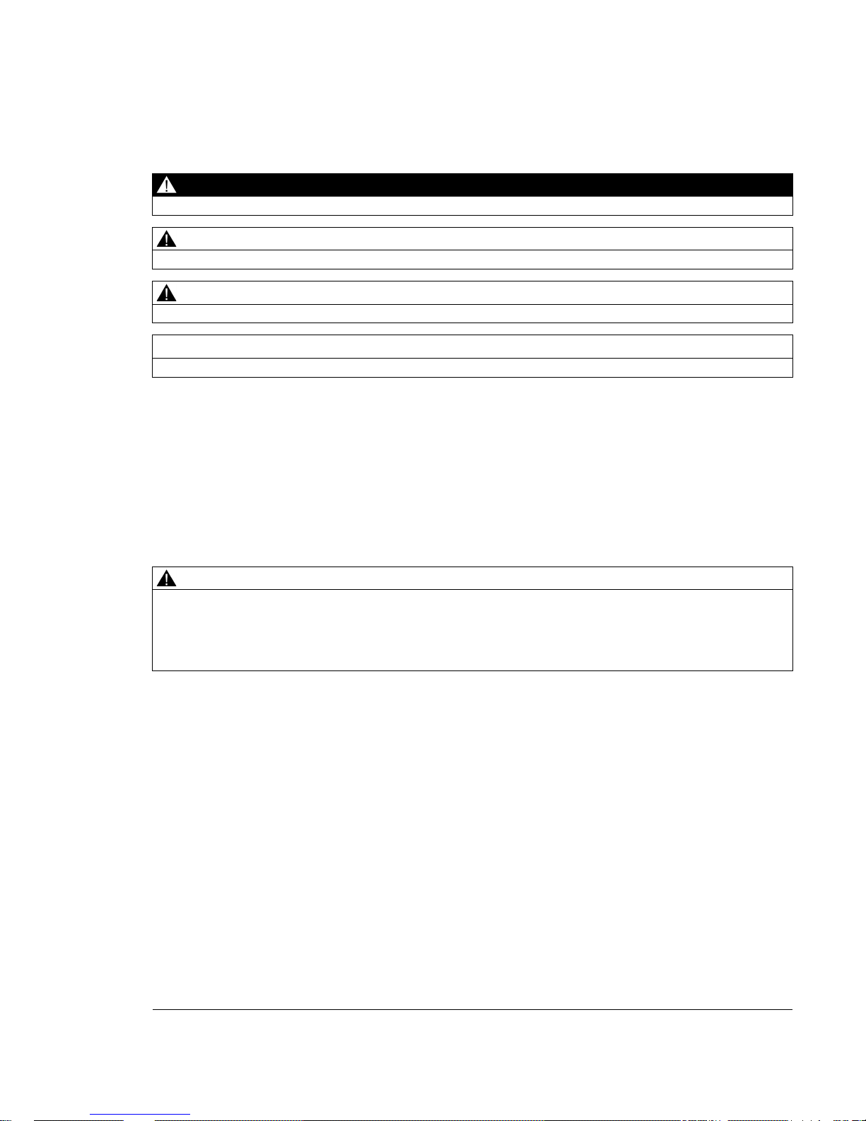
Warning notice system
This manual contains notices you have to observe in order to ensure your personal safety, as well as to prevent
damage to property. The notices referring to your personal safety are highlighted in the manual by a safety alert
symbol, notices referring only to property damage have no safety alert symbol. These notices shown below are
graded according to the degree of danger.
DANGER
indicates that death or severe personal injury will result if proper precautions are not taken.
WARNING
indicates that death or severe personal injury may result if proper precautions are not taken.
CAUTION
indicates that minor personal injury can result if proper precautions are not taken.
NOTICE
indicates that property damage can result if proper precautions are not taken.
If more than one degree of danger is present, the warning notice representing the highest degree of danger will
be used. A notice warning of injury to persons with a safety alert symbol may also include a warning relating to
property damage.
Qualified Personnel
The product/system described in this documentation may be operated only by
personnel qualified
for the specific
task in accordance with the relevant documentation, in particular its warning notices and safety instructions.
Qualified personnel are those who, based on their training and experience, are capable of identifying risks and
avoiding potential hazards when working with these products/systems.
Proper use of Siemens products
Note the following:
WARNING
Siemens products may only be used for the applications described in the catalog and in the relevant technical
documentation. If products and components from other manufacturers are used, these must be recommended
or approved by Siemens. Proper transport, storage, installation, assembly, commissioning, operation and
maintenance are required to ensure that the products operate safely and without any problems. The permissible
ambient conditions must be complied with. The information in the relevant documentation must be observed.
Trademarks
All names identified by ® are registered trademarks of Siemens AG. The remaining trademarks in this publication
may be trademarks whose use by third parties for their own purposes could violate the rights of the owner.
Disclaimer of Liability
We have reviewed the contents of this publication to ensure consistency with the hardware and software
described. Since variance cannot be precluded entirely, we cannot guarantee full consistency. However, the
information in this publication is reviewed regularly and any necessary corrections are included in subsequent
editions.
Page 3

SCALANCE X-200
Operating Instructions, 03/2015, C79000-G8976-C284-06
3
Preface
Components of the product
The following components are supplied with a
SCALANCE X-200
IE switch:
● One device
● One 2-pin plug-in terminal block
● One 4-pin plug-in terminal block
● One DVD (configuration manual, operating instructions, Primary Setup Tool, GSD file,
SNMP OPC profile)
The following components are supplied with a
SCALANCE X-200
IE switch with the
PRO
supplement:
● One device
● Protective caps for the data interfaces
● Protective caps for the connectors of the power supply
● One protective cap for the signaling contact
● One DVD (configuration manual, operating instructions, Primary Setup Tool, GSD file,
SNMP OPC profile)
Unpacking, checking
WARNING
Do not use any parts that show evidence of damage. If you use damaged parts, there is no
guarantee that the device will function according to the specification.
If you use damaged parts, this can lead to the following problems:
• Injury to persons
• Loss of the approvals
• Violation of the EMC regulations
Use only undamaged parts.
1. Make sure that the package is complete.
2. Check all the parts for transport damage.
If the consignment is incomplete or damaged, contact your supplier or your local Siemens
office.
Page 4

Preface
SCALANCE X-200
4 Operating Instructions, 03/2015, C79000-G8976-C284-06
Purpose of the Operating Instructions
These operating instructions support you when commissioning networks with the devices of
the product line SCALANCE X-200.
Overview of the technical documentation of the IE Switches X-200
The technical documentation of the X-200 product line is divided into hardware and software
and can be found in the following documents:
●
PH SCALANCE X-200 configuration manual
Software description of the X-200 product line
●
SCALANCE X-200 BA Operating Instructions
Hardware description for all product groups and general information.
You will find the documents here:
● On the data medium that ships with some products:
– Product CD / product DVD
– SIMATIC NET Manual Collection
● On the Internet pages of Siemens Industry Online Support
(http://support.automation.siemens.com/WW/view/en/33118791/133300
).
Validity of the Operating Instructions
These operating instructions are valid for the following devices:
SCALANCE X200 and SCALANCE XF200
Product name:
Order number:
X204-2 6GK5 204-2BB10-2AA3
X204-2TS
6GK5 204-2BB10-2CA2
X204-2FM
6GK5 204-2BB11-2AA3
X204-2LD
6GK5 204-2BC10-2AA3
X204-2LD TS
6GK5 204-2BC10-2CA2
X206-1
6GK5 206-1BB10-2AA3
X206-1LD
6GK5 206-1BC10-2AA3
X208
6GK5 208-0BA10-2AA3
X208PRO
6GK5 208-0HA10-2AA6
X212-2
6GK5 212-2BB00-2AA3
X212-2LD
6GK5 212-2BC00-2AA3
X216
6GK5 216-0BA00-2AA3
X224
6GK5 224-0BA00-2AA3
Flat design:
XF204
6GK5 204-0BA00-2AF2
XF204-2
6GK5 204-2BC00-2AF2
Page 5

Preface
SCALANCE X-200
Operating Instructions, 03/2015, C79000-G8976-C284-06
5
SCALANCE X200 and SCALANCE XF200
XF206-1
6GK5 206-1BC00-2AF2
XF208 6GK5 208-0BA00-2AF2
SCALANCE X200IRT and XF200IRT
Product name:
Order number:
X200-4P IRT 6GK5 200-4AH00-2BA3
X201-3P IRT
6GK5 201-3BH00-2BA3
X201-3P IRT PRO
6GK5 201-3JR00-2BA6
X202-2IRT
6GK5 202-2BB00-2BA3
X202-2P IRT
6GK5 202-2BH00-2BA3
X202-2P IRT PRO
6GK5 202-2JR00-2BA6
X204IRT
6GK5 204-0BA00-2BA3
X204IRT PRO
6GK5 204-0JA00-2BA6
Flat design:
XF204IRT
6GK5 204-0BA00-2BF2
Purpose
The SCALANCE X-200 devices are switches for setting up Ethernet networks for industrial
applications.
Restricted area of application according to Hazardous Locations (HazLoc)
The devices are only suitable for use in the following areas:
● In areas according to Class I, Division 2, Groups A, B, C and D and in areas without
explosive atmospheres.
● In areas according to Class I, Zone 2 Groups IIC and in areas without explosive
atmospheres.
Names of the devices in these operating instructions
Unless mentioned otherwise, the descriptions in these operating instructions refer to all
devices of the SCALANCE X-200 product line named above in the section on Validity.
In the remainder of the instructions, these will also be referred to as
IE switches
or also
simply as
X-200
.
Page 6

Preface
SCALANCE X-200
6 Operating Instructions, 03/2015, C79000-G8976-C284-06
Further documentation
In the system manuals "Industrial Ethernet / PROFINET Industrial Ethernet" and "Industrial
Ethernet / PROFINET passive network components", you will find information on other
SIMATIC NET products that you can operate along with the devices of this product line in an
Industrial Ethernet network.
You will find the system manuals on the Internet pages of Siemens Industry Online Support
under the following entry IDs:
● 27069465 (http://support.automation.siemens.com/WW/view/en/27069465
)
Industrial Ethernet / PROFINET Industrial Ethernet System Manual
● 84922825 (http://support.automation.siemens.com/WW/view/en/84922825)
Industrial Ethernet / PROFINET - Passive network components System Manual
Finding information
To help orientation, there is not only a table of contents but also an Index in the Appendix.
The SIMATIC NET Glossary also provides additional help, see below.
Audience
These operating instructions are intended for persons involved in commissioning networks in
which IE switches are used.
SIMATIC NET Selection Tool
The SIMATIC NET selection tool supports you when selecting Industrial Ethernet switches
and components for Industrial Wireless Communication. You will find current information on
the Product Support pages under the following entry ID:
39134641 (http://support.automation.siemens.com/WW/view/en/39134641
)
Page 7

Preface
SCALANCE X-200
Operating Instructions, 03/2015, C79000-G8976-C284-06
7
Where to find Siemens documentation
● Article numbers
You will find the article numbers for the Siemens products of relevance here in the
following catalogs:
– SIMATIC NET - Industrial Communication / Industrial Identification, catalog IK PI
– SIMATIC - Products for Totally Integrated Automation and Micro Automation, catalog
ST 70
You can request the catalogs and additional information from your Siemens
representative. You will also find the product information in the Siemens Industry Mall at
the following address:
(https://mall.industry.siemens.com
)
● Manuals on the Internet
You will find SIMATIC NET manuals on the Internet pages of Siemens Industry Online
Support:
Link to Customer Support (http://support.automation.siemens.com/WW/view/en
)
Enter the entry ID of the relevant manual as the search item. The entry ID is specified in
the references.
As an alternative, you will find the SIMATIC NET documentation on the pages of Product
Support:
10805878 (http://support.automation.siemens.com/WW/view/en/10805878
)
Go to the required product group and make the following settings:
"Entry list" tab, Entry type "Manuals / Operating Instructions"
● Manuals on the data medium
You will often find manuals of SIMATIC NET products on the data medium that ships with
many of the SIMATIC NET products.
Security information
Siemens provides products and solutions with industrial security functions that support the
secure operation of plants, solutions, machines, equipment and/or networks. They are
important components in a holistic industrial security concept. With this in mind, Siemens’
products and solutions undergo continuous development. Siemens recommends strongly
that you regularly check for product updates.
For the secure operation of Siemens products and solutions, it is necessary to take suitable
preventive action (e.g. cell protection concept) and integrate each component into a holistic,
state-of-the-art industrial security concept. Third-party products that may be in use should
also be considered. For more information about industrial security, visit
http://www.siemens.com/industrialsecurity.
To stay informed about product updates as they occur, sign up for a product-specific
newsletter. For more information, visit http://support.automation.siemens.com.
Page 8

Preface
SCALANCE X-200
8 Operating Instructions, 03/2015, C79000-G8976-C284-06
SIMATIC NET glossary
Explanations of many of the specialist terms used in this documentation can be found in the
SIMATIC NET glossary.
You will find the SIMATIC NET glossary here:
● SIMATIC NET Manual Collection or product DVD
The DVD ships with certain SIMATIC NET products.
● On the Internet under the following entry ID:
50305045 (http://support.automation.siemens.com/WW/view/en/50305045
)
Trademarks
The following and possibly other names not identified by the registered trademark sign ® are
registered trademarks of Siemens AG:
SIMATIC NET, SCALANCE, C-PLUG, OLM
Page 9

SCALANCE X-200
Operating Instructions, 03/2015, C79000-G8976-C284-06
9
Table of contents
Preface ...................................................................................................................................................... 3
1 Functions ................................................................................................................................................. 11
2 Description of the device ......................................................................................................................... 15
2.1 Device views ........................................................................................................................... 15
2.2 The LEDs ................................................................................................................................ 17
2.2.1 LED display when the device starts up ................................................................................... 17
2.2.2 Power LED "L" (green/yellow LED) ........................................................................................ 17
2.2.3 Fault LED "F" (yellow/red LED) .............................................................................................. 18
2.2.4 Redundancy manager LED "RM" (green LED) ...................................................................... 18
2.2.5 Standby LED "RM" (yellow LED) ............................................................................................ 19
2.2.6 Port LEDs "P" (green/yellow LEDs) ........................................................................................ 20
2.2.7 Diagnostics LEDs for optical connectors "F" (yellow LED) ..................................................... 20
2.2.8 Show Location ........................................................................................................................ 20
2.3 The SET button ....................................................................................................................... 21
2.4 The C-PLUG ........................................................................................................................... 22
3 Safety notices .......................................................................................................................................... 27
3.1 Safety notices in general ........................................................................................................ 27
3.2 Safety notices for hazardous areas ........................................................................................ 29
3.3 Security recommendations ..................................................................................................... 30
4 Installation ............................................................................................................................................... 33
4.1 Safety notices for installation .................................................................................................. 33
4.2 Installation options .................................................................................................................. 36
4.3 Installation on a DIN rail .......................................................................................................... 37
4.4 Installation on a standard rail .................................................................................................. 38
4.5 Wall mounting ......................................................................................................................... 39
5 Connecting up ......................................................................................................................................... 41
5.1 Safety when connecting up ..................................................................................................... 41
5.2 Power supply .......................................................................................................................... 44
5.2.1 Power supply via terminal block ............................................................................................. 44
5.2.2 Supply for X208PRO .............................................................................................................. 45
5.2.3 Supply for IRT-PRO devices ................................................................................................... 45
5.3 Grounding ............................................................................................................................... 48
5.4 Signaling contact ..................................................................................................................... 49
5.5 Attachment to Industrial Ethernet ........................................................................................... 51
5.5.1 Electrical connections ............................................................................................................. 51
Page 10

Table of contents
SCALANCE X-200
10 Operating Instructions, 03/2015, C79000-G8976-C284-06
5.5.1.1 Electrical attachments to Industrial Ethernet ......................................................................... 51
5.5.1.2 Electrical connectors of the X208PRO .................................................................................. 53
5.5.2 Optical attachments to Industrial Ethernet ............................................................................. 55
5.5.2.1 Multimode fiber-optic cable .................................................................................................... 55
5.5.2.2 Single mode fiber-optic cable ................................................................................................. 56
5.5.2.3 POF and PCF cables ............................................................................................................. 56
5.5.3 Push-pull connector for IRT-PRO devices ............................................................................. 58
6 Approvals ................................................................................................................................................. 59
7 Technical specifications ........................................................................................................................... 67
A Dimension drawings ................................................................................................................................ 77
B Test of mechanical stability ...................................................................................................................... 83
C Training, Service & Support ..................................................................................................................... 85
Index ........................................................................................................................................................ 87
Page 11

SCALANCE X-200
Operating Instructions, 03/2015, C79000-G8976-C284-06
11
1
Functions of the X-200 IE Switches
The X-200 IE switches are ideally suited for setting up Industrial Ethernet networks in bus,
star and ring structures with transmission rates of 10/100 Mbps. All X-200 switches operate
in the SIMATIC environment.
Hardware properties:
● X devices have a rugged metal housing and can be installed on a DIN rail, a standard rail
or directly on a wall.
● XF devices have a plastic housing and a flat design. They are suitable for installation on a
DIN rail.
● Redundant power supply, 2 x 24 VDC (exception: IRT-PRO devices)
● Diagnostics LED
● Signaling contact
● SET button for local configuration of the signaling contact
● Slot for C-PLUG
● Reliable plug-in connections thanks to rugged device connectors suitable for industry in
conjunction with PROFINET-compliant FastConnect plugs.
● TS devices meet the railway standard EN 50155
Software properties:
● PROFINET Diagnostics
● Topology support (LLDP)
● CLI - Command Line Interface / Telnet
● WBM - Web Based Management
● Configuration with STEP 7
● SNMP
● Ring redundancy including redundancy manager
● Passive Listening
● FM devices support the Fiber Monitoring Protocol and allow the monitoring of optical line
sections.
Page 12

Functions
SCALANCE X-200
12 Operating Instructions, 03/2015, C79000-G8976-C284-06
Special features of the X-200IRT IE switches
The IRT variants were designed specifically for setting up Industrial Ethernet networks with
isochronous/clock synchronous real-time communication. In addition to the properties named
above, the IRT switches also provide the following functions:
● IRT communication based on the combination of the switching methods cut through and
store and forward.
● Fast media redundancy thanks to an integrated redundancy manager for Fast Ethernet.
● Standby redundancy
Special features of the PRO variants
The devices with the "PRO" supplement are designed with degree of protection IP65/IP67
for use outside a cabinet.
Frame delay times
The number of IE Switches X-200 connected in a line influences the frame delay.
Note
Frame delay time with X-200 without IRT
When a frame passes through X
-200 IE switches, it is delayed by the Store&Forward
fun
ction of the X-200 IE switches.
•
With a 64 byte frame length by approx. 10 microseconds (at 100 Mbps).
•
With a 1500 byte frame length by approx. 130 microseconds (at 100 Mbps).
This means that the more IE
Switch X-200 devices the frame passes through, the longer the
frame delay.
Note
Frame delay time with X-200 with IRT
The more X
-200IRT IE switches a frame runs through, the higher the frame delay. By using
the "cut through" switching mechanism, the X
-200IRT IE switches are ideal to meet the real-
time requirements of PROFINET.
Cut through is, however, not possible:
•
Between a port set to 10 Mbps and a port set to 100 Mbps.
•
When two packets are to be sent at the same time on one port.
In this case, an X-200 IE switch changes to Store&Forward and the delay increases.
Page 13
Functions
SCALANCE X-200
Operating Instructions, 03/2015, C79000-G8976-C284-06
13
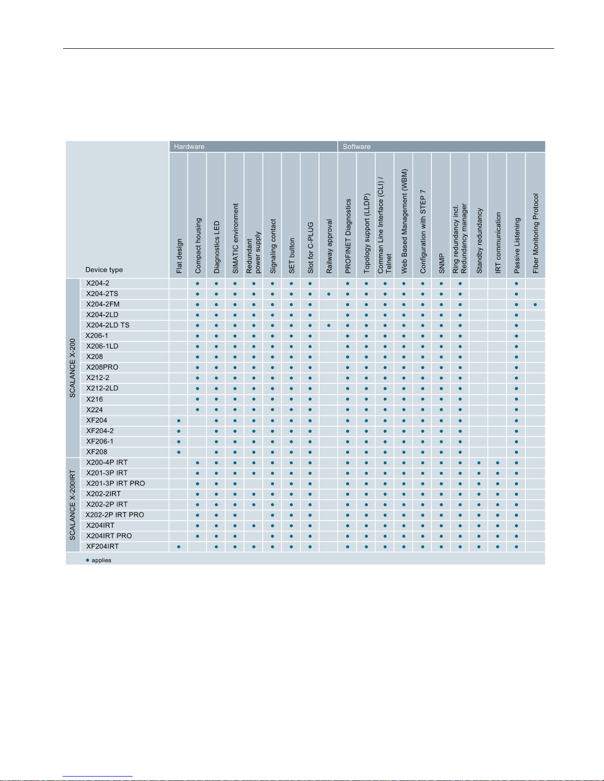
Overview of the functions
The following table shows the hardware and software properties for each product variant of
the X-200 switches in detail:
Number of electrical and optical connectors in the product name
The number before the hyphen in the product name indicates the number of electrical
connectors. The number following the hyphen indicates the number of optical connectors of
the device. For example, the switch X212-2 has twelve electrical and two optical connectors.
Page 14

Functions
SCALANCE X-200
14 Operating Instructions, 03/2015, C79000-G8976-C284-06
Page 15
SCALANCE X-200
Operating Instructions, 03/2015, C79000-G8976-C284-06
15
2
2.1
Device views
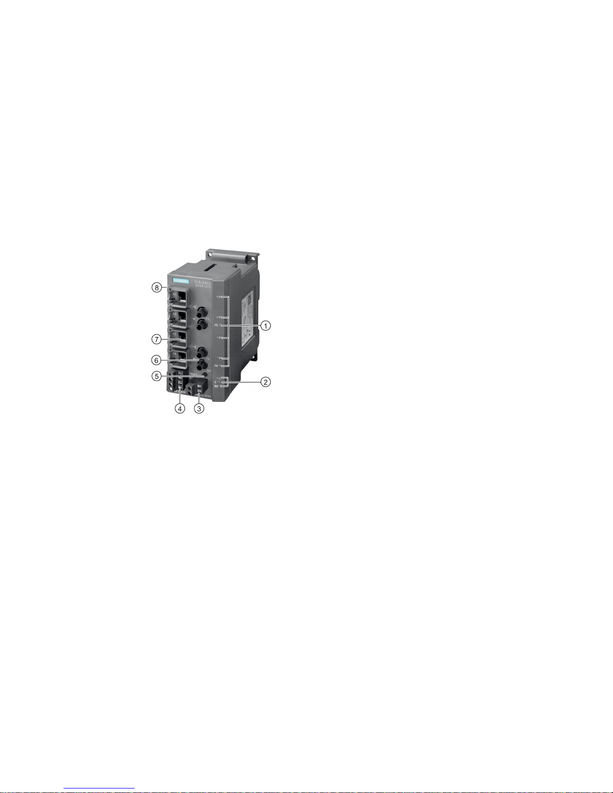
Device view based on the example of an X204-2TS
The following figure describes the individual components of an IE switch X200.
1
LEDs for attachments to Industrial Ethernet
2 LEDs
•
L: Power LED, power supply
•
F: Fault LED
•
RM: Redundancy manager or standby
3
Connector for signaling contact
4
Connector for power supply
5
SET button
6
Optical attachment to Industrial Ethernet
7
Electrical attachment to Industrial Ethernet
8 (on rear of device, not shown in figure:) Slot for C
-
PLUG
Page 16
Description of the device
2.1 Device views
SCALANCE X-200
16 Operating Instructions, 03/2015, C79000-G8976-C284-06
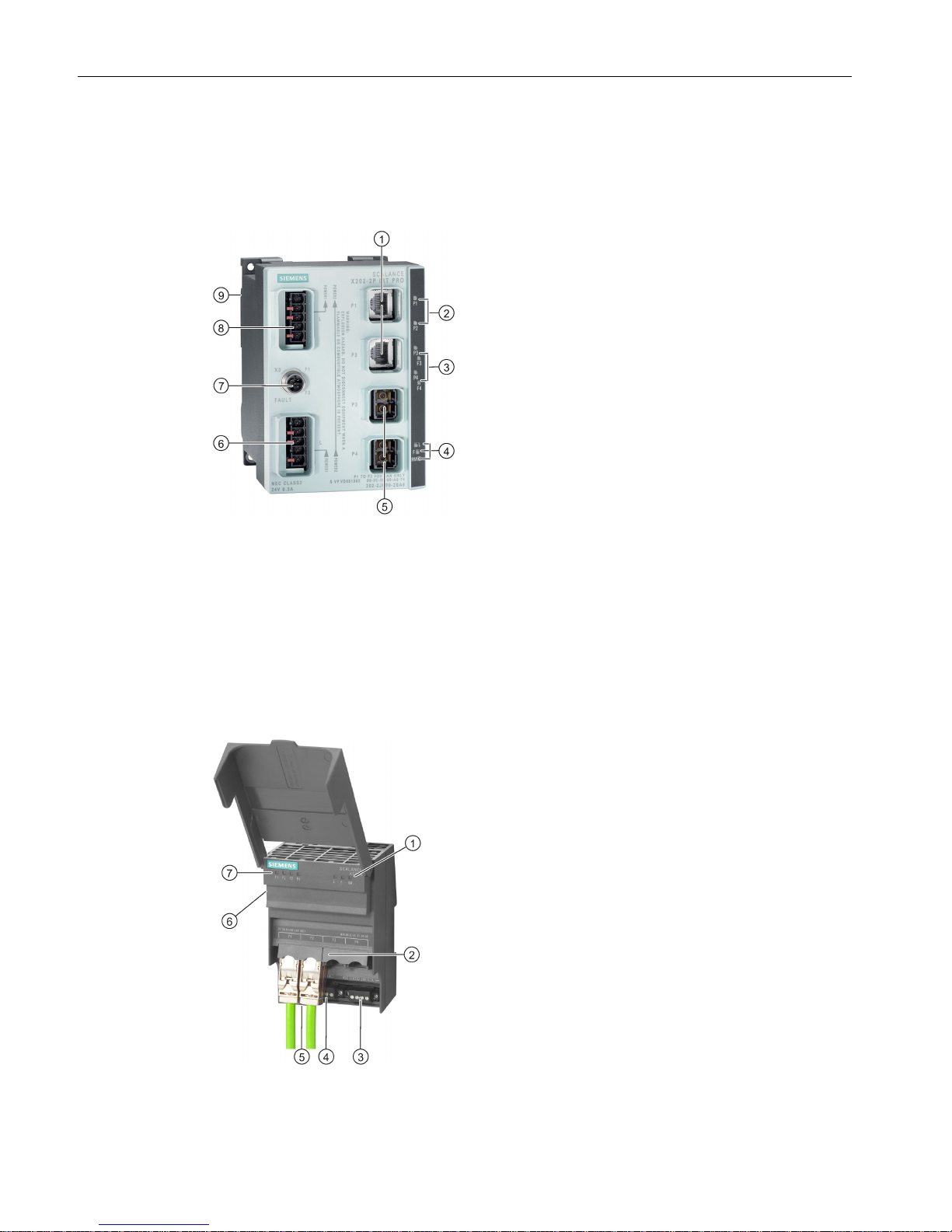
Device view based on the example of an X202-2P IRT PRO
The following figure describes the individual components of a PRO version of an IE switch X-
200.
1
Electrical attachments to Industrial Ethernet
2 LEDs for electrical connectors
3 LEDs for optical connectors with diagnostics
LEDs
4 LEDs
•
L: Power LED, power supply
•
F: Fault LED
•
RM:
– green = redundancy manager
– yellow = standby indicator
5
Optical attachments to Industrial Ethernet
6 Connector for the power supply (supplied with
L1, additionally looped through to L2)
7
Connector for signaling contact
8 Power supply for further devices (looped
through from L1 to L2)
9 (on rear of device, not shown in figure): Slot for
the C-PLUG and SET button
Device view based on the example of an XF204
The following figure describes the individual components of an IE switch X-200, flat design.
1 LEDs
•
L: Power LED, power supply
•
F: Fault LED
•
RM: Redundancy manager
2
Attachments to Industrial Ethernet
3
Connector for power supply
4
Connector for signaling contact
5 (behind the connectors, not shown in figure:)
SET button
6 (on side of device, not shown in figure:) Slot for
C-PLUG
7 LEDs for attachments to Industrial Ethernet
Page 17

Description of the device
2.2 The LEDs
SCALANCE X-200
Operating Instructions, 03/2015, C79000-G8976-C284-06
17
2.2
The LEDs
2.2.1
LED display when the device starts up
When the X-200 starts up, the LEDs light up in the following sequence:
● The green power LED lights up immediately after turning on the device.
● The LEDs of the Ethernet connectors light up for approximately 6 seconds.
● When the Ethernet LEDs go off, the red fault LED is lit for approximately 20 seconds.
● Following this, after approximately 2 seconds the correct link status is displayed.
The X-200 is now ready for operation.
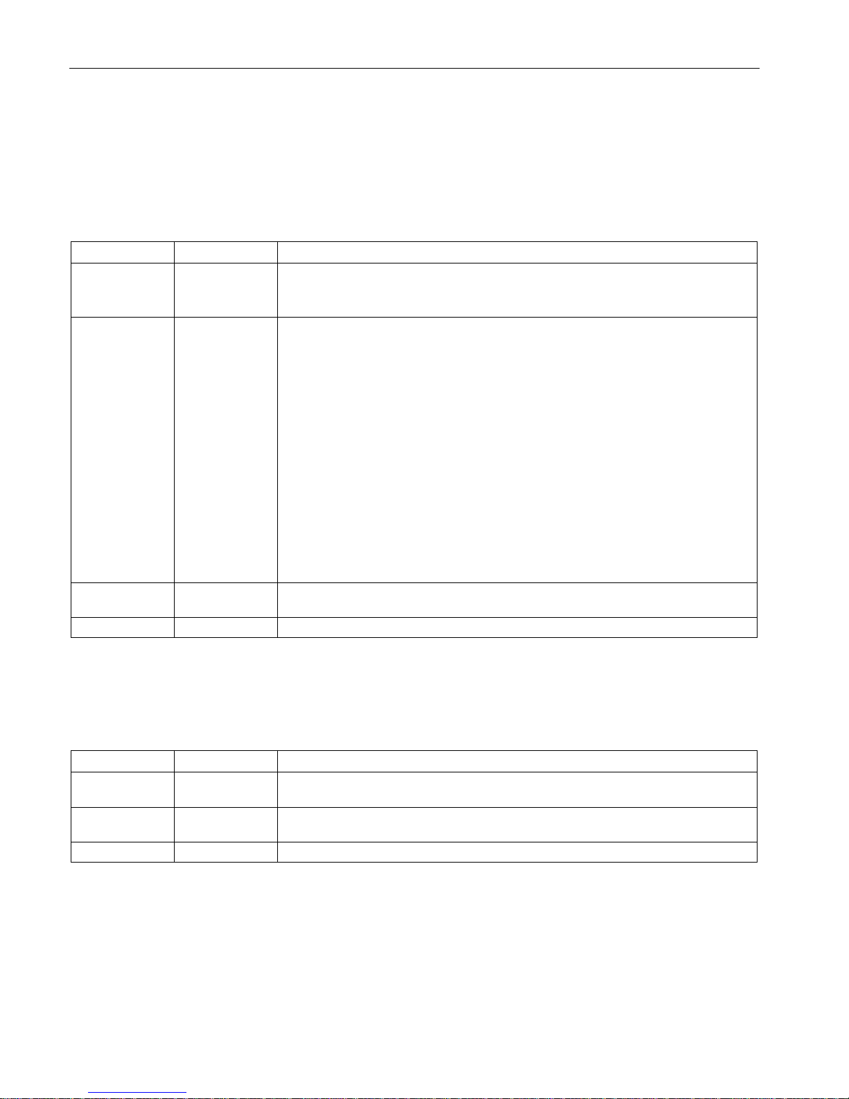
2.2.2
Power LED "L" (green/yellow LED)
The power LED shows the status of the power supply on the X-200 IE switch. The power
LED can light up either green or yellow. The meanings of the display are as follows:
LED color
LED status
Meaning
Green
Lit
Both power supplies are connected; in other words, redundant power supply.
Yellow Lit Only one power supply is connected.
- Off No power supply is connected or the voltage is < 14 VDC or with TS devices < 8
VDC.
Note
The following devices do not have a redundant power supply:
•
X201-3P IRT PRO
•
X202-2P IRT PRO
•
X204IRT PRO
Page 18
Description of the device
2.2 The LEDs
SCALANCE X-200
18 Operating Instructions, 03/2015, C79000-G8976-C284-06
2.2.3
Fault LED "F" (yellow/red LED)
The fault LED indicates a fault/error on the X-200. If the X-200 detects an error, the signaling
contact is opened at the same time assuming that the response of the signaling contact was
not configured differently.
The meanings of the fault LED display are as follows:
LED color
LED status
Meaning
Yellow Lit The LED can only adopt this status with FM devices.
Check the received power or the loss of power on optical connections. If necessary,
replace the parts.
Red Lit The fault LED lighting up can have the following meanings:
• Link down event on a monitored port
• Loss of the power supply
• C-PLUG error
• Device is in PROFINET mode:
– There is no connection to the controller.
– There is a connection to the controller. A configured diagnostics interrupt is
also pending, for example power fail interrupt, C-PLUG interrupt etc.
• Redundancy manager connected through
• Switchover of standby connection
• A defined value was undershot in a monitored optical connection.
• A loop was detected.
• Device startup. The LED lights up for approximately 20 seconds.
Red Flashing Internal error detected. Notify maintenance personnel. If necessary, send the device
in for repair.
-
Off
No error detected.
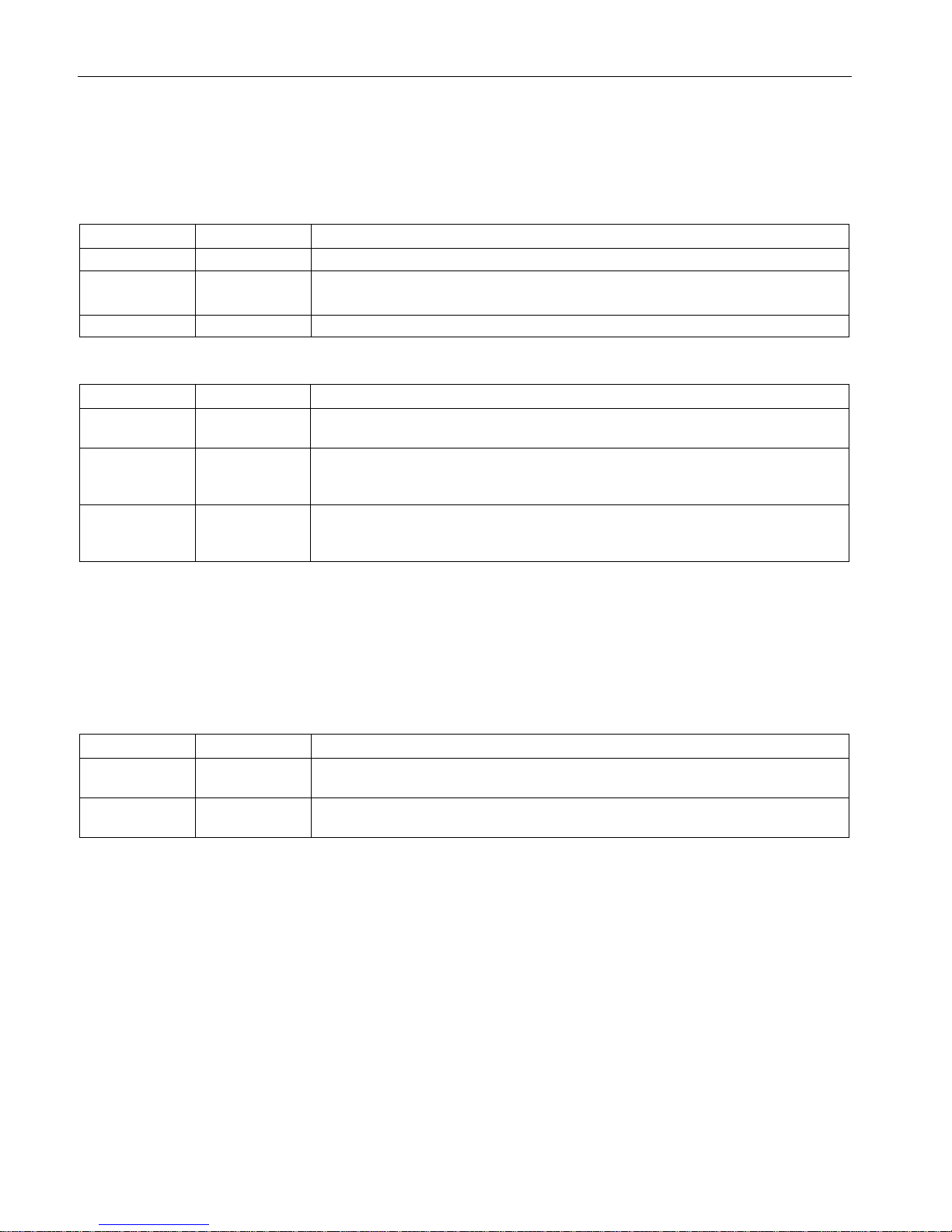
2.2.4
Redundancy manager LED "RM" (green LED)
The green LED shows the following statuses of the X-200:
LED color
LED status
Meaning
Green Lit The device is operating in the role of redundancy manager. The ring is operating free
of errors. The monitoring is enabled.
Green Flashing The device is operating in the role of redundancy manager. An interruption was de-
tected in the ring. The device has switched through.
-
Off
The device is not operating in the role of redundancy manager.
Page 19

Description of the device
2.2 The LEDs
SCALANCE X-200
Operating Instructions, 03/2015, C79000-G8976-C284-06
19
Note
This LED labeled on the device with "RM" has a dual function. The color of the display
changes depending on the function:
•
If the LED is lit green, the redundancy manager function is indicated.
•
If the LED is lit yellow, the standby function is indicated.
In
Web Based Management (WBM), the LED is labeled differently depending on the
function:
•
The redundancy manager function (as shipped) is labeled "RM".
•
The standby function is labeled "SB" in the WBM.
2.2.5
Standby LED "RM" (yellow LED)
You will find the standby LED only on devices with the IRT function.
Note
This LED labeled on the device with "RM" has a dual function. The color of the display
changes depending on the function:
•
If the LED is lit green, the redundancy manager function is indicated.
•
If the LED is lit yellow, the standby function is indicated.
In
Web Based Management (WBM), the LED is labeled differently depending on the
function:
•
The redundancy manager function (as shipped) is labeled "RM".
•
The standby function is labeled "SB" in the WBM.
The yellow LED indicates the following statuses of the X-200IRT:
LED color
LED status
Meaning
Yellow
Lit
The standby function is activated, the switch is in active mode.
Yellow
Flashes slowly
The standby function is activated, the switch is in passive mode.
Yellow
Flashes quickly
Standby partner lost.
-
Off
The standby function is not activated.
Page 20
Description of the device
2.2 The LEDs
SCALANCE X-200
20 Operating Instructions, 03/2015, C79000-G8976-C284-06
2.2.6
Port LEDs "P" (green/yellow LEDs)
The LEDs of the Ethernet connectors can be lit green or yellow. The meanings of the display
are as follows:
LED color
LED status
Meaning
Green
Lit
Link exists, no data reception
Yellow Lit Link exists, data being received
Device startup. The LED lights up for approximately 6 seconds.
Yellow
Flashing
Setting or display of the fault mask
The following statuses of the port LEDs do not exist on devices with the IRT function:
LED color
LED status
Meaning
Green flashes
once per period
Link exists and port in "blocking" status.
In this status, the port only receives management data (no user data).
Green flashes
three times per
period
Link exists and port is deactivated by the management.
In this status, no data is sent or received via the port.
Green flashes
four times per
period
Port exists and is in the "monitor port" status.
In this status, the data traffic of another port is mirrored to this port.
2.2.7
Diagnostics LEDs for optical connectors "F" (yellow LED)
You will find the diagnostics LEDs only on the devices with the IRT function.
The status of the optical connectors is indicated by an additional yellow LED per connector.
The LEDs signal the following statuses:
LED color
LED status
Meaning
Yellow Lit Check the plug-in connection and the quality of the fiber-optic cable. If necessary,
replace the parts.
- Off Relevant only if the link exists. The existing link power margin is adequate for error-
free operation.
2.2.8
Show Location
Localizing an IE Switches X-200
To identify an IE Switch X-200 locally and with certainty, you can use the "show location"
function on a programming device to select the node over the network and make it flash.
This can be used, for example, when assigning addresses to make sure that the correct
node receives the address. All port LEDs of the addressed node flash green at 2 Hz.
With the Primary Setup Tool (PST) V3.0 or higher, you can trigger this function with "Module
\ Flash".
Page 21
Description of the device
2.3 The SET button
SCALANCE X-200
Operating Instructions, 03/2015, C79000-G8976-C284-06
21
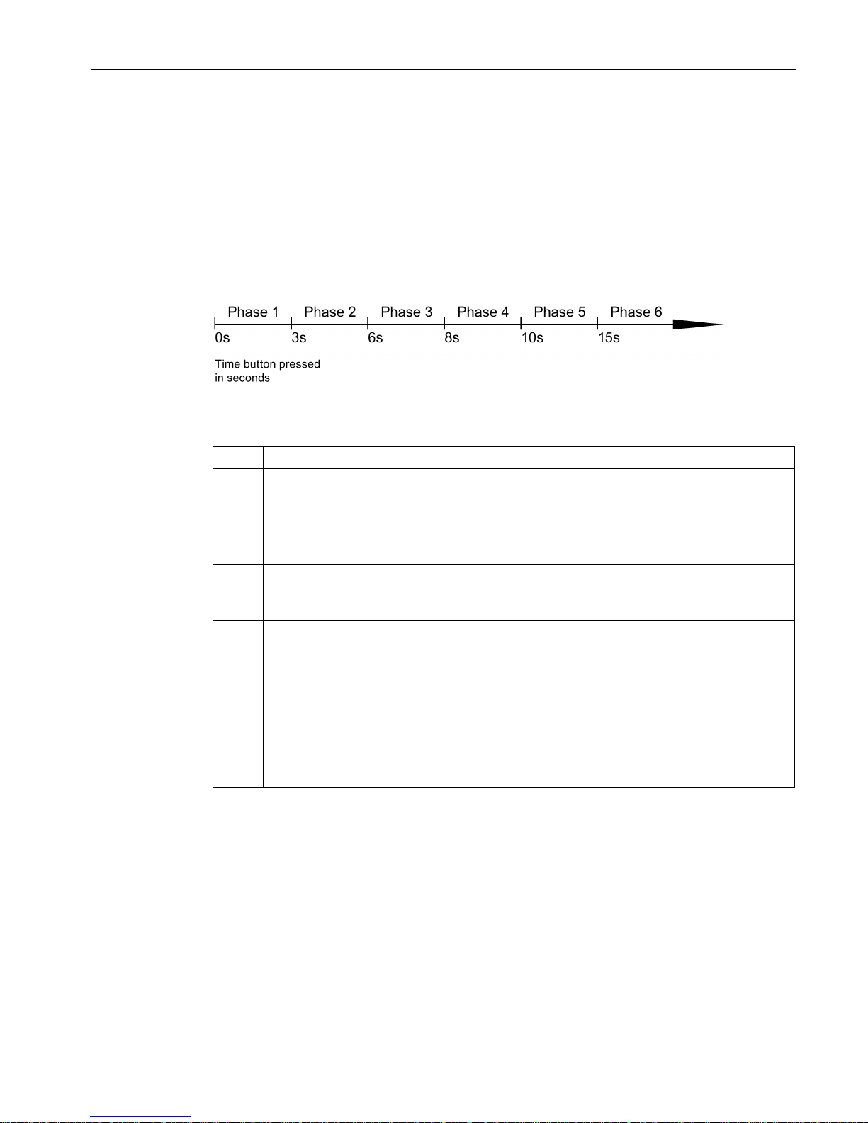
2.3
The SET button
Function of the SET button
With the SET button, you can change various settings of the device. The changed settings
remain after cycling power to the device.
Different settings are made depending on how long you hold down the SET button, as
described in the following table:
Figure 2-1 Phases for changing settings using the SET button
Phase
Description
1 The currently set fault mask is displayed. If no fault mask has been set, all ports flash one
after the other.
If you release the button in phase 1, this has no effect.
2 The LEDs of the ports at which there is currently a link flash at 2.5 Hz.
If you release the button in phase 2, this has no effect.
3 The LEDs of the ports at which there is currently a link and the LEDs of the connected pow-
er supply are lit permanently.
If you release the button in phase 3, the fault mask corresponding to the lit LEDs is adopted.
4 The RM LED flashes.
If you release the button in phase 4, the redundancy manager is deactivated. The redundancy function remains enabled. The device changes to "Automatic Redundancy Detect"
mode.
5 The RM LED is lit permanently.
If you release the button in phase 5, the redundancy function is activated and the device is
configured as HRP manager.
6 All LEDs flash.
The device is reset to the factory defaults.
Page 22

Description of the device
2.4 The C-PLUG
SCALANCE X-200
22 Operating Instructions, 03/2015, C79000-G8976-C284-06
2.4
The C-PLUG
Area of application
The C-PLUG is an exchangeable medium for storage of the configuration and project
engineering data of the basic device. This means that the configuration data remains
available if the basic device is replaced.
How it works
Power is supplied by the basic device. The C-PLUG retains all data permanently when the
power is turned off.
If an empty C-PLUG (factory settings) is inserted, all configuration data of an IE
Switch X-200 is saved to it when the device starts up. Changes to the configuration during
operation are also saved on the C-PLUG without any operator intervention being necessary.
If a C-PLUG is inserted, the configuration stored internally on the basic device is no longer
changed. Al changes made to the configuration during ongoing operation are only stored on
the C-PLUG.
A basic device with an inserted C-PLUG automatically uses the configuration data of the
C-PLUG when it starts up. This is, however, only possible when the data was written by a
compatible device type.
This allows fast and simple replacement of the basic device. If a device is replaced, the CPLUG is taken from the failed component and inserted in the replacement device. The first
time it is started up, the replacement device has the same configuration as the failed device
except for the MAC address set by the vendor.
Page 23
Description of the device
2.4 The C-PLUG
SCALANCE X-200
Operating Instructions, 03/2015, C79000-G8976-C284-06
23
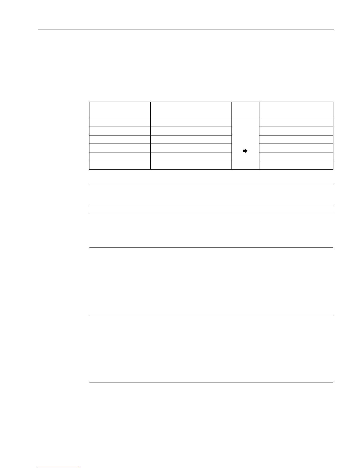
Compatible devices
As a general rule, the data on the C-PLUG is only compatible with devices having an
identical order number and the same device name.
The device combinations shown in the following table are exceptions. With these devices,
the exchange of the C-PLUG is possible in one direction.
Device type
C-PLUG created by device with
order number
Compatible with device with
order number
X204-2
6GK5 204-2BB00-2AA3
6GK5 204-2BB10-2AA3
X204-2LD 6GK5 204-2BC00-2AA3 6GK5 204-2BC10-2AA3
X206-1
6GK5 206-1BB00-2AA3
6GK5 206-1BB10-2AA3
X206-1LD
6GK5 206-1BC00-2AA3
6GK5 206-1BC10-2AA3
X208
6GK5 208-0BA00-2AA3
6GK5 208-0BA10-2AA3
X208PRO
6GK5 208-0HA00-2AA6
6GK5 208-0HA10-2AA6
Note
Combinations other than those shown in the table are not compatible with each other.
Note
If you insert a C
-PLUG in a compatible device, the system name of the original device is
entered both in the system name as well as in the PROFINET IO device name of the
compatible device.
Using a previously written C-PLUG
If you want to insert a C-PLUG that has already been used and written to into a new
differently configured X-200 IE switch, you will first need to delete the existing data on the CPLUG. You will find information about this in the configuration manual of the SCALANCE X200 in the section on the WBM menu items.
Note
The X
-200 IE switches normally start up with the configuration of the C-
PLUG, assuming this
was written to by a compatible device type. If the C
-PLUG was written to by an incompatible
device type, the basic device will not start up fully and signals an error. The WBM menu
"System C
-PLUG" is displayed automatically. Here, use the "Modify C-PLUG" function to
specify whether or not the device operates
with a C-PLUG.
If you operate a device with a C
-PLUG, the C-PLUG can either be initialized with the factory
settings or with the settings stored internally on the device.
Page 24
Description of the device
2.4 The C-PLUG
SCALANCE X-200
24 Operating Instructions, 03/2015, C79000-G8976-C284-06
Diagnostics
The following events are signaled by the diagnostics mechanisms of the X-200, such as
LEDs, WBM etc.:
● Inserting a C-PLUG that contains the configuration of an incompatible device type.
● The accidental removal of a C-PLUG
● General malfunctions of the C-PLUG.
The C-PLUG does not ship with the product
The C-PLUG is not supplied with the X-200 IE switch. It is an optional accessory available
under the following order number: 6GK1 900-0AB00.
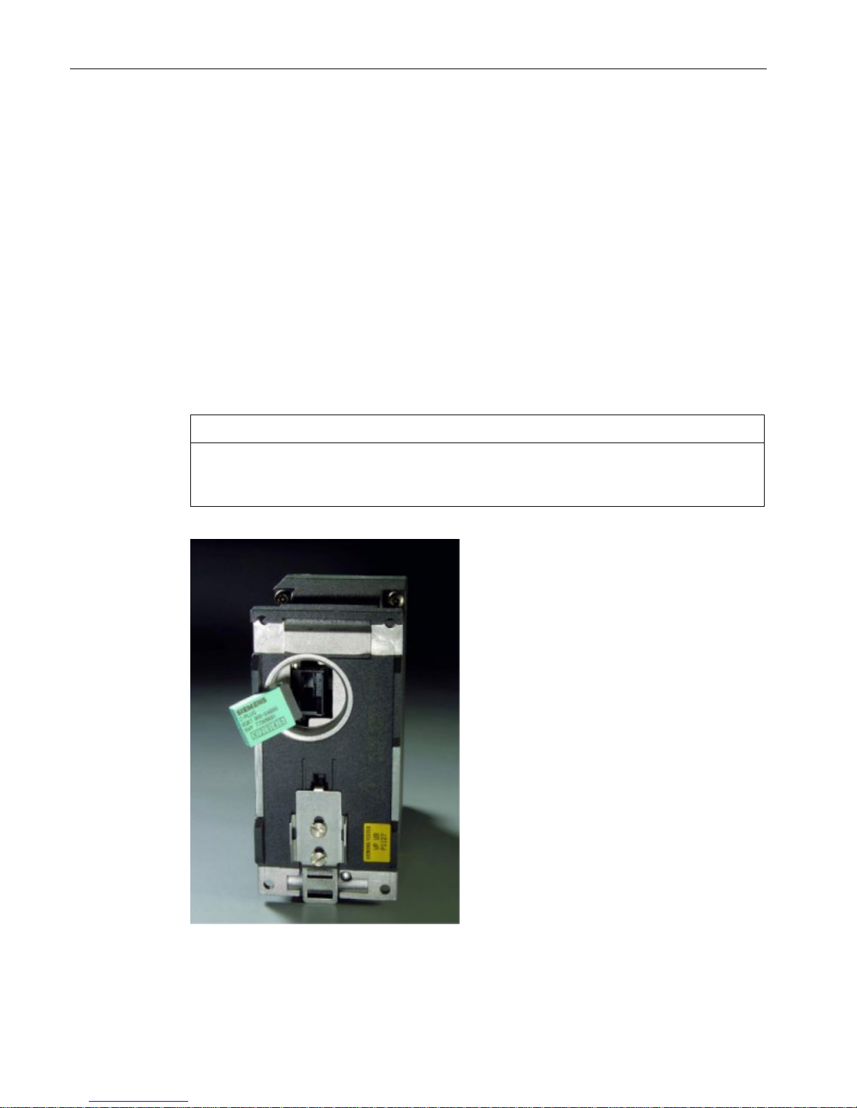
Inserting in the slot
NOTICE
•
Insert and remove the C-PLUG only when power is off.
•
In a device with a varnished printed circuit board, you may only use a C-PLUG with a
varnished board.
Figure 2-2 C-PLUG and slot
Page 25

Description of the device
2.4 The C-PLUG
SCALANCE X-200
Operating Instructions, 03/2015, C79000-G8976-C284-06
25
The slot for the C-PLUG is located as follows:
● On the IE Switch X-200 on the back of the device.
● On the IE Switch XF-200 on the left hand side of the device.
Follow the steps below to insert the C-PLUG:
1. Remove the screw cover.
2. Insert the C-PLUG in the slot.
3. Close the slot with the screw cover.
Removing the C-PLUG
It is only necessary to remove the C-PLUG if the IE Switch X-200 develops a fault.
You can lever the C-PLUG out of the slot carefully using flat pliers, tweezers, or a small
screwdriver.
If no C-PLUG is inserted in the device, when the device restarts, an error message is output
in Web Based Management and in the Command Line Interface. In this case, you will need
to set the device to operation without C-PLUG. For further information, refer to the section
"System C-PLUG" in the section on the WBM menu in the configuration manual.
Page 26

Description of the device
2.4 The C-PLUG
SCALANCE X-200
26 Operating Instructions, 03/2015, C79000-G8976-C284-06
Page 27
SCALANCE X-200
Operating Instructions, 03/2015, C79000-G8976-C284-06
27
3
3.1
Safety notices in general
Note the following safety notices. These relate to the entire working life of the device.
WARNING
Do not use any parts that show evidence of damage
If you use damaged parts, there is no guarantee that the device will function according to
the specification.
If you use damaged parts, this can lead to the following problems:
• Injury to persons
• Loss of the approvals
• Violation of the EMC regulations
• Damage to the device and other components
Use only undamaged parts.
Installation guidelines
The product meets the requirements if you adhere to the installation and safety notices
contained in this documentation and in the following documentation when installing and
operating the product.
Current documentation on the Internet
The current descriptions of the currently available products can be found on the Product
Support pages under the entry IDs below:
● Configuration manual SIMATIC NET PH SCALANCE X-200
63203259 (http://support.automation.siemens.com/WW/view/en/63203259
)
● System manual SIMATIC NET Industrial Ethernet Network Manual
27069465 (http://support.automation.siemens.com/WW/view/en/27069465
)
● Configuration manual EMC Installation Guidelines
60612658 (http://support.automation.siemens.com/WW/view/en/60612658
)
Electrostatic discharge
To protect the product process from electrostatic discharge, personnel must first discharge
any electrostatic charge from their body before touching the product.
Page 28

Safety notices
3.1 Safety notices in general
SCALANCE X-200
28 Operating Instructions, 03/2015, C79000-G8976-C284-06
Special safety notices
You should also read the safety notices relating to handling in the individual sections,
particularly in the sections "Installation" and "Connecting up".
Page 29

Safety notices
3.2 Safety notices for hazardous areas
SCALANCE X-200
Operating Instructions, 03/2015, C79000-G8976-C284-06
29
3.2
Safety notices for hazardous areas
Safety notices on use in hazardous areas
General safety notices relating to protection against explosion
WARNING
EXPLOSION HAZARD
DO NOT OPEN WHEN ENERGIZED.
Safety notices when using the device according to Hazardous Locations (HazLoc)
If you use the device under HazLoc conditions you must also keep to the following safety
notices in addition to the general safety notices for protection against explosion:
This equipment is suitable for use in Class I, Division 2, Groups A, B, C and D or nonhazardous locations only.
This equipment is suitable for use in Class I, Zone 2, Group IIC or non-hazardous locations
only.
Page 30

Safety notices
3.3 Security recommendations
SCALANCE X-200
30 Operating Instructions, 03/2015, C79000-G8976-C284-06
3.3
Security recommendations
To prevent unauthorized access, note the following security recommendations.
General
● You should make regular checks to make sure that the device meets these
recommendations and/or other security guidelines.
● Evaluate your plant as a whole in terms of security. Use a cell protection concept with
suitable products.
Physical access
● Limit physical access to the device to qualified personnel.
The memory card or the C-PLUG contains sensitive data such as certificates, keys etc.
that can be read out and modified.
● Lock unused physical ports on the device. Unused ports can be used to gain forbidden
access to the plant.
Software (security functions)
● Keep the software up to date. Check regularly for security updates of the product.
You will find information on this at: www.siemens.com/industrialsecurity
(http://www.siemens.com/industrialsecurity
)
● Only activate protocols that you really require to use the device.
● Restrict access to the device with a firewall or rules in an access control list (ACL -
Access Control List).
● The option of VLAN structuring provides good protection against DoS attacks and
unauthorized access. Check whether this is practical or useful in your environment.
● Enable logging functions. Use the central logging function to log changes and access
attempts centrally. Check the logging information regularly.
● Configure a Syslog server to forward all logs to a central location.
Passwords
● Define rules for the use of devices and assignment of passwords.
● Regularly update passwords and keys to increase security.
● Change all default passwords for users before you operate the device.
● Only use passwords with a high password strength. Avoid weak passwords for example
password1, 123456789, abcdefgh.
● Make sure that all passwords are protected and inaccessible to unauthorized personnel.
● Do not use the same password for different users and systems or after it has expired.
Page 31

Safety notices
3.3 Security recommendations
SCALANCE X-200
Operating Instructions, 03/2015, C79000-G8976-C284-06
31
Keys and certificates
This section deals with the security keys and certificates you require to set up SSL.
● We strongly recommend that you create your own SSL certificates and make them
available.
There are preset certificates and keys on the device. The preset and automatically
created SSL certificates are self-signed. We recommend that you use SSL certificates
signed either by a reliable external or by an internal certification authority.
The device has an interface via which you can import the certificates and keys.
● We recommend that you use certificates with a key length of 2048 bits.
Secure/non-secure protocols
● Check whether use of SNMPv1 is necessary. SNMPv1 is classified as non-secure. Use
the option of preventing write access. The product provides you with suitable setting
options.
● For the DCP function, enable the "DCP read-only" mode after commissioning.
● If SNMP is enabled, change the community names. If no unrestricted access is
necessary, restrict access with SNMP.
● Use secure protocols when access to the device is not prevented by physical protection
measures.
The following protocols provide secure alternatives:
– SNMPv1 → SNMPv3
– HTTP → HTTPS
– Telnet → SSH
– SNTP → NTP (secure)
● Avoid or disable non-secure protocols, for example Telnet and TFTP. For historical
reasons, these protocols are still available, however not intended for secure applications.
Use non-secure protocols with caution.
● To prevent unauthorized access to the device or network, take suitable protective
measures against non-secure protocols.
Available protocols per port
The following list provides you with an overview of the open ports on this device. Keep this in
mind when configuring a firewall.
The table includes the following columns:
●
Protocol
All protocols that the device supports
●
Port number
Port number assigned to the protocol
Page 32

Safety notices
3.3 Security recommendations
SCALANCE X-200
32 Operating Instructions, 03/2015, C79000-G8976-C284-06
●
Port status
– Open
The port is always open and cannot be closed.
– Open (when configured)
The port is open if it has been configured.
Note
With some protocols the port may be open although the corresponding protocol is
disabled, for example TFTP.
●
Default status of the port
– Open
As default the port is open.
– Closed
As default the port is closed.
●
Authentication
Specifies whether or not the protocol is authenticated during access.
Protocol
Port number
Port status
Default status of
the port
Authentication
SSH
TCP/22 Open Open Yes
HTTP
TCP/80
Open
Open
Yes
HTTPS
TCP/443
Open
Open
Yes
SNTP
NTP (secure)
UDP/123 Open
(when configured)
Closed No
SNMP
UDP/161 Open
(when configured)
Open Yes
PROFINET IO
UDP/34964
UDP/1026, 1027
Open Open No
PROFINET IO
Service
TCP/84 Open Open No
Page 33

SCALANCE X-200
Operating Instructions, 03/2015, C79000-G8976-C284-06
33
4
4.1
Safety notices for installation
Safety notices
When installing the device, keep to the notices listed below.
WARNING
When used in ships, a DIN rail does provide adequate support
For the following devices, installation on a 35 mm DIN rail for use in ships is not permitted:
• X201-3P IRT PRO
• X202-2P IRT PRO
• X204IRT PRO
• X208PRO
• X212-2
• X212-2LD
• X216
• X224
In ships, the DIN rail does not provide adequate support.
WARNING
If a device is operated in an ambient temperature of more than 50 °C, the temperature of
the device housing may be higher than 70 °C. The device must therefore be installed so
that it is only accessible to service personnel or users that are aware of the reason for
restricted access and the required safety measures at an ambient temperature higher than
50 °C.
WARNING
If the cable or conduit entry point exceeds 70 °C or the branching point of conductors
exceeds 80 °C, special precautions must be taken. If the equipment is operated in an air
ambient in excess of 50 °C, only use cables with admitted maximum operating temperature
of at least 80 °C.
Page 34

Installation
4.1 Safety notices for installation
SCALANCE X-200
34 Operating Instructions, 03/2015, C79000-G8976-C284-06
Safety notices on use in hazardous areas
General safety notices relating to protection against explosion
WARNING
The device may only be operated in an environment with pollution degree 1 or 2 (see IEC
60664-1).
WARNING
When used in hazardous environments corresponding to Class I, Division 2 or Class I,
Zone 2, the device must be installed in a cabinet or a suitable enclosure.
WARNING
EXPLOSION HAZARD
SUBSTITUTION OF COMPONENTS MAY IMPAIR SUITABILITY FOR CLASS I, DIVISION
2 OR ZONE 2.
Safety notices for use according to ATEX and IECEx
If you use the device under ATEX or IECEx conditions you must also keep to the following
safety notices in addition to the general safety notices for protection against explosion:
WARNING
To comply with EU Directive 94/9 (ATEX95), this enclosure or the cabinet must meet the
requirements of at least IP54 in compliance with EN 60529.
Devices with op is approval for optical ports
Some devices have an additional ATEX approval according to II 3 (2) G Ex nA [op is] IIC T4
or an additional IECEx approval according to Ex nA [op is Gb] IIC T4 Gc, refer to the section
"Approvals (Page 59). This is indicated on the type plate. With these devices the FO bus
connections may run through or in a Zone 1 hazardous area.
Page 35

Installation
4.1 Safety notices for installation
SCALANCE X-200
Operating Instructions, 03/2015, C79000-G8976-C284-06
35
Further notes
NOTICE
Warming and premature aging of the IE switch due to direct sunlight
Direct sunlight can heat up the device and can lead to premature aging of the IE switch and
its cabling.
Provide suitable shade to protect the IE switch against direct sunlight.
Note
Note the mounting position for XF and TS devices
With the following IE switches, an ambient temperature of maximum +40 °C is permitted if
the device is installed on a vertical rail:
•
X204-2TS
•
X204-2LD TS
•
XF204
•
XF204-2
•
XF206-1
•
XF208
•
XF204IRT
Page 36

Installation
4.2 Installation options
SCALANCE X-200
36 Operating Instructions, 03/2015, C79000-G8976-C284-06
4.2
Installation options
Types of installation
IE Switches X-200 can be installed in the following ways:
● Installation on a 35 mm DIN rail complying with DIN EN 60715
● Installation on a SIMATIC S7-300 standard rail
● Wall mounting
Unless stated otherwise, the mounting options listed below apply to all X-200 IE switches.
Exception XF-200
The XF devices (flat design) can only be installed on a 35 mm DIN rail.
Page 37

Installation
4.3 Installation on a DIN rail
SCALANCE X-200
Operating Instructions, 03/2015, C79000-G8976-C284-06
37
4.3
Installation on a DIN rail
Installation
Figure 4-1 Installation on a 35 mm DIN rail
To install an X-200 on a 35 mm DIN rail complying with DIN EN 60715, follow the steps
below:
1. Place the upper catch of the device over the top of the DIN rail and then push in the lower
part of the device against the rail until it clips into place.
2. Fit the connectors for the power supply.
3. Fit the connectors for the signaling contact
4. Insert the terminal blocks or M12 cable connectors into the sockets on the device.
Removal
Figure 4-2 Removing from a 35 mm DIN rail
To remove an X-200 from a DIN rail, follow the steps below:
1. First disconnect all connected cables.
2. Use a screwdriver to release the lower DIN rail catch of the device and pull the lower part
of the device away from the rail.
Page 38

Installation
4.4 Installation on a standard rail
SCALANCE X-200
38 Operating Instructions, 03/2015, C79000-G8976-C284-06
4.4
Installation on a standard rail
Installation on a SIMATIC S7-300 standard rail
To install an X-200 on a standard rail, follow the steps below:
1. Fit the housing guide on the top of the housing into the standard rail.
2. Screw the X-200 to the underside of the standard rail.
3. Fit the connectors for the power supply.
4. Fit the connectors for the signaling contact.
5. Insert the terminal blocks or M12 cable connectors into the sockets on the X-200.
Figure 4-3 Installation on a SIMATIC S7-300 standard rail
Removal
To remove an X-200 from a standard rail, follow the steps below:
1. First disconnect all connected cables.
2. Release the screws on the bottom of the standard rail.
3. Then lift the X-200 away from the standard rail.
Page 39

Installation
4.5 Wall mounting
SCALANCE X-200
Operating Instructions, 03/2015, C79000-G8976-C284-06
39
4.5
Wall mounting
Wall mounting
Note
The wall mounting must be capable of supporting at least four times the weight of the X-200,
see section
Technical specifications (Page 67).
When mounting on a wall, use mounting fittings suitable for the type of wall. To secure the
device in concrete, you could, for example use the following material:
● 4 wall plugs, 6 mm in diameter and 30 mm long
● 4 screws 3.5 mm in diameter and 40 mm long
Follow the steps below to install the X-200 on a wall:
1. Prepare the drill holes for wall mounting.
You will find the precise dimensions in the Appendix Dimension drawings (Page 77).
2. Connect the electrical cable connecting cables.
3. Fit the connectors for the signaling contact.
4. Insert the terminal blocks or M12 cable connectors into the sockets on the IE Switch X-
200.
5. Screw the device to the wall.
Page 40

Installation
4.5 Wall mounting
SCALANCE X-200
40 Operating Instructions, 03/2015, C79000-G8976-C284-06
Page 41

SCALANCE X-200
Operating Instructions, 03/2015, C79000-G8976-C284-06
41
5
5.1
Safety when connecting up
Safety notices
When connecting up the device, keep to the safety notices listed below.
WARNING
The equipment is designed for operation with Safety Extra-Low Voltage (SELV) by a
Limited Power Source (LPS).
This means that only SELV / LPS complying with IEC 60950-1 / EN 60950-1 / VDE 0805-1
must be connected to the power supply terminals. The power supply unit for the equipment
power supply must comply with NEC Class 2, as described by the National Electrical Code
(r) (ANSI / NFPA 70).
If the equipment is connected to a redundant power supply (two separate power supplies),
both must meet these requirements.
Safety notices on use in hazardous areas
General safety notices relating to protection against explosion
WARNING
EXPLOSION HAZARD
DO NOT CONNECT OR DISCONNECT EQUIPMENT WHEN A FLAMMABLE OR
COMBUSTIBLE ATMOSPHERE IS PRESENT.
Exceptions
For the devices listed below, there are no requirements according to NEC Class 2 or LPS.
For these devices, note the conditions described in the section Supply for IRT-PRO devices
(Page 45).
● X201-3P IRT PRO
● X202-2P IRT PRO
● X204IRT PRO
Page 42

Connecting up
5.1 Safety when connecting up
SCALANCE X-200
42 Operating Instructions, 03/2015, C79000-G8976-C284-06
Safety notices when using the device according to Hazardous Locations (HazLoc)
If you use the device under HazLoc conditions you must also keep to the following safety
notices in addition to the general safety notices for protection against explosion:
WARNING
EXPLOSION HAZARD
DO NOT DISCONNECT WHILE CIRCUIT IS LIVE UNLESS AREA IS KNOWN TO BE
NON-HAZARDOUS.
Safety notices for use according to ATEX and IECEx
If you use the device under ATEX or IECEx conditions you must also keep to the following
safety notices in addition to the general safety notices for protection against explosion:
WARNING
Take measures to prevent transient voltage surges of more than 40% of the rated voltage.
This is the case if you only operate devices with SELV (safety extra-low voltage).
Page 43

Connecting up
5.1 Safety when connecting up
SCALANCE X-200
Operating Instructions, 03/2015, C79000-G8976-C284-06
43
Further notes
WARNING
If the cable or conduit entry point exceeds 70 °C or the branching point of conductors
exceeds 80 °C, special precautions must be taken. If the equipment is operated in an air
ambient in excess of 50 °C, only use cables with admitted maximum operating temperature
of at least 80 °C.
CAUTION
Electric shock - turn off the power supply
Turn off the power supply before you connect or disconnect cables from the device.
NOTICE
Overvoltage protection
If IE Switches X-200 are supplied over long 24 V power supply lines or networks, measures
are necessary to prevent interference by strong electromagnetic pulses on the supply lines.
These can result, for example, due to lightning or switching of large inductive loads.
One of the tests used to attest the immunity of devices of the IE Switches X-200 to
electromagnetic interference was the "surge immunity test" according to EN61000-4-5. This
test requires overvoltage protection for the power supply lines. A suitable device is, for
example, the Dehn Blitzductor BVT AVD 24 V type no. 918 422 or a comparable protective
element.
Manufacturer: DEHN+SÖHNE GmbH+Co.KG, Hans-Dehn-Str.1, Postfach 1640, D-92306
Neumarkt, Germany.
Page 44

Connecting up
5.2 Power supply
SCALANCE X-200
44 Operating Instructions, 03/2015, C79000-G8976-C284-06
5.2
Power supply
5.2.1
Power supply via terminal block
Power supply
The power supply is connected via a 4-pin plug-in terminal block that ships with the device.
● The power supply can be connected redundantly.
– Both inputs are isolated.
– No load distribution.
– The power supply unit with the higher output voltage supplies the device alone.
● Power: 24 VDC
● Cable cross section for X-200: 2.5 mm
2
● Cable cross section for XF-200: 1.5 mm
2
● The power supply is connected over a high resistance with the enclosure to allow an
ungrounded set up.
● The power supply is non-floating.
● The signal cables of the electrical Ethernet interfaces are floating.
The following table shows the pin assignment:
Pin no.:
Assignment
1 L1: 24 VDC
With TS devices:
L1: 12 to 24 VDC
2 M1
3
M2
4 L2: 24 VDC
With TS devices:
L2: 12 to 24 VDC
Note
Special features with X208PRO and the IRT-PRO devices
Note the special requirements for the power supply for the devices in the following sections.
Page 45

Connecting up
5.2 Power supply
SCALANCE X-200
Operating Instructions, 03/2015, C79000-G8976-C284-06
45
5.2.2
Supply for X208PRO
Power supply for X208PRO
With the IE switch SCALANCE X208PRO, the power supply is connected via two 4-pin acoded M12 sockets.
● The power supply can be connected redundantly.
– Both inputs are isolated.
– No load distribution.
– The power supply unit with the higher output voltage supplies the device alone.
● Power: 24 VDC
● The power supply is connected over a high resistance with the enclosure to allow an
ungrounded set up.
● The power supply is non-floating.
● The signal cables of the electrical Ethernet interfaces are floating.
The following table shows the pin assignment:
Pin no.:
Assignment
1
L1 or L2: 24 VDC
2 n. c.
3
M1 or M2
4 n. c.
5.2.3
Supply for IRT-PRO devices
Power supply for the devices of the IRT PRO version
The following descriptions of the power supply apply to the following devices:
● X201-3P IRT PRO
● X202-2P IRT PRO
● X204IRT PRO
The power supply is connected via the push-pull Power Plug PRO. This plug has a high
degree of protection (IP65/IP67) and is suitable for use outside cabinets and complies with
PROFINET connector technology.
The Power Plug PRO does not ship with the device and can be ordered under the following
order number: 6GK1907-0AB10-6AA0
Page 46

Connecting up
5.2 Power supply
SCALANCE X-200
46 Operating Instructions, 03/2015, C79000-G8976-C284-06
Power supply
● Power: 24 VDC
● The power supply is connected over a high resistance with the enclosure to allow an
ungrounded set up.
● The power supply is non-floating.
● The signal cables of the electrical Ethernet interfaces are floating.
Note
No redundant power supply
Since the IRT PRO version of the devices does not have a redundant power supply, connect
the power supply to L1 and N1.
Note
Plug in metal casing
•
If the devices are operated at an ambient temperature in excess of 40 °C or if currents
higher than 6 A flow via the connector, the connector with the metal casing must be used.
•
In areas subject to the National Electric Code (NEC), the Canadian Electric Code (CEC)
and the EC directive 94/9 (ATEX) and IECEx, metal connectors must be used.
Note
Maximum current 16 A
The current through the Power Plug PRO must not exceed 16 A. You should therefore
include a fuse that trips at a current higher than 16 A.
In areas subject to the NEC or CEC, the fuse must meet the following requirements:
•
Suitable for DC (min. 60 V / max. 16 A)
•
Breaking current at least 10 kA
•
UL / CSA listed (UL 248-1 / CSA 22.2 No. 248.1)
•
Classes R, J, L, T or CC.
Otherwise the following requirements must be met:
•
Suitable for DC (min. 60 V / max. 16 A)
•
Breaking current at least 10 kA
•
Approved according to IEC/EN 60127-1
•
Breaking characteristics
– With circuit breakers: B or C
– With fuses: slow blow
Page 47

Connecting up
5.2 Power supply
SCALANCE X-200
Operating Instructions, 03/2015, C79000-G8976-C284-06
47
Power supply looped through
The devices also have a connector for the switched mode and unswitched power supply of
other devices with 24 VDC. Via these interfaces (L1+, N1 and L2+, N2) it is possible to loop
the power through with connector technology compliant with PROFINET.
Note
Notes on operating under marginal conditions
When looping through the power supply, take into account the limit values; in other words,
the maximum permitted current depending on the ambient temperature; refer to the table
"Operation under marginal conditions" below.
When looping through the power su
pply under the marginal conditions described below, the
device may only be operated if it is installed horizontally. Horizontal installation position
means that the device is mounted, for example on a horizontal DIN or standard rail or that
the labeling on
the device can be read in the normal reading direction.
If no power is looped through, any installation position is permitted.
Table 5- 1 Operation under marginal conditions
Environment
Max Power 1 (L1+, N1)
Max Power 2 (L2+, N2)
+40℃
16 A
16 A
+50℃
12 A
12 A
+60℃
8 A
8 A
SCALANCE X204IRT PRO only:
+70°C
6 A
6 A
Pin assignment of the connectors
The following table shows the pin assignment of the two power supply connectors:
Pin no.:
Assignment
1
L1: 24 VDC
2
N1
3
L2: 24 VDC
4
N2
5 FE (Functional Earth)
Page 48

Connecting up
5.3 Grounding
SCALANCE X-200
48 Operating Instructions, 03/2015, C79000-G8976-C284-06
5.3
Grounding
Grounding when installing on a DIN rail
The device is grounded over the DIN rail.
Grounding when installing on an S7 standard rail
The device is grounded over its rear panel and the neck of the screw.
Grounding with wall mounting
The device is grounded by the securing screw in the unpainted hole.
Please note that X-200 IE switches must be grounded over one securing screw with
minimum resistance.
If an IE Switch X-200 is mounted on a non-conducting base, a grounding cable must be
installed. The grounding cable is not supplied with the device. Connect the paint-free surface
of the device to the nearest grounding point using the grounding cable.
Page 49

Connecting up
5.4 Signaling contact
SCALANCE X-200
Operating Instructions, 03/2015, C79000-G8976-C284-06
49
5.4
Signaling contact
Signaling contact
The signaling contact or relay contact is a floating switch with which error/fault states can be
signaled by breaking the contact.
The following errors/faults can be signaled by the signaling contact:
● The loss and the establishment of a link on a monitored port.
● The failure of one of the two redundant power supplies.
Note: Devices of the IRT PRO version do not have a redundant power supply
● The loss of the connection to the controller in PROFINET IO mode.
● The redundancy manager signals an error
● An incompatible C-PLUG was inserted.
The connection or disconnection of a communication node on an unmonitored port does not
lead to an error message.
The signaling contact remains activated until the error/fault is eliminated or until the current
status is applied as the new desired status using the SET button.
When the IE Switch X-200 is turned off, the signaling contact is always activated, i.e.
opened.
NOTICE
Load on the signaling contact
The signaling contact can be subjected to a
maximum
load of
100 mA
(safety extra-low
voltage (SELV), 24 VDC).
Connection via 2-pin terminal block
The signaling contact is connected to a 2-pin plug-in terminal block.
The following table shows the pin assignment:
Pin
no.:
Assignment
1
F1
2 F2
Page 50

Connecting up
5.4 Signaling contact
SCALANCE X-200
50 Operating Instructions, 03/2015, C79000-G8976-C284-06
Connection via M12 socket
With the X-200 IRT PRO devices and with the X208PRO, the connection is via a 5-pin, bcoded M12 socket.
The following table shows the pin assignment:
Pin
no.:
Assignment
1
F1
2 n.c.
3
n.c. 4 F2
5 n.c.
Page 51

Connecting up
5.5 Attachment to Industrial Ethernet
SCALANCE X-200
Operating Instructions, 03/2015, C79000-G8976-C284-06
51
5.5
Attachment to Industrial Ethernet
Note
Redundancy mechanisms
If you use redundancy mechanisms such as media redundancy "HRP" or "MRP" and/or
redundant linking of rings via a standby link, remember the following:
Open the redundant path before you insert a new device or replacement device in an
operating network. A
bad configuration or attachment of the Ethernet cables to incorrectly
configured ports causes overload in the network and a breakdown in communication.
A device may only be inserted in a network and connected in the following situations:
•
HRP / MRP
– The ring ports of the device being inserted in the ring were configured as ring ports.
– The required redundancy mode is also enabled.
– If the device is intended to operate as the redundancy manager, "Enable Ring
Redundancy" must also be set.
•
Standby link
– Select "Enable Standby Master".
– The "Standby Connection Name" must match the name of the partner device.
– You must also configure the standby port.
You will find detailed information in the SCALANCE X
-200 configuration manual.
5.5.1
Electrical connections
5.5.1.1
Electrical attachments to Industrial Ethernet
Connection via RJ-45 jacks
The electrical connectors for Industrial Ethernet on the X-200 IE switch are designed as RJ45 jacks with the following properties:
● MDI-X assignment
● Autonegotiation
● Auto polarity exchange
Page 52

Connecting up
5.5 Attachment to Industrial Ethernet
SCALANCE X-200
52 Operating Instructions, 03/2015, C79000-G8976-C284-06
MDI / MDI-X autocrossover function
The advantage of this function is that straight-through cables can be used throughout and
external Ethernet crossover cables are unnecessary. This prevents malfunctions resulting
from mismatching send and receive wires. This makes installation much easier for the user.
Note
Formation of loops
Please not
e that the direct connection of two ports on the switch or accidental connection
over several switches causes an illegal loop. Such a loop can lead to network overload and
network failures.
Autonegotiation
Autonegotiation means the automatic detection of the functionality of the port at the opposite
end. Using autonegotiation, repeaters or end devices can detect the functionality available at
the port of a partner device allowing automatic configuration of different types of device. With
autonegotiation, two components connected to a link segment can exchange parameters
and set themselves to match the supported communication functionality.
Note
•
If a port operating in autonegotiation mode is connected to a partner device that is not
operating in autonegotiation mode, the partner device must be set permanently to half
duplex mode.
•
If a port is set permanently to full duplex, the connected partner device must also be set
to full duplex.
•
If the autonegotiation function is disabled, the MDI/MDI-X autocrossover function is also
inactive. This means it may be necessary to use a crossover cable.
Auto polarity exchange
If the pair of receiving cables is incorrectly connected, in other words, RD+ and RD- are
swapped over, the polarity is reversed automatically.
Page 53

Connecting up
5.5 Attachment to Industrial Ethernet
SCALANCE X-200
Operating Instructions, 03/2015, C79000-G8976-C284-06
53
PIN assignment
The following table shows the pin assignment of the RJ-45 connectors:
Pin no.:
Assignment
8
n. c.
7 n. c.
6
TD- 5 n. c. 4 n. c. 3 TD 2 RD-
1 RD+
Permitted cable lengths
● With connection using TP cords or TP-XP cords: maximum 10 m
● When connected using IE FC cable with IE RJ-45 plug:
Depending on the cable type, a total length of up to 100 m is permitted between two
devices.
5.5.1.2
Electrical connectors of the X208PRO
Connection via M12 sockets
With the IE switch SCALANCE X208PRO, the connection to Industrial Ethernet is via 4-pin,
d-coded M12 sockets with MDI-X assignment.
MDI / MDI-X autocrossover function
The advantage of this function is that straight-through cables can be used throughout and
external Ethernet crossover cables are unnecessary. This prevents malfunctions resulting
from mismatching send and receive wires. This makes installation much easier for the user.
Note
Formation of loops
Please note that the direct connection of two ports on the switch or accidental connection
over several switches causes an illegal loop. Such a loop can lead to network overload and
network failures.
Page 54

Connecting up
5.5 Attachment to Industrial Ethernet
SCALANCE X-200
54 Operating Instructions, 03/2015, C79000-G8976-C284-06
PIN assignment
The following table shows the pin assignment of the M12 sockets:
Pin no.:
Assignment
1
RX+
2 TX+
3
RX- 4 TX-
Permitted cable lengths
● With connection using TP cords or TP-XP cords: maximum 10 m
● When connected using IE FC cable with IE RJ-45 plug:
Depending on the cable type, a total length of up to 100 m is permitted between two
devices.
IE FC M12 plug PRO
The IE FC M12 Plug PRO has a high degree of protection (IP65/67) and is suitable for
connecting the X208PRO to Industrial Ethernet. You can obtain this plug using the following
order number: 6GK1 901-0DB20-6AA0.
Page 55

Connecting up
5.5 Attachment to Industrial Ethernet
SCALANCE X-200
Operating Instructions, 03/2015, C79000-G8976-C284-06
55
5.5.2
Optical attachments to Industrial Ethernet
5.5.2.1
Multimode fiber-optic cable
Transmission medium
The following X-200 IE switches use multimode fiber-optic cables as the transmission
medium:
● X204-2
● X204-2TS
● X204-2FM
● X206-1
● X212-2
● XF204-2
● XF206-1
● X202-2IRT
Characteristics:
Transmission speed
100 Mbps
Transmission mode
100Base-FX according to IEEE 802.3
Connectors BFOC sockets
Wavelength
1310 nm
Core diameter
50 or 62.5 μm
Outer diameter
125 μm
Light source
LED
Maximum range (segment length)
5 km
Note
No autonegotiation
With optical transmission, the full duplex mode and transmission
speed cannot be changed.
For this reason, the autonegotiation function cannot be selected.
Page 56

Connecting up
5.5 Attachment to Industrial Ethernet
SCALANCE X-200
56 Operating Instructions, 03/2015, C79000-G8976-C284-06
5.5.2.2
Single mode fiber-optic cable
Transmission medium
The following X-200 IE switches use single mode fiber-optic cables as the transmission
medium:
● X204-2LD
● X204-2LD TS
● X206-1LD
● X212-2LD
Characteristics:
Transmission speed
100 Mbps
Transmission mode
100Base-FX according to IEEE 802.3
Connectors BFOC sockets
Wavelength
1310 nm
Core diameter 9 μm
Outer diameter
125 μm
Light source
LED
Maximum range (segment length)
26 km
Note
No autonegotiation
With optical transmission, the full duplex mode and transmission speed cannot be changed.
For this reason, the autonegotiation function cannot be selected.
5.5.2.3
POF and PCF cables
Transmission medium
The following X-200 IE switches use Plastic Optical Fiber (POF) or Polymer Cladded Fiber
(PCF) as the transmission medium:
● X200-4P IRT
● X201-3P IRT
● X201-3P IRT PRO
● X202-2P IRT
● X202-2P IRT PRO
Page 57

Connecting up
5.5 Attachment to Industrial Ethernet
SCALANCE X-200
Operating Instructions, 03/2015, C79000-G8976-C284-06
57
Characteristics:
Transmission speed 100 Mbps
Transmission mode
100Base-FX analogous to IEEE 802.3
Connectors SC RJ jacks
Wavelength
650 nm
Core diameter
• with POF
• with PCF
• 980 μm
• 200 μm
Outer diameter
• with POF
• with PCF
• 1000 μm
• 230 μm
Light source
LED
Cable lengths
• minimum
• maximum segment length
• 0 m
• 50 m for POF
100 m for PCF
Signal attenuation
• with POF
• with PCF
• 0.230 dB/m
• 0.01 dB/m
Note
No autonegotiation
With optical transmission, the full duplex mode and transmission speed cannot be changed.
For this reason, the autonegotiation function cannot be selected.
GI-PCF
For segment lengths longer than 100 m, you can use GI-PCF cables. Note the information of
the manufacturer.
Page 58

Connecting up
5.5 Attachment to Industrial Ethernet
SCALANCE X-200
58 Operating Instructions, 03/2015, C79000-G8976-C284-06
5.5.3
Push-pull connector for IRT-PRO devices
Push-pull connector technology
With the following devices, the connection to Industrial Ethernet makes use of the
PROFINET-compliant push-pull connector technology:
● X204IRT PRO
● X202-2P IRT PRO
● X201-3P IRT PRO
Due to their high degree of protection (IP65/IP67), the push-pull connectors are suitable for
installation outside cabinets. The plugs do not ship with the product. You will find ordering
data below.
IE FC RJ-45 Plug PRO or IE RJ-45 Plug PRO
For the electrical attachment, use one of the following connectors:
● IE FC RJ-45 Plug PRO
Order no.: 6GK1 901-1BB20-6AA0
● IE RJ-45 Plug PRO
Order no.: 6GK1 901-1BB10-6AA0
IE SC RJ POF Plug PRO and IE SC RJ PCF Plug PRO
For the optical attachment, use one of the following connectors:
● IE SC RJ
POF
Plug PRO
Order no.: 6GK1 900-0MB00-6AA0
● IE SC RJ
PCF
Plug PRO
Order no.: 6GK1 900-0NB00-6AA0
Page 59

SCALANCE X-200
Operating Instructions, 03/2015, C79000-G8976-C284-06
59
6
Approvals issued
Note
Issued approvals on the type plate of the device
The specified approvals apply only when the corresponding mark is printed on the product.
You can check which of the following approvals have been granted for your product by the
markings on the type plate.
Approvals for shipbuilding are not printed on the device type plate.
Current approvals on the Internet
You will also find the current approvals for the product on the Internet pages of Siemens
Industry Online Support under the following entry ID:
33118791 (http://support.automation.siemens.com/WW/view/en/33118791
)
→ "Entry list" tab, entry type "Certificates"
Approvals for SIMATIC NET products
You will find an overview of the approvals for SIMATIC NET products including approvals for
shipbuilding on the Internet pages of Siemens Industry Online Support under the following
entry ID:
57337426 (http://support.automation.siemens.com/WW/view/en/57337426
)
EC directives
SIMATIC NET products meet the requirements and aims of the following EC directives.
EMC directive (electromagnetic compatibility)
The SIMATIC NET products described in these operating instructions meet the requirements
of EC directive 2004/108/EC "Electromagnetic Compatibility" for the following areas of
application:
Field of application
Requirements
Emission
Immunity to interference
Industry
EN 61000-6-4 : 2007
EN 61000-6-2 : 2005
Page 60

Approvals
SCALANCE X-200
60 Operating Instructions, 03/2015, C79000-G8976-C284-06
EU declaration of conformity
You will find EC declaration of conformity for these products on the Internet pages of
Siemens Industry Online Support
(http://support.automation.siemens.com/WW/view/en/33118389/134200
).
Explosion protection directive (ATEX)
The product meets the requirements of the EC directive 94/9/EC "Equipment and Protective
Devices for Use in Potentially Explosive Atmospheres".
The current versions of the standards can be seen in the EU Declaration of Conformity.
II 3 G Ex nA IICT4 Gc
The IE switches SCALANCE X-200 meet the requirements according to
II 3 G Ex nA IIC T4 Gc, certificate no.: KEMA 07ATEX0145 X:
• X204-2
• X204-2TS
• X204-2FM
• X204-2LD
• X204-2LD TS
• X206-1
• X206-1LD
• X208
• X208PRO
• X212-2
• X212-2LD
• X216
• X224
• XF204
• XF204-2
• XF206-1
• XF208
• X200-4P IRT
• X201-3P IRT
• X201-3P IRT PRO
• X202-2IRT
• X202-2P IRT
• X202-2P IRT PRO
• X204IRT
• X204IRT PRO
• XF204IRT
These products meet the requirements of the following standards:
● EN 60079-15
● EN 60079-0
Page 61

Approvals
SCALANCE X-200
Operating Instructions, 03/2015, C79000-G8976-C284-06
61
II 3 (2) G Ex nA [op is] IIC T4
The IE switches SCALANCE X-200 listed below have additional approval according to
II 3 (2) G Ex nA [op is] IIC T4, certificate no.: DEKRA11ATEX0060 X:
• X204-2
• X204-2TS
• X204-2FM
• X206-1
• X212-2
• XF204-2
• XF206-1
• X202-2IRT
These products meet the requirements of the following standards:
● EN 60079-0
● EN 60079-15
● EN 60079-28
See also
16689636 (http://support.automation.siemens.com/WW/view/en/16689636)
IECEx
The SIMATIC NET products meet the requirements of explosion protection according to
IECEx.
IECEx classification:
Ex nA IIC T4 Gc
DEK 14.0025X
The products meet the requirements of the following standards:
● IEC 60079-15 (Explosive atmospheres - Part 15: Equipment protection by type of
protection "n")
● IEC 60079-0 (Explosive atmospheres - Part 0: Equipment - General requirements)
The current versions of the standards can be seen in the EU Declaration of Conformity.
Page 62

Approvals
SCALANCE X-200
62 Operating Instructions, 03/2015, C79000-G8976-C284-06
The following SCALANCE X-200 IE switches meet these requirements:
• X204-2
• X204-2TS
• X204-2FM
• X204-2LD
• X204-2LD TS
• X206-1
• X206-1LD
• X208
• X208PRO
• X212-2
• X212-2LD
• X216
• X224
• XF204
• XF204-2
• XF206-1
• XF208
• X200-4P IRT
• X201-3P IRT
• X201-3P IRT PRO
• X202-2IRT
• X202-2P IRT
• X202-2P IRT PRO
• X204IRT
• X204IRT PRO
• XF204IRT
IECEx (optical radiation)
The SIMATIC NET products meet the requirements of explosion protection according to
IECEx.
IECEx classification:
Ex nA [op is Gb] IIC T4 Gc
DEK 14.0026X
The products meet the requirements of the following standards:
● IEC 60079-15 (Explosive atmospheres - Part 15: Equipment protection by type of
protection "n"
● IEC 60079-0 (Explosive atmospheres - Part 0: Equipment - General requirements)
● IEC 60079-28 (Explosive atmospheres - Part 28: Protection of equipment and
transmission systems using with optical radiation)
The following SCALANCE X-200 IE switches also meet these requirements:
• X204-2
• X204-2TS
• X204-2FM
• X206-1
• X212-2
• XF204-2
• XF206-1
• X202-2IRT
Page 63

Approvals
SCALANCE X-200
Operating Instructions, 03/2015, C79000-G8976-C284-06
63
FM
The product meets the requirements of the standards:
● Factory Mutual Approval Standard Class Number 3611
● FM Hazardous (Classified) Location Electrical Equipment:
Non Incendive / Class I / Division 2 / Groups A,B,C,D / T4 and
Non Incendive / Class I / Zone 2 / Group IIC / T4
cULus approval for industrial control equipment
cULus Listed IND. CONT. EQ.
Underwriters Laboratories Inc. complying with
● UL 508
● CSA C22.2 No. 142-M1987
Report no. E85972
cULus Approval for Information Technology Equipment
cULus Listed I. T. E.
Underwriters Laboratories Inc. complying with
● UL 60950-1 (Information Technology Equipment)
● CSA C22.2 No. 60950-1-03
Report no. E115352
cULus Approval Hazardous Location
cULus Listed I. T. E. FOR HAZ. LOC.
Underwriters Laboratories Inc. complying with
● UL 60950-1 (Information Technology Equipment)
● ANSI/ISA 12.12.01-2007
● CSA C22.2 No. 213-M1987
Approved for use in
Cl. 1, Div. 2, GP A, B, C, D T4
Cl. 1, Zone 2, GP IIC T4
Report no. E240480
CSA Approval for Information Technology Equipment
CSA Certification Mark
Canadian Standard Association CSA C22.2 No. 60950-1-03
Page 64

Approvals
SCALANCE X-200
64 Operating Instructions, 03/2015, C79000-G8976-C284-06
CSA Approval for Industrial Control Equipment
CSA Certification Mark
Canadian Standard Association CSA C22.2 No. 142-1987
FDA and IEC approvals
The following SCALANCE X-200 switches meet the FDA and IEC requirements listed below:
● X204-2LD
● X204-2LD TS
● X206-1LD
● X212-2LD
Figure 6-1 FDA and IEC approvals
CAUTION
Use of controls or adjustments or performance of procedures other than those specified
herein may result in hazardous radiation exposure.
RCM
The product meets the requirements of the AS/NZS 2064 standard (Class A).
KC (Korean Standard)
The products meet the requirements of the "Korean Standard".
Marking for the customs union
EAC (Eurasian Conformity)
Customs union of Russia, Belarus and Kazakhstan
Declaration of the conformity according to the technical regulations of the customs union
(TR CU)
Page 65

Approvals
SCALANCE X-200
Operating Instructions, 03/2015, C79000-G8976-C284-06
65
Railway approval
The TS variant of the device meets the requirements of the Railway standard EN
50155:2007 "Railway Applications - Electronic equipment used on rolling stock".
Page 66

Approvals
SCALANCE X-200
66 Operating Instructions, 03/2015, C79000-G8976-C284-06
Page 67

SCALANCE X-200
Operating Instructions, 03/2015, C79000-G8976-C284-06
67
7
Construction
Type
Dimensions (W x H x D) in mm
Weight in g
Installation options
- DIN rail
- S7-300 standard rail
- Wall mounting
X204-2
60 x 125 x 124
780 + X204-2TS
60 x 125 x 124
780 + X204-2FM
60 x 125 x 124
780 + X204-2LD
60 x 125 x 124
780 + X204-2LD TS
60 x 125 x 124
780 + X206-1
60 x 125 x 124
780 + X206-1LD
60 x 125 x 124
780
+
X208
60 x 125 x 124
780 + X208PRO
90 x 125 x 124
1000 + X212-2
120 x 125 x 124
1200 + X212-2LD
120 x 125 x 124
1200 + X216
120 x 125 x 124
1200 + X224
180 x 125 x 124
1600 + XF204
75 x 125 x 73
250
DIN rail mounting only.
XF204-2
75 x 125 x 73
250
DIN rail mounting only.
XF206-1
75 x 125 x 73
250
DIN rail mounting only.
XF208
75 x 125 x 73
250
DIN rail mounting only.
X200-4P IRT
60 x 125 x 124
780 + X201-3P IRT
60 x 125 x 124
780 + X201-3P IRT PRO
90 x 125 x 124
1000 + X202-2IRT
60 x 125 x 124
780 + X202-2P IRT
60 x 125 x 124
780 + X202-2P IRT PRO
90 x 125 x 124
1000
+
X204IRT
60 x 125 x 124
780 + X204IRT PRO
90 x 125 x 124
1000 + XF204IRT
75 x 125 x 73
250
DIN rail mounting only.
Page 68

Technical specifications
SCALANCE X-200
68 Operating Instructions, 03/2015, C79000-G8976-C284-06
Ports
Type
Connectors for end devices or network components via twisted pair
RJ-45 jacks with MDI X
pinning
10/100 Mbps (half / full
duplex) 1)
Connections for end
devices or network components via FO cable
BFOC sockets
(100 Mbps, full duplex to
100BaseFX)
Connectors for power
supply
4-pin plug-in terminal
block, redundant 2)
Connectors for
signaling contact
2-pin plug-in terminal
block 3)
X204-2 4 2 1 1
X204-2TS 4 2 1 1
X204-2FM 4 2 1 1
X204-2LD 4 2 1 1
X204-2LD TS 4 2 1 1
X206-1 6 1 1 1
X206-1LD 6 1 1 1
X208
8 - 1
1
X208PRO
8 1) - 1 2)
1 3)
X212-2
12 2 1
1
X212-2LD
12 2 1
1
X216
16 - 1
1
X224
24 - 1
1
XF204
4 - 1 1
XF204-2 4 2 1 1
XF206-1 6 1 1 1
XF208 8 - 1 1
X202-2IRT 2 2 1 1
X204IRT 4 - 1 1
XF204IRT 4 - 1 1
1) Exception X208PRO: Connection via 4-pin, d-coded M12 socket, IP65/67.
2) Exception X208PRO: Connection via 4-pin, a-coded M12 socket, IP65/67.
3) Exception X208PRO: Connection via 5-pin, b-coded M12 socket, IP65/67.
Type
Connectors for end devices or network components via twisted pair
RJ-45 jacks with MDI X
pinning
10/100 Mbps (half / full
duplex)
Connections for end
devices or network components via FO cable
SC RJ jacks (push-pull)
(100 Mbps, full duplex to
100BaseFX)
Connector for power
supply
4-pin plug-in terminal
block, redundant
Connector for
signaling contact
2-pin plug-in terminal
block
X200-4P IRT - 4 1 1
X201-3P IRT 1 3 1 1
X202-2P IRT 2 2 1 1
Page 69

Technical specifications
SCALANCE X-200
Operating Instructions, 03/2015, C79000-G8976-C284-06
69
Type
Connectors for end devices or network components via twisted pair
RJ-45 jacks with MDI X
pinning
10/100 Mbps half / full
duplex
Connections for end
devices or network components via FO cable
SC RJ jacks (push-pull),
100 Mbps, full duplex to
100BaseFX
Connector for power
supply
5-pin Power Plug PRO
connector (male)
Connector for signaling
contact
5-pin b-coded M12 connector (male)
X201-3P IRT PRO
1 3 2
1
X202-2P IRT PRO
2 2 2
1
X204IRT PRO 4 - 2 1
Signaling contact
The following applies to all devices:
● Voltage for the signaling contact: 24 VDC
● Current through the signaling contact: maximum 100 mA
Electrical data
Type
Supply voltage with redundant connection
Rated voltage 12 to 24
VDC SELV
Voltage range 10 VDC to
28.8 VDC
Permitted voltage range
incl. total ripple 10 VDC to
30.2 VDC
Power loss at 12 VDC
Current consumption at
rated voltage
Overcurrent protection at
input
Non-replaceable fuse (F)
X204-2TS
+
6.60 W
600 mA
3.0 A / 32 V
X204-2LD TS
+
6.60 W
600 mA
3.0 A / 32 V
Type
Supply voltage with redundant connection
Rated voltage 24 VDC
Voltage range 19.2 VDC
to 28.8 VDC
Permitted voltage range
incl. total ripple 18.5 VDC
to 30.2 VDC
Power loss at 24 VDC
Current consumption at
rated voltage
Overcurrent protection at
input
PTC resettable fuse
X204-2
+
6.36 W
265 mA
600 mA / 60 V
X204-2FM
+
6.36 W
265 mA
600 mA / 60 V
X204-2LD
+
6.36 W
265 mA
600 mA / 60 V
X206-1
+
5.28 W
220 mA
600 mA / 60 V
X206-1LD
+
5.28 W
220 mA
600 mA / 60 V
X208
+
3.84 W
185 mA
600 mA / 60 V
X208PRO
+
4.4 W
185 mA
600 mA / 60 V
X212-2
+
7.92 W
330 mA
1.1 A / 33 V
X212-2LD
+
7.92 W
330 mA
1.1 A / 33 V
Page 70

Technical specifications
SCALANCE X-200
70 Operating Instructions, 03/2015, C79000-G8976-C284-06
Type
Supply voltage with redundant connection
Rated voltage 24 VDC
Voltage range 19.2 VDC
to 28.8 VDC
Permitted voltage range
incl. total ripple 18.5 VDC
to 30.2 VDC
Power loss at 24 VDC
Current consumption at
rated voltage
Overcurrent protection at
input
PTC resettable fuse
X216
+
5.76 W
240 mA
1.1 A / 33 V
X224
+
8.40 W
350 mA
1.1 A / 33 V
XF204
+
2.64 W
110 mA
1.1 A / 33 V
XF204-2
+
5.28 W
220 mA
1.1 A / 33 V
XF206-1
+
4.08 W
170 mA
1.1 A / 33 V
XF208
+
3.12 W
130 mA
1.1 A / 33 V
X200-4P IRT
+
9.6 W
400 mA
1.1 A / 33 V
X201-3P IRT
+
8.4 W
350 mA
1.1 A / 33 V
X201-3P IRT PRO
no redundancy
7.2 W
300 mA
1.1 A / 33 V
X202-2IRT
+
6.0 W
300 mA
600 mA / 60 V
X202-2P IRT
+ 7.2 W 300 mA 1.1 A / 33 V
X202-2P IRT PRO
no redundancy
7.2 W
300 mA
1.1 A / 33 V
X204IRT
+
4.8 W
200 mA
600 mA / 60 V
X204IRT PRO
no redundancy
4.8 W
200 mA
600 mA / 60 V
XF204IRT
+ 4.8 W 200 mA 600 mA / 60 V
Optical data
Type
Transmitter output (optical)
Receiver input
min. [dBm]
max. [dBm]
Sensitivity min. [dBm]
Input power max. [dBm]
X204-2
X204-2TS
X204-2FM
X206-1
X212-2
XF204-2
XF206-1
X202-2IRT
-19 -14 -32 -3
X204-2LD
X204-2LD TS
X206-1LD
X212-2LD
-15 -8 -34 -3
X200-4P IRT
X201-3P IRT
X201-3P IRT
PRO
X202-2P IRT
X202-2P IRT
PRO
-8 -2 -23 +1
Page 71

Technical specifications
SCALANCE X-200
Operating Instructions, 03/2015, C79000-G8976-C284-06
71
Permitted cable lengths - copper
For devices with degree of protection IP20/30
The following cables are permitted in the specified lengths:
●
0 to 55 m:
IE TP torsion cable with IE FC RJ-45 Plug 180
– Alternative:
0 to 45 m IE TP Torsion Cable + 10 m TP Cord via IE Outlet RJ-45
●
0 to 85 m:
IE FC TP marine / trailing / flexible / FRNC / festoon / food cable with IE FC RJ-45 Plug
180
– Alternative:
0 to 75 m IE FC TP marine / trailing / flexible / FRNC / festoon / food cable + 10 m TP
cord over IE FC outlet RJ-45
●
0 to 100 m:
IE FC TP standard cable with IE FC RJ-45 plug 180
– Alternative:
0 to 90 m IE FC TP standard cable + 10 m TP cord via IE FC outlet RJ-45
For devices with the "PRO" supplement (degree of protection IP65/67)
With these devices, splitting of the cables (as above) is not permitted. The following cables
are permitted in the specified lengths:
●
0 to 55 m:
IE TP torsion cable with IE FC RJ-45 Plug 180
●
0 to 85 m:
IE FC TP marine / trailing / flexible / FRNC / festoon / food cable with IE FC RJ-45 Plug
180
●
0 to 100 m:
IE FC TP standard cable with IE FC RJ-45 plug 180
Page 72

Technical specifications
SCALANCE X-200
72 Operating Instructions, 03/2015, C79000-G8976-C284-06
For X208PRO (degree of protection IP65/67)
With the X208PRO, splitting of the cables (as above) is not permitted either. The following
cables are permitted in the specified lengths:
●
0 to 55 m:
IE TP torsion cable with IE FC M12 Plug PRO
●
0 to 85 m:
IE FC TP marine / trailing / flexible / FRNC / festoon / food cable with IE FC M12 Plug
PRO
●
0 to 100 m:
IE FC TP standard cable with IE FC M12 plug PRO
Permitted cable lengths - fiber-optic
Type
1 - 50 m
980/1000 plastic optical
fiber (POF)
1 - 100 m
200/230 polymer cladded
fiber (PCF)
6 dB max. permitted cable
attenuation with 3 dB link
power margin
0 - 4000
Glass FO cable
62.5/125 µm glass fibers
0 - 5000
Glass FO cable
50/125 µm glass fibers
≤ 1 dB/km at 1300 nm;
600 MHz x km;
6 dB max. permitted cable
attenuation with 3 dB link
power margin
0 - 26000 m
glass FO cable
9/125 µm single mode
fiber;
0.5 dB/km at 1300 nm;
13 dB max. permitted
cable attenuation with 2
dB link power margin
X204-2 - - + -
X204-2TS - - + -
X204-2FM - - + -
X204-2LD - - - +
X204-2LD TS - - - +
X206-1 - - + -
X206-1LD - - - +
X212-2 - - + -
X212-2LD - - - +
XF204-2 - - + -
XF206-1
- - + -
X200-4P IRT + + - -
X201-3P IRT + + - -
X201-3P IRT PRO
+ + -
-
X202-2IRT
- - + -
X202-2P IRT + + - -
X202-2P IRT PRO
+ + -
-
Page 73

Technical specifications
SCALANCE X-200
Operating Instructions, 03/2015, C79000-G8976-C284-06
73
Degree of protection and MTBF
Type
Degree of protection
MTBF
X204-2
IP30
64 years
X204-2TS
IP20
63 years
X204-2FM
IP30
87 years
X204-2LD
IP30
60 years
X204-2LD TS
IP20
85 years
X206-1
IP30
72 years
X206-1LD
IP30
69 years
X208
IP30
83 years
X208PRO
IP65/67
83 years
X212-2
IP30
46 years
X212-2LD
IP30
43 years
X216
IP30
52 years
X224
IP30
45 years
XF204
IP20
48 years
XF204-2
IP20
60 years
XF206-1
IP20
69 years
XF208
IP20
54 years
X200-4P IRT
IP30
73 years
X201-3P IRT
IP30
78 years
X201-3P IRT PRO
IP67 85 years
X202-2IRT
IP30
62 years
X202-2P IRT
IP30
84 years
X202-2P IRT PRO
IP67
85 years
X204IRT
IP30
81 years
X204IRT PRO
IP67
99 years
XF204IRT
IP20
81 years
Switching properties
Type
Max. number of learnable addresses
Aging time
Switching technique
Latency
X-200
8000
30 s
Store and forward
5 μs
XF-200
8000
30 s
Store and forward
5 μs
X-200IRT
4096
30 s (configurable)
Store and forward / cut through
< 5 μs
XF204IRT
4096
30 s (configurable)
Store and forward / cut through
< 5 μs
Page 74

Technical specifications
SCALANCE X-200
74 Operating Instructions, 03/2015, C79000-G8976-C284-06
Permitted ambient conditions
Note
Note the mounting position for XF and TS devices
With the following switches an ambient temperature of maximum +40 °C is permitted if the
device is installed on a vertical rail:
•
XF204
•
XF208
•
XF204-2
•
XF206-1
•
XF204IRT
•
X204-2TS
•
X204-2LD TS
Type
Operating temperature
Storage/transport temperature
Rel. humidity in
operation (no condensation)
Operating altitude at max. xx
°C ambient temperature
X204-2
-40 °C to +60 ℃ -40 °C to +70 ℃ ‹ 95 % 2000 m at max. 56 ℃
3000 m at max. 50 ℃
X204-2TS
-40 °C to +70 ℃
*)
-40 °C to +70 ℃ ‹ 95 % 2000 m at max. 56 ℃
3000 m at max. 50 ℃
X204-2FM
-40 °C to +60 ℃ -40 °C to +70 ℃ ‹ 95 % 2000 m at max. 56 ℃
3000 m at max. 50 ℃
X204-2LD
-40 °C to +60 ℃ -40 °C to +70 ℃ ‹ 95 % 2000 m at max. 56 ℃
3000 m at max. 50 ℃
X204-2LD TS
-40 °C to +70 °C
*)
-40 °C to +70 ℃ ‹ 95 % 2000 m at max. 56 ℃
3000 m at max. 50 ℃
X206-1
-40 °C to +60 ℃ -40 ℃ to +70 ℃ ‹ 95 % 2000 m at max. 56 ℃
3000 m at max. 50 ℃
X206-1LD
-40 °C to +60 ℃ -40 °C to +70 ℃ ‹ 95 % 2000 m at max. 56 ℃
3000 m at max. 50 ℃
X208
-40 °C to +60 °C -40 ℃ to +70 ℃ ‹ 95 % 2000 m at max. 56 ℃
3000 m at max. 50 ℃
X208PRO
-40 ℃ to +70 ℃ -40 ℃ to +70 ℃ ‹ 95 % 2000 m at max. 56 ℃
3000 m at max. 50 ℃
X212-2
-40 °C to +60 ℃ -40 °C to +70 ℃ ‹ 95 % 2000 m at max. 56 ℃
3000 m at max. 50 ℃
X212-2LD
-40 °C to +60 ℃ -40 ℃ to +70 ℃ ‹ 95 % 2000 m at max. 56 ℃
3000 m at max. 50 ℃
X216
-40 ℃ to +60 ℃ -40 ℃ to +70 ℃ ‹ 95 % 2000 m at max. 56 ℃
3000 m at max. 50 ℃
X224
-40 ℃ to +60 ℃ -40 ℃ to +70 ℃ ‹ 95 % 2000 m at max. 56 ℃
3000 m at max. 50 ℃
XF204 *)
-40 °C to +60 °C -40 ℃ to +70 ℃ ‹ 95 % 2000 m at max. 56 ℃
3000 m at max. 50 ℃
XF204-2
-40 °C to +60 ℃
*)
-40 °C to +70 ℃ ‹ 95 % 2000 m at max. 56 ℃
3000 m at max. 50 ℃
XF206-1
-40 °C to +60 ℃
*)
-40 °C to +70 ℃ ‹ 95 % 2000 m at max. 56 ℃
3000 m at max. 50 ℃
Page 75

Technical specifications
SCALANCE X-200
Operating Instructions, 03/2015, C79000-G8976-C284-06
75
Type
Operating temperature
Storage/transport temperature
Rel. humidity in
operation (no condensation)
Operating altitude at max. xx
°C ambient temperature
XF208
-40 °C to +60 ℃
*)
-40 °C to +70 ℃ ‹ 95 % 2000 m at max. 56 ℃
3000 m at max. 50 ℃
X200-4P IRT
-25 ℃ to +40 ℃ -40 ℃ to +70 ℃ ‹ 95 % 2000 m at max. 35 ℃
3000 m at max. 30 ℃
X201-3P IRT
-25 ℃ to +50 ℃ -40 ℃ to +70 ℃ ‹ 95 % 2000 m at max. 45 ℃
3000 m at max. 40 ℃
X201-3P IRT PRO
-25 ℃ to +60 ℃ -40 °C to +70 ℃ ‹ 95 % 2000 m at max. 56 ℃
3000 m at max. 50 ℃
X202-2IRT
-40 °C to +60 ℃ -40 ℃ to +70 ℃ ‹ 95 % 2000 m at max. 56 ℃
3000 m at max. 50 ℃
X202-2P IRT
-25 ℃ to +60 ℃ -40 ℃ to +70 ℃ ‹ 95 % 2000 m at max. 56 ℃
3000 m at max. 50 ℃
X202-2P IRT PRO
-25 ℃ to +60 ℃ -40 °C to +70 ℃ ‹ 95 % 2000 m at max. 56 ℃
3000 m at max. 50 ℃
X204IRT
-40 °C to +70 ℃ -40 °C to +70 ℃ ‹ 95 % 2000 m at max. 56 ℃
3000 m at max. 50 ℃
X204IRT PRO
-25 ℃ to +70 ℃ -40 ℃ to +70 ℃ ‹ 95 % 2000 m at max. 56 ℃
3000 m at max. 50 ℃
XF204IRT
-40 °C to +60 ℃
*)
-40 °C to +70 ℃ ‹ 95 % 2000 m at max. 56 ℃
3000 m at max. 50 ℃
*)
Note the information on the mounting position above.
Frame delay times
The number of IE Switches X-200 connected in a line influences the frame delay.
Note
Frame delay time with X-200 without IRT
When a frame passes through X
-200 IE switches, it is delayed by the Store&Forward
function of the X
-200 IE switches.
•
With a 64 byte frame length by approx. 10 microseconds (at 100 Mbps).
•
With a 1500 byte frame length by approx. 130 microseconds (at 100 Mbps).
This means that the more X-200 IE switches the frame passes through, the longer the frame
delay.
Note
Frame delay time with X-200 with IRT
The more X
-200IRT IE switches a frame runs through, the higher the frame delay. By using
the "cut through" switching mechanism, the X
-200IRT IE switches are ideal to meet the real-
time requirements of PROFINET.
Cut through is, however, not possible:
•
Between a port set to 10 Mbps and a port set to 100 Mbps.
•
When two packets are to be sent at the same time on one port.
In this case, an X-200 IE switch changes to Store&Forward and the delay increases.
Page 76

Technical specifications
SCALANCE X-200
76 Operating Instructions, 03/2015, C79000-G8976-C284-06
Page 77

SCALANCE X-200
Operating Instructions, 03/2015, C79000-G8976-C284-06
77
A
Figure A-1 Drilling pattern SCALANCE X204-2, X204-2TS, X204-2FM, X204-2LD, X204-2LD TS,
X206-1, X206-1LD, X208, X200-4P IRT, X201-3P IRT, X202-2IRT, X202-2P IRT,
X204IRT
Page 78

Dimension drawings
SCALANCE X-200
78 Operating Instructions, 03/2015, C79000-G8976-C284-06
Figure A-2 Drilling pattern SCALANCE X212-2, X212-2LD and X216
Page 79

Dimension drawings
SCALANCE X-200
Operating Instructions, 03/2015, C79000-G8976-C284-06
79
Figure A-3 Drilling pattern SCALANCE X224
Figure A-4 Side view SCALANCE X-200
Page 80

Dimension drawings
SCALANCE X-200
80 Operating Instructions, 03/2015, C79000-G8976-C284-06
Figure A-5 Side view SCALANCE X-200 POF with POF interface
Figure A-6 Dimension drawings of the SCALANCE X208PRO, SCALANCE X201-3P IRT PRO,
SCALANCE X202-2P IRT PRO and SCALANCE X204IRT PRO
Page 81

Dimension drawings
SCALANCE X-200
Operating Instructions, 03/2015, C79000-G8976-C284-06
81
Figure A-7 Drilling pattern of the SCALANCE X208PRO, SCALANCE X201-3P IRT PRO,
SCALANCE X202-2P IRT PRO and SCALANCE X204IRT PRO
Page 82

Dimension drawings
SCALANCE X-200
82 Operating Instructions, 03/2015, C79000-G8976-C284-06
Figure A-8 SCALANCE XF-200 dimension drawings
Page 83

SCALANCE X-200
Operating Instructions, 03/2015, C79000-G8976-C284-06
83
B
Mechanical stability
Device type
SCALANCE
IEC 60068-2-6 vibration
IEC 60068-2-27 shock
X204-2
5 – 9 Hz: 3.5 mm
9 – 500 Hz: 1 g
1 octave/min, 20 sweeps
15 g, 6 ms duration
6 shocks per axis
X204-2TS
5 – 9 Hz: 3.5 mm
9 – 500 Hz: 1 g
1 octave/min, 20 sweeps
5 – 150 Hz: Max. 7.9
g
random
15 g, 6 ms duration
6 shocks per axis
50 g, 30 ms duration
6 shocks per axis
X204-2FM
5 – 9 Hz: 3.5 mm
9 – 500 Hz: 1 g
1 octave/min, 20 sweeps
15 g, 6 ms duration
6 shocks per axis
X204-2LD
5 – 9 Hz: 3.5 mm
9 – 500 Hz: 1 g
1 octave/min, 20 sweeps
15 g, 11 ms duration
6 shocks per axis
X204-2LD TS
5 – 9 Hz: 3.5 mm
9 – 500 Hz: 1 g
1 octave/min, 20 sweeps
5 – 150 Hz: Max. 7.9
g
random
15 g, 6 ms duration
6 shocks per axis
50 g, 30 ms duration
6 shocks per axis
X206-1
5 – 9 Hz: 3.5 mm
9 – 500 Hz: 1 g
1 octave/min, 20 sweeps
15 g, 6 ms duration
6 shocks per axis
X206-1 LD
5 – 9 Hz: 3.5 mm
9 – 500 Hz: 1 g
1 octave/min, 20 sweeps
15 g, 6 ms duration
6 shocks per axis
X208
5 – 9 Hz: 3.5 mm
9 – 500 Hz: 1 g
1 octave/min, 20 sweeps
15 g, 6 ms duration
6 shocks per axis
X208PRO
5 - 9 Hz 3.5 mm
9 - 150 Hz 1 g
10 cycles
15 g, 11 ms duration
6 shocks/axis
X212-2
5 – 9 Hz: 3.5 mm
9 – 500 Hz: 1 g
1 octave/min, 20 sweeps
15 g, 11 ms duration
6 shocks per axis
X212-2LD
5 – 9 Hz: 3.5 mm
9 – 500 Hz: 1 g
1 octave/min, 20 sweeps
15 g, 6 ms duration
6 shocks per axis
X216
5 – 9 Hz: 3.5 mm
9 – 500 Hz: 1 g
1 octave/min, 20 sweeps
15 g, 11 ms duration
6 shocks per axis
X224
5 – 9 Hz: 3.5 mm
9 – 500 Hz: 1 g
1 octave/min, 20 sweeps
15 g, 11 ms duration
6 shocks per axis
XF204
5 – 9 Hz: 3.5 mm
9 – 500 Hz: 1 g
1 octave/min, 20 sweeps
15 g, 6 ms duration
6 shocks per axis
XF204-2
5 – 9 Hz: 3.5 mm
9 – 500 Hz: 1 g
1 octave/min, 20 sweeps
15 g, 6 ms duration
6 shocks per axis
Page 84

Test of mechanical stability
SCALANCE X-200
84 Operating Instructions, 03/2015, C79000-G8976-C284-06
Device type
SCALANCE
IEC 60068-2-6 vibration
IEC 60068-2-27 shock
XF206-1
5 – 9 Hz: 3.5 mm
9 – 500 Hz: 1 g
1 octave/min, 20 sweeps
15 g, 6 ms duration
6 shocks per axis
XF208
5 – 9 Hz: 3.5 mm
9 – 500 Hz: 1 g
1 octave/min, 20 sweeps
15 g, 6 ms duration
6 shocks per axis
X200-4P IRT
5 – 9 Hz: 3.5 mm
9 – 500 Hz: 1 g
1 octave/min, 20 sweeps
15 g, 11 ms duration
6 shocks per axis
X201-3P IRT
5 – 9 Hz: 3.5 mm
9 – 500 Hz: 1 g
1 octave/min, 20 sweeps
15 g, 11 ms duration
6 shocks per axis
X201-3P IRT PRO
5 – 9 Hz: 3.5 mm
9 – 150 Hz: 1 g
10 cycles per axis
15 g, 11 ms duration
6 shocks per axis
X202-2IRT
10 - 58 Hz: 0.075 mm
58 - 500 Hz: 1 g
10 cycles per axis
10 g, 16 ms duration
6 shocks per axis
X202-2P IRT
5 – 9 Hz: 3.5 mm
9 – 500 Hz: 1 g
1 octave/min, 20 sweeps
15 g, 11 ms duration
6 shocks per axis
X202-2P IRT PRO
5 – 9 Hz: 3.5 mm
9 – 150 Hz: 1 g
10 cycles per axis
15 g, 11 ms duration
6 shocks per axis
X204IRT
10 - 58 Hz: 0.075 mm
58 - 500 Hz: 1 g
10 cycles per axis
10 g, 16 ms duration
6 shocks per axis
X204IRT PRO
5 – 9 Hz: 3.5 mm
9 – 150 Hz: 1 g
10 cycles per axis
15 g, 11 ms duration
6 shocks per axis
XF204IRT
10 - 58 Hz: 0.075 mm
58 - 500 Hz: 1 g
10 cycles per axis
10 g, 16 ms duration
6 shocks per axis
Note
The interfaces of the X
-200 IE switches can be divided into groups each with 4 ports:
•
P1 to P4
•
P5 to P8
•
P9 to P12
•
etc.
If only ports of different port groups are used, the device meets the requirements for
Environment B in compliance with IEEE 802.3, Section 33.4.1.1. If ports of the same port
group are used, the requirements for Environment A are met.
Page 85

SCALANCE X-200
Operating Instructions, 03/2015, C79000-G8976-C284-06
85
C
Service & Support
In addition to the product documentation, the comprehensive online information platform of
Siemens Automation Customer Support supports at any time and at any location in the
world. You will find the Service & Support pages on the Internet at the following address:
(
http://support.automation.siemens.com/WW/llisapi.dll?func=cslib.csinfo2&aktprim=99&lang=
en)
Apart from news, you will also find the following information there:
● Product information, Product Support, Applications & Tools
● Technical Forum
● Technical Support - Ask the Siemens experts
● Our service offer:
– Technical Consulting, Engineering support
– Field Service
– Spare parts and repairs
– Maintenance, optimization, modernization and more
You will find contact data on the Internet at the following address:
(http://www.automation.siemens.com/partner/guiwelcome.asp?lang=en
)
See also
(
https://support.automation.siemens.com/WW/llisapi.dll?func=cslib.csinfo&lang=en&objid=38
718979&caller=view)
SITRAIN - Siemens training for automation and industrial solutions
With over 300 different courses, SITRAIN covers the entire Siemens product and system
spectrum in the field of automation and drive technology. Apart from the classic range of
courses, we also offer training tailored for individual needs and a combination of different
teaching media and sequences, for example self-learning programs on CD-ROM or on the
Internet.
You will find detailed information on the training curriculum and how to contact our customer
consultants at the following Internet address:
(www.siemens.com/sitrain
)
Page 86

Training, Service & Support
SCALANCE X-200
86 Operating Instructions, 03/2015, C79000-G8976-C284-06
Page 87

SCALANCE X-200
Operating Instructions, 03/2015, C79000-G8976-C284-06
87
A
Auto polarity exchange, 52
Autonegotiation, 52, 52
C
Components of the product, 3
Configuration Manual, 4
Contact, 85
F
Factory settings, 21
Frame delay times, 12
Function, 11
G
GI-PCF, 57
Glossary, 8
M
MDI / MDI-X autocrossover, 52, 53
N
Node localization, 20
Number of connectors, 13
O
Operating instructions, 4
Order number
C-PLUG, 24
Power Plug PRO, 45
Overview of the functions, 13
P
Polarity reversal, 52
Power Plug PRO
Order number, 45
S
Safety notices
Use in hazardous areas, 41
when connecting up, 41
Selection Tool, 6
SET button, 21
SIMATIC NET glossary, 8
SIMATIC NET Selection Tool, 6
Support, 85
System manual, 6
T
Training, 85
 Loading...