

Siemens 9810 Series, US2:9810TC, US2:9810RC User Manual

9810 series
User manual
7EN05-0390-00
09/2018
www.usa.siemens.com/pds
Safety information
Important information
Read these instructions carefully and look at the equipment to become familiar
with the device before trying to install, operate, service, or maintain it. The
following special messages may appear throughout this manual or on the
equipment to warn of potential hazards or to call attention to information that
clarifies or simplifies a procedure.
The addition of either symbol to a “Danger” or “Warning” safety label indicates
that an electrical hazard exists which will result in personal injury if the
instructions are not followed.
This is the safety alert symbol. It is used to alert you to potential personal injury
hazards. Obey all safety messages that accompany this symbol to avoid possible
injury or death.
Failure to follow these instructions will result in death or serious injury.
DANGER
Please note
DANGER indicates a hazardous situation which, if not avoided, will result in
death or serious injury.
WARNING
WARNING indicates a hazardous situation which, if not avoided, could result
in death or serious injury.
CAUTION
CAUTION indicates a hazardous situation which, if not avoided, could result in
minor or moderate injury.
NOTICE
NOTICE is used to address practices not related to physical injury.
Electrical equipment should be installed, operated, serviced and maintained only
by qualified personnel. No responsibility is assumed by Siemens Industry for any
consequences arising out of the use of this material. A qualified person is one who
has skills and knowledge related to the construction, installation, and operation of
electrical equipment and has received safety training to recognize and avoid the
hazards involved.
2 7EN05-0390-00

Notices
FCC
This equipment has been tested and found to comply with the limits for a Class B
digital device, pursuant to part 15 of the FCC rules. These limits are designed to
provide reasonable protection against harmful interference in a residential
installation. This equipment generates, uses, and can radiate radio frequency
energy and, if not installed and used in accordance with the instructions, may
cause harmful interference to radio communications. However, there is no
guarantee that the interference will not occur in a particular installation. If this
equipment does cause harmful interference to radio or television reception, which
can be determined by turning the equipment off and on, the user is encouraged to
try to correct the interference by one or more of the following measures:
• Reorient or relocate the receiving antenna.
• Increase the separation between the equipment and receiver.
• Connect the equipment to an outlet on a circuit different from that to which the
receiver is connected.
• Consult the dealer or an experienced radio/TV technician for help.
The user is cautioned that any changes or modifications not expressly approved
by Siemens Industry could void the user’s authority to operate the equipment.
This digital apparatus complies with CAN ICES-3 (B) /NMB-3(B).
About this manual
This manual discusses features of the 9810 series power meter and provides
configuration instructions.
Throughout the manual, the term “meter” refers to all models of the 9810. All
differences between the models, such as a feature specific to one model, are
indicated with the appropriate model number or description.
This manual assumes you have an understanding of power metering and are
familiar with the equipment and power system in which your meter is installed.
This manual does not provide configuration information for advanced features
where an expert user would perform advanced configuration. It also does not
include instructions on how to incorporate meter data or perform meter
configuration using energy management systems or software, other than ION
Setup. ION Setup is a free configuration tool available for download from
www.usa.siemens.com/pds.
Please contact your local Siemens Industry representative to learn what additional
training opportunities are available regarding the 9810 meter.
Make sure you are using the most up-to-date version of your meter’s firmware in
order to access the latest features.
The most up-to-date documentation about your meter is available for download
from www.usa.siemens.com/pds.
Related documents
Document Number
9810 series installation sheet QGH82363
ION Reference 7EN05-0290
ION device template reference
7EN05-0390-00 3
—


Table of Contents
Safety precautions ................................................................................... 13
Meter overview ......................................................................................... 14
9810 series .............................................................................................14
Your meter in an energy management system............................................14
Communications......................................................................................15
Meter configuration .................................................................................. 16
Data display ............................................................................................16
Notification..............................................................................................16
Meter models and accessories .................................................................17
Installation and commissioning..............................................................18
Installation .............................................................................................. 18
Commissioning........................................................................................23
Basic setup using the webpages or display................................................ 25
Supported protocols ........................................................................... 15
ION Setup device configuration tool..................................................... 16
Built-in webpages and web server feature ............................................ 16
Localization .......................................................................................16
Display.............................................................................................. 16
Active and historical alarms ................................................................ 16
Email messaging feature .................................................................... 17
Residual current measurement ........................................................... 18
Functional ground ..............................................................................19
Removing the display from back-to-back mounting adapter................... 19
Removing the meter from back-to-back mounting adapter..................... 21
Option modules .................................................................................22
Maximum number of option modules ................................................... 23
Factory default settings ......................................................................23
Commissioning using ION Setup .........................................................23
Configure basic metering parameters .................................................. 24
Using the phasor viewer ..................................................................... 25
Communications ...................................................................................... 26
Communications overview........................................................................ 26
Ethernet communications .........................................................................26
Ethernet communications connections.................................................26
Protocols, ports and connections......................................................... 27
Self-discovery over Ethernet ...............................................................28
Ethernet configuration ........................................................................ 29
DHCP ...............................................................................................36
Meter domain name .......................................................................... 37
Network protocol control..................................................................... 37
Serial communications .............................................................................39
RS-485 wiring .................................................................................... 39
RS-485 configuration ......................................................................... 40
Disabling serial communications ports .................................................43
ION ........................................................................................................44
Modbus .................................................................................................. 44
Modbus best practices for Ethernet .....................................................45
7EN05-0390-00 5

Modbus best practices for serial .......................................................... 45
Your meter as a Modbus master .......................................................... 46
Your meter as a Modbus slave ............................................................47
Supported Modbus features................................................................ 50
Modbus implementation .....................................................................51
Modbus map ..................................................................................... 52
Ethernet gateway ....................................................................................54
EtherGate ......................................................................................... 54
Modbus Ethernet gateway ..................................................................56
Creating an Ethernet gateway site using ION Setup..............................57
HTTP...................................................................................................... 58
Changing HTTP protocol using ION Setup ........................................... 58
Secure website indicator.....................................................................59
Default SSL certificate and webpages security .....................................59
Uploading a custom SSL certificate .....................................................59
Generating a new self-signed SSL certificate .......................................60
Deleting a custom SSL certificate ........................................................60
FTP ........................................................................................................60
Accessing your meter’s FTP server .....................................................60
FTP memory allocation.......................................................................60
FTP file structure and permissions ...................................................... 61
FTP filename requirements................................................................. 61
Simple Network Management Protocol (SNMP) .........................................61
The meter in an SNMP system............................................................62
SNMP trapping .................................................................................. 62
SNMP implementation........................................................................64
Default SNMP mapping ...................................................................... 65
IEC 61850...............................................................................................66
IEC 61850 implementation.................................................................. 66
Configuring digital outputs for IEC 61850 control using ION
Setup ................................................................................................ 68
DNP ....................................................................................................... 69
DNP supported features and default implementation ............................69
DLMS/COSEM ........................................................................................ 69
Inputs / outputs......................................................................................... 70
I/O overview ............................................................................................ 70
Input/output ION modules......................................................................... 70
Input/output ION modules, ports and labels ...............................................71
I/O option modules................................................................................... 72
I/O option module data viewing ........................................................... 72
Option I/O modules configuration ........................................................72
Analog inputs ..........................................................................................73
Analog input applications....................................................................73
Analog input voltage and current mode ................................................73
Analog input behavior......................................................................... 73
Analog input zero scale and full scale values........................................74
Analog outputs ........................................................................................ 75
Analog output applications..................................................................75
Analog output behavior....................................................................... 75
Analog output zero scale and full scale values......................................75
6 7EN05-0390-00

Digital inputs ........................................................................................... 76
Digital input applications..................................................................... 76
IRIG-B time synchronization ...............................................................77
WAGES monitoring ............................................................................ 79
WAGES example ...............................................................................79
Input metering ................................................................................... 80
Digital outputs .........................................................................................82
Digital output applications...................................................................82
Energy pulsing ........................................................................................84
Default energy pulsing LED sources.................................................... 84
Configuring LED energy pulsing using ION Setup................................. 85
Webpages.................................................................................................88
Webpage interface .................................................................................. 88
Default meter webpages .......................................................................... 88
Accessing webpages for data viewing and meter configuration ................... 89
Viewing files using your meter’s webpages ................................................ 90
Creating custom webpages for your meter ................................................. 91
Sample data viewing webpage .................................................................91
Display....................................................................................................... 99
Display overview .....................................................................................99
Revenue lock icon..............................................................................99
Display icons ................................................................................... 100
More screens access ....................................................................... 101
Interrupted display data .................................................................... 101
Auto-scaling feature ......................................................................... 102
Display screens ..................................................................................... 102
Display modes ................................................................................. 102
Norm mode display menu ................................................................. 103
Alt mode display menu ..................................................................... 103
Setup menu .......................................................................................... 105
Meter setup using your display ......................................................... 106
Creating custom displays using ION Setup .............................................. 109
Display scaling ...................................................................................... 110
Remote display troubleshooting icons ..................................................... 110
Security.................................................................................................... 112
Security overview .................................................................................. 112
Security features on your device ............................................................. 112
Enable/disable communication ports ................................................. 112
Network port control ......................................................................... 112
Revenue and billing security features ................................................ 113
Event logging................................................................................... 113
Syslog............................................................................................. 113
Advanced security access using the display ....................................... 113
HTTPS............................................................................................ 113
NERC CIP ............................................................................................ 114
Security recommendations and best practices ......................................... 114
Standard and advanced security features ................................................ 115
Security configuration process................................................................ 115
Communications protocol lockout overview ............................................. 116
Standard security password setup .......................................................... 117
7EN05-0390-00 7

Advanced security password setup ......................................................... 117
Advanced security username and password through the display ............... 118
Changing your meter password using the display..................................... 118
Configuring standard security using ION Setup ........................................ 118
Configuring users and passwords using ION Setup (advanced security
only) ..................................................................................................... 120
Loading a security configuration file using ION Setup ............................... 121
Alarms and alerts ................................................................................... 122
Alarms overview .................................................................................... 122
Alarm types ........................................................................................... 122
Relative setpoint .................................................................................... 124
Transient alarms.................................................................................... 125
Alarm event priorities ............................................................................. 125
Alarm indicators..................................................................................... 125
Default alarms ....................................................................................... 126
Alarm information .................................................................................. 127
Viewing and acknowledging alarms using the display ............................... 127
Alarm configuration................................................................................ 127
Sag/swell overview .......................................................................... 130
Configuring transient alarms using ION Setup .................................... 131
Alerting ................................................................................................. 132
Setpoint learning overview ..................................................................... 133
Learning installation mode and learning duration...................................... 133
Implementing standard alarm setpoint learning using ION Setup ............... 134
Implementing transient learning using ION Setup ..................................... 136
Power quality .......................................................................................... 138
Power quality overview .......................................................................... 138
Considerations for power quality configuration using ION Setup ................ 138
Power quality logging............................................................................. 139
Sag/swell overview .......................................................................... 139
Transient overview ........................................................................... 141
Configuring Advanced PQ using ION Setup ....................................... 142
Rapid Voltage Change overview ............................................................. 145
Harmonics overview .............................................................................. 145
Viewing harmonics information using the display...................................... 145
Voltage crest factor ................................................................................ 145
Current crest factor ................................................................................ 146
K-factor................................................................................................. 146
Harmonic content calculations ................................................................ 146
THD% calculations ................................................................................ 146
thd and TDD.......................................................................................... 147
Phasors ................................................................................................ 147
Power quality standards compliance ....................................................... 147
Disturbance direction detection overview ................................................. 148
COMTRADE ......................................................................................... 149
COMTRADE implementation overview .............................................. 149
Waveforms on your meter’s webpages.................................................... 150
Burst data logging.................................................................................. 152
Data recorder burst data ................................................................... 152
Waveform capture ................................................................................. 153
8 7EN05-0390-00

Standard waveform capture.............................................................. 153
Delayed waveform capture ............................................................... 154
Extended waveform capture ............................................................. 155
Logging.................................................................................................... 157
Logging overview .................................................................................. 157
Default data logging configuration ........................................................... 157
Configuring data logging using ION Setup ............................................... 163
Waveform recording overview................................................................. 163
Default waveform recording configuration ................................................ 164
Event log overview................................................................................. 166
Default event log configuration .......................................................... 166
Syslog overview .................................................................................... 167
Configuring Syslog network settings using ION Setup......................... 168
Syslog severity to event log priority mapping ...................................... 168
Advanced log setup and memory optimization ......................................... 168
Viewing log configuration and memory usage information ................... 168
Log depth configuration .................................................................... 169
Log interval configuration.................................................................. 169
Log mode configuration .................................................................... 169
Log buffer configuration.................................................................... 170
Changing log interval and depth settings using ION Setup................... 172
Time and timekeeping ........................................................................... 174
Time overview ....................................................................................... 174
Internal clock temperature compensation ................................................ 174
Time synchronization ............................................................................. 174
Supported time synchronization sources............................................ 174
Clock source ................................................................................... 175
Clock source time quality flag............................................................ 176
PTP system setting recommendations .................................................... 176
Configuring time information using ION Setup.......................................... 177
Configuring time information using the display ......................................... 179
Measurements ....................................................................................... 180
Energy.................................................................................................. 180
Demand................................................................................................ 180
Instantaneous measurements................................................................. 180
Harmonics ............................................................................................ 180
Min/max recording ................................................................................. 181
Power quality ........................................................................................ 181
Power and power factor ......................................................................... 181
Power demand ...................................................................................... 183
Incremental energy ................................................................................ 184
Conditional energy................................................................................. 186
Trending and forecasting overview.......................................................... 187
Resets...................................................................................................... 188
Meter resets .......................................................................................... 188
Option modules reset............................................................................. 188
Available resets ..................................................................................... 188
Performing meter resets using ION Setup................................................ 189
Performing meter resets using the meter webpages ................................. 190
Performing meter resets using the display ............................................... 190
7EN05-0390-00 9

Maintenance ........................................................................................... 192
Maintenance overview ........................................................................... 192
Firmware and templates......................................................................... 192
Firmware and templates overview ..................................................... 192
Typical workflows............................................................................. 192
Laptop computer upgrade considerations .......................................... 193
Firmware upgrade considerations ..................................................... 193
Editing accumulated energy values using ION Setup .......................... 194
Loading meter firmware using ION Setup........................................... 195
Loading webpages using ION Setup.................................................. 196
Loading webpages using FTP ........................................................... 196
Loading remote display firmware using ION Setup.............................. 197
Loading option module firmware using ION Setup .............................. 198
Test mode ............................................................................................. 199
Test mode default screens ................................................................ 199
Putting your meter in test mode using the display ............................... 199
Device-specific information..................................................................... 200
Troubleshooting..................................................................................... 200
Option module troubleshooting ......................................................... 200
Technical assistance ........................................................................ 201
Revenue .................................................................................................. 202
Revenue metering overview ................................................................... 202
Revenue metering components .............................................................. 202
Revenue firmware security features ........................................................ 202
Protected features and settings .............................................................. 202
Revenue locking .................................................................................... 202
Revenue-locking summary ............................................................... 203
Revenue lock switch ........................................................................ 203
Revenue lock LED behavior.............................................................. 203
Anti-tamper sealing................................................................................ 204
Time of use ........................................................................................... 205
Energy pulsing LED behavior ................................................................. 205
Verifying accuracy.................................................................................. 206
Overview of meter accuracy ................................................................... 206
Accuracy test requirements .................................................................... 206
Energy pulsing ...................................................................................... 207
Verifying accuracy test meter settings ..................................................... 207
Verifying accuracy test ........................................................................... 208
Calculate the number of required pulses.................................................. 209
Percentage error calculation for accuracy verification testing..................... 209
Typical sources of test errors .................................................................. 210
Accuracy verification test points .............................................................. 210
Specifications ......................................................................................... 211
Specifications overview .......................................................................... 211
Mechanical characteristics................................................................ 211
Electrical characteristics ................................................................... 211
Environmental characteristics ........................................................... 213
LEDs .............................................................................................. 214
EMC (electromagnetic compatibility) ................................................. 214
Safety ............................................................................................. 214
10 7EN05-0390-00

Ethernet communications ................................................................. 215
RS-485 communications .................................................................. 215
Real-time clock ................................................................................ 215
Display............................................................................................ 215
Option modules ............................................................................... 216
Other .............................................................................................. 217
7EN05-0390-00 11


Safety precautions
Safety precautions
Installation, wiring, testing and service must be performed in accordance with all
local and national electrical codes.
HAZARD OF ELECTRIC SHOCK, EXPLOSION, OR ARC FLASH
Failure to follow these instructions will result in death or serious injury.
• Apply appropriate personal protective equipment (PPE) and follow safe
electrical work practices. See NFPA 70E in the USA, CSA Z462 or
applicable local standards.
• Turn off all power supplying this device and the equipment in which it is
installed before working on the device or equipment.
• Always use a properly rated voltage sensing device to confirm that all power
is off.
• Treat communications and I/O wiring connected to multiple devices as
hazardous live until determined otherwise.
• Do not exceed the device’s ratings for maximum limits.
• Never short the secondary of a potential/voltage transformer (PT/VT).
• Never open circuit a current transformer (CT).
• Always use grounded external CTs for current inputs.
• Do not use the data from the meter to confirm power is off.
• Replace all devices, doors and covers before turning on power to this
equipment.
DANGER
NOTE: See IEC 60950-1:2005, Annex W for more information on
communications and I/O wiring connected to multiple devices.
WARNING
UNINTENDED OPERATION
Failure to follow these instructions can result in death, serious injury, or
equipment damage.
Do not use this device for critical control or protection applications where human
or equipment safety relies on the operation of the control circuit.
WARNING
POTENTIAL COMPROMISE OF SYSTEM AVAILABILITY, INTEGRITY, AND
CONFIDENTIALITY
Failure to follow these instructions can result in death, serious injury, or
equipment damage.
• Change default passwords to help prevent unauthorized access to device
settings and information.
• Disable unused ports/services and default accounts, where possible, to
minimize pathways for malicious attacks.
• Place networked devices behind multiple layers of cyber defenses (such as
firewalls, network segmentation, and network intrusion detection and
protection).
• Use cybersecurity best practices (for example: least privilege, separation of
duties) to help prevent unauthorized exposure, loss, modification of data and
logs, interruption of services, or unintended operation.
7EN05-0390-00 13

Meter overview
9810 series
Measurement accuracy
Meter overview
The 9810 series advanced energy and power quality meter helps meet the needs
of your energy management, power management, cost management applications.
All 9810 series meters comply to international metering accuracy standards. You
can customize your meter by loading specialized frameworks, adding optional
modules and incorporating mounting accessories into the physical installation to
meet a variety of installation and application needs.
Third-party international standards-certified
• Class 0,1S for energy
• Power Quality Instrument - Class A (PQI-A) for all normative IEC 61000-4-30
power quality metrics
• IEC 62053-22, -23, -24 and ANSI C12.20
Power quality
Third-party international standards-certified
• IEC 62586-1, IEC 62586-2, and IEC 61000-4-30
• EN 50160, including flicker monitoring
• IEEE 519
Root cause analysis and sequence-of-events support
• Disturbance Direction Detection
• High-speed RMS data capture with pre and post event records
• Extended waveform capture
• Time quality flag for GPS or PTP time sources
• Time synchronization to 1 ms accuracy
Cybersecurity
• Standard and advanced meter security with multiple user credentials and
access levels
• Total control for each communications port and protocol, including protocol
lockout
• Secure webpages (HTTPS)
• Support for meter event logging to a remote server (syslog)
Your meter in an energy management system
As a key piece in your energy and power management system, 9810 series meter
provides highly accurate measurements and calculations to enable a variety of
energy and power management applications.
It performs analysis on collected data, alerts you of potential issues and integrates
with a variety of display and analysis software.
14 7EN05-0390-00

Meter overview
Simple
configuration
Highly accurate
metering
Trending and
forecasting
Alarming and
alerting
Time of use
Cost allocation/tenant billing
Powerful
customization
Inputs/outputs
Power quality
monitoring
Energy
efficiency
Asset and network
management
Measure
Act
Easy access
to information
Configurable
security
Perform basic setup using ION Setup, meter webpages
or the display.
Customize meter functionality using the power of ION.
Access highly accurate measurements and calculations for a
wide variety of power system values.
Use the onboard or expansion I/O for non-critical control,
WAGES and input metering, energy pulsing and system
monitoring, for example, breaker status.
Receive notifications of predefined meter and system events
or create custom alarms.
Configure meter to help protect against unauthorized
configuration of your meter and access to your meter’s data.
Data and event
logging
Easily access information after basic configuration using:
• a variety of industry-standard protocols.
• the touch-screen display.
• WinPM.Net software.
• meter webpages that can be customized to suit your needs.
• the meter’s gateway feature to access downstream devices.
Track the trends for power system values over time to
understand: energy usage patterns, optimize network capacity
and forecast future usage.
Improve energy efficiency and track compliance to green
standards.
Help prolong asset life with proactive network management.
Time of use and perform cost allocation/tenant billing.
Log data in a number of onboard default logs, or customize
your meter to log other parameters, and access that
information using software or webpages.
• Monitor compliance to a variety of power quality standards
using the meter’s highly accurate metering.
• Use the meter’s setpoint learning feature to learn your
power system’s normal operating values.
• Locate disturbances using disturbance direction detection.
Understand
Communications
Supported protocols
7EN05-0390-00 15
Your meter’s fundamental protocol and architecture is ION.
You can integrate the meter into various industry-standard networks. Data that the
meter measures can be made available to other devices using Modbus, DNP 3.0,
DLMS and SNMP as well as the MV-90 translation system. You can configure the
meter to import data from other devices on these networks. Your meter supports
the IEC 61850 protocol and COMTRADE waveform data format.
Your meter also supports IPv6, DPWS and RSTP Ethernet protocols.

Meter configuration
ION Setup device configuration tool
ION Setup is a free configuration tool for your meter that allows you to remotely
configure your meter’s features over Ethernet or serial communications.
• Use the setup screens to guide you through the process of configuring your
meter.
• Use the real-time data screens to verify your meter’s configuration.
• Use the data screens to view your meter’s recorded data.
• Use the charting function to view your meter’s recorded waveforms.
You can download ION Setup from www.usa.siemens.com/pds.
See the online ION Setup help, available from www.usa.siemens.com/pds, for
instructions on connecting to your meter.
Data display
Built-in webpages and web server feature
Meter overview
Localization
Display
Your meter’s onboard internal web server and built-in web pages provide quick
and easy access to real-time energy, basic power quality information and meter
configuration without having to use specialized software.
The meter can be customized to use different regional settings.
Localization settings determine:
• The language used for the display and webpages
• Time, date and digit formats
• Displayed phase labels (123/ABC)
• IEEE (Institute of Electrical and Electronics Engineers) or IEC (International
Electrotechnical Commission) conventions for power, power factor and
energy
You can configure your meter’s localization settings through the display or using
ION Setup.
Use the meter’s display to view real-time and historical power quality data, access
monitoring tools, receive and acknowledge alarms, and perform basic device
configuration.
The touch-screen color display has multiple mounting options to suit your
environment and an eight-language interface with external LED indicators for
power, alarms, and energy pulsing applications.
Notification
Active and historical alarms
The meter’s display shows an alarm icon and the alarm LED flashes if your meter
detects an active alarm condition.
Depending on the priority of the alarm, your meter’s display also flashes. You can
view and acknowledge active alarms and historic alarms and events through the
16 7EN05-0390-00

Meter overview
display and software webpages. An active alarm becomes a historic alarm when
the alarm condition no longer exists.
Email messaging feature
You can configure your meter to automatically email information such as
notification of a high-priority event or a regularly scheduled send of logged data.
Specify the type of event that triggers an email alert, such as a power quality
disturbance or interval for logged data. Email messages from your meter are
received like any other email message.
Meter models and accessories
Commercial references for the 9810 series meter and accessories.
Commercial reference Description
US2:9810TC 9810 series meter
US2:9810RC 9810 series meter with 9810R7DISP remote display
US2:9810R7DISP 9810R7DISP 7” remote display with 9810 series back-to-back
US2:948DISP96 948DISP96 92 x 92 mm remote display with 1/4 DIN (92 x 92 mm)
US2:948M2DO6DI Digital I/O option module (2 outputs, 6 inputs)
US2:948M2AO4AI Analog I/O option module (2 outputs, 4 inputs)
US2:9810PMHWK 9810 series replacement hardware connectors and terminal covers
US2:9810BBADAPTER 9810 series back-to-back adapter
US2:9810PMRDHWK 9810R7DISP replacement hardware kit
US2:948DCAB10 Remote display cable, 10 m
adapter and 1/4 DIN (92 x 92 mm) panel cutout mounting adapter
panel cutout mounting adapter
Refer to your meter’s catalog pages, available from www.usa.siemens.com/pds,
for updated information on meter types and accessories.
7EN05-0390-00 17

Installation and commissioning
This section supplements the meter installation sheets and provides guidance on
commissioning your meter.
• See your device installation sheets for information related to installation.
• See your product catalog pages at Siemens Industry for information about
your device, its options and accessories.
• Download updated documentation from www.usa.siemens.com/pds.
For the latest information about your product, or for assistance in advanced
features and custom functionality, contact your local Siemens Industry
representative.
Installation
Installation, wiring, testing and service must be performed in accordance with all
local and national electrical codes.
DANGER
Installation and commissioning
HAZARD OF ELECTRIC SHOCK, EXPLOSION, OR ARC FLASH
Failure to follow these instructions will result in death or serious injury.
• Apply appropriate personal protective equipment (PPE) and follow safe
electrical work practices. See NFPA 70E in the USA, CSA Z462 or
applicable local standards.
• Turn off all power supplying this device and the equipment in which it is
installed before working on the device or equipment.
• Always use a properly rated voltage sensing device to confirm that all power
is off.
• Treat communications and I/O wiring connected to multiple devices as
hazardous live until determined otherwise.
• Do not exceed the device’s ratings for maximum limits.
• Never short the secondary of a potential/voltage transformer (PT/VT).
• Never open circuit a current transformer (CT).
• Always use grounded external CTs for current inputs.
• Do not use the data from the meter to confirm power is off.
• Replace all devices, doors and covers before turning on power to this
equipment.
Residual current measurement
The meter can calculate or measure the residual current, depending on how the
inputs are wired.
18 7EN05-0390-00

Installation and commissioning
L1
L2
L3
I5I1 I2 I3 I4
L1
L2
L3
N
I5I1 I2 I3 I4
N
L1
L2
L3
I5I1 I2 I3 I4
N
L1
L2
L3
I5I1 I2 I3 I4
3 CT wiring
For a 3-phase 3-wire system, the meter calculates residual current
for Ground.
For a 3-phase 4-wire system, the meter calculates residual current
for Neutral.
4 CT wiring
For a 3-phase 4-wire system, the meter calculates residual current
for Ground.
For a 3-phase 3-wire system, the meter measures the residual
current for Ground at I4.
For a 3-phase 4-wire system, the meter measures the residual
current for Neutral at I4.
For a 3-phase 4-wire system, the meter measures the residual
current for Ground at I5.
Functional ground
The meter’s functional ground terminal must be wired for optimum performance.
Use the supplied ferrite when terminating the functional ground terminal to earth
ground. Make sure the ground wire is looped through, around and back through
the ferrite as shown.
Removing the display from back-to-back mounting adapter
Instructions on how to remove the display, for example, if you want to connect it to
another meter.
7EN05-0390-00 19

Installation and commissioning
+
–
NOTE: Refer to the display installation sheet QGH82365 for installation
instructions.
1. Holding the display, turn the tightening wheel with a flat-head screwdriver until
it disengages from the display.
2. Carefully pull the display away, just far enough to access the cable connector
on the display.
20 7EN05-0390-00

Installation and commissioning
3. Disconnect the display cable.
Removing the meter from back-to-back mounting adapter
You can uninstall the meter from the optional back-to-back mounting adapter.
NOTE: Refer to the meter installation sheet QGH82363 for installation
instructions.
1. Use a flat-head screwdriver to unlock the meter retainer clips.
7EN05-0390-00 21
Installation and commissioning
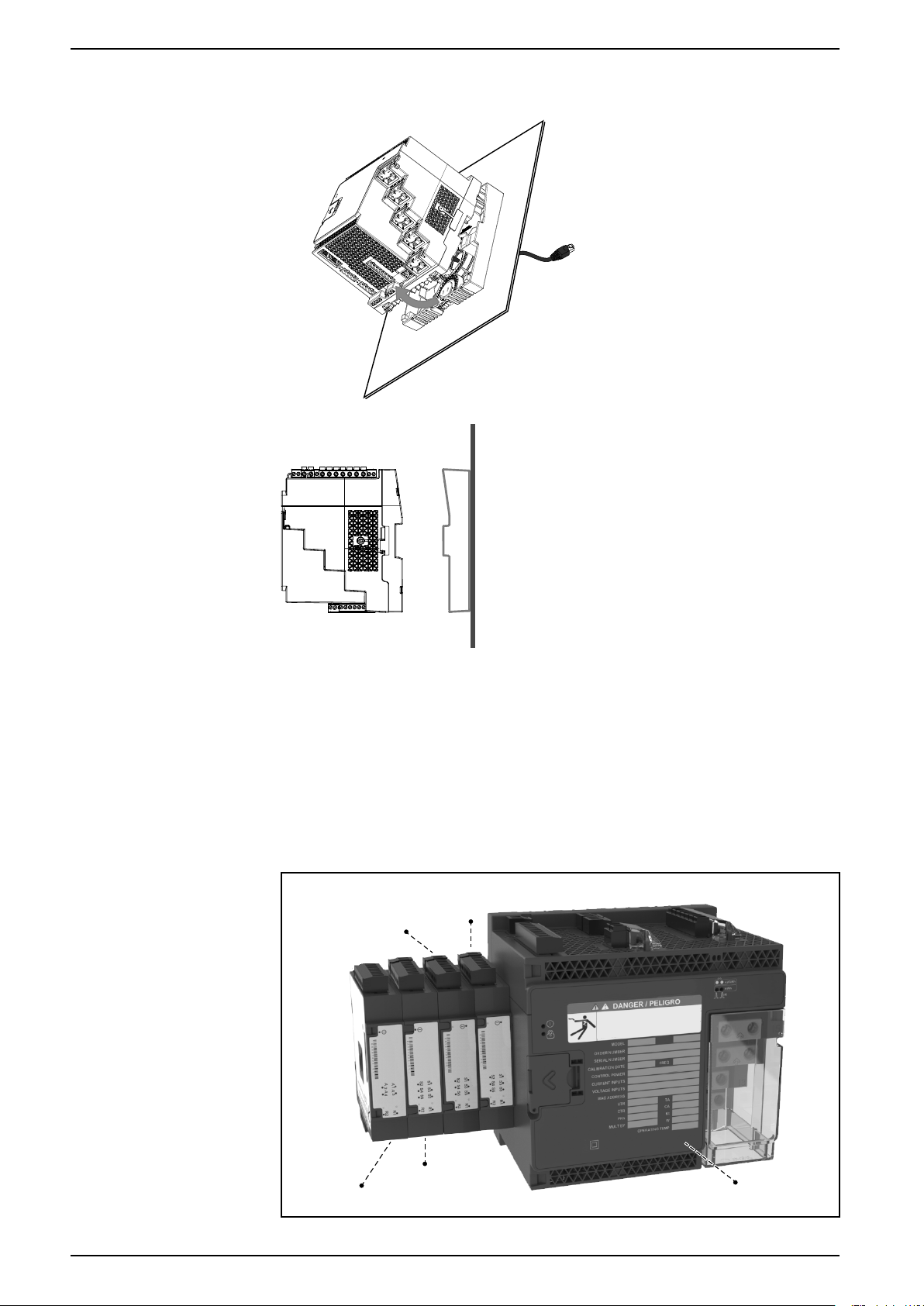
Module A
Module B
Module C
Module D
Meter
2. Holding the meter firmly, swing it outwards and pull slightly upwards to detach
it from the top retaining hooks.
Option modules
Option modules are ordered separately from your meter, and can be connected to
your meter without specialized equipment.
Option modules are identified based on how they physically connect to the meter’s
external I/O bus.
The first connected module, attached directly to the meter, is Module A. The
second module, attached to Module A, is Module B. The meter supports up to 4
external modules:
22 7EN05-0390-00

Installation and commissioning
The option modules are monitored and controlled by the meter’s ION modules.
External I/O modules are mapped to the corresponding ION modules:
Option module characteristic ION module characteristic
Physical position: Module A to Module D ION module label: Port A to Port D
Analog inputs A1 to A(n) Analog Input module A1 to A(n)
Analog outputs Q1 to Q(n) Analog Output module Q1 to Q(n)
Digital inputs S1 to S(n) Digital Input module S1 to S(n)
Digital/relay outputs R1 to R(n) Digital Output module R1 to R(n)
Maximum number of option modules
The maximum number of option modules supported by the device is four.
However, there are limitations.
Depending on the type and quantity of option modules attached to your meter, you
may need to reduce your meter’s maximum operating temperature or limit the
number of option modules. Refer to Maximum operating temperature with option
modules, page 214 for more information.
Commissioning
Factory default settings
NOTICE
EQUIPMENT DAMAGE
Failure to follow these instructions can result in equipment damage.
Do not exceed the maximum number of option modules.
Use these default values the first time you connect to your meter.
Parameter Default value
Password to log onto meter webpages or access display 0
Username to log onto meter webpages 9810
IP address
Subnet mask 255.255.0.0
Gateway 0.0.0.0
RS-485 COM1 Unit ID: 100
Language English
1
The IPv6 link local address can also be used. Refer to “Self-discovery over Ethernet”, page 28 for
details.
1
169.254.0.10
COM4 Unit ID: 103
Commissioning using ION Setup
Use ION Setup to commission the meter for integration into your energy
management system.
Connect to your meter using ION Setup then use the Setup Assistant to configure
the meter. Setup parameters are arranged in logical groupings and category
folders.
7EN05-0390-00 23

Before exiting the Setup Assistant, ION Setup performs a meter configuration test
and displays the results. You can review the results and make changes as
needed.
To turn off the meter configuration test:
1. Click Tools > Options.
2. Click the Assistant tab and clear the Configuration Checklist check box.
NOTE: ION Setup also performs a configuration test and displays results
when configuring certain features such as the Sag/Swell or Transient Logging
wizard in the Power Quality setup assistant.
Configure basic metering parameters
Use ION Setup’s Metering setup assistant to configure the meter’s basic metering
functionality.
1. Start ION Setup then open the Setup assistant for your meter.
2. Configure the parameters in Metering Setup > Basic.
Basic tab
Installation and commissioning
Parameter Values Description
Volts Mode 4W-WYE, DELTA,
3W-WYE, SINGLE,
DEMO
PT Prim 1 to 999,999 Potential transformer's primary winding
PT Sec 1 to 999,999 Potential transformer's secondary
CT Primary 1 to 999,999 Current transformer's primary winding
CT Secondary 1 to 999,999 Current transformer's secondary winding
Nominal Voltage 1 to 999,999 Nominal voltage (V) used for metering
Nominal Current 1 to 999,999 Nominal current (A) used for metering
Nominal Frequency 50, 60 Nominal frequency (Hz) used for
Power system type (note DEMO is
demonstration mode only, and does not
use the meter input terminals to display
values)
voltage rating
winding voltage rating
current rating
current rating
functions such as harmonic calculations
and sag/swell detection
functions such as harmonic calculations
and sag/swell detection
metering functions such as alarms
24 7EN05-0390-00

Installation and commissioning
3. Configure the parameters in Metering Setup > Advanced if appropriate.
Advanced tab
Parameter Values Description
Using the phasor viewer
PhaseOrder ABC, ACB Power system’s rotation order of voltage
phases
V4 PT Prim 1 to 999,999 V4 potential transformer's primary
winding voltage rating
V4 PT Sec 1 to 999,999 V4 potential transformer's secondary
winding voltage rating
I4 Prim 1 to 999,999 I4 current transformer's primary winding
current rating
I4 Sec 1 to 999,999 I4 current transformer's secondary
winding current rating
I5 Prim 1 to 999,999 I5 current transformer's primary winding
current rating
I5 Sec 1 to 999,999 I5 current transformer's secondary
winding current rating
Scale Rev Param ON, OFF Specifies whether revenue readings are
presented as primary or secondary side
values (ON = primary side, OFF =
secondary side)
Phasor diagrams can help verify or troubleshoot issues with voltage and current
input wiring.
Use ION Setup’s Phasor Viewer to display a real-time phasor diagram of the
voltage and current input signals.
1. Start ION Setup then open the Setup assistant for your meter.
2. Select Metering Setup > Phasor.
3. Select Phasor Viewer and click Show.
4. To change the polarity of the voltage or current inputs, click Show Setup to
display the Polarity Settings.
Select the box beside the inputs you want to invert polarity, then click Apply
to Meter.
Basic setup using the webpages or display
You can use the meter webpages or display to configure basic metering
parameters.
• Using the webpages: Navigate to Setup > Metering.
• Using the display: Navigate to Setup Menu > Meter Setup.
7EN05-0390-00 25

Communications
Communications overview
Communications is the transfer of data to and from the meter and is controlled by
a combination of hardware and software components in the meter.
For each connected communications port, the meter uses the applicable
communications protocol to establish communications with other devices or
software. The protocol manages the communications session and defines the set
of rules, commands and packet structure of the transmitted data. You can also
control which protocols are enabled or disabled on the meter.
NOTE: To maximize the performance of your power management system, it is
recommended that devices be connected directly to an Ethernet network.
Other means of controlling communications, such as who can access certain
types of meter data, are discussed in the security topics for the meter.
Your meter’s default protocol settings meet the needs of most systems with only
basic configuration. You can customize these settings to meet your specific needs.
These are advanced procedures that require an understanding of your meter’s
architecture, supported protocols, and the communications network and power
system that your meter is connected to.
Communications
Ethernet communications
Your Ethernet connection source should be installed in a location that helps
minimize the overall Ethernet cable routing length and complexity of your network.
The meter supports a single IP address for both physical Ethernet connections.
Your device’s second Ethernet port acts as an Ethernet switch to help simplify
network connections and reduce installation time and costs, by having shorter
Ethernet cable runs between devices without needing additional Ethernet routers
or repeaters. You cannot connect your meter to two different Ethernet networks.
The two Ethernet ports do not split the signal, so connecting both of the ports
should not impact your communications speed.
The meter uses dual-stack IPv4/IPv6 routing technology to manage network
communications and allow network hosts to communicate with the meter using
either IPv4 or IPv6.
Ethernet communications connections
Your meter’s dual port Ethernet connections enable you to use straight-line or
network loop (ring) topology.
If local network loop Ethernet topology is required, you must enable RSTP for your
meter’s Ethernet communications to function.
Use CAT5 (or higher) Ethernet cables with unshielded RJ45 modular connectors
to wire your meter’s Ethernet communications.
26 7EN05-0390-00

Communications
Ethernet loop topology
Protocols, ports and connections
A. Ethernet switch or hub
B. Ethernet connected
meters
C. LAN / WAN
The Ethernet protocols supported by your device allow simultaneous connections
through the IP service ports.
NOTE: Some protocol port numbers are read-only and not configurable.
Protocol Port (default) Number of
ION 7700
DNP 20000
DLMS 4059
Modbus TCP
3
Modbus RTU over Ethernet
Modbus TCP (dedicated)
3
3
502
7701
502 32
EtherGate (Com1) 7801 1
EtherGate (Com4) 7802 1
DHCP 67 (68) 1
FTP 21 (20) 2
Webserver (HTTP)
2
Secure webserver (HTTPS)
2
80 10
443 10
SNMP 161 N/A
SMTP server (email) outgoing only 25 1
connections
1
8
NTP 123 1
IEC 61850 102 5
1
These 8 simultaneous connections are shared by ION, Modbus TCP, Modbus RTU over Ethernet,
DNP and DLMS. You can have a maximum of 3 DNP connections. You can have a maximum of 1
DLMS connection.
2
These are used for the meter’s webpages.
3
These protocols must be enabled for Modbus gateway functionality.
By enabling or disabling TCP/IP protocols, you can control whether or not your
meter accepts new socket connection requests. Changing settings for one port
does not impact the other existing connections. Depending on the protocol, you
can also change the port number.
7EN05-0390-00 27

Related Topics
• Network protocol control
Self-discovery over Ethernet
Your meter supports DPWS (devices profile for web services) which allows for
self-discovery of the meter when it is connected to your local area network.
When you connect your meter to your network, your meter automatically appears
in your network in Windows Explorer under Other Devices. By default, the meter is
named <meter type>-<last six digits of MAC address>. For example, a meter with
a MAC address of 006078173393 appears on the network as
<meter type>-173393.
Communications
A Computer connected to the network with IPv6 enabled
B LAN / WAN (Local Area Network / Wide Area Network), common subnet, no routers
C Meters with self-discovery over Ethernet connected to the network
Considerations for using self-discovery over Ethernet
• For self-discovery, the meter must be connected directly to the network using
only a cable or switches, and not going through a router.
• You must use a computer running Windows 7 or later with IPv6 enabled in
order to use self-discovery over Ethernet.
• The computer and the meter must be on the same subnet.
• You do not need to configure your meter’s IP address for self-discovery over
Ethernet. An IPv6 address is automatically generated from your meter’s MAC
address and self-discovery takes place over IPv6.
Accessing the meter through self-discovery
You can use Windows Explorer to locate and access the meter on your Local Area
Network (LAN).
NOTE: Some networks restrict device self-discovery over a wireless
connection. If this is the case, make sure your computer is connected to the
network using an Ethernet cable.
1. Connect the meter’s Ethernet port to the LAN.
2. Start Windows Explorer.
3. Click Network.
The connected network devices display.
4. Locate your meter with the name <Device Name>-<Last 6 digits of MAC
address>.
5. Double-click the icon to open the meter webpages.
28 7EN05-0390-00

Communications
Ethernet configuration
In order to use Ethernet communications, you must configure your device’s IP
settings.
You need to enter network information for any Ethernet servers used by the device
(for example, a DNS or email server). Contact your network system administrator
for your IP address and other Ethernet network configuration values.
NOTE: For meters that do not have a display, you must connect your meter
directly to your computer to set a unique IP address for each device or
configure the meter to use a DHCP server to acquire IP addresses.
It is recommended that you test your communications with the meter after
changing any communications-related settings (for example, communicating with
the meter using the fully-qualified domain name if using DNS or with assigned
addresses after these are provided by the DHCP server). In addition, make sure
that any software or other devices communicating with the meter are using the
new settings.
Initial Ethernet configuration versus changing existing Ethernet settings
There are two scenarios when configuring your meter’s Ethernet communications
settings: initial configuration and changing the existing addresses when the meter
is in use.
• Initial configuration: Configure your device’s Ethernet settings manually using
the display or by connecting your meter directly to your computer and using a
web browser to access the device’s webpages. Alternately, you can connect
your meter to the network and configure it to use a DHCP server to acquire an
IP address.
NOTE: It is recommended during initial configuration that you use a
connection method other than the one your are trying to configure. For
example, if you are configuring DHCP IPv4 settings, connect to the meter
using the IPv6 LinkLocal address or a serial connection. This allows you
to configure the meter without being disconnected.
• Changing existing IP settings: After the meter’s Ethernet port is configured
and connected to the LAN, you can use ION Setup to configure meter
settings, in addition to using the display or meter webpages.
In either case, modify your meter’s Ethernet settings to those provided by your
network system administrator before connecting the device to your local area
network (LAN).
IP address format and ranges
When you set your meter’s IPv4 or IPv6 addresses, make sure you use the
correct format and valid ranges.
Protocol Format
IPv4 0.0.0.0 to 255.255.255.255
IPv6 :: to FFFF:FFFF:FFFF:FFFF:FFFF:FFFF:FFFF:
FFFF
The double colon indicates that gaps are filled
with zeroes to make the IPv6 address the
correct length (32 hexadecimal numbers)
All meters ship from the factory with the IPv6 global address and IPv6 gateway
undefined (set to “::”). To communicate with the meter using IPv6 outside the local
network, you must configure these settings manually or use DHCP to assign the
addresses to the meter. Within the local network, you can use the meter’s IPv6
Link Local address.
IP addresses and network port numbers
To specify a port for an outgoing IP address, append a colon (:) then the port
number to the end of the IP address. For IPv6 addresses, make sure the address
7EN05-0390-00 29

Communications
is enclosed in square brackets then append the port number. For example, to
specify the default port for ftp (port 21), the format of the address is as follows:
• IPv4: 169.254.0.10:21
• IPv6: [FE80::260:78FF:FE04:5943]:21
Configurable Ethernet settings
‘W’ indicates the setting can be configured (written) while ‘R’ indicates it is readonly.
NOTE: Some additional Ethernet settings are available in the Advanced
Ethernet menu in ION Setup and on the meter webpages.
Setting Display ION Setup Webpages
IPv4 address W W W
IPv4 Subnet mask W W W
IPv4 Default gateway W W W
IPv4 Assignment
Mode (DHCP/Stored)
IPv6 Assignment
Mode (DHCP/Stored)
Ethernet Device name R W W
Domain name R W W
IPv6 enabled W W W
IPv6 Link Local
Address
IPv6 global address R W W
IPv6 gateway R W W
Ethernet Rx timeout
Modbus TCP timeout
Modbus gateway
MAC address R R R
Ethernet primary DNS R W W
Ethernet secondary
DNS
W W W
W W W
R R R
—
—
—
R W W
W W
W W
W
—
Configuring IPv4 / IPv6 communications settings using ION Setup
You can configure your device’s IPv4 and IPv6 address settings, such as stored
addresses or address assignment mode, using ION Setup.
When configuring communications parameters, ensure you maintain at least one
communication path that allows full access to your device; otherwise you may
permanently lose the ability to change your device’s configuration and access
additional data.
NOTICE
LOSS OF ACCESS
Failure to follow these instructions can result in loss of access to the
device.
Ensure you maintain sufficient access to communicate with and configure your
device.
Contact your network system administrator for your IP addresses and other
Ethernet network configuration values.
30 7EN05-0390-00
 Loading...