

Page 1

Koellner
UROSKOP ACCESS
Installation Instructions
System
SP
System
0575612205756130
Print No.:
Replaces: SPL5-330.812.01.07.02
SPL5-330.812.01.08.02
© Siemens AG
The reproduction, transmission or use
of this document or its contents is not
permitted without express written
authority. Offenders will be liable for
damages. All rights, including rights
created by patent grant or registration
of a utility model or design, are
reserved.
English
Doc. Gen. Date: 01.06
2004
Page 2

2 Revision / Disclaimer
1Revision / Disclaimer
Document revision level
The document corresponds to the version/revision level effective at the time of system
delivery. Revisions to hardcopy documentation are not automatically distributed.
Please contact your local Siemens office to order current revision levels.
Disclaimer
The installation and service of equipment described herein is to be performed by qualified
personnel who are employed by Siemens or one of its affiliates or who are otherwise
authorized by Siemens or one of its affiliates to provide such services.
Assemblers and other persons who are not employed by or otherwise directly affiliated
with or authorized by Siemens or one of its affiliates are directed to contact one of the
local offices of Siemens or one of its affiliates before attempting installation or service procedures.
UROSKOP ACCESS SPL5-330.812.01.08.02 Siemens AG
01.06 CS PS SP
Page 2 of 90
Medical Solutions
Page 3

Table of Contents 3
1- 0Table of Contents
1 _______ Prerequisites / Notes _____________________________________________ 5
Prerequisites. . . . . . . . . . . . . . . . . . . . . . . . . . . . . . . . . . . . . . . . . . . . . . . . . . . . . . . . . . . 5
Required aids and tools . . . . . . . . . . . . . . . . . . . . . . . . . . . . . . . . . . . . . . . . . . . . . . . 5
Required documents. . . . . . . . . . . . . . . . . . . . . . . . . . . . . . . . . . . . . . . . . . . . . . . . . . 5
Room preparations . . . . . . . . . . . . . . . . . . . . . . . . . . . . . . . . . . . . . . . . . . . . . . . . . . . 6
Notes . . . . . . . . . . . . . . . . . . . . . . . . . . . . . . . . . . . . . . . . . . . . . . . . . . . . . . . . . . . . . . . . 7
Safety information . . . . . . . . . . . . . . . . . . . . . . . . . . . . . . . . . . . . . . . . . . . . . . . . . . . . 7
Product-specific notes. . . . . . . . . . . . . . . . . . . . . . . . . . . . . . . . . . . . . . . . . . . . . . . . . 7
Completing the installation certificate . . . . . . . . . . . . . . . . . . . . . . . . . . . . . . . . . . . . . 7
Tolerance data . . . . . . . . . . . . . . . . . . . . . . . . . . . . . . . . . . . . . . . . . . . . . . . . . . . . . . 8
Tightening torques . . . . . . . . . . . . . . . . . . . . . . . . . . . . . . . . . . . . . . . . . . . . . . . . . . . 8
Colors used. . . . . . . . . . . . . . . . . . . . . . . . . . . . . . . . . . . . . . . . . . . . . . . . . . . . . . . . . 8
Abbreviations . . . . . . . . . . . . . . . . . . . . . . . . . . . . . . . . . . . . . . . . . . . . . . . . . . . . . . . 8
2 _______ Lifting base_____________________________________________________ 9
Installation preparations . . . . . . . . . . . . . . . . . . . . . . . . . . . . . . . . . . . . . . . . . . . . . . . . . . 9
Accessories for the lifting base . . . . . . . . . . . . . . . . . . . . . . . . . . . . . . . . . . . . . . . . . . 9
Installing the transport rollers on the lifting base . . . . . . . . . . . . . . . . . . . . . . . . . . . . . . 10
Positioning and installing the lifting base . . . . . . . . . . . . . . . . . . . . . . . . . . . . . . . . . . . . 11
Checking the safety switch (back of the lifting base) . . . . . . . . . . . . . . . . . . . . . . . . . . . 15
3 _______ Unit carrier ____________________________________________________ 17
Installation on the lifting base . . . . . . . . . . . . . . . . . . . . . . . . . . . . . . . . . . . . . . . . . . . . . 17
Installation of power supply module (M1). . . . . . . . . . . . . . . . . . . . . . . . . . . . . . . . . . . . 19
Wiring . . . . . . . . . . . . . . . . . . . . . . . . . . . . . . . . . . . . . . . . . . . . . . . . . . . . . . . . . . . . . . . 20
Unit transformer . . . . . . . . . . . . . . . . . . . . . . . . . . . . . . . . . . . . . . . . . . . . . . . . . . . . 20
Wiring of M1/M2 . . . . . . . . . . . . . . . . . . . . . . . . . . . . . . . . . . . . . . . . . . . . . . . . . . . . 20
Installation of image intensifier I.I 33/I.I. 40 . . . . . . . . . . . . . . . . . . . . . . . . . . . . . . . . . . 25
Reading the temperature indicators on the I.I. . . . . . . . . . . . . . . . . . . . . . . . . . . . . . 25
4 _______ Multileaf collimator _____________________________________________ 26
Installing the collimator. . . . . . . . . . . . . . . . . . . . . . . . . . . . . . . . . . . . . . . . . . . . . . . . . . 26
5 _______ TFT monitor support arm ________________________________________ 28
Installing the TFT support arm . . . . . . . . . . . . . . . . . . . . . . . . . . . . . . . . . . . . . . . . . . . . 28
6 _______ Cabling _______________________________________________________ 35
General information . . . . . . . . . . . . . . . . . . . . . . . . . . . . . . . . . . . . . . . . . . . . . . . . . . . . 35
Labeling of the cable harnesses . . . . . . . . . . . . . . . . . . . . . . . . . . . . . . . . . . . . . . . . 35
List of fixed points . . . . . . . . . . . . . . . . . . . . . . . . . . . . . . . . . . . . . . . . . . . . . . . . . . . 36
POLYDOROS SX65/80 cabling . . . . . . . . . . . . . . . . . . . . . . . . . . . . . . . . . . . . . . . . . . . 39
Overview: cable connection and cable layout in the generator cabinet . . . . . . . . . . 39
Generator power connection. . . . . . . . . . . . . . . . . . . . . . . . . . . . . . . . . . . . . . . . . . . 40
Connecting the rotating anode cables . . . . . . . . . . . . . . . . . . . . . . . . . . . . . . . . . . . 41
Siemens AG SPL5-330.812.01.08.02 UROSKOP ACCESS
Medical Solutions
01.06 CS PS SP
Page 3 of 90
Page 4

4 Table of Contents
Connection of the Iontomat measuring chamber. . . . . . . . . . . . . . . . . . . . . . . . . . . . 41
Connection of the HV trigger/gray filter . . . . . . . . . . . . . . . . . . . . . . . . . . . . . . . . . . . 42
XCU cable connection . . . . . . . . . . . . . . . . . . . . . . . . . . . . . . . . . . . . . . . . . . . . . . . . 42
Inserting the high-voltage transformer into the generator cabinet. . . . . . . . . . . . . . . 43
Connecting the high-voltage cables . . . . . . . . . . . . . . . . . . . . . . . . . . . . . . . . . . . . . 44
Connecting the primary cables . . . . . . . . . . . . . . . . . . . . . . . . . . . . . . . . . . . . . . . . . 45
Monitoring devices and displays for radiation protection. . . . . . . . . . . . . . . . . . . . . . 46
Connecting the ground wires. . . . . . . . . . . . . . . . . . . . . . . . . . . . . . . . . . . . . . . . . . . 47
Monitors in the control room . . . . . . . . . . . . . . . . . . . . . . . . . . . . . . . . . . . . . . . . . . . . . . 48
Systems without a urodynamics interface . . . . . . . . . . . . . . . . . . . . . . . . . . . . . . . . . 48
Systems with a urodynamics interface . . . . . . . . . . . . . . . . . . . . . . . . . . . . . . . . . . . 48
Explanations of the various monitor types. . . . . . . . . . . . . . . . . . . . . . . . . . . . . . . . . 49
FLUOROSPOT Compact imaging system container . . . . . . . . . . . . . . . . . . . . . . . . . . . 51
Mouse . . . . . . . . . . . . . . . . . . . . . . . . . . . . . . . . . . . . . . . . . . . . . . . . . . . . . . . . . . . . 52
Network . . . . . . . . . . . . . . . . . . . . . . . . . . . . . . . . . . . . . . . . . . . . . . . . . . . . . . . . . . . 52
Keyboard . . . . . . . . . . . . . . . . . . . . . . . . . . . . . . . . . . . . . . . . . . . . . . . . . . . . . . . . . . 52
Laser printer connection . . . . . . . . . . . . . . . . . . . . . . . . . . . . . . . . . . . . . . . . . . . . . . 52
Back of the imaging system PC (cabling only as an example) . . . . . . . . . . . . . . . . . 53
Cabling of the imaging system container. . . . . . . . . . . . . . . . . . . . . . . . . . . . . . . . . . 54
Board D1 (BUC) - connector overview . . . . . . . . . . . . . . . . . . . . . . . . . . . . . . . . . . . 58
Cable harness installation . . . . . . . . . . . . . . . . . . . . . . . . . . . . . . . . . . . . . . . . . . . . . . . . 59
W100 system (tube assembly) - POLYDOROS SX . . . . . . . . . . . . . . . . . . . . . . . . . 59
W150 system (I.I.) - POLYDOROS SX . . . . . . . . . . . . . . . . . . . . . . . . . . . . . . . . . . . 59
Additional cables . . . . . . . . . . . . . . . . . . . . . . . . . . . . . . . . . . . . . . . . . . . . . . . . . . . . 59
W360 unit (M1) - control console (M11) . . . . . . . . . . . . . . . . . . . . . . . . . . . . . . . . . . 60
W400 system (M1) - POLYDOROS SX. . . . . . . . . . . . . . . . . . . . . . . . . . . . . . . . . . . 60
W600 POLYDOROS SX - imaging system container . . . . . . . . . . . . . . . . . . . . . . . . 60
W650 imaging system container - TFT support arm . . . . . . . . . . . . . . . . . . . . . . . . . 61
Data printer connection (label printer, optional). . . . . . . . . . . . . . . . . . . . . . . . . . . . . 61
Remote control panel cabling (optional) . . . . . . . . . . . . . . . . . . . . . . . . . . . . . . . . . . . . . 62
Installing the endo shelf (optional) . . . . . . . . . . . . . . . . . . . . . . . . . . . . . . . . . . . . . . . . . 64
Right-hand version of the endoscopy shelf . . . . . . . . . . . . . . . . . . . . . . . . . . . . . . . . 65
Left-hand version of the endoscopy shelf . . . . . . . . . . . . . . . . . . . . . . . . . . . . . . . . . 65
Installing the endo shelf on the unit carrier . . . . . . . . . . . . . . . . . . . . . . . . . . . . . . . . 66
Endoscopy interface connection (optional) . . . . . . . . . . . . . . . . . . . . . . . . . . . . . . . . . . . 68
Connecting the foot switch . . . . . . . . . . . . . . . . . . . . . . . . . . . . . . . . . . . . . . . . . . . . . . . 69
ASPIA imaging system container . . . . . . . . . . . . . . . . . . . . . . . . . . . . . . . . . . . . . . . . . . 70
Mouse . . . . . . . . . . . . . . . . . . . . . . . . . . . . . . . . . . . . . . . . . . . . . . . . . . . . . . . . . . . . 71
Network . . . . . . . . . . . . . . . . . . . . . . . . . . . . . . . . . . . . . . . . . . . . . . . . . . . . . . . . . . . 71
Keyboard . . . . . . . . . . . . . . . . . . . . . . . . . . . . . . . . . . . . . . . . . . . . . . . . . . . . . . . . . . 71
Laser printer connection . . . . . . . . . . . . . . . . . . . . . . . . . . . . . . . . . . . . . . . . . . . . . . 72
Back of the imaging system PC. . . . . . . . . . . . . . . . . . . . . . . . . . . . . . . . . . . . . . . . . 72
Cabling of the imaging system container. . . . . . . . . . . . . . . . . . . . . . . . . . . . . . . . . . 73
7 _______ Final work steps (covers) ________________________________________ 78
Covers for the imaging system container . . . . . . . . . . . . . . . . . . . . . . . . . . . . . . . . . . . . 78
Lifting base covers . . . . . . . . . . . . . . . . . . . . . . . . . . . . . . . . . . . . . . . . . . . . . . . . . . . . . 85
8 _______ Changes to Previous Version _____________________________________ 88
UROSKOP ACCESS SPL5-330.812.01.08.02 Siemens AG
01.06 CS PS SP
Page 4 of 90
Medical Solutions
Page 5

Prerequisites / Notes 5
1Prerequisites / Notes
2-
Prerequisites 0
Required aids and tools 0
NOTE
All listed tools and measuring and auxiliary equipment except for
the customary installation tools are listed in the Service Tools Catalogue (as part of the Spare Part Catalogue).
Drilling machine with a tapping drill n.a.
Torque wrench 20-100 Nm 44 30 906 RH090
Torque wrench 40-200 Nm 80 86 142 RE999
Socket head insert, 14 mm 52 66 564
Loctite 221 n.a.
Silicon oil, AK350 17 87 035
Masonry drill (diameter d = 18 mm) n.a.
Transport rollers 11 53 654 G5338
Level (measuring accuracy: 1.0 mm/m) n.a.
Required documents 0
Installation and Start-up; Installation of options SPL5-330.814.02.xx
Installation and Start-up; Urodynamic Inter-
SPL5-330.814.01.xx
face/Scan Converter
Installation Certificate; Service Provider Documen-
SPL5-330.813.01.xx
tation
Installation Instructions for the UROSKOP Access
TFT Support Arm System (Ondal)
1519892/01-2005 (print number
from the manufacturer Ondal)
Project plan n.a.
Wiring Diagram SPL5-330.844.91.01.02 (57 56
130-EFS-01A)
Planning Guide; System; UROSKOP Access (e) SPL5-330.891.01.xx
UROSKOP ACCESS; Help File FLC SPL5-330.880.01.xx
X-Ray Diagnostic System; Installation Instruction;
RX0-000.031.01.xx
High voltage cable RH 098-5DF6 071
Siemens AG SPL5-330.812.01.08.02 UROSKOP ACCESS
Medical Solutions
01.06 CS PS SP
Page 5 of 90
Page 6

6 Prerequisites / Notes
Room preparations 0
• The floor covering must be removed in the area of the base plate and the transformer
trough.
• The lifting base and the transformer trough must be mounted directly on the concrete
floor.
- PVC or tiling must be removed first.
UROSKOP ACCESS SPL5-330.812.01.08.02 Siemens AG
01.06 CS PS SP
Page 6 of 90
Medical Solutions
Page 7
Prerequisites / Notes 7
Notes 0
• This document was originally written in German.
Safety information 0
Mechanical safety information
CAUTION
Risk of injury from mechanical parts!
If not observed, minor to more severe injury, especially to the
hands, can occur. After the covers are opened, parts such as flat
plugs, threaded bolts, cut-off cable ties and component edges are
exposed, and if care is not taken, they can cause crushing,
scrapes and cuts to the skin, particularly to the hands.
¹ Perform the required work with special care and atten-
tion to detail.
¹ If necessary, wear work gloves.
Product-specific notes 0
CAUTION
Risk of the unit carrier tipping!
Pushing on the longitudinal sides of the unit carrier when using
the transport frame and transport rollers to transport the unit carrier can result in tipping.
¹ Push the unit carrier on the front sides and not on the
longitudinal sides.
NOTE
Handle the TFT monitors with care. The monitors at the Uroskop
Access do not have touch screen functionality so that pressing on
the display surface could result in irreversible damage.
• Checking the cabling and power connection
- For safety reasons the power connection may be made only by the SIEMENS service engineer/electrician.
- The complete cabling must also be inspected by the SIEMENS service engineer before the system is switched on.
Completing the installation certificate 0
• Document “Installation Certificate; Service Provider Documentation“
(SPL5-330.813.01.xx) is to be filled out by the responsible service provider at the time
of installation and wiring. The installation result must be confirmed by signature of the
Siemens AG SPL5-330.812.01.08.02 UROSKOP ACCESS
Medical Solutions
01.06 CS PS SP
Page 7 of 90
Page 8
8 Prerequisites / Notes
responsible service provider and the project manager. Both the responsible service
provider and the person responsible for the project should receive a copy. The installation certificate is to be provided to the office specified in the document.
Tolerance data 0
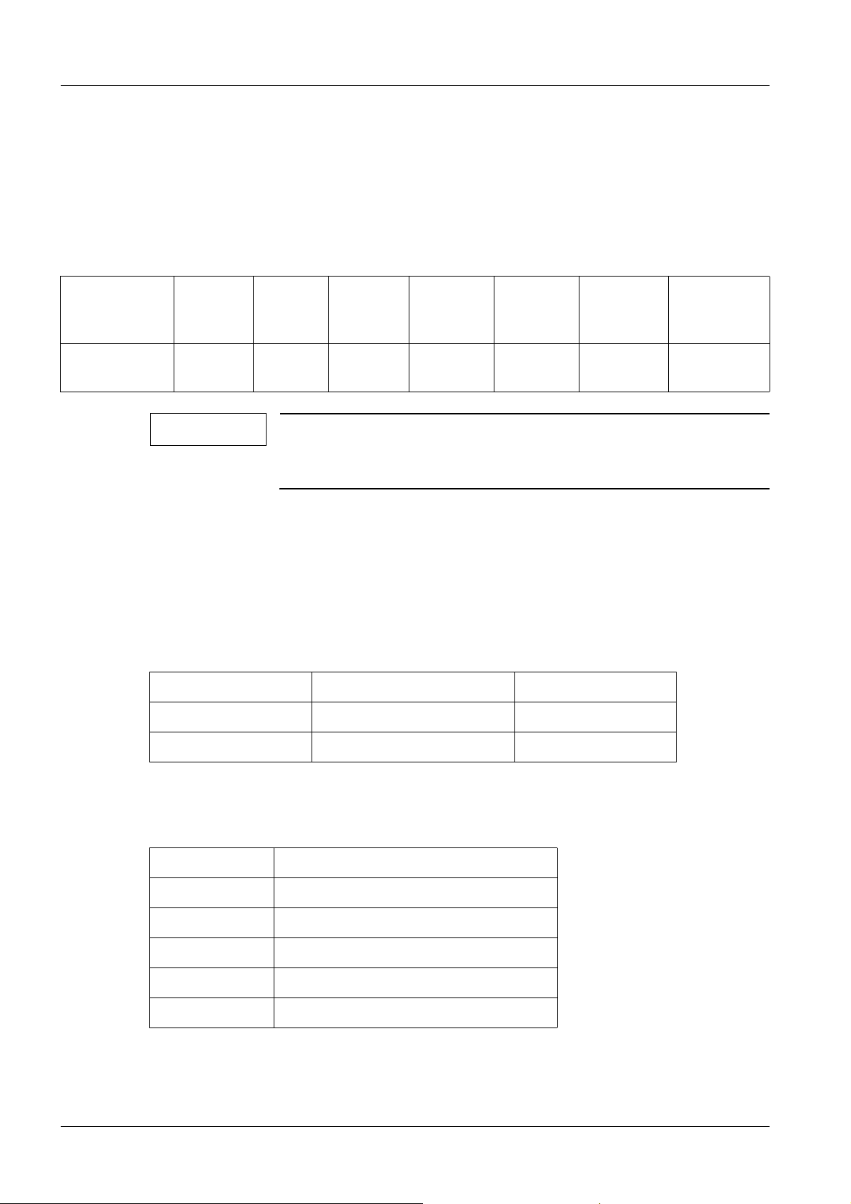
General tolerances for length dimensions according to ISO 2768
Limits of nominal size range
Admissible tolerance
over 3
mm to 6
mm
± 0.5 mm ± 1 mm ± 1.5 mm ± 2.5 mm ± 4 mm ± 6 mm ± 8 mm
NOTE
over 6
mm to
30 mm
These tolerances apply to all dimensions indicated in these instructions, unless other tolerances are specifically indicated after
the value.
over 30
mm to
120 mm
over 120
mm to 400
mm
over 400
mm to
1,000 mm
over 1,000
mm to
2,000 mm
over 2,000
mm to 4,000
mm
Tightening torques 0
• In the case of the tightening torque, a tolerance of ±10% is permissible.
Colors used 0
White Basic unit Part no. 34 42 472
Light Basic Unit Base Part no. 55 06 865
Medical Blue Emphasized areas Part no. 55 06 857
Abbreviations 0
IS Imaging system
II Image intensifier
FLC FLUOROSPOT Compact
TV Television
ISK Allen screw
LAN Local Area Network
UROSKOP ACCESS SPL5-330.812.01.08.02 Siemens AG
01.06 CS PS SP
Page 8 of 90
Medical Solutions
Page 9

Lifting base 9
2Lifting base
3-
Installation preparations 0
Accessories for the lifting base 0
• The lifting base comes with the following installation accessories:
- 6 anchors HSL-3 M12/50
- 6 anchors HSL-3 M12/100
- 6 plate washers
- Caps for the floor plate
-Shims
- Drilling template
Siemens AG SPL5-330.812.01.08.02 UROSKOP ACCESS
Medical Solutions
01.06 CS PS SP
Page 9 of 90
Page 10
10 Lifting base
Installing the transport rollers on the lifting base 0
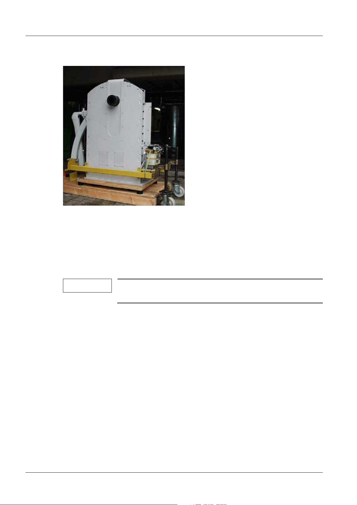
Fig. 1: Transport frame
• Fasten the 4 transport rollers to the transport frame via 2 Allen screws M12x25 and
washers per transport roller (Fig.1/p.10).
• Unscrew the lifting base from the pallet.
• Move the transport rollers down to just above the floor.
• Bring the lifting base into the examination room.
NOTE
The 4 Allen screws M 12 x 40 mm (3/Fig. 3 / p. 12) are required for
leveling the lifting base.
UROSKOP ACCESS SPL5-330.812.01.08.02 Siemens AG
01.06 CS PS SP
Page 10 of 90
Medical Solutions
Page 11
Lifting base 11
Positioning and installing the lifting base 0
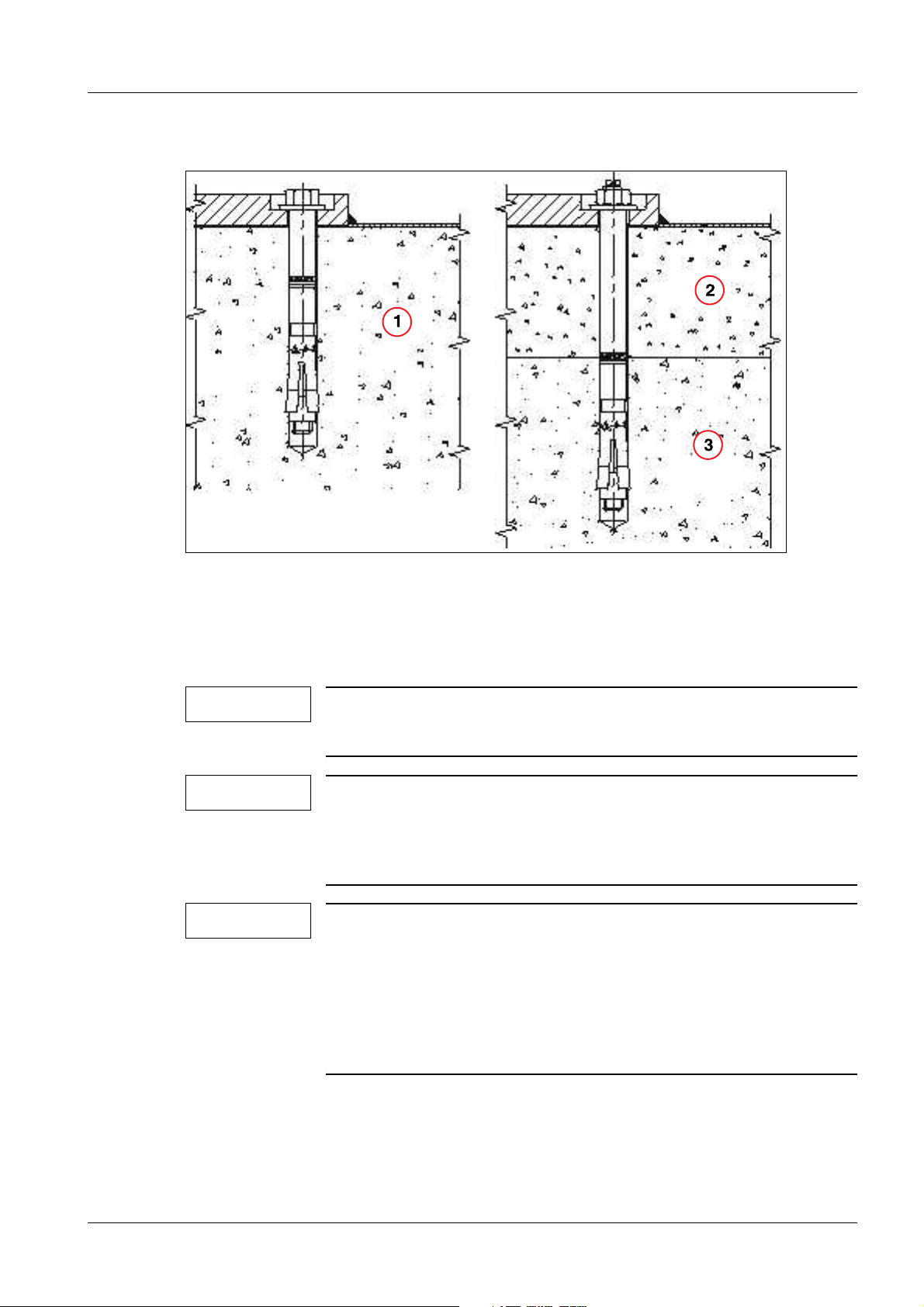
Fig. 2: Lifting base installation
Pos. 1 Concrete
Pos. 2 Screed
Pos. 3 Concrete
NOTE
Installation directly on concrete: (1/Fig.2/p.11)
Use anchors HSL-3 M12/50
NOTE
Installation in the case of a concrete filling when a floor topping
and insulating layer were not used: (2/Fig.2/p.11),
(3/Fig.2/p.11)
Use anchors HSL-3 M12/100
NOTE
The relevant type of safety anchors must be installed according to
the floor condition (also refer to the project plan).
If installing on an installation frame, M12 screws with strength
class 8.8 must be provided by the customer. When installing with
a drilled-through floor, M12 threaded rods with strength class 8.8
must be provided by the customer. Use the supplied washers with
screws or threaded rods. Secure screws or nuts with Loctite 221.
Example of a base plate with a lefthanded design
Siemens AG SPL5-330.812.01.08.02 UROSKOP ACCESS
Medical Solutions
01.06 CS PS SP
Page 11 of 90
Page 12
12 Lifting base
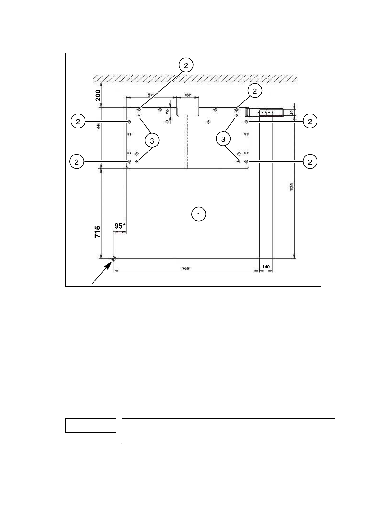
Fig. 3: Left-hand version of the base plate
• Mark the orientation point on the floor according to the project plan (see arrow,
(Fig.3/p.12)).
• Position the drilling template (1/Fig.3/p.12) according to the orientation point and
mark the positions of the 6 holes (2/Fig.3/p.12).
- Use alternative holes if necessary.
• Drill the holes at the marked positions.
• Vacuum the drilling dust out of the holes.
• Position the lifting base above the drilled holes and move it down.
• Insert the anchors in the drilled holes.
• Unscrew the transport rollers and transport holders from the lifting base.
NOTE
The lifting base may only be installed on a concrete floor. Any
flooring, e.g., PVC or tiling, must be removed.
UROSKOP ACCESS SPL5-330.812.01.08.02 Siemens AG
01.06 CS PS SP
Page 12 of 90
Medical Solutions
Page 13
Lifting base 13
NOTE
The transformer trough may only be installed on the concrete
floor. Any flooring, e.g. PVC or tiling, must be removed.
Fig. 4: Base plate
Pos. 1 Safety anchors
Pos. 2 Level
Pos. 3 Shims
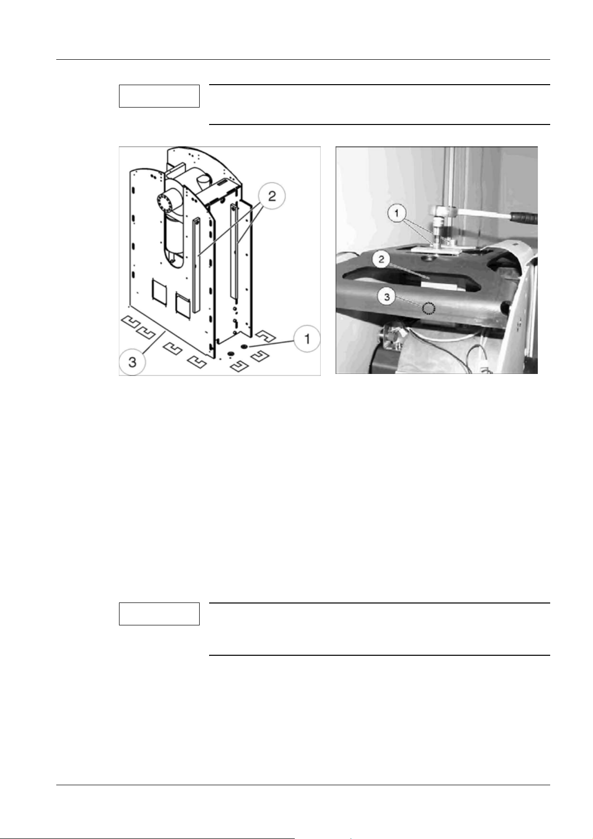
Fig. 5: Lifting base transport safety device
Pos. 1 Allen screws
Pos. 2 Allen screws
Pos. 3 Allen screws
• Screw in the leveling screws (M12 x 40) (3/Fig.3/p.12) and align the lifting base with
the aid of a level (2/Fig.4/p.13).
• Place the supplied shims as required underneath the outer edges of the base plate
(3/Fig.4/p.13).
• Place the shims along the opening in the middle of the base plate as needed.
• Loosen the leveling screws (3/Fig.3/p.12).
• Tighten the anchors or screws to check the leveling. Use a level to check the levelling
(2/Fig.4/p.13), if necessary add or remove shims until the base plate is longitudinally
and horizontally in the 0° position.
NOTE
T • Only when leveling is correct in a tightened state can the safety anchors be tightened
with a torque of 80 Nm (1/Fig.4/p.13).
The base plate must not tilt to the front in the direction of the orientation point under any circumstances. The lifting base may,
however, tilt slightly to the rear (max. 0.5°).
• To remove the transport safety device from the lifting base, unscrew the Allen screws
and then remove the transport safety device (1,2,3/Fig. 5 / p. 13).
Siemens AG SPL5-330.812.01.08.02 UROSKOP ACCESS
Medical Solutions
01.06 CS PS SP
Page 13 of 90
Page 14
14 Lifting base
NOTE
The transport safety device can be relieved by lowering the lifting
base with a ratchet (counterclockwise) (1/Fig.6/p.14).
NOTE
Screw (3/Fig.5/p.13) is located on the bottom of the transport
safety device.
• Screw the M12 x 30 screw (3/Fig.5/p.13) back into threaded hole of the gear box.
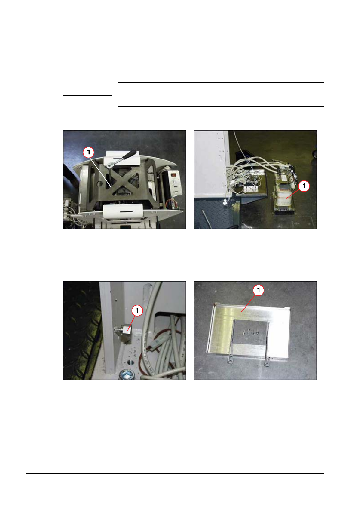
Fig. 6: Relieving the transport safety device
Pos. 1 Ratchet
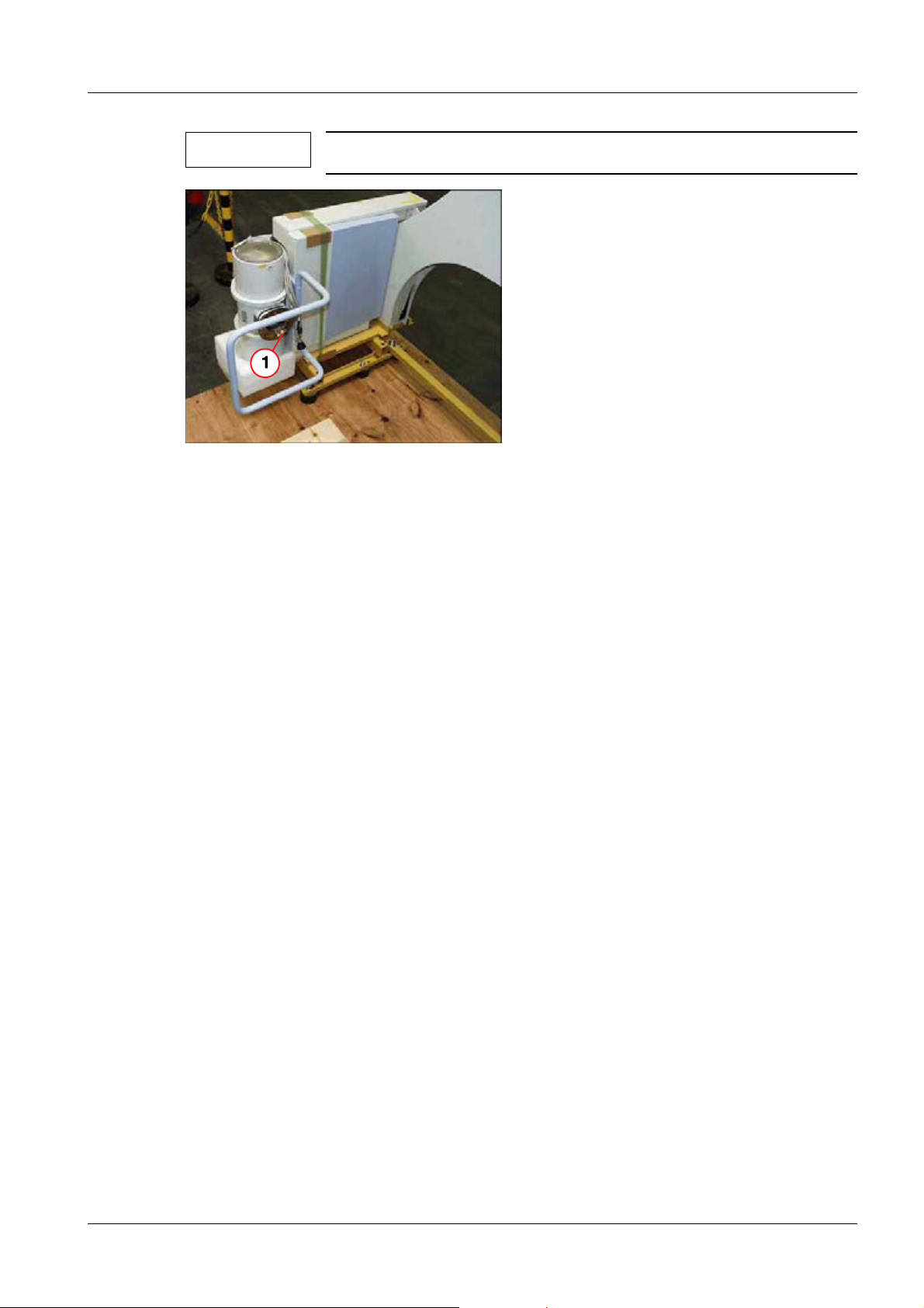
Fig. 7: Removing the system transformer
Pos. 1 System transformer
• Remove the system transformer from the transport frame and place it on the floor
(1/Fig.7/p.14).
Fig. 8: Unit base
Pos. 1 Bolt
Fig. 9: Transformer trough
Pos. 1 Transformer trough including the transformer
holder
• Screw the supplied bolts (1/Fig.8/p.14) into the unit base.
• Then bolt the transformer trough (1/Fig.9/p.14) including the transformer holder to
the unit base.
UROSKOP ACCESS SPL5-330.812.01.08.02 Siemens AG
01.06 CS PS SP
Page 14 of 90
Medical Solutions
Page 15
Lifting base 15
Checking the safety switch (back of the lifting base) 0
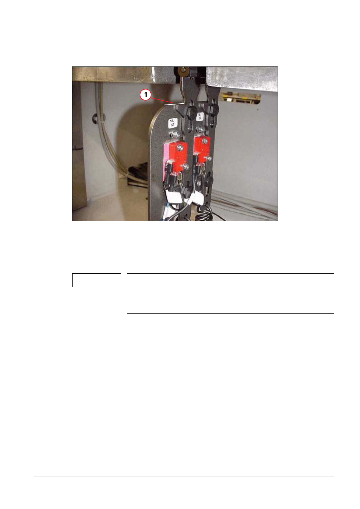
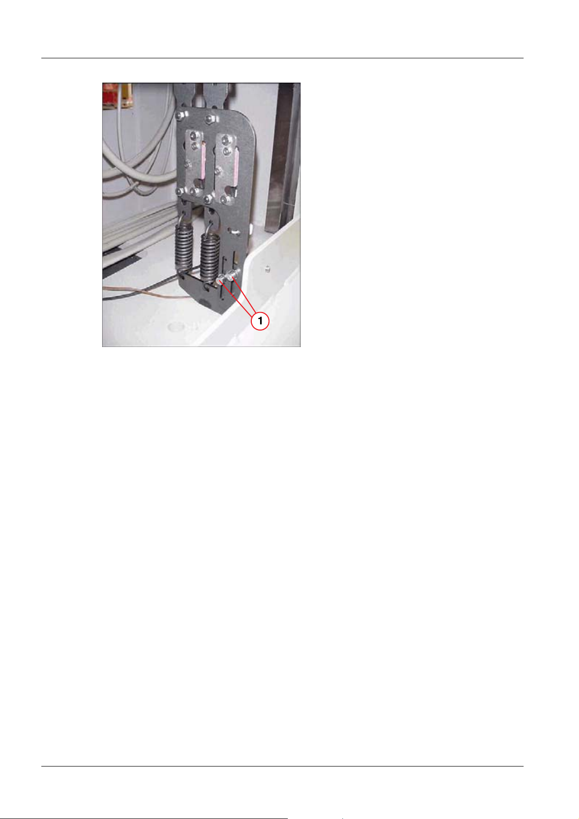
Fig. 10: Safety switch on the back of the lifting base
Pos. 1 Edge
• Align the marked edge of the moving part with the upper edge of the stationary part
(1/Fig. 10 / p. 15).
NOTE
When installing the lifting base, check the setting shown in
(1/Fig. 10 / p. 15) and adjust it if necessary by loosinging the two
Allen screws (1/Fig. 11 / p. 16). Subsequently retighten these
screws.
Siemens AG SPL5-330.812.01.08.02 UROSKOP ACCESS
Medical Solutions
01.06 CS PS SP
Page 15 of 90
Page 16
16 Lifting base
Fig. 11: Lifting base installation
Pos. 1 Allen screws
UROSKOP ACCESS SPL5-330.812.01.08.02 Siemens AG
01.06 CS PS SP
Page 16 of 90
Medical Solutions
Page 17
Unit carrier 17
3Unit carrier
4-
Installation on the lifting base 0
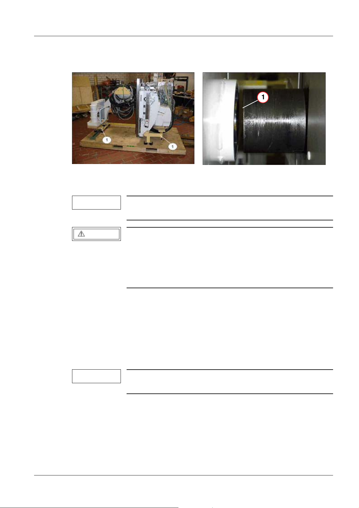
Fig. 12: Screwing on the transport frame
Pos. 1 Transport frame
NOTE
If necessary because of the width of the doors (< 1.15 m), the unit
Fig. 13: Unit carrier/lifting base
Pos. 1 Lifting base flange
carrier can be tilted to the left or right in the transport frame.
CAUTION
Risk of the unit carrier tipping!
Pushing on the longitudinal sides of the unit carrier when using
the transport frame and transport rollers to transport the unit carrier can result in tipping.
¹ Push the unit carrier on the front sides and not on the
longitudinal sides.
• Fasten the 4 transport rollers to the transport frame via 2 Allen screws M12 x 25 and
washers per transport roller (1/Fig. 12 / p. 17).
• Unscrew the transport frame from the pallet.
• Raise the unit carrier approx. 3 cm with the aid of the transport rollers and move it care-
fully off the pallet.
• Move the unit carrier to the lifting base and raise it to the level of the lifting base flange
with the aid of the transport rollers (1/Fig. 13 / p. 17).
NOTE
The collimator is delivered separately and is not on the unit carrier
pallet.
Siemens AG SPL5-330.812.01.08.02 UROSKOP ACCESS
Medical Solutions
01.06 CS PS SP
Page 17 of 90
Page 18
18 Unit carrier
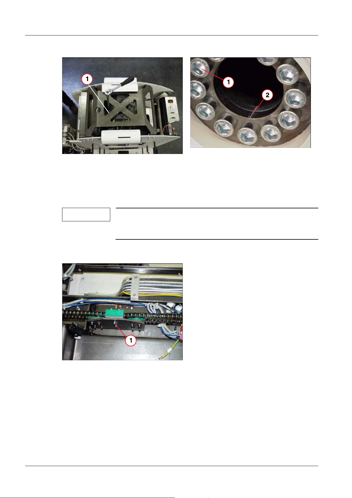
Fig. 14: Relieving the transport safety device
Pos. 1 Ratchet
Fig. 15: Unit carrier installation
Pos. 1 Screws M16 x 40
• Align the unit carrier to the flange of the lifting base by means of the marks made in the
factory (they must for a line) (2/Fig. 15 / p. 18) and carefully push the unit carrier onto
the flange of the lifting base.
NOTE
T • Secure the unit carrier with 12 screws M16 x 40 and Loctite 221 and tighten them
crosswise with a torque of 200 Nm (1/Fig. 15 / p. 18).
The distance between the flange and the lifting base can be
changed as needed via a ratchet (precision adjustment,
(Fig. 14 / p. 18)).
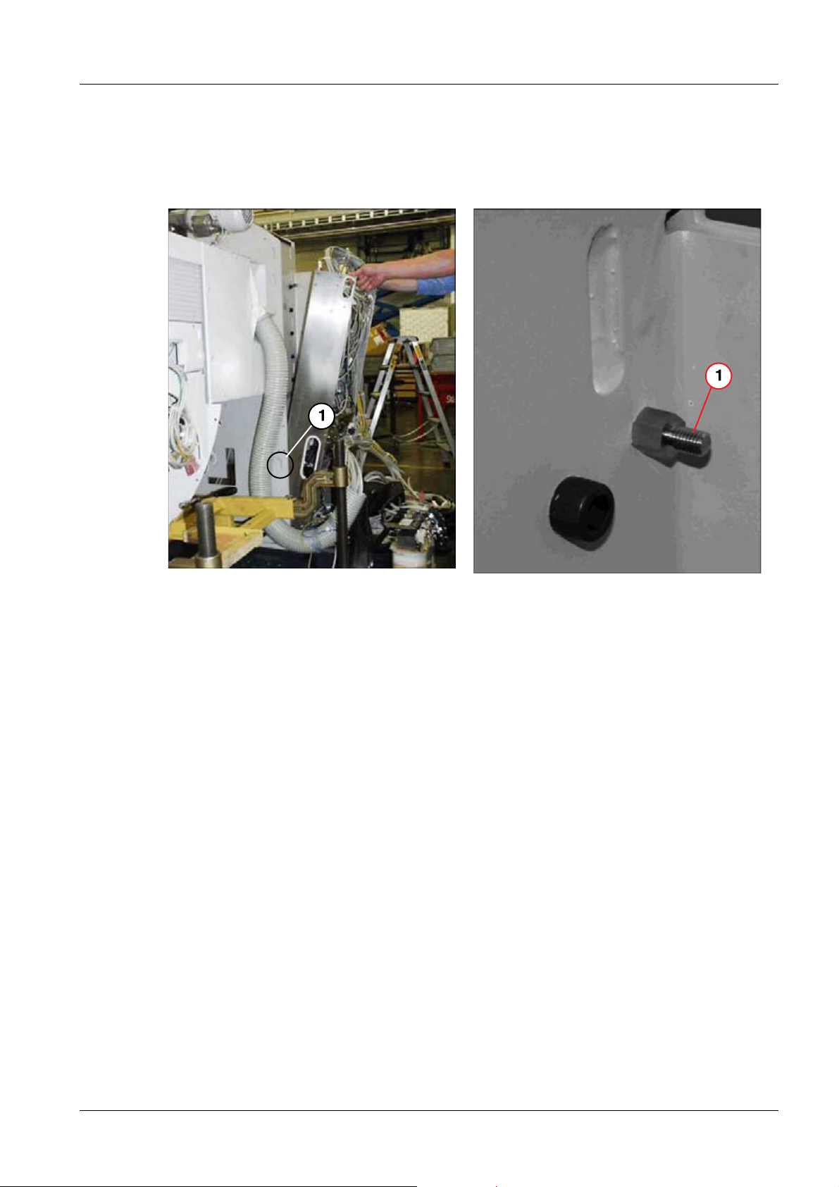
Fig. 16: Removing the transport safety device
Pos. 1 Red screw
• Remove the transport safety device below the chain guide for the transverse table drive
(red screw) (1/Fig. 16 / p. 18).
UROSKOP ACCESS SPL5-330.812.01.08.02 Siemens AG
01.06 CS PS SP
Page 18 of 90
Medical Solutions
Page 19
Unit carrier 19
Installation of power supply module (M1) 0
The layout (connector overview) of M1.D1 (BUC) is shown in this document
(Fig. 64 / p. 58).
Fig. 17: Power supply module
Pos. 1 Guide bolts on the inside of the lifting base
Fig. 18: Top lifting base bolt
Pos. 1 Securing the top bolt
• Remove the transport safety device (have 2 people lift the power supply module) and
insert it in the guide bolts on the lifting base (1/Fig. 17 / p. 19).
• Use 2 nuts to secure the power supply module at the upper bolt of the lifting base.
• Remove the corrugated hose from the transport frame.
• Completely remove the transport frame.
Siemens AG SPL5-330.812.01.08.02 UROSKOP ACCESS
Medical Solutions
01.06 CS PS SP
Page 19 of 90
Page 20

20 Unit carrier
Wiring 0
Unit transformer 0
• Connect cable M2 to the transformer.
• Connect the blue lead (N) and the ground wire to module M1.
Wiring of M1/M2 0
• Connect the following cables to M1.X20:
- 7 (brown),
- 8 (black),
-9 (blue),
- 10 (green-yellow).
• Plug in M1.X20.
• Screw in the strain relief device and tighten it securely.
• Plug in connector M1.X9 (fluoro acquisition) and attach the screws and safety device
again.
• Plug in connectors M1.D1.X111 and M1.D1.X512.
• Plug in connectors M1.X7 and M1.D1.X300.
• Connect the following connectors to M2:
-M2.D21.X2,
- M2.X4 - X7.
• Screw on M2.PE.
• Plug in connector M1.D1.X110 and attach the cable clamp.
UROSKOP ACCESS SPL5-330.812.01.08.02 Siemens AG
01.06 CS PS SP
Page 20 of 90
Medical Solutions
Page 21
Unit carrier 21
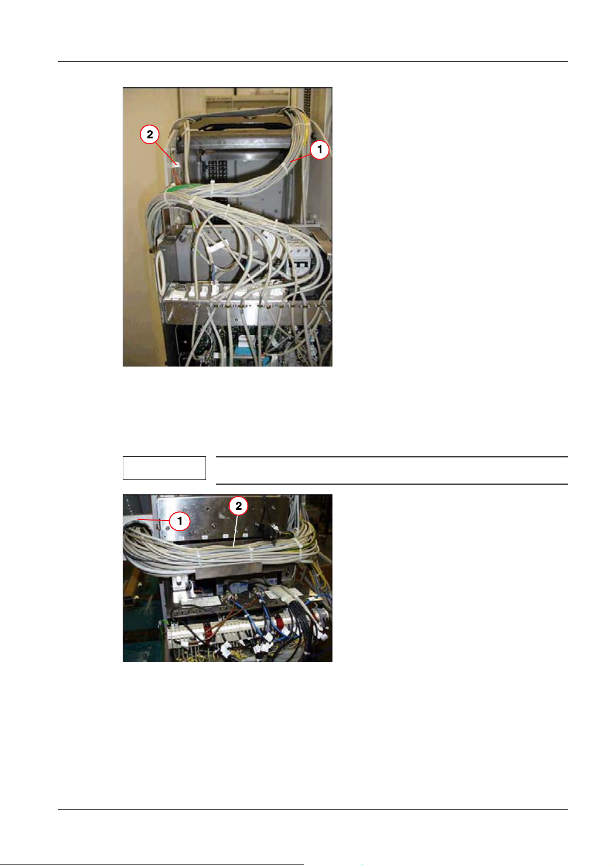
Fig. 19: Wiring
Pos. 1 Cable strand
Pos. 2 Shielding
• Run the cable strand to M2 underneath the cover (1/Fig. 19 / p. 21).
NOTE
Fig. 20: Holder on the lifting base
Pos. 1 Holder
Pos. 2 Cables
Attach the shielding (2/Fig. 19 / p. 21).
Siemens AG SPL5-330.812.01.08.02 UROSKOP ACCESS
Medical Solutions
01.06 CS PS SP
Page 21 of 90
Page 22
22 Unit carrier
• Use the supplied holder (1/Fig. 20 / p. 21) to connect the corrugated hose to the lifting
base and position the cable according to (2/Fig. 20 / p. 21).
- Take care that the corrugated hose is turned into itself, so that it lies against the lifting
base
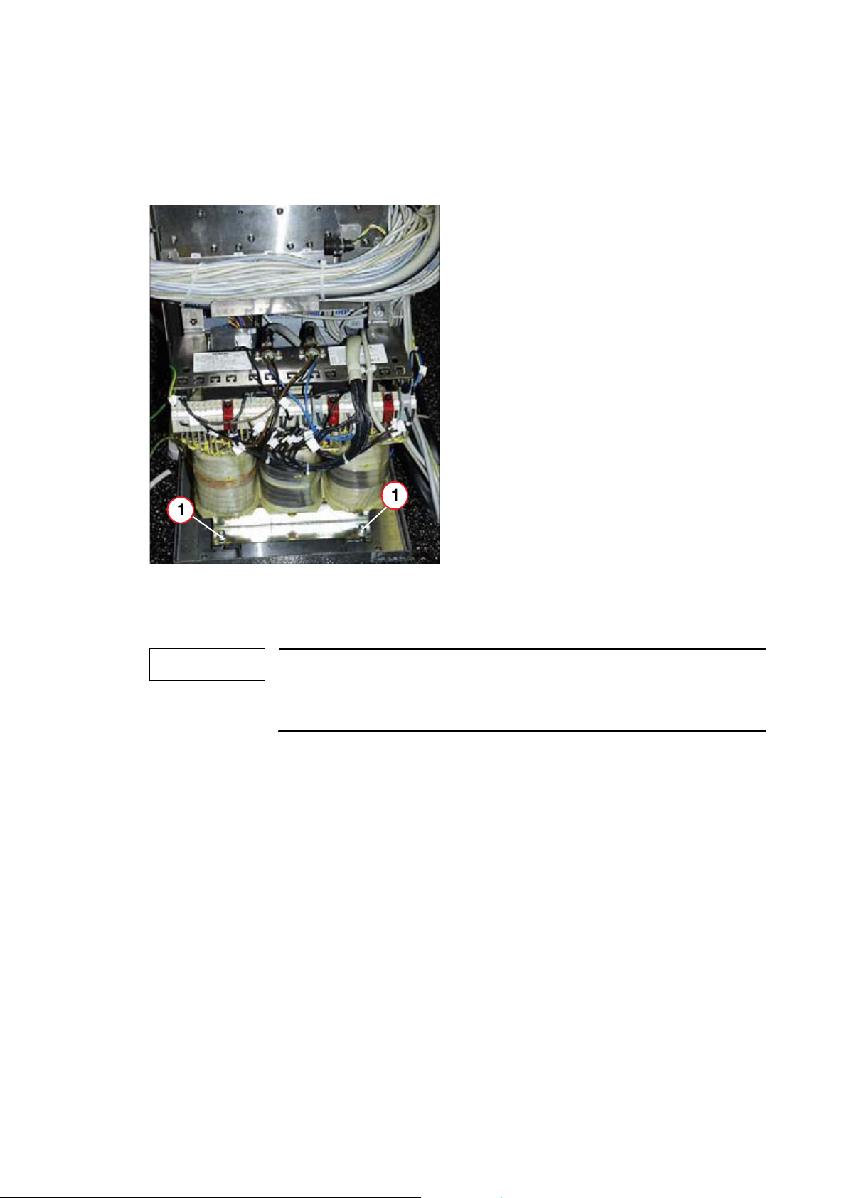
Fig. 21: Transformer T1
Pos. 1 Transformer holder
• Attach transformer T1 directly to transformer holder (1/Fig. 21 / p. 22).
NOTE
The transformer holder has a factory-installed rubber buffer.
Do not use any of the additional shims or rubber washers included
with delivery to attach transformer T1 to the transformer holder.
• Route the cable for M1 and M2 according to (Fig. 22 / p. 23), (Fig. 23 / p. 23).
UROSKOP ACCESS SPL5-330.812.01.08.02 Siemens AG
01.06 CS PS SP
Page 22 of 90
Medical Solutions
Page 23
Unit carrier 23
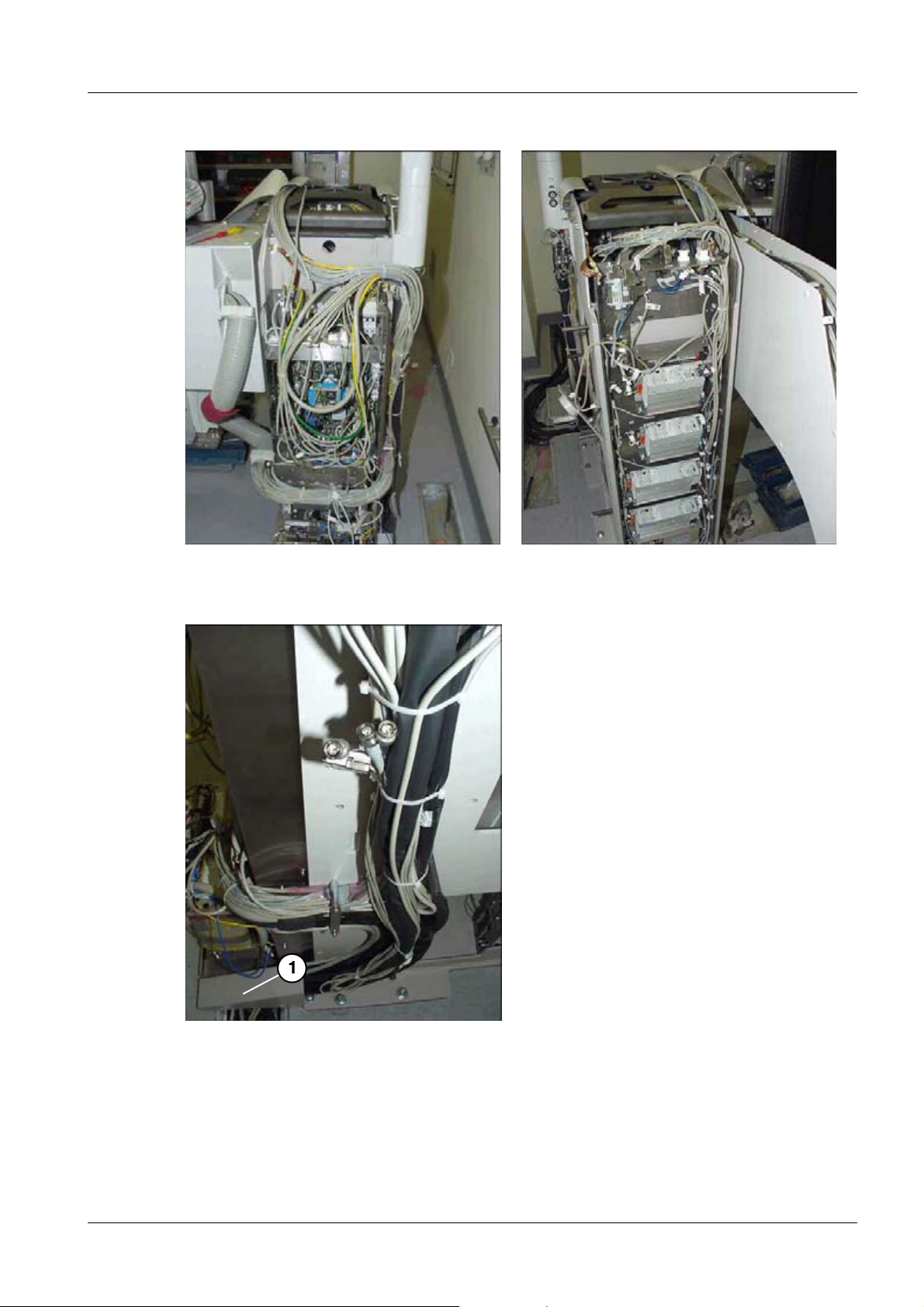
Fig. 22: Cable layout M1
Fig. 23: Cable layout M2
• Cable layout for a lateral cable lead-in according to (1/Fig. 24 / p. 23).
Fig. 24: Lateral cable layout
Pos. 1 Cable lead-in
Siemens AG SPL5-330.812.01.08.02 UROSKOP ACCESS
Medical Solutions
01.06 CS PS SP
Page 23 of 90
Page 24
24 Unit carrier
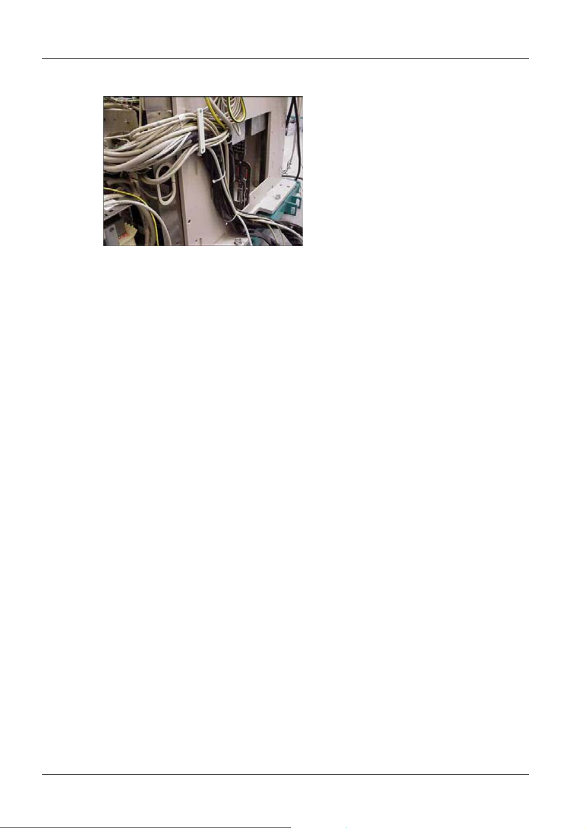
• Cable layout for the cable outlet at the back of the unit (Fig. 25 / p. 24).
Fig. 25: Cable outlet at the back of the unit
UROSKOP ACCESS SPL5-330.812.01.08.02 Siemens AG
01.06 CS PS SP
Page 24 of 90
Medical Solutions
Page 25
Unit carrier 25
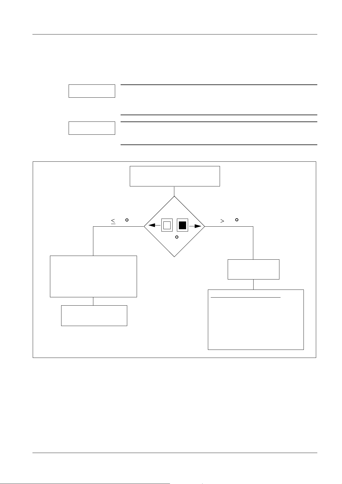
EH111509-110902-02-01
Read off Temperature Indicator
37
Record in
Test Certificate Image Quality
System Binder Reg.: 9
(not in Systems with
FLUOROSPOT Compact)
Remove
Temperature Indicator
Call SIEMENS
Only SIEMENS-engineer
Proceed per:
Installation Instructions
Monitoring Temperatur of
SIRECON Unit and
System Binder Reg.: Installation
37 C
C
37 C
Projectmanager
OPTILUX Tube System
Installation of image intensifier I.I 33/I.I. 40 0
Reading the temperature indicators on the I.I. 0
NOTE
NOTE
The image intensifier is provided with temperature indicators. Exceeding the permissible temperature can negatively influence image quality.
The basic color of the temperature indicators is white. In the case
of an excessive temperature, the inner square turns black.
• Check these temperature indicators as follows:
Fig. 26: Temperature indicator
Siemens AG SPL5-330.812.01.08.02 UROSKOP ACCESS
Medical Solutions
01.06 CS PS SP
Page 25 of 90
Page 26
26 Multileaf collimator
4Multileaf collimator
5-
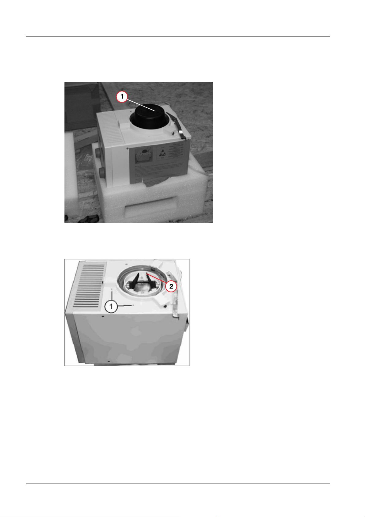
Installing the collimator 0
• Remove the protective cover from the collimator (1/Fig. 27 / p. 26) by removing the
Allen screws and threaded pins.
Fig. 27: Collimator installation
Pos. 1 Protective cover
• Remove the red transport safety screws from the collimator (1/Fig. 28 / p. 26).
Fig. 28: Collimator installation
Pos. 1 Transport safety screws
Pos. 2 Blades
• Mount the collimator on the tube assembly flange and align it (1/Fig. 29 / p. 27).
UROSKOP ACCESS SPL5-330.812.01.08.02 Siemens AG
01.06 CS PS SP
Page 26 of 90
Medical Solutions
Page 27
Multileaf collimator 27
NOTE
Fig. 29: Installing the collimator
Pos. 1 Tube assembly flange
Do not damage the collimator blades (2/Fig. 28 / p. 26).
• Connect connector M9.Z66.X1 to the back of the collimator.
- Clamp the cables with the exposed shielding braid under the strain relief device.
• Connect the KermaX cables (optional) together and store them in the tube assembly at-
tachment.
Siemens AG SPL5-330.812.01.08.02 UROSKOP ACCESS
Medical Solutions
01.06 CS PS SP
Page 27 of 90
Page 28

28 TFT monitor support arm
5TFT monitor support a rm
6-
Installing the TFT support arm 0
NOTE
NOTE
CAUTION
This section describes the delivery condition of the UROSKOP Access as of 1/2005 and relates to the TFT support arm with monitor
type DSC 1703 DC-V.
Installation of the TFT support is identical for the left and right
sides but is performed laterally reversed on the opposite side of
the lifting base.
Uncontrolled tilting of the support arm may involve risk of injury.
Proceed with extreme caution.
¹ 2 persons are necessary for installing the TFT support
arm (approx. 75 kg).
¹ The transport safety devices (1/2/Fig. 30 / p. 28) may be
removed only after the support arm has been installed on
the lifting base.
Fig. 30: Transport frame for the support arm
• In the right-side unit layout, screw the flange bolts into the bottom left thread (M8) of the
5 fastening threads on the unit connection of the TFT support arm (Fig. 33 / p. 30) if not
already installed at the factory.
UROSKOP ACCESS SPL5-330.812.01.08.02 Siemens AG
01.06 CS PS SP
Page 28 of 90
Medical Solutions
Page 29

TFT monitor support arm 29
NOTE
The 5 fastening threads are located on the back of the lifting base.
• Screw the securing nut onto the bolt (Fig. 33 / p. 30).
• Remove the holder for the TFT support arm from the transport frame (Fig. 31 / p. 29).
Fig. 31: Support arm attachment
CAUTION
The subsequently described loosening of the cylinder-head
screws results in a risk of injury.
Proceed with extreme caution.
¹ Secure the TFT support arm when loosening these
screws.
• Loosen the remaining 4 of the total of 5 cylinder-head screws M8 x 25 DIN 912
(1/Fig. 32 / p. 30) and remove them with the underlying washers 8,2 x 20 x 2.
NOTE
Ensure that the radiation warning light is not damaged, for example.
• Loosen all cylinder-head screws M8 x 25 DIN 912 from the wedge-shaped transport
holder (2/Fig. 32 / p. 30) and remove it.
Siemens AG SPL5-330.812.01.08.02 UROSKOP ACCESS
Medical Solutions
01.06 CS PS SP
Page 29 of 90
Page 30

30 TFT monitor support arm
NOTE
Follow a laterally reversed procedure for a left-side unit layout.
Fig. 32: Unit connection - transport
Fig. 33: Unit connection for the support arm
• Move the TFT support arm upward over the bolt.
NOTE
UROSKOP ACCESS SPL5-330.812.01.08.02 Siemens AG
The second person secures the support arm to prevent tipping.
Page 30 of 90
01.06 CS PS SP
Medical Solutions
Page 31

TFT monitor support arm 31
• Secure the unit connection of the TFT support arm via the 4 already removed cylin-
der-head screws M8 x 25 DIN 912 incl. washer 8,2 x 20 x 2 to the lifting base
(1/Fig. 34 / p. 31).
• Remove the bolt (Fig. 33 / p. 30).
• Screw in the fifth cylinder-head screw M8 x 25 DIN 912 incl. washer 8,2 x 20 x 2 instead
of the bolt.
NOTE
Use a level to align the unit connection (Fig. 34 / p. 31).
Fig. 34: Support arm connections
T • Tighten all 5 cylinder-head screws M8 x 25 DIN 912 with a tightening torque of 23.5 Nm
+/- 0.5 Nm.
• Secure the 5 cylinder-head screws with Loctite 221.
- Loctite 221 is included in the scope of delivery.
• Screw partial harness W650 with the interface plate onto the unit connection via 2
screws M4 x 10 DIN 912 (1/Fig. 35 / p. 32).
Siemens AG SPL5-330.812.01.08.02 UROSKOP ACCESS
Medical Solutions
01.06 CS PS SP
Page 31 of 90
Page 32

32 TFT monitor support arm
Fig. 35: Support arm connections
• Plug the cables from the TFT support arm into the connectors of the interface plate ac-
cording to their designations.
• Screw the 3 ground wires (M1.PE) onto the central ground point of module M1 via 1 lock
washer S4, 1 serrated washer A4,3 DIN 6798, and 1 screw M4 x 12, DIN 912.
- The fastening means are included in the scope of delivery.
• Plug cable M1.X518 into the corresponding connector of BUC (module M1).
• Run the 2 cables with BNC connector (Y, C) and 9-pin connector X1 to the endoscopy
interface and plug them in according to the labels.
• Fasten the cables to the fastening bolt for the back wall.
NOTE
If there is no endoscopy interface option, fasten the cable ends to
the fastening bolt so that safe operation is ensured.
• Attach connector M12.X5 with cable ties to partial cable harness W650 since it is not
used for the UROSKOP Access.
• Remove the transport safety devices from the TFT support arm (1/2/Fig. 30 / p. 28) and
store these for disassembly of the TFT support arm.
• Install the TFT flat screens according to the document “Installation instructions; TFT
Pendant system; UROSKOP Access“ of the Ondal company.
• Attach the flat screens with 4 hexagon-socket-head cap screws M4 x 16.
UROSKOP ACCESS SPL5-330.812.01.08.02 Siemens AG
01.06 CS PS SP
Page 32 of 90
Medical Solutions
Page 33

TFT monitor support arm 33
CAUTION
Risk of injury, risk of damaging the flat screen!
Insufficient attachment of the TFT monitors to the support arm can
result in injury to patients/operating personnel and damage to the
monitors.
¹ Properly attach the flat screens with 4 hexa-
gon-socket-head cap screws M4 X 16.
Fig. 36: Monitor attachment on the back
• Push the flat screen lightly together in the middle until there is no more gap.
• Position the flat screens at the same height, adjust to be parallel, and secure them via
screws.
• Close the cables of the TFT support arm according to the labels.
NOTE
The cables must not be bent or crushed during installation and
when attaching the cover.
Siemens AG SPL5-330.812.01.08.02 UROSKOP ACCESS
Medical Solutions
01.06 CS PS SP
Page 33 of 90
Page 34

34 TFT monitor support arm
• Fasten the cables via cable ties to the traverse element (Fig. 37 / p. 34).
Fig. 37: Cable attachment - back of the TFT support arm
UROSKOP ACCESS SPL5-330.812.01.08.02 Siemens AG
01.06 CS PS SP
Page 34 of 90
Medical Solutions
Page 35

Cabling 35
6Cabling
7-
General information 0
Labeling of the cable harnesses 0
• The supplied cable harnesses are labeled at the zipper hose ends as follows:
Fig. 38:
Pos. 1 Name of the cable harness
Pos. 2 Level
Pos. 3 Fixed point at which this cable harness is inserted
Pos. 4 Target designation (other cable harness end)
• Run the cable harnesses according to the fixed point designation and feed them into
the relevant cabinet from below, behind, on the left or right.
- The zipper hose must project about 10 cm into the cabinet.
NOTE
NOTE
The cables are labeled and provided with connection elements.
The high-voltage cables are to be run separately. The cables are to
be positioned so that the components can be swiveled out.
Siemens AG SPL5-330.812.01.08.02 UROSKOP ACCESS
Medical Solutions
01.06 CS PS SP
Page 35 of 90
Page 36

36 Cabling
List of fixed points 0
Cable
harness
no.
From
fixed
point
To
fixed
point
Cable
harness
cross-se
ction in
2
mm
Tube,
clear
width in
inches
Minimum
opening in
mm
Maximum
fixed point
distance in
m
Comments
1 P1 PU1 3125 2 1/2 - 3 ∅ 63-75 15 W100 tube assem-
bly/generator
2x high-voltage
cable + control
cable
2 P1 PU1 780 2 1/2 ∅ 63 15 W150 system
(I.I.)/generator
3 P1 PU1 3125 3 ∅ 75 15 W400 system
(M1)/generator
4 IS PU1 2000 2 ∅ 50 18 W600 genera-
tor/imaging system
5 CR1 P1 280 3 ∅ 75 20 W360 system/con-
trol console
6 P (MTA) IS 780 1 1/2 ∅ 38 18 W650 imaging sys-
tem/TFT support
arm
7 P1 IS 125 2 ∅ 50 18 Cable for CCD cam-
era X10
8Network
socket
R2 - - - - Delivery depends on
the manufacturer of
the paper printer
9Network
IS 140 1 14 x 10 4 Network socket
socket
10 VK EN 125 1 ∅ 10 15 Endo shelf
(optional)
Delivery length 20 m
2
(3 x 1.5 mm
)
11 VK PU1 - - - - Network supply line
12 P1 PU1 - - 45 x 15 15 Iontomat cable
Fixed point Subsystem
CR1 Monitor table
EN Endo shelf
UROSKOP ACCESS SPL5-330.812.01.08.02 Siemens AG
01.06 CS PS SP
Page 36 of 90
Medical Solutions
Page 37

Cabling 37
Fixed point Subsystem
IS Imaging system
MTA TFT monitor support
arm
P1 Unit
PU1 Generator
R2 Paper printer
VK Network distributor
box (on-site)
Fig. 39: Fixed point overview
• Feed the power cables into the cabinets from below.
• Secure the plug connections via the screws to the extent possible.
• Relieve the cables of tension, apply the shielding.
NOTE
Excess cable is to be routed in a meandering manner and not
coiled. Additional cable storage space (standard for the generator)
is provided for excess cable.
• Use 2 threaded bolts and washers (2/Fig. 40 / p. 38) to install the hangers
(1/Fig. 40 / p. 38) at the top and bottom of the side generator cover.
- Excess cable can be secured in a meandering manner to the hangers on the generator cover via cable ties (Fig. 41 / p. 38).
- The cable storage space cover is secured by the 4 threaded bolts.
Siemens AG SPL5-330.812.01.08.02 UROSKOP ACCESS
Medical Solutions
01.06 CS PS SP
Page 37 of 90
Page 38

38 Cabling
Fig. 40: Hanger - cable storage space
Fig. 41: Cable routing in the cable storage
space
UROSKOP ACCESS SPL5-330.812.01.08.02 Siemens AG
01.06 CS PS SP
Page 38 of 90
Medical Solutions
Page 39

Cabling 39
POLYDOROS SX65/80 cabling 0
Overview: cable connection and cable layout in the generator cabinet 0
- 1 Connection of the control panel
- 2 Generator power connection
- 3 System power connection
- 4 XCS connection
- 5 I.I. power supply
- 7 Connection of the rotating anode cables
- 8 Connection of high-voltage transformer H1
- 9 Connection of the high-voltage cables
- 10 Connection of the monitoring systems
- 12 hard disk
- 13 Service PC connection
- 14 Connection of the ground wire
(tube assembly, unit base)
- 15 Connection of the IONTOMAT detectors
- 16 Connection of the I.I./TV iris
- 18 Connection of the KermaX (optional)
Fig. 42: Polydoros SX
Siemens AG SPL5-330.812.01.08.02 UROSKOP ACCESS
Medical Solutions
01.06 CS PS SP
Page 39 of 90
Page 40

40 Cabling
Generator power connection 0
NOTE
The PE ground wire must be highly flexible. The armor shielding of
the power supply cable must not be used.
• Connect power supply cables L1, L2, L3, N, PE to terminal block K20 (Fig. 43 / p. 40).
- Be sure to connect them in the correct phase sequence.
Fig. 43: Power connection
CAUTION
Check the jumper at the terminals in M16.K20.
2-pole jumper for systems without an FI protective switch or N lead.
¹ In the case of systems without an FI protective switch or
N lead, the bridge is to be used (see figure below). The
bridge is located in the accessory bag.
UROSKOP ACCESS SPL5-330.812.01.08.02 Siemens AG
01.06 CS PS SP
Page 40 of 90
Medical Solutions
Page 41

Cabling 41
Connecting the rotating anode cables 0
Fig. 44: POLYDOROS SX 65/80
• Draw the rotating anode cables into the frame of the power cabinet on the right side and
run them up to the starter.
• Clamp the shielding braid of the cable to the right side of the starter under the upper
clamping clip (1/Fig. 44 / p. 41).
• Use cable ties (2/Fig. 44 / p. 41) to relieve cable tension.
• Connect the cables as follows:
Stator
cable
0 K3.R4 K31.R4
I K3.R2 K31.R2
II K3.R6 K32.R2
Starter with K3 (old version)
Starter with K31/K32 (new ver-
sion)
Connection of the Iontomat measuring chamber 0
• Connect the SDM measuring cable to D100.X28(F) (1/Fig. 45 / p. 42) and secure the
connector locking mechanism.
• Connect the Iontomat cable to D100.X33(A) (2/Fig. 45 / p. 42).
Siemens AG SPL5-330.812.01.08.02 UROSKOP ACCESS
Medical Solutions
01.06 CS PS SP
Page 41 of 90
Page 42

42 Cabling
Fig. 45: Connection of the Iontomat measuring chamber
Pos. 1 D100.X28(F)
Pos. 2 D100.X33(A)
Connection of the HV trigger/gray filter 0
• Connect the cable with plug names D190.X10 and D190.X11 to the I.I./TV iris connec-
tion (16/Fig. 42 / p. 39).
XCU cable connection 0
Fig. 46: XCU cable connection
• Connect the CAN cable with designation N10.D100.X10 on the left side of the XCU to
D100 (1/Fig. 46 / p. 42).
UROSKOP ACCESS SPL5-330.812.01.08.02 Siemens AG
01.06 CS PS SP
Page 42 of 90
Medical Solutions
Page 43

Cabling 43
Inserting the high-voltage transformer into the generator cabinet 0
Fig. 47:
• Open the bayonet closures of the support (1/Fig. 47 / p. 43).
• Relocate and fold out the support for the high-voltage transformer according to
(Fig. 47 / p. 43).
• Push the pallet with the high-voltage transformer in front of the power cabinet.
• Place the high-voltage transformer on the support.
CAUTION
Do not tilt the high-voltage transformer!
¹ Hold the transformer horizontal!
Siemens AG SPL5-330.812.01.08.02 UROSKOP ACCESS
Medical Solutions
01.06 CS PS SP
Page 43 of 90
Page 44

44 Cabling
Connecting the high-voltage cables 0
Fig. 48: Fig. 49:
• Run the high-voltage cable up to the high-voltage transformer (Fig. 48 / p. 44).
• Install the high-voltage connectors for HV cable type RH 098-5DF6 071 as follows:
- Consult the document “X-Ray Diagnostic System; Installation Instruction; High voltage cable RH 098-5DF6 071” (only necessary if the threaded rings have been loosened).
- Check the oil level in the high-voltage receptacles (approx. 1 cm). If necessary, fill
them with silicone oil AK350 (material number 17 87 035).
- Insert the high-voltage plugs in H1 as designated (Fig. 49 / p. 44).
- Tighten the union nuts and secure them with the threaded pins.
UROSKOP ACCESS SPL5-330.812.01.08.02 Siemens AG
01.06 CS PS SP
Page 44 of 90
Medical Solutions
Page 45

Cabling 45
Connecting the primary cables 0
Fig. 50:
Fig. 51:
• Carefully remove the contact protection on D220 (1/Fig. 50 / p. 45).
• Connect the ground wire clamp to H1 (2/Fig. 50 / p. 45).
• Fasten twisted leads H1.U1 and H1.V1 from the inverter modules to H1 as designated
(3/Fig. 51 / p. 45).
• Run the cable connected to D220.X41 (4/Fig. 51 / p. 45) upward to board D160 and
connect it to X44. Clamp the shielding braid at the cable end with connector X44 under
the prepared clip underneath board D100.
• Connect the X1 cable from D100 to X1 on D220 (5/Fig. 50 / p. 45).
• Clamp the shielding braid under the strain relief device.
NOTE
There must be a ground connection between the cover and
ground.
• Check the nut of the grounding bolt (7/Fig. 51 / p. 45) for firm seating and tighten it if
necessary.
• Reattach the contact protection (1/Fig. 50 / p. 45).
• Push high-voltage transformer H1 into the power cabinet and snap in the bayonet clo-
sures.
• Plug in the connection cable for the fan at X19 (+24 V; red lead - PIN A; blue lead - PIN
B).
Siemens AG SPL5-330.812.01.08.02 UROSKOP ACCESS
Medical Solutions
01.06 CS PS SP
Page 45 of 90
Page 46
46 Cabling
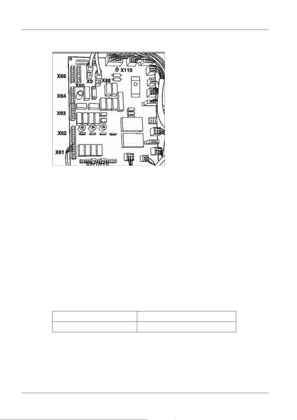
Monitoring devices and displays for radiation protection 0
Fig. 52: Power cabinet connections
• At the customer's request or if required by country-specific regulations (e.g. DHHS), the
following monitoring devices and displays can be connected in the power cabinet to
D160.X61 through X64 (Fig. 52 / p. 46):
Connecting the door contact for radiation blocking
• A door contact can be looped in series to the oil pressure switch between the following
points:
D160.X61.3 and D160.X61.4
Connecting the display lights for the radiation display
(e.g. in front of the door of the examination room)
• If an external radiation display for fluoroscopy and exposure is desired, 2 voltage-free
contacts (230 V, max. 4 A can be switched via these contacts) can be provided on
board D160 with the following connections:
- D160.X60.7-8
- D160.X60.5-6
Display occurs with pre-contact: Bridge X38.1-2 connected to D160
Display only with radiation: Bridge X38.2-3 connected to D160
Room lighting control
A control voltage (24 V~) is provided via D160.X64.5-6 for control purposes. A power
surge relay can be controlled via this.
UROSKOP ACCESS SPL5-330.812.01.08.02 Siemens AG
01.06 CS PS SP
Page 46 of 90
Medical Solutions
Page 47

Cabling 47
Control voltage (24 V~, max. 1 A)
for power surge relay:
Voltage -free normally open contact:
Bridge X8.1-2 connected to D160
Bridge X8.2-3 connected to D160
Connecting the ground wires 0
Fig. 53: Ground wire connection
• Connect the ground wires of the tube assembly in the system cabinet to the ground wire
connection points (1/Fig. 53 / p. 47) in the generator on M16.
NOTE
To avoid disturbances due to ground loops, run the ground wires
in a star pattern to the central ground wire connection point.
Siemens AG SPL5-330.812.01.08.02 UROSKOP ACCESS
Medical Solutions
01.06 CS PS SP
Page 47 of 90
Page 48

48 Cabling
Monitors in the control room 0
The following monitor types are available for selection for the control room as live and reference monitors:
1. Flat panel - Siemens DSB 1803 DC (18.1’’), S/W - 1280 x 1024 pixels
(part number 77 28 657).
2. Flat panel - Eizo Radiforce R11 (18.1’’), color - 1280 x 1024 pixels
(part number 30 99 553).
NOTE
It must be distinguished for each monitor during installation
whether the system is with/without a urodynamics interface.
Systems without a urodynamics interface 0
• The back of monitor 1 is connected via a 3-m BNC/BNC monitor cable, which is provid-
ed in the imaging system container, to the BNC outputs at the video splitters (connections R OUT, B OUT, G BAS OUT) (Fig. 59 / p. 54). The live monitor is connected to the
front video splitter and the reference monitor is connected to the back splitter.
• Monitor 2 must be connected according to the figure via a DVI adapter (part number 77
48 531) (Fig. 54 / p. 49) and a 3-m SVGA/BNC monitor cable (part number 30 79 035)
which is provided with the Eizo monitor to the BNC outputs at the video splitters (connections R OUT, B OUT, G BAS OUT, SV OUT, SH OUT) (Fig. 85 / p. 74). The live
monitor is connected to the front video splitter and the reference monitor is connected
to the back splitter.
Systems with a urodynamics interface 0
Live monitor
• The back of monitor 1 is connected via a 3-m SVGA/BNC cable (part number 30 79
035) to the PC-OUT output (SVGA) of the scan converter.
• The back of monitor 2 is connected via a DVI adapter (part number 77 48 531)
(Fig. 54 / p. 49) and a 3-m SVGA cable (part number 30 89 496) to the PC-OUT output
(SVGA) of the scan converter.
Reference monitor
• Monitors 1/2 are connected as described in chapter (Systems without a urodynamics
interface / p. 48).
NOTE
UROSKOP ACCESS SPL5-330.812.01.08.02 Siemens AG
In the case of problems with image display on the Urodynamic
workstation, the data according to the document “Installation and
Start-up; Urodynamic Interface/Scan Converter“
(SPL5-330.814.01.xx) is to be reviewed.
01.06 CS PS SP
Page 48 of 90
Medical Solutions
Page 49

Cabling 49
Explanations of the various monitor types 0
Eizo Radiforce R11
• The Eizo Radiforce R11 monitor is to be installed as a live and reference monitor in the
control room as described below.
Fig. 54: Eizo Radiforce R11 monitor (back)
Pos. 1 DVI adapter
Pos. 2 SVGA/BNC monitor cable
Pos. 3 Power cable
Pos. 4 Support bracket
Fig. 55: Eizo Radiforce R11 monitor
Siemens AG SPL5-330.812.01.08.02 UROSKOP ACCESS
Medical Solutions
01.06 CS PS SP
Page 49 of 90
Page 50

50 Cabling
Siemens DSB 1803-DC
Fig. 56: Siemens DSB 1803-DC monitor
• The Siemens DSB 1803-DC monitor is to be installed as a live and reference monitor in
the control room as described below.
• Lay the display down and then attach the separately packed monitor base to it via the 4
supplied screws as shown in the figure(Fig. 56 / p. 50).
- Be sure to remove the rear monitor base cover by pulling the recessed grip in a backward direction (see arrow position (Fig. 56 / p. 50)) prior to assembly. This cover is
already removed in the figure (Fig. 56 / p. 50).
• Replace the black rubber lip around the periphery of the display with the supplied silver
rubber lip.
• Connect the power cable and the image signal cable of the monitor to the display.
• Set the power switch to the “ON” position.
• Attach the rear cover to the monitor base.
UROSKOP ACCESS SPL5-330.812.01.08.02 Siemens AG
01.06 CS PS SP
Page 50 of 90
Medical Solutions
Page 51

Cabling 51
FLUOROSPOT Compact imaging system container 0
Fig. 57: Imaging system container
• Install the imaging system container at the location indicated in the project plan.
• Ensure a sufficient distance from the tabletop - at least 10 cm.
NOTE
Siemens AG SPL5-330.812.01.08.02 UROSKOP ACCESS
Medical Solutions
To connect the imaging system container, it is necessary to open
the cover, side wall and rear wall of the container (access to M16,
transformer, power supply connection, and interfaces).
Page 51 of 90
01.06 CS PS SP
Page 52

52 Cabling
• Position cable harness W650 of the TFT support arm with respect to the imaging sys-
tem container.
• Install cable harnesses W600 and W650 as described in the section (Cable harness
installation / p. 59).
NOTE
Strain relief is generally provided for all external cables. Cable ties
to be attached to the provided punched holes in the M16 housing
(imaging system container) are used for securing the cables. The
stripped cable shields are to be clamped under the corresponding
cable clips.
Mouse 0
• Connect the mouse to the right connection with the mouse symbol (1/Fig. 58 / p. 53).
• Provide strain relief via cable ties at the punched holes.
Network 0
• Connect the imaging system PC to the network via an unshielded twisted pair lead
(7/Fig. 58 / p. 53).
NOTE
In the event in which no network connection is initially provided,
this lead should be attached to the back wall of the imaging system
container via cable ties.
Keyboard 0
• Connect the keyboard cable to the left connection with the keyboard symbol
(2/Fig. 58 / p. 53) (next to the mouse connection) and secure the cable via cable ties.
NOTE
Use the supplied extension to extend the keyboard cable.
Laser printer connection 0
NOTE
The laser printer (paper printer) is to be connected to the hospital
network in the case of an existing network connection of the UROSKOP Access. The configuration of the paper printer is described
in document “UROSKOP ACCESS; Help-File FLC“
(SPL5-330.880.01.xx). This help file is installed on the imaging system PC during start-up.
UROSKOP ACCESS SPL5-330.812.01.08.02 Siemens AG
01.06 CS PS SP
Page 52 of 90
Medical Solutions
Page 53

Cabling 53
Back of the imaging system PC (cabling only as an example) 0
Fig. 58: Rear side of the imaging system PC (cabling shown as an example)
Pos. 1 Mouse connection
Pos. 2 Keyboard connection
Pos. 3 Connection D1 imaging system container
Pos. 4 XCS bus cable
Pos. 5 Camera connection
Pos. 6 Graphics card connection (life and reference monitor)
Pos. 7 LAN connection
Siemens AG SPL5-330.812.01.08.02 UROSKOP ACCESS
Medical Solutions
01.06 CS PS SP
Page 53 of 90
Page 54

54 Cabling
Cabling of the imaging system container 0
Fig. 59: Imaging system container cabling
Pos. 1 Monitor connections
Pos. 2 Connection points of the 400 V/440 V/480 V
voltage supply from the generator
Pos. 3 M16.K2
Pos. 4 M16D1.SK111
Fig. 60: Cabling of the imaging system
container
Pos. 1 Video splitter D233 (live image; front)
Pos. 2 Video splitter D233 (reference image; back)
Pos. 3 Live image monitor connections
Pos. 4 Reference image monitor connections
UROSKOP ACCESS SPL5-330.812.01.08.02 Siemens AG
01.06 CS PS SP
Page 54 of 90
Medical Solutions
Page 55

Cabling 55
Fig. 61: Video splitter D233
Pos. 1 Live image video splitter
Pos. 2 Reference image video splitter
NOTE
The signal for the live image is available at the front video splitter
(1/Fig. 61 / p. 55), and the signal for the reference image is avail-
able at the back video splitter (2/Fig. 61 / p. 55).
Siemens AG SPL5-330.812.01.08.02 UROSKOP ACCESS
Medical Solutions
01.06 CS PS SP
Page 55 of 90
Page 56

56 Cabling
Fig. 62: Strain relief overview
Pos. 1 Image signal cables (W650)
Pos. 2 M16.K2 (power cables for the monitors)
Pos. 3 M16.D1.SK111 (W600)
Pos. 4 M16.F1 (W600)
Pos. 5 M16.X1 (W600 + W650)
Pos. 6 M16.X2 (W650)
Pos. 7 M59.X3 (W600) XCS cable
Pos. 8 M16.PE (W600)
Pos. 9 Partial cable harness W600
Pos. 10 Partial cable harness W650 TFT support arm
NOTE
The design of the cable harnesses on the imaging system container is identical, with the exception of the number of BNC cables. Cable harness W650 has 7 coaxial cables with BNC plugs.
UROSKOP ACCESS SPL5-330.812.01.08.02 Siemens AG
01.06 CS PS SP
Page 56 of 90
Medical Solutions
Page 57

Cabling 57
Fig. 63:
Pos. 1 Power and image cables for monitors in the control room, mouse and keyboard cables, optional: Printer cables
Pos. 2 Supply of cables from unit and generator
Siemens AG SPL5-330.812.01.08.02 UROSKOP ACCESS
Medical Solutions
01.06 CS PS SP
Page 57 of 90
Page 58

58 Cabling
Board D1 (BUC) - connector overview 0
Fig. 64: PC board D1 (BUC) - connector overview
UROSKOP ACCESS SPL5-330.812.01.08.02 Siemens AG
01.06 CS PS SP
Page 58 of 90
Medical Solutions
Page 59

Cabling 59
Cable harness installation 0
W100 system (tube assembly) - POLYDOROS SX 0
System (tube
assembly)
H11.+ AP1.H1.+ High-voltage cable (+)
H11.- AP1.H1.- High-voltage cable (-)
H11.PE M16.K20.PE Ground wire
H11.1,2 D160.X61 Oil pressure switch
H11.X2 K31/K32 Rotating anode cable
KermaX Connector Dose measurement
Generator Function
W150 system (I.I.) - POLYDOROS SX 0
Generator System (I.I.) Function
D100.X28(F) D100.X1 SDM sensor
Z108.K1
Conn2/D100.X2
/M61.K1
I.I. voltage supply (zoom)
D190.X10 M8.K5 Gray filter
D190.X10 FK.X2 TV iris
Additional cables 0
NOTE
Imaging system con-
tainer
Imaging system
The subsequently listed cables are routed separately and are not
part of the cable harness.
Generator Unit (II) Function
__
D100.X33(A) M3.JK2 Iontomat cassette
FK.X1
Cable for CCD camera
(X10)
Siemens AG SPL5-330.812.01.08.02 UROSKOP ACCESS
Medical Solutions
01.06 CS PS SP
Page 59 of 90
Page 60

60 Cabling
W360 unit (M1) - control console (M11) 0
Fig. 65: Unit M1.D1 control console (M11)
Pos. 1 Control panel
Pos. 2 Tableside control (optional)
W400 system (M1) - POLYDOROS SX 0
System Generator Function
M1.F1 M16.K4 Voltage supply
M1.PE M16.PE Ground wire
M1.D1.X31 D320.X4US HW radiation release
M1.D1.X301 N10.D100.X10 CAN connection
M1.D1.X32 D160.X61 Radiation display control panel
M1.X109 D160.X9 Control panel on/off
W600 POLYDOROS SX - imaging system container 0
Polydoros SX Cable IS container Name
D320.X4S 1 M59.D100.X3 XCS connection cable
D190.X11 2 M16.D1.SK111 Sync. pulsed FL/DR
UROSKOP ACCESS SPL5-330.812.01.08.02 Siemens AG
01.06 CS PS SP
Page 60 of 90
Medical Solutions
Page 61

Cabling 61
Polydoros SX Cable IS container Name
M16.K30 3 M16.F1
M16.PE 4 M16.PE Ground wire
D160.X64 5 M16.X1 TFT radiation display
Voltage supply for the imaging
system container
W650 imaging system container - TFT support arm 0
IS container Support arm interface M12 Name
M16.K22 M12.X8 Power pack endo-switchover TFT
BS.Live 1 M12.Live 1 RGB Live TFT
BS.Ref 1 M12.Ref 1 RGB Ref TFT
M16.X1 M12.H1 TFT radiation display
M16.BNC1 Mon. switchover URO Urodynamic BAS (B/W)
Data printer connection (label printer, optional) 0
NOTE
• Connect the 9-pole connector on the side to connection X62 of the XCU.
The label printer described here is used for printing patient-related
doses.
Siemens AG SPL5-330.812.01.08.02 UROSKOP ACCESS
Medical Solutions
01.06 CS PS SP
Page 61 of 90
Page 62

62 Cabling
Remote control panel cabling (optional) 0
Fig. 66: Control panel
• Open the back cover of the control panel and connect the cable coming from module
M1 (unit) as labeled (Fig. 67 / p. 62).
Fig. 67: Cable layout in the control panel Fig. 68: Cable layout in the control panel
NOTE
The cable layout in the control panel depends on the cable supply
(1/Fig. 67 / p. 62); (1/Fig. 68 / p. 62).
• Ensure that the cables are free of strain.
• Connector M11.X2 must be situated inside the control panel and may not be routed to-
ward the outside.
• Connect the second tableside control (optional), if available, and place it on the control
panel (2/Fig. 67 / p. 62); (2/Fig. 68 / p. 62).
UROSKOP ACCESS SPL5-330.812.01.08.02 Siemens AG
01.06 CS PS SP
Page 62 of 90
Medical Solutions
Page 63

Cabling 63
• Subsequently reattach the cover.
NOTE
The tableside control on the unit (coding A) and the tableside control on the control panel (coding B, optional) are labeled differently
(see document “Wiring Diagram“ [SPL5-330.844.91.01.02]; tableside control bridge overview).
Siemens AG SPL5-330.812.01.08.02 UROSKOP ACCESS
Medical Solutions
01.06 CS PS SP
Page 63 of 90
Page 64

64 Cabling
Installing the endo shelf (optional) 0
NOTE
The installation of the endo shelf depends on the layout of the
UROSKOP Access (left/right-hand version). The differences between the left/right-hand version are shown in the figures on the
following pages.
Fig. 69: Endo shelf installation
Pos. 1 Ground wire
Fig. 70: Endo shelf installation
Pos. 1 Cable lead-in
• Prior to assembly of the shelf, the ground wire (1/Fig. 69 / p. 64) and the supplied
mm2
20-meter cable (3 x 1.5
(1/Fig. 71 / p. 64). The cable lead-in is shown in (1/Fig. 70 / p. 64).
) must be passed through the flange tube
• After the cables are led in, the flange tube (1/Fig. 71 / p. 64) is fastened to the shelf bot-
tom (Fig. 70 / p. 64) via the supplied screws (M6 x 25) and washers.
Fig. 71: Endo shelf installation
Pos. 1 Flange tube
Fig. 72: Endo shelf installation
• Check the grounding bolts and if necessary tighten these (see arrows) (Fig. 72 / p. 64).
UROSKOP ACCESS SPL5-330.812.01.08.02 Siemens AG
01.06 CS PS SP
Page 64 of 90
Medical Solutions
Page 65

Cabling 65
NOTE
Use increased caution when assembling the shelf. Make sure that
the led-in power cable and the ground wire are not crushed or
damaged.
Right-hand version of the endoscopy shelf 0
NOTE
The figure shows the installation of the right-hand version
(Fig. 73 / p. 65).
Fig. 73: Right-hand version of the endo shelf Fig. 74: Right-hand version of the endo shelf
Pos. 1 Unit connection
• Use the supplied screws M8 x 25 DIN 912 and washers to mount the unit connection
(1/Fig. 74 / p. 65) to the back of the lifting base.
T - Tighten the 5 screws with a torque of 25 Nm.
Left-hand version of the endoscopy shelf 0
NOTE
The figure shows the installation of the left-hand version
(Fig. 75 / p. 66).
Siemens AG SPL5-330.812.01.08.02 UROSKOP ACCESS
Medical Solutions
01.06 CS PS SP
Page 65 of 90
Page 66

66 Cabling
Fig. 75: Left-hand version of the endo shelf Fig. 76: Left-hand version of the endo shelf
Pos. 1 Unit connection
• Use the supplied screws M8 x 25 DIN 912 and washers to mount the unit connection
(1/Fig. 76 / p. 66) to the back of the lifting base.
T - Tighten the 5 screws with a torque of 25 Nm.
Installing the endo shelf on the unit carrier 0
Fig. 77: Endoscopy shelf with endoscopy interface
• Route the connection cable (20 m) through the unit connection of the unit carrier
(1/Fig. 77 / p. 66); (2/Fig. 77 / p. 66).
• Connect the ground wire to the grounding point of the lifting base.
UROSKOP ACCESS SPL5-330.812.01.08.02 Siemens AG
01.06 CS PS SP
Page 66 of 90
Medical Solutions
Page 67

Cabling 67
• Install the shelf in the mount (1/Fig. 77 / p. 66) and secure it with the threaded pin
(2/Fig. 77 / p. 66).
• Install the emergency shutdown plate in the back wall of the unit and secure it tightly via
screws (3/Fig. 77 / p. 66).
NOTE
The connection of the multiple socket outlet (4/Fig. 77 / p. 66) and
the on-site connection of the 20-m connection cable (3 x 1.5 mm
2
may only be performed by an authorized specialist and must follow the country-specific regulations provided by the operator.
This may not be performed at the system contactor (see document
“Planning Guide; System; UROSKOP Access (e) “
[SPL5-330.891.01.xx]).
Outside Germany, the supplied multiple socket outlet may be replaced by a multiple socket outlet meeting the country-specific
regulations. This multiple socket outlet is to be procured locally.
)
Siemens AG SPL5-330.812.01.08.02 UROSKOP ACCESS
Medical Solutions
01.06 CS PS SP
Page 67 of 90
Page 68

68 Cabling
Endoscopy interface connection (optional) 0
Fig. 78: Endoscopy interface connections
Pos. 1 FBAS-In: Composite video from the scan converter (imaging system container) (BNC)
Pos. 2 C-Out: S-Video (C) to the monitor (BNC)
Pos. 3 Y-Out: S-Video (Y) to the monitor (BNC)
Pos. 4 X3: Control signals from M1 (BUC) (15-pole D-sub)
Pos. 5 X2: Power input (230 V AC)
Pos. 6 X1: Serial connection (RS232) to the monitor (9-pole D-sub)
Pos. 7 Ground wire
UROSKOP ACCESS SPL5-330.812.01.08.02 Siemens AG
01.06 CS PS SP
Page 68 of 90
Medical Solutions
Page 69

Cabling 69
Connecting the foot switch 0
• Connect the fluoroscopy foot switch (Fig. 79 / p. 69) to M1.X9 according to the cable la-
beling.
Fig. 79: Fluoroscopy foot switch connection
• Connect the system foot switch (optional) to M1.D1.X303 according to the cable label-
ing (Fig. 80 / p. 69).
Fig. 80: System foot switch
• For the purpose of strain relief/fastening, secure the foot switch cable to the cable har-
ness (2/Fig. 20 / p. 21) via cable ties.
Siemens AG SPL5-330.812.01.08.02 UROSKOP ACCESS
Medical Solutions
01.06 CS PS SP
Page 69 of 90
Page 70

70 Cabling
ASPIA imaging system container 0
NOTE
FLUOROSPOT compact imaging systems as well as ASPIA imaging systems are installed in the installed base.
Fig. 81: ASPIA container
Pos. 1 Keyboard connection
Pos. 2 Mouse connection
Pos. 3 License dongle
Pos. 4 Network connection
Pos. 5 Connection point of the ground wire of the ASPIA PC
UROSKOP ACCESS SPL5-330.812.01.08.02 Siemens AG
01.06 CS PS SP
Page 70 of 90
Medical Solutions
Page 71

Cabling 71
• Install the imaging system container at the location specified in the project plan.
• Ensure a sufficient distance from the tabletop - at least 10 cm.
NOTE
To connect the imaging system container, it is necessary to open
the cover, side wall and rear wall of the container (access to M16,
transformer, network connection, and interfaces).
• Position cable harness W650 of the TFT support arm with respect to the imaging sys-
tem container.
• Install cable harnesses W600 and W650 as described in the section (Cable harness
installation / p. 59).
NOTE
Strain relief is generally provided for all external cables. Cable ties
to be attached to the provided punched holes in the housing (M16,
imaging system container) are used for securing the cables. The
stripped cable shields are to be clamped under the corresponding
cable clips.
Mouse 0
• Connect the mouse to the right connection with the mouse symbol (2/Fig. 81 / p. 70).
• Use cable ties at the punched holes in the imaging system container for strain relief.
Network 0
• Connect the PC to the local network via an unshielded twisted pair lead
(4/Fig. 81 / p. 70).
- The cable is included in the scope of delivery.
NOTE
In the event in which no network connection is initially provided,
this lead should be attached to the back wall of the imaging system
container via cable ties.
Keyboard 0
• Connect the keyboard cable to the left connection with the keyboard symbol and se-
cure the cable via cable ties (1/Fig. 81 / p. 70).
NOTE
Use the supplied extension to extend the keyboard cable.
Siemens AG SPL5-330.812.01.08.02 UROSKOP ACCESS
Medical Solutions
01.06 CS PS SP
Page 71 of 90
Page 72

72 Cabling
Laser printer connection 0
• The following options are possible for connecting the laser printer (paper printer):
- Integration of the printer as a network printer in the local hospital/office network;
- LPT1 connection (parallel interface to the back of the PC);
- Connection directly to the PC network connection (RJ45 connection on the back of
the PC; (4/Fig. 81 / p. 70)).
NOTE
Detailed descriptions regarding the connection of the paper printer are provided in document “Installation and Start-up; Installation
of options“ (SPL5-330.814.02.xx).
Back of the imaging system PC 0
NOTE
The cabling shown here is only an example.
Fig. 82: Cabling at the back of the PC
Pos. 1 Monitor 1 (live)
Pos. 2 Monitor 2 (reference)
Pos. 3 Radiation trigger hardware
Pos. 4 TV camera
Pos. 5 XCS connection (M59.X3)
UROSKOP ACCESS SPL5-330.812.01.08.02 Siemens AG
01.06 CS PS SP
Page 72 of 90
Medical Solutions
Page 73

Cabling 73
Cabling of the imaging system container 0
Fig. 83: Imaging system container cabling
Pos. 1 BNC 1: Urodynamics option
Pos. 2 Connection point of the ground wire of the
ASPIA PC
Pos. 3 Connection point of the ground wire of the
generator voltage supply
Fig. 84: Imaging system container cabling
Pos. 1 Monitor connections
Pos. 2 Connection points of the 400 V/440 V/480 V
voltage supply from the generator
Pos. 3 M16.K2
Pos. 4 M16D1.SK111
Siemens AG SPL5-330.812.01.08.02 UROSKOP ACCESS
Medical Solutions
01.06 CS PS SP
Page 73 of 90
Page 74

74 Cabling
Fig. 85: Imaging system container cabling
Pos. 1 Routing of image signal cables to the con-
tainer
Pos. 2 Supply of the power cables
Fig. 86: Cabling of the imaging system
container
Pos. 1 Video splitter D233 (live image; front)
Pos. 2 Video splitter D233 (reference image; back)
Pos. 3 Live image monitor connections
Pos. 4 Reference image monitor connections
UROSKOP ACCESS SPL5-330.812.01.08.02 Siemens AG
01.06 CS PS SP
Page 74 of 90
Medical Solutions
Page 75

Cabling 75
Fig. 87: Video splitter D233
Pos. 1 Live image video splitter
Pos. 2 Reference image video splitter
NOTE
The live image is available at the front video splitter
(1/Fig. 87 / p. 75), and the reference image is available at the back
video splitter (2/Fig. 87 / p. 75).
Siemens AG SPL5-330.812.01.08.02 UROSKOP ACCESS
Medical Solutions
01.06 CS PS SP
Page 75 of 90
Page 76

76 Cabling
Fig. 88: Strain relief overview
Pos. 1 Image signal cables (W650)
Pos. 2 M16.K2 (power cables for the monitors)
Pos. 3 M16.D1.SK111 (W600)
Pos. 4 M16.F1 (W600)
Pos. 5 M16.X1 (W600 + W650)
Pos. 6 M16.X2 (W650)
Pos. 7 M59.X3 (W600) XCS cable
Pos. 8 M16.PE (W600)
Pos. 9 Partial cable harness W600
Pos. 10 Partial cable harness W650 TFT support arm
NOTE
The design of the cable harnesses on the imaging system container is identical, with the exception of the number of BNC cables.
Cable harness W650 has 7 coaxial cables with BNC plugs.
UROSKOP ACCESS SPL5-330.812.01.08.02 Siemens AG
01.06 CS PS SP
Page 76 of 90
Medical Solutions
Page 77

Cabling 77
Fig. 89:
Pos. 1 Power and image cables for monitors in the control room, mouse and keyboard cables, optional: Printer cables
Pos. 2 Supply of cables from unit and generator
Siemens AG SPL5-330.812.01.08.02 UROSKOP ACCESS
Medical Solutions
01.06 CS PS SP
Page 77 of 90
Page 78

78 Final work steps (covers)
7Final work steps (covers)
8-
Covers for the imaging system container 0
• Attach the cover and side and rear panels of the imaging system container.
Fig. 90: Back of the imaging system container
• Use two Allen screws (M 4 x 16) instead of the cover screws to attach the wall spacer
bracket (Fig. 90 / p. 78).
NOTE
This bracket must never be used as a carrying handle.
• Push the imaging system container against the wall as far as the bracket allows.
Fig. 91: Fig. 92:
NOTE
The fastening screws for the covers are located in a plastic bag attached to the corresponding cover.
UROSKOP ACCESS SPL5-330.812.01.08.02 Siemens AG
01.06 CS PS SP
Page 78 of 90
Medical Solutions
Page 79

Final work steps (covers) 79
• Install the covers in the sequence shown below.
• Attach the cover to the I.I. at the bottom (Fig. 91 / p. 78).
- For installation, move the unit into the +90° position. Fasten the image intensifier cover with 6 cover screws and tighten the screws in the 0° position of the unit.
NOTE
Do not insert the cover screws through the cover since this would
cause the image intensifier collision protection to be permanently
in operation (Fig. 92 / p. 78).
• After installation, check for proper functioning of the collision protection in all unit posi-
tions by lifting the image intensifier cover.
Unit carrier cover plate
• Use the supplied Allen screws to attach the cover plate (1/Fig. 93 / p. 79)) to the unit
carrier.
Fig. 93: Unit carrier cover plate
Pos. 1 Cover plate
Back of the unit carrier
• Snap on the rear unit carrier cover. It is secured after installation of the upper unit carri-
er cover (Fig. 94 / p. 80).
Siemens AG SPL5-330.812.01.08.02 UROSKOP ACCESS
Medical Solutions
01.06 CS PS SP
Page 79 of 90
Page 80

80 Final work steps (covers)
Fig. 94: Rear unit carrier cover
Tower cover
Fig. 95: Tower cover
Pos. 1 Cover
• Move the table laterally toward the operator to its end position.
• Two persons must carefully insert the cover between the cover plate and the tube car-
riage (1/Fig. 95 / p. 80).
• Carefully insert the tower cover underneath the tube carriage (1/Fig. 96 / p. 81).
UROSKOP ACCESS SPL5-330.812.01.08.02 Siemens AG
01.06 CS PS SP
Page 80 of 90
Medical Solutions
Page 81

Final work steps (covers) 81
Fig. 96: Tower cover
Pos. 1 Cover
• Attach the tower cover via the supplied screws (1/Fig. 97 / p. 81).
NOTE
Fig. 97: Securing the tower cover
Pos. 1 Screws
Pos. 2 Rubber seal
Make sure that the rubber seal is properly seated on the covers
(2/Fig. 97 / p. 81).
Front unit carrier cover
• Insert the unit carrier cover (1/Fig. 98 / p. 82) and fasten it via the supplied screws.
Siemens AG SPL5-330.812.01.08.02 UROSKOP ACCESS
Medical Solutions
01.06 CS PS SP
Page 81 of 90
Page 82

82 Final work steps (covers)
Fig. 98: Front unit carrier cover
Pos. 1 Unit carrier cover
Top unit carrier cover
NOTE
To fasten the upper unit carrier cover, the tabletop must be folded
up.
• Carefully insert the upper unit carrier cover (1/Fig. 99 / p. 82) and fasten it via Allen
screws.
• Fasten the rear unit carrier cover.
- Secure the cover on the bottom with cover screws (1/Fig. 94 / p. 80).
- Secure the cover on the top with Allen screws (2/Fig. 94 / p. 80) by inserting the Allen
screws through the upper unit carrier cover and the rear unit carrier cover.
Fig. 99: Top unit carrier cover
Pos. 1 Unit carrier cover
Additional covers
• Fasten the tube carriage cover (1/Fig.100/p.83) with cover screws.
UROSKOP ACCESS SPL5-330.812.01.08.02 Siemens AG
01.06 CS PS SP
Page 82 of 90
Medical Solutions
Page 83

Final work steps (covers) 83
Fig. 100: Tube carriage cover
Fig. 101: Inserting the cover rail Fig. 102: Inserting the cover rail
• Laterally insert the cover rail (1/Fig. 101 / p. 83) and (1/Fig. 102 / p. 83).
NOTE
Fig. 103: Transverse unit cover Fig. 104: Transverse table drive
Observe the position of the silicone strip. (2/Fig. 102 / p. 83)
• Insert the unit carrier transverse cover (1/Fig.103/p.83) in the transverse table drive
(Fig.104/p.83) and fasten it with cover screws.
Siemens AG SPL5-330.812.01.08.02 UROSKOP ACCESS
Medical Solutions
01.06 CS PS SP
Page 83 of 90
Page 84

84 Final work steps (covers)
NOTE
Only the short cover screws included in the delivery may be used
to attach the cover rail.
UROSKOP ACCESS SPL5-330.812.01.08.02 Siemens AG
01.06 CS PS SP
Page 84 of 90
Medical Solutions
Page 85

Final work steps (covers) 85
Lifting base covers 0
Fig. 105: Side lifting base cover Fig. 106: Side lifting base cover
Siemens AG SPL5-330.812.01.08.02 UROSKOP ACCESS
Medical Solutions
01.06 CS PS SP
Page 85 of 90
Page 86

86 Final work steps (covers)
• Attach the side covers to the lifting base (1/Fig. 105 / p. 85) and (1/Fig.106/p.85).
Fig. 107: Foot switch cable Fig. 108: Back cover panel
Pos. 1 Emergency shutdown plate
Pos. 2 Lifting base cover
• Lead the cable of the foot switch laterally out of the cover (1/Fig.107/p.86).
• Install the emergency shutdown plate (1/Fig. 108 / p. 86) in the rear panel and secure it
with screws.
• Screw on the cover of the lifting base (2/Fig.108/p.86).
• Attach the cover of the lifting base at the locations marked in (Fig.109/p.87). Use the
cover screws M4 x 20 supplied for this purpose.
UROSKOP ACCESS SPL5-330.812.01.08.02 Siemens AG
01.06 CS PS SP
Page 86 of 90
Medical Solutions
Page 87

Final work steps (covers) 87
Fig. 109: Lifting base cover
• Attach the elbow rests at the foot end of the table and fold them in (1/Fig. 111 / p. 87).
Fig. 110: Elbow rest installation
Pos. 1 Elbow rests
NOTE
The elbow rests must not automatically unfold when the unit is tilted (1/Fig.110/p.87).
Adjustment is performed using an Allen wrench on the bottom
side of the elbow rests (2/Fig. 111 / p. 87).
Fig. 111: Elbow rest installation
• Attach all accessories to the unit and check them for damage and proper functioning.
• Pack the unit with the enclosed covering film if start-up/use is delayed because of build-
ing construction work, for example.
Siemens AG SPL5-330.812.01.08.02 UROSKOP ACCESS
Medical Solutions
01.06 CS PS SP
Page 87 of 90
Page 88

88 Changes to Previous Version
8Changes to Previous Version
9-
Chapter 1 • Section (Required documents / p. 5) completely revised
• Section (Room preparations / p. 6) completely revised (transform-
er trough added)
• Section (Safety information / p. 7) completely revised
• Section (Product-specific notes / p. 7): notes and safety informa-
tion added
• Section (Completing the installation certificate / p. 7) revised
(print number added; information stating that the certificate is to
be provided to the corresponding office)
• Section (Tolerance data / p. 8): Bullet point added as note
• Section (Abbreviations / p. 8): TV added
Chapter 2
Chapter 3
• 1. Section deleted because it was provided twice in the document
• Section (Accessories for the lifting base / p. 9): dowel designation
changed
• Section title “Installing the transport frame on the lifting base“:
changed to (Installing the transport rollers on the lifting
base / p. 10)
• Section (Positioning and installing the lifting base / p. 11): dowel
designations changed; first bullet point: Link to image added; in
the bullet point “to remove the transport safety device from the lifting base, unscrew the Allen screws...“: link to the image changed;
the note “the transport safety device can be relieved..“ added; the
bullet point “to remove the transport safety device...“ deleted; the
note “the transformer trough may only be installed on...“ added
• Section (Installation on the lifting base / p. 17): safety information
added; the note “The collimator is delivered separately...“ added
as a separate note; subpoint a) formatted as a note
• Section (Installation of power supply module (M1) / p. 19): the text
“the layout (connection overview)“ revised; bullet points 3/4 added
• Section (Wiring of M1/M2 / p. 20) reformatted; the note “do not
use any of the additional shims...“ added.
Chapter 4
Chapter 5
UROSKOP ACCESS SPL5-330.812.01.08.02 Siemens AG
• Section (Installing the collimator / p. 26): first bullet point revised;
the note “do not damage the collimator blades“ repositioned in the
chapter; 4th bullet point revised
• Section (Installing the TFT support arm / p. 28): bullet point 1 re-
vised; the note “the 5 fastening threads...“ added; the note “ensure that the radiation warning light...“ revised; document
reference in the bullet point “install the TFT flat screens...“ revised; risk information added; (Fig. 37 / p. 34): new figure
Page 88 of 90
01.06 CS PS SP
Medical Solutions
Page 89

Changes to Previous Version 89
Chapter 6 • Section (List of fixed points / p. 36): completely revised; list of ab-
breviations for fixed points added; cable storage space information added to the note; last bullet point (cable storage space)
added; (Fig. 39 / p. 37)/(Fig. 40 / p. 38)/(Fig. 41 / p. 38) new
• Section (Connection of the Iontomat measuring chamber / p. 41):
second bullet point corrected; (Fig. 45 / p. 42) legend corrected
• Section (Monitoring devices and displays for radiation
protection / p. 46): “connecting the display lights for the radiation
display“ revised; “room lighting control“ revised
• Section (Monitors in the control room / p. 48): monitor no 1 delet-
ed
• Section (Systems without a urodynamics interface / p. 48): first
bullet point “monitors no. 1/2“ changed to “monitor no. 1“; second
bullet point “monitor no. 3“ changed to “monitor no. 2“
• Section (Systems with a urodynamics interface / p. 48): under
“live monitor“ in the first bullet point “monitor no. 1/2“ changed to
“monitor no. 1“, in the second bullet point “monitor no. 3“ changed
to “monitor no. 2“; under “reference monitor“ “monitors no. 1/2/3“
changed to “monitors no. 1/2“; note revised
• Section (FLUOROSPOT Compact imaging system
container / p. 51): first note revised
• Section (Mouse/p.52): first bullet point revised
• Section (Network / p. 52): note revised
• Section (Keyboard / p. 52): bullet point revised
• Section “Laser camera connection“ completely revised and re-
named to (Laser printer connection / p. 52)
• Section (Back of the imaging system PC (cabling only as an
example) / p. 53): key of (Fig. 58 / p. 53) changed
• Section (Cabling of the imaging system container / p. 54):
(Fig. 87 / p. 75)/(Fig. 86 / p. 74) new; first note revised;
(Fig. 88 / p. 76): legend changed
• Section (W150 system (I.I.) - POLYDOROS SX / p. 59): Cables
with the function camera cable and Iontomat cassette were deleted from the overview and listed as “additional cables“
• Section (Additional cables / p. 59) added
• Section (W650 imaging system container - TFT support
arm / p. 61): data printer information provided as a separate sec-
tion (Data printer connection (label printer, optional) / p. 61)
• Section (Remote control panel cabling (optional) / p. 62): re-
named; first bullet point revised; second note revised; the bullet
point “connector M11.X2 must be situated...“ new
Siemens AG SPL5-330.812.01.08.02 UROSKOP ACCESS
Medical Solutions
01.06 CS PS SP
Page 89 of 90
Page 90

90 Changes to Previous Version
Chapter 6 • Section “Installing the endo shelf“ renamed to (Installing the endo
shelf (optional) / p. 64)
• Section “Endoscopy shelf with endoscopy interface“: renamed to
(Installing the endo shelf on the unit carrier / p. 66); listed under
(Installing the endo shelf (optional) / p. 64) as a section; note re-
vised
• Section (Endoscopy interface connection (optional) / p. 68): foot
switch deleted and included as a separate section (Connecting
the foot switch / p. 69)
• Section (ASPIA imaging system container / p. 70): first note re-
vised; the note “to connect the imaging system container...“ revised
• Section (Mouse / p. 71): the first two bullet points were combined
and revised
• Section (Network / p. 71): first bullet point revised; note revised
• Section (Keyboard / p. 71): first bullet point revised
• The section “Laser camera connection“ renamed to (Laser printer
connection / p. 72); completely revised
Chapter 7
• Section (Cabling of the imaging system container / p. 73):
(Fig. 86 / p. 74)/(Fig. 87 / p. 75) new; the note “the live image is
available...“ revised; (Fig. 88 / p. 76): legend changed
• Section (Covers for the imaging system container / p. 78): The
bullet point “Use the supplied Allen screws...“ revised; “back of the
unit carrier“ figure new; installation of the“upper unit carrier cover“
revised; highlighted text “additional covers“ added
UROSKOP ACCESS SPL5-330.812.01.08.02 Siemens AG
01.06 CS PS SP
Page 90 of 90
Medical Solutions
 Loading...