

Page 1

Preface, Contents
SIMATIC
TD 200
Operator Interface
User Manual
This manual has the order number:
6ES7272-0AA00-8BA0
Product Overview and Installation
Configuring the TD 200
Operating the TD 200
Creating Sample Programs
Appendices
Specifications and Reference
Multiple CPU Configurations
Troubleshooting
TD 200 Parameters and
Messages
1
2
3
4
A
B
C
D
10/99
Edition 5
Index
Page 2

Notes on Safety
!
!
!
This manual contains notices which you should observe to ensure your own personal safety, as
well as to protect the product and connected equipment. These notices are highlighted in the
manual by a warning triangle and are marked as follows according to the level of danger:
Danger
indicates that death, severe personal injury or substantial property damage will result if proper
precautions are not taken.
Warning
indicates that death, severe personal injury or substantial property damage can result if proper
precautions are not taken.
Caution
indicates that minor personal injury or property damage can result if proper precautions are not
taken.
Note
draws your attention to particularly important information on the product, handling the product,
or to a particular part of the documentation.
Qualified Personnel
Correct Usage
!
Trademarks
The reproduction, transmission or use of this document or its
contents is not permitted without express written authority.
Offenders will be liable for damages. All rights, including rights
created by patent grant or registration of a utility model or design, are
reserved.
Siemens AG
Bereich Automatisierungs- und Antriebstechnik
Geschaeftsgebiet Industrie-Automatisierungssysteme
Postfach 4848, D- 90327 Nuernberg
Only qualified personnel should be allowed to install and work on this equipment. Qualified
persons are defined as persons who are authorized to commission, to ground, and to tag circuits,
equipment, and systems in accordance with established safety practices and standards.
Note the following:
Warning
This device and its components may only be used for the applications described in the catalog or
the technical description, and only in connection with devices or components from other
manufacturers which have been approved or recommended by Siemens.
This product can only function correctly and safely if it is transported, stored, set up, and
installed correctly, and operated and maintained as recommended.
SIMATICR, SIMATIC NETR and SIMATIC HMIR are registered trademarks of
SIEMENS AG.
Third parties using for their own purposes any other names in this document which refer to trademarks might infringe upon the rights of the trademark owners.
Disclaimer of LiabilityCopyright Siemens AG 1995 All rights reserved
We have checked the contents of this manual for agreement with the
hardware and software described. Since deviations cannot be precluded entirely , we cannot guarantee full agreement. However, the
data in this manual are reviewed regularly and any necessary corrections included in subsequent editions. Suggestions for improvement are welcomed.
E Siemens AG 1995
Subject to technical change.
Siemens Aktiengesellschaft 6ES7272-0AA00-8BA0
Page 3

Preface
Purpose
The
SIMATIC TD 200 Operator Interface User Manual
reference manual that describes the operation of the TD 200 Operator Interface
Module with an S7-200 programmable logic controller.
Audience
This manual is designed for engineers, programmers, and maintenance personnel
who have a general knowledge of programmable logic controllers and operator
interfaces.
Scope of This Manual
This manual describes the operation of version 1.1 and later of the TD 200. This
release includes new features and other operational enhancements.
Release Notes
Version 1.1 of the TD 200 includes the following new features:
Supports real (floating-point) numbers
is a combination user and
Provides password protection for editable variables and for the Menu mode of
operation
Supports multiple parameter blocks in a single S7-200 CPU (with a setup menu
for entering the V memory address)
Supports 19.2 Kbaud communication rate (with a setup menu for changing the
baud rate)
Sets a bit in the parameter block every time an arrow key is pressed, thus
allowing your program to have more control of the TD 200
Includes an alternative character set for creating bar charts
Other enhancements (such as using any key-not just the ESC key-to cancel the
scrolling of the messages, or using SHIFT-ENTER to set a variable to 0) either
improve the performance of the TD 200 or make it easier to use. For example, you
can now use the SHIFT-UP/DOWN arrow keys to perform a
character-by-character edit of a variable that is embedded in a message.
Version 1.2 of the TD 200 includes the following new features:
Corrects problems with multi-master networks
Makes the editors more consistent
For upgrades to version 1.2 of the TD 200, contact your distributor.
SIMA TIC TD 200 Operator Interface
C79000-G7076-C205-05
iii
Page 4

Preface
Agency Approvals
The SIMATIC S7-200 series meets the standards and regulations of the following
agencies.
Underwriters Laboratories, Inc.:
UL 508 Listed (Industrial Control Equipment)
Canadian Standards Association: CSA C22.2 Number 142 Certified
(Process Control Equipment)
European Community EMC Directive 89/336/EEC and
Low Voltage Directive 73/23/EEC
How to Use This Manual
If this is your first experience using an operator interface, read the entire manual. If
you are an experienced user, refer to the Table of Contents or Index to find specific
information.
Related Information
Refer to the following documentation for more detailed information about selected
topics:
SIMATIC S7-200 Programmable Controller System Manual:
information about installing and programming the S7-200 Micro PLCs, including
the following topics:
– Installing and wiring the S7-200 CPU and expansion I/O modules, and
installing the STEP 7-Micro/WIN software
– Designing and entering a program
– Understanding features of the CPU, such as data types and addressing
modes, the CPU scan cycle, password-protection, and network
communication
This manual also includes descriptions and examples for the programming
instructions, typical execution times for the instructions, and the data sheets for
the S7-200 equipment.
SIMATIC STEP 7-Micro/DOS User Manual:
STEP 7-Micro/DOS programming software package for the SIMATIC S7-200
series of programmable logic controllers.
describes how to use the
provides
iv
SIMA TIC TD 200 Operator Interface
C79000-G7076-C205-05
Page 5

SIMATIC Customer Support Hotline
Open round the clock, worldwide:
Nurember g
Johnson City
Preface
Singapore
SIMA TIC Hotline
Nuremberg
SIMA TIC BASIC Hotline
Local time: Mo.-Fr . 7:00 to 17:00
Phone: +49 (911) 895-7000
Fax: +49 (911) 895-7002
E-Mail: simatic.support@
nbgm.siemens.de
GMT : +1:00
Nuremberg
SIMA TIC Authorization Hotline
Local time: Mo.-Fr . 7:00 to 17:00
Phone: +49 (911) 895-7200
Fax: +49 (911) 895-7201
E-Mail: authorization@
nbgm.siemens.de
GMT : +1:00
The languages of the SIMATIC Hotlines are generally German and English, in addition, French, Italian and Spanish are
spoken on the authorization hotline.
Johnson City
SIMA TIC BASIC Hotline
Local time: Mo.-Fr . 8:00 to 17:00
Phone: +1 423 461-2522
Fax: +1 423 461-2231
E-Mail: simatic.hotline@
sea.siemens.com
GMT : –5:00
SIMA TIC
Premium Hotline
(fee based, only with
SIMA TIC Card)
Local time: Mo.-Fr . 0:00 to 24:00
Phone: +49 (911) 895-7777
Fax: +49 (911) 895-7001
GMT : +01:00
Singapore
SIMA TIC BASIC Hotline
Local time: Mo.-Fr . 8:30 to 17:30
Phone: +65 740-7000
Fax: +65 740-7376
E-Mail: simatic.hotline@
sae.siemens.com.sg
GMT : +8:00
SIMA TIC TD 200 Operator Interface
C79000-G7076-C205-05
v
Page 6

Preface
SIMATIC Customer Support Online Services
The SIMATIC Customer Support team offers you substantial additional information
about SIMATIC products via its online services:
General current information can be obtained from:
– the Internet under http://www.ad.siemens.de/simatic
Current product information leaflets and downloads which you may find useful
are available:
– the Internet under unter http://www.ad.siemens.de/simatic-cs
– via the Bulletin Board System (BBS) in Nuremberg (
Support Mailbox)
To access the mailbox, use a modem with up to V.34 (28.8 Kbps) with
parameters set as follows: 8, N, 1, ANSI; or dial in via ISDN (x.75, 64 Kbps).
under the number +49 (911) 895-7100.
SIMATIC Customer
vi
SIMA TIC TD 200 Operator Interface
C79000-G7076-C205-05
Page 7

Contents
Preface iii. . . . . . . . . . . . . . . . . . . . . . . . . . . . . . . . . . . . . . . . . . . . . . . . . . . . . . . . . . . . . . . .
1 Product Overview and Installation 1-1. . . . . . . . . . . . . . . . . . . . . . . . . . . . . . . . . . . . . . .
1.1 Hardware Features 1-2. . . . . . . . . . . . . . . . . . . . . . . . . . . . . . . . . . . . . . . . . . . . . . . . . . . . . .
1.2 Installing the TD 200 1-4. . . . . . . . . . . . . . . . . . . . . . . . . . . . . . . . . . . . . . . . . . . . . . . . . . . . .
1.3 Connecting the Communication Cable 1-6. . . . . . . . . . . . . . . . . . . . . . . . . . . . . . . . . . . . .
1.4 Connecting a Power Cable 1-7. . . . . . . . . . . . . . . . . . . . . . . . . . . . . . . . . . . . . . . . . . . . . . .
1.5 Cleaning the Device 1-7. . . . . . . . . . . . . . . . . . . . . . . . . . . . . . . . . . . . . . . . . . . . . . . . . . . . .
2 Configuring the TD 200 2-1. . . . . . . . . . . . . . . . . . . . . . . . . . . . . . . . . . . . . . . . . . . . . . . . .
2.1 Starting the STEP 7-Micro/WIN TD 200 Configuration Wizard 2-2. . . . . . . . . . . . . . . . . .
2.2 Creating a Sample Program 2-20. . . . . . . . . . . . . . . . . . . . . . . . . . . . . . . . . . . . . . . . . . . . . .
3 Operating the TD 200 3-1. . . . . . . . . . . . . . . . . . . . . . . . . . . . . . . . . . . . . . . . . . . . . . . . . . .
3.1 Using the Display Message Mode 3-2. . . . . . . . . . . . . . . . . . . . . . . . . . . . . . . . . . . . . . . . .
3.2 Using the Menu Mode 3-5. . . . . . . . . . . . . . . . . . . . . . . . . . . . . . . . . . . . . . . . . . . . . . . . . . .
3.3 Viewing Messages 3-6. . . . . . . . . . . . . . . . . . . . . . . . . . . . . . . . . . . . . . . . . . . . . . . . . . . . . .
3.4 Viewing CPU Status Menu 3-7. . . . . . . . . . . . . . . . . . . . . . . . . . . . . . . . . . . . . . . . . . . . . . .
3.5 Forcing I/O 3-9. . . . . . . . . . . . . . . . . . . . . . . . . . . . . . . . . . . . . . . . . . . . . . . . . . . . . . . . . . . . .
3.6 Setting Time and Date in the CPU 3-13. . . . . . . . . . . . . . . . . . . . . . . . . . . . . . . . . . . . . . . . .
3.7 Releasing the Password 3-15. . . . . . . . . . . . . . . . . . . . . . . . . . . . . . . . . . . . . . . . . . . . . . . . .
3.8 Using the TD 200 Setup Menu Option 3-16. . . . . . . . . . . . . . . . . . . . . . . . . . . . . . . . . . . . . .
4 Creating Sample Programs 4-1. . . . . . . . . . . . . . . . . . . . . . . . . . . . . . . . . . . . . . . . . . . . . .
4.1 Using a Text Message to Create a Clock for a CPU 214 4-2. . . . . . . . . . . . . . . . . . . . . .
4.2 Using the Bar Graph Character Set 4-5. . . . . . . . . . . . . . . . . . . . . . . . . . . . . . . . . . . . . . . .
A Specifications and Reference A-1. . . . . . . . . . . . . . . . . . . . . . . . . . . . . . . . . . . . . . . . . . . .
A.1 Certificates, Directives and Declarations A-2. . . . . . . . . . . . . . . . . . . . . . . . . . . . . . . . . . . .
A.2 Approvals A-3. . . . . . . . . . . . . . . . . . . . . . . . . . . . . . . . . . . . . . . . . . . . . . . . . . . . . . . . . . . . . .
A.3 Technical Specifications for Model Number 6ES7 272-0AA00-0YA0 A-4. . . . . . . . . . . .
A.4 ASCII Characters A-7. . . . . . . . . . . . . . . . . . . . . . . . . . . . . . . . . . . . . . . . . . . . . . . . . . . . . . .
A.5 AL T Key Combinations for International and Special Characters A-8. . . . . . . . . . . . . . .
SIMA TIC TD 200 Operator Interface
C79000-G7076-C205-05
vii
Page 8

Contents
B Multiple CPU Configurations B-1. . . . . . . . . . . . . . . . . . . . . . . . . . . . . . . . . . . . . . . . . . . .
B.1 Configuring for Multiple CPU Communication B-2. . . . . . . . . . . . . . . . . . . . . . . . . . . . . . . .
B.2 Building a TD/CPU Cable B-4. . . . . . . . . . . . . . . . . . . . . . . . . . . . . . . . . . . . . . . . . . . . . . . .
C Troubleshooting C-1. . . . . . . . . . . . . . . . . . . . . . . . . . . . . . . . . . . . . . . . . . . . . . . . . . . . . . . .
D TD 200 Parameters and Messages D-1. . . . . . . . . . . . . . . . . . . . . . . . . . . . . . . . . . . . . . .
D.1 TD 200 Parameter Block D-2. . . . . . . . . . . . . . . . . . . . . . . . . . . . . . . . . . . . . . . . . . . . . . . . .
D.2 Building the Parameter Block D-4. . . . . . . . . . . . . . . . . . . . . . . . . . . . . . . . . . . . . . . . . . . . .
D.3 Formatting Messages D-9. . . . . . . . . . . . . . . . . . . . . . . . . . . . . . . . . . . . . . . . . . . . . . . . . . . .
D.4 Embedding Data Values in a Text Message D-11. . . . . . . . . . . . . . . . . . . . . . . . . . . . . . . . .
D.5 Understanding Message Types D-20. . . . . . . . . . . . . . . . . . . . . . . . . . . . . . . . . . . . . . . . . . .
D.6 Editing Variables with the TD 200 D-22. . . . . . . . . . . . . . . . . . . . . . . . . . . . . . . . . . . . . . . . . .
Index Index-1. . . . . . . . . . . . . . . . . . . . . . . . . . . . . . . . . . . . . . . . . . . . . . . . . . . . . . . . . . . . .
viii
SIMA TIC TD 200 Operator Interface
C79000-G7076-C205-05
Page 9

Product Overview and Installation
The Text Display 200 (TD 200) is a text display and operator interface for the
S7-200 family of programmable logic controllers. This manual uses the terms
programmable logic controller and S7-200 CPU (or CPU) interchangeably.
The following is a list of TD 200 features:
Displays messages read from the S7-200 CPU.
Allows adjustment of designated program variables.
Provides ability to force/unforce I/O points.
Provides ability to set the time and date for CPUs that have real-time clocks.
The TD 200 receives its power either from the S7-200 CPU through the TD/CPU
cable or from a separate power supply.
The TD 200 functions as a point-to-point interface (PPI) master when it is
connected to one or more S7-200 CPUs. The TD 200 is also designed to operate
with any other PPI master in a network. Multiple TD 200s can be used with one or
more S7-200 CPUs connected to the same network.
This manual provides you with hardware configuration directions and programming
examples that require additional equipment. The following is a list of additional
equipment that is necessary to set up and use your TD 200:
1
S7-200 series programmable logic controller
S7-200 programming device
Programming cable appropriate for your programming device
Chapter Overview
Section Description Page
1.1 Hardware Features 1-2
1.2 Installing the TD 200 1-4
1.3 Connecting the Communication Cable 1-6
1.4 Connecting a Power Cable 1-7
SIMA TIC TD 200 Operator Interface
C79000-G7076-C205-05
1-1
Page 10
Product Overview and Installation
1.1 Hardware Features
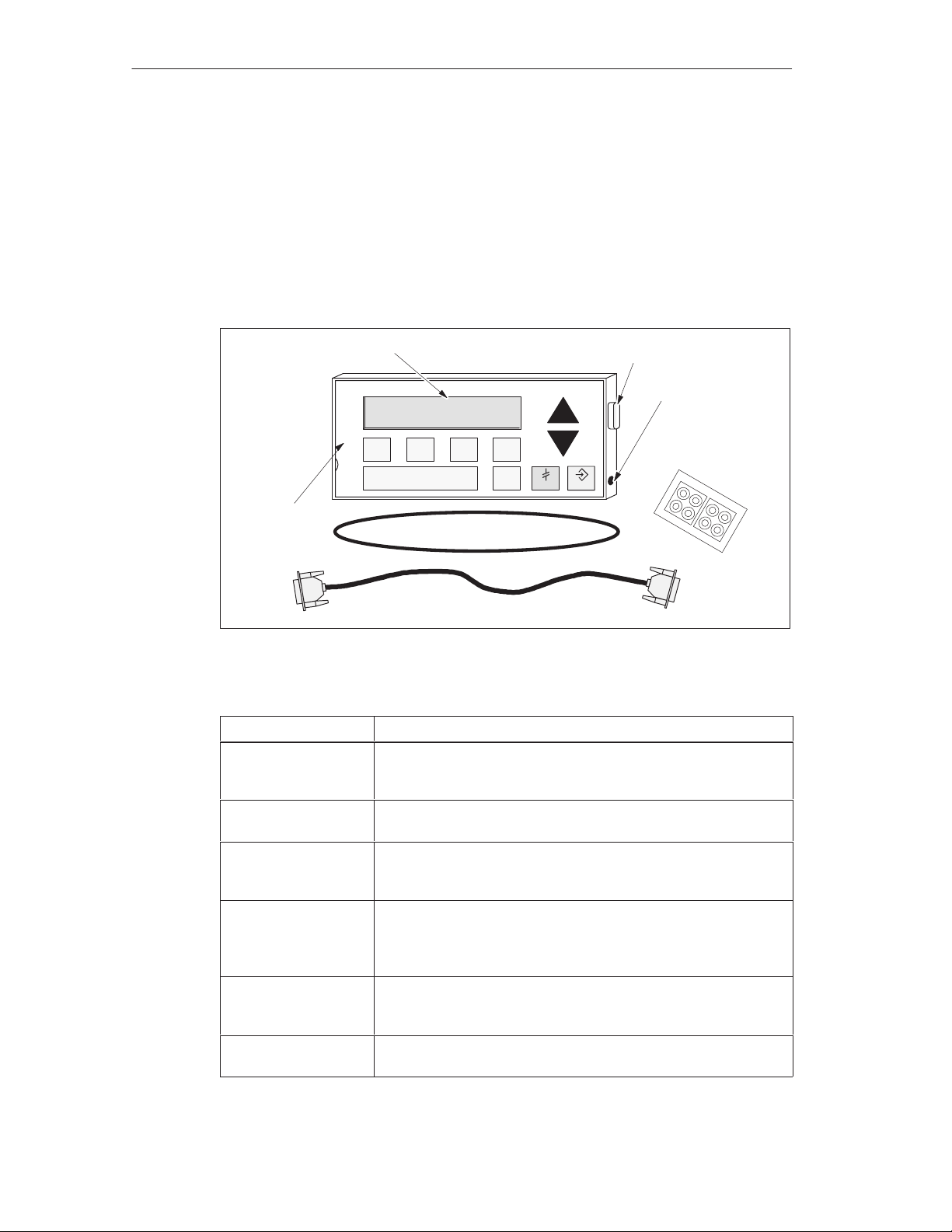
Components of the TD 200
The TD 200 is a small, compact device that provides all the necessary
components for interfacing with your S7-200 CPU. Figure 1-1 shows the major
components of the TD 200. These components are described in Table 1-1. For
further information on the technical specifications of the TD 200, see Appendix A.
Text Display Area
SIEMENS TD 200
Communication
Port
Power
Connection
Spacers
User Label
Gasket
TD/CPU Cable
Figure 1-1 Major Components of the TD 200
Table 1-1 Components of the TD 200
Component
Description
Text Display Area The text display area is a backlit liquid crystal display (LCD) with
two 20-character lines. It allows you to see messages received
from the S7-200 CPU.
Gasket A gasket is provided with the TD 200 for installation in inclement
environments.
Communication Port The communication port is a 9-pin D-connector that allows you to
connect the TD 200 to an S7-200 CPU using the supplied
TD/CPU cable.
Power Connection Y ou can connect an external power supply to the TD 200 through
the power connection access located on the right side of the
TD 200. This connection is not required when you use the
TD/CPU cable.
TD/CPU Cable The TD/CPU cable provides communication and power to your
TD 200. It is a 9-pin, straight-through cable that is supplied with
your TD 200.
User Label The user label is a pull-out label that you can use to customize
the function key labels for your applications.
1-2
SIMA TIC TD 200 Operator Interface
C79000-G7076-C205-05
Page 11

Table 1-1 Components of the TD 200
Component Description
Keys The TD 200 has nine keys. Five of these keys provide
Spacers Self-adhesive spacers are included for mounting the TD 200 to a
TD 200 Keyboard Features
The TD 200 keyboard has a total of nine keys. Table 1-2 describes the five
predefined, context-sensitive command keys.
Table 1-2 Description of Command Keys
Product Overview and Installation
predefined, context-sensitive functions, and four keys provide
user-defined functions.
mounting surface. See Figure 1-4.
Command
Keys
ENTER Use this key to write new data and to acknowledge a message(s).
ESC Use this key to toggle between Display Message mode and Menu mode
or to abort an edit.
UP ARROW The UP arrow increments data and scrolls the cursor to the next higher
priority message.
DOWN ARROW The DOWN arrow decrements data and scrolls the cursor to the next
lower priority message.
SHIFT The SHIFT key modulates the value of all of the function keys. See
Table 1-3 for examples. A flashing “S” is displayed in the lower right of
the TD 200 display when you press the SHIFT key.
Description
Table 1-3 describes the four user-defined function keys (F1, F2, F3, F4). You
define these four function keys in your S7-200 CPU program. Pressing a function
key sets an M bit. Your program can use this bit to trigger a specific action.
Table 1-3 Description of Function Keys
Function Keys
F1 Function key F1 sets the Mx.0 bit.
If you press the SHIFT key along with, or prior to, pressing the F1 key ,
F1 sets the Mx.4 bit.
F2 Function key F2 sets the Mx.1 bit.
If you press the SHIFT key along with, or prior to, pressing the F2 key ,
F2 sets the Mx.5 bit.
F3 Function key F3 sets the Mx.2 bit.
If you press the SHIFT key along with, or prior to, pressing the F3 key ,
F3 sets the Mx.6 bit.
F4 Function key F4 sets the Mx.3 bit.
If you press the SHIFT key along with, or prior to, pressing the F4 key ,
F4 sets the Mx.7 bit.
Description
SIMA TIC TD 200 Operator Interface
C79000-G7076-C205-05
1-3
Page 12
Product Overview and Installation
1.2 Installing the TD 200
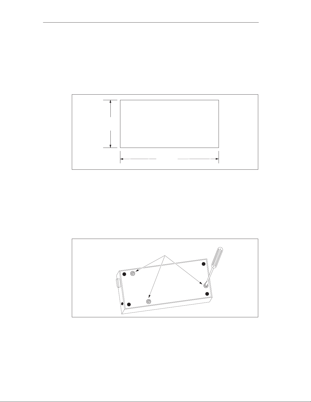
Preparing the Mounting Surface
Use the template in Figure 1-2 to cut a 138 mm x 68 mm or 5.4 in. x 2.7 in. hole in
the mounting surface (DIN 43700).
68 mm
(2.7 in.)
138 mm
(5.4 in.)
Figure 1-2 Mounting Surface Hole Dimensions
Preparing the TD 200 for Mounting
Use the following steps to prepare the TD 200 for mounting.
1. Remove the three screws from the rear of the TD 200 using a flat-head
screwdriver. See Figure 1-3.
2. Remove the backplate of the TD 200.
Mounting
Screws
1-4
Figure 1-3 Removing the Three Mounting Screws
SIMA TIC TD 200 Operator Interface
C79000-G7076-C205-05
Page 13
Product Overview and Installation
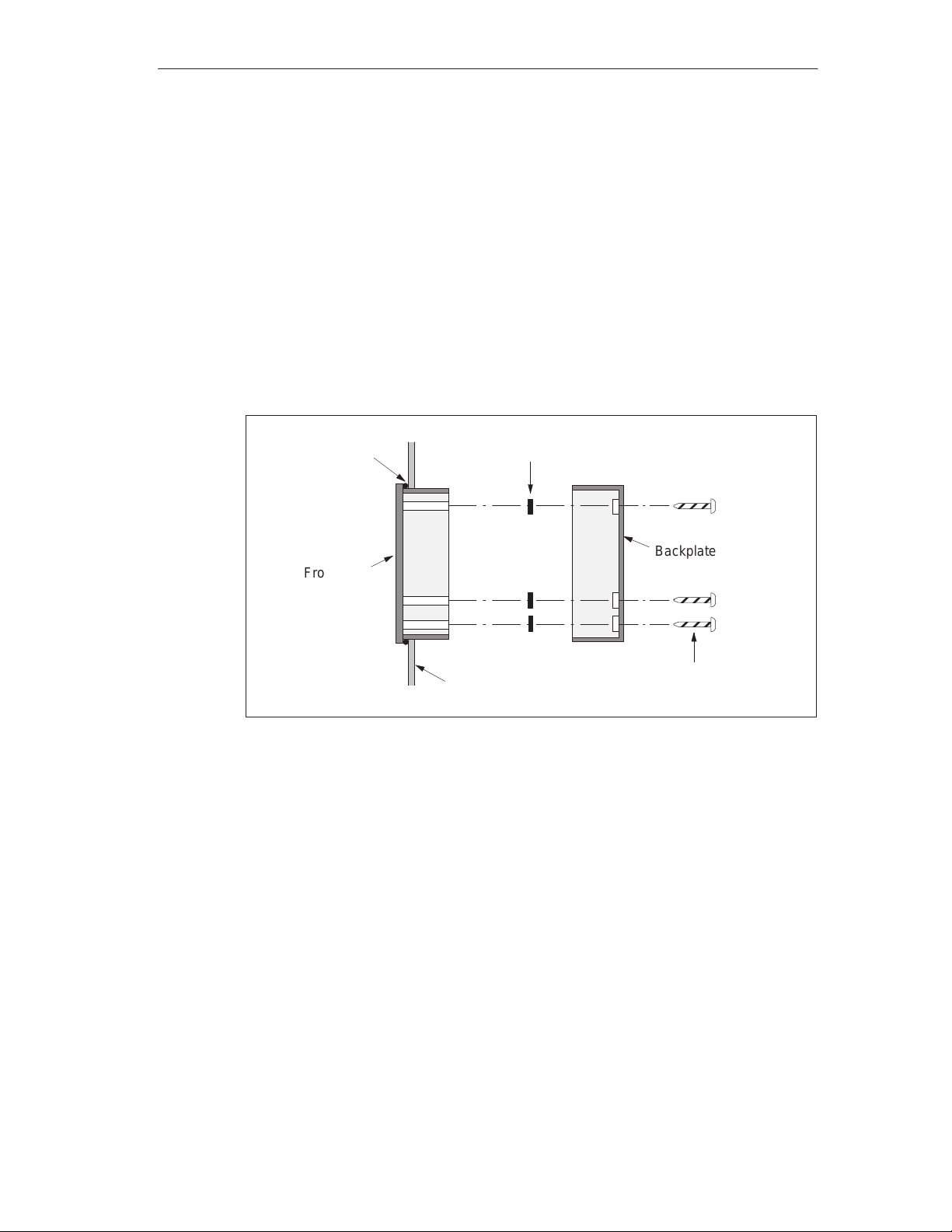
Self-adhesive spacers are included with the TD 200 for mounting the TD 200 to a
mounting surface. The number of spacers you require depends on the thickness of
the mounting surface. Use the following steps to install the spacers.
1. Use the following guidelines to determine the number of spacers required for
proper mounting.
– One spacer for door thickness from 0.3 mm to 1.5 mm (0.01 in. to 0.06 in.)
– Two spacers on top of each other for door thickness of 1.5 mm to 4.0 mm
(0.06 in. to 0.16 in.)
2. Place the spacers over the screw holes on the inside of the backplate. The
spacers maintain pressure on the TD 200 circuit board when the TD 200 is
reassembled. See Figure 1-4.
Figure 1-4 Positioning Spacers
Mounting the TD 200
Use the following steps and refer to Figure 1-4 to complete the mounting of your
TD 200.
1. Place the supplied gasket on the frontplate of the TD 200.
2. Fit the frontplate into the cutout you made in the mounting surface.
Gasket
Frontplate
Spacers
Cabinet Door
or Control Panel
Backplate
Mounting
Screws
3. Secure the backplate onto the frontplate of the TD 200 using the screws you
removed from the backplate. Tighten the screws.
SIMA TIC TD 200 Operator Interface
C79000-G7076-C205-05
1-5
Page 14
Product Overview and Installation
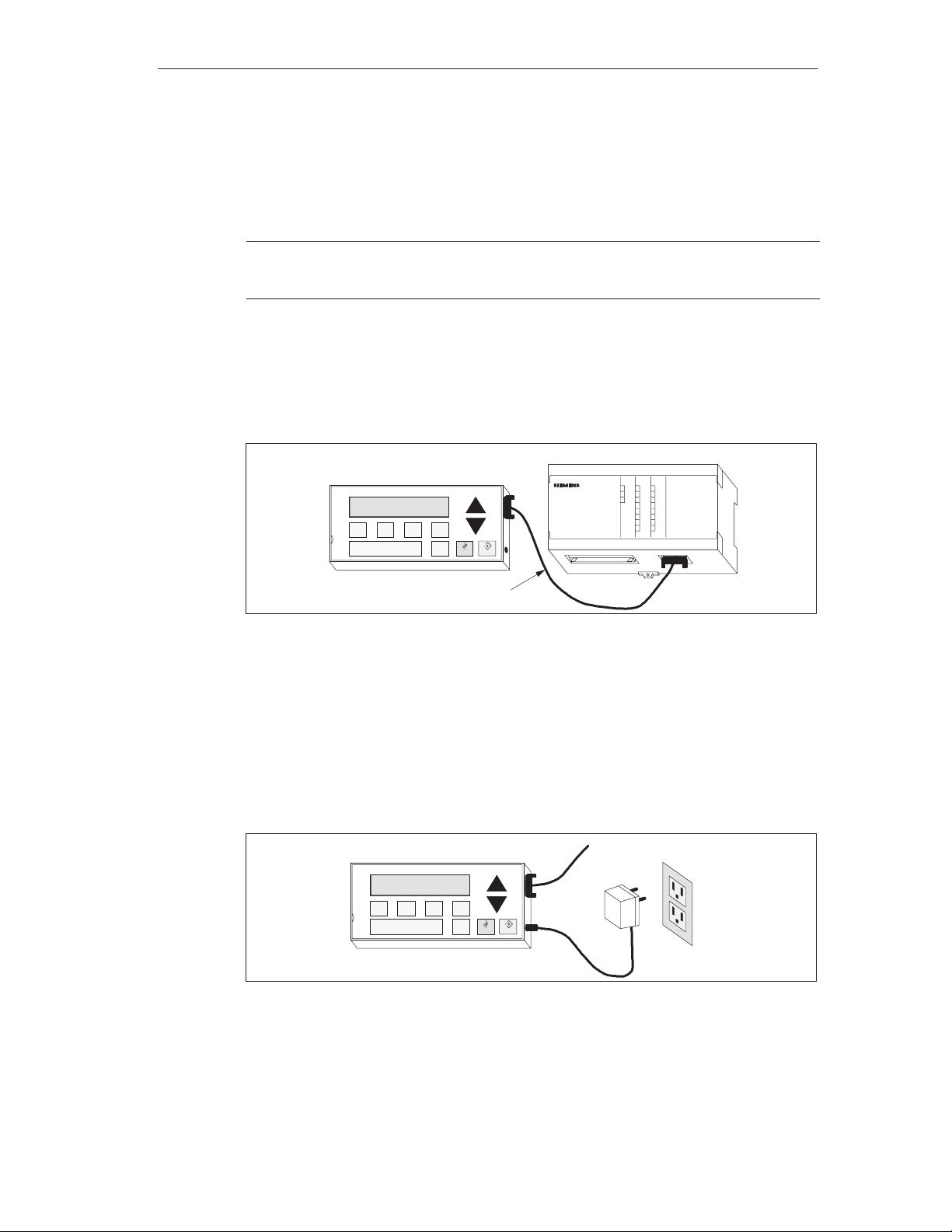
1.3 Connecting the Communication Cable
The TD 200 communicates to the S7-200 CPU through the TD/CPU cable. You
can configure the TD 200 using the TD/CPU cable in the following ways:
One-to-one configuration
Multiple S7-200 CPU configuration
Installing Cable for One-to-One Communication
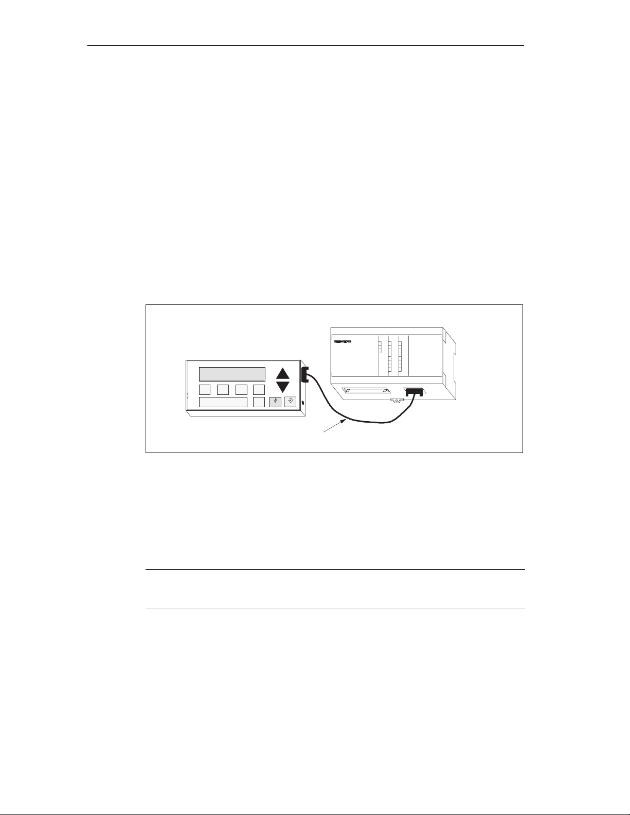
Use a one-to-one network configuration when you have just one S7-200 CPU to
connect to one TD 200. A one-to-one configuration consists of a TD 200, an
S7-200 CPU, and a TD/CPU cable that is supplied with the TD 200.
Figure 1-5 shows you a one-to-one configuration. The TD 200 communicates to
and is powered by the S7-200 CPU using the TD/CPU cable.
S7-200 CPU
TD 200
SIEMENS TD 200
Figure 1-5 One-to-One Configuration
Installing a Multiple CPU Network
Use a multiple CPU network configuration when you have several S7-200 CPUs to
connect to one or more TD 200s. For more information on configuring for multiple
CPU communication, refer to Appendix B.
Note
The TD 200 defaults to address 1 and attempts to communicate to a CPU at address 2.
See Section 3.8 to change the network address if other addresses are used.
TD/CPU Cable
SIMATIC
S7-200
1-6
SIMA TIC TD 200 Operator Interface
C79000-G7076-C205-05
Page 15
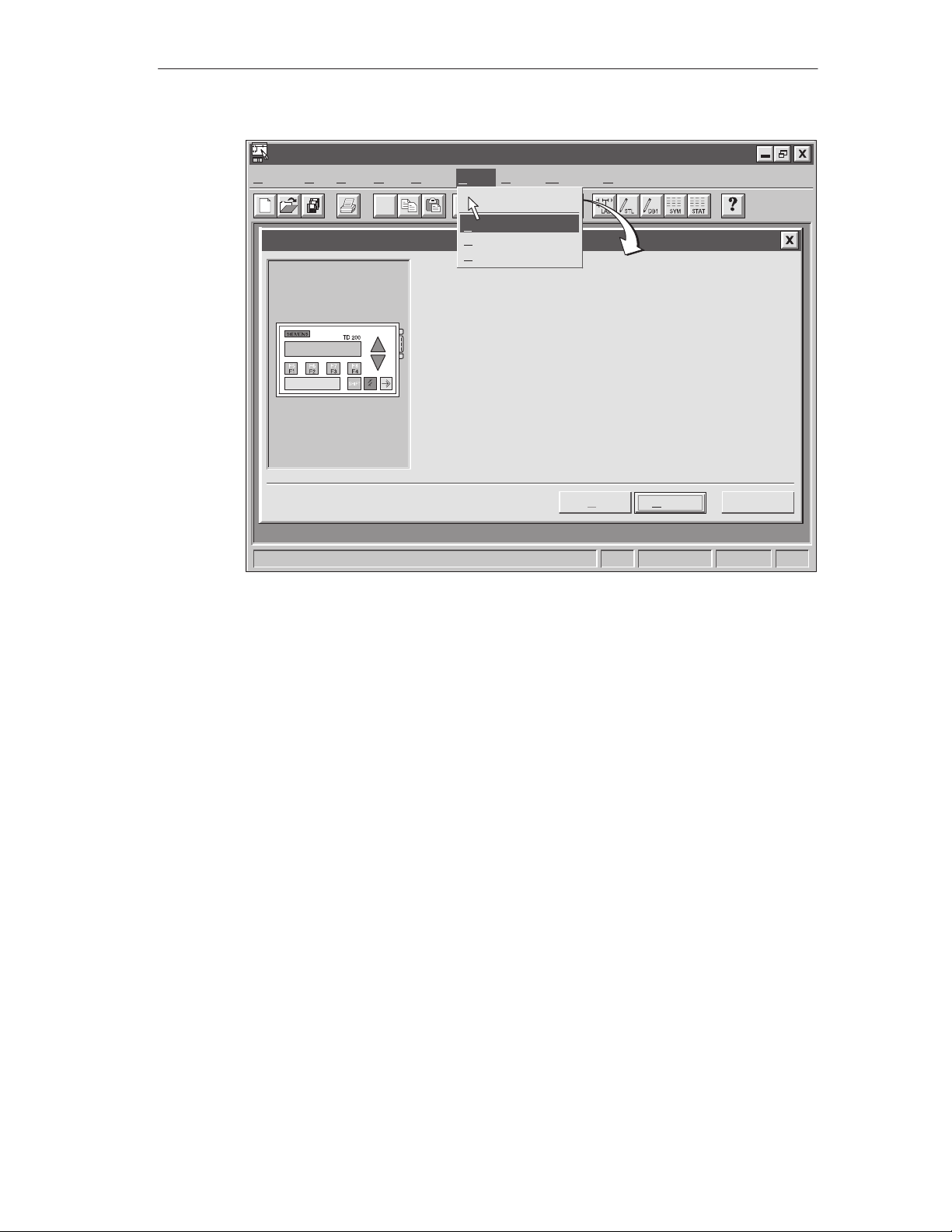
1.4 Connecting a Power Cable
The TD 200 receives power either from the S7-200 CPU or from an external
plug-in power supply unit.
Note
If you are using the TD 200 with a network of S7-200 CPUs, special consideration must be
taken with the communication and power connections. See Appendix B.
Supplying Power from the S7-200 CPU
Figure 1-6 shows you the TD 200 receiving its power from the CPU through the
TD/CPU cable. Use this type of power supply when the distance between the
TD 200 and the S7-200 CPU is less than 2.5 m (8.2 ft.).
TD 200
SIEMENS
TD 200
Product Overview and Installation
S7-200 CPU
TD/CPU Cable
Figure 1-6 Supplying Power with the TD/CPU Cable
Supplying Power from an External Power Supply
Figure 1-7 shows the TD 200 receiving its power from an external power supply.
Use this type of power supply when the distance between the TD 200 and the
S7-200 CPU is greater than 2.5 m (8.2 ft.). If you choose to connect the TD 200 to
the CPU with a longer cable (u2.5 m/8.2 ft.), use PROFIBUS components
(see the SINEC IK10 Catalog). The power supply is available from your Siemens
distributor. See Appendix A for part numbers.
TD 200
SIEMENS
TD 200
SIMATIC
S7-200
To CPU
AC
Figure 1-7 Supplying Power Using an External Power Supply
1.5 Cleaning the Device
To clean the programming device and display, use only o soft cotton cloth and a
neutral cleaning agent.
SIMA TIC TD 200 Operator Interface
C79000-G7076-C205-05
1-7
Page 16

Product Overview and Installation
1-8
SIMA TIC TD 200 Operator Interface
C79000-G7076-C205-05
Page 17

Configuring the TD 200
The TD 200 is a text display device that displays messages enabled by the
S7-200 CPU. You do not have to configure or program the TD 200. The only
operating parameters stored in the TD 200 are the address of the TD 200, the
address of the CPU, the baud rate, and the location of the parameter block. The
configuration of the TD 200 is stored in a TD 200 parameter block located in the
variable memory (V memory) of the CPU. The operating parameters of the
TD 200, such as language, update rate, messages, and message-enabled bits, are
stored in the TD 200 parameter block in the CPU.
Upon power-up, the TD 200 reads the parameter block from the CPU. All of the
parameters are checked for legal values. If everything is acceptable, the TD 200
starts actively polling the message-enabled bits to determine what message to
display, reads the message from the CPU, and then displays the message.
Chapter Overview
Section Description Page
2.1 Starting the STEP 7-Micro/WIN TD 200 Configuration Wizard 2-2
2.2 Creating a Sample Program 2-20
2
SIMA TIC TD 200 Operator Interface
C79000-G7076-C205-05
2-1
Page 18

Configuring the TD 200
2.1 Starting the STEP 7-Micro/WIN TD 200 Configuration Wizard
STEP 7-Micro/WIN provides a “wizard” that makes it easy to configure the
parameter block and the messages in the data memory area of the S7-200 CPU.
The TD 200 Configuration Wizard automatically writes the parameter block and
message texts to the data block editor after you finish choosing the options and
creating the messages. This data block can then be downloaded to the CPU. For
detailed information about the TD 200 parameter block and message formats, see
Appendix D.
This chapter contains the procedure for creating a sample TD 200 application. Use
the instructions in this example to create a TD 200 parameter block and three
messages using the TD 200 Configuration Wizard. The first message is text only.
The second message contains both text and embedded data. The third message is
a text message that requires acknowledgement by the operator.
The example also shows how to use the function keys to enable a message and
how to use the acknowledge- and edit-notification bits within your program.
To open the wizard, select the menu command Tools > TD 200 Wizard... as
shown in Figure 2-1.
To navigate through the dialog boxes of the wizard, click on “Next>.” At any time
during the procedure, click on the “<Prev” button to go back to a previous dialog
box if you need to change or review any of the parameters you have defined. In
the final dialog box, click on “Finish” to validate and save the parameter block and
close the wizard.
You can view the configured parameter block and messages by opening the
STEP 7-Micro/WIN data block editor.
2-2
SIMA TIC TD 200 Operator Interface
C79000-G7076-C205-05
Page 19
STEP 7-Micro/WIN - c:\microwin\project1.prj
Project Edit View CPU Debug Tools Setup Window Help
"
TD 200 Configuration Wizard
Tools
Instruction Wizard..
TD 200 Wizard...
Project Services ...
Edit/Add T ools...
This wizard will help you configure TD 200 messages quickly and
easily . When you are finished, the wizard will generate the supporting
data block code for you.
T o begin configuring TD 200 messages, click Next.
Configuring the TD 200
< Prev
Figure 2-1 Accessing the TD 200 Configuration Wizard
CancelNext >
1, 1
SIMA TIC TD 200 Operator Interface
C79000-G7076-C205-05
2-3
Page 20
Configuring the TD 200
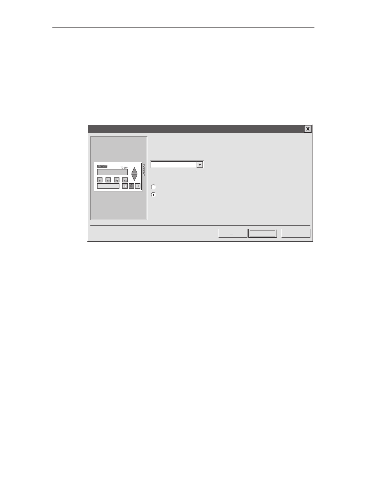
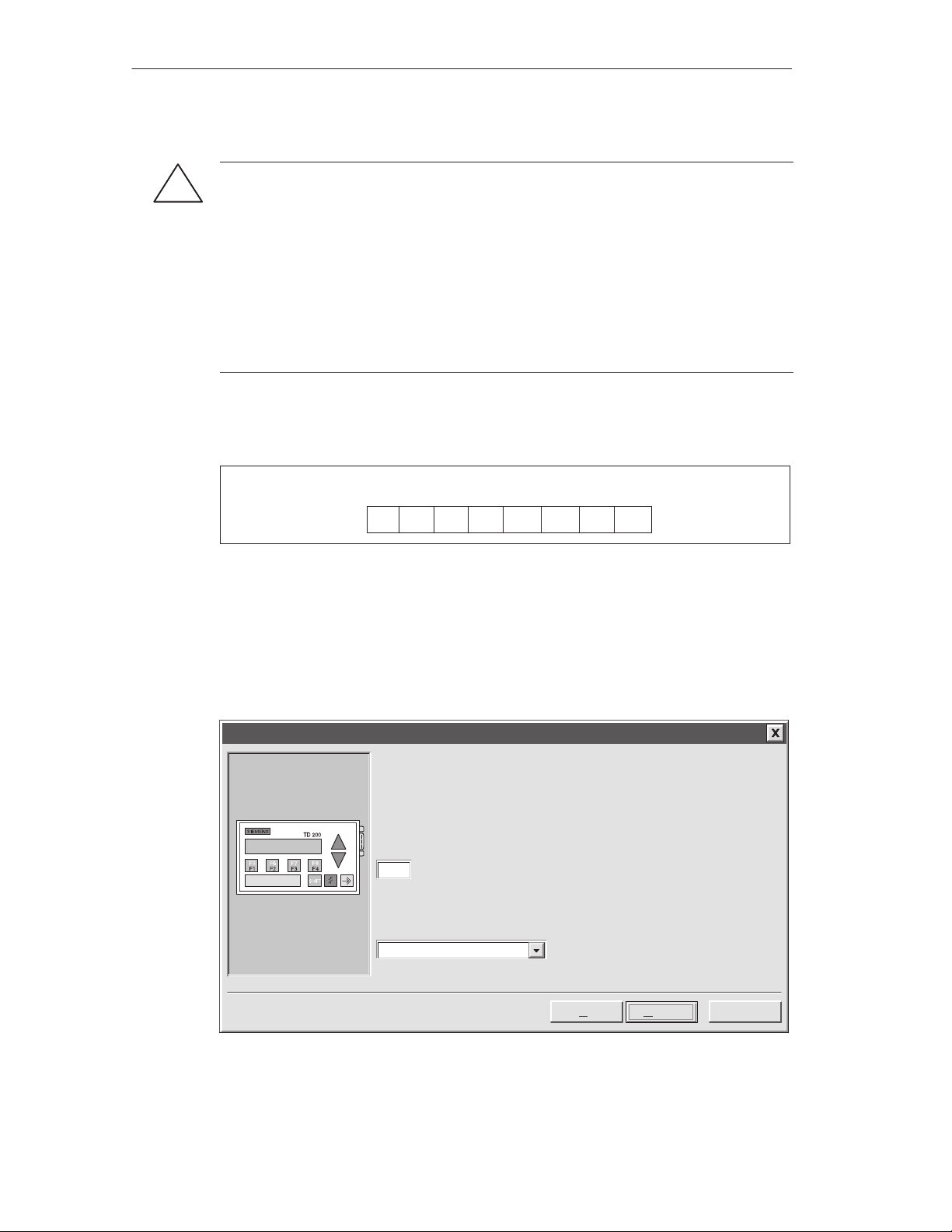
Selecting Language and Bar Graph Character Set
The first dialog box in the TD 200 Configuration Wizard allows you to select the
language and character set. Use the drop-down list box shown in Figure 2-2 to
select the language in which the TD 200 menus display. (This selection does not
affect the text of the user messages displayed on the TD 200.) Use the option
buttons to select the standard character set or the alternate character set. The
alternate character set allows you to display bar graph charts on the TD 200.
TD 200 Configuration Wizard
Y ou can configure the TD 200 to display menus and prompts in a specific
national language.
Which national language would you like your TD 200 to support?
English
Would you like to enable the Bar Graph character set?
Yes
No
Figure 2-2 Wizard: Language and Character Set
< Prev
Next >
Cancel
2-4
SIMA TIC TD 200 Operator Interface
C79000-G7076-C205-05
Page 21
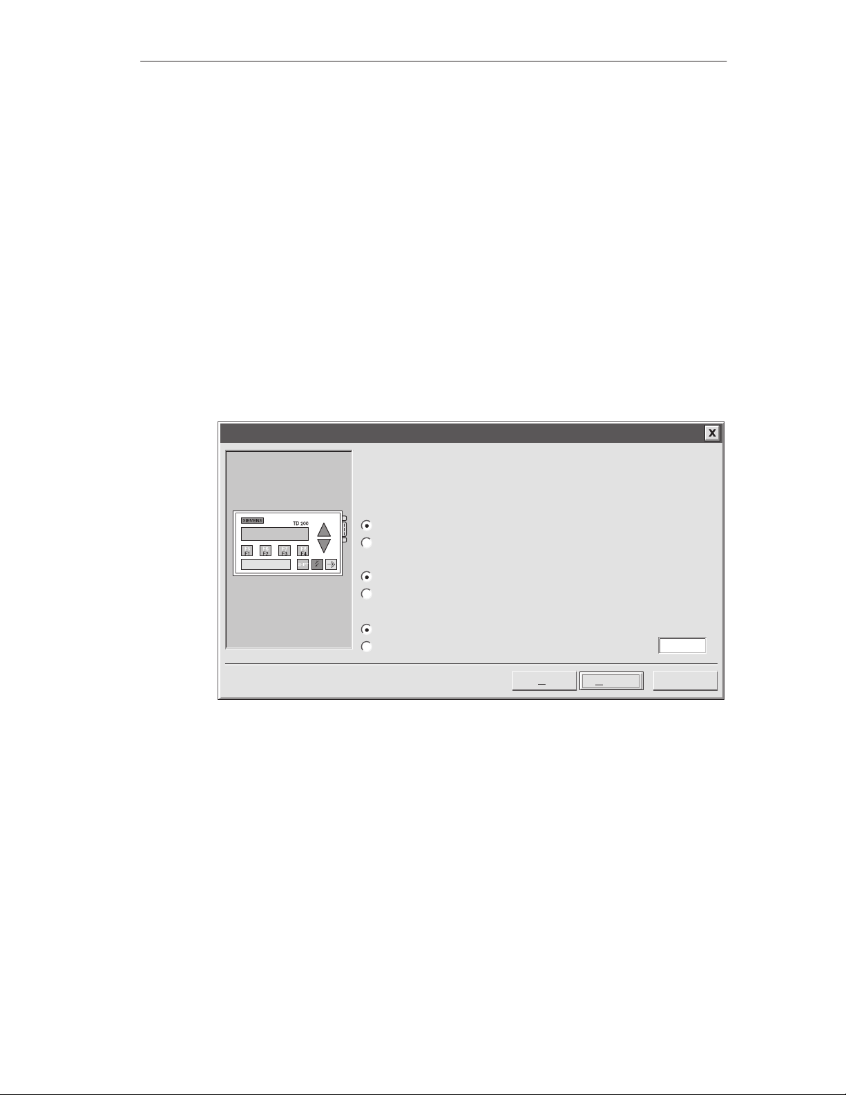
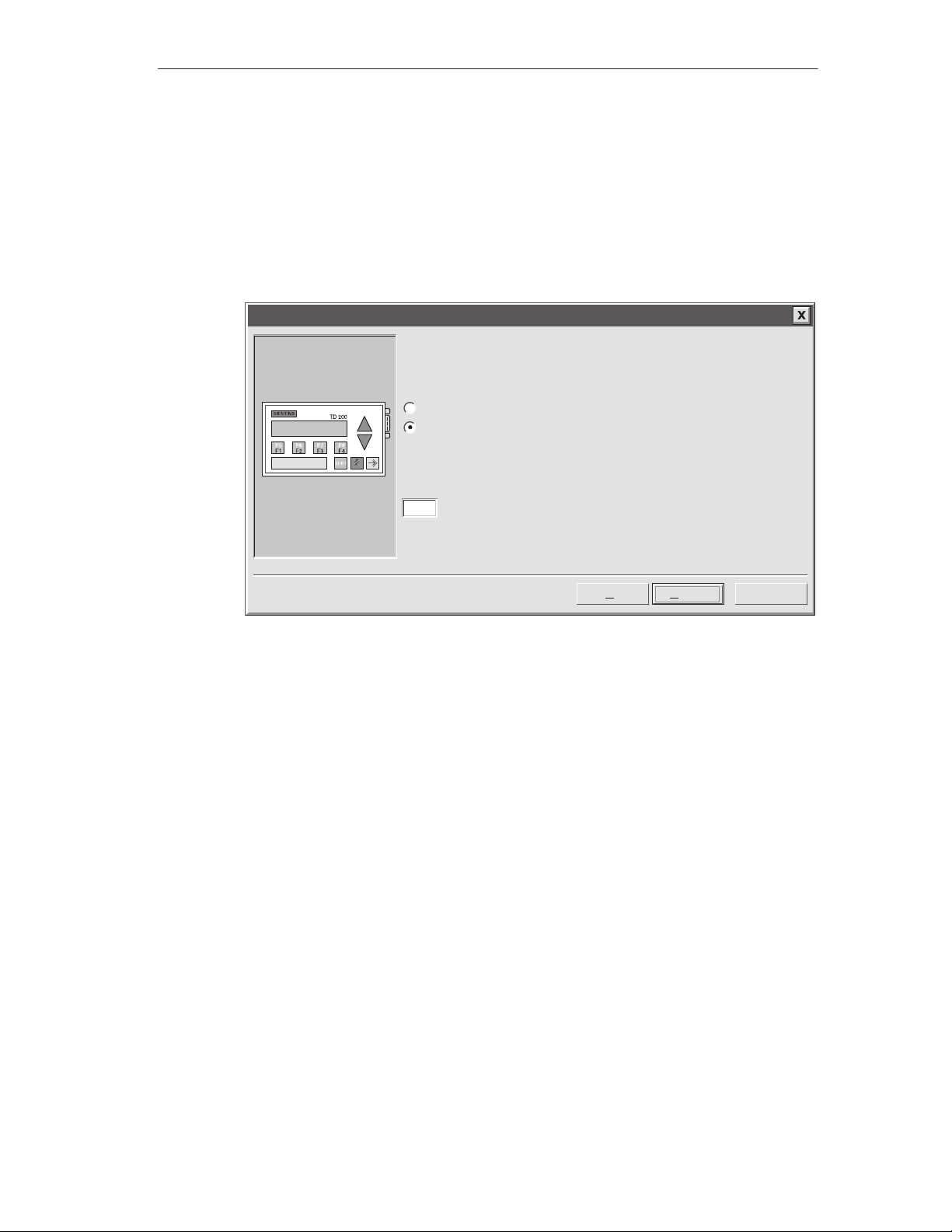
Enabling Time-of-Day, Force Function, and Password Protection
The dialog box shown in Figure 2-3 allows you to enable Menu mode options and
set an edit password.
The Time-of-Day (TOD) and force menu selections allow you to selectively enable
the TOD Clock menu and/or the Force menu. Once a selection is enabled, you are
allowed to access that menu in the TD 200. If the menu is not enabled, it does not
appear in the TD 200 Menu mode.
The password protection selection allows you to enable a four-digit password (from
0000 to 9999). The password controls the ability of the operator to edit variables
embedded in a message and to access the Menu mode. If you enable password
protection, a field appears in the dialog box for you to set the password. This
password is not the CPU password and it is stored in the TD 200 parameter block.
For this example, use the option buttons to select the modes shown in Figure 2-3.
Set 1111 as your password.
TD 200 Configuration Wizard
Configuring the TD 200
You can configure your TD 200 to allow the user to set the Time of Day clock in the
CPU, and to Force I/O in the CPU. You can also passwordĆprotect these options, so
that a user may only access them after entering the correct 4Ćdigit password.
Would you like to enable the Time-of-Day (T OD) menu on your TD 200?
Yes
No
Would you like to enable the force menu on your TD 200?
Yes
No
Would you like to enable password protection?
Yes
No
< Prev
Figure 2-3 Wizard: Time-of-Day Clock, Force I/O, and Password Protection
Specifying Function Key Memory Bits and Display Update Rate
The dialog box shown in Figure 2-5 allows you to specify the marker byte
(M memory) address for the TD 200 function keys and determine the update rate
of the TD 200.
You must reserve eight bits of marker memory (M bits) for the TD 200 to use when
a function key is pressed. Your program can inspect these bits and take an action
when a key is pressed. One M bit is set by the TD 200 each time the
corresponding function key is pressed. Always reserve an M Area address even
when your program does not utilize function keys. Valid address values for specific
CPUs are defined in the
Manual
.
SIMATIC S7-200 Programmable Controller System
Next >
1111Password (0000 - 9999):
Cancel
SIMA TIC TD 200 Operator Interface
C79000-G7076-C205-05
2-5
Page 22
Configuring the TD 200
Warning
!
The TD 200 sets an M bit each time a function key is pressed. If you do not intend to use
function keys, and so do not assign an M byte address for function keys, the TD 200
defaults to byte M0 for the function keys. If your program uses bits in M0, and a user
presses any function key, the TD 200 sets the corresponding bit in M0, overwriting the
value assigned to that bit by your program.
Inadvertent changes to M bits could cause your program to behave unexpectedly .
Unpredictable controller operation could cause death or serious injury to personnel, and/or
damage to equipment.
Always reserve an M area address, even when your program does not utilize function
keys.
Figure 2-4 shows a referenced byte (MBn) and shows which bit of the byte is set
by each function key.
MSB
7
ShiftF4ShiftF3ShiftF2Shift
MBn
6543 21
F4 F3 F2 F1
F1
LSB
0
Figure 2-4 Bits Set by Each Function Key
The update rate selection determines how often the TD 200 polls the S7-200 CPU
for messages to display. The actual update time may be slower than the time that
you select because of the size of the message, the processing required, or
network traffic.
For this example, select M0 and As fast as possible as shown in Figure 2-5.
TD 200 Configuration Wizard
The TD 200 has 8 function keys (F1 through F4 and SHIFT F1 through SHIFT F4)
that are used to set memory bits in the CPU. You must reserve eight bits of memory
(M bits) for the TD 200 to set when a function key is pressed. One M bit is set by
the TD 200 each time the corresponding function key is pressed.
Which byte of M memory would you like to reserve for the TD 200?
0
The update rate determines how often the TD 200 polls the CPU for messages to
display. How often would you like the TD 200 to poll for messages?
2-6
As fast as possible
< Prev
Figure 2-5 Wizard: Function Key Memory Bits and Update Rate
SIMA TIC TD 200 Operator Interface
Next >
C79000-G7076-C205-05
Cancel
Page 23
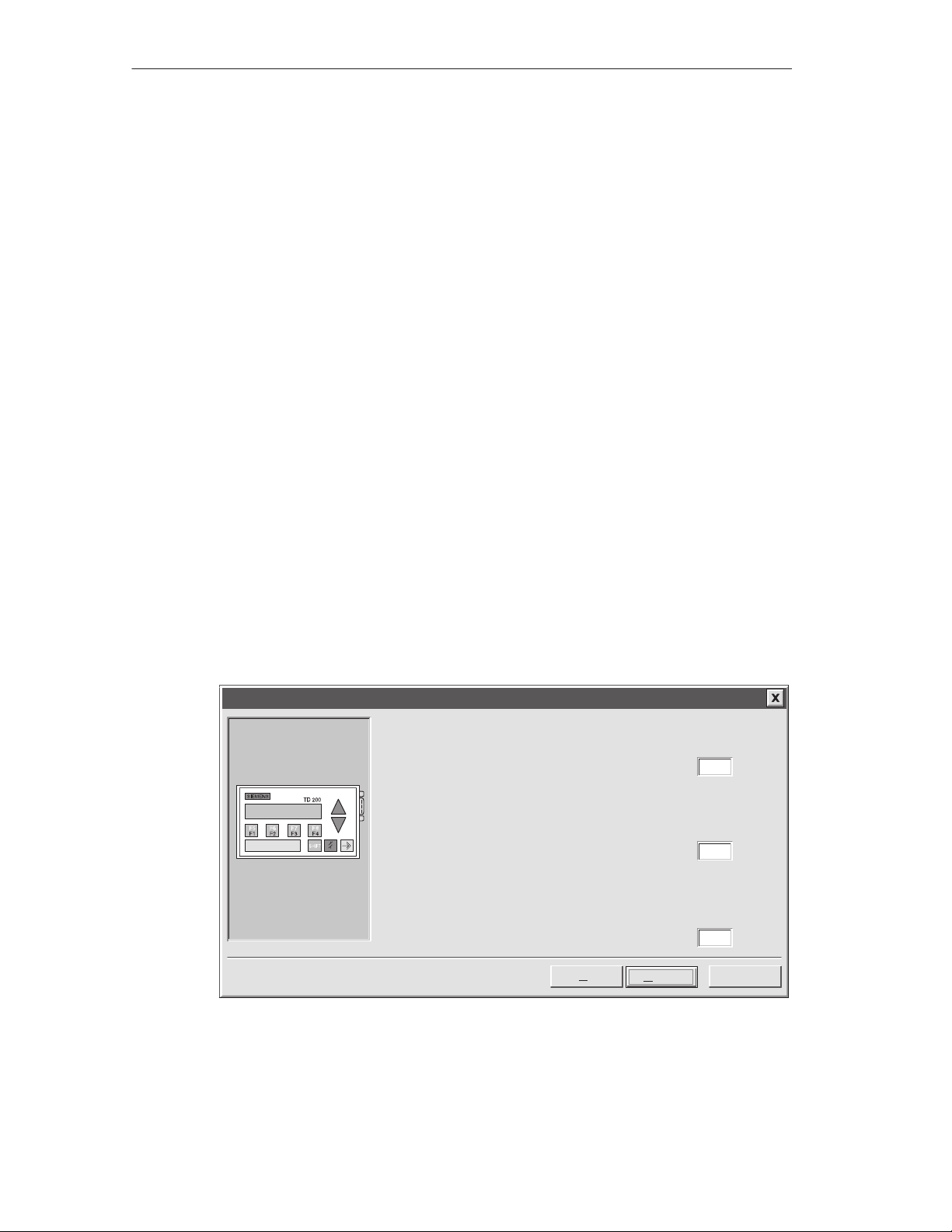
Selecting Message Size and Number of Messages
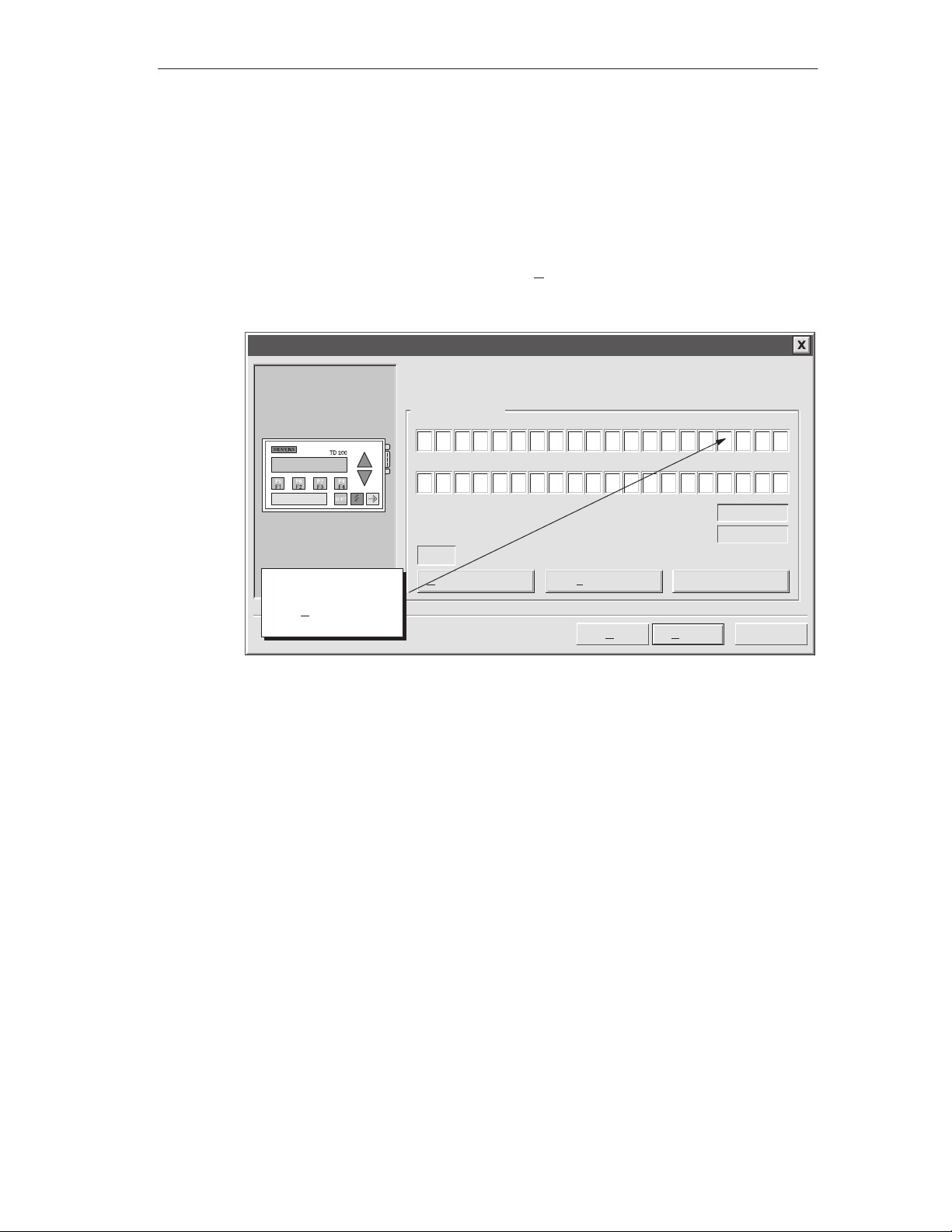
The dialog box shown in Figure 2-6 allows you to set the message size and
quantity of messages. Select a 20- or 40-character size for your messages. The
TD 200 supports up to 80 messages. Enter a number from 1 to 80 in the text field
to specify the number of messages you want to create.
For this example, choose three 40-character messages.
TD 200 Configuration Wizard
The TD 200 allows two message sizes, please select the message size
you wish to support.
20 character message mode - displays two messages at a time
40 character message mode - displays one message at a time
The TD 200 allows you to configure up to 80 messages. How many
messages do you wish to configure?
3
Configuring the TD 200
< Prev
Figure 2-6 Wizard: Message Size and Number of Messages
Next >
Cancel
SIMA TIC TD 200 Operator Interface
C79000-G7076-C205-05
2-7
Page 24
Configuring the TD 200
Specifying Parameter Block Address, Message Enable Address, and Message Location
The dialog box shown in Figure 2-7 allows you to specify starting addresses for the
parameter block, the message enable flags, and the messages.
The TD 200 looks for a parameter block in the V memory of the CPU. The default
location for the parameter block is VB0. The default location can be changed. See
Section 3.8 and Section D.1 for information about placing the parameter block at
other locations.
The starting byte for the message enable flags defines the location in V memory at
which the message enable flags begin. There are eight message enable flags
stored in each byte. Whole bytes must be allocated for message enable flags even
if all the bits are not used. The text in the dialog box shown in Figure 2-7 specifies
how many bytes of V memory are needed for message enable flags based on the
number of messages you set in the previous (Figure 2-6) dialog box.
The starting byte for message information defines the starting location of the first
message in V memory. Messages are placed consecutively in memory. Either 20
or 40 bytes are reserved for each message based on your selection in the previous
dialog box (Figure 2-6). The text in the dialog box shown in Figure 2-7 specifies
how many bytes are required for messages.
Values for the parameter block, enable flags, and message information starting
addresses are CPU specific. See the
System Manual
for the valid address ranges for specific CPUs.
SIMATIC S7-200 Programmable Controller
For this example, set the parameter block starting byte to 0, the enable flags
address to 12, and the message information starting address to 40 as shown in
Figure 2-7.
TD 200 Configuration Wizard
Y ou must now define where you would like the 12 byte parameter definition
to reside in your data block. It is usually located at VB0.
0Starting byte for 12 byte parameter block:
Y ou have defined 3 messages requiring 1 consecutive bytes for message
enable flags. Y ou must now define where you would like the enable flags to
reside in your data block.
12Starting byte for enable flags:
Y ou have defined 3 messages requiring 120 consecutive bytes for the
message information. You must now define where you would like the
message information to reside in your data block.
40Starting byte for message information:
< Prev
Next >
Cancel
2-8
Figure 2-7 Wizard: Block Address, Enable Flags, and Message Location
SIMA TIC TD 200 Operator Interface
C79000-G7076-C205-05
Page 25
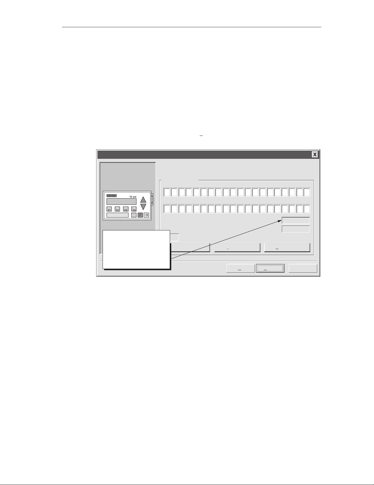
Creating A Text-Only Message
The dialog box in Figure 2-8 allows you to enter the text for a TD 200 message.
The dialog box also shows you the starting address of the message (Message
beginning address). It also shows you the address of the message-enabled bit for
this message. Your program uses this message-enabled bit to control the display
of this message on the TD 200. Setting the message-enabled bit to a 1 causes the
TD 200 to read and display this message.
For this example, type in your message as shown in Figure 2-8. This is a text-only
message, so there is no embedded data. Since there are two more messages to
configure in this example, click on “Next Message >” to continue.
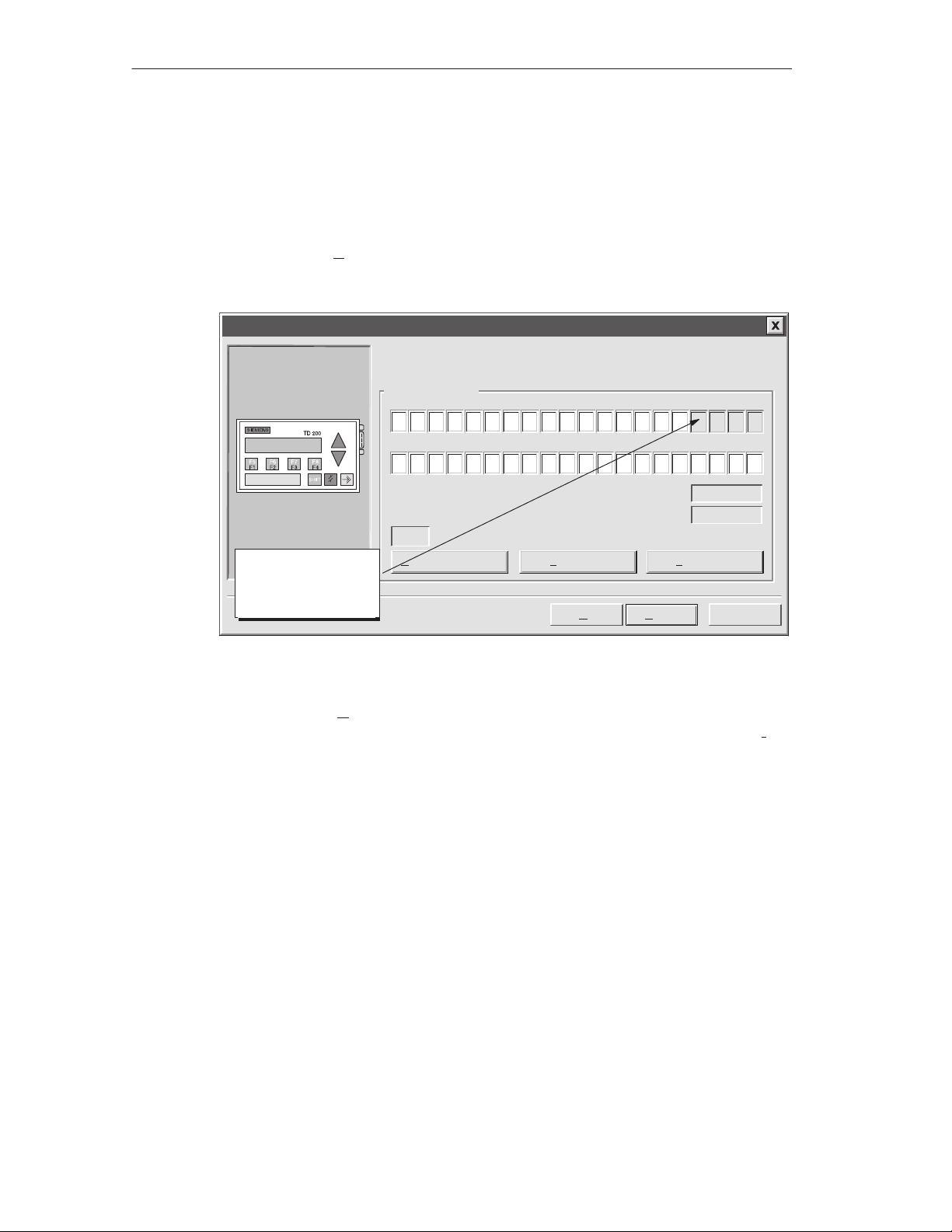
TD 200 Configuration Wizard
Configuring the TD 200
Y ou have asked to configure 3 message(s). Define your message by
placing your highest priority message first.
Message 1 of 3
PRESS F1 TO DI SPLAY
THE NEXT MESSAGE . . .
5
25
10 15 20
30 35 40
Note: This field shows the
address of the particular
message. VB40 is the
address of MSG1, VB80
would be displayed for
MSG2, and so on.
INS
Embedded Data...
Figure 2-8 Wizard: 40-Character Message
Message beginning address:
Message enabled bit:
<Previous Message Next Message >
< Prev
Finish
VB40
V12.7
Cancel
SIMA TIC TD 200 Operator Interface
C79000-G7076-C205-05
2-9
Page 26

Configuring the TD 200
Embedding Data Values in a Text Message
You can place a data value within the message that displays on the TD 200. In
order to display a data value, you must reserve space in the message for the data
value and for format information. The format information tells the TD 200 how to
display and edit the data value. The format information requires the space of two
characters in your message. Word data values require the space of two characters
in addition to the format information (four characters total). Double word or real
(floating point) values require the space of four characters in addition to the format
information (six characters total).
When you insert a data value into a message, you must be sure there are enough
characters to contain the format information and the embedded data value on the
current line of the display. For example, if you insert a word value, (two characters
for the word value and two characters for the format information), you must allow
at least four spaces between the starting position of the embedded data value and
the end of the current message line.
The right-most character of an embedded data value serves as the anchor point
for that value in the TD 200 display. Data values are always right justified to that
anchor point within messages on the TD 200 display. As a data value grows in
magnitude, it utilizes more spaces to the left of the anchor point and can begin to
use the spaces occupied by the message text. Be sure to leave sufficient space
between the end of your text and the anchor point to allow for the expected range
of the data value.
The number of display characters used to display a value varies with the size of
the value. This number of characters required to display a number is not the same
as the number of characters used to store the embedded data value in the
message. The number of display characters required depends on the range of
values for that number in a specific application. See Table D-1 for examples of the
number of display characters required for different display formats.
The TD 200 displays all values as decimal numbers. Positive signed values are
displayed without a sign. Negative signed values are displayed with a leading
minus sign. Unsigned values are displayed without a sign. A leading zero is used
for all fractional numbers (for example, 0.5). Real numbers are displayed with the
number of decimal places you specify. The value is rounded to the specified
decimal place.
2-10
SIMA TIC TD 200 Operator Interface
C79000-G7076-C205-05
Page 27
Configuring the TD 200
For this example, type in the text shown in Figure 2-9. This example message has
two embedded data values, one in the top line and one in the second line. The
data value in the top line is an integer. The data value in the second line is a real
number.
A word value requires two characters for the value plus two more characters for
format information. Place the cursor at the character position shown in Figure 2-9
(four spaces from the right). Click on the “Embedded Data...” button to bring up the
Embedded Data dialog box.
TD 200 Configuration Wizard
Y ou have asked to configure 3 message(s). Define your message by
placing your highest priority message first.
Message 2 of 3
PREV. SETPOINT :
NEW SETPOI NT :
5
25
10 15 20
30 35 40
Message beginning address:
Message enabled bit:
INS
Place cursor at the
correct position and
click “Embedded
Data...”
Embedded Data...
<Previous Message Next Message >
< Prev
Figure 2-9 Wizard: Embedding Variable Data Value in a Message
Finish
VB80
V12.6
Cancel
SIMA TIC TD 200 Operator Interface
C79000-G7076-C205-05
2-11
Page 28

Configuring the TD 200
Formatting the Embedded Data Value
Figure 2-10 shows the Embedded Data dialog box. This dialog box allows you to
specify the data type, format, and display characteristics of an embedded data
value. You can also select whether or not the message requires acknowledgement,
whether the data value can be edited, and whether or not editing requires a
password. Some options depend on the selections you make and do not appear
when the dialog box opens.
The data format selection defines the size of the data value embedded in the
message:
Select “None” when a message requires acknowledgement but there is no
embedded data value to be displayed on the TD 200.
Select “Word“ when the embedded data value is an integer. A word or integer
value requires the space of two characters within your message to hold the
data value.
Select “Double Word” when the embedded data value is a double word or a real
(floating point) value. A double word or real value requires the space of four
characters within your message to hold the data value.
The display format selection tells the TD 200 whether the data value is signed or
unsigned. The TD 200 uses this information when editing the data value. Signed
values may be either positive or negative numbers. Unsigned values are restricted
to positive numbers.
The selection for digits to the right of the decimal provides scaling for the display of
the data value. If the data value is an integer, this selection allows you to scale the
integer value for display by specifying the location of the decimal point. For
example, if the data value is equal to 123 and you select 1 digit to the right of the
decimal, the TD 200 displays 12.3.
The Embedded Data dialog box contains a check box to require acknowledgement
of the message. If a message requires acknowledgement, it flashes on the TD 200
display until the operator presses ENTER. The dialog box also contains a check
box for allowing editing of the data value. If this box is selected, the operator can
edit the embedded data value. If the box is not checked, the data cannot be edited.
The Embedded Data dialog box also lists the address of the data value within the
message. The user program uses this address to write the data value in the
message.
For this example, make the selections shown in Figure 2-10 and click “OK.”
2-12
SIMA TIC TD 200 Operator Interface
C79000-G7076-C205-05
Page 29
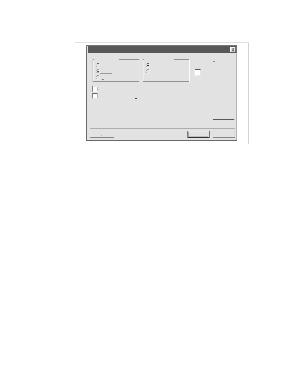
Embedded Data
Configuring the TD 200
Data Format: Display Format:
None
Word
Double Word
User must acknowledge message
Is the user allowed to edit this data?
Delete
Signed
Unsigned
Figure 2-10 TD 200 Message: Creating a Word Embedded Data
Digits to the right of the
decimal
1
VW98Address of Data Value:
OK
Cancel
SIMA TIC TD 200 Operator Interface
C79000-G7076-C205-05
2-13
Page 30
Configuring the TD 200
Figure 2-11 shows the message dialog box after you have formatted the first
embedded data value. The grayed fields show the characters used by the format
information (always two) and the data value (two for word values).
The second data value in the message is a real number. Real numbers require four
characters plus two characters for format information. Move the cursor to position
35 and click on “Embedded Data...” to enter the format information for the second
data value.
TD 200 Configuration Wizard
Y ou have asked to configure 3 message(s). Define your message by
placing your highest priority message first.
Message 2 of 3
PREV. SETPOINT :
NEW SETPOI NT :
5
25
10 15 20
30 35 40
Message beginning address:
Message enabled bit:
INS
Note: Grayed fields
are place holders for
embedded data
values.
Figure 2-11 Wizard: Embedded Data Value Place Holder in Message
Embedded Data...
<Previous Message Next Message >
< Prev
Finish
VB80
V12.6
Cancel
This variable displays as a real number which requires a double word data format.
After you select “Double Word,” the Display Format area allows selection of a real
(floating point) number format. For real numbers, the field entitled Digits to the right
of the decimal defines the fixed decimal location of the real number in the TD 200
display. The TD 200 rounds a real number to the specified decimal place. For
example, if the real number value is 123.456 and you select 2 digits to the right of
the decimal, the TD 200 displays this value as 123.46.
In this example, this variable should be editable by the user. Select the check box
that allows the user to edit the data. Once the edit-allowed selection has been
made, two new fields appear in the Embedded Data dialog box.
The Edit Notification Bit field specifies the location of a bit which the TD 200 sets to
1 whenever the data value is edited and written to the CPU. The CPU program
uses the edit-notification bit to recognize when an editable data value has been
changed. The program can then read and make use of the edited value. The user
program is responsible for resetting this bit to 0.
2-14
The password-protected check box asks you if you wish to require a password for
editing this data value. If checked, the operator must enter a password before
being allowed to edit the data value. You selected the password at the beginning of
the configuration process (see Figure 2-3); it is shown in the Password for Edit
field.
SIMA TIC TD 200 Operator Interface
C79000-G7076-C205-05
Page 31

Configuring the TD 200
After you have made the selections shown in Figure 2-12, click “OK” to continue
the configuration for this example.
Embedded Data
Data Format: Display Format:
None
Word
Double Word
User must acknowledge message
Is the user allowed to edit this data?
Should the user edit of data be Password-protected?
Password for Edit:
1111
Delete
Signed
Unsigned
Real (floating point)
Digits to the right of the
decimal
1
Note: These fields
appear only when
certain options are
chosen.
V114.2Edit Notification Bit:
VD1 16Address of Data Value:
OK
Cancel
Figure 2-12 Embedded Data: Making the Data Editable and Password Protected.
Figure 2-13 shows the message dialog box after you have completed your
selections for both embedded data values in this message. Click “Next Message
>” to continue the example.
TD 200 Configuration Wizard
Figure 2-13 Wizard: Completed Second Message
SIMA TIC TD 200 Operator Interface
C79000-G7076-C205-05
Y ou have asked to configure 3 message(s). Define your message by
placing your highest priority message first.
Message 2 of 3
PREV. SETPOINT :
NEW SETPOI NT :
INS
Embedded Data...
5
25
10 15 20
30 35 40
Message beginning address:
Message enabled bit:
<Previous Message Next Message >
< Prev
Finish
VB80
V12.6
Cancel
2-15
Page 32

Configuring the TD 200
Creating a Message That Requires Acknowledgement
To ensure that important messages are displayed and acknowledged by an
operator, you can configure a message to require acknowledgement. This
message flashes when displayed on the TD 200. The operator must press the
ENTER key on the TD 200 to acknowledge the message.
When the message is acknowledged, the following things happen:
The message stops flashing.
The acknowledge-notification bit is set in the CPU.
The message-enabled bit for this message is reset in the CPU.
To force acknowledgement of a message, embed a format word in the message.
The format word tells the TD 200 how to display the message. The format word
uses two contiguous characters within your message. Since there is no data
associated with this format word, the format word can be placed anywhere in your
message (not just at the end). The format characters appear as blank spaces on
the TD 200 display.
For this example, enter the message text as shown in Figure 2-14. Place the
cursor on the 39th digit position and click on “Embedded Data...” button below.
TD 200 Configuration Wizard
Y ou have asked to configure 3 message(s). Define your message by
placing your highest priority message first.
Place cursor on the
39th position and click
“Embedded Data...”
Message 3 of 3
ACKNOWLEDGE MESSAGE
BY PRESS ING ENTER . . .
INS
Embedded Data...
5
25
10 15 20
30 35 40
Message beginning address:
Message enabled bit:
<Previous Message Next Message >
< Prev
Figure 2-14 Wizard: Embedding Data to Require Acknowledgement
Finish
VB120
V12.5
Cancel
2-16
SIMA TIC TD 200 Operator Interface
C79000-G7076-C205-05
Page 33

Configuring the TD 200
The Embedded Data dialog box is shown in Figure 2-15. For this message, select
a data format of “None” since there is no data to be displayed. To force
acknowledgement of the message, select the “User must acknowledge message”
check box.
Note
If you have more than one embedded data value in a message, you only need to select
the acknowledgement check box for the first embedded data value in the message. The
TD 200 ignores the acknowledge bit in all subsequent data values of the message.
For this example, make the selections shown in Figure 2-15 and click on the “OK”
button to return to the message configuration dialog box.
Embedded Data
Data Format: Display Format:
None
Word
Double Word
User must acknowledge message
Is the user allowed to edit this data?
Delete
Signed
Unsigned
Digits to the right of the
decimal
0
OK
Figure 2-15 Embedded Data: Requiring Acknowledgement of Message
Cancel
SIMA TIC TD 200 Operator Interface
C79000-G7076-C205-05
2-17
Page 34

Configuring the TD 200
Now that you have set the format to require acknowledgement of the message, the
Acknowledgement notification bit field displays the address location of the
acknowledge-notification bit, as shown in Figure 2-16. This location can be used in
the user program to take an action when the user acknowledges the message on
the TD 200. The TD 200 sets this bit to 1 when the message is acknowledged. The
user program is responsible for resetting the acknowledge-notification bit to 0 if it is
used within the program.
Click the “Finish” button to exit the TD 200 Configuration Wizard.
TD 200 Configuration Wizard
Y ou have asked to configure 3 message(s). Define your message by
placing your highest priority message first.
Message 3 of 3
ACKNOWLEDGE MESSAGE
BY PRESS ING ENTER
5
25
10 15 20
30 35 40
Message beginning address:
INS
Note: The address of
the acknowledgenotification bit is
displayed.
Embedded Data...
<Previous Message Next Message >
Figure 2-16 Wizard: Message Requires Acknowledgement
Message enabled bit:
< Prev
Finish
VB80
V12.6
V78.1Acknowledgement notification bit:
Cancel
2-18
SIMA TIC TD 200 Operator Interface
C79000-G7076-C205-05
Page 35

Configuring the TD 200
Viewing the TD 200 Parameter Block and Messages
The TD 200 Configuration Wizard creates a data block containing the TD 200
parameter block and messages. You can open the data block editor to view the
TD 200 parameter block and messages that were formatted by the wizard.
Figure 2-17 shows the data block for the example in this chapter.
DB
Data Block Editor
// BEGIN TD200_BLOCK 0
// (Comments within this block should not be edited or removed)
VB0 ‘TD’ // TD 200 Identification
VB2 16#10 // Set Language to English, set Update to As fast as possible
VB3 16#71 // Set the display to 40 character mode; Up key V3.2; Down key V3.3
VB4 3 // Set the number of messages
VB5 0 // Set the Function Keys notification bits to M0.0 - M0
VW6 40 // Set the starting address for messages to VW40
VW8 12 // Set the starting address for message enable bits to VW12
VW10 1111 // Global Password
// MESSAGE 1
// Message Enable Bit V12.7
VB40 ‘PRESS F1 TO DISPLAY THE NEXT MESSAGE ...’
// MESSAGE 2
// Message Enable Bit V12.6
VB80 ‘PREV. SETPOINT: ’
VB96 16#00 // No Edit; No Acknowledgement; No Password
VB97 16#11 // Signed Word; 1 Digits to the right of the decimal;
VW98 16#00 // Embedded Data Value: Move data for display here.
VB100 ‘NEW SETPOINT: ’
VB114 16#18 // Edit Notification V114.2; No Acknowledgement; Edit Requires Passw
VB115 16#51 // Real Double Word; 1 Digits to the right of the decimal;
VD116 16#0000 // Embedded Data Value: Move data for display here.
// MESSAGE 3
// Message Enable Bit V12.5
VB120 ‘ACKNOWLEDGE MESSAGE BY PRESSING ENTER:’
VB158 16#01 // No Edit; Acknowledgement Notification V158.1; No Password
VB159 16#00 // No Data; 0 Digits to the right of the decimal;
// END TD200_BLOCK 0
Figure 2-17 Data Block Editor Showing a Sample TD 200 Parameter Block
SIMA TIC TD 200 Operator Interface
C79000-G7076-C205-05
2-19
Page 36

Configuring the TD 200
2.2 Creating a Sample Program
Click on the Ladder Editor to create and view your program in Ladder Logic. Click
on the Statement List Editor to create and view your program in Statement List
format. Figure 2-18 shows a sample program in both the Ladder and Statement
List editors. This program uses the TD 200 configuration information from the
example created in this chapter.
Download the program and data block to a CPU. Attach a TD 200 to the CPU to
see the messages created with the wizard. Use the following keys on the TD 200:
Press F1 to go to the setpoint message.
Press ENTER to edit the setpoint. Press ENTER again to go to the
acknowledge message.
Press ENTER to acknowledge the third message.
Press F2 to enable all three messages at once.
Press F3 to disable all the messages.
2-20
SIMA TIC TD 200 Operator Interface
C79000-G7076-C205-05
Page 37

Network 1
SM0.1
Network 2
M0.0
Network 3
V114.2
Network 4
V158.1
Network 5
M0.1
Network 6
M0.2
Ladder Logic Statement List
AC0
NETWORK 1
LD SM0.1 // if this is the first scan
MOVB 16#80, VB12 // ...enable the first message
MOVB 0, MB0 // ...clear all function key bits
NETWORK 2
LD M0.0 // if F1 has been pressed
MOVB 16#40, VB12 // ...enable message 2 for display
R M0.0, 1 // ...reset F1 key M bit
NETWORK 3
LD V114.2 // if new setpoint edit bit is set
R V1 14.2, 1 // ...reset edit bit
MOVR VD1 16, AC0 // ...get edited real value
*R 10.00000,AC0 // ...times 10 for scaling
TRUNC AC0, AC1 // ... convert to an integer
MOVW AC1, VW98 // ... update prev. setpoint value
MOVB 16#20, VB12 // ...enable message 3 for display
NETWORK 4
LD V158.1 // if message 3 acknowledge bit is set
R V158.1, 1 // ...reset message 3 ack bit
MOVB 16#80, VB12 // ...enable message 1 for display
NETWORK 5
LD M0.1 // if F2 has been pressed
MOVB 16#E0, VB12 // ...enable all 3 messages at once
R M0.1, 1 // ...reset F2 key M bit
NETWORK 6
LD M0.2 // if F3 has been pressed
MOVB 0, VB12 // ...disable all messages
R M0.2, 1 // ...reset F3 key M bit
NETWORK 7
MEND
16#80
16#80
16#E0
0
0
MOV_B
EN
IN
OUT VB12
MOV_B
EN
IN
OUT MB0
MOV_B
EN
IN
OUT VB12
M0.0
R
1
V114.2
R
1
MUL_R
EN
IN1VD116
IN210.00000 OUT
TRUNC
EN
INAC0
OUT AC1
MOV_W
EN
INAC1
OUT VW98
MOV_B
EN
IN16#20
OUT VB12
V158.1
R
1
MOV_B
EN
IN16#80
OUT VB12
MOV_B
EN
IN
OUT VB12
M0.1
R
1
MOV_B
EN
IN
OUT VB12
Configuring the TD 200
M0.2
R
Network 7
1
END
Figure 2-18 Sample Program in the Ladder and Statement List Editors
SIMA TIC TD 200 Operator Interface
C79000-G7076-C205-05
2-21
Page 38

Configuring the TD 200
2-22
SIMA TIC TD 200 Operator Interface
C79000-G7076-C205-05
Page 39

Operating the TD 200
This chapter describes the two operating modes of the TD 200:
Display Message mode: This is the default operating mode of the TD 200. This
chapter contains a description of the functions available.
Menu mode: You can access up to six different TD 200 menu options. This
chapter contains a description of each menu and its function, steps to access
each menu and a description of how you can use it.
Chapter Overview
Section Description Page
3.1 Using the Display Message Mode 3-2
3.2 Using the Menu Mode 3-5
3.3 Viewing Messages 3-6
3.4 Viewing CPU Status Menu 3-7
3.5 Forcing I/O 3-9
3.6 Setting Time and Date in the CPU 3-13
3.7 Releasing the Password 3-15
3.8 Using the TD 200 Setup Menu Option 3-16
3
SIMA TIC TD 200 Operator Interface
C79000-G7076-C205-05
3-1
Page 40

Operating the TD 200
3.1 Using the Display Message Mode
The Display Message mode is the default operating mode of the TD 200. When
you power up the TD 200, the TD 200 enters the Display Message mode and
remains in this mode until you enter the Menu mode. The TD 200 returns to the
Display Message mode from the Menu mode if you do not press any keys for one
minute.
Figure 3-1 shows you the default message of the Display Message mode.
Figure 3-1 Display Message Mode
Functions Available
In the Display Message mode, you can perform the following functions:
Scroll through enabled messages
Edit values
Acknowledge a message
There is no cursor on the display in the Display Message mode. The cursor is only
displayed when a key is pressed. To show the cursor, you must press either the
UP or the DOWN key.
Scrolling through Messages
SIEMENS
TD 200
3-2
If there are more messages enabled than the display can show, the TD 200
displays the one or two (based on message size) highest priority messages and
places a flashing DOWN arrow at the right-most character of the second line. This
indicates that there are more messages available for display. Use the following
steps to view additional messages:
1. Press the DOWN arrow. The TD 200 displays the next lower priority
message(s).
2. Press the UP arrow. The TD 200 displays the next higher priority message(s).
3. Press any key (except the UP or DOWN arrows). The TD 200 exits the scrolling
mode.
SIMA TIC TD 200 Operator Interface
C79000-G7076-C205-05
Page 41

Editing a Value
You can use the TD 200 to modify variables embedded in the messages. The
operator uses the arrow keys and the ENTER key to select a message and to edit
variables.
Use the following procedure to edit a variable:
1. Select a message by pressing either the UP or the DOWN arrow key to place
2. Press ENTER to move the cursor to the least significant (right-most) character
3. If the variable is password-protected, enter the 4-digit password at the prompt
4. Press either the UP or the DOWN arrow key to increment or decrement the
Operating the TD 200
the cursor on the first character of the desired message.
of the first editable variable in the message.
and press ENTER.
variable. (Pressing and holding either the UP or the DOWN key accelerates the
increment or decrement operation.)
– To move the cursor to the next digit position, press either the SHIFT UP
(left) or the SHIFT DOWN (right) keys.
– To reset the variable to 0, press the SHIFT ENTER keys.
5. Press ENTER to write the updated variable to the CPU.
At the same time the updated value is written to the CPU, the corresponding
edit-notification bit is set to 1.
If you do not edit the message variable, or abort the edit by pressing ESC, the
message-enable bit is not cleared by the TD 200. The message-enable bit is
cleared by the TD 200 only when you write the last editable variable to the CPU.
The UP and DOWN arrows that indicate higher and lower priority messages, if any
are present, are disabled while an edit is in progress. These functions are restored
when the edit is completed or aborted.
If there are more editable variables in the message, the cursor moves to the next
variable. After all of the variables in the message have been edited, the
message-enable bit for the message is cleared in the CPU. The message is then
removed from the display on the next update cycle.
Note
Due to restrictions in the format used to store real (floating-point) numbers in both the
S7-200 CPU and the TD 200, the accuracy of the number is limited to six significant digits.
Editing a real number with more than six digits may not change the value of the variable, or
may cause other digits within the number to change:
Changing the least significant (right-most) digit of a real-number variable with
more than six digits may have no effect. For example: if you try to change the
“9” in “1234.56789”, the value of the variable does not change.
Changing the most significant (left-most) digit of a real-number variable with
more than six digits may cause other (less significant) digits in the variable to
change.
SIMA TIC TD 200 Operator Interface
C79000-G7076-C205-05
3-3
Page 42

Operating the TD 200
You can abort an edit at any time by pressing ESC. This causes the TD 200 to
reread the message from the CPU and to display the variables from the CPU.
When the edit session is aborted, any values that have already been sent to the
CPU (by pressing the ENTER key after modifying the value) are displayed; any
value that was modified but not saved is overwritten by the previous (original)
value.
When you abort an edit, the cursor returns to the left-most character of the
message. (The message is not removed from the display until all of the edits are
completed and written to the CPU.) If the message was configured for
acknowledgement, the message starts to flash again, since the edit was not
completed.
Note
An edit is automatically aborted if you do not press a key after one minute.
Acknowledging a Message
Some messages require acknowledgement. To acknowledge a message, move the
cursor to the first character of the message and press ENTER. Messages requiring
acknowledgement are not replaced on the display until you acknowledge the
message.
Messages that do not require acknowledgement or editing are replaced on the
display if a higher priority message is enabled by the S7-200 CPU. For more
information on acknowledging a message, see Section D.5.
3-4
SIMA TIC TD 200 Operator Interface
C79000-G7076-C205-05
Page 43

3.2 Using the Menu Mode
The Menu mode of the TD 200 allows you to view all messages, display the
S7-200 CPU status information, view and set the time and date in CPUs with
real-time clocks, force I/O, release the password, and modify the configuration of
the TD 200.
The TD 200 enters the Menu mode when you press ESC and the cursor is at the
left-most character of a line. The TD 200 immediately displays the first menu item
as shown in Figure 3-2 (providing that password protection is not enabled). If the
password protection option is enabled, the TD 200 displays a prompt for entering
the password (a four-digit integer from 0000 to 9999). Enter the correct password
to view the first menu item as shown in Figure 3-2.
Operating the TD 200
Figure 3-2 Menu Mode
Menus Available
The menu items available in the Menu mode are:
View Messages
View CPU Status
Force I/O (if allowed in parameter block)
Set Time and Date (if allowed in parameter block)
Release Password (if enabled)
TD 200 Setup
SIEMENS
TD 200
Selecting Menu Options
To select a menu item, you scroll through the list of available items by pressing the
UP and DOWN arrows. When the desired menu item is displayed, press ENTER.
Exiting Menu Mode
The TD 200 exits the Menu mode when you press ESC during the display of one
of the menu items. Also, the TD 200 exits the Menu mode automatically after one
minute and returns to the Display Message mode if you have not pressed any
keys.
SIMA TIC TD 200 Operator Interface
C79000-G7076-C205-05
3-5
Page 44

Operating the TD 200
3.3 Viewing Messages
With the View Messages menu, you can sequentially view all of the messages and
process values stored in the S7-200 CPU. Press the UP and DOWN arrows to
display the second (and subsequent) message from the programmable logic
controller.
Note
Y ou cannot edit process values while you are in the View Messages menu option.
Accessing the Menu
To access the View Messages menu, perform the following steps.
Key Action Display
1.
ESC
The TD 200 enters the Menu mode.
MENU MODE:
VIEW MESSAGES
2.
ENTER
The TD 200 enters the View Messages
menu.
YOUR MESSAGE
Use the UP and DOWN arrows to scroll through messages stored in the S7-200
CPU. You cannot edit values in this mode. You can only edit values in the display
mode.
Note
Pressing ESC at any time when you are viewing messages aborts the message display
and returns you to the Display Message mode. The TD 200 automatically returns to the
Display mode after one minute if no keys are pressed.
3-6
SIMA TIC TD 200 Operator Interface
C79000-G7076-C205-05
Page 45

3.4 Viewing CPU Status Menu
With the View CPU Status menu, you can verify the S7-200 CPU RUN/STOP
status and check the CPU for fatal and non-fatal errors. The TD 200 displays the
CPU mode first and then displays the fatal and non-fatal errors sequentially.
The TD 200 displays an error message only if an error exists in the S7-200 CPU.
The CPU classifies errors as either fatal errors or non-fatal errors. Refer to the
SIMATIC S7-200 Programmable Controller System Manual
about specific errors.
Accessing the Menu
To access the View CPU Status menu, perform the following steps.
Key Action Display
1.
ESC
The TD 200 enters the Menu mode.
Operating the TD 200
for more information
MENU MODE:
VIEW MESSAGES
2. The TD 200 scrolls down the menu
options one time.
3.
ENTER
Note
Pressing ESC at any time when you are verifying the S7-200 CPU status returns you to
the Display Message mode. The TD 200 automatically returns to the Display mode after
one minute if no keys are pressed.
The TD 200 enters the View Status
menu.
Viewing Fatal and Non-fatal Errors
If fatal and/or non-fatal errors are present, use the following process to view the
fatal and non-fatal errors.
Key Action Display
The TD 200 scrolls down the list of
errors that are present.
MENU MODE:
VIEW STATUS
STATUS IS DISPLAYED
ERRORS PRESENT
SIMA TIC TD 200 Operator Interface
C79000-G7076-C205-05
3-7
Page 46

Operating the TD 200
Fatal Error Messages
The following is a list of possible fatal error messages, in order of importance:
FATAL WATCHDOG TIMEOUT
FATAL CHECKSUM ERROR
FATAL EEPROM FAILURE
FATAL MC FAILURE [MC is memory cartridge]
FATAL RUNTIME ADDR ERROR
Non-fatal Error Messages
The following is a list of possible non-fatal error messages, in order of importance:
NON-FATAL DIVIDE BY ZERO
NON-FATAL QUEUE OVERFLOW
NON-FATAL I/O ERROR MOD x [x = module number]
The NON-FATAL I/O ERROR MOD x failure message displays the number of
the I/O module that has failed. In the case of multiple failures, this message is
displayed multiple times, one time for each failed module. The module
numbering is zero to six, corresponding to the CPU specification for expansion
modules. Failures in the I/O of the CPU are displayed as module C.
NON-FATAL RUNTIME PROG ERR
The non-fatal run-time program error includes:
– Indirect addressing
– HSC setup and execution errors
– Attempting to execute an illegal instruction (ENI, DISI, or HDEF) inside an
interrupt routine
– Subroutine nesting errors
– TODW data errors
– Simultaneous XMT and RCV errors
3-8
SIMA TIC TD 200 Operator Interface
C79000-G7076-C205-05
Page 47

3.5 Forcing I/O
The Force I/O menu is only available if the force-menu enable is set in the TD 200
configuration that is stored in the CPU. The Force I/O menu allows you to force
inputs, force outputs, or unforce all inputs and outputs.
In the S7-200 CPU, you can establish password protection for the force I/O
function. The TD 200 reads the password protection level from the CPU. If the
force function is password protected, the TD 200 asks you to enter the CPU
password.
Note
The CPU password restricts editing of the force information in the S7-200 CPU. This
password is different from the password protection offered by the TD 200, which restricts
the editing of variables that are embedded in a message.
Accessing the Menu
Operating the TD 200
To access the Force I/O menu, perform the following steps.
Key Action Display
1.
ESC
The TD 200 enters the Menu mode.
MENU MODE:
VIEW MESSAGES
2. The TD 200 scrolls down the menu
options two times.
MENU MODE:
FORCE I/O
3.
ENTER
Note
Pressing ESC at any time while you are forcing I/O returns you to the Display Message
mode. The TD 200 automatically returns to the Display Message mode after one minute if
no keys are pressed.
The TD 200 enters the Force I/O
menu. If a force function is password
protected, the TD 200 displays the
following.
PASSWORD REQUIRED
PASSWORD ********
SIMA TIC TD 200 Operator Interface
C79000-G7076-C205-05
3-9
Page 48

Operating the TD 200
Entering a Password
To enter a password, perform the following steps.
Key Action Display
1. The TD 200 scrolls through the
possible characters for the password.
PASSWORD REQUIRED
PASSWORD ********
2.
ENTER
Press ENTER when the correct
character is found for the current
password character location. The
PASSWORD REQUIRED
PASSWORD ********
cursor then moves to the next
character location.
Repeat this process for all eight password characters. For passwords with fewer
than eight characters, use blank spaces (the default character) by pressing
ENTER for the unused (remaining) characters. After the eighth character is
entered, the TD 200 attempts to legitimize the communication link to the CPU. If
the password is incorrect, the TD 200 displays the message shown in Figure 3-3.
SIEMENS
Figure 3-3 Incorrect Password Display
TD 200
Correcting a Password
Press ESC and repeat the steps for entering a password.
3-10
SIMA TIC TD 200 Operator Interface
C79000-G7076-C205-05
Page 49

Selecting a Force I/O Option
When you enter the correct password, you are allowed into the Force I/O menu.
The Force I/O menu allows you to force inputs, force outputs, or unforce all inputs
and outputs.
To select a Force I/O option, follow these steps.
1. Scroll through the following options by pressing the UP or DOWN arrow.
FORCE INPUTS?
FORCE OUTPUTS?
UNFORCE ALL I/O?
2. Press ENTER when the desired option is displayed on the second line of the
display.
Figure 3-4 shows you one of the Force I/O options that you can select.
Operating the TD 200
SIEMENS
TD 200
Figure 3-4 Force I/O Menu Display
Note
Unforcing the I/O points does not place them in the OFF state. Unforcing only removes
force. The points remain in their last state until you manually change them or they are
changed by the program.
Caution
!
A fatal error can occur in the S7-200 CPU if power is removed before the force information
is written to the EEPROM of the CPU.
Such a failure could result in the CPU going into fatal error mode upon next power-up.
To clear the fatal error, rewrite the force information to the CPU or unforce all I/O points,
then power cycle the CPU to clear the fatal error.
SIMA TIC TD 200 Operator Interface
C79000-G7076-C205-05
3-11
Page 50

Operating the TD 200
Forcing and Unforcing an I/O Point
If you select the force outputs option, the display appears as shown in Figure 3-5.
The cursor appears on the right-most character of the I/O address.
To change the force status of an I/O point, perform the following steps.
1. Press either the UP or DOWN arrow to change the I/O address to the desired
value. The second line of the display shows the force status of the current
address.
2. When you reach the desired address, press ENTER to move the cursor to the
second line.
3. Press either the UP or DOWN arrow to change the force status to one of the
following choices:
NOT FORCED
FORCED ON
FORCED OFF
4. When you reach the desired status, press ENTER to write that status to the
S7-200 CPU. The cursor moves back to the I/O address.
SIEMENS
TD 200
Figure 3-5 Changing the Force Status of an I/O Point
Note
If you wish to change the force status, press ESC to return the cursor to the I/O address.
With the cursor on the I/O address, press ESC to return to the Force I/O menu.
3-12
SIMA TIC TD 200 Operator Interface
C79000-G7076-C205-05
Page 51

3.6 Setting Time and Date in the CPU
The Set Time and Date option is only available if you set the time-of-day (TOD)
menu enable in the TD 200 configuration and if you are using a CPU that supports
the TOD clock. If the configuration is not set to allow changes to the time, or if your
CPU does not support the TOD clock, you cannot modify the date or time of the
CPU.
Figure 3-6 shows you what the TD 200 displays if you try to set the time on an
S7-200 CPU that does not contain a clock.
Operating the TD 200
Figure 3-6 No Clock in CPU Display
Accessing the Menu
If the TOD menu enable is set and you are using a CPU that supports a TOD
clock, you can access the Set Time and Date menu by performing the following
steps.
Key Action Display
1.
ESC
2. The TD 200 scrolls down the menu
SIEMENS
TD 200
The TD 200 enters the Menu mode.
options three times.
MENU MODE:
VIEW MESSAGES
MENU MODE:
SET TIME AND DATE
3.
ENTER
SIMA TIC TD 200 Operator Interface
C79000-G7076-C205-05
The TD 200 enters the Set Time and
Date menu.
28–FEB–95 14:34:12
MONDAY
3-13
Page 52

Operating the TD 200
The TD 200 reads the current date and time from the CPU and displays it. The first
line of the display contains the date and time. The second line of the display
contains the day of the week.
Note
Pressing ESC at any time while you are setting the time and date returns you to the
Display Message mode. The TD 200 automatically returns to the Display Message mode
after one minute if no keys are pressed.
Editing the Time and Date
After reading the time from the S7-200 CPU, the cursor is placed on the
day-of-the-month field.
To change the time and date, perform the following steps.
1. Use the UP and DOWN arrows to increment or decrement the field under the
cursor.
2. Press ENTER when the value is correct. The cursor then moves to the next
field.
Note
Pressing ENTER when the cursor is on the day-of-the-week field writes the new time and
date to the CPU.
Pressing ESC at any time aborts the edit, rereads the time from the CPU, and returns the
cursor to the day field.
Pressing ESC with the cursor on the day field returns you to the Display Message mode.
Note
The TD 200 does not check for illegal dates. Illegal dates can be written to the CPU.
3-14
SIMA TIC TD 200 Operator Interface
C79000-G7076-C205-05
Page 53

3.7 Releasing the Password
The Release Password option only appears if you have defined a password for the
TD 200.
The Release Password option allows the operator to end or pause an editing
session and to return the TD 200 to password protection. The password must then
be reentered before any editing is allowed.
The TD 200 also has a 2-minute time-out feature which automatically releases the
password, thereby restoring password protection. If the keypad is inactive (no keys
are pressed) for 2 minutes, the TD 200 prompts the operator to enter the password
again before editing.
Note
The Release Password option affects only the password protection offered by the TD 200,
which restricts the editing of data values that are embedded in a message. The Release
Password option is set in the parameter block for the TD 200. The Release Password
option does not affect the CPU password that restricts the editing of a user program
running on an S7-200 CPU.
Operating the TD 200
Restoring the Password Protection
Once you have finished editing, use the following procedure to end your editing
session and restore the password protection for modifying variables (you must
then reenter the password to make any additional changes):
Key Action Display
1.
ESC
2. The TD 200 scrolls down the menu
3.
ENTER
The TD 200 enters the Menu mode.
options four times.
The TD 200 returns to the
password-protected operations.
MENU MODE:
VIEW MESSAGES
MENU MODE:
RELEASE PASSWORD
SIMA TIC TD 200 Operator Interface
C79000-G7076-C205-05
3-15
Page 54

Operating the TD 200
3.8 Using the TD 200 Setup Menu Option
The TD 200 Setup menu allows you to set the network address of the TD 200 and
the S7-200 CPU, the address of the parameter block (stored in V memory of the
CPU), and the baud rate for communication. The network addresses allow the
TD 200 to be connected to a network with multiple master and slave devices.
Entering the address where the TD 200 looks for its parameter block allows you to
have several TD 200 devices connected to a single CPU.
Note
Pressing ESC with the cursor on the left-most character returns you to the Display
Message mode. If you change either of the setup values, the TD 200 reinitializes the
communications to the CPU.
Setting the Network Address of the TD 200
The Setup Menu allows you to enter the network address for the TD 200. (The
default address for the TD 200 is 1.) Use the following procedure to change the
network address for the TD 200:
Key Action Display
1.
ESC
The TD 200 enters the Menu mode.
MENU MODE:
VIEW MESSAGES
2. The TD 200 scrolls down the menu
options five times.
SETUP MENU:
TD 200 ADDRESS 1
3.
ENTER
4.
ENTER
Press ENTER to move the cursor to the
address field. Use the up or down
arrow keys to display the correct
address.
Press ENTER to store the new address
for the TD 200.
SETUP MENU:
TD 200 ADDRESS 1
SETUP MENU:
TD 200 ADDRESS 2
Note
Pressing ESC at any time while setting the network address for the TD 200 aborts the edit
and returns the cursor to the left-most character of the line.
3-16
SIMA TIC TD 200 Operator Interface
C79000-G7076-C205-05
Page 55

Selecting the CPU Address
The Setup Menu allows you to enter the network address for the CPU. (The default
address for the CPU is 2.) Use the following procedure to change the network
address for the CPU:
Key Action Display
1.
ESC
The TD 200 enters the Menu mode.
Operating the TD 200
MENU MODE:
VIEW MESSAGES
2. The TD 200 scrolls down the menu
options five times.
SETUP MENU:
TD 200 ADDRESS 1
3. The TD 200 scrolls down the Setup
Menu to the CPU address option.
SETUP MENU:
CPU ADDRESS 2
4.
ENTER
5.
ENTER
Press ENTER to move the cursor to the
address field. Use the up or down
arrow keys to display the correct
address.
Press ENTER to store the new address
for the CPU.
SETUP MENU:
CPU ADDRESS 2
SETUP MENU:
CPU ADDRESS 3
Note
Pressing ESC at any time while setting the network address for the CPU aborts the edit
and returns the cursor to the left-most character of the line.
SIMA TIC TD 200 Operator Interface
C79000-G7076-C205-05
3-17
Page 56

Operating the TD 200
Entering the Parameter Block Address
The Setup Menu allows you to designate a V memory location where the
parameter block (or an offset to the location of the parameter block) is stored in the
CPU. The default parameter block address is V0. You can enter any V memory
address up to V999.
Use the following procedure to enter the V memory address of the parameter block
(or the location of the offset to the parameter block):
Key Action Display
1.
ESC
The TD 200 enters the Menu mode.
MENU MODE:
VIEW MESSAGES
2. The TD 200 scrolls down the menu
options five times.
SETUP MENU:
TD 200 ADDRESS 1
3. The TD 200 scrolls down the Setup
Menu to the parameter block address
option.
4.
ENTER
5.
ENTER
Press ENTER to move the cursor to the
address field. Use the up or down
arrow keys to display the correct
address.
Press ENTER to store the V memory
address of the parameter block.
SETUP MENU:
PARM ADDRESS 0
SETUP MENU:
PARM ADDRESS 0
SETUP MENU:
PARM ADDRESS 30
Note
Pressing ESC at any time while entering the address of the parameter block aborts the edit
and returns the cursor to the left-most character of the line.
3-18
SIMA TIC TD 200 Operator Interface
C79000-G7076-C205-05
Page 57

Selecting the Baud Rate
The Setup Menu allows you to choose the baud rate for the TD 200. You can
choose either 9600 baud (9.6 Kbaud) or 19.2 Kbaud. Use the following procedure
to enter the baud rate for the TD 200:
Key Action Display
1.
ESC
The TD 200 enters the Menu mode.
Operating the TD 200
MENU MODE:
VIEW MESSAGES
2. The TD 200 scrolls down the menu
options five times.
SETUP MENU:
TD 200 ADDRESS 1
3. The TD 200 scrolls down the Setup
Menu to the baud rate option.
SETUP MENU:
BAUD RATE 9.6K
4.
ENTER
5.
ENTER
Press ENTER to move the cursor to the
baud rate field. Use the up or down
arrow keys to toggle between the baud
rates.
Press ENTER to store the new baud
rate.
SETUP MENU:
BAUD RATE 19.2K
SETUP MENU:
BAUD RATE 19.2K
Note
Pressing ESC at any time while setting the baud rate aborts the edit and returns the cursor
to the left-most character of the line.
SIMA TIC TD 200 Operator Interface
C79000-G7076-C205-05
3-19
Page 58

Operating the TD 200
3-20
SIMA TIC TD 200 Operator Interface
C79000-G7076-C205-05
Page 59

Creating Sample Programs
This chapter provides sample programs that can be used for understanding how
the TD 200 performs various tasks.
The first program demonstrates how several variables can be placed on one
TD 200 display using ASCII text. A TD 200 and a CPU 214 are used to create a
clock. The second program illustrates the bar graph character set.
Chapter Overview
Section Description Page
4.1 Using a Text Message to Create a Clock for a CPU 214 4-2
4.2 Using the Bar Graph Character Set 4-5
4
SIMA TIC TD 200 Operator Interface
C79000-G7076-C205-05
4-1
Page 60

Creating Sample Programs
4.1 Using a Text Message to Create a Clock for a CPU 214
Creating a Sample Program
The following figures show a sample program that you can enter. This program
uses a text message to create a clock using a TD 200 and a CPU 214. The text
message is created using the Hex To ASCII (HTA) command and the result of the
conversion is placed into the proper V memory locations to produce a date and
time display. The display shows the date and time as:
month–day-year hour:minute:second
Using the STEP 7–Micro/WIN TD 200 Configuration Wizard
To create the parameter block and messages for the TD 200, you use the TD 200
Configuration Wizard. Select the menu command Tools > TD 200 Wizard... as
shown in Figure 4-1.
Use the instructions on the following pages to create a TD 200 parameter block in
V memory. To advance to the next dialog box, click on “Next>.” At any time in the
procedure, you can click on the “<Prev” button to go back to a previous dialog box
if you need to change or review any of the parameters you have defined.
At the end of the procedure, click on “Finish” to validate and save the parameter
block. You can view the configured parameter block by opening the data block
editor.
STEP 7–Micro/WIN – c:\microwin\project1.prj
Project Edit View CPU Debug Tools Setup Window Help
"
TD 200 Configuration Wizard
Tools
Instruction Wizard..
TD 200 Wizard...
Project Services ...
Edit/Add T ools...
This wizard will help you configure TD 200 messages quickly and
easily . When you are finished, the wizard will generate the supporting
data block code for you.
T o begin configuring TD 200 messages, click Next.
< Prev
CancelNext >
4-2
Figure 4-1 Accessing the TD 200 Configuration Wizard
1, 1
SIMA TIC TD 200 Operator Interface
C79000-G7076-C205-05
Page 61

Creating Sample Programs
To create the parameter block for this example, use the TD 200 Configuration
Wizard and make the following selections:
1. Select English, disable bar graph character set.
2. Enable time-of-day menu, disable force menu, and disable password protection.
3. Reserve marker byte M0 for function keys, update as fast as possible.
4. Select one 20-character message.
5. Select parameter block starting byte at 0, message enables at 12, message
information at 20.
6. Set message text: bb-bb-bbbbbbbb:bb:bb, where “b” is a blank space.
Figure 4-2 shows the resulting data block for this clock sample.
// BEGIN TD200_BLOCK 0
// (Comments within this block should not be edited or removed)
VB0 ’TD’ // TD 200 Identification
VB2 16#10 // Set Language to English, set Update to As fast as possible
VB3 16#20 // Set the display to 20 character mode; Up key V3.2; Down key V3.3
VB4 1 // Set the number of messages
VB5 0 // Set the Function Keys notification bits to M0.0 – M0.7
VW6 20 // Set the starting address for messages to VW20
VW8 12 // Set the starting address for message enable bits to VW12
// MESSAGE 1
// Message Enable Bit V12.7
VB20 ’ – – : : ’
// END TD200_BLOCK 0
Figure 4-2 Data Block of the Clock Message
SIMA TIC TD 200 Operator Interface
C79000-G7076-C205-05
4-3
Page 62

Creating Sample Programs
The program displayed in Figure 4-3 generates the clock when you download all of
the blocks to the CPU and put the CPU in RUN mode.
Ladder Logic Statement List
Network 1
SM0.0
VB100
READ-RTC
EN
T
HTA
EN
INVB101
LEN2
OUT
HTA
EN
INVB102
LEN2 OUT
HTA
EN
INVB100
LEN2 OUT
VB20
VB23
VB26
NETWORK 1
LD SM0.0 // on every scan
TODR VB100 // ...get the clock data
HTA VB101, VB20, 2 // ...convert the month
HTA VB102, VB23, 2 // ...convert the day
HTA VB100, VB26, 2 // ...convert the year
HTA VB103, VB32, 2 // ...convert the hour
HTA VB104, VB35, 2 // ...convert the minute
HTA VB105, VB38, 2 // ...enable the message
NETWORK 2
MEND
HTA
EN
INVB103
16#80
LEN2 OUT
EN
INVB104
LEN2 OUT
EN
INVB105
LEN2 OUT
EN
IN
VB32
HTA
VB35
HTA
VB38
MOV_B
OUT VB12
Network 2
END
Figure 4-3 Sample Program for Creating a Clock
4-4
SIMA TIC TD 200 Operator Interface
C79000-G7076-C205-05
Page 63

4.2 Using the Bar Graph Character Set
This sample program illustrates the bar graph character set. Version 1.1 and higher
of the TD 200 support the alternate character set for creating a bar graph. Select
the menu command Tools > TD 200 Wizard..., as shown in Figure 4-1, and use
the TD 200 Configuration Wizard to make the following selections:
1. Select English, Enable bar graph character set.
2. Disable time-of-day menu, force menu, and password protection.
3. Reserve marker byte M0 for function keys, update as fast as possible.
4. Select one 40-character message.
5. Select the parameter block starting byte at VB0, message enables at VB12,
and message information at VB20.
6. Set message text: bbbbbbbbbbbbbbbbbbbb (where b is a blank)
BAR GRAPH SAMPLE
Figure 4-4 shows the data block generated in this sample.
Creating Sample Programs
// BEGIN TD200_BLOCK 0
// (Comments within this block should not be edited or removed)
VB0 ’TD’ // TD 200 Identification
VB2 16#90 // Set Language to English, set Update to As fast as possible
VB3 16#01 // Set the display to 40 character mode; Up key V3.2; Down key V3.3
VB4 1 // Set the number of messages
VB5 0 // Set the Function Keys notification bits to M0.0 – M0.7
VW6 20 // Set the starting address for messages to VW20
VW8 12 // Set the starting address for message enable bits to VW12
// MESSAGE 1
// Message Enable Bit V12.7
VB20 ’ BAR GRAPH SAMPLE ’
// END TD200_BLOCK 0
Figure 4-4 Data Block of the Bar Graph Sample Program
SIMA TIC TD 200 Operator Interface
C79000-G7076-C205-05
4-5
Page 64

Creating Sample Programs
After you finish entering the parameters in the wizard, create the program shown in
Figure 4-5, download the data block and the program to a CPU, and place the
CPU in RUN mode. Adjust potentiometer 0 to display the bar graph.
Note
This example does not produce an exact representation of the analog potentiometer value.
The partial bars are approximate.
4-6
SIMA TIC TD 200 Operator Interface
C79000-G7076-C205-05
Page 65

Network 1
SM0.0
Ladder Logic Statement List
NETWORK 1
LD SM0.0 // on every scan...
MOVB 16#80, VB12 // enable the message
FILL 16#2020, VW20, 10 // fill entire message with blanks
MOVD +0, AC0 // clear a space to work
MOVD +0, AC1 // ...
MOVB SMB28, AC0 // get the pot value
DIV +13, AC0 // divide pot value by 13 (20*13>256)
MOVB 16#FF, VB19 // create the full bar character
BMB VB19, VB20, AC0 // move full bars to message
MOVD AC0, AC1 // put remainder into accumulator 1
SRD AC1, 16 // move remainder to lower word
DIV +3, AC1 // divide remainder by 3 to get fifths
+I 16#F A, AC1 // create character (number of fifths)
MOVD &VB20, AC2 // point to start of message
+I AC0, AC2 // offset to first blank space
MOVB AC1, *AC2 // store partial block to buffer
NETWORK 2
MEND
AC1
16#80
MOV_B
EN
IN
OUT VB12
FILL_N
EN
IN16#2020
N10
OUT
MOV_DW
EN
IN+0
OUT AC0
MOV_DW
EN
IN+0
OUT AC1
MOV_B
EN
INSMB28
OUT AC0
DIV
EN
IN1AC0
IN2+13 OUT
MOV_B
EN
IN16#FF
OUT VB19
BLKMOV_B
EN
INVB19
NAC0 OUT
SHR_DW
EN
INAC0
N16 OUT
DIV
EN
IN1AC1
IN2+3 OUT
ADD_I
EN
IN116#FA
IN2AC2 OUT
VW20
AC0
VB20
AC1
AC2
Creating Sample Programs
MOV_DW
EN
IN&VB20
OUT AC2
ADD_I
EN
IN1AC0
IN2AC2 OUT
MOV_B
EN
INAC1
AC2
OUT *AC2
Network 2
END
Figure 4-5 Sample Program for Creating a Bar Graph
SIMA TIC TD 200 Operator Interface
C79000-G7076-C205-05
4-7
Page 66

Creating Sample Programs
4-8
SIMA TIC TD 200 Operator Interface
C79000-G7076-C205-05
Page 67

Specifications and Reference
This appendix contains the technical specifications and requirements for the
TD 200. It also lists ASCII characters and special ALT key combinations for
entering international and special characters.
Chapter Overview
Section Description Page
A.1 Certificates, Directives and Declarations A-2
A.2 Approvals A-3
A.3 Specifications for Model Number 6ES7 272-0AA00-0Y A0 A-4
A.4 ASCII Characters A-6
A.5 AL T Key Combinations for International and Special Characters A-7
A
SIMA TIC TD 200 Operator Interface
C79000-G7076-C205-05
A-1
Page 68

Specifications and Reference
A.1 Certificates, Directives and Declarations
Notes on the CE Symbol
The following applies to the SIMATIC product described in this operating
instruction:
EMC Directive
This product fulfils the requirements for the EC directive 89/336/EEC on
“electromagnetic compatibility” and the following fields of application apply
according to this CE symbol:
Field of Application Requirement For
Emitted Interference Noise Immunity
Residential and commercial areas and
small businesses.
Industry EN 50081-2: 1993 EN 50082-2: 1995
EN 50081-1: 1992 EN 50082-1: 1992
Low Voltage Directive
This product fulfils the requirements for the EC directive 73/23/EEC on “low
voltage” and was tested to EN60950.
Declaration of Conformity
The EC declarations of conformity and the documentation relating to this are
available to the authorities concerned, according to the above EC directive, from:
Siemens AG
Bereich Automatisierungs- und Antriebstechnik
A&D AS E4
Fr. Zisler
Postfach 1963
D-92209 Amberg
Tel.: 09621 80 3283
Fax: 09621 80 3278
Observing the Setup Guidelines
The setup guidelines and notes on safety given in the manual must be observed
on startup and during operation.
A-2
SIMA TIC TD 200 Operator Interface
C79000-G7076-C205-05
Page 69

A.2 Approvals
Approval for USA and Canada
UL/CSA approval
Important for the U.S.A. and Canada:
The characters stamped on a device are indicative of the requirements which that device
meets:
Underwriters Laboratories (UL) to the UL 1950 standard, Report E1 1 5352
Specifications and Reference
C
FM
APPROVED
FM Approval
Underwriters Laboratories (UL) to the Canadian standard C22.2 No. 950
UL recognition mark
Canadian Standard Association (CSA) to standard C22.2 No. 950 or C22.2 No. 220,
Report LR 81690
FM approval to Factory Mutual Approval Standard Class Number 361 1, Class I, Division 2,
Group A, B, C, D
FM approval to Factory Mutual Approval Standard Class Number 3611, Class I,
Division 2, Group A, B, C, D.
Temperature class T4A is adhered to when the ambient temperature during
operation does not exceed 45°C.
Warning
!
Personal injury or property damage can result.
In hazardous areas, personal injury or property damage can result if you close or disconnect
an electrical circuit during operation (e.g. plug-in connections, fuses, switches).
Do not close or disconnect any live circuits unless explosion hazards can be definitely
excluded.
Warning
!
SIMA TIC TD 200 Operator Interface
C79000-G7076-C205-05
WARNING - DO NOT DISCONNECT WHILE CIRCUIT IS LIVE
UNLESS LOCATION IS KNOWN T O BE NON-HAZARDOUS
A-3
Page 70

Specifications and Reference
A.3 Technical Specifications for Model Number 6ES7 272-0AA00-0YA0
Table A-1 Technical Specifications
Description Technical Specifications
TD 200
Order number 6ES7 272-0AA00-0YA0
Dimensions
(H x W x D)
Weight approx. 0.22kg
Display STN-Display / 2 lines of 20 characters each. 5 mm character height / LED
Keyboard Membrane keypad / 9 keys
PG - PLC interface RS 485 (PPI); 9,6 / 19,2 kbit/s
Supply voltage (UN) 24VDC 1), (15VDC...30VDC, safety extra low voltage, supplied by PLC,
Current consumption (I
Making current I2t value max. 0,02 A2s (at UN=24V)
Degree of protection IP 65 (mounted on the front of the panel)
Safety
VDE regulation VDE 0805 ¢ EN 60950 ¢ IEC 950
Noise emission <45dB(A) to DIN 45635 (no fan)
Electromagnetic compatibility (EMC)
Emitted interference
Limit class
Noise immunity on signal
lines
Noise immunity to dis-
charge of static electricity
Conducted interference
on AC power supply line
76 x 148 x 27 mm (2.8 x 5.6 x 1.1 in.)
backlight / normal temperature range
mains adapter or a 24VDC external supply). The TD 200 has no integrated
means of protection against strong interference pulses in the ms range
(surge impulse). If the power being supplied has no appropriate means of
protection then a surge voltage protector should be preconnected.
1) The 24VDC power supply must be limited either through an overload
limiter or by a 3 A or under rated fuse.
) typ. 60 mA, (terminating resistors swiched off),
N
max. 100 mA at U
24V (no fuse in TD 200).
N
IP 30 ( mounted on the casing)
B to EN 55022 = CIS PR 22
"2kV (to IEC 1000-4-4; Burst)
"6kV Contact discharge (to IEC 1000-4-2; ESD)
"8kV Air discharge (to IEC 1000-4-2; ESD)
"2kV (to IEC 1000-4-4; Burst)
2)
"1kV
(to IEC 1000-4-5; µs-impulse (Surge);
(line against line))
2)
"2kV
2)
Power supplies with the same voltage can only be used with additional
(to IEC 1000-4-5; µs-impulse (Surge);
(line against earth))
means of protection. For examle, a surge voltage protector available
from the Dehn company , type RZ/E 24 V-, order No. 917 204
A-4
SIMA TIC TD 200 Operator Interface
C79000-G7076-C205-05
Page 71

Table A-1 Technical Specifications
Description Technical Specifications
Noise immunity to high
frequency emission
10 V/m at 80% amplitude modulation at 1 kHz, 9 kHz - 80 MHz
(to IEC 1000-4-3)
10 V/m at 80% amplitude modulation at 1 kHz, 80 MHz - 1 GHz
(to IEC 1000-4-6)
10 V/m pulse modulated 50% duty cycle at 900 MHz (to IEC 1000-4-3)
Climatic conditions
T emperature
Operation
Tested to DIN IEC 68-2-1, DIN IEC 68-2-2
"0° C to +45 °C (+32° F to +113 °F
(rate of temperature change max. 10 °C/h)
Storage/Transport
- 20° C to +60 °C (–4° F to +140 °F
(rate of temperature change max. 20 °C/h)
Relative humidity
Operation
Storage/Transport
Tested to DIN IEC 68-2-3
5% to 85% at 30 °C (no condensation)
5% to 93% at 40 °C (no condensation)
Mechanical environmental conditions
Vibration
Operation
Tested to DIN IEC 68-2-6
10 to 58 Hz, amplitude 0,075 mm
58 to 150 Hz, acceleration 9,8 m/s
Specifications and Reference
2
Transport (packaged)
Shock
Operation
Transport (packaged)
5 - 9 Hz, amplitude 3,5 mm
9 - 500 Hz, acceleration 9,8 m/s
Tested to DIN IEC 68-2-27/29
Semisinusoidal: 150 m/s
Semisinusoidal: 250 m/s
2
(15g), 11 ms
2
(25g), 6 ms
2
Special features
Quality assurance In accordance with ISO 9001
Servicing Maintenance-free (no battery)
Panel mounting Accessories for panel mounting are enclosed
SIMA TIC TD 200 Operator Interface
C79000-G7076-C205-05
A-5
Page 72

Specifications and Reference
A.4 ASCII Characters
Table A-2 ASCII Characters for the TD 200
Char
! 21 33 ? 3F 63 ] 5D 93 { 7B 123 alternate
” 22 34 @ 40 64 ^ 5E 94 | 7C 124 set, the following
# 23 35 A 41 65 _ 5F 95 } 7D 125 ASCII codes are
$ 24 36 B 42 66 ‘ 60 96 → 7E 126 remapped to
% 25 37 C 43 67 a 61 97 ← 7F 127 different
& 26 38 D 44 68 b 62 98 ü 81 129 The other ASCII
’ 27 39 E 45 69 c 63 99 ä 84 132 codes are not
( 28 40 F 46 70 d 64 100 ä 8E 142 changed. See
) 29 41 G 47 71 e 65 101 æ 90 144 Section D.2 for
* 2A 42 H 48 72 f 66 102 Æ 91 145 information about
+ 2B 43 I 49 73 g 67 103 å 93 147 selecting the
, 2C 44 J 4A 74 h 68 104 ö 94 148 alternate ASCII
- 2D 45 K 4B 75 i 69 105 Å 95 149 characters.
. 2E 46 L 4C 76 j 6A 106 ö 99 153 90 144
/ 2F 47 M 4D 77 k 6B 107 ü 9A 154 91 145
0 30 48 N 4E 78 l 6C 108 ° DF 223 92 146
1 31 49 O 4F 79 m 6D 109 α E0 224 93 147
2 32 50 P 50 80 n 6E 110 ß E1 225 95 149
3 33 51 Q 51 81 o 6F 111 e E3 227 F9 249
4 34 52 R 52 82 p 70 112 m E4 228 FB 251
5 35 53 S 53 83 q 71 113 s E5 229 FC 252
6 36 54 T 54 84 r 72 114 ¢ EC 236 FD 253
7 37 55 U 55 85 s 73 115 ñ EE 238 FE 254
8 38 56 V 56 86 t 74 116 ö EF 239 FF 255
9 39 57 W 57 87 u 75 117 Ω F4 244
: 3A 58 X 58 88 v 76 118 ü F5 245
; 3B 59 Y 59 89 w 77 119 Σ F6 246
< 3C 60 Z 5A 90 x 78 120 Π F7 247
= 3D 61 [ 5B 91 y 79 121
Hex Dec Char Hex Dec Char Hex Dec Char Hex Dec Alternate
Character
20 32 > 3E 62 5C 92 z 7A 122 When you select
the
character
display
characters.
A-6
SIMA TIC TD 200 Operator Interface
C79000-G7076-C205-05
Page 73

Specifications and Reference
A.5 ALT Key Combinations for International and Special Characters
When entering certain international and special characters in the
STEP 7-Micro/WIN TD 200 Configuration Wizard, they may not appear correctly
on the TD 200 display. If the characters do not display correctly, use the ALT key
and number combinations shown in Table A-3 to enter the characters in the
TD 200 Configuration Wizard.
Table A-3 ALT Key Combinations for International and Special Characters
Character
ü Alt-0129
ä Alt-0132
å Alt-0145
Æ Alt-0146
å Alt-0134
ñ Alt-0148
Å Alt-0143
° Alt-0248 Alt-0200 (single bar)
α Alt-0224 Alt-0201 (double bar)
ß Alt-0225 Alt-0202 (triple bar)
e Alt-0238 Alt-0203 (four bars)
m Alt-0230 Alt-0204 (five bars)
s Alt-0229 ↑ Alt-0194 (up arrow)
¢ Alt-0155
AL T Key Combination Character ALT Key Combination
æ
Ω
Σ
Π
O
Ĉ
ĉ
Alt-0180 (right arrow →)
Alt-0164
Alt-0234
Alt-0228
Alt-0227
Alt-0157
Alt-0195 (left arrow ←)
SIMA TIC TD 200 Operator Interface
C79000-G7076-C205-05
A-7
Page 74

Specifications and Reference
A-8
SIMA TIC TD 200 Operator Interface
C79000-G7076-C205-05
Page 75

Multiple CPU Configurations
This appendix explains how to connect multiple TD 200s and S7-200 CPUs
together on one communication network. The TD 200s act as network masters and
do not interfere with one another. The CPUs can be either masters or slaves on
the network.
Chapter Overview
Section Description Page
B.1 Configuring for Multiple CPU Communication B-2
B.2 Building a TD/CPU Cable B-4
B
SIMA TIC TD 200 Operator Interface
C79000-G7076-C205-05
B-1
Page 76

Multiple CPU Configurations
B.1 Configuring for Multiple CPU Communication
Figure B-1 shows a typical network. In this figure there are two TD 200s and two
CPUs. Each TD 200 communicates to one of the CPUs. The addresses of each
device are noted below the device in the figure. Refer to Section 3.8 for information
about how to set an address in the TD 200. Refer to the CPU’s programming
software documentation for help in changing the address of the S7-200 CPU.
In this example, the TD 200 Number 1 is configured to communicate to the CPU at
address 2 (CPU Number 1), and TD 200 Number 2 is configured to communicate
to the CPU at address 3 (CPU Number 2).
Note
Y ou can connect multiple TD 200s to a single CPU. You can store separate parameter
blocks for each TD 200 in different V memory locations in the CPU. See Sections D.1 and
3.8 for more information. If you do not store separate parameter blocks for each TD 200
that is connected to the CPU, any of these TD 200s can acknowledge the same messages
and use function keys to initiate operations in the CPU.
TD 200 (Number 1)
Address 1
TD/CPU
cable
TD 200 (Number 2)
Address 4
Figure B-1 A Typical Multiple CPU Network
CPU 212 (Number 1)
Address 2
CPU 212 (Number 2)
Address 3
Siemens network
connector with
programming port
2-conductor
shielded cables
T o additional CPUs
Network connectors are available from Siemens. Using these connectors allows
you to isolate the CPUs from one another (the 24 VDC), but still allows you to
power the TD 200 from the CPU. See the
Controller System Manual
for more information on using network connectors.
SIMATIC S7-200 Programmable
B-2
SIMA TIC TD 200 Operator Interface
C79000-G7076-C205-05
Page 77

Multiple CPU Configurations
Warning
!
The CPUs provide 24 VDC on the communication connector to power devices such as the
TD 200.
Y ou must not connect the 24 VDC lines between CPUs. Doing so could result in damage
to the CPUs.
Y ou must only connect communication lines (pins 3, 5, and 8), not power lines (pins 2
and 7), when networking CPUs.
Note
When you connect a PG 702 to a network of CPUs and TD 200s, the PG 702 does not
function if there are more than three TD 200s.
Note
The display update time slows as more TD 200s are added to the network.
SIMA TIC TD 200 Operator Interface
C79000-G7076-C205-05
B-3
Page 78

Multiple CPU Configurations
B.2 Building a TD/CPU Cable
The TD/CPU cable is used for connecting a display device to an S7-200 CPU. If
you do not have a TD/CPU cable, refer to Figures B-2 and B-3 to create your own
cable.
Making a Cable That Supplies Power to the TD 200
Figure B-2 shows you the pin-out of TD/CPU cable with power supplied to the
TD 200. Use this option when you want the TD 200 to receive power from an
S7-200 CPU.
TD 200 Side S7-200 Side
1
NC
NC
NC
NC
2
3
4
5
Shield
6
7
8
9
24 VDC Return
Transmit/Receive Data +
Logic Ground
24 VDC
Transmit/Receive Data –
1
24 VDC Return
2
Transmit/Receive Data +
3
4
Logic Ground
5
6
24 VDC
7
Transmit/Receive Data –
8
9
Figure B-2 TD/CPU Cable with Power Connections
Making a Cable That Does Not Supply Power to the TD 200
Figure B-3 shows you the pin-out of a TD/CPU cable without power supplied to the
TD 200. Use this option when you want the TD 200 to receive power from an
external power supply. The maximum length for the cable is 1200 meters.
TD 200 Side S7-200 Side
1
2
Transmit/Receive Data +
Logic Ground
Transmit/Receive Data –
Figure B-3 TD/CPU Cable without Power Connections
3
4
5
6
7
8
9
Shield
1
2
Transmit/Receive Data +
3
4
Logic Ground
5
6
7
Transmit/Receive Data –
8
9
B-4
SIMA TIC TD 200 Operator Interface
C79000-G7076-C205-05
Page 79

T roubleshooting
Refer to Table C-1 for a list of the problems that could occur with the TD 200 and
possible causes and solutions.
Table C-1 Troubleshooting Table
C
Problem
NO P ARAMETER BLOCK The TD 200 could not find a
CPU NOT RESPONDING Address of the CPU is incorrect. Correct the address errors. Refer
HARDWARE ERROR TD 200 is inoperable. The TD 200 module could be
Possible Cause Solution
Configure a parameter block for
parameter block in the
programmable logic controller.
The TD 200 found a parameter
block in the programmable logic
controller , but it contains errors.
CPU does not have power. Power up the CPU.
Cable problems. Check the cable connections.
Wrong baudrate configured. Correct the baud rate
Multiple CPUs at the same
address.
May need network terminations. See
Network too long or too many
devices on network.
the TD 200 in the programmable
logic controller.
Refer to Chapter 2.
Be sure the parameter block
address in the TD 200 matches
the actual address of the
parameter block.
Refer to Section 3.8.
Be sure all fields are within
range.
Be sure all addresses are legal
for the CPU.
Refer to Section D.2.
to Section 3.8.
configuration.
Refer to Section 3.8.
Remove other CPUs and retry .
SIMATIC S7-200
Programmable Controller System
Manual
.
See
SIMATIC S7-200
Programmable Controller System
Manual
.
defective. Replace with a new
module.
SIMA TIC TD 200 Operator Interface
C79000-G7076-C205-05
C-1
Page 80

)
existing network.)
Troubleshootin
g
Table C-1 Troubleshooting Table
Problem SolutionPossible Cause
NETWORK ERROR
(TD 200 cannot establish a
network connection or enter an
existing network.
CPU BUSY Some other master has locked
CPU IN STOP MODE RUN/ST OP switch is in STOP. Put CPU in RUN mode.
May be multiple masters with the
same address.
Cable problems. Check the cable connections.
Multiple CPUs at the same
address.
the CPU by uploading or
downloading a program to that
CPU.
Remove other masters and retry .
Remove other CPUs and retry .
Wait — it disappears in a few
seconds.
C
C-2
SIMA TIC TD 200 Operator Interface
C79000-G7076-C205-05
Page 81

TD 200 Parameters and Messages
Software Support for Configuring a TD 200
Some programming packages include a configuration utility for entering the
parameter block and messages for the TD 200. For example, version 1.2.1 of
STEP 7-Micro/DOS uses Utility 24 for configuring the TD 200. STEP 7-Micro/WIN
provides a “wizard” that makes it easy to configure the parameter block and the
messages in the data memory area of the S7-200 CPU (see Chapter 2). Refer to
your programming software and its documentation to determine whether it
supports a TD 200 configuration utility.
Chapter Overview
Section Description Page
D.1 TD 200 Parameter Block D-2
D.2 Building the Parameter Block D-4
D.3 Formatting Messages D-9
D.4 Embedding Data Values in a Text Message D-11
D.5 Understanding Message Types D-20
D.6 Editing Variables with the TD 200 D-22
D
SIMA TIC TD 200 Operator Interface
C79000-G7076-C205-05
D-1
Page 82

TD 200 Parameters and Messages
D.1 TD 200 Parameter Block
Understanding How Messages Are Displayed
The messages that the TD 200 displays are stored in the CPU. These messages
contain ASCII text, embedded values, and format information. The CPU enables
the messages through the use of a table of message-enable bits. There must be
one message bit allocated in V memory for each configured message. When the
program in the CPU says to display a message, the program sets that particular
message-enable bit. The TD 200 continuously polls the message-enable bits, and
if one of the bits is set, the TD 200 reads the corresponding message from the
CPU and writes the message to the display.
Understanding How the TD 200 Uses the Parameter Block
A TD 200 parameter block contains the TD 200 configuration information, and
must be created in the data memory (V memory) area of the S7-200 CPU in order
to establish an interface between the CPU and the TD 200. The TD 200 monitors
the CPU for either a parameter block identifier (ASCII characters “TD”) or an offset
to the parameter block.
If the TD 200 does not find the parameter block identifier (“TD”) in VW0, it uses the
value stored in VW0 as an offset to the TD 200 parameter block (see example in
Section 2.1). When the parameter block identifier is found, the next 8 or 10 bytes
provide the TD 200 with configuration information.
You can change the V memory address for the parameter block by means of a
setup menu. (See Section 3.8.) This allows you to connect two TD 200 units to one
CPU, with each TD 200 displaying different messages. Figure D-1 shows two
TD 200s connected to a single CPU. The parameter blocks for each of the TD 200
are stored in different V memory locations.
SIEMENS
TD 200 Unit 1
Parameter block at VW0
SIEMENS
TD 200 Unit 2
Parameter block at VW40
TD 200
TD 200
V Memory
VW0 Parameter block
for unit 1
VW40 Parameter block
for unit 2
SIMATIC
S7-200
D-2
Figure D-1 Displaying Different Messages on Two TD 200 Units
SIMA TIC TD 200 Operator Interface
C79000-G7076-C205-05
Page 83

The default location of the parameter block is VW0, but you can store the
parameter block (or the offset to the parameter block) in any V memory location
between VW0 and VW999. (Use the Setup menu to change the location of the
parameter block. See Section 3.8.) If you change the location of the parameter
block, the TD 200 looks to that location for either the parameter block or the offset
to the parameter block.
If the parameter block identifier cannot be found, the error message
NO PARAMETER BLOCK is displayed. The TD 200 continues to monitor VW0 (or
the V memory location entered by means of the Setup menu) for either a valid
parameter block ID or an offset to a parameter block with a valid parameter block
ID.
Note
The TD 200 defaults to address 1 and attempts to communicate to a CPU at address 2.
See Section 3.8 to change the network addresses if other addresses are used.
Description of the Parameter Block Format
TD 200 Parameters and Messages
The parameter block consists of 10 or 12 bytes of memory which define the modes
of operation and point to the location in CPU memory where the actual messages
are stored, as shown in Figure D-2. When you power up the TD 200, it looks for a
parameter block identifier in the CPU at VW0, either the ASCII characters “TD” or
an offset to the parameter block location, and it reads the data contained in the
block.
CPU Memory
Byte 0 Byte 1 Byte 2 Byte 3 Byte 4 Byte 5 Byte 6 Byte 7 Byte 8 Byte 9
Parameter
Block ID
“T” “D”
76543210 76543210
ALLLUUUU 0PCF D
Language Display
Select Standard or
Alternate (Bar Graph)
character set
TD 200
Configuration
Update Rate
No. of
M Area
Msgs.
Address
Disable/Enable Edit Password.
Note: If enabled, password is stored in bytes 10 and 1 1
of extended parameter block.
Message
Address
Disable/Enable Force Function
Disable/Enable T ime-of-Day Clock Menu
Message
Enable
Address
Display Mode:
20 or 40 characters per message
Byte 10 Byte 11
Password
(optional)
Points to messages
Figure D-2 TD 200 Parameter Block
SIMA TIC TD 200 Operator Interface
C79000-G7076-C205-05
D-3
Page 84

TD 200 Parameters and Messages
D.2 Building the Parameter Block
Parameter Block ID Bytes 0 and 1
The TD 200 monitors the CPU for messages. To display the messages, it must first
locate the parameter block that contains the block ID information “TD”. The TD 200
parameter block is identified by two bytes; byte 0 must be the ASCII character “T”
and byte 1 must be the ASCII character “D”.
TD 200 Configuration Bytes 2 and 3
Byte 2 of the TD 200 parameter block allows you to configure the desired language
and the update time. Figure D-3 shows the information contained in Byte 2 of the
parameter block.
(L) Language The language selection determines the display language of the
TD 200 menus.
(U) Update Rate The update rate selection determines how often the TD 200
polls the S7-200 CPU for messages to display. The actual update time may be
slower depending on the size of the message and the processing required.
(A) Alternate Character Set The character set selection enables the use of
an alternate character set designed for displaying bar charts on the TD 200.
See Appendix A.
TD 200 Configuration
0 1 4 5 6 7 8 9 10 11
A - Alternate character set
0 - Standard character set
1 - Alternate character set
L - Language*
0 - Not defined 4 - Italian
1 - English 5 - Spanish
2 - German 6 - Not defined
3 - French 7 - Not defined
Figure D-3 Information Contained in Byte 2 of the TD 200 Parameter Block
Byte 2 Byte 3
MSB of
Config.
MSB LSB
76543210
A L LLUUUU
LSB of
Config.
* Values given as hexadecimal values
U - Display Update Rate*
0 - As fast as possible 8 - 8 seconds
1 - Every 1 second 9 - 9
2 - 2 seconds A - 10
3 - 3 B - 11
4 - 4 C - 12
5 - 5 D - 13
6 - 6 E - 14
7 - 7 F - 15
D-4
SIMA TIC TD 200 Operator Interface
C79000-G7076-C205-05
Page 85

TD 200 Parameters and Messages
Byte 3 of the TD 200 parameter block allows you to enable the Time-of-Day (TOD)
and Force menus, to select either 20- or 40-character display mode, and/or to
enable password protection (before allowing any editing). It also contains bits
which are set when either the UP or DOWN arrow keys are pressed.
(C) TOD Clock and (F) Force The TOD Clock and Force selections allow you
to selectively enable the TOD Clock menu and/or the Force menu. Once either
is enabled, you are allowed to access that function in the TD 200. If the function
is not enabled, it does not appear in the TD 200 Menu mode.
(D) Display Mode The display mode selection allows you to choose whether
display messages are one line (20 characters) or two lines (40 characters).
(P) Edit Password The edit password selection allows you to enable a
four-digit password (using 0000-9999) to authorize an operator to edit variables
embedded in a message. The password itself is stored in bytes 10 and 11 of
the parameter block.
(UA and DA) Up Arrow and Down Arrow The up/down arrow status bits
allow your program additional control of the TD 200 display. The TD 200 sets
these bits in the controller if you press these keys while the TD 200 is in display
mode, assuming there is no more than one message active. If your program
uses these bits, the program must reset these bits after they are used.
Figure D-4 shows the information contained in Byte 3.
TD 200 Configuration
0 1 4 5 6 7 8 9
P - Edit Password
0 - disable
1 - enable
C - TOD Clock Menu
0 - Disable the TOD
clock menu
1 - Enable the TOD
clock menu
*Note: Values are given in hexadecimal values.
Figure D-4 Information Contained in Byte 3 of the TD 200 Parameter Block
Byte 2 Byte 3
MSB of
Config.
MSB LSB
76543210
0 P CF
LSB of
Config.
UA DA
0D
F - Force Function
0 - Disable the force function menu
1 - Enable the force function menu
D - Display Mode
0 - 20 characters per message
1 - 40 characters per message
DA- Down arrow key
0 - Key was not pressed
1 - Key was pressed
UA - Up arrow key
0 - Key was not pressed
1 - Key was pressed
10 11
Number of Messages Byte 4
Byte 4 of the TD 200 parameter block defines the number of messages you have
configured. The TD 200 accepts values 0 to 80.
SIMA TIC TD 200 Operator Interface
C79000-G7076-C205-05
D-5
Page 86

TD 200 Parameters and Messages
Prioritizing Messages
To ensure that you receive the most important message first, the TD 200 uses a
fixed priority scheme. In this scheme, a higher priority message displaces a lower
priority message. There is one message-enable bit for each message. Therefore,
you can have from 0 to 80 message-enable bits corresponding to the number of
messages. You must not use message-enable bits for any other purpose other
than enabling messages. The TD 200 requires that you allocate full bytes for
message-enable bits.
Messages are numbered in ascending order starting with message 1. Message 1
is located at the message address specified by configuration bytes 6 and 7 of the
TD 200 parameter block. Byte 0 of the message-enable bits is located at the
message-enable address specified by configuration bytes 8 and 9 of the TD 200
parameter block. The highest priority message is message 1 and the lowest priority
message is message 80. See Section D.5 for more information on message
priorities and the display of messages.
Figure D-5 shows the prioritization scheme and the correspondence between
message-enable bits and messages.
Byte 0
Byte 1
Byte 2
Byte 3
Byte 4
Byte 5
Byte 6
Byte 7
Byte 8
Byte 9
Figure D-5 Message-Enable Bits for up to 80 Messages
M Area Address Byte 5
You must reserve eight bits of marker memory (M bits) for the TD 200 to use when
a function key is pressed. Your program can inspect these bits and take the
appropriate action when a key is pressed. One M bit is set by the TD 200 each
time the corresponding function key is pressed.
Note
The TD 200 does not automatically reset the function-key M bits after they are set. If you
use these bits within your program, you must then reset them from within your program.
MSB LSB
76 54 3 210
12345678
910111213141516
17
25
33
41
49
57
65
73
Message 1 - Priority 1 - (Highest)
18
26
34
42
50
58
66
74
19
27
35
43
51
59
67
75
20
28
36
44
52
60
68
76
Message 80 - Priority 80 - (Lowest)
21
29
37
45
53
61
69
77
22
30
38
46
54
62
70
78
23
31
39
47
55
63
71
79
24
32
40
48
56
64
72
80
D-6
Byte 5 of the TD 200 parameter block defines the address of the byte of M bits.
Valid address values for specific CPUs are defined in the
Programmable Controller System Manual
.
SIMATIC S7-200
SIMA TIC TD 200 Operator Interface
C79000-G7076-C205-05
Page 87

TD 200 Parameters and Messages
Figure D-6 shows a referenced byte (MBn) and shows which bit of the byte is set
by each function key.
Warning
!
The TD 200 sets an M bit each time a function key is pressed. If you do not intend to use
function keys, and therefore do not assign an M byte address for function keys, the TD 200
defaults to byte M0 for the function keys. If your program uses bits in M0, and a user
presses any function key, the TD 200 sets the corresponding bit in M0, overwriting the
value assigned to that bit by your program.
Inadvertent changes to M bits could cause your program to behave unexpectedly .
Unpredictable controller operation could cause death or serious injury to personnel, and/or
damage to equipment.
Always reserve an M area address, even when your program does not utilize function
keys.
M Area Address
1 2 4 6 7 8 9
MSB
7
ShiftF4ShiftF3ShiftF2Shift
MBn
30
6543 21
Byte 5
M
Offset
F4 F3 F2 F1
F1
LSB
0
Figure D-6 Bits Set by Each Function Key
Message Address Bytes 6 and 7
Bytes 6 and 7 of the TD 200 parameter block define an integer-word offset in
V memory where the TD 200 looks for the first message. Valid offset values for
specific CPUs are defined in the
System Manual
Note
Each 20-character message uses 20 VB memory locations; each 40-character message
uses 40 VB memory locations.
.
Message-Enable Address Bytes 8 and 9
Bytes 8 and 9 of the TD 200 parameter block define the integer-word offset in V
memory where the TD 200 looks for the first byte of the message-enable bits. Valid
offset values for specific CPUs are defined in the
Controller System Manual
.
For example: if you assign VB50 as the message-enable address, the first
message is enabled by bit V50.7, the second message by V50.6, the third
message by V50.5, and the eighth message by V50.0.
SIMATIC S7-200 Programmable Controller
SIMATIC S7-200 Programmable
SIMA TIC TD 200 Operator Interface
C79000-G7076-C205-05
D-7
Page 88

TD 200 Parameters and Messages
You must not use message-enable bits for any purpose other than enabling
messages. The TD 200 requires that you allocate full bytes for message-enable
bits.
Note
Y ou can set or clear the message-enable bits from within your program. The TD 200 may
also clear the message-enable bit following an acknowledge or an edit. See Section D.6
for more information.
Edit Password Byte 10 and 11 (Optional)
Bytes 10 and 11 of the TD 200 parameter block store a password that allows you
to edit the configuration of the TD 200 or to change variables. This password is a
four-digit integer (from 0000 to 9999). Byte 3 of the parameter block enables the
password protection. If you enable the password protection by setting the
password bit in byte 3, you must enter a password in bytes 10 and 11; however, if
you do not enable password protection in byte 3, you are not required to store a
password in bytes 10 and 11.
D-8
SIMA TIC TD 200 Operator Interface
C79000-G7076-C205-05
Page 89

D.3 Formatting Messages
Messages can contain multiple text fields, format words, and variables. The
TD 200 allows two message sizes.
20-character message mode - displays two messages at a time
40-character message mode - displays one message at a time
Once you choose a message size, all messages must correspond to that size. The
size is selected on a system basis in the parameter block, and not on a
per-message basis. The TD 200 uses the setting of the message size to index the
messages stored in the S7-200 CPU V memory.
In applications where alarm or fault conditions can occur and notification is
essential, you can configure the TD 200 to display multiple messages.
This section shows you how to create a 20- or 40-character message.
Note
A message cannot have more than six variables. Additional variables are ignored and the
variable positions in the display remain blank.
TD 200 Parameters and Messages
Twenty-Character Message Format
The 20-character message format requires 20 bytes of V memory storage in the
S7-200 CPU for each message. Each message is displayed on one line of the
TD 200 display, allowing two messages to be shown at the same time. Figure D-7
shows an example of how a 20-character message can be formatted in the CPU
and displayed on the TD 200.
How the Message Looks in V Memory
PRESSUR E f f Value P S I
Text 1
How the Message Is Displayed on the TD 200
PRESSUR E 1 234 PS I
Figure D-7 Twenty-Character Message Format
Format
Word
Variable
Data (word)
Text 2
SIMA TIC TD 200 Operator Interface
C79000-G7076-C205-05
D-9
Page 90

TD 200 Parameters and Messages
Forty-Character Message Format
The 40-character message format requires 40 bytes of V memory storage in the
S7-200 CPU for each message. Each message requires both lines of the TD 200
display, allowing only one message to be shown at a time. Figure D-8 shows an
example of how a 40-character message can be formatted in the CPU and
displayed on the TD 200.
How the Message Looks in V Memory
Text 1
PRESSUR E PS IffValue
Format
Word
Variable
Data
(word)
Text 2
P1 = f f m P2 = m mf Valuem
Text 3
How the Message Is Displayed on the TD 200
PRESSUR E PS I123
P1=1234m P2= 7mm56m
Format
Word
Value
Variable
Data
(word)
Text 4 Format
Figure D-8 Forty-Character Message Format
f
Variable
Word
4
Data
(word)
Text 5
D-10
SIMA TIC TD 200 Operator Interface
C79000-G7076-C205-05
Page 91

TD 200 Parameters and Messages
D.4 Embedding Data Values in a Text Message
The TD 200 allows you to place data values within the message that you want to
display. You can display and edit these embedded values. Each embedded value
must be preceded by a format word which defines how the value is displayed and
whether the message requires acknowledgement.
Data Value Format Options
The format word in a message provides the following information:
How the value is displayed-signed or unsigned; word, double word, or real
(floating-point); and decimal position
Whether or not the message requires acknowledgement
Whether the optional data value is editable
Whether editing requires a password
You can use format words alone, with an optional word value, with an optional
double word value, or with an optional real (floating-point) value. The format word
uses two bytes of your message if it is not followed by a data value, four bytes of
your message if the format word is followed by a word value, and six bytes of your
message if the format word is followed by a double word value or a real
(floating-point) value. Figure D-9 shows each type of format word usage.
Format Word without an Optional Data Value
Byte 0 Byte 1
MSB of
Format
Format Word with an Optional Word Value
Byte 0 Byte 1
MSB of
Format
Format Word with an Optional Double Word Value or Real (Floating-Point) Value
Byte 0 Byte 1
MSB of
Format
LSB of
Format
LSB of
Format
LSB of
Format
Figure D-9 Format Word Usage
NOTE: This allows you to configure a message for
acknowledgement (to be flashing), but to have no data
to display.
Byte 2 Byte 3
MSB of
Word
Byte 2 Byte 3
MSB of
DWord
LSB of
Word
Byte 4 Byte 5
LSB of
DWord
SIMA TIC TD 200 Operator Interface
C79000-G7076-C205-05
D-11
Page 92

TD 200 Parameters and Messages
Defining the Data Value Format
Figure D-10 shows the bit values of Byte 0 and Byte 1 of the format word. Byte 0
uses only five bits (bits 0 through 4). Byte 1 uses only six bits (bits 0, 1, 2, and 4,
5, 6). All other bits of the byte (for both Byte 0 and Byte 1) must be set to zero.
Byte 0
MSB LSB
E - Edit Allowed
P - Password Protected
EN - Edit-Notification
Byte 1
Format Word Optional Data Value
Byte 0 Byte 1 Byte 2 Byte 3 Byte 4 Byte 5
MSB of
LSB of
Format
Format
76543210
0 0 0EPEN A
Format Word Optional Data Value
Byte 0 Byte 1 Byte 2 Byte 3 Byte 4 Byte 5
MSB of
Format
MSB LSB
LSB of
Format
76543210
0
S SS0D D
MSB of
Data
AN
A - Acknowledgement
AN - Acknowledgement-Notification
MSB of
Data
D
D - Placement of the Decimal Point
S - Data Size/Format
LSB of
Data
LSB of
Data
Figure D-10Bit Values of the Format Word
Do not use non-printable characters in your message text: the TD 200 uses these
characters to identify the start of a format word. The non-printable characters are
ASCII codes 0 to 31 (0 to 1F hexadecimal).
Acknowledgement Bit 0
To ensure that important messages are displayed and acknowledged by an
operator, you can program a message to require acknowledgement. You do this by
setting the acknowledgement bit in the most significant byte of the format word.
Figure D-11 shows the placement of the acknowledgement bit in byte 0 of the
format word.
MSB LSB
76543210
0 0 0EPEN A
Figure D-11 Acknowledgement Bit of Byte 0 of the Format Word
D-12
Format Word Optional Data V alue
Byte 0 Byte 1 Byte 2 Byte 3 Byte 4 Byte 5
MSB of
Format
LSB of
Format
AN
MSB of
Data
LSB of
Data
A - Acknowledgement
0 - No acknowledgement
1 - Acknowledgement required
SIMA TIC TD 200 Operator Interface
C79000-G7076-C205-05
Page 93

If you have more than one format word in a message because you have more than
one embedded value in the message, you only need to set the acknowledge bit in
the first format word of the message. The TD 200 ignores the acknowledge bit in
all subsequent format words of the message.
When a message requiring acknowledgement is enabled for display:
The TD 200 displays the message and causes it to flash.
The message is not removed or replaced on the TD 200 display, and continues
to flash, until the operator acknowledges it by pressing ENTER.
The TD 200 sets the acknowledge-notification bit and removes the message
after the operator presses ENTER.
See Section D.5 for more information about how the TD 200 processes messages
with acknowledgement.
Acknowledge-Notification Bit 1
The S7-200 CPU program uses the acknowledge-notification bit to note that the
operator has seen and acknowledged a message. To acknowledge a message,
TD 200 Parameters and Messages
1. Move the cursor to the display line requiring acknowledgement and
2. Press ENTER.
After the operator presses ENTER, the TD 200 sets the acknowledge-notification
bit. The S7-200 program uses the acknowledge-notification bit to note that the
operator has acknowledged the message. You must design your S7-200 program
to reset this bit if you want subsequent notification. Figure D-12 shows the
acknowledge-notification bit, located in byte 0 of the format word.
Format Word Optional Data Value
Byte 0 Byte 1 Byte 2 Byte 3 Byte 4 Byte 5
MSB of
Format
MSB LSB
76 543 2 1 0
0 0 0EPEN A
Figure D-12Acknowledge-Notification Bit of Byte 0 of the Format Word
LSB of
Format
AN
MSB of
Data
A N - Acknowledge-Notification
0 - Not acknowledged
1 - Message Acknowledged
LSB of
Data
SIMA TIC TD 200 Operator Interface
C79000-G7076-C205-05
D-13
Page 94

TD 200 Parameters and Messages
You can design your S7-200 program to take other actions as a result of setting the
acknowledge-notification bit. Figure D-13 shows how you can use the
acknowledge-notification bit. For this example, VB21 is assumed to be the most
significant byte of the first format word of the message.
Ladder Logic Statement List
Network #
V21.1 V21.1 1
Figure D-13Sample Program for Using the Acknowledge-Notification Bit
Edit-Notification Bit 2
The TD 200 sets the edit-notification bit to 1 after an edit. The CPU can read this
edit-notification bit value to recognize when an editable data value has been
changed. The program can then read and make use of the edited value.
Note
The edit-notification bit does not reset automatically when subsequent edits are performed.
If you want the TD 200 to detect and notify you of a second edit operation, you must
design your program to reset the edit-notification bit to zero. Figure D-14 shows the
placement of the edit-notification bit, located in byte 0 of the format word.
MOV_B
EN
IN
R
OUT
// Resetting the acknowledge-notification
// bit and using it to enable the next
// message
LD V21.1 // When the operator acknowledges the
R V21.1,1 // message, reset the bit and enable
// the next message
MOVB . . . // Move ...
. . .. . .
D-14
Format Word Optional Data V alue
Byte 0 Byte 1 Byte 2 Byte 3 Byte 4 Byte 5
MSB of
Format
MSB LSB
76543210
0 0 0EPEN A
LSB of
Format
AN
MSB of
Data
EN- Edit-Notification
0 - Not edited
1 - Message edited
LSB of
Data
Figure D-14Edit-Notification Bit of Byte 0 of the Format Word
If an embedded value is set to allow editing, you must design your S7-200 program
to check the edit-notification bit. When the embedded value is modified by the
user, your program must read the value and take any necessary action with it.
SIMA TIC TD 200 Operator Interface
C79000-G7076-C205-05
Page 95

TD 200 Parameters and Messages
Caution
!
The edited (new) value that the user enters in an embedded message can be overwritten
by the value that was displayed in the message before the edit.
This could cause you to lose the newly edited value.
If you allow an embedded value to be edited, you must design your program to check the
edit-notification bit and to move and/or save the edited (new) value each time there is an
edit.
If a value is set to allow editing, you can move the cursor to the embedded value
and increment or decrement the value by using the UP and DOWN arrows. The
SHIFT-UP/DOWN arrow keys allow you to move to specific characters within the
variable. The longer you press the arrow key, the faster the value changes.
After you have changed the embedded value to the desired value, you must press
ENTER. Pressing ENTER causes the TD 200 to send the edited value to the
S7-200 CPU and sets the edit-notification bit in the format word preceding the
embedded value.
Figure D-15 shows an example of how you can use the edit-notification bit. For this
example, VB21 is assumed to be the most significant byte of the first format word
of the message, and the embedded value is a word-sized value immediately
following the format word (located in VW23).
Ladder Logic Statement List
Network #
V21.2 V21.2 1
R
LD V21.2 // When the operator edits the embedded
R V21.2, 1 // value, reset the bit and copy the edited
MOVWVW23,VW250 // value to the variable location.
LD SM0.0 // On each scan ...
MOVWVW250,VW23 // copy the variable to the location of the
Network #
SM 0.0
MOV_W
EN
IN
MOV_W
EN
IN
OUT
OUT
VW250VW23
VW23VW250
Figure D-15Sample Program for Using the Edit-Notification Bit
//Using the edit-notification bit to copy
// the edited value, and then resetting
// the notification bit.
//
//
// embedded value.
SIMA TIC TD 200 Operator Interface
C79000-G7076-C205-05
D-15
Page 96

TD 200 Parameters and Messages
Password Protection Bit 3
Setting bit 3 in byte 0 of the format word (see Figure D-16) enables you to require
that a password be entered before allowing a variable to be edited from the
TD 200. This password (a four-digit integer from 0000 to 9999) is stored in bytes
10 and 11 of the parameter block.
Byte 0 Byte 1 Byte 2 Byte 3 Byte 4 Byte 5
MSB of
Format
MSB LSB
76543210
0 0 0EPEN A
Figure D-16Password Protection Bit of Byte 0 of the Format Word
Edit-Allowed Bit 4
Format Word Optional Data V alue
LSB of
Format
AN
MSB of
Data
P - Password Protection
0 - Password not enabled
1 - Password enabled
LSB of
Data
Figure D-17 shows the edit-allowed bit that is used by the TD 200 to determine
whether or not you can edit a data value. If the edit-allowed bit is set, the TD 200
sets the edit-notification bit (bit 2 in byte 0 of the format word) after you have
edited the data value.
Format Word Optional Data V alue
Byte 0 Byte 1 Byte 2 Byte 3 Byte 4 Byte 5
MSB of
Format
MSB LSB
76543210
0 0 0EPEN A
Figure D-17Edit-Allowed Bit of Byte 0 of the Format Word
LSB of
Format
AN
MSB of
Data
E - Edit-Allowed
0 - Edit not allowed
1 - Edit allowed
LSB of
Data
D-16
SIMA TIC TD 200 Operator Interface
C79000-G7076-C205-05
Page 97

Data Size/Format, and Decimal Bits 0, 1, 2 and 4, 5, 6
The least significant byte of the format word is used to specify the size, the format,
and the position of the decimal point in a displayed value. The selection of signed
or unsigned affects the editing range of a value. Unsigned values are restricted to
positive numbers. Signed values can be either positive or negative. Figure D-18
shows the placement of the data size/format and decimal point bits in byte 1 of the
format word.
Unsigned words have a range from 0 to 32,767
Signed words have a range from -32,768 to 32,767
Unsigned double words have a range from 0 to 2,147,483,647
Signed double words have a range from -2,147,483,648 to 2,147,483,647
Real (floating-point) numbers have a range from "1.7549*10
"3.40282*1038.
Note
Due to the size of the display, the TD 200 can display real numbers between 1*10-7 and
9.99999*1019. Values smaller than 1*10
9.99999*10
19
are displayed as “eeeeee”.
-7
are displayed as “0”, and values larger than
TD 200 Parameters and Messages
-38
to
Format Word Optional Data V alue
Byte 0 Byte 1 Byte 2 Byte 3 Byte 4 Byte 5
MSB of
Format
S- Data Size/Format
0 - No data value
1 - Signed word value
2 - Signed double word value
3 - Unsigned word value
4 - Unsigned double word value
5 - Real (floating-point) value
6 - Reserved
7 - Reserved
LSB of
Format
MSB of
Data
MSB LSB
76543210
0 S SS0D D
D- Placement of the Decimal Point
0 - No decimal point
1 - One digit to the right of the decimal point
2 - Two digits to the right of the decimal point
3 - Three digits to the right of the decimal point
4 - Four digits to the right of the decimal point
5 - Five digits to the right of the decimal point
6 - Six digits to the right of the decimal point
7 - Seven digits to the right of the decimal point
Figure D-18Bit Values of Byte 1 of the Format Word
LSB of
Data
D
SIMA TIC TD 200 Operator Interface
C79000-G7076-C205-05
D-17
Page 98

TD 200 Parameters and Messages
The TD 200 displays all values as decimal numbers. Various types of data are
displayed in the following manner:
Positive signed values are displayed without a sign.
Negative signed values are displayed with a leading minus sign.
Unsigned values are displayed without a sign.
Values without non-zero digits to the left of the decimal point are displayed with
a leading zero on the left side of the decimal point.
Real (floating point) numbers are displayed with the number of decimal places
that you specified (see Figure D-18). The value is rounded to the designated
level of precision. For example, if one decimal place were specified for the
value 12.567, the TD 200 would display “12.6”.
D-18
SIMA TIC TD 200 Operator Interface
C79000-G7076-C205-05
Page 99

g
g
Real
TD 200 Parameters and Messages
The number of display characters that are used to display a value varies. This
variation is not reflected in the number of bytes that are required to store the value
in the S7-200 CPU memory. In the CPU memory, two bytes are required to store a
word value, and four bytes are required to store a double word or a real (floating
point) value.
Table D-1 shows you how many display characters are required for each display
format and the maximum number of display characters required for each format.
For example, if you know that the size of the value will never exceed three digits
and will always be positive, then the number of display characters required will
always be less than the maximum values given in Table D-1.
For real (floating point) numbers, the TD 200 uses up to 20 digits to represent the
number. (This includes the number of decimal places that were specified in the
format word. See Figure D-18.) If a number cannot be displayed within the number
of digits available, the TD 200 displays “eeeeee” for that value.
Table D-1 Required Display Characters for Each Display Format
Value Size
Unsigned Word
Signed Word
Unsigned DWord
Signed DWord
Real
(Floating
Point)
DWord
Number of
Digits to the
Right of the
Decimal Point
0 5 12345
1 to 4 6 1234.5 to 1.2345
5 7 0.12345
6 8 0.012345
7 9 0.0012345
0 6 -12345
1 to 4 7 -1234.5 to -1.2345
5 8 -0.12345
6 9 -0.012345
7 10 -0.0012345
0 10 1234567891
1 to 7 11
0 11 -1234567891
1 to 7 12
0 Up to 20 -1234567
1 to 7 Up to 20
Number of Display
Characters
(maximum)
Example
123456789.1 to
123.4567891
-123456789.1 to
-123.4567891
12345.6 to
0.0123456
SIMA TIC TD 200 Operator Interface
C79000-G7076-C205-05
D-19
Page 100

TD 200 Parameters and Messages
D.5 Understanding Message Types
Every message falls into one of four possible message acknowledgement and
editing types. This section explains specifically how each message type is handled
by the TD 200. The four message types follow:
No acknowledgement required. No edits allowed.
Acknowledgement required. No edits allowed.
No acknowledgement required. Edits allowed.
Acknowledgement required. Edits allowed.
No Acknowledgement, No Edits Allowed
In this combination of no acknowledgement required and no edits allowed, the
TD 200 simply displays the message. The ENTER key has no function since there
are no editable variables within the message. The message can contain variables
that are updated at the update rate of the TD 200. This type of message is
replaced on the display if a higher priority message is enabled by the S7-200 CPU.
The operator can either press the UP or the DOWN arrow key to scroll through
other messages or press ESC to return to the Menu mode.
The TD 200 does not clear the corresponding message-enable bit in the S7-200
CPU.
Acknowledgement, No Edits Allowed
In this combination of acknowledgement required and no edits allowed, the TD 200
displays the message and makes the entire message flash (blink) until the operator
presses ENTER to acknowledge the message. Variable values are updated from
the S7-200 CPU at the normal update rate while the message is flashing.
When the operator presses ENTER, the TD 200:
Sets the acknowledgement-notification bit in the first format byte of the
message.
Clears the message-enable bit for this particular message. This causes the
message to be removed from the display on the next update cycle.
Another message cannot replace the one flashing until the operator acknowledges
the flashing message. This is also true even if a higher priority message is enabled
in the S7-200 CPU. If the TD 200 is configured for 20-character messages and the
CPU enables a higher priority message, the flashing message shifts to the second
line of the display. The operator cannot press the UP or the DOWN key to scroll
through other enabled messages until s/he acknowledges the current message.
D-20
SIMA TIC TD 200 Operator Interface
C79000-G7076-C205-05
 Loading...