

Page 1

POLYDOROS SX 50/80
Start-up Instructions
SIRECON 2 Connection
RX
© Siemens AG 1996
The reproduction, transmission or
use of th is do cu ment or its con ten ts
is not permitted without express
written authority. Offenders will be
liable for damages. All rights,
including rights created by patent
grant or registration of a utility
model _or_ design,_are_ reserved.
Register 4 English
Print No.: RX63-050.034.12.01.02 Doc. generation Date: 05.96
Replaces: n.a.
Page 2

Chapter 0Revision
Page 2 of 4
Chapter Page Rev .
01 to 201
11 to 401
21 to 601
3 1 to 22 01
4 1 to 10 01
51 to 201
61 to 401
Letzte Seite des Kapitel
POLYDOROS SX 50/80 Register 4 RX63-050.034.12 TD AX 6 Siemens AG
Rev. 01 05.96 Medical Engineering
Page 3

Contents Chapter 0
Page 3 of 4
Page
1 _______Prerequisites __________________________________________________1 - 1
General Remarks . . . . . . . . . . . . . . . . . . . . . . . . . . . . . . . . . . . . 1 - 1
Required Documents . . . . . . . . . . . . . . . . . . . . . . . . . . . . . . . . . . 1 - 1
Required Tools and Test Equipment. . . . . . . . . . . . . . . . . . . . . . . . . . . 1 - 2
Safety-technical Information. . . . . . . . . . . . . . . . . . . . . . . . . . . . . . . 1 - 2
Remarks Regarding Start-up . . . . . . . . . . . . . . . . . . . . . . . . . . . . . . 1 - 2
Image Quality in Fluoroscopy Systems . . . . . . . . . . . . . . . . . . . . . . . . . 1 - 3
2 _______Preparations for dose rate setting_________________________________2 - 1
Notes on the VIDOMATIC P. . . . . . . . . . . . . . . . . . . . . . . . . . . . . . . 2 - 1
Suppression of light distributor (220 V, not for I.I.40) . . . . . . . . . . . . . . . . . . 2 - 1
Fluoroscopic dose rate
(Excerpt from "Test Certificate for Fluoro and DFR/DR Systems") . . . . . . . . . . . 2 - 2
3 _______Startup _______________________________________________________3 - 1
Programming the POLYMATIC . . . . . . . . . . . . . . . . . . . . . . . . . . . . . 3 - 1
General Remarks . . . . . . . . . . . . . . . . . . . . . . . . . . . . . . . . . . 3 - 1
Programming . . . . . . . . . . . . . . . . . . . . . . . . . . . . . . . . . . . . . . 3 - 1
Fluoroscopy Programming . . . . . . . . . . . . . . . . . . . . . . . . . . . . . . . 3 - 2
Additional Information :. . . . . . . . . . . . . . . . . . . . . . . . . . . . . . . . 3 - 2
Excerpt from the "Reference Value List for Fluoro and DFR/DR Systems":. . . . . . . 3 - 3
Fluoroscopy dose rate at the I.I. input. . . . . . . . . . . . . . . . . . . . . . . . 3 - 3
DR Programming (if Configured) . . . . . . . . . . . . . . . . . . . . . . . . . . . . 3 - 4
Excerpt from the Reference Value List for "Fluoro and DFR/DR Systems" :. . . . . 3 - 4
SIRCAM Programming (if Configured) . . . . . . . . . . . . . . . . . . . . . . . . . 3 - 5
Excerpt from the Reference Value List for "Fluoro and DFR/DR Systems: . . . . . 3 - 5
Configuration" / "IONTOMAT..." . . . . . . . . . . . . . . . . . . . . . . . . . . . 3 - 6
"Data" / "Restore" . . . . . . . . . . . . . . . . . . . . . . . . . . . . . . . . . . 3 - 6
IONTOMAT P: Checking Drift and Hum (Ripple) duri ng F luor oscopy. . . . . . . . . . 3 - 7
Adjusting the Dose Rate. . . . . . . . . . . . . . . . . . . . . . . . . . . . . . . . . 3 - 8
General Remarks . . . . . . . . . . . . . . . . . . . . . . . . . . . . . . . . . . 3 - 8
Preadjustment - "PDA Preadjust" . . . . . . . . . . . . . . . . . . . . . . . . . 3 - 10
Carrying Out the Sensitivity Adjustment . . . . . . . . . . . . . . . . . . . . . . 3 - 11
Checking the Dose Rate for Fluoroscopy . . . . . . . . . . . . . . . . . . . . . . . 3 - 13
Preparations (Test Setup) . . . . . . . . . . . . . . . . . . . . . . . . . . . . . 3 - 13
Check . . . . . . . . . . . . . . . . . . . . . . . . . . . . . . . . . . . . . . . 3 - 14
Checking the Dose/Image for SIRCAM . . . . . . . . . . . . . . . . . . . . . . . . 3 - 15
Setting the Maximum Skin Dose Rate. . . . . . . . . . . . . . . . . . . . . . . . . 3 - 16
Preparations (Test Setup) . . . . . . . . . . . . . . . . . . . . . . . . . . . . . 3 - 16
Adjustment. . . . . . . . . . . . . . . . . . . . . . . . . . . . . . . . . . . . . 3 - 16
Final Check of the Skin Dose Rate . . . . . . . . . . . . . . . . . . . . . . . . . . 3 - 17
Calibrating the Acquisition (Poly-I.I. Adaption) . . . . . . . . . . . . . . . . . . . . 3 - 18
Preparations (Test Conditions) . . . . . . . . . . . . . . . . . . . . . . . . . . 3 - 18
Check . . . . . . . . . . . . . . . . . . . . . . . . . . . . . . . . . . . . . . . 3 - 18
Siemens AG TD AX 6 RX63-050.034.12 Register 4 POLYDOROS SX 50/80
Medical Engineering Rev. 01 05.96
Page 4

Chapter 0Contents
Page 4 of 4
Page
Adjusting the TV Iris Diaphragm . . . . . . . . . . . . . . . . . . . . . . . . . . . .3 - 19
Adjusting the TV Iris Diaphragm . . . . . . . . . . . . . . . . . . . . . . . . . . . .3 - 20
Preparations (Test Setup) . . . . . . . . . . . . . . . . . . . . . . . . . . . . .3 - 20
Adjustment . . . . . . . . . . . . . . . . . . . . . . . . . . . . . . . . . . . . .3 - 21
Checking the B-Signal Values . . . . . . . . . . . . . . . . . . . . . . . . . . . . .3 - 21
Preparations (Test Setup) . . . . . . . . . . . . . . . . . . . . . . . . . . . . .3 - 21
4 ______ Fluoro and Exposures Curves ____________________________________4 - 1
Programming the Fluoro Curves . . . . . . . . . . . . . . . . . . . . . . . . . . . . 4 - 1
Generating Your Own Fluoro Curves (Brief Description). . . . . . . . . . . . . . . . 4 - 4
Final Recording of Fluoroscopy . . . . . . . . . . . . . . . . . . . . . . . . . . . . 4 - 5
Preparations (Test Setup) . . . . . . . . . . . . . . . . . . . . . . . . . . . . . 4 - 5
Recording. . . . . . . . . . . . . . . . . . . . . . . . . . . . . . . . . . . . . . 4 - 5
Exposure curves . . . . . . . . . . . . . . . . . . . . . . . . . . . . . . . . . . . . 4 - 6
General Remarks. . . . . . . . . . . . . . . . . . . . . . . . . . . . . . . . . . 4 - 6
Generating Your Own Curves . . . . . . . . . . . . . . . . . . . . . . . . . . . . . 4 - 8
Allocating the Exposure Curves to the Organ Keys . . . . . . . . . . . . . . . . . . 4 - 9
5 ______ Final works____________________________________________________5 - 1
Options . . . . . . . . . . . . . . . . . . . . . . . . . . . . . . . . . . . . . . . . . 5 - 1
Important: Saving the Programming . . . . . . . . . . . . . . . . . . . . . . . . . . 5 - 2
6 ______ Appendix, SDM Service__________________________________________6 - 1
Description . . . . . . . . . . . . . . . . . . . . . . . . . . . . . . . . . . . . . . . 6 - 1
Checking the PDA Size. . . . . . . . . . . . . . . . . . . . . . . . . . . . . . . . . 6 - 1
Prerequisites . . . . . . . . . . . . . . . . . . . . . . . . . . . . . . . . . . . . 6 - 1
PDA measured at SIMOMED H - 44 cm . . . . . . . . . . . . . . . . . . . . . . 6 - 2
Adjusting the Size of the PDA . . . . . . . . . . . . . . . . . . . . . . . . . . . . . 6 - 2
Checking the Selected ADC Measuring Field . . . . . . . . . . . . . . . . . . . 6 - 2
Checking the Superimposed ADC Measuring Field with FLUROSPOT H . . . . . . . 6 - 3
Measurement field sizes in zoom mode (RX unit with 40-4 HDR I.I.) . . . . . . . . . 6 - 4
Letzte Seite des Kapitel 0
POLYDOROS SX 50/80 Register 4 RX63-050.034.12 TD AX 6 Siemens AG
Rev. 01 05.96 Medical Engineering
Page 5

Prerequisites 1
General Remarks 1
• This document is applicable for the followi ng generators:
POLYDOROS SX 50/80
The SIRECON 2 connection is an expansion to the basic generator (see generator installation instructions) and is comprised of the D270 board, the D271 assembly, the
multiplier extension cable as well as the connections parts and installation materials.
Required Documents 1
• TV-I.I. A Connection Wiring Diagram: X1768
• POLYDOROS SX Wiring Diagram: X2075
• POLYDOROS SX Start-up Instructions: RX63-050.034.1 0...
For SIRCAM:
• SIRCAM 103 Wiring Diagram G5129 or
SIRCAM 106 Wiring Diagram G5091
Chapter 1
Page 1 of 4
The following documents are need ed to car ry out t he image qualit y acceptance t est
for Fluoro and DFR/DR systems:
• Measuring Instructions RXD0-000.074.01.
• T est Certificate RXD0-000.037.01.
• List of nominal values RXD0-000.075.01.
Siemens AG TD AX 6 RX63-050.034.12 Register 4 POLYDOROS SX
Medical Engineering Rev. 01 05.96
Page 6
Chapter 1Prerequisites
CAUTION
NOTICE
CAUTION
Page 2 of 4
Required Tools and Test Equipment 1
- Standard installation tool ki t
- Service PC per ARTD, Parts 1, 3, 1.0
- PC connection cable, 5 m 99 00 440 RE999
- 2-channel memory oscilloscope,
TEKTRONIX 2232 97 02 234 Y3155
- Precision copper filter, 2.1 mm 99 00 598 XE999
- Cu filters, set 44 06 120 RV090
- Resolution test, Type 41/42 28 71 820 RE999
µm copper strips 11 67 662 G5247
- 17
- Digital multimeter,
FLUKE 8060A 97 02 101 Y4290
- mAs meter 81 60 400 RE999
- kV/dose meter, PTW-NOMEX 97 08 637 Y0388
- Ground wire test instrument 44 15 899 RV090
When using the oscilloscope, the ground wire in the power cable
may not be disconnected under any circumstances. For measurements in which any ground loops may be present which may
cause the measurement result to be adversely affected, use the
TEK isolating amplifier and the triggering option.
Safety-technical Information 1
The "Safety-technical Informati on" contained in generator ins tallation instru ctions must be
observed.
• Checks or adjustments which must be carried out under radi ation are labeled in the
instructions with the radiat ion warning symbol . While these work steps are being
carried out, observe the appropr iate radiation protection measur es (see TI 216)
Remarks Regarding Start-up 1
• With systems which have been preassembled and tested at the fact ory per the BZ (can
be seen from the accompanying "Test Certi ficate, Jumper Protocol” in the Regist er
labeled ”Protocol”), only ver y brief checks and adjustments need to be ca rried out.
• Enter the results from the measurements labeled wit h ” ” in the Test Certificate in the
column marked ”Start-up Measurement Value” .
POLYDOROS SX Register 4 RX63-050.034.12 TD AX 6 Siemens AG
Rev. 01 05.96 Medical Engineering
Switch on the dose meter at least 15 minutes prior to the measurement and then calibrate it.
No additional filter may be selected at the collimator.
Page 7

Prerequisites Chapter 1
Page 3 of 4
Image Quality in Fluoroscopy Systems 1
Prerequisites and General Remarks Regarding Fill ing Out the IQ Test Certificate for
Fluoroscopy Systems:
Beam geometry (collimation and centering) of the applicat ion equipment must be in order.
When filling out the "Test Certificate / Fluoro and DFR/DR Systems",
RXD0-000.037.01... observe the foll owing:
• In Chapter 1, enter the Setting Instruct ions containing the data for f luoroscopy in the IQ
tests used for start-up .
• In Chapter 1.1, enter the customer data and the BZ Number.
• In Chapter 1.2, enter the configured co mponents along with their designation. Part No.
and Serial No.
• In Chapter 1.3, list the test equipment used al ong with designation and Serial No. and
the date until which the calib ration is still valid.
• In Chapter 2, enter the data from the configur ed image intensifier.
• After each measurement, enter the results i n the "Test Certificate/Fluoro and DFR/DR-
Systems".
• Compare the measurement results with the reference val ues.
• If tolerances are exceeded, determine the r eason and the error or correct the incor rect
setting before continuing with the chec ks. Otherwise it is possible that subsequen t
measurements will be adversely infl uenced.
• Enter the BZ number and the data on each page of the "Test Certi ficate/Fluoro and DFR/
DR Systems" to assure that there will be cl ear organization of the certific ate pages.
• There may not be any empty fields in the complete d certificate. Enter n.a. (not
applicable) in fields in whic h no entry can be made. Fields which can only be f illed in
during customer start-up are mark ed in the certificate as such.
Pencil may not be used to fill out the cer tificate; do not use Tippex to make corr ections.
• Record the start-up instructions whi ch are used for customer start-up. These cont ain
information pertaining to perf ormance of IQ texts and must be recorded in t he "Test
Certificate/Fluoro and DFR/DR Systems" in Chapter 1.
• The tester at the factory and the tester ca rrying out the start-up must si gn and date the
"Test Certificate/Fluoro and DFR/DR Systems" in Chapter 1-1.
• Cross out incorrect entries and wri te the correct value next to it al ong with the date and
the tester’s initials.
Siemens AG TD AX 6 RX63-050.034.12 Register 4 POLYDOROS SX
Medical Engineering Rev. 01 05.96
Page 8

Chapter 1Prerequisites
Page 4 of 4
At the Conclusion of the Test:
• Leave the "Test Certificate/Fluoro and DFR/DR Syst ems" RXD0-000.037.01... with the
system and file it in Register 9 of the Sys tem Binder.
If the System Binder is not availabl e, file the Test Certificat e in Register 9 of the
Generator Binder.
POLYDOROS SX Register 4 RX63-050.034.12 TD AX 6 Siemens AG
Rev. 01 05.96 Medical Engineering
Page 9
NOTICE
Preparations for dose rate setti ng 2
Notes on the VIDOMATIC P 2
• For KK version systems, 2 fluoroscopy characte ristic curves can be programmed
(Fluoro 1 and Fluoro 2).
• For systems in RAS version, up to 4 fluoroscopic characteristic curves can be
programmed if they can be selected from the uni t (Fluoro 1. . . Fluoro 4).
• Dose-saving zoom can be programmed with existing iris di aphragm.
• Customer-specific fluoroscopy curves can be generated within the range of C80...C99.
Normal fluoroscopy (max. 450 W)
• Can be selected from fluoroscopy characteri stic curves in the firmware (C00, C01, C02,
C03, C10, C11)
High-contrast fluoroscopy (max. 1200 W, with modified high-volta g e generator, as
from Serial No. 01056, max. 2000 W)
• Can be selected from fluoroscopy characteri stic curves in the firmware (C40, C41, C42,
C50, C60, C61, C62, C63, C64, C65)
Therapy simulation
Chapter 2
Page 1 of 4
• It is possible to program 2 fluoroscopy c urves which can be selected from:
- fluoroscopy characteristi c curves in the firmware (C40, C41, C42, C50, C60, C61, C62,
C63, C64, C65)
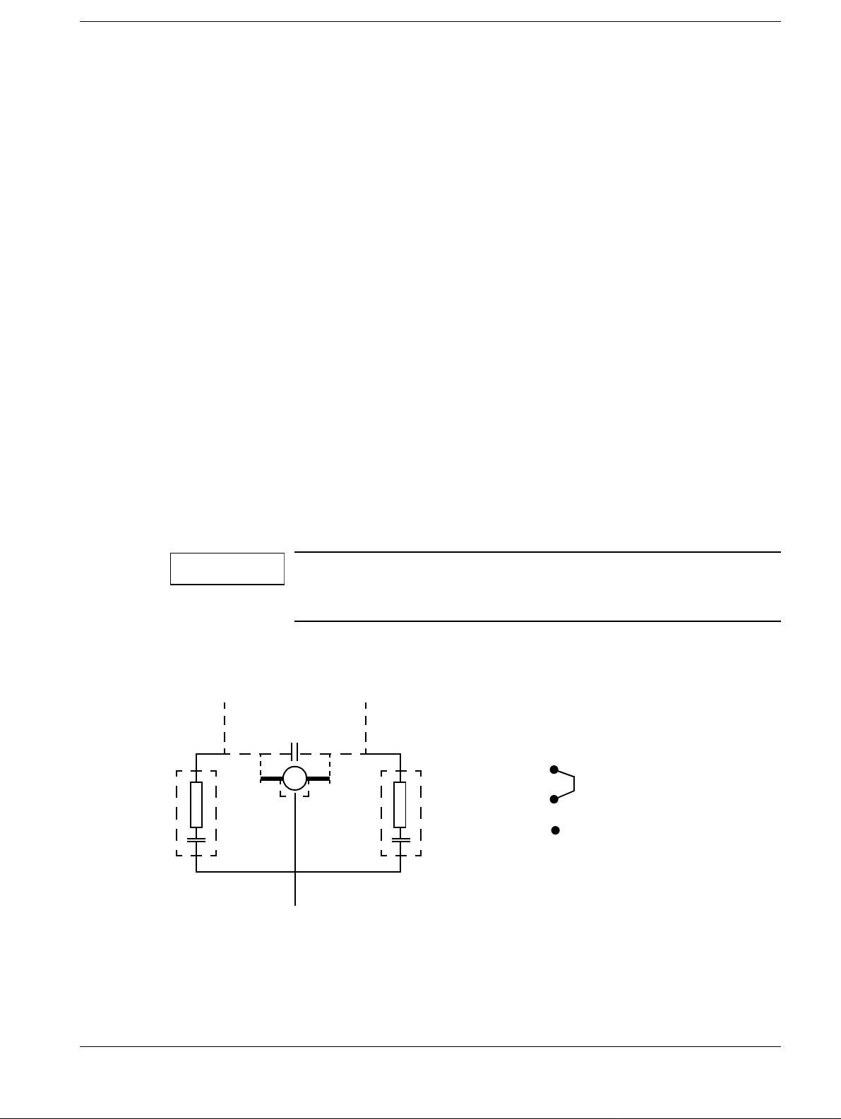
Suppression of light distributor (220 V, not for I.I.40) 2
Voltage peaks caused by switching off the motor voltage of the
mirror motor in the light distributor result in generator interferences
• For the reason, generally incorporate two RC element s, Part No.31 33 147 B2003
parallel to the motor.
For 220V mirror motor voltage, reconnect
jumper x7 on board D271
M 8.7
M
M 8.8
100Ω
0.22µF
x7
3
24V mirror (40cm I.I.)
2
220V mirror
1
M 8.3
Siemens AG TD AX 6 RX63-050.034.12 Register 4 POLYDOROS SX
Medical Engineering Rev. 01 05.96
Page 10

Chapter 2Preparations for dose rate setting
Page 2 of 4
Fluoroscopic dose rate
(Excerpt from "Test Certificate for Fluoro and DFR/DR Systems")
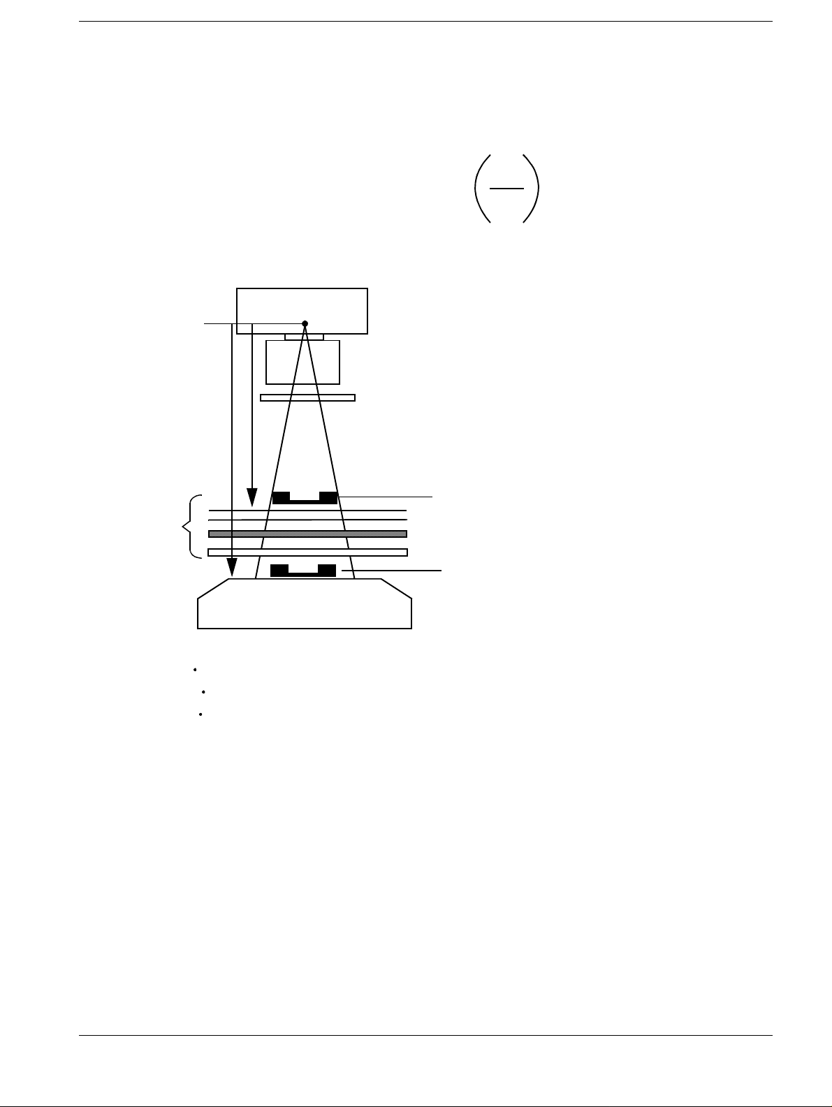
Basic info on dose/dose rate measurement on image intensifier workstations
For dose measurement at the I.I. input (K
( ), attach the dose measuring chamber centrally to the radiation field, as close as pos-
K
B
sible to the I.I.; in the case of spotfil m devices, place it in the cassette shaft. If this is not
possible, measure the dose (K
) or the dose rate ( ) in front of the attenuating layers:
Tg
- With OT units on the tabletop
- With UT units on the spotfilm device rear panel
- With C-arm units on the grid
Using the correction factor m (unit attenuation factor), the value at the I.I. input is calculated.
The unit attenuation factor contains all attenuating layers between the patient and the
image receptor , inc luding t he distan ce fac tor; i t is i ndic ated in th e unit tes t certif icat es and
can also be calculated by multiplication of the attenuation factors of all individual layers.
The radiation attenuation of 6% resulting from the dose measuring chamber must be
taken into account as well (factor 0.94).
Determination of the dose/dose rate directly at the I.I. input
) or dose rate measurement at the I.I. input
B
K
Tg
2
Dose Dose rate
Meas. chamber in the I.I. plane K
Meas. chamber in front of K
=KBg x 0,94 = x 0,94
B
x 0,94 x 0,94
K
TG
==
B
K
B
K
B
K
Bg
K
Tg
attenuating layers mm
Special case 1: Dose rate measurement if the ADC measuring field is larger than
the dose measuring chamber:
Allow the ADC to adjust with 2.1 mm Cu prefi ltration, chan ge over to ST OP , now place
the dose measuring chamber in the beam path and measure the dose rate. The factor of
0.94 must not be taken into account in this case.
Special case 2: Dose measurement if the dominant is larger than the dose measuring chamber:
Place 2.1 mm Cu and the dose measuring chamber in the beam path, release an exposure and measure the dose (KBg or KTg) and the mAs value (Qg1). Remove the dosimeter from the beam path, release an exposure and measure the mAs value (Qg2).
Calculate the dose at the I.I. input (KB)
Q
KB=K
POLYDOROS SX Register 4 RX63-050.034.12 TD AX 6 Siemens AG
Rev. 01 05.96 Medical Engineering
x ;KB= x
Bg
Q
g2
g1
K
m
Tg
Q
Q
g2
g1
Page 11
Preparations for dose rate setti ng Chapter 2
s
Page 3 of 4
Determining the unit attenuation factor from the indi vidual attenuation factors
m
unit
attenuation
factor
Attenuation factor of tabletop, spotfilm device rear panel etc. m
Attenuation factor of scattered radiation grid m
Attenuation factor of Iontomat chamber m
2
r
Attenuation factor distance factor mA =
B
r
T
Unit attenuation factor m = mT x mR x m? x mA . . . . . . .
Cu filter
r
B
r
T
K
Tg
Measuring chamber in front of attenuating layer
Tabletop or spotfilm device rear panel
Grid
Iontomat chamber
K
Bg
K
B
Measuring chamber in I.I. plane (cassette shaft)
I.I. input
T
R
I
/ = Dos e /dose rate directly at the I.I. input
K
K
B
B
/ = Measured dose/dose rate in the I.I. plane
K
K
Bg
Bg
/ = Measured dose/dose rate in front of the attenuating layers
K
K
Tg
Tg
r
B
r
T
= Source-image receptor distan ce
= Distance between source and beginning of the attenuati ng layers
Siemens AG TD AX 6 RX63-050.034.12 Register 4 POLYDOROS SX
Medical Engineering Rev. 01 05.96
Page 12

Chapter 2Preparations for dose rate setting
Page 4 of 4
Formulas for calculating the dose/dose rate in the measuring plane for the dose/
dose rate setting
During setting, the dose or dose rate required directly at the I.I. input must be converted
into the measuring plane (I.I. plane or in front of the attenuating layers). For this, use the
modified fo rmulas. .
Dose
K
Meas.chamb. in I.I.plane KBg==
B
0.94
Dose rate
K
B
K
Bg
0.94
Meas.chamber in front of
attenuating layers K
K
==
Tg
B
0.94
K
Tg
K
B
0.94
x m
x m
Remark: The radiation attenuation resulting from the dose measuring chamber is already
taken into account during setting
(for adjustment: remove the dose measuring chamber from the beam path).
Do not use the f actor of 0.94 for calculating the dose r ate to be set.If the dose/
dose rate is checked (not set), the factor of 0.94 must be taken into account.
Example for determining the correction factor
Correction factor m (total) =
(source-I.I. distance/source-measuring chamber distance)
2
x m-factor (Iontomat camber) x m-factor (Raster)
x m-factor (tabletop etc., if between dose measuring chamber and I.I.) etc.
- Distance correction factor (m
source-I.I. distance( rB)
source-meas. chamber distance(rT)
) =
A
2
Example:
100
2
=1.17
92.5
- Grid correction factor (m
- IONTOMAT chamber correct. factor (m
- Tabletop correct ion factor (m
) = 1.7
R
)= 1.1
I
) = 1.1
T
When setting the dose/dose rate, multiply the dose/dose rate required at the I.I.
input by the correction factors.
e.g. 174 nGy/s x (m
A
x m
R
x m
x mT)
I
174 nGy/s x (1.17 x 1.7 x 1.1 x 1.1) =
174 nGy/s x 2.4 = 408 nGy/s
µR=8.7 nGy)
(1
Record the correction factor m in Chapter 4.1 of the "Test Certificate for DL and DFR/DR
Systems".
The test certificate is filed in Register 9 of the System or Generator Binder.
POLYDOROS SX Register 4 RX63-050.034.12 TD AX 6 Siemens AG
Rev. 01 05.96 Medical Engineering
Page 13

NOTICE
Startup 3
Programming the POLYMATIC 3
General Remarks 3
In system shipments, the programming has already been carried out at the factory.
In subsystems, the expansions to be connected during start-up must be programmed
appropriately.
File the test certificate"Fluoro and DFR/DR Systems", RXD0-
000.037.01... in Register 9 of the System or the Generator Binder.
A help function is available in the Service Software beginni ng with Service Software
VE00A.
• By clicking on the "HELP" box in the particular window or
• by pressing the "F1" function key on the PC or
• in the "Help" / "Index" in the main menu
valuable information and the required programming and entries can be selected.
Chapter 3
Page 1 of 22
Programming 3
1 Establishing the Generator - Service PC Connection
2 "System" / "Connect"
3 "Configuration" / "Options..." / "Page 2..."
• Set the dose and dose rate units of measurement.
4 "Configuration" / "Unit Selection" / "Button 1..."
Siemens AG TD AX 6 RX63-050.034.12 Register 4 POLYDOROS SX
Medical Engineering Rev. 01 05.96
Page 14

Chapter 3Startup
Page 2 of 22
Fluoroscopy Programming 3
The Test Certificate "Fluoro and DFR/DR Systems", RXD0-000.037.01... is filed in
Register 9 of the System or Generator Binder.
• Select "Fluoroscopy" (if not already sel ected!)
• Select "FC-Details..."
• Appropriately program the "Primary FC-Data" and con firm with "OK".
• Appropriately program the "VIDEOMATIC P" and confirm with "OK".
• Record the values programmed in the Test Certificate:
SID (focus-I.I. distance) in Chapters 4 and 4.2,
Over-table units: 115 cm
Under-table units: max. SID (do not move out the Distator)
C-Arm units: 100 cm
I.I. formats in Chapter 4.1.2
Zoom dose rate (Zoom dose factors) in Chapters 4.1.2 and 4.2
Dose rate in Chapters 4.1 and 4.2
The fluoroscopy curves used by the customer in Chapter 4.2.
Additional Information: 3
• "maximum fluoro rate":
- Therapy Simulation: OPTILIX 150/12/50 C: max. 1000 W
- High Contrast Fluoro: MEGALIX 125/40/82 C: max. 1200 W
(with HV generators beginning with Ser. No. 01056 max. 2000 W)
with the fluoro footswitch wit h the 2nd pressure point
- "Normal Fluoro" all other X- ray tubes max. 450 W
• When the image intensifier model is selected, al l input boxes are assigned default
values (see also the IQ reference value l ist).
• The dose rate selected is always relative to the full format
(largest I.I. form at!)!
• Program the same dose rate values for Automatic 1 and 2
• Fluoroscopy blocking: "Block on"
according to regulations in Germany and in DHHS countries, fluoroscopy must be
blocked after 5 minutes.
• If fluoroscopy is configured after the "test shots" of the X-ray tube, the X- ray tube test
shots must be carried out again
("Adjustment"/"Tube 1... "/"PT Emulation...": Module J05, J0 6 and J07")!
POLYDOROS SX Register 4 RX63-050.034.12 TD AX 6 Siemens AG
Rev. 01 05.96 Medical Engineering
Page 15
Startup Chapter 3
Page 3 of 22
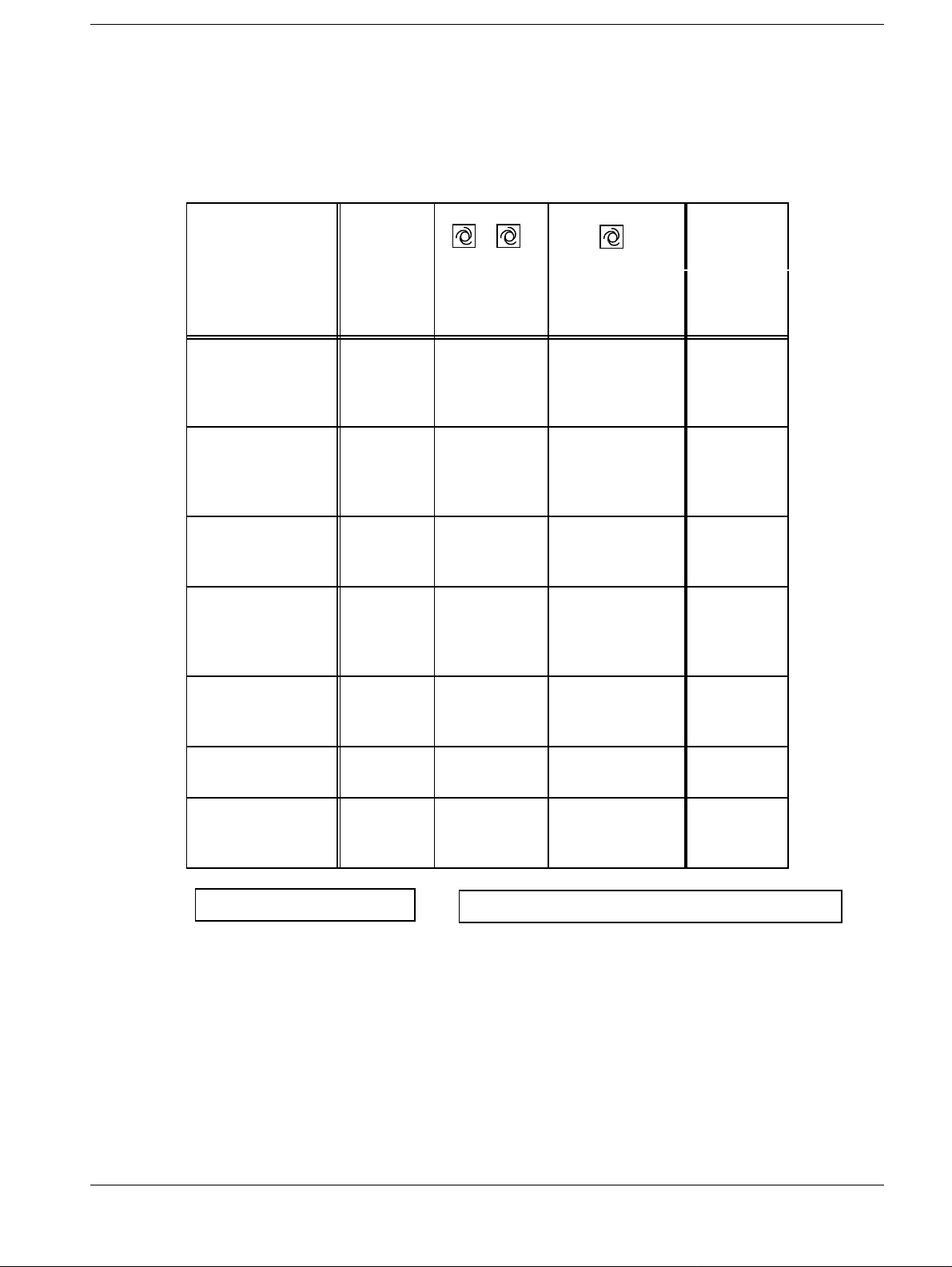
Excerpt from the "Reference Value List for Fluoro and DFR/DR
Systems":
Fluoroscopy dose rate at the I.I. input 3
2.1 mm Cu filter, X-ray tube voltage 65 - 85 kV
Zoom Dose
Factors
PL SX
50/80
1:
2.0:
4.0:
5.0
1:
1.8:
3.3:
5.5
1:
2.1:
3.8
BV-Typ /
I.I. Type
40 cm HD 40
40 cm HDR 40
33 cm HD 33
Formate /
Formats
28
20
14
30
22
17
23
17
1, 2
Dosisleistg.
Dose rate
(nGy/s)
87
160
315
(435)
87
120
255
440
113
240
450
3
Hochkontrast /
High cont rast
(nGy/s)
139
255
505
(695)
139
195
405
700
3
33 cm HDR 33
22
17
13
27 cm 27
17
14
Sirec.Komp.
(alt/old)
23 cm HDR/HDLE
Sirec.Komp.
(neu/new)
U
Multiplier
Tolerance: I.I. full format
Tolerance of indirect dose rate control
Values in brackets ( ) apply if TV iris diaphragm is configured.
Urology: With TV iris diaphragm for Automatic 2, set doubl e the dose rate.
= 700 – 950 V
22
17
23
17
13
± 10%; at Zoom formats approximate value only.
113
235
405
680 (430)
174
445
655 (435)
261
435
261
440
730 (470)
*1
1 nGy/s = 0.115 µR/s / 1 µR/s = 8.7 nGy/s
±1 kV, mA: ±10%
1:
2.3:
3.8:
6.4 (3.8)
1:
2.5:
3.7 (2.5)
1:
1.7
1:
1.8:
3.1 (1.8)
*1 effecti ve beginning 7.93 (possible only with masked Multiplier)
Siemens AG TD AX 6 RX63-050.034.12 Register 4 POLYDOROS SX
Medical Engineering Rev. 01 05.96
Page 16

Chapter 3Startup
Page 4 of 22
DR Programming (if Configured) 3
The Test Certificate for "Fluoro and DFR/DR Systems", RXD0-000.037.01... is filed in
Register 9 of the System or Generator Binder.
Select "DR" (if not already selected!)
• Select "DR-Details".
• Appropriately program the DR settings and confirm with "OK".
• Record the values programmed in the Test Certificate, Chap ter 8.
Excerpt from the Reference Value List for "Fluoro and DFR/DR Systems": 3
BV-/ I.I.
Format
(cm)
40 HD
28
20
14
40 HDR
30
22
17
33 HD
23
17
33 HDR
22
17
13
27
17
14
Dose
50
(nGy/F)
215
400
790
1090
215
305
635
1095
305
650
1220
305
635
1095
1095
435
1110
1110
Dose
100
(nGy/F)
435
800
1580
2175
435
610
1270
2190
610
1305
2440
610
1270
2190
2190
870
2220
2220
Dose
200
(nGy/F)
870
1600
3160
4350
870
1220
2540
4385
1220
2610
4880
1220
2540
4385
4385
1740
4440
4440
Dose
500
(nGy/F)
2175
4000
7900
10900
2175
3045
6350
10960
3040
6525
12200
3050
6350
10960
10960
4350
11100
11100
Zoom-Dose
Factors
PL SX 50/80
0.5:
1.0:
2.0:
2.5
0.5:
0.8:
1.5:
2.5
0.7:
1.4:
2.5
0.7:
1.5:
2.5:
2.5
1.0:
2.5:
2.5
23 HDR
17
13
U
Multiplier
*1effectiv beginning 07.93 (possible only with masked Multiplier)
Tolerance
At indirect dose measurement:Tolerance
Tolerance for reproducibility at DSA (8/F/s; Dose 500):
POLYDOROS SX Register 4 RX63-050.034.12 TD AX 6 Siemens AG
Rev. 01 05.96 Medical Engineering
± 15% (DSA-Dose 500 + 15% / -20%)
610
1020
1020
≥ 450 V*1 1 nGy = 0,115 µR / 1 µR = 8,7 nGy
1220
2045
2045
2440
4090
4090
6100
10225
10225
±15% of the mAs value.
∆ ≤ 20% of Average
1.4:
2.5:
2.5
Page 17

Startup Chapter 3
Page 5 of 22
SIRCAM Programming (if Configured) 3
The Test Certificate for "Fluoro and DFR/DR Systems", RXD0-000.037.01... is filed in
Register 9 of the System or Generator Binder.
Select "SIRCAM" (if not already selected! )
Select "Sirc-Details".
• Program the SIRCAM settings appropriat ely and confirm with "OK".
• Record the values programmed in the Test Certi ficate:
- Zoom dose rate (Zoom Dose Factor) in Chapter 7.1.1. 2
- Dose (SIRCAM dose) in Chapter 7.1.1
Excerpt from the Reference Value List for "Fluoro and DFR/DR Systems: 3
POLYDOROS SX 50/80
BV-Type
I.I. Type
Formate
formats
Dosis
Dose
(nGy)
Zoom Dose
Factors
40 cm HD 40
28
20
14
33 cm HD 33
23
17
33 cm HDR 33
22
17
13
27 cm 27
17
14
23 cm HDR 23
17
13
U
Multiplier
≥ 450 V*1 1 nGy = 0.115 µR / 1 µR = 8.7 nGy
218
400
790
1600 (1090)
261
560
1050
261
545
1010
1565 (990)
435
1110
1635 (1090)
574
965
1610 (1030)
1
2
4
8.2 (5)
1
2.1
3.8
1
2.3
3.8
6.4 (3.8)
1
2.5
3.7 (2.5)
1:
1.8:
3.1 (1.8)
Tolerance: ± 15%, at Zoom formats approximate value only.
At indirect dose measurement: Tolerance
Values in brackets ( ) apply if I.I exposur e diaphragm is configured.
*1 effective beginning 07.93 (possible only with masked Multiplier)
Siemens AG TD AX 6 RX63-050.034.12 Register 4 POLYDOROS SX
Medical Engineering Rev. 01 05.96
±15% of the mAs value.
Page 18

Chapter 3Startup
IMPORTANT
Page 6 of 22
Configuration" / "IONTOMAT..." 3
The detector allocation must be carried out for the "Indirect Ionto channel":
• Choose "FC-Channel" (set in "Configurati on" / "Unitselection" / "Butt on 1..." "FC-
Details...")
• Select "CHANNEL Prog."
• Choose "Detector"
possible detectors: Mult iplier or B-S ignal or PDA (Photo Diode Array)
Remark for PDA:
"Invert MF": not selected with SIREGRAPH CF
selected with POLYSTAR
"Data" / "Restore" 3
After completing programming, download the system configuration from the PC to the
generator.
Changes made in the "Configuration" main menu are effective
only after a "Data" / "Restore" in the generator.
POLYDOROS SX Register 4 RX63-050.034.12 TD AX 6 Siemens AG
Rev. 01 05.96 Medical Engineering
Page 19
Startup Chapter 3
Page 7 of 22
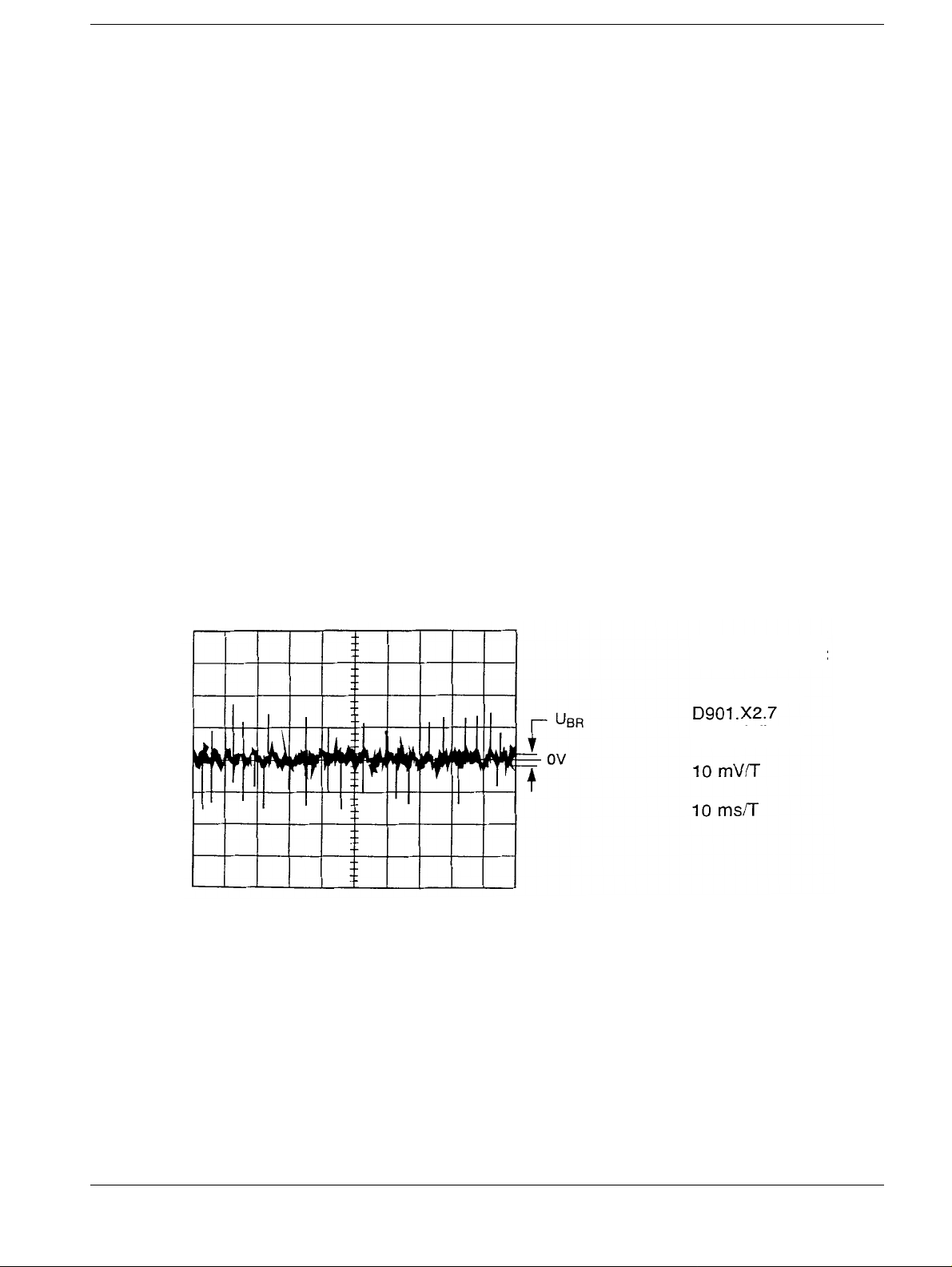
IONTOMAT P: Checking Drift and Hum (Ripple) during
Fluoroscopy
• Switch SS OFF.
• Connect the oscilloscope to D901.X2.7 and D901. X2.1 (0 V)
Trigger: D211.SWR
• Select the fluoro unit at the control deck.
a) Checking the Drift (without radiation)
• Switch on fluoroscopy at the unit and measure dri ft for 1 minute.
Max. admissible drift:
• Switch off fluoroscopy.
b) Checking the Hum (Ripple) (without radiation)
• Switch on fluoroscopy at the unit and measure the hum ( ripple).
Max. admissible hum:
• Switch off fluoroscopy.
After completing the measurements:
• Disconnect the oscilloscope test leads.
• Switch SS ON
Enter the measurement results in the "Test Certificate for Direct Exposure Units"
RXD0-000.037.05... Chapter 4 (in Register 9 of the System or Generator Binder).
≤ ±20 mV/min.
≤ 20 mV
(per oscillogram 2).
ss
3
Oscillogram 2:
Noise at
(Example)
Siemens AG TD AX 6 RX63-050.034.12 Register 4 POLYDOROS SX
Medical Engineering Rev. 01 05.96
Page 20

Chapter 3Startup
NOTICE
Page 8 of 22
Adjusting the Dose Rate 3
General Remarks 3
Three types of dose rate control are possible with the POLYDOROS SX 50/80.
The following detectors can be connected:
a) Multiplier (Photo-)
b) PDA (Photo Diode Array)
c) B-Signal (SIRECON Kompakt, Videomed DI-K)
The Test Certificate for "Fluoro and DFR/DR Systems", RXD0-
000.037.01... is filed in Register 9 of the System or Gene rator
Binder .
POLYDOROS SX Register 4 RX63-050.034.12 TD AX 6 Siemens AG
Rev. 01 05.96 Medical Engineering
Page 21

Startup Chapter 3
NOTICE
Page 9 of 22
a) Adjusting the Dose Rate with the Multiplier
Preparations (Test Setup)
• Select I.I. full format.
• Set the SID
Over-table units: 115 cm
Under-table units: max. SID (Distat or not moved out)
C-Arm units: 100 cm
• Insert 1.2 mm copper in the collimator
• Place the dose measurement chamber so that it is c entered on the I.I.
• Collimate to the size of the dose measurement chamber.
Adjustment
• At the Service PC, after "System" / "Connect "
select "Adjustment" / "Doserate"
• Record the amount of copper inserted into t he collimator in the appropriate i nput window
"CU:
• Carry out Adjustment of the Dose Rate: 174 nGy/s (20 µR/s) usi ng the prompted
routine in the Service Software.
[mm]" (only a display! - no functio n).
• After the display "EEPROM Status ok" appears, the values in the field: "Status" are
stored in the generator.
• Record the values that result in the Te st Certificate:
- MPL Area 1 in Chapter 4 and for
- MPL Area 2 in Chapter 8.1
• Use "Leave Module" to exit the adjusmtent module "Dose rate".
At the Service PC: select "System" / "Disconnect".
The actions to be made are displayed in the field: "User action".
Commands are sent to the generator using the switch box located
just below this, e.g.: starting the adjustment with the switch box:
"Start Measuring".
The values of the current or of the last adjustment are displaye d n
the field marked "Data.
Always switch fluoroscopy ON/OFF from the D211 board.
Use the "
nGy/s (20
factor (see Chapter 2). The next adjustment is started using this
tube current.
Carry out adjustment of the dose rate 174 nGy/s (20
accurately as possible because all dose and dose rate values are
derived from this adjustment.
With the automatic adjustments for multipl ier ranges "1" (20
and "2" (250
tiplier voltages adjusted are displayed in the "Data" field (admissible deviation: +/- 1).
←" and "→" keys to change the tube current until 174
µR/s) is measured - take note of the unit attenuation
µR/s) as
µR/s), an adjustment must be achieved, i.e., the mul-
µR/s)
Siemens AG TD AX 6 RX63-050.034.12 Register 4 POLYDOROS SX
Medical Engineering Rev. 01 05.96
Page 22

Chapter 3Startup
Page 10 of 22
b) Adjusting the Dose Rate with the PDA/SDM
Additional information about the PDA (Photo Diode Array) and SDM (Selective Dominant
Measurement) can be found in the Appendix.
Preparations (Test Setup)
• Connect the DVM to D901 X2.1 (0V) and X2.7 ( Signal):
Nominal value: 0V +/-10 mV in the Standby mode (Fl uoro OFF)
If the display is > 10 mV, it is pos sible that too much external light is r eaching the PDA.
Corrective measure: install the co ver panels on the light distri butor.
• Select the I.I. full format and Automatic 1.
• Select the middle, rectangular measuring fi eld.
• Set the SID:
OT units = 115 cm
UT units = max. distance
Polystar = 100 cm
• Insert 1.2 mm Cu in the collimator
• Position the dose measurement chamber so that it is centered on the I .I.
• Collimate to the size of the dose measuring chamber.
Preadjustment - "PDA Preadjust"
• At the Service PC after "System" / "Connect",
select "Adjustment" / "Doserate"
• Record the amount of copper inserted into the col limator in the appropriate entr y box
"Cu:
[mm]" (display only ! - no funct ion).
• Carry out the adjustment of dose rate using the prompt ed routine from the service
software.
• Click on the switch box "Start Measuring" .
• Use the S1 on the D211 board to start fluoroscopy.
• Set 870 nGy/s ( 100 µR/S) at the I.I. input by increasing the tube current*
This tube current is used to start the next adjustment.
• *Caution: take note of the unit attenuation factor
Polystar: 1.8 --> 1566 nGy/s (180
Siregraph CF: 1.0 --> 870 nGy/s (100 µR/s)
µR/s)
• Click on the switch box "Stop DR".
• Switch fluoro OFF and remove the dose measuring chamber.
• Open the collimator all the way.
D100 Camera Adapter
• Connect the DVM to D901.X2.1 and X2.7.
• "Start FS" (switch fluoro on) with D211, S1
• Use R1 on D100 in the camera adapter
to set 700 mV +/- 35 mV
if needed, switch to the amplific ation (factor: 4)
usign the S2 on the D100. When this is done,
the S1 fluoroscopy switch on the D21can be
switched on and off as often as wished.
• Install the housing over the light di stributor.
• Recheck the 700 mV setting.
• "Please STOP FC"
• Stop Preadjust
• Deselect "PDA Preadjust".
3
POLYDOROS SX Register 4 RX63-050.034.12 TD AX 6 Siemens AG
Rev. 01 05.96 Medical Engineering
Page 23
Startup Chapter 3
NOTICE
Page 11 of 22
Carrying Out the Sensitivity Adjustment
• Open the collimator all the way.
• Select I.I. full format.
• "Please Start FC":Fluoro ON with S1/D211 (i n the generator).
The adjustment is carried out automati cally for all I.I. formats and measur ing field
combinations (9). Fluoroscopy will be i nterrupted automatically for ap prox. 1 second
between the individual adjustments.
• "Please Stop FC":Fluoro OFF, S1/D211.
• Select the next Zoom step.
• Carry out the adjustment for each Zoom step.
• The values will be stored in the generator fol lowing the display "EEPROM Status ok" in
the field: "Status".
• The "Doserate" adjustment module is exit ed by selecting "Leave Module".
• At the Service PC: select "System" / "Discon nect".
3
In the field: "User action" (actions carr ied out by the user) the
steps that must be carried out are displayed.
Commands are sent to the generator by clicking on the switch
box located just below this field, e.g.: starting the adjustment by
clicking on the switch box: "Start Measuring"
Always switch fluoroscopy ON/OFF from the D211 board.
Use the "
870 nGy/s (100
Take note of the unit attenuation factor (see Chapter 2).
Carry out the dose adjustment of 870 nGy/s (100
rately as possible because all dose and dose rate values are
derived from this value.
Automatic adjustment will be carried out for all I.I. formats and for
all possible measuring field combinations. The values of the current or of the last adjustment are displayed in the field: "Data" /
"PDA Data".
The maximum "+" and "-" difference is around +/- 8.
The absolute difference - in the full format - betwee n the left center and right measuring field is about +/- 16.
←" and "→" keys to change the tube current until
µR/s) is measured.
µR/s) as accu-
Siemens AG TD AX 6 RX63-050.034.12 Register 4 POLYDOROS SX
Medical Engineering Rev. 01 05.96
Page 24

Chapter 3Startup
NOTICES
Page 12 of 22
c) Adjusting the Dose Rate Using the B-Signal
Preparations (Test Setup)
• Select the I.I. full format.
• Set the SID:
Over-table units: 115 cm
Under-table units: max. SID (do not move out the Distator)
C-Arm units: 100 cm
• Insert 1.2 mm copper in the collimator.
• Position the dose measuring chamber so that it is centered on the I.I.
• Collimate to the size of the dose measuring chamber.
Adjustment
• At the Service PC, following "System" / "Connect"
select "Adjustment" / "Doserate"
• Record the amount of copper inserted into the col limator in the appropriate input box
"Cu:
[mm]" (display only! - no func tion).
• Adjust the Dose rate to 260 nGy/s (30 µR/s) using the prompted r outine in the service
software.
• The values are stored in the generator after the mess age "EEPROM Status ok" is
displayed in the field: "Stat us".
• Exit the "Doserate" adjustment module by click ing on "Leave Module".
• At the Service PC: select "System" / "Disconnect ".
The steps to be carried out are displayed in the field: "User
action" (actions performed by the user).
Commands are sent to the generator by clicking on the switch
box directly below this fi eld, e.g.:Starting the adjustm ent with the
switch box: "Start Measuring"
The values of the current or of the last adjustment are displayed
in the field: "Data".
Fluoroscopy is switched on and off twice during the adjustment.
Please make sure to maintain the following sequence:
Step 1: Switch Fluoro ON at the unit (enables the TV channel)
Step 2: Switch Fluoro ON at board D211(enables radiation)
Step 3: Switch Fluoro OFF at board D211
Step 4: Switch Fluoro OFF at the unit
POLYDOROS SX Register 4 RX63-050.034.12 TD AX 6 Siemens AG
Rev. 01 05.96 Medical Engineering
Use the "
260 nGy/s (30
Take the unit attenuation factor into accound (see chapter 2).
Perform adjustment for the dose rate as accurately as possible.
←" and "→" keys to change the tube current until
µR/s) is measured.
Page 25
Startup Chapter 3
NOTICE
Page 13 of 22
Checking the Dose Rate for Fluoroscopy 3
Preparations (Test Setup) 3
• For Automatic 1, temporarily program the C00 fl uoro curve
("Configuration" / "Uni t selection" / "Button 1..." / "FC-Details..."/"Videomat ic P"
then "Data" / "Restore")
• Insert the 2.1 mm Precision copper filt er in the collimator
(with under-table units, place it on the tabletop)
• Set the SID:
Over-table units: 115 cm
Under-table units: max. SID (do not move out the Distator)
C-Arm units: 100 cm
• Select Automatic 1 and I.I. full for mat.
• Move in the grid.
• With the 40 cm I.I.:
with the multiplier: select the round ADC measuring field in the middle;
with the PDA/SDM: select the rectangular measuring field.
• Position the dose measuring chamber so that it is center ed on the I.I. and collimate to
the size of the dose measuring chamber.
If it is not possible to meas ure directly at the I.I. i nput, measure on
the tabletop or at the back wall of the spotfilm device or on the
grid and use the unit attenuation factor (m) to calculate for the I.I.
input.
The cassette loading slot on the spotfilm device appl ies as the I.I.
input (see also Chapter 2).
With TV systems in which the ADC measuring field is larger than
the dose measurement chamber, a switch to automatic STOP
must take place after fluoroscopy has stabilize d and the n move
the dose measuring chamber into the beam path. In t his case, the
factor 0.94 for radiation attenuation of the dose measuring chamber does not need to be taken into consideration.
First enter the measured dose rates ( or ) into the Test Certificate and then the calculate the corrected value K
With the 12 cm and 14 cm I.I. format (if not measured directly at
the I.I. input) the dose measuring chamber is not fully exposed.
Thus, the measured dose rate values are lower than the actual
values.
Record this fact under remarks in the Test Certificate, Chapter
4.1.2.
K
Bg
K
Tg
and enter it.
B
Siemens AG TD AX 6 RX63-050.034.12 Register 4 POLYDOROS SX
Medical Engineering Rev. 01 05.96
Page 26

Chapter 3Startup
Page 14 of 22
Check 3
The Test Certificate "Fluoro and DFR/DR Systems", RXD0-000.037.01... is filed in
Register 9 of the Generator Binder.
• Switch on fluoroscopy at the unit.
• Measure the dose rate values for all I.I. fo rmats ( or ) and enter the values in the
Test Certificate, Chapter 4.1.2.
Admissible deviation with I.I . full format: +/- 10%; relativ e to the dose rate programmed
under "Configuration" / "Uni t selection" / "FC-Detail s" / "Vidomatic P" ! (for Zoom
formats, these are only refer ence values!)
K
Bg
K
Tg
• Remove the dose measuring chamber from the beam path.
• Open the collimator all the way.
• Record the kV and mA values which adjust under fluorosc opy (display on control
console) for all I.I. for mats i n the Test Certificate, Chapter 4.1.2.
Admissible tolerance for i ndirect dose check: +/- 1 kV; mA: +/- 10 %
POLYDOROS SX Register 4 RX63-050.034.12 TD AX 6 Siemens AG
Rev. 01 05.96 Medical Engineering
Page 27

Startup Chapter 3
Note
Page 15 of 22
Checking the Dose/Image for SIRCAM 3
• Connect the mAs meter.
• For the test setup, see "Checking the Dose Rate".
• Select SIRCAM .
• Call up (or generate) zero-point technique or gan program
- small focus
- 1 f/s or single frame
- 70 kV plateau (C14, selectable with the ms buttons)
• Measure and record in the Test Certificate, Chapter 7.1.1.2 (K
the dose measuring device does not deflec t enough, make several exposures and
divide the measured dose value by the number of exposu res.
or KTg). If the pointer of
Bg
• Calculate and record the dose at the I.I. input :
= K
K
B
Bg
Factor 0.94 = 6% radiation attenuation caused by dose measuring chamber.
x 0.94; KB = KTg x 0.94
m
• Remove the dose measuring chamber from the beam path and record the in dicated kV
values and resulting mAs values and the r esulting mAs values for each single exposure
for all I.I. formats in th e Test Certificate (Chapter 7. 1.1.2).
With 12 cm I.I. format and 14 cm I.I. format (if measurement is not
performed directly at the I.I. input), the dose measuring chamber
is not exposed completely. As a result, the measured dose rate
values are lower than the actual values. Indicate this fact under
"remarks" in the Test Certificate.
Siemens AG TD AX 6 RX63-050.034.12 Register 4 POLYDOROS SX
Medical Engineering Rev. 01 05.96
Page 28
Chapter 3Startup
NOTICE
Page 16 of 22
Setting the Maximum Skin Dose Rate 3
In accordance with the country-specifi c regulations, set the maximum admissible
values.
In DHHS countries, set for
- "Hand kV": 4.5 R/min (660 nGy/s)
- "Normal Fluoroscopy 9.0 R/min (13200 nGy/s)
- "High Contrast Fluoroscopy": 18.0 R/min (2620 nGy/s)
If no such r egulations exist, car ry out the modul e with "SS" swi tched OFF. For 1 10 kV and
70 kV, set 18 mA
Preparations (Test Setup) 3
• Select the I.I. full format.
• Set the minimum SID:
- Over-table units: 115 cm
- Under-table units: min. SID (do not mo ve out the Distator)
- C-Arm units: min. SID (POLYSTAR. 86.6 cm)
• Insert 1.2 mm copper into the collimator.
for each.
• Position the dose measuring chamber, with
- Over-table units at a distance of 30 cm above the tabletop
- Under-table units on the tabletop
- C-Arm units at a distance of 30 cm above the I. I.
This distance must be maintained - regard less of the SID.
• Collimate to the size of the dose measuring chamber.
• Remove the fuses in the I.I. power supply (risk of bur n-in).
Adjustment 3
At the Service PC, after "System" / "Connect "
select "Adjustment" / "Skindoserate"
If reduced skin dose rate (5 R/Min.; 733
kV Hand and/or Automatic/HC, mark the appropriate field prior
the adjustment:
µGy/s) must be used for
to
• Carry out the adjustment of maximum skin dose rate (SDR) by f ollowing the prompted
routine in the service software.
POLYDOROS SX Register 4 RX63-050.034.12 TD AX 6 Siemens AG
Rev. 01 05.96 Medical Engineering
Page 29
Startup Chapter 3
NOTICES
Page 17 of 22
The steps to be carried out are displayed in the field: "User
action" (actions performed by the user).
Commands are sent to the generator in the switch box directly
under this field, e.g.: Start ing the adj ust ment with the s witch b ox:
"Start Measuring"
The values of the current or the last adjustment are displayed in
the field: "Data".
Use the "
maximum skin dose rate of 9 R/min (1320
If there are no regulations to limit the maximum skin dose rate,
set 18 mA.
The values are stored in the generator after the message
"EEPROM Status ok" is displayed in the field: "Status".
Exit the "Skindoserate" adjustment module with "Leave Module".
At the Service-PC: select "System" / "Disconnect".
←" and "→" keys to change the tube current until the
µGy/s) is measured.
Final Check of the Skin Dose Rate 3
The Test Certificate "Fluoro and DFR/DR Systems", RXD0-000.037.01... is filed in
Register 9 of the System- or Generator binder.
• Retain the distance between the dose measuring chambe r and the I.I.
• Change the SID and check the dose rate.
• At no SID may the dose rate of 9 R/min be exceeded.
• Select I.I. full format.
• Set the minimum SID.
• Select all Automatic steps (if confi gured, also using the second pressur e point).
• Record the values that result f orr
- dose rate and
- the kV and mA values (display on the control console)
in the Test Certificate, Chapter 4.4 .2.
• Reinstall the fuses in the I.I. power supply.
Siemens AG TD AX 6 RX63-050.034.12 Register 4 POLYDOROS SX
Medical Engineering Rev. 01 05.96
Page 30

Chapter 3Startup
NOTICE
NOTICE
Page 18 of 22
Calibrating the Acquisition (Poly-I.I. Adaption) 3
Preparations (Test Conditions) 3
• Insert the 20 cm water phantom - maintain exactly - into the beam path.
• Set the SID:
- Over-table units: 115 cm
- Under-table units: max. SID (do not move ou t the Distator)
- C-Arm units: 100 cm
• Select the I.I. full format.
• Move in the grid.
• With the 40 cm I.I.:
with multiplier: select the rou nd, middle ADC measuring field
with PDA/SDM: select the rectangula r measuring field in the middle
• Assign any organ field with the C00 acquisitio n curve (Fluorospot H: C29) and select i t.
Curve C00/C29 is intended exclusively for calibration and should
not be used for the "normal" exposure mode.
• Collimate to the size of the water phantom.
Check 3
• Switch on fluoroscopy (from the unit).
70 kV must adjust as the exposure voltage; admissible tolerance: +/- 1 kV.
• With deviations from this tolerance: sel ect "Adjustment" / "Poly-I.I . Adaptation"
do not carry out "System" / "Connect" (g enerator is not in the service mode).
• Carry out the adjustment by following the prompted routine in the service software.
• The values are stored in the generator after the mess age "EEPROM Status ok" is
displayed in the field: "Stat us".
• Exit the "Poly-I.I. Adaption" adjustment module with " Leave Module".
• At the Service PC: select "System" / "Disconnect ".
• Repeat the check.
The adjustment can be carried out manually or automatically (by
marking the appropriate box).
Alternately, the deviation can be appropriately corrected in the
window "Primary FC-Data":
Select "System" / "Connect"
Select "Configuration" / "Unit selection" / "Button 1..." / "FCDetails..." / "Videomatic P"/ "Primary FC-Data": correct
Poly-I.I. Adaption.
Select "Data" / "Restore".
Select "System" / "Disconnect".
POLYDOROS SX Register 4 RX63-050.034.12 TD AX 6 Siemens AG
Rev. 01 05.96 Medical Engineering
Page 31

Startup Chapter 3
NOTICE
Page 19 of 22
Adjusting the TV Iris Diaphragm 3
For technical reasons, the "TV Iris diaphragm Adjustment Module" must also be programmed even without the built-in TV iris
diaphragm. However programming is carried out without high
voltage! Switch SS "OFF" on the D200.
Basic adjustment of the "Analog Iris Control" (only if the iris is configured)
D270/D270A Part No. 37 74 697 X2084
a) Adjustment to the "maximum diaphragm opening" with an open control circuit
(basic diaphragm adjustment)
• Remove jumper B (1 - 2).
• Use potentiometer R7 to open the diaphragm until LED V13 l ights up (maximum
opening).
• Turn R7 in the opposite direction until LED V1 3 just goes out.
• Reinstall the jumper B (1 - 2).
• Select "System" / "Connect" and confirm wit h "ok".
• Select "Diagnostics" / "Tests" / " General...".
b) Adjusting the "minimum diaphragm opening" with a closed control circuit
(Basic diaphragm adjustment)
• Select "T92" "Close Iris" and click on "Run".
• Use potentiometer R27 to close the diaphragm until LED V14lights up (minimum
opening).
• Turn R27 in the opposite direction until LED V14 jus t goes out.
c) Adjusting to the "maximum diaphragm opening" with a closed control circuit
(Basic diaphragm adjustment)
• Select "T91" "Open Iris" and click on "Run".
• Use potentiometer R31 to open the diaphragm until LED V13 lights up ( maximum
opening).
• Turn potentiometer R31 in the opposite di rection until LED V13 just goes out.
• Exit the test module.
Siemens AG TD AX 6 RX63-050.034.12 Register 4 POLYDOROS SX
Medical Engineering Rev. 01 05.96
Page 32

Chapter 3Startup
Page 20 of 22
Adjusting the TV Iris Diaphragm 3
Preparations (Test Setup) 3
• Insert 1.2 mm copper in the collimator.
• Set the SID:
- Over-table units: 115 cm
- Under-table units: max. FFA (do not move out the Distator)
- C-Arm units: 100 cm
• Select I.I. full format.
• Move in the grid.
• Open the collimator all the way.
Ausnahmen:
VIDEOMED HD:
- Oszilloskop an TP BAK (VZ-Platine), Tr igger an Ext.A auf AZ-Platine
(bei SUPERVISION Trigger an BAS+)
VIDEOMED K / Sirecon Kompakt:
- Oszilloskop an Meßpunkt M95 / D15 C1 (+) gegen TP F
VIDEOMED DI/DIM/DIK:
- Oszilloskop an Meßpunkt D1, X401
VIDEOMED SX:
- Oszilloskop an TP 8 auf Platine D8 in
• Eine Zeile in Bildmitte (Rauschmitte) mit Zei lenfischer(größere Meßgenauigkeit) tr iggern
Television CCU Camera tube Bias light or
black current portion
Videomed H1X Saticon No DFR: 20, +/- 5 mV
With DFR: 40, +/- 5 mV
Videomed HD DG-Saticon 30 +/- 5 mV 130 mV, +10 / -20 mV*
Videomed H1 Saticon 20 +/- 5 mV 110 mV; +10 / -20 mV
Videomed H1, N1 Hivi con ≤ 100 mV 180 mV, +/ -15 mV
Videomed N1 DG-Saticon 20 +/ -5 mV 110 mV; +10 / -20 mV
Videomed K, Sirecon Kompakt Hivicon n.a. 27 ... 38 mV
Videomed DI/DIM/DIK CCD-Chip n.a. 155 mV; +/- 20 mV
B-Signal without bias light
or black current portion
110 mV; +10 / -20 mV*
Urology:
300 mV; +/- 40 mV
Videomed SX, H1X Emulation Saticon 60 +/- 10 mV 80 mV; + 10 / - 20 mV*
Videomed SX, HD Emulation Saticon 70 +/- 15 mV 180 mV, + 15 / - 20 mV**
Videomed H, N Plumbicon n.a. 165 mV, +/- 15 mV
With high contrast fluoroscopy, Supervision: *+/- 20 mV//**+25 mV /- 20 mV
• Switch SS OFF; SS key on the D200 is out.
• Switch on fluoroscopy at the unit.
• Check the bias light and if needed, readjust it.
• Switch SS ON.
POLYDOROS SX Register 4 RX63-050.034.12 TD AX 6 Siemens AG
Rev. 01 05.96 Medical Engineering
Page 33
Startup Chapter 3
NOTICE
Page 21 of 22
Adjustment 3
• At the Service-PC, select "Adjustment" / "TV Iris diaphragm".
• Mark "Mirror Corr ection".
• Carry out the adjustment using the prompted routine in the service software "without"
and "with" mirror
• The values are stored in the generator after the message "EEPROM Status ok" appears
in the field: "Status".
• Exit the "TV IRIS diaphragm adjustment module with "Leave Module".
• At the Service PC: select "System" / "Disconnect " .
Checking the B-Signal Values 3
The Test Certificate "Fluoro and DFR/DR Systems", RXD0-000.037.01... is filed in
Register 9 of the System or Generator Binder.
Preparations (Test Setup) 3
• Insert the 2.1 mm Precision copper filt er in the collimator.
• Set the SID:
- Over-table units: 115 cm
- Under-table units: max. SID (d o not move out the Distator)
- C-Arm units: 100 cm
• Select I.I. full format.
• Move in the grid.
• Open the collimator all the way.
• Select the C00 fluoroscopy curve
• Connect the multimeter: POLYDOROS SX, D271:X6.14 (U
IRIS_IST
) and X5 (0V)
• Connect the oscilloscope to test point 8 and 0V ( ground); on the VV board i n the TV
CCU, use an expanded time base (higher measuring ac curacy) to measure one line in
the middle of the image (middle of noise).
• Switch on fluoroscopy and for all I.I. fo rmats, measure
- the B-Signal (without the bias li ght and black current portions) and
- the iris voltage value U
record the results in the Test Certificate, 5.3.2.
The anticipated iris adjustment is calculated for DR exposures.
Beginning with a particular opening (> 60 mm; for SDM > 50 mm)
the mirror automatically moves out and thus the iris opening is
smaller.
The adjustment must be carried out with and without the mirror,
otherwise fluoroscopy will not be enabled.
IRIS_IST
and
The adjustment with the mirror must be carried out even if no
mirror is configured
Siemens AG TD AX 6 RX63-050.034.12 Register 4 POLYDOROS SX
Medical Engineering Rev. 01 05.96
Page 34

Chapter 3Startup
Page 22 of 22
This page intentionally left blank.
POLYDOROS SX Register 4 RX63-050.034.12 TD AX 6 Siemens AG
Rev. 01 05.96 Medical Engineering
Page 35

Fluoro and Exposures Curves 4
Programming the Fluoro Curves 4
The Test Certificate "Fluoro and DFR/DR Systems", RXD0-000.037.01... is filed in
Register 9 of the System or Generator Binder.
Generally, two fluoroscopy curves are used for operation.
Depending on the unit, selection of addi tional curves is possible in RAS version systems,
e.g. POLYSTAR with Automatic keys.
If a footswitch with two pressure points is connected, high contrast fluoroscopy with its
own curve is possible at the 2nd pressure point.
• Discuss the curves with the customer and then program them and r ecord them (in the
Test Certificate, Chapter 4.2, as well as in the Operating Instructi ons).
• Programming is carried out under "Confi guration" / "Unit selection" and "FC-Details".
• For Automatic 1 - 4, if configured, program the f luoro curves.
a) Normal Fluoroscopy
Recommended:
Program the following two curves as defaults:
- Automatic 1: C10, 110 kV - "Dose-saving"
- Automatic 2: C03, 70 kV - "High-contrast"
Dose rate is the same for Automatic 1 and Automatic 2 (Autom. 3 - 4)
Chapter 4
Page 1 of 10
Fig. 1
Using the Curves:
C01, C10: Curves with low radiation exposure; also particularly well suited for
pediatrics.
C02, C03, C11: Curves with especially high contrast
C00: Antiisowatt curve
Siemens AG TD AX 6 RX63-050.034.12 Register 4 POLYDOROS SX
Medical Engineering Rev. 01 05.96
Page 36
Chapter 4Fluoro and Exposures Curves
Page 2 of 10
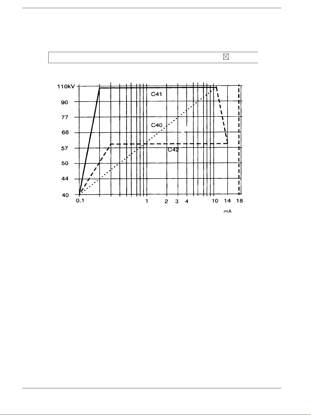
b) High Contrast Fluoroscopy
Prerequisite for this operating mode is a MEGALIX X-ray tube housing assembly with
circulation cooling.
Selection is made with the 2nd pressure point of a two-step footswitch
Selection of this mode of operation is displayed acoustically, with HC-gong
ig. 2
The curves shown in Fig. 2 are stored under the Numbers C40...C79.
Use of the Curves
C40: Antiisowatt curve
C41: Curve with low radiation exposure
C42: Curve with especially high contrast
Additional curves are stored as follows, but are not plotted for the sake of brevity.
C50: 40 kV / 0.1 mA, 55 kV / 0.4 mA, 85 kV / 14 mA, 110 kV / 9 mA
C60: 40 kV / 0.1 mA, 55 kV / 0.4 mA, 85 kV / 18 mA, 110 kV / 18 mA
C61: 40 kV / 0.1 mA, 110 kV / 18 mA
C62: 40 kV / 0.1 mA, 50 kV / 0.4 mA, 90 kV / 18 mA, 110 kV / 18 mA
C63: 40 kV / 0.1 mA, 50 kV / 0.4 mA, 80 kV / 18 mA, 110 kV / 18 mA
C64: 40 kV / 0.1 mA, 60 kV / 0.2 mA, 60 kV / 18 mA, 110 kV / 18 mA
C65: 40 kV / 0.1 mA, 110 kV / 0.2 mA, 110 kV / 18 mA
Dose rate is the same for Automatic 1 and Automatic 2 (Automatic 3).
POLYDOROS SX Register 4 RX63-050.034.12 TD AX 6 Siemens AG
Rev. 01 05.96 Medical Engineering
Page 37

Fluoro and Exposures Curves Chapter 4
Page 3 of 10
c) Therapy Simulation
• The OPTILIX 150/12/50C X-ray tube is used for the Therapy Simulation mode
(16 degree anode angle).
1000 W may be programmed as the max. fluoro power for this X- ray tube.
The same curves used as fluoro curves as for high contrast fluoroscopy.
Siemens AG TD AX 6 RX63-050.034.12 Register 4 POLYDOROS SX
Medical Engineering Rev. 01 05.96
Page 38

Chapter 4Fluoro and Exposures Curves
NOTICE
NOTICE
Page 4 of 10
Generating Your Own Fluoro Curves (Brief Description) 4
Curves C80...C99 are freely programmable for normal fluoro, for
high contrast fluoro and for therapy simulation.
• Select "System" / "Connect".
• Choose "Configuration" / "FC Curves..."
• Select "Data" / "Load" or "Backup..."
• Select fluoro curves: C80...C99 and edit them accordi ngly and conclude with "OK".
• Copy the data to the generator with "Data" / "Restore. ..".
• Allocate the fluoroscopy curves to the Automati c steps as appropriate (in
"Configuration" / "Unit sel ection" / "Button 1" / "FC-Details" / "Videomatic P")
• Select "Data" / "Restore"
• Select "System" / "Disconnect"
The fluoro curves can be printed out over "Data" / "Print".
POLYDOROS SX Register 4 RX63-050.034.12 TD AX 6 Siemens AG
Rev. 01 05.96 Medical Engineering
Page 39

Fluoro and Exposures Curves Chapter 4
NOTICE
Page 5 of 10
Final Recording of Fluoroscopy 4
The Test Certificate for "Fluoro and DFR/DR Systems", RXD0-000.037.01... is filed in
Register 9 of the System or Generator Binder.
Record the fluoroscopy parameters (dose rate values, fluoroscopy curves and the zoom
dose rate factors/zoom do se r ate) made at the customer’s locat ion for a ll Aut omati c step s
in the Test Certificate, Chapter 4.2
(from: "Configuration" / "Unit selection" / "Button 1..." / "FC-Details..." / "Videomatic P").
Preparations (Test Setup) 4
• Insert the 2.1 mm Precision copper filt er in the collimator.
• Set the SID
- Over-table units: 115 cm
- Under-table units: max. SID (Di stator not moved out)
- C-Arm units: 100 cm
• Select the I.I. full format.
• Move in the grid.
• Completely open the collimator.
Recording 4
• Switch on fluoro on the unit side.
• Record the kV and mA values that are adjusted for all automatic st eps and I.I.
formats in the Test Certificate, Chapter 4.2 (display on the generator console ).
The values entered in T a ble 4.2 of the Test Certificate can be used
for the check of the indirect dose rate in later service calls.
Siemens AG TD AX 6 RX63-050.034.12 Register 4 POLYDOROS SX
Medical Engineering Rev. 01 05.96
Page 40

Chapter 4Fluoro and Exposures Curves
Page 6 of 10
Exposure curves 4
General Remarks 4
The object thickness is determined during fl uoroscopy in the Polymatic. The exposure
parameters are determined on the basis of this value fo r direct and indirect technique:
Direct technique: Indirect technique:
• Exposure-kV • Exposure kV
• Density correctionr • Focus
• Exposure current
• Density correction
• Exposure time
Memory locations for 99 curves are available.
These memory locations are divided as follows:
• Curves C01...C79 are stored in the firmware.
-
Curve C00/C29 is a check curve for checking the transfer.
These characteristics must not be programmed for operation.
-
Under the numbers C01...C27, constant k V curves are stored in ascending order
(see table) at kV point intervals of 40 kV to 150 kV. They include: small focus,
auto focus, no density correction. As delta kV value, the difference to the next
higher kV value +1 kV is entered.
These curves are used for all indirect exposure t e chniques.
-
The numbers C31 to C57 include consta nt kV curves at kV-point interval s of 40.5
kV to 145 (see table).The other conditions correspond to curves C01..C27.
Characteristic curves
C01 . . . . . . . . . . . 40 kV C31 . . . . . . . . . . 40.5 kV
C02 . . . . . . . . . . . 41 kV C32 . . . . . . . . . . 41.5 kV
C03 . . . . . . . . . . . 42 kV C33 . . . . . . . . . . 43 kV
C04 . . . . . . . . . . . 44 kV C34 . . . . . . . . . . 45 kV
C05 . . . . . . . . . . . 46 kV C35 . . . . . . . . . . 47 kV
C06 . . . . . . . . . . . 48 kV C36 . . . . . . . . . . 49 kV
C07 . . . . . . . . . . . 50 kV C37 . . . . . . . . . . 51 kV
C08 . . . . . . . . . . . 52 kV C38 . . . . . . . . . . 53.5 kV
C09 . . . . . . . . . . . 55 kV C39 . . . . . . . . . . 56 kV
C10 . . . . . . . . . . . 57 kV C40 . . . . . . . . . . 58.5 kV
C11 . . . . . . . . . . . 60 kV C41 . . . . . . . . . . 61.5 kV
C12 . . . . . . . . . . . 63 kV C42 . . . . . . . . . . 64.5 kV
C13 . . . . . . . . . . . 66 kV C43 . . . . . . . . . . 68 kV
C14 . . . . . . . . . . . 70 kV C44 . . . . . . . . . . 71.5 kv
C15 . . . . . . . . . . . 73 kV C45 . . . . . . . . . . 75 kV
C16 . . . . . . . . . . . 77 kV C46 . . . . . . . . . . 79 kV
C17 . . . . . . . . . . . 81 kV C47 . . . . . . . . . . 83 kV
C18 . . . . . . . . . . . 85 kV C48 . . . . . . . . . . 87.5 kV
C19 . . . . . . . . . . . 90 kV C49 . . . . . . . . . . 93 kV
C20 . . . . . . . . . . . 96 kV C50 . . . . . . . . . . 99 kV
C21 . . . . . . . . . . . 102 kV C51 . . . . . . . . . . 105 kV
C22 . . . . . . . . . . . 109 kV C52 . . . . . . . . . . 113 kV
C23 . . . . . . . . . . . 117 kV C53 . . . . . . . . . . 121 kV
C24 . . . . . . . . . . . 125 kV C54 . . . . . . . . . . 129 kV
C25 . . . . . . . . . . . 133 kV C55 . . . . . . . . . . 137 kV
C26 . . . . . . . . . . . 141 kV C56 . . . . . . . . . . 145 kV
C27 . . . . . . . . . . . 150 kV
POLYDOROS SX Register 4 RX63-050.034.12 TD AX 6 Siemens AG
Rev. 01 05.96 Medical Engineering
Page 41

Fluoro and Exposures Curves Chapter 4
Page 7 of 10
C60:
C61:
C62:
C63:
The following curves arerogrammed for various medical applications:
Gastrointestinal tract I 85...125 kV
Thorax 66...125 kV
Gastrointestinal tract II 70...109 kV
Gall bladder/kidney 60...70 kV
Siemens AG TD AX 6 RX63-050.034.12 Register 4 POLYDOROS SX
Medical Engineering Rev. 01 05.96
Page 42

Chapter 4Fluoro and Exposures Curves
NOTICE
Page 8 of 10
Generating Your Own Curves 4
• The numbers 80 to 99 are reserved for curves which can be programmed fr eely as
requested by the customer.
It is possible to use existing curve s unchanged or to program separate curves.
Generation of the customer-specifi c curves is described below. Select "System" /
"Connect".
• Select "Configuration" / "EXP-Curves..."
• Select "Data" / "Load" or "Backup..."
• Select exposure curves: C80...C99 and edit them accord ingly and exit with "OK".
• Copy the data to the generator with "Data" / "Restore. ..".
• Select "System" / "Disconnect"
The exposure curves can be printed out over "Data" / "Print".
POLYDOROS SX Register 4 RX63-050.034.12 TD AX 6 Siemens AG
Rev. 01 05.96 Medical Engineering
Page 43

Fluoro and Exposures Curves Chapter 4
Page 9 of 10
Allocating the Exposure Curves to the Organ Keys 4
Use the following procedure to allocate the curves
(see also the POLYDOROS SX 50/80 Operating Instructions).
• Select the program menu and press the lock key.
• Select the exposure technique at the unit (direct technique or Sircam)
• Press the particular organ key.
• Switch "0-Point Technique" on.
• Select the desired acquisition curve i n the report line using the +/- key s.
• If the focus or autofocus contained in the curve is not to be used, then select t he desired
focus (if both LEDs light up, Aut ofocus is selected).
• If needed, enter additional densi ty correction with the key
• Save the configuration by pressing "SAVE".
• Use the lock key to switch off the programming uni t.
Siemens AG TD AX 6 RX63-050.034.12 Register 4 POLYDOROS SX
Medical Engineering Rev. 01 05.96
Page 44

Chapter 4Fluoro and Exposures Curves
Page 10 of 10
This page intentionally left blank.
POLYDOROS SX Register 4 RX63-050.034.12 TD AX 6 Siemens AG
Rev. 01 05.96 Medical Engineering
Page 45

NOTICE
Final works 5
Options 5
• Select "Configuration"/"Options "
• Is the default organ program (and default expo sure system) selected when generator is
"ON"?
• Adjustment of the patient profile is reset when there is a change of the organ prog ram.
• With the direct technique: 0-Point Techni que can be switched on with the organ change
and 0-Point key
Can be switched on only with the 0-Point key
• With SIRCAM: 0-Point Technique can be switched on with organ change and
0-Point key
Can be switched on only with the 0-Point key
• With the 0-Point Technique without fluor oscopy, no exposure data available (exposur e
blocking)! Take the exposure data f rom the average water value (nominal value) of the
exposure curve.
• Enter the dose/dose rate value in µR/ µRs or in nGy/ nGy/s
• With "Data" / "Store" store the programm set tings
Chapter 5
Page 1 of 2
Additional information about the options can always be obtained
by selecting "Help" / "Index" under "The Service Software Menu" /
"Configuration".
Siemens AG TD AX 6 RX63-050.034.12 Register 4 POLYDOROS SX
Medical Engineering Rev. 01 05.96
Page 46

Chapter 5Final works
NOTICE
Page 2 of 2
Important: Saving the Programming 5
After completing the start-up, it is extremely important to save the programming.
There must be "four" system-specific files in the directory on Diskette 3- of the generator
service software (with software VE00A e.g.: "a:\pl_sx\ve00a\backup") or these files must
be created.
- "kundexyz.210" - system configurat ion ("Configuration"), adjustm ents ("Adjustment")
and organ program data;
the save is made in the main menu
"Data" / "Change Host..." / " Backup Data"
- "kundexyz.alp" - system confi guration ("Configuration")
the save is made in the main menu
"Data" / "Backup";
"Data" / "Save..."
- "kundexyz.cpr" - organ program names
the save is made in the main menu
"Configuration" / "Organ Programs" / "Backup names ..."
- "kundexyz.opr" - organ program data
the save is made in the main menu
"Configuration" / "Organ Programs" / "Backup data ..."
When doing this, observe the following:
- The file name "kundexyz" is composed of a maxi mum of 8 freely selectable letters or
numbers,
e.g. the name of the customer or the Serial Number of the generator:
"dr-test.210"; "0 1834.alp"
- The extensions (extension of the file name):
".210"; ".alp"; ".o pr"; ".cpr" may not be changed!
- File name and extension must be separated by a deci mal point!
- The ability to enter addit ional information should be used fu lly when saving
(succeeding colleagues will be grateful for this!);
e.g.: "17.Feb.1995;Start -up.;IQ;Sch"
With FLUOROSPOT mode, the exposure data for this operating
mode is sto red in the FLUOROSPOT.
POLYDOROS SX Register 4 RX63-050.034.12 TD AX 6 Siemens AG
Rev. 01 05.96 Medical Engineering
Page 47

NOTICE
Appendix, SDM Service 6
Description 6
SDM (Selective Dominant Measuring) descr ibe s a system to detect the output bri ghtnes s
of the image intensifier for all indirect technique modes (fluoroscopy, DSA, DFR). The
detector is a PDA (Photo Diode Array). It is used as the detector system, which basically
takes over the function of the photo multi plier.
The PDA is comprised of individual semiconductor segments which are combined into
ADR measuring fields. The measuring fields are can be selected parallel, comparable to
Iontomat measuring fields . Se lecti on of a c ircul ar measuring fi eld i s also p ossi ble, bu t t his
cannot be combined with the other fields.
The size of the measuring fields is switched automatically depending on the zoom format.
Checking the PDA Size 6
Prerequisites 6
The television system and the DFR system, if confi gured, must be operational.
The television camera must be centered on the image intensifier.
• Switch SS OFF in the generator.
Chapter 6
Page 1 of 4
• Move the unit into a convenient position so that ho using on the I.I. attachment can be
removed easily. If possible, remove the paneling screws now.
• In systems configured with DFR, mark the position of the brightness and contrast
settings on the monitor and releas e the lock on the adjustment potentio meters.
• At the unit, leave fluoroscopy switched on for the following steps (for this, it may be
necessary to secure the fluoro switc h in place).
• Remove the housing from the I.I. attachment.
• Switch S1 on the D100 to "Service" (Fig.2); the PDA will be illuminated.
After approx. 4 minutes, the i llumination for the PDA switches off
automatically. To switch the light back on, the S1 on the D100
must be switched back briefly to "Normal".
76 mm applicable only for
the 40 HDR I.I.
Fig. 1
Siemens AG TD AX 6 RX63-050.034.12 Register 4 POLYDOROS SX
Medical Engineering Rev. 01 05.96
Fig. 2
Page 48

Chapter 6Appendix, SDM Service
Page 2 of 4
• Turn the brightness and contrast control s on the monitor until the PDA is clearly vi sible.
With DFR systems, store the LIH image if needed and c hange the windowing or edge
enhancement.
• Measure the size of the PDA as shown in Fig.1 and compare the value wit h that in the
Table.
In case of deviations procede with the section "Adjust ting the Size of the PDA".
PDA measured at SIMOMED H - 44 cm 6
40 cm I.I. 33 cm I.I. 23 cm I.I. Urology 40cm I.I. Urology 33cm I.I.
PDA size in mm 76 91 116 76 91
Tolerance in mm + / -7 + / -9 + / -11 + / -7 + / -9
• Switch Fluor o OFF at the unit.
• On the D100,set S1 back to "Normal".
• Install the cap on the I.I. attachment.
• Switch the SS ON at the generator.
• In systems with DFR, set the brightness and contrast controls on the monitor back to the
marked position and lock the controls in place.
Adjusting the Size of the PDA 6
• As described in the previous paragraph, make the PDA visi ble on the monitor.
• Loosen the two Allen-head set screws on the PDA lens.
• Adjust the size of the PDA for the particular I .I. (see above table) by turning the len s
(plastic ring).
• Retighten the Allen-head set screws.
• Switch Fluor o OFF at the unit.
• On the D100, set the S1 back to "Normal".
• Install the housing on the I.I. atta chment.
• Switch SS ON at the gener ator.
Checking the Selected ADC Meas uring Field 6
The dose rate must be adjusted as described in the chapter: "Adjustment" / "Dose
Rate"
• Select left, rectangular measuring fi eld at the unit control console .
• Switch Fluor o ON at the unit.
• In systems configured with the universal collim ator, move the DSA finger over the ADC
measuring field (with Fluorospot H the measur ing field is displayed on the monito r).
In systems configured with the coll imator without the DSA finger, place 2.1 mm Cu on
the tabletop and move over the measuring field.
POLYDOROS SX Register 4 RX63-050.034.12 TD AX 6 Siemens AG
Rev. 01 05.96 Medical Engineering
Page 49
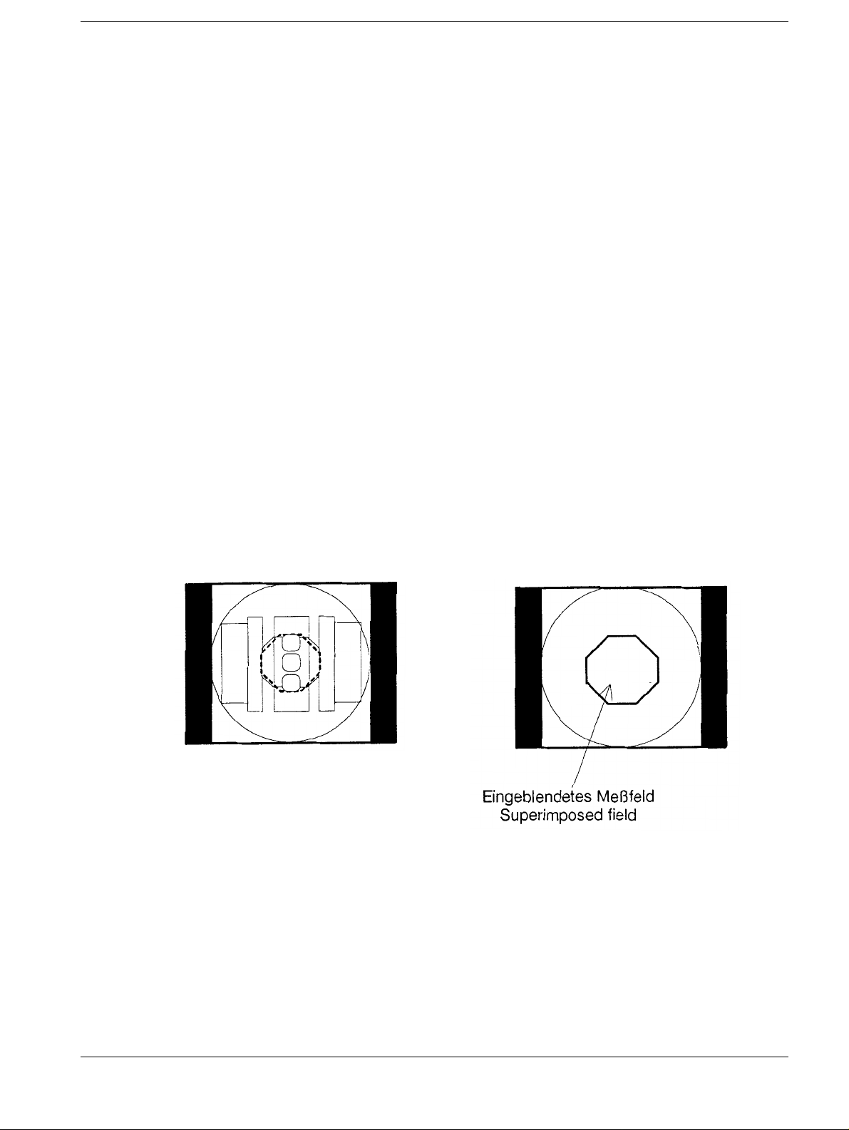
Appendix, SDM Service Chapter 6
Page 3 of 4
• At the generator control console, flu oro kV and fluoro mA must increase according t o the
particular fluoro curve.
• Repeat the test using the measuring field on the ri ght.
• Switch Fluoro OFF.
Checking the Superimposed ADC Measuring Field with
FLUROSPOT H
• Select I.I. full format and the round measuri ng field at unit.
• Make the PDA visible as described in the paragraph "Checki ng the PDA Size".
• Mark the width and center of the octagonal measur ing field on the monitor (Fig.3).
• At the unit, switch Fluoro ON.
The measuring field will be superimpose d on the monitor by the FLUOROSPOT H for as
long as was configured for the FLUORSPOT H in the system conf iguration.
If the display time is not suf ficient, it can be extended using t he special function "System
Adjustments".
6
• The width and position of the field must be identi cal with the mark. Permissible
misalignment of size and position i s 1 cm each (Fig.3).
• To change the size of the superimposed field, sel ect the Fluorospot H system
configuration, Mask 6, "Measurement fi eld scale factor".
It is not possible to change the location of the superimposed field (Fig.4).
Siemens AG TD AX 6 RX63-050.034.12 Register 4 POLYDOROS SX
Medical Engineering Rev. 01 05.96
Page 50

Chapter 6Appendix, SDM Service
Page 4 of 4
Measurement field sizes in zoom mode (RX unit with 40-4 HDR
I.I.)
(I.I. diameter:
(I.I. diameter
(I.I. diameter
6
(I.I. diameter
TD AX 6 / Scheuermeyer
TD AX 7 / Seel
TD AX 1 / Biedermann, Tropia
POLYDOROS SX Register 4 RX63-050.034.12 TD AX 6 Siemens AG
Rev. 01 05.96 Medical Engineering
 Loading...