

Page 1
(without price)
INDEX
Wireless Pocket PC
SIEMENS SX45/SX45G
(JX-700A/702A)
SEP. 2001
Revised Version: Oct. 2001
R
Page 2

CONTENTS
1. SPECIFICATIONS -----------------------------------------------------------------------------------------1
■ Accessories ------------------------------------------------------------------------------------------- 3
2. GENERAL GUIDE -----------------------------------------------------------------------------------------4
3. RESET OPERATION--------------------------------------------------------------------------------------6
4. DATA COMMUNICATIONS---------------------------------------------------------------------------- 10
4-1. General ------------------------------------------------------------------------------------------------ 10
4-2. Connection to PC ---------------------------------------------------------------------------------- 10
4-3. Data Backup ----------------------------------------------------------------------------------------- 10
4-4. Infrared Communication ------------------------------------------------------------------------ 11
5. ADJUSTMENT-------------------------------------------------------------------------------------------- 12
5-1. Setting (Adjusting) DC Voltage to AD converter ---------------------------------------- 12
5-2. Display adjustment-------------------------------------------------------------------------------- 14
6. OPERATION CHECK ----------------------------------------------------------------------------------- 15
6-1. Preparation------------------------------------------------------------------------------------------- 15
6-2. How to install the diagnostic program ----------------------------------------------------- 15
6-3. Operation Check ----------------------------------------------------------------------------------- 18
6-4. Operation check for diagnostic program DKP700 -------------------------------------- 25
7. TROUBLE SHOOTING--------------------------------------------------------------------------------- 36
7-1. Function/Operation troubles for PDA/GSM ----------------------------------------------- 36
7-2. Hard trouble for PDA/GSM---------------------------------------------------------------------- 36
8. CIRCUIT BLOCK DIAGRAM ------------------------------------------------------------------------- 39
9. WIRING DIAGRAM-------------------------------------------------------------------------------------- 40
10. SCHEMATIC DIAGRAMS ----------------------------------------------------------------------------- 41
10-1. MAIN BLOCK ---------------------------------------------------------------------------------------- 41
10-2. POWER BLOCK ------------------------------------------------------------------------------------ 42
10-3. AUDIO BLOCK -------------------------------------------------------------------------------------- 43
10-4. REF BLOCK ------------------------------------------------------------------------------------------ 44
10-5. CARD BLOCK --------------------------------------------------------------------------------------- 45
10-6. KEY BLOCK------------------------------------------------------------------------------------------ 46
10-7. FROM BOARD BLOCK --------------------------------------------------------------------------- 47
10-8. INDICATOR BLOCK ------------------------------------------------------------------------------- 48
10-9. CRADLE BLOCK ----------------------------------------------------------------------------------- 49
11. PCB VIEW ------------------------------------------------------------------------------------------------- 50
12. DISASSEMBLY PROCEDURE----------------------------------------------------------------------- 55
13. ASSEMBLY PROCEDURE---------------------------------------------------------------------------- 62
14. DIAGNOSIS FLOW CHART -------------------------------------------------------------------------- 66
15. TOOL LIST------------------------------------------------------------------------------------------------- 68
16. PARTS LIST ----------------------------------------------------------------------------------------------- 69
17. EXPLODED VIEW --------------------------------------------------------------------------------------- 72
Page 3

IMPORTANT!!
1. Main Battery Warning:
• Replace the main battery with Type V30145-K1310-X217-1.
Use of another battery may present a risk of fire or explosion.
• This battery pack is suitable for use only with Wireless Pocket PC model SX45.
• Dispose of used battery according to the manufacturer's instructions.
2. Back-up Battery Warning:
• Replace only with Matsushita's CR2032 or equivalent type recommended by the manufacturer.
• Danger of explosion if battery is incorrectly replaced.
• Dispose of used batteries according to the manufacturer's instructions.
3. Fuse Replacement
• Replace only with original fuse F201 and F202 on Main PCB, fuse F1 on inverter PCB. The specification
of original parts and the replacement instructions as follows:
Item Specification
F201 F0805B3R00FWTRM
F202 F0603C1R00FWTRM
Refer to the PCB view of J700-1 PCB (Bottom view).
Item Specification
F1 KMC03
Replece with whole inverter unit (Spec. INV-J700-S) including above fuse F1 part due to the availability.
Refer to the PCB view of Inverter unit.
Causion: Another fuse may create danger
4. Main Battery Set during Operation
As long as during operation, the main battery should be set with the unit in any time.
Otherwise the unit will not turn on without main battery.
Page 4

1. SPECIFICATIONS
Display: 240 × 320 pixels
TFT colour LCD (65,536 colours)
CPU: VR4122
Memory: 32 MB
Interfaces: Serial: RS-232C, 115.2 kbps max.
Infrared: Meets IrDA Standard (Level 1.1)
Range: between 5 cm an 30 cm.
USB (client)
GSM: class B
upstream 14.4 kbps
downstream64 kbps
Card slot: CompactFlash card, 3.3V Type I / Type II
SD card/MultiMediaCard TM (only SPI-Mode)
Headset jack: Use for connection of the headset only.
Dimension: 135(W) × 87(D) × 27(H) mm
Weight: Approximately 300 g
Power supply
Main: Rechargeable battery pack 3.7 V DC
(lithium ion battery, L36880-N9001-A106)
AC adapter 100-240 V, 50/60 Hz (L36880-N9001-A108)
Backup: CR2032 lithium battery
Approximate battery life (normal temperature and minimal display intensity)
Main: (actual time may be shorter due to conditions when charging.)
8 hours: Continuous input and data display at a ratio of 1:10,
with screen brightness at lowest possible level.
150 hours: Standby (GSM switch in ON position.)
ca. 3 hours: Continuous communication
Even when the unit is turned off, small amount of power is required
to retain memory contents, etc. This means that battery power is
consumed even when you do not use the unit.
The actual amount of operation time that can be expected from
batteries depends on operating conditions, settings and other
variables.
Backup: 5 years: Main battery is charged or replaced immediately after
appearance of message to replace main battery.
5 days: No battery replacement after appearance of message
to replace main battery.
Approximate charge time (normal temperature)
7 hours: Charge time is longer for the first charges after
purchasing the unit or installing a new battery pack.
Operating temperature: 0 °C to 40 °C
Charging temperature: 10 °C to 35 °C
Caution Danger of explosion if battery is incorrectly replaced.
Replace only with the same or equivalent type recommended by the manufacturer.
Dispose of used batteries according to the manufacturer’s instructions.
— 1 —
Page 5
Current consumption:
Note:
1. When measuring these current, it is recommended to use the analog ammeter to make the measurement
easier due to protecting the ammeter from noises.
2. Make LCD display contrast suitable (default) condition before measurement.
3. Measure under the ambient temperature range 15˚C~35˚C
Operation Mode Input Voltage Current Consumption
Main Menu of OPERATION Rechargeable Battery : ≤180 mA (Power ON and
CHECK in this manual 4.0 ± 0.1 V no operation)
*POWER CONTROL of Rechargeable Battery : ≤380 mA (Power ON and
OPERATION CHECK 4.0 ± 0.1 V operation)
*POWER CONTROL of AC Adapter : 5.9 V ± 0.1 V ≤320 mA
OPERATION CHECK
Power/OFF Rechargeable Battery : ≤4.0 mA (Power OFF and
4.0 ± 0.1 V no operation)
Power/OFF Lithium battery for back-up ≤1.7 mA
3.0 ± 0.1 V
*Tapping 5 POWER CONTROL in the OPERATION CHECK Main Menu screen display, the following display
will appear.
Currently CPU clock : 150 MHz
VT Clock : 50 MHz
Push Action key to exit
Voltage detection:
Main (Rechargeable) Battery:
* Tapping 2 SWITCH in the OPERATION CHECK Main Menu screen, the following display will appear.
VDET Main voltage Display
0, 1
2
3.90 V OFF
3.55 V ON
3.90 V OFF
3.20 V ON
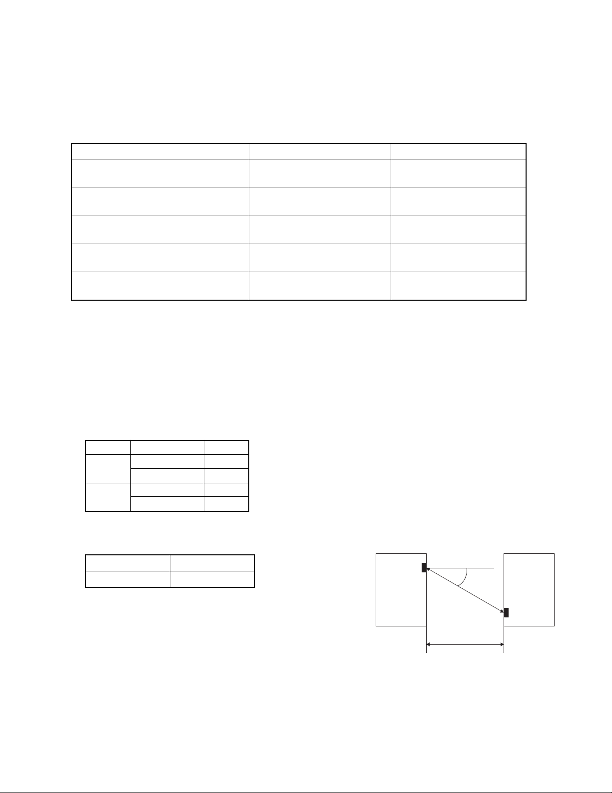
Unit Alignment Condition for data transfer using IrDA :
Length (L) Angle (A)
L ≤ 30 cm A ≤ 15˚
A
L
SX45SX45
— 2 —
Page 6
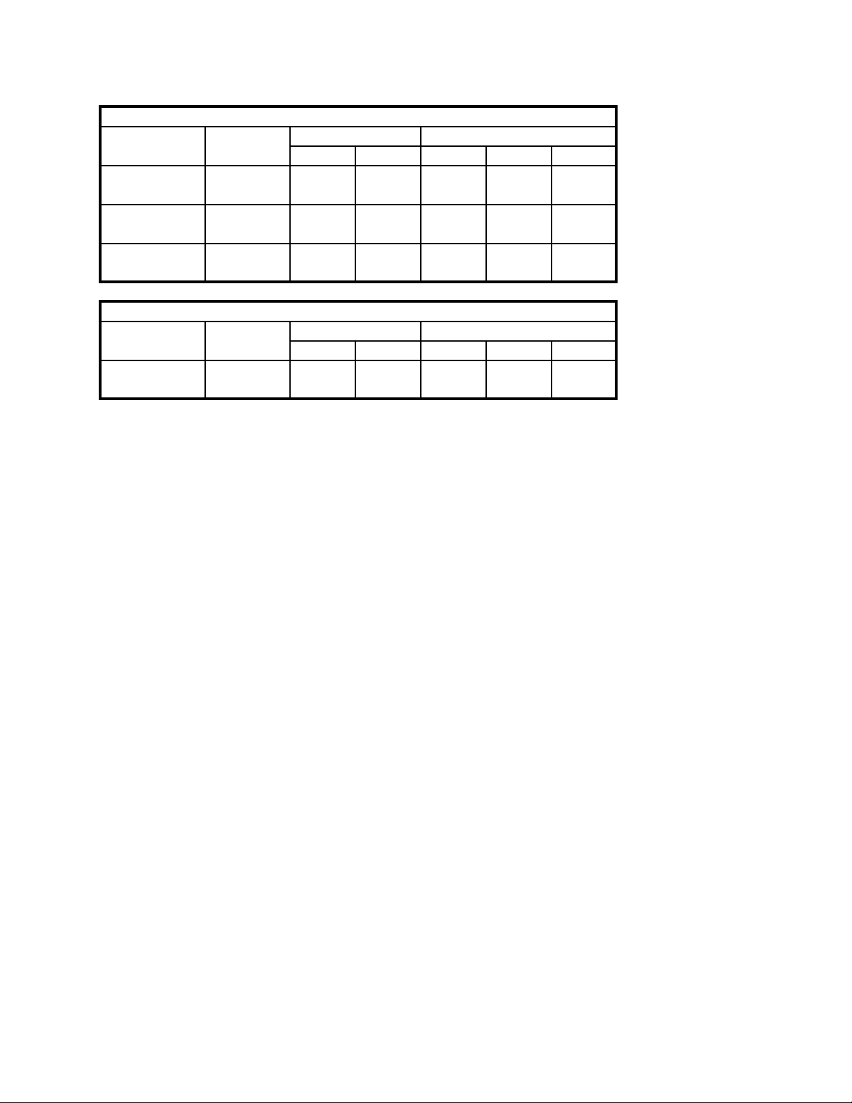
ROM check value :
English Version
Check SUM BUS Check
Production Build No. ROM1 ROM2 ROM1 ROM2
1~ High 0c98 0d10
1900unit 7139 dd20 332f Low 14ab 151d
1901~ High 0c98 0d10
3900unit 7141 9cd1 f88a Low 1656 158e
3900unit~ High 0c98 0d10
7144 f4ab 31aa Low 1472 15be
German Version
Check SUM BUS Check
Production Build No. ROM1 ROM2 ROM1 ROM2
1unit~ High 0c9b 0dd1
7144 ad0d 2a58 Low 165a 1668
NOTE: Build No. can be read by bottom of display when “CONTRAST” setting menu.
Check Sum, Bus Check value can be read by Main Menu of OPERATION CHECK. (refer to the
chaptor)
Build No., Check Sum, Bus Check value may be changed without notice.
■ Accessories
The following accessories can be supplied from Siemens sales.
1. Sync-Station L36880-N9001-A103
2. Pocket PC serial cable L36880-N9001-A104
3. SX45 USB cable L36880-N9001-A105
4. Recargeable battery pack L36880-N9001-A106
5. AC adaptor L36880-N9001-A108
— 3 —
Page 7
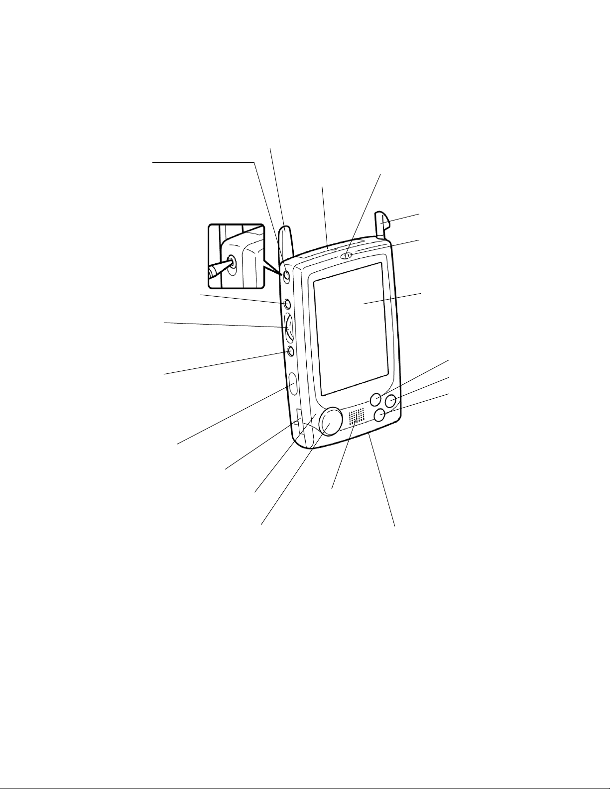
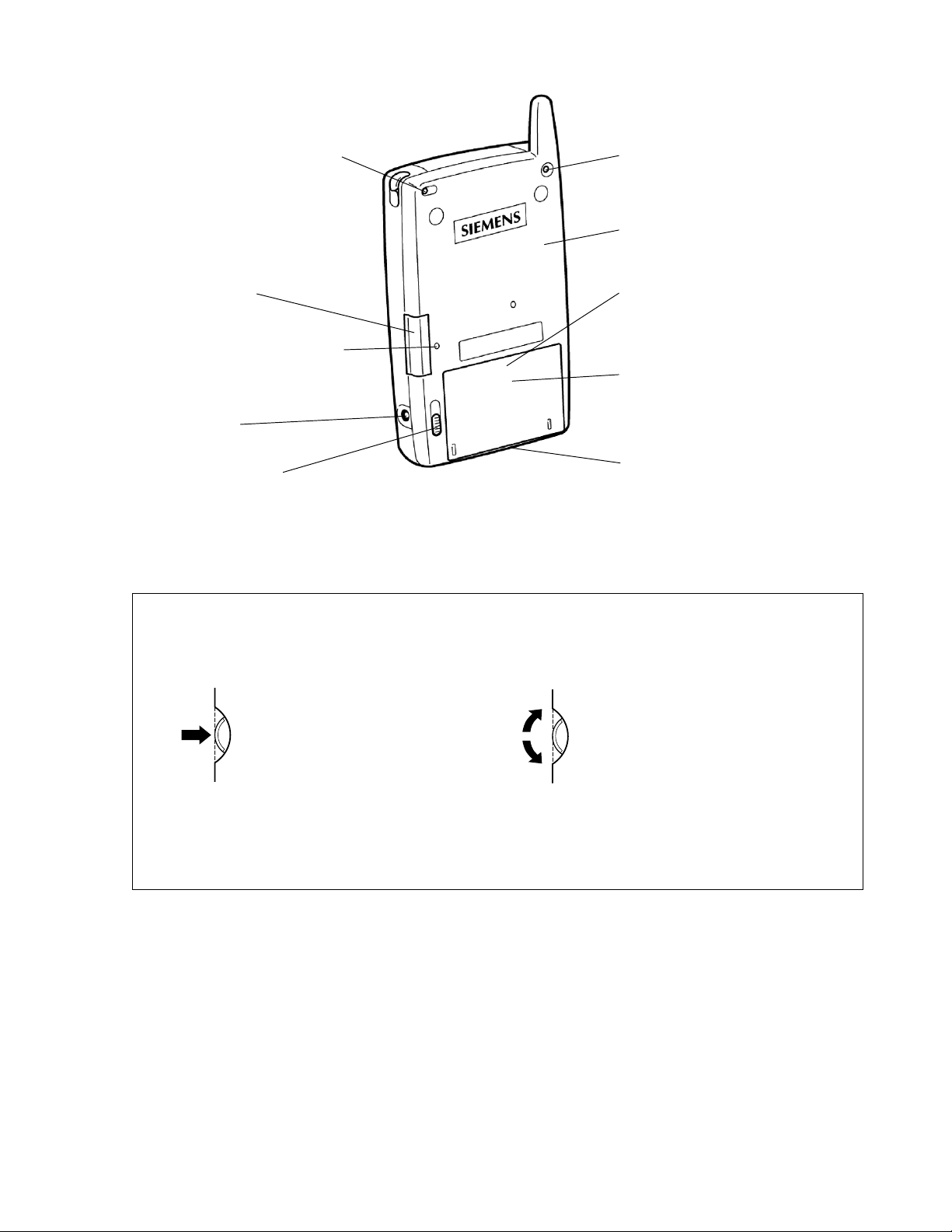
2. GENERAL GUIDE
GSM switch
Slide to the ON position
to enable the mobile
module and to OFF to
disable.
Use the stylus to
operate the switch.
Power button
Turns power on and off.
Action control
See “About the [Action]
control” on the next page.
Record button
(Programe button)
Voice memo recording is
activated as long as you
press this button.
Infrared port
Backup battery tray
Antenna
CompactFlash
card slot
Charge indicator (Red/Green)
Lights red when the battery pack is
charging and turns green when full
charge is achieved.
Stylus
Indicator lamp (Red)
Alerts you to alarms and
warning.
Touch screen
Perform operations and
input data by tapping and
writing directly on the
screen.
• QuickAccess
• Contacts
• Calendar
Program buttons
Press to launch the
assigned program.
The programs shown
here are the initial
default settings.
Microphone
Cursor button
Moves the cursor around
the screen.
Speaker
Headset jack
Connect the headset here.
— 4 —
Page 8
CompactFlash card lock switch
If the inserted card has a lock, this
switch locks the card in place so it
does not come out accidentally.
External antenna jack
Reset button
SD/MMC card slot
SIM card slot
(inside battery compartment)
Press the stylus into the hole
to open SD/MMC card slot.
Main battery
(Rechargeable battery pack)
AC adapter jack
Main battery lock key
Serial connector
For connection of the SyncStation, the SX45 USB cable, or
the RS-232C cable.
About the [Action] Control
Operations can be performed by pressing and rotating the [Action] control button.
Pressing the [Action] control
button performs an operation
similar to the Enter key of a
computer keyboard.
Rotating the [Action] control
button performs operations similar
to the up and down arrow keys
of a computer keyboard.
See SX45 online help for information about using the [Action] control button with each application.
The text in the online help indicates an [Action] control press operation as “Action,” and an [Action]
control rotate operation as “Up/Down control.”
— 5 —
Page 9

3. RESET OPERATION
Batteries
Your Pocket PC is powered by a dual power supply that consists of a main battery (rechargeable battery pack)
and a backup battery (CR2032 lithium battery).
• We recommend that you use the Power Properties to keep informed about the current levels of your main
and backup batteries. See the separate Pocket PC User’s Guide and Pocket PC online help for more
information about these properties.
Important
The following messages appear whenever the battery power drops below a certain level.
Main battery
Recharge the battery pack (L36880-N9001-A106) as soon as possible after the following message appears.
“Main Batteries Very Low
To prevent possible data loss, replace or recharge your main batteries according to the owner’s manual.”
Backup battery
Replace the backup battery as soon as possible after the following message appears.
“Backup Battery Very Low
To prevent possible data loss, replace or recharge your backup batteries according to the owner’s
manual.”
If the unit switches off due to insufficient power , the following warning message appears on the display the next
time you switch on the unit.
“Warning
Due to high current demand by the hardware, the system powered down in order to protect memory
contents...”
If the unit switches off due to a sudden power drain by a CompactFlash card, the following warning message
appears on the display the next time you switch on the unit.
“Warning
Due to high current demand by the card, the system powered down in order to protect memory
contents...”
Important
Make sure that you observe the following important battery handling precautions. Failure to do so can cause
batteries to leak. This can result in damage to surrounding items and may result in fire and electrical shock.
• Always make sure that the positive (+) and negative (–) poles of the batteries are aligned correctly.
• Use only the types of batteries specified for use with this unit (L36880-N9001-A106).
• Charge the battery pack in an area where the temperature is between 10 °C and 35 °C. Charging in areas
that are very cold or exposed to direct sunlight can cause deterioration and leaking of the battery pack.
• To avoid deterioration and leaking, the battery pack is designed to discharge even when you do not use the
Pocket PC. Make sure that you recharge the battery pack at least once every three months, regardless of
how much you use the Pocket PC during that time.
• A battery pack that loses power too quickly after it is charged is probably near the end of its service life. If this
is the case, you must purchase a new battery pack.
— 6 —
Page 10

Replacing the main battery
1. Make sure that your Pocket PC is turned off.
2. Turn the Pocket PC over.
3. The main battery lock to the FREE position.
4. Insert a new battery pack into the battery compartment.
5. The main battery lock to the LOCK position.
Replacing the backup battery
Important
• Never remove the main battery and backup battery from the Pocket PC at the same time. Doing so causes
all data stored in memory to be deleted.
• Should the main battery and the backup battery both require replacement, always replace the main battery
first.
• Make sure that you replace the backup battery as soon as possible whenever the following message appears
on the display:
“Backup Battery Very Low
T o prevent possible data loss, replace or recharge your backup battery according to the owner’s manual”.
1. Make sure that your Pocket PC is turned off.
2. Turn the Pocket PC over.
3. Insert the tip of the stylus under the backup tray, and pull the tray out.
4. Remove the old battery.
5. After wiping both sides of a new lithium battery (CR2032) with a dry cloth, place it into the backup battery
tray with the positive side facing up.
6. Replace the backup tray holder into the Pocket PC.
Resetting the unit
“Reset” is similar to a computer reboot. Performing a reset deletes any data that is in the process of being input
or edited, without yet being saved. Data stored in memory, however, is retained, as are all settings.
Perform the reset operation whenever the unit fails to operate correctly due to operational error or some other
abnormality. Any of the following symptoms indicate that a reset is required.
• The unit does not respond when you tap the screen or press a button.
• The icon that indicates that a procedure is in progress remains on the display for a long time.
Important
We strongly recommend that you back up the data in Pocket PC memory, if possible, before performing a
reset. Normally the reboot-type reset does not delete data in Pocket PC memory. If corrupted data is discovered,
however, all data stored in memory will be deleted.
No matter what type of computing device you are using, it is always a good idea to back up memory contents
periodically to protect against unexpected loss of data.
— 7 —
Page 11

Performing a reset
1. Use the stylus to press the RESET button.
• The unit performs a reset followed by a memory check operation.
If no data error is found, the following two screens appear on the display in succession.
• Startup screen
• Today screen
2. Normal unit operation is possible after the desktop appears.
• Memory data and settings are retained when you reset the Pocket PC.
Important
If the above operation does not solve the problem, perform a full reset.
Memory error message
If the memory check operation that the unit performs when the RESET button is pressed detects a data error,
the following message appears on the screen instead of the startup screen.
“A problem with memory contents has been found. Press [ Action] to continue with the reset procedure,
which restores normal system operation.
Note that if the system determines that user memory cannot be repaired, it will delete all user data
cuttently in memory.
See the User’s Guide for details about initializing memory.”
This message indicates that the memory error is fatal and so recovery is impossible. Press the [Action] control
to execute a full reset (memory initialize), which deletes all data stored in memory.
• Pressing the [Action] control should display the Startup screen followed by the touch screen calibration
screen. The remainder of this procedure identical to the initial setup described in the Quick Start Guide.
Perform the steps of the initial setup procedure.
• If pressing the [Action] control returns to the desktop without displaying the startup screen first, see the
following explanation for the procedure you need to follow.
What to do if the startup screen does not appear when you press the [Action] control
Even though the desktop appears when you press the [Action] control, there is still a data error in memory and
you have to perform a full reset (memory initialize). Before you do, however, there is the chance that some of
the data in memory can be recalled and even transferred to a computer. Try recalling the data you need before
following the procedure described on the next page to perform a full reset.
Important
Do not use the ActiveSync backup function to back up data to a computer when you suspect a data error. Doing
so may also include the corrupted data that is causing your problem, which means the problem will reappear
when you restore the data.
Full reset (memory initialize)
Full reset (memory initialize) deletes all data, and resets all unit parameters to their initial defaults.
You should perform a full reset under the following conditions.
• When you want to delete all memory data and return unit settings to their factory defaults
• When you forget your password and need to clear it
• When a data error causes operational problems
• Appearance of the message: “A problem with memory contents has been found...”
— 8 —
Page 12

Performing a full reset
Important
• The following procedure deletes all data in memory. Ensure that data is backed up or that you no longer
need it before performing the following procedure.
• If there is a CompactFlash card and SD card/MultiMediaCard in the Pocket PC’s slot, remove the card
before performing the full reset.
1. Make sure that the unit’s power is turned on.
2. While holding down the [Power] button, use the stylus to hold down the RESET button for about two seconds.
• This causes the following message to appear on the display screen.
“Proceeding with this operation initializes memory. Press [Action] to proceed or [Record] to cancel.”
3. Press the [Action] control.
• This causes the following message to appear on the display screen.
“Proceeding with this operation deletes all data stored in memory . Press [Action] to proceed or [Record]
to cancel.”
4. Press the [Action] control again.
• This starts the full reset operation, which deletes all data in memory.
• Pressing the [Action] control displays the Startup screen. The remainder of this procedure is identical to the
initial setup described in the Quick Start Guide. Perform the steps of the initial setup procedure.
You can abort the full reset operation while the messages in steps 2 and 3 are on the display by pressing the
[Record] button.
Errors following a full reset
Either of the following two conditions can cause errors to continue, even after you perform a full reset.
• Hardware defect
• System problem caused because you failed to perform the reset procedure correctly before using the unit
for the first time
— 9 —
Page 13

4. DATA COMMUNICATIONS
4-1. General
Performing Initial Setup and FULL RESET, data saved in the unit will be deleted.
Performing MEMORY BACKUP/RESTORE and CARD BACKUP TOOL Operations descibed in this Chapter,
save these data to PC and CF card before performing Initial Setup and FULL RESET.
1. Between PC and SX45 using Activesync 3.1 software
2. Between CF card and SX45
3. Between two units using IrDA
4. Between notebook-sized PC and SX45 using IrDA ports
Refer to UNPACKING and GENERAL GUIDE in this manual concerning these communications.
4-2. Connection to PC
Required System Configuration
The minimum system configuration required for running ActiveSync ® 3.1 is described in the manual of User
Guide of Pocket PC.
4-3. Data Backup
There are two types of data back up; ActiveSync ® 3.1 and Card Backup Tool.
■ BACKUP/RESTORE using ActiveSync 3.1
Refer to HELP for ActiveSync 3.1 for details.
■ Card Backup Tool
Refer to Card Backup Tool User’s guide for details.
— 10 —
Page 14
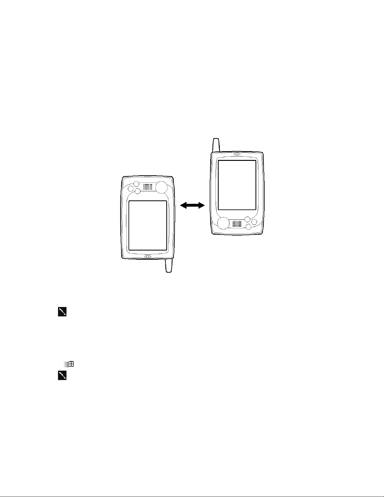
4-4. Infrared Communication
Transfer Items Using Infrared
Using infrared (IR), you can send and receive information, such as contacts and appointments, between two
Windows-powered Pocket PCs.
To send information
1. Switch to the program where you created the item you want to send and locate the item in the list. If you
want to send more than one item, drag the stylus across the items you want to send.
2. Align the IR ports so that they are unobstructed and within a close range.
• The two infrared ports should be within about 30cm from each other.
3. Tap and hold the item, and tap Send via Infrared on the pop-up menu.
You can also send items, but not folders, from File Explorer. Tap and hold the item you
want to send, and then tap Send via Infrared on the pop-up menu.
To receive information
1. Align the IR ports so that they are unobstructed and within a close range.
2. Tap , Programs, and then Infrared Receive.
You can also receive items from Tasks, Contacts, Calendar, and Notes by tapping Tools
and then Receive via Infrared in list view.
— 11 —
Page 15
5. ADJUSTMENT
5-1. Setting (Adjusting) DC Voltage to AD converter
The following operation are not only for Check, but also for setting (adjusting) for DC voltage to AD converter in
CPU.
When calibration for touch panel, battery voltage detection and so on are not correctly performed, try to check
and perform these settings (adjustments).
Prepare one (or two) DC voltage stabilizers for Main/Sub battery power supply.
Important
These settings (adjustments) for the main PC Board Assembly has not be performed in the factory.
Therefore, be sure to perform this setting (adjustment) whenever you replace the main PC Board Assembly.
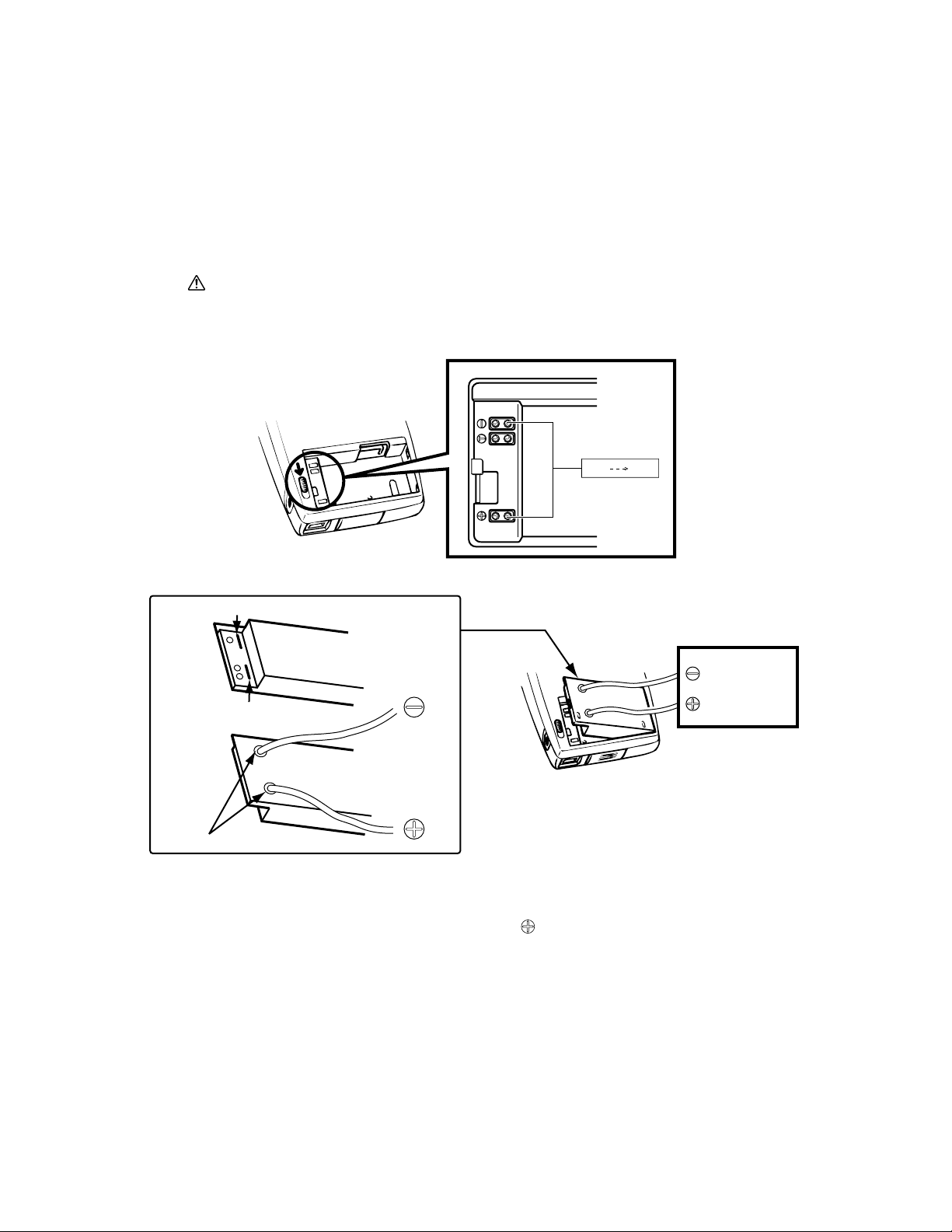
1. Remove the rechargeable main battery and AC adapter.
4.2 V 3.7 V
From
Power Stabilizer
How to supply main voltage
Cut the lines
Main battery
Cut the lines
Main battery
Make hole and connect wire
To POWER
Stabilizer
How to make/use dummy Main battery
2. Using a stylus pen, slide the main battery as shown above.
3. Using DC voltage stabilizer, supply DC voltage (4.2V) to terminal as shown above.
Turn on the unit's power. After that, it is recommended to perform RESET or FULL RESET
operation.
4. Booting the diagnostic program, display Main Menu for the operation check.
5. Make the voltage power supply added to the main battery terminal 4.2 V ± 0.05 V.
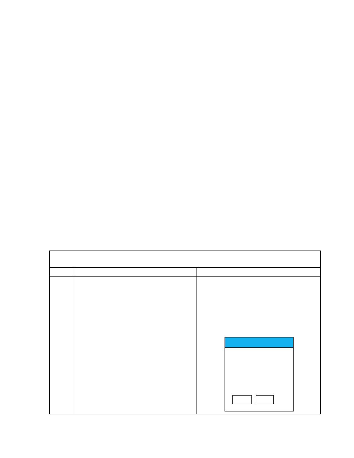
6. Tapping voltage Write, the following display appears.
*** <AD Revision Value Write> ***
<Max Level Write>
Voltage Write-> Contacts Key
Escape -> ON Key
— 12 —
Page 16
7. Pressing Contacts button, the following display appears.
*** <AD Revision Value Write> ***
<Max Level Write>
AD Value Read! 0x8...
<Min Level Write>
V oltage Write-> Contacts Key
Escape -> ON Key
If the unit can not read the voltage 4.2V correctly, "No Good. Please retry!!" message will appear.
Note that the unit can not be progressed in the next stage whenever this message appears.
8. Make the voltage power supply added to the main battery terminal 3.7V ± 0.05V.
Then, press Contacts button again.
Doing so, the following display appears.
*** <AD Revision Value Write> ***
<Max Level Write>
AD Value Read! 0x8...
<Min Level Write>
AD Value Read! 0x8...
V oltage Write-> Contacts Key
Escape -> ON Key
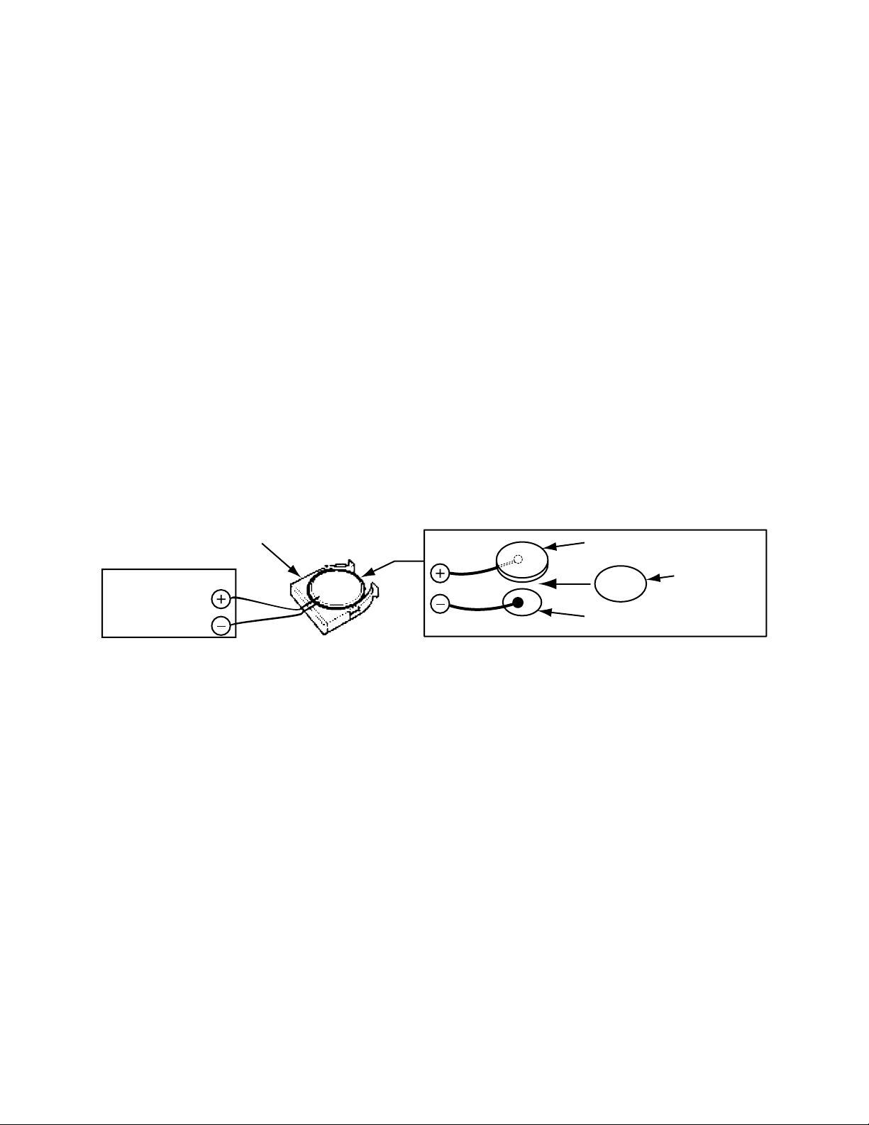
9. Make the voltage power supply added to sub battery terminal 2.7 V ± 0.05 V by using dummy sub battery.
(Refer to following figure for connection)
Note: Main power can be supplied from Ac adapter or main battery.
Battery holder
Large plate
To power stabilizer
Insulata plate
Small plate
Then, press Contacts button again.
Doing so, the following display appears.
*** <AD Revison Value Write> ***
<Max Level Write>
AD Value Read! ****
<Min Level Write>
AD Value Read! ****
<SUB Level Write>
AD Value Read! ****
Write Data Value
Max=**** ;SUb=****
Min=****
10. Pressing Action Control button, the following display appears along with Main Menu display (under Main
Menu display).
AD Code=OOOOO
If missed, the following # display will appear instead of O.
AD Code=# # # # #
If the display appears, be sure to try to perform these settings (adjustments) again.
After turning off the unit power, stop to add the powers to the unit.
Finally , after connecting the rechargeable main battery and AC adapter to the unit, perform Initial Setup or
FULL RESET.
— 13 —
Page 17
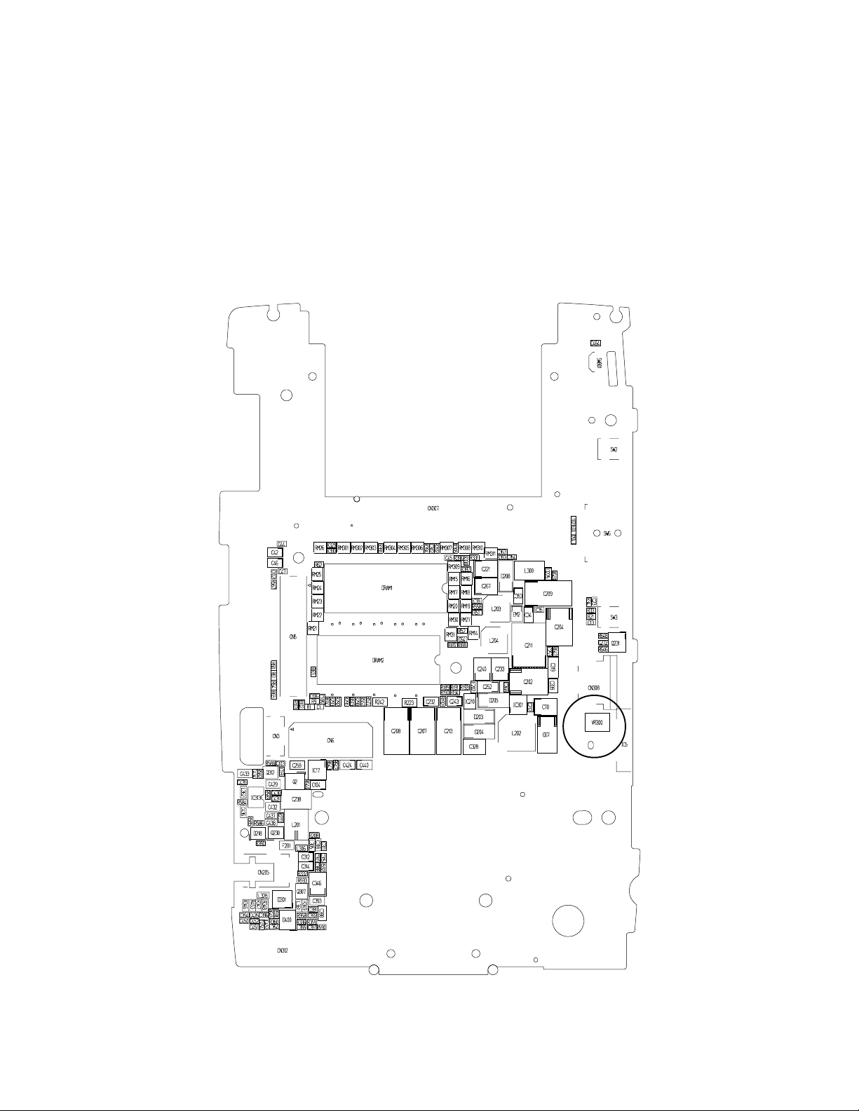
5-2. Display adjustment
1. Perform diagnosis program Main Menu 1 DISPLAY.
2. By tapping touch panel 8 times, the display color becomes GRAY.
3. If abnormal displays (flicker, vertical stripe and so on) are detected, change Vcom voltage rotating the
variable resistor VR300. (refer to location as show figure)
To adjust actually, removing the screws assembled onto the lower case, disassemble the unit as shown
below. Then rotate this variable resistor (VR300) using a ceramic screw driver (minus/ 1.8 mm width) to
make the screen the normal display (no flicker and no stripes).
— 14 —
Page 18
6. OPERATION CHECK
Autorun for DKP700 v1.01
Run Autorun.exe?
DKP700.exe
Diag.exe
DiagRF.exe
Yes No
6-1. Preparation
1.SX45 (Prepare another units to perform IrDA communication check except the checking unit.)
2.Compact Flash Memory Card
3.SD Memory Card
4.Rechargeable battery pack (L36880-N9001-A106)
5.AC adapter (L36880-N9001-A108)
6.Cradle (L36880-N9001-A103) with serial cable (L36880-N9001-A104)
7.Diagnostic program files for SX45 with compact Flash Memory Card
8.Head set
9.One DC Power Supply Stabilizers
10.Screw driver (Y type)
11.Ampere meter/Volt meter
12.USB cable (L36880-N9001-A105)
NOTES:
* Be sure to make back-up copies of all data in the unit before repair using BACKUP/ RESTORE function in
ActiveSync 3.1 software because FULL RESET must be performed to finish or abort this operation check.
Diagnostic program file will be saved in RAM assembled onto the main PC board.
Therefore, performing FULL RESET after this check, this program should be deleted.
These program files (DKP700.exe/ Diag.exe/ DiagRF.exe) will be supplied along with the CF card.
* The unit may be locked during the installation, this check or the other operation.
If this lock occur, try to perform RESET or FULL RESET operation.
6-2. How to install the diagnostic program
Important: There are two kinds of diagnosis program for English version and German version.
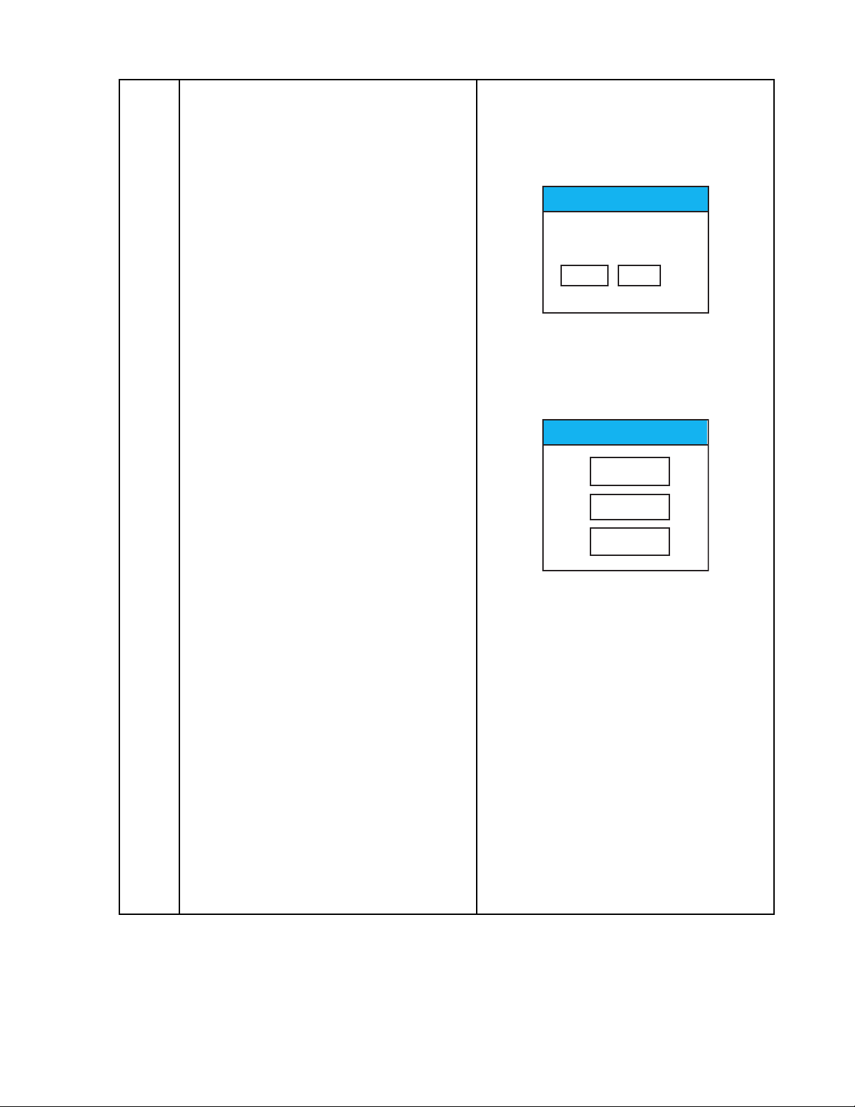
Seq. Operation Display
Make sure the version when the diagnosis program is loaded to the unit.
< Diag installation & Start up, Exit and Change >
< Diag set and Start up >
1 Perform full reset Initial display (welcome) comes up after
full reset
2 Insert CF card which Autorun for DKP700 comes up,
including Diag. Program then return to intial display again
— 15 —
Page 19
3 Tap diplay according to instruction of Autorun for DKP700 message
Soft Rest
After Remove CFcard,
Push [Yes] button.
Yes No
Diag Chg
DKP700
DIAG.exe
DiagRF.exe
display message and set up intial setting again.
for SX45
4 Tap Yes Soft Reset message comes up
5 Remove CF card, then tap Error on GSM connection message
Yes comes up
6 Disregard the error and Tap OK Diag Chg message comes up
7 Tap DIAG.EXE ** Main Menu ** comes up
(As for DKP700 operation, refer to 1 DISPLAY
Chaptor 6-4.) 2 TOUCH PANEL
3 MEMORY
4 SERIAL
5 POWER CONTROL
6 AUDIO
7 OTHERS
8 COLOR BAR
9 VOL TAGE Write
10
11 T E S T AC
12
13 DIAG EXIT
14 DIAG CHANGE
NOTE: As for another operation check, refer to page 25.
— 16 —
Page 20

8 Tap 11TEST AC ** TEST AC ** comes up
1 Power Control
2 Switch
3 Loop Back
4 Loop Back 2
5 USB Check
6 LR-Channel
7 Record
8 Color Bar
9 Keyboard Random Plus
10 ROM Sum/Bus/Type
11 RAM Test
12 SD Check
13 RSSI LED Check
14 Touch Panel Point
15 Back Light
16 Voltage Write
17 Interactive <IrDA Ck>
18 Send/Receive 2 <FIR Ck>
19
20
21 Return to Main Menu
< Diag Exit and Change >
1 Tap 21 Return to Main Menu Return to ** Main Menu **
1 DISPLAY
2 TOUCH P ANEL
3 MEMORY
4 SERIAL
5 POWER CONTROL
6 AUDIO
7 OTHERS
8 COLOR BAR
9 VOL TAGE Write
10
11 T E S T AC
12
13 DIAG EXIT
14 DIAG CHANGE
2 Tap 13 DIAG EXIT Return to intial display
3 Tap 14 DIAG CHANGE Return to Diag Chg menu
Important : If something inoperative performances occur during excution, “Reset” or “Full Reset”
should be done. Then the program can be worked again.
— 17 —
Page 21
6-3. Operation Check
■ 1 Power control
Current Consumption should be checked.
No.
1
Connect terminals of main
battery to Power Stabilizer.
2
Tap the touch panel on 1
POWER CONTROL.
3
Turn to OFF (stand by) the
unit.
4
Press down the ACTION
key.
Operation
Display
** TEST AC ** comes up
1 Power Control
2 Switch
3 Loop Back
4 Loop Back 2
5 USB Check
6 LR-Channel
7 Record
8 Color Bar
9 Keyboard Random Plus
10 ROM Sum/Bus/Type
11 RAM Test
12 SD Check
13 RSSI LED Check
14 Touch Panel Point
15 Back Light
16 Voltage Write
17 Interactive <IrDA Ck>
18 Send/Receive 2 <FIR Ck>
19
20
21 Return to Main Menu
Currently CPU clock is
150MHz
VTCLK is 50MHz
No display
Return to TEST AC MENU.
Check
Measure the main battery
current in page 2 for the details.
Measure the main battery
current in page 2 for the details.
Measure the main battery
current in page 2.
If NG
Main PCB
fault
■ 2 Switch
Switch condition should be checked.
No.
1
Tap the touch panel on 2
Switch.
2
Insert the AC adapter.
3
Remove the AC adapter.
4
Move the battery cover
LOCK dial to Main Battery
Replacement.
5
Move the battery cover
LOCK dial to LOCK.
6
Insert the head set.
7
Press the HOOK button of
the head set.
8
Pull out the Audio Jack.
9
Press down the ACTION
key.
Operation
Display
AC Adpter USED
AC Adpter NOT USED
Cover OPEN
Cover CLOSE
Audio Jack ON
ONHOOK ON
Audio Jack OFF
Return to TEST AC MENU.
Check
Check on red blinking of
Notification LED.
Check on “VDETS OFF”.
Check on “USED.”
Check if Charge LED turns on.
Check on “NOT USED.”
Check if Charge LED turns off.
Check on “OPEN.”
Check on “CLOSED.”
Check on “ON.”
Check on “ON.”
Check on “OFF.”
If NG
LED PCB,
Main PCB
fault
Adaptor
Jack
fault
Card PCB
fault
Main PCB
fault
— 18 —
Page 22
■ 3 Loop Back
Serial Connector condition should be checked.
No.
1
Insert the cradle loop back
Operation
jig into the 20 pin
connector.
2
Tap the touch panel on 3
Loop Back.
3
Press down the ACTION
key.
4
Remove the loop back jig.
5
Press down the ACTION
key.
■ 4 Loop Back2
Cradle Connector condition should be checked.
No.
1
Insert the loop back2 jig
Operation
into the 20 pin connector.
2
Tap on the touch panel on
4 Loop Back2.
3
Remove the loop back2 jig.
4
Press down the ACTION
key.
Display
RS232C ---> OK
DTR-DCD --->OK
DTR-DSR --->OK
DTR-CTS --->OK
Return to TEST AC MENU.
Display
*** LOOP BACK2 ***
---> LOOP BACK2 OK
MPX1-9 pin ---> OK
SEL0 pin ---> OK
SEL1 pin ---> OK
SEL2 pin ---> OK
Return to TEST AC MENU.
Check
Check if all 4 lines show OK.
Check
Check if the top line shows OK,
or check if the rest of the lines
show OK.
If NG
20 pin
Connector
fault
If NG
20 pin
Connector
fault
■ 5 USB Check
USB condition should be checked.
No.
1
Tap the touch panel on 5
USB Check.
After the message in the
right is displayed, connect
the USB cable to the 20
Operation
Display
*** USB CHECK ***
Please connect USB cable
with PC starts with the
Action key
Check
If NG
20 pin
Connector
fault
pin connector of the main
body.
Connect the USB
connector to the USB port
GD23sp(CONF)=1
USB TEST................ OK
Check on OK.
of the computer.
Press down the ACTION
key.
2
Remove the USB tool.
3
Press down the ACTION
Return to TEST AC MENU.
key.
Note: In No. 1, do not connect the USB tool before “Tap the touch panel on 5 USB Check”, or USB TEST
becomes NG.
— 19 —
Page 23
■ 6 LR-Channel
Audio sounds should be checked.
No.
1
Insert the head set.
2
Tap on the touch panel on
Operation
6 LR-Channel.
3
Press down the ACTION
key.
■ 7 Record
Record and Play back sound should be checked.
No.
1
Tap on the touch panel on
Operation
7 Record.
2
Tap on the touch panel on
1 Start Recording. Input
any sound into the inner
microphone.
Press the ACTION key.
3
Tap on the touch panel on
2 Play Recorded Sound.
4
Press the ACTION key.
Display
AUDIO LR_Chanel
Return to TEST AC MENU.
Display
1 Start Recording
2 Play Recording Sound
Exit to Action key push!
Action key push to stop
Recording
The recorded sound
automatically stops in
about five seconds.
1 Start Recording
2 Play Recording Sound
Exit to Action key push!
Action key push to stop
Playing
The Played sound
automatically stops in
about five seconds.
Return to TEST AC MENU.
Check
Check if the sound in the Right
Channel can be heard from the
right ear phone and the sound
in the Left Channel can be
heard from the left ear phone.
Check
Check if the recorded sound
plays normally (check it by the
head set).
If NG
Main PCB
fault
If NG
Main PCB
fault
■ 8 COLOR BAR
Color condition should be checked.
No.
1
Tap on the touch panel on
8 COLOR BAR.
2
Above condition
3
Press ACTION Key or
Cross Up Key.
4
Press ACTION Key or
Cross Up Key.
5
Press the ACTION key.
Operation
The color bar of RGB is
indicated.
Blight = 142
Blight = ✻✻✻
Blight = ✻✻✻
Return to TEST AC MENU.
■ 9 Keyboard Random Plus is not checked.
Display
— 20 —
Check
Check if the coloring is normal.
Check if the gradation of color
in the right is smooth.
The Bright Value is indicated in
the lower part of the screen.
Check on the contrast which
becomes darker as the Bright
Value increases.
Check on the contrast which
becomes lighter as the Bright
Value decreases.
If NG
LCD unit
fault
Page 24
■ 10 ROM Sum/Bus/Type
ROM should be checked.
No.
1
Tap on the touch panel on
Operation
10 ROM SUM/BUS/Type.
2
Tap on the touch panel in
the right.
3
Press the ACTION key.
■ 11 RAM Test
RAM should be checked.
No.
1
Tap on the touch panel on
Operation
11 RAM TEST.
2
Press the ACTION key.
Display
<JX707> Select
T AP This Area!
32MB FLASH ROM
<JX700> Select
T AP This Area!
16MB FLASH ROM
✻✻✻ ROM CHECK SUM
✻✻✻
base addr. sum value
SUM1(be000000) = ✻✻✻✻
SUM1(be000000) = ✻✻✻✻
FLASH Write ---> OK
Return to TEST AC MENU.
Display
✻✻✻ RAM CHECK ✻✻✻
-- RAM CHK OK -Return to TEST AC MENU.
Check
Check on OK.
Refer to exact value in page 2.
Check
Check on OK.
If NG
ROM
PCB
fault
If NG
Main PCB
fault
■ 12 SD Check
SD card should be checked.
No.
1
Insert the SD card with
Operation
write protect OFF.
2
Tap on the touch panel on
12 SD CHECK.
3
Press the ACTION key.
Pull out the SD card.
Display
Clock; 9.216MHz...CMD9 OK ;CMD10 OK
Clock; 4.608MHz...CMD9 OK ;CMD10 OK
Clock; 2.304MHz...CMD9 OK ;CMD10 OK
Clock; 1.152MHz...CMD9 OK ;CMD10 OK
Clock; 0.576MHz...CMD9 OK ;CMD10 OK
Clock; 0.288MHz...CMD9 OK ;CMD10 OK
Check on OK.
Return to TEST AC MENU.
Check
If NG
Card PCB
fault
— 21 —
Page 25

■ 13 RSSI LED Check
LEDs should be checked.
No.
1
Turn on Com SW so that
Operation
the LED can be seen.
2
Tap on the touch panel on
13 RSSI LED Check.
3
Tap on the touch panel.
4
Tap on the touch panel.
5
Tap on the touch panel.
6
Tap on the touch panel.
■ 14 Touch Panel Point
Touch Panel function should be checked.
No.
1
Tap on the touch panel on
Operation
14 TOUCH PANEL.
Display
RED LED ON
NEXT ---> TAP TP
GREEN LED ON
NEXT ---> TAP TP
ORANGE LED ON
NEXT ---> TAP TP
LED OFF
NEXT END ---> TAP TP
Return to TEST AC MENU.
Display
Check
Check if the red LED turns on.
Check if the green LED turns
on.
Check if the orange LED turns
on.
Check if the LED turns off.
Check
If NG
LED PCB
fault
If NG
Touch
Panel,
Main PCB
fault
2
Tap on the four points of
the cross.
3
Press the ACTION key.
■ 15 Back Light
Back Light condition should be checked.
No.
1
Tap on the touch panel on
Operation
15 Back Light.
2
Tap on the four points of
the cross.
3
Press the ACTION key.
Touch Panel -------> OK
Return to TEST AC MENU.
Display
-->Push CrossDown or
CrossUp KEY!
--> BackLight Chage
197
------------------------------------
Return to TEST AC MENU.
If the four points of the cross do
not disappear, tapping is NG.
Check
Check if the Back Light turns
on.
Check if the Back Light
becomes darker. Also check if it
becomes lighter again after
turning darkest.
If NG
Inverter
PCB,
LCD unit
— 22 —
Page 26

■ 16 Voltage Write
AD converter value should be checked and adjusted.
No.
1
Tap on the touch panel on
Operation
16 VOLTAGE Write.
2
Supply the main battery
terminals with 4.2 V.
3
Press the Contact key.
4
Supply the main battery
terminals with 3.7 V.
5
Press the Contact key.
6
Supply the sub battery
terminals with 2.7 V.
7
Press the Contact key.
8
Press the ACTION key.
9
FULL RESET
Display
✻✻✻<AD Revison Value Write>✻✻✻
<Max Level Write>
Voltage Write->Contacts Key
Escape -> ON Key
Escape -> CrossDown Key
✻✻✻<AD Revison Value Write>✻✻✻
<Max Level Write>
AD Value Read!
<Min Level Write>
Voltage Write->Contacts Key
Escape -> ON Key
Escape -> CrossDown Key
✻✻✻<AD Revison Value Write>✻✻✻
<Max Level Write>
AD Value Read!
<Min Level Write>
AD Value Read!
Voltage Write->Contacts Key
Escape -> ON Key
Escape -> CrossDown Key
✻✻✻<AD Revison Value Write>✻✻✻
<Max Level Write>
AD Value Read! ✻✻✻✻
<Min Level Write>
AD Value Read! ✻✻✻✻
<SUB Level Write>
AD Value Read! ✻✻✻✻
Write Data Value
Max=✻✻✻✻ ;SUb=✻✻✻✻
Min=✻✻✻✻
AD Code = OOOOO
NG Code = #####
Check
Note: Refer to 7. ADJUSTMENT
for details.
Check the message.
If NG
Main PCB
fault
— 23 —
Page 27

■ 17 Interactive <IrDA Ck>
IrDA functions should be checked.
No.
Operation
TEST UNIT
1
Tap on the touch panel on
17 Interactive <IrDA Ck>.
2
Perform operations 1b and
2b on the master unit.
3
Tap on the touch panel.
4
Start communication and
enter the wait mode again.
5
Press the ACTION key.
MASTER UNIT
1b
Tap on the touch panel on
17 Interactive <IrDA Ck>.
2b
Tap on the touch panel.
■ 18 Send/Receive 2 <FIR Ck>
FIR functions should be checked.
No.
Operation
TEST UNIT
1
Tap on the touch panel on
18 Send/Receive 2 <FIR
Ck>.
2
Tap on the 2 Receive data
(4 Mbps).
3
Perform operations 1b to
4b on the master unit.
4
Press the ACTION key.
5
Perform operations 5b on
the test master.
6
Tap on the touch panel on
Send data (4Mbps).
7
Check if the screen returns
to the display in the right
after a few seconds. Also
check on the display in the
master unit.
8
Perform operations 6b on
the master unit.
9
Press the ACTION key.
Display
Ready
Check if the wait mode for send
/receive starts.
Ready
Check on OK and Ready.
OK
Ready
Return to TEST AC MENU.
Ready
Ready
Ready
Check if the wait mode for send
/receive starts.
Display
<Fast Infrared SEND/RECEIVE 2>
1 Send data (4Mbps)(6400BYTE)
2 Receive data (4Mbps)(Probability)
<Receive mode>
Check if the wait mode for
receive status.
<Receive mode>
Receive Rate (%) : ✻✻✻.✻
Check if ‘***. *’ is over the
standard value.
If it is below the standard value
or nothing appears, the
operation is NG.
<Fast Infrared SEND/RECEIVE 2>
1 Send data (4Mbps)(6400BYTE)
2 Receive data (4Mbps)(Probability)
<Send mode>
<Fast Infrared SEND/RECEIVE 2>
1 Send data (4Mbps)(6400BYTE)
2 Receive data (4Mbps)(Probability)
Return to TEST AC MENU.
Check
Check
If NG
Main PCB
fault
If NG
Main PCB
fault
— 24 —
Page 28

No.
Autorun for DKP700 v1.01
Run Autorun.exe?
DKP700.exe
Diag.exe
DiagRF.exe
Yes No
MASTER UNIT
1b
Tap on the touch panel on
18 Send/Receive 2 <FIR
Ck>.
2b
Tap on the touch panel on
18 Send/Receive 2 <FIR
Ck>.
3b
Tap on the touch panel on
Send data (4Mbps).
4b
Check if the screen returns
to the display in the right
after a few seconds. Also
check on the display in the
master unit.
5b
Tap on the touch panel on
Receive data (4Mbps).
6b
Press the ACTION key.
Operation
Display
<Fast Infrared SEND/RECEIVE 2>
1 Send data (4Mbps)(6400BYTE)
2 Receive data (4Mbps)(Probability)
<Send mode>
<Fast Infrared SEND/RECEIVE 2>
1 Send data (4Mbps)(6400BYTE)
2 Receive data (4Mbps)(Probability)
<Receive mode>
Receive Rate (%) : ✻✻✻.✻ OK
Return to TEST AC MENU.
6-4. Operation check for diagnosis program DKP700. exe
Check
Check if ‘***. *’ is over the
standard value.
If it is below the standard value
or nothing appears, the
operation is NG.
If NG
This diagnosis program can obtain various system information, and check each function of unit.
< Operation of DKP700 >
Seq. Operation Display
< Diag set and Start up >
1 Perform full reset Initial display (welcome) comes up after
full reset
2 Insert CF card which Autorun for DKP700 comes up,
including Diag. Program then return to intial display again
3 Tap diplay according to instruction of Autorun for DKP700 message
display message and set up intial setting again.
for SX45
— 25 —
Page 29

4 Tap Yes Soft Reset message comes up
Soft Rest
After Remove CFcard,
Push [Yes] button.
Yes No
Diag Chg
DKP700
DIAG.exe
DiagRF.exe
5 Remove CF card, then tap Error on GSM connection message
Yes comes up
6 Disregard the error and Tap OK Diag Chg message comes up
7 Tap DKP700
DKP_700
6:20PIN PORT CHECK
9:VOLTAGE CHECK
10:AD VALUE TEST
Top
0:INFORMATION
1:MEMORY TEST
2:DISPLAY
3:T -PANNEL
4:JACK TEST
5:AUDIO TEST
7:IRDA SIR TEST
8:IRDA FIR TEST
11:SWITCH TEST
12:KEY CHECK
-
DiagChg.exe
Rem < >
— 26 —
Page 30

■ 0 INFORMATION
Tap the touch “0 INFORMATION”.
DKP_700
Program Version
ROM Infomation
RAM Infomation
E2P Information
UUID_INFO
-
-
-
-
-
-
-
-
-
-
Top
Rem < >
No.
1
Tap the touch Program Version.
Operation
Tapping anywhere returns to the
previous display .
2
Tap the touch ROM Information.
Tapping anywhere returns to the
previous display .
3
Tap the touch RAM Information.
Tapping anywhere returns to the
previous display .
4
Tap the touch E2P Information.
Tapping anywhere returns to the
previous display .
5
Tap the touch UUID_INFO.
Display
Version Infomation
Soft_Ver:0.21
Lib_Ver : JX700_008
TCC Version:0.07
[Internal Storage Information (ROM)]
ROM_TYPE:FLASH ROM
ROM_SIZE:128MB
[Internal Storage Information (RAM)]
RAM_TYPE:SRAM
RAM_SIZE:256MB
[Internal Storage Information (EEPROM)]
EEPROM_SIZE:2KB
UUID_INFO:
Jx700-2001-AICHI
xxxxxx
Check
Tapping anywhere returns to the
previous display.
Tapping “Top” returns to DKP700 menu.
EEP:002BC-01-20-xxxxxx
— 27 —
Page 31

■ 1 MEMORY TEST
Tap the touch “1 MEMORY TEST”.
DKP_700
CHECK SUM VALUE
RAM Read/Write
E2P Read/Write
FLASH Read/Write
CF CARD CHECK
SD CARD CHECK
-
-
-
-
-
-
-
-
-
Top
Rem < >
No.
1
Tap the touch CHECK SUM
Operation
VALUE.
Tapping anywhere returns to the
previous display .
2
Tap the touch RAM Read/Write.
Tapping anywhere returns to the
previous display .
3
Tap the touch E2P Read/Write.
Tapping anywhere returns to the
previous display .
4
Tap the touch FLASH Read/
Write.
Tapping anywhere returns to the
previous display .
5
Tap the touch CF CARD CHECK.
Tapping anywhere returns to the
previous display .
6
Tap the touch SD CARD CHECK.
Tapping anywhere returns to the
previous display.
Tapping “Top” returns to DKP700 menu.
Display
ROM SUM
Check Sum (16+16) : 0x332FDD20
Check Sum ( 32) : 0xE88CDD20
Check Sum ( XOR) : 0x2D612A96
Note: Check sum can be changed
without notice
RAM R/W
32bit : OK
16bit : OK
8bit : OK
All : OK
EEPROM R/W TEST
OK
FLASH R/W TEST
OK
CF Card :
Insert:OK
Maker :xxMB
SD Card :
Insert:OK
Protect: OFF
CSD :
FE 00 2D 00 - 32 13 59 80 E3 76 D9 8F - 80 16 40 00 0F 50 E8 00 CID :
FE 02 54 4D - 53 44 30 31 36 00 30 3B - A2 01 00 13 17 A0 08 00 -
Check
— 28 —
Page 32

■ 2 DISPLAY
Tap the touch “2 DISPLAY”.
DKP_700
BLACK PAINT
WHITE PAINT
GRAY PAINT
BOX1 PAINT
STRIPE PAINT
BACKLIGHT PAINT
BLIGHT PAINT
RSSI1 LED
RSSI2 LED
NOTIF LED
-
-
-
-
-
Top
Rem < >
No.
1
Tap the touch BLACK PAINT.
Operation
Tapping anywhere returns to the
previous display .
2
Tap the touch WHITE PAINT.
Tapping anywhere returns to the
previous display .
3
Tap the touch GLAY PAINT.
Display Check
Tapping anywhere returns to the
previous display .
4
Tap the touch BOX1 PAINT.
Tapping anywhere returns to the
previous display .
— 29 —
Page 33

No.
5
Tap the touch STRIPE PAINT.
Operation
Tapping anywhere returns to the
previous display .
6
Tap the touch BACKLIGHT
P AINT.
Pressing the ACTION key returns
to the previous display.
7
Tap the touch LIGHT PAINT.
Display
Check
Pressing the ACTION key returns
to the previous display.
8
Tap the touch RSSI1 LED.
Tapping anywhere returns to the
previous display .
9
Tap the touch RSSI2 LED.
Tapping anywhere returns to the
previous display .
10
Tap the touch NOTIF LED.
Red lights.
LED ON : RED
Green lights.
LED ON : GREEN
Red blinks.
LED ON : RED BLINK
Tapping anywhere returns to the
previous display.
Tapping “Top” returns to DKP700 menu.
— 30 —
Page 34

■ 3 T-PANNEL
Tap the touch “3 T-PANNEL”.
DKP_700
T-PANNEL CHECK
T-PANNEL POINT
-
-
-
-
-
-
-
-
-
-
-
-
-
Top
Rem < >
No.
1
Tap the touch T-P ANNEL
Operation
CHECK.
Pressing the ACTION key returns
to the previous display.
2
Tap the touch T-PANNEL POINT.
Display
Tapped position is indicated by a cross.
< 119>< 267>
Check
Pressing the ACTION key returns
to the previous display.
Tapping “Top” returns to DKP700 menu.
< 119>< 267>
Tapped position is indicated by a cross
and axis.
— 31 —
Page 35

■ 4 JACK TEST
Tap the touch “4 JACK TEST”.
DKP_700
-
HEAD CHECK
AC ADAPTOR CHECK
-
-
-
-
-
-
-
-
-
-
-
-
Top
Rem < >
No.
1
Insert the head set.
Operation
Tap the touch HEAD CHECK.
Tapping anywhere returns to the
previous display .
2
Insert the AC adaptor.
Tap the touch AC ADAPTOR
CHECK.
Tapping anywhere returns to the
previous display .
Tapping “Top” returns to DKP700 menu.
Display
HEAD :
ON
--------
--------
--------
--------
--------
--------
--------
--------
--------
RECHARGE :
[Recharge] : [Adapter]
ON : ON
--------- : -------
--------- : -------
--------- : -------
--------- : -------
--------- : -------
--------- : -------
--------- : -------
--------- : -------
--------- : -------
Check
— 32 —
Page 36

■ 5 AUDIO TEST
Tap the touch “5 AUDIO TEST”.
DKP_700
FUNCTION CHECK
TONE 0.5kHz
TONE 1.0kHz
TONE 2.0kHz
REC CHECK
PLAY CHECK
L/R CH CHECK
-
-
-
-
-
-
-
-
Top
Rem < >
No.
1
Tap the touch FUNCTION
Operation
CHECK.
Tapping anywhere returns to the
previous display .
2
Tap the touch TONE 0.5kHz.
Tapping anywhere returns to the
previous display .
3
Tap the touch TONE 1kHz.
Tapping anywhere returns to the
previous display .
4
Tap the touch TONE 2kHz.
Tapping anywhere returns to the
previous display .
5
Tap the touch REC CHECK.
Audio T est :
Rec & Play : OK
Tone :0.5khz
Tone :1.0khz
Tone :2.0khz
[ Recording ]
Display
Check
Tapping anywhere returns to the
previous display .
6
Tap the touch PLAY CHECK.
Tapping anywhere returns to the
previous display .
7
Tap the touch L/R CH CHECK.
Tapping anywhere returns to the
previous display .
Tapping “Top” returns to DKP700 menu.
recording about 5 seconds
automatically
[ Playing ]
playing back the recorded sound
Sound check
Tone : L/R
— 33 —
Page 37

■ 6 ~ 10
Refer to 6-3.Operation Check as the test items are the same as those in diag.exe.
■ 11 SWITCH TEST
Tap the touch “11 SWITCH TEST”.
DKP_700
BATTERY COVER
MODULE POWER
-
-
-
-
-
-
-
-
-
-
-
-
-
Top
Rem < >
No.
1
Tap the touch BATTERY COVER.
Operation
Tapping anywhere returns to the
previous display .
2
Tap the touch MODULE POWER.
Tapping anywhere returns to the
previous display .
Tapping “Top” returns to DKP700 menu.
Battery :
ON
--------
--------
--------
--------
--------
--------
--------
--------
--------
COM SW :
OFF
--------
--------
--------
--------
--------
--------
--------
--------
--------
Display
Check
— 34 —
Page 38

■ 12 KEY CHECK
Tap the touch “12 KEY CHECK”.
DKP_700
KEY PUSH CHECK
-
-
-
-
-
-
-
-
-
-
-
-
-
-
Top
Rem < >
No.
1
Tap the touch KEY PUSH
Operation
CHECK.
2
Push the Reset button after
completing the check.
Display
00000--00-0----0--------------
(O)
O
O
Pushed keys are displayed.
-------- 0 --------
-> Action
Check
— 35 —
Page 39

7. TROUBLE SHOOTING
7-1. Function/Operation troubles for PDA/GSM
Refer to the troubleshooting accordance with the following User Guide
• SX45 PDA Functionality
• SX45 GSM Functionality
• SX45 Pocket PC
7-2. Hard trouble for PDA/GSM
No power at all
Possible cause Recommend action
Main battery discharged Recharge the battery
Wrong position of battery cover switch Set proper position
AC adaptor fault Replace AC adapotor
No main battery is set when AC adaptor is used Set main battery during any operation
Terminals of main battery are dirty Clean the terminals
Broken switch of battery lock key Replace the switch of card PCB
Open circuit of internal PCB Replace main PCB unit
Intermittently no power
Possible cause Recommend action
Low main battery Recharge the battery
Poor contact adaptor jack Change the jack
Poor contact of battery cover switch Change the switch
Terminals of main battery are dirty Clean the terminals
Poor contact of internal connector Check and reconnect
Lock up during operation
Possible cause Recommend action
Data is full in memory Perform reset operation
Data corruption in RAM Perform reset operation
Performed improper application software Delete the improper application software
Internal PCB fault Replace main PCB
No display/No back light (other functions OK)
Possible cause Recommend action
Poor soldering of connector at main PCB Resolder connector pins
Poor contact of inverter cable Check and reconnect
Poor contact of connector Reconnect the LCD cable
Internal PCB fault Replace inverter PCB
LCD (of back light lamp) fault Replace LCD unit
Erratic display
Possible cause Recommend action
Faulty LCD Replace LCD unit
Poor connection of LCD cable Check and reconnect
Faulty internal PCB Replace main PCB unit
— 36 —
Page 40

No audio sound
Possible cause Recommend action
Poor contact of audio connector Replace audio connector
Faulty internal PCB Replace main PCB unit
Faulty speaker Replace the speaker
No input at all
Possible cause Recommend action
Out of calibration of touch panel Recalibrate the touch panel
Scratch(damage) on touch panel Replace the touch panel
Poor contact of connector Reconnect the touch panel cable
Internal data malfunction Reset(or full reset) the unit
Short circuit of key Replace short switch
Data error message
Possible cause Recommend action
Internal data malfunction(corruption) Reset(or full reset) the unit
Weak of main and sub battery Check voltage of main and sub battery
Faulty RAM Replace main PCB unit
Poor contact of connector Check the connection and reconnect
No communication with PC
Possible cause Recommend action
Poor contact of serial connector Check and repair the connector
Open circuit(damage) of serial connector Check and replace the connector
Faulty internal PCB Replace main PCB unit
Short battery life(current consumption too high)
Possible cause Recommend action
Faulty or end of life main battery Replace new main battery
Short circuit of connector pins Check and resolder
Short circuit of internal PCB Check and replace main PCB
CF/SD/MM card cannot read
Possible cause Recommend action
Not designated(improper) card Swap to recommended(proper) card
Broken(or bend) pins of card slot Replace card slot or card/main PCB
Faulty internal PCB Replace main or card PCB
Too slow response of input
Possible cause Recommend action
Low available of memory capacity Reset the unit
Poor contact of touch panel and keys Check the switch and connection
— 37 —
Page 41

No LED indication
Possible cause Recommend action
Poor contact of connector Check the connection and reconnect
Faulty internal PCB Replace LED PCB
Switches/buttons do not move smoothly
Possible cause Recommend action
Action key motion is no good Check the gap at action key and case
Cursor key motion is no good Check the two spacer at internal Cursor key
Too tight GSM switch Check the knob or holder position of switch
Pocket Dialer Cannot be switched ON
Possible Cause Recommended Action
GSM switch “OFF” or does not work Check the position/condition of GSM switch
Poor contact of COM module connector Check the contact and reconnect
Faulty COM module or internal PCB Replace faulty block
SIM error
Possible Cause Recommended Action
SIM card not inserted completely Make sure the SIM card condition
Poor contact of pin contacts dirty/bend Clean/repair the pin contacts
SIM card faulty/damaged Replace the SIM card
Open circuit of card PCB Replace the card PCB
No call(other functions work)
Possible Cause Recommended Action
Signal weak Move to better radio condition area
Out of GSM range Check the service area
SIM card not valid Swap the SIM card and try
Poor contact of ANT cable Check the connection and repair
ANT PCB faulty/damaged Replace the ANT PCB
Headset jack poor contact or faulty Replace the headset
Poor contact of COM module connector Check the contact and reconnect
Faulty COM module or internal PCB Replace faulty block
Phone voice not clear/distortion(other functions work)
Possible Cause Recommended Action
Faulty COM module or main PCB Replace faulty block
Faulty headset Replace the headset
No internet/no e-mail(other calls work)
Possible Cause Recommended Action
Access not set up/configured Start Auto Configulator and check the setting
— 38 —
Page 42

— 39 —
8. CIRCUIT BLOCK DIAGRAM
Page 43

9. WIRING DIAGRAM
JX700 Block Diagram
Inverter
Touch Panel
CN3
4Pin
FPC
54550-0690
CN308
54104-4590
LCD
with
Back Light
45Pin
FPC
CN4
Lithium
Ion
Battery
EVQQWN03W
ABC2101P
SOT-154HST
ABC2101P
883012
CN312
SLLB120400
EVQPSC02K
52271-0490
SOT-
152HST x 4
CN6
54132-4090
CN701
CN702
CN307
CN5
CN1
JC26A-BB-E1050(JAE)
JC26A-FRM(JAE)
50pin
BtoB
SIM
Card
CN705
Reset
SW
Battery
LockSW
FMS006-2000-000 FPS009C24590
AXK6S50645P
54550-0890
53949-0808
54150-0808
54548-0890
CN801
CN311
CN313
CN310
AXK5S30045P
AXK5S50245P
PCB-J700-1
(C141203-1)
J700-1 ASSY
(C141202*1)
AXK6S3054P
CN90
Backup
Battery
IrDAVOICE
SW
Rocker
KEY
COM
ON/OFF
SW
ON/OFF
SW
Headset
I/F
AC Adapter
HEC3604-010110
PCB-J700-KEY
(C241950-1)
J700-KEY ASSY
(C343977*1)
PCB-J700-LED
(C343987-1)
J700-CARD ASSY
(C343976*2)
PCB-J700-FRM
(C241952-1)
J700-FROM ASSY
(C343975*1)
PCB-J700-CARD
(C241951-1)
J700-CARD ASSY
(C343976*1)
30pin
BtoB
MICSP
Appli
KEY2
Charge
LED
RSSI
LED
Notificatio
n
LED
Appli
KEY1
Appli
KEY3
Cursor
KEY3
20Pin
Serial I/F
TCX3130-010100
80Pin
BtoB
CN704
SD
Card
EXT ANT
Antenna
PCB
CF Card
GSM
Cellular
Engine
(TC-35)
— 40 —
Page 44

10. SCHEMATIC DIAGRAMS
10-1. MAIN BLOCK
— 41 —
Page 45

10-2. POWER BLOCK
— 42 —
Page 46

10-3. AUDIO BLOCK
— 43 —
Page 47

10-4. REF BLOCK
— 44 —
Page 48

10-5. CARD BLOCK
— 45 —
Page 49

10-6. KEY BLOCK
— 46 —
Page 50

10-7. FROM BOARD BLOCK
— 47 —
Page 51

10-8. INDICATOR BLOCK
— 48 —
Page 52

10-9. CRADLE BLOCK
— 49 —
Page 53

11. PCB VIEW
J700-1 PCB
TOP VIEW
— 50 —
Page 54

J700-1 PCB
F201
BOTTOM VIEW
F202
— 51 —
Page 55

J700-CARD PCB
BOTTOM VIEW
TOP VIEW
— 52 —
Page 56

J700-KEY PCB
TOP VIEW
BOTTOM VIEW
J700-FRM PCB
— 53 —
Page 57

J700-IND PCB
J623-CR1(MAIN) PCB
TOP VIEW
BOTTOM VIEW
J623-CR1(MAIN) PCB
J623-CR1(SUB) PCB
F1
— 54 —
Page 58

12. DISASSEMBLY PROCEDURE
1. Remove the stylus, Backup Battery, Battery Pack, and CF
Cover.
2. Remove three screws.
Screw
NOTE : Return the Battery Lock Key to the LOCK position.
3. Separating the Lower Case.
Remove the hooks as shown in the procedure. (Be careful at hook position of the Lower Case.)
1
3
5
Hook
Screw
6
4
2
Hook
Reference:
Alternative way for separating the Lower Case.
Hold the main body tight with both fingers as shown below and pull out the Lower Case as hard as possible.
(Pull out the Lower Case with considerable strength.)
— 55 —
Page 59

4. Remove three screws.
Remove the Holder.
Holder
Screws
5. “While paying attention to the jog dial, open the case in both
sides, lift up the Rumberg Connector and remove the Main PCB
unit and the LCD assy.”
Rumberg Connector
5. Remove three screws.
7. Remove the connectors at two places and separate the Main
PCB unit from the LCD assy.
Connector
— 56 —
Page 60

8. Remove two screws.
Remove the Touch Panel.
Screws
9. Disconnect the connector and remove the Inverter assy.
— 57 —
Page 61

10. Remove the sticker and cut off the LCD Holder from the LCD while paying attention to the FPC.
FPC FPC
11. Remove the LED PCB.
NOTE: Be very careful not to make any scratches on the FPC when removing the
sticker.
— 58 —
Page 62

12. Remove four screws and then the KEY PCB.
13. “Remove the IrDA Cover, LED Cover and Side Key.”
LED Cover Side Key IrDA Cover
Screws
14. Remove the Upper Panel.
15. Remove three keys.
NOTE: Put the keys back into the slots tight when fixing them.
KEY PCB
16. Remove a screw and then the PEN Holder.
Screws
PEN Holder
Hook
— 59 —
Page 63

17. Remove six screws and two SNAPs.
Remove the INNER Case.
SNAPs
Unlocked
Locked
18. Remove the Shield Plate and CF Shield as shown in the figure.
CF Shield
Shield Plate
Wipe with alcohol and remove grease.
Wipe with alcohol and
remove grease.
19. Remove the CARD PCB ASSY.
NOTE : Make sure that the Battery Lock Key is in the LOCK
position.
— 60 —
Wipe with alcohol and
remove grease.
CARD PCB
Page 64

20. Remove three screws and the MODULE.
Remove two screws and the Battery Lock Key.
Screws
MODULE
Battrey Lock Key
Screws
— 61 —
Page 65

13. ASSEMBLY PROCEDURE
1. Check on the Spacer and the Cushion.
Spacers
Cushion
2. Check if the Battery Lock Key is in the LOCK position.
Check if the following items are properly fixed;
• CF Lever
• Shied Plate and Spacer
• CF Shield
NOTE : Make sure to replace the SNAPs with new ones.
Push SNAPs into the unlocked position and
turn them to the locked position.
SNAPs
Unlocked
Locked
3. Check on two Cushions and two Spacers on KEY PCB.
CF Lever
CF Shields
Shield Plate
Spacers
Battery Lock Key
— 62 —
Cushions
Spacers
Page 66

4. Be careful with the direction in which the LED Cover
and IrDA Cover should be fixed.
Check on two Spacers on Cursol key.
5. Check on three Spacers and one insulation sheet.
LED Cover
IrDA Cover
Spacers
6. Touch Panel Assembly
Hold the Touch Panel Spacer and the Touch Panel in
the position shown in the figure and fix them together.
Check if the three places circled in the figure match.
Insulation sheet
— 63 —
Page 67

7. LED PCB Assembly
Fix the Shield Plate and the FPC in the direction of the
arrow in the LED PCB.
8. Main PCB and LCD assy Assembly
Connect the LCD Cable and the LED cable tightly.
9. Connect the FPC from the Inverter PCB and the FPC
from the Touch Panel tightly.
10. Turn the Communication SW to OFF and fix it temporarily with Scotch tape.
While paying attention to the Jog SW, widen the Upper
case as shown in the figure and put the Main PCB unit
into the Upper case.
— 64 —
Page 68

11. Put the Holder as shown in the figure. Fix three screws.
Make sure that the PCB unit does not touch the Hook.
Check on the Water Seal.
12. Assemble the main body while paying attention to the
Hook.
Hook
Holder
Water Seal
NOTE : In case the main body does not close normally
because of the Hook, push the Hook inside by
using the minus driver.
— 65 —
Page 69

14. DIAGNOSIS FLOW CHART
Start
Check defect details and appearance
Can defect confirm
repeatly ?
YES
No display at all ?
YES
Make sure battery
lock key position
Cehck main battery voltage
and main current
Is main battery and
current OK ?
NO
NO
NO
Is neccessity of
data back up ?
NO
Change main battery
YES
Take data back up
by CF card or Active Sync
Perform relevenat operation
check program
NO
Is any defect found ?
YES
YES
Perform full reset
Recover ?
NO
Change main PCB unit
A B C
YES
— 66 —
Page 70

A
Is display damaged
or erratic display ?
YES
Change LCD assy
Is neccessity of
data back up ?
NO
Does the defect
cause PDA or COM
module ?
NO
NO
YES
YES
B C
Take data back up by CF card
or Active Sync
Note: If LCD is damaged or main PCB is replaced,
the user data cannot be backed up
Refer to troubleshooting
And perform operation
check program to identify faulty block
Repair or replace
faulty blcok
Perform relevant operation
check program
Perform full reset
Set GSM switch OFF
Check appearance
Refer to troubleshooting
And perform function
check to identify faulty block
Restore the data back up
if it took it
Finish
— 67 —
Page 71

15. TOOL LIST
Tool Specification Test Q'ty
Head set For SX45 Audio check 1pcs
Master Product B2S (or other ver.) sample IrDA 1pcs
AC adaptor L36880-N9001-A108 All 1pcs
Li-ion rechargeable battery L36880-N9001-A106 All 1pcs
Serial (232C) cable L36880-N9001-A104 All 1pcs
Cradle (Sync-Station) L36880-N9001-A103 Serial check 1pcs
USB cable L36880-N9001-A105 USB check 1pcs
Diagnosis prog. with CF card English & German ver. All 2pcs
Current check jig For SX45 Current check 1pcs
Case opener jig For SX45 Disassemble 1pcs
Loop back jig For SX45 Serial check 1pcs
Screw driver (Y type) For SX45 Disassemble 1pcs
Power stabilizer General AD set, Current check 1 or 2pcs
Volt meter General AD set, Current check 1pcs
Ampere meter General AD set, Current check 1pcs
Lithium battery CR2032 All 1pcs
CF card More than 8MB R/W check, Backup 2pcs
SD card More than 8MB R/W check 1pcs
— 68 —
Page 72

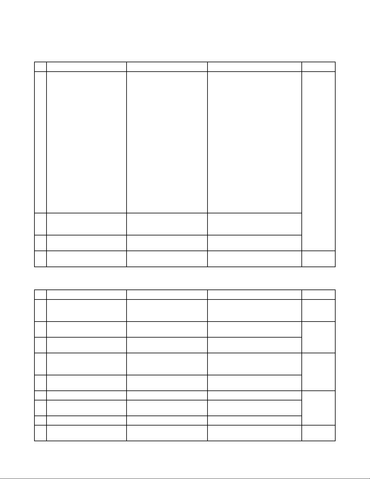
16. PARTS LIST
Item
1 1006 4341 PCB UNIT/MAIN C241936*1 TK English ver. 1
1 1007 2231 PCB UNIT/MAIN C241936*2 TK German ver. 1
2 1006 4342 LCD ASSY C141190*1 TK Common 1
3 1006 2303 PCB ASSY/KEY C343977*1 TK Common 1
4 1006 2306 PCB ASSY/CARD C343976*1 TK Common 1
5 1006 1022 CASE SUB ASSY/LOWER C343952*1 Common 1
6 1006 5917 PANEL/UPPER C242002-1 Common 1
7 1006 1003 CASE/UPPER C241923-1 Common 1
201 ANTENNA/PCB L36880N9000X500 Common 1
202 MODULE/WIRELESS L36880N8100A100 Common 1
CN312 CONNECTOR/RUMBERG L36880N9000C2621 Common 1
204 HEADSET HBH0085-010030 Common 1
205 CD-ROM(MS) CDJ700AA01A English ver. 1
205 CD-ROM(MS) CDJ702AA01A German ver. 1
Parts
Code
Essential Parts(assy/individual) for repair
(Incl. J700-1,FROM,JOG/W,BAT.SP,Shield,etc)
(Incl. J700-1,FROM,JOG/W,BAT.SP,Shield,etc)
(Incl. LCD,HOLDER,INV,TP,LED PCB,etc)
Essential Parts (supplied by Siemens)
Part Name Specification Applicable Q'ty
Stock Recommend Parts
(Lower case block)
8 1006 1016 LEVER/HOOK C343887-1 Common 1
9 1006 1017 LEVER/HOLDER C343888-1 Common 1
10 1006 1018 LEVER/CF C343891-1 Common 1
11 1006 2018 FFC/MODULE C445100-1 Common 1
12 1006 1019 HOLDER/PEN C343892-1 Common 1
13 1006 1020 COVER/SERIAL C343894-1 Common 1
14 1006 1014 CASE/INNER C241925-1 Common 1
15 1006 1032 CASE/SHIELD C343980-1 Common 1
16 1006 1021 SNAP C343904-1 Common 2
17 1006 5755 SHIELD C344023-1 Common 1
18 1006 5785 CUSHION/B C445179-2 Common 1
19 1006 5918 SHIELD/CF C445210-1 Common 2
20 1007 2558 TAPE/INSULATION RJC500160-1 Common 1
21 1007 2270 SPACER/PET/A RJC500145-1 Common 2
22 1007 2271 SPACER/PET/B RJC500145-2 Common 2
23 1007 2556 SPACER/M RJC500159-1 Common 1
24 1007 2273 SHEET/AL RJC500124-1 Common 1
25 1007 2274 SHEET/CF RJC500123-1 Common 2
203 1006 2582 CABLE/ANTENNA MXTK92TK0250 Common 1
(Upper case block)
26 1006 0986 KEY/CURSOR C343899-1 Common 1
27 1006 0987 KEY/IC C343900-1 Common 1
28 1006 0988 KEY/SCHEDULE C343901-1 Common 1
29 1006 0989 KEY/ADDRESS C343902-1 Common 1
30 1006 0990 COVER/LED C343903-1 Common 1
31 1006 5757 HOLDER/COM C344060-1 Common 1
— 69 —
Page 73

Item
32 1006 0998 TAPE/PANEL/A C445083-1 Common 2
33 1006 0999 TAPE/PANEL/B C445084-1 Common 1
34 1006 1000 TAPE/PANEL/C C445085-1 Common 1
35 1006 0993 TAPE/PANEL/D C445086-1 Common 1
36 1004 6734 NET/SP C444809-1 Common 1
37 1006 0994 PLATE/SPEAKER C445093-1 Common 2
38 1004 6913 SPEAKER EAS1P117C0 Common 1
39 1005 1038 MIC WM-63GCT330 Common 1
40 1006 1004 KEY/SIDE C343895-1 Common 1
41 1006 1005 COVER/IRDA C343896-1 Common 1
42 1006 1006 LEVER/COM C343897-1 Common 1
43 1006 5783 CUSHION/A C445179-1 Common 1
44 1006 5785 CUSHION/B C445179-2 Common 1
45 1007 2311 SPACER RJC500003-1 Common 1
46 1006 1028 WHEEL/JOG C343898-1 Common 1
21 1007 2270 SPACER/PET/A RJC500145-1 Common 2
61 1007 2574 SPACER/PET/E RJC500145-5 Common 1
47 1006 0980 COVER/SD C343889-1 Common 1
48 1006 0981 COVER/CF C343893-1 Common 1
49 1006 0982 HOLDER/SUB BATTERY C343906-1 Common 1
50 1006 0983 PEN SUB ASSY C343953*1 Common 1
51 1006 5706 MAIN BATTERY 1UF103450P-KSO-2-S Common 1
52 6566 0270 LABEL/BATTERY C341668-2 Common 1
53 1006 5919 TAPE/WS C445212-1 Common 1
54 1006 8744 TAPE/INSULATION C445209-1 Common 1
90 1006 1025 SCREW C445069-1 Common 3
91 1006 0995 SCREW C445069-2 Common 9
92 1006 0984 SCREW C445069-4 Common 9
93 1006 0985 SCREW C445069-6 Common 2
94 1006 1033 SCREW C445070-2 Common 3
95 1006 0996 SCREW C445070-1 Common 8
96 1006 2016 SCREW C445070-3 Common 1
97 1006 5758 SCREW C445069-8 Common 1
100 1006 5707 AC ADAPTOR AD-C59200GS Common 1
101 1000 6300 AC CABLE/2PIN CBL-K799-AC-EU Common 1
101 1006 2713 AC CABLE/3PIN INQ. 1258 English only 1
102 1006 5709 CD-ROM(CASIO) CDJ700AA02A English ver. 1
102 1006 8986 CD-ROM(CASIO) CDJ702AA02A German ver. 1
103 1006 5710 CASE/SOFT SCJ700AA01 Common 1
104 1006 0613 CABLE/USB TPX1453-310100 Common 1
Parts
Code
(Components block)
(Screws)
(Accsessary)
Part Name Specification Applicable Q'ty
— 70 —
Page 74

Item
Parts
Code
Part Name Specification Applicable Q'ty
Individual parts for PCB UNIT/MAIN, ASSY of LCD/KEY PCB/CARD PCB(reference)
(PCB UNIT/MAIN)
1-1 1006 2300 PCB ASSY/MAIN C141202*1 TK Common 1
1-2 1006 2301 PCB ASSY/FROM C343975*1 TK English ver. 1
1-3 1007 4611 TAPE/A RJC500184-1 Common 2
1-4 1007 2577 SPACER/C RJC500167-1 Common 1
1-5 1007 4613 SPACER/D RJC500166-3 Common 1
F201 1006 4621 FUSE/CHIP F0805B3R00FWTRM Common 1
F202 3632 0752 FUSE/CHIP F0603C1R00FWTRM Common 1
SW6 1006 1270 SWITCH SLLB120400 Common 1
SW801 1004 6954 SWITCH ABC2101P Common 1
SW2,3 2370 1392 SWITCH EVQPSC02K Common 2
CN205 1001 2339 CONNECTOR/JACK HEC3604-010110 Common 1
(LCD ASSY)
2-1 1004 7123 LCD UNIT COM38T3107DPQ Common 1
2-2 1000 3145 PANEL/TOUCH KTB97B002A Common 1
2-3 1006 2305 PCB ASSY/INVERTER C343790*1 TK Common 1
2-4 1006 2304 PCB ASSY/LED C343976*2 TK Common 1
2-5 1006 1009 HOLDER/LCD C241926-1 Common 1
2-6 1006 1010 SPACER/T.P./UPPER C343973-1 Common 1
2-7 1006 1011 SPACER/T.P./LOWER C343974-1 Common 1
2-8 1006 5754 SHIELD/LED C344022-1 Common 1
2-9 1006 5916 TAPE/INSULATION C344028-1 Common 1
2-10 1005 5209 PLATE/INSULATION C444972-2 Common 1
2-11 1006 2017 FFC/LED C445099-1 Common 1
2-12 1002 9996 TAPE/ADHESIVE C444421-1 Common 2
(PCB ASSY/KEY)
SW901,
902,903
1006 1301 SWITCH SOT-154HST Common 3
SW904,
905,906,
1006 1300 SWITCH SOT-152HST Common 4
907
(PCB ASSY/CARD)
SW701 1006 1358 SWITCH EVQQWN03W Common 1
SW702 1004 6954 SWITCH ABC2101P Common 1
— 71 —
Page 75

17. EXPLODED VIEW
33
32
32
6
42
40
48
30
41
54
49
52
50
34
35
61
7
39
26
36
28
29
27
37
95
44
38
Silver
97 95 90 9193 96 92 94
10.5mm 6.5mm 4mm 4mm 3mm2mm
43
Screw types
— 72 —
3
21
91
91
A
Black
Page 76

20
92
12
201
17
203
90
24
202
16
11
22
25
19
23
25
19
93
10
92
22
15
92
14
4
47
Silver
97 95 90 9193 96 92 94
10.5mm 6.5mm 4mm 4mm 3mm2mm
92
9
5
21
21
A
96
53
8
18
13
94
51
Screw types
Black
— 73 —
Page 77

2-6
2-10
2-8
2-11
2-4
2-9
91
2-1
2-2
2-7
2-12
2-5
2-3
1-3
2
1
94
1-5
1-4
95
95
1-1
46
CN205
CN312
2-12
92
Silver
97 95 90 9193 96 92 94
10.5mm 6.5mm 4mm 4mm 3mm2mm
31
97 95
Screw types
— 74 —
1-3
91
91
Black
91
1-2
45
95
Page 78

Main Revised points:
Page 3 Changed ROM check value
Page 15 Added a comment for German version
Page 25 Added Operation check of DKP700.exe
Page 62 Added Assembly procedure
Page 68 Added Tool list
Page 69 Changed Parts list
Page 72 Re-make new Exploded view
CASIO TECHNO CO.,LTD.
Overseas Service Division
Nishi-Shinjuku Kimuraya Bldg. 1F
5-25, Nishi-Shinjuku 7-Chome
Shinjuku-ku, Tokyo 160-0023, Japan
 Loading...