

Siemens ST55 Service Manual

s Com
ST55
Level 2.5
Repair Documentation
V 1.0
V 1.1 Page 1of 39 COM MD CC GRM T
ST55
Company Confidential
Copyright 2003© Siemens AG
01/05

s Com
Table of Content
1 Introduction........................................................................................................................3
2 Repair Location Code........................................................................................................4
3 RTC (RTC Battery) ............................................................................................................5
4 LCD Connector (J503).......................................................................................................8
5 Camera Connector (J504)...............................................................................................11
6 Speaker Spring (JP202) ..................................................................................................14
7 SIM Connector (J101)......................................................................................................17
8 MIC Connector (JP201)...................................................................................................20
9 Battery Connector (JP301)..............................................................................................23
10 IO Connector (JP401)...................................................................................................26
11 Earpiece (JP203)..........................................................................................................29
12 Joystick (SW401)..........................................................................................................32
13 Keypad Connector (JP402)..........................................................................................35
14 FUSE (F401) ................................................................................................................38
V 1.1 Page 2of 39 COM MD CC GRM T
ST55
Company Confidential
Copyright 2003© Siemens AG
01/05

s Com
1 Introduction
ST55 product family, consists of 1 tripleband (GSM900, GSM1800 and GSM1900) handset
Partnumber on IMEI label:
ST55: S36880-S6850-T100
This manual is intended to help you carry out repairs on level 2.5, meaning limited
component repairs. The documented failure highlights should be repaired in the local
workshops.
All repairs have to be carried out in an environment set up according to the ESD
(Electrostatic Discharge Sensitive Devices) regulations defined in international standards.
If you have any questions regarding the repair procedures or technical questions about the
spare parts do not hesitate to contact our technical support team in Kamp-Lintfort, Germany:
Tel.: +49 2842 95 4666
Fax: +49 2842 95 4302
E-mail:
st-support@klf.siemens.de
V 1.1 Page 3of 39 COM MD CC GRM T
ST55
Company Confidential
Copyright 2003© Siemens AG
01/05
s Com
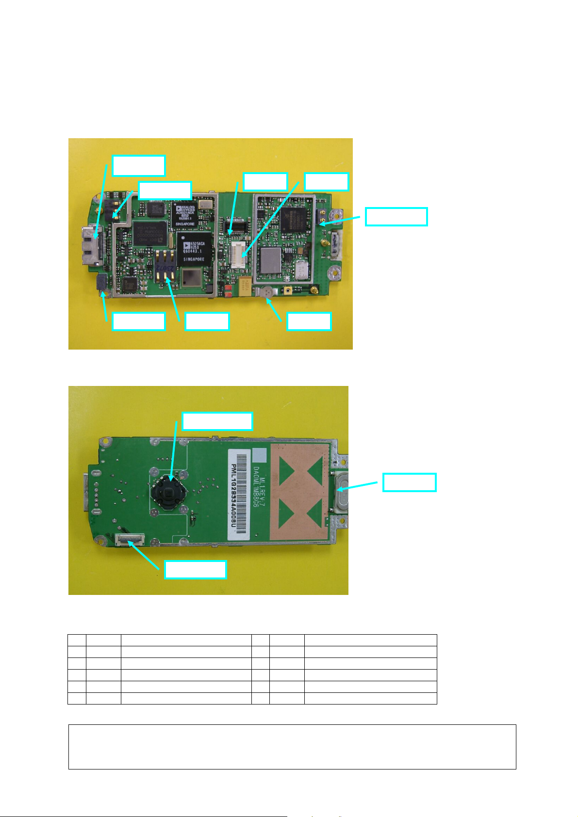
2 Repair Location Code
The front side of M/B (Connect with keys)
8. JP401
7. JP301
6. JP201 5. J101
The rear side of M/B
10. SW401
2. J503
3. J504
4. JP202
1. RTC
9. JP203
11. JP402
2.1 Code Description
1 RTC RTC 7 JP301 BATT Connector
2 J503 LCD Connector 8 JP401 IO Connector
3 J504 Camera Connector 9 JP203 Receiver
4 JP202 Speaker Spring 10 SW401 Joystick
5 J101 SIM Connector 11 JP402 Keypad Connector
6 JP201 MIC Connector
V 1.1 Page 4of 39 COM MD CC GRM T
ST55
Company Confidential
Copyright 2003© Siemens AG
01/05
s Com
3 RTC (RTC Battery)
3.1 Affected Units
Type: ST55
Affected IMEIs / Date Codes: All/All
Affected SW-Versions: All
3.2 Fault Description
Fault Symptoms for customers:
Time/Clock will reset each time power on.
No call records can be saved.
Fault Symptom on GSM-Tester:
None
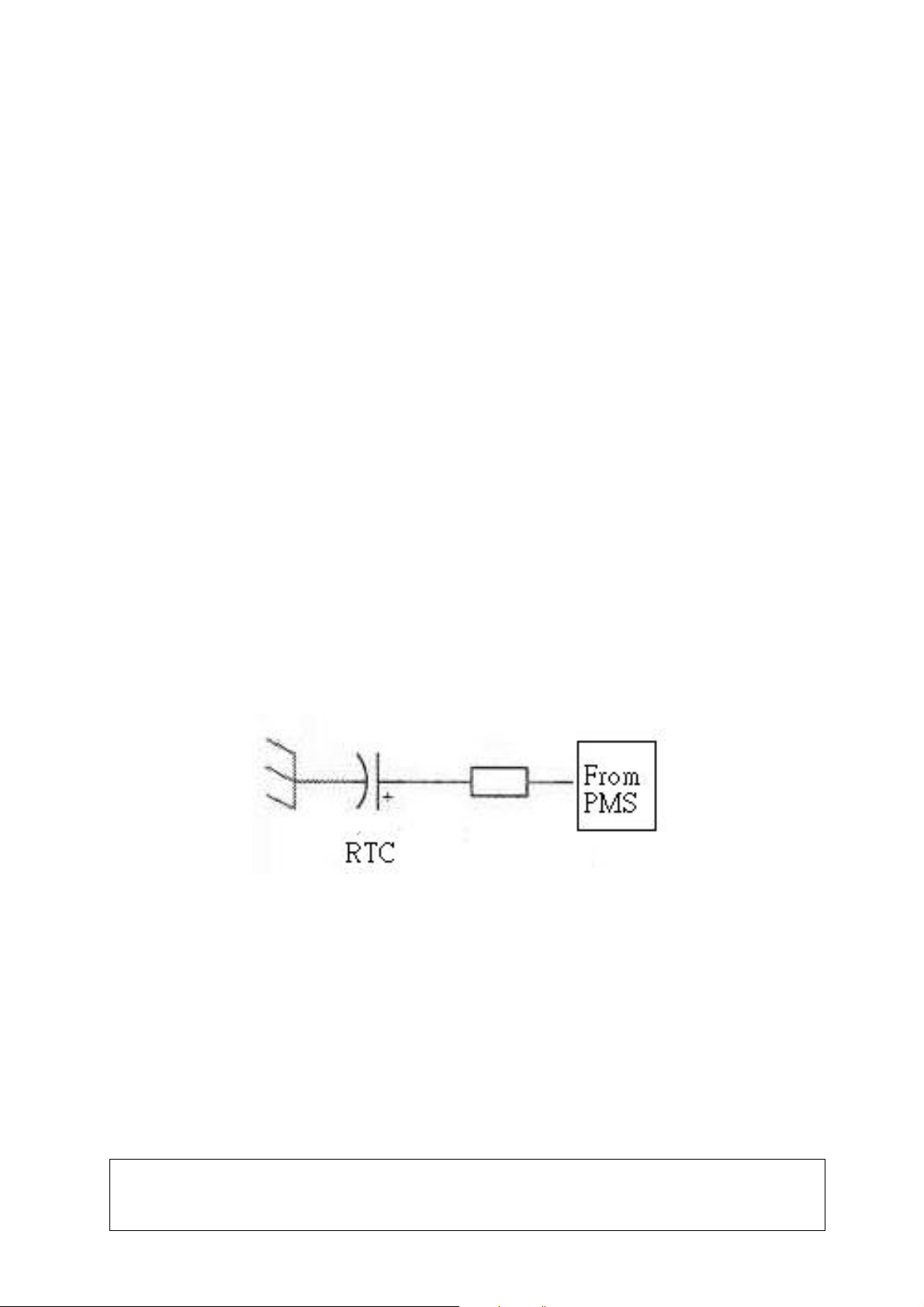
Component Information
The RTC is a capacitor that supplies the power to the system to make the real time clock go on
counting about 45minutes after the main battery of phone is taken off. Besides, the RTC battery
will always be charged from the PMS when the main battery is inside the phone. See drawing
below.
PMS: Power Management System
V 1.1 Page 5of 39 COM MD CC GRM T
ST55
Company Confidential
Copyright 2003© Siemens AG
01/05

s Com
3.3 Repair Document
Description of procedure
Diagnosis
Visual check and measure with a multimeter to detect if the RTC is oxidized or
deformed.
Repair by component change
1. Remove the defected RTC by Hot Air Blower (350°C ~ 400 °C) (350~400 °C).
2. Put on new RTC and add solder at the “+” side first.
3. Then add solder at the “-“ side.
Repair by SW-Booting
Not possible!
Test
Retest handset after repair procedure as described above
List of needed material
Components
ST55 RTC battery
Part Number: L36385-F505-X
Jigs and Tools
Hot Air Blower (350°C ~ 400 °C)
Soldering Iron (350°C ± 20 °C)
Special Tools:
Multimeter
Working materials
Desolder Wick / Braid
Solder
V 1.1 Page 6of 39 COM MD CC GRM T
ST55
Company Confidential
Copyright 2003© Siemens AG
01/05
s Com
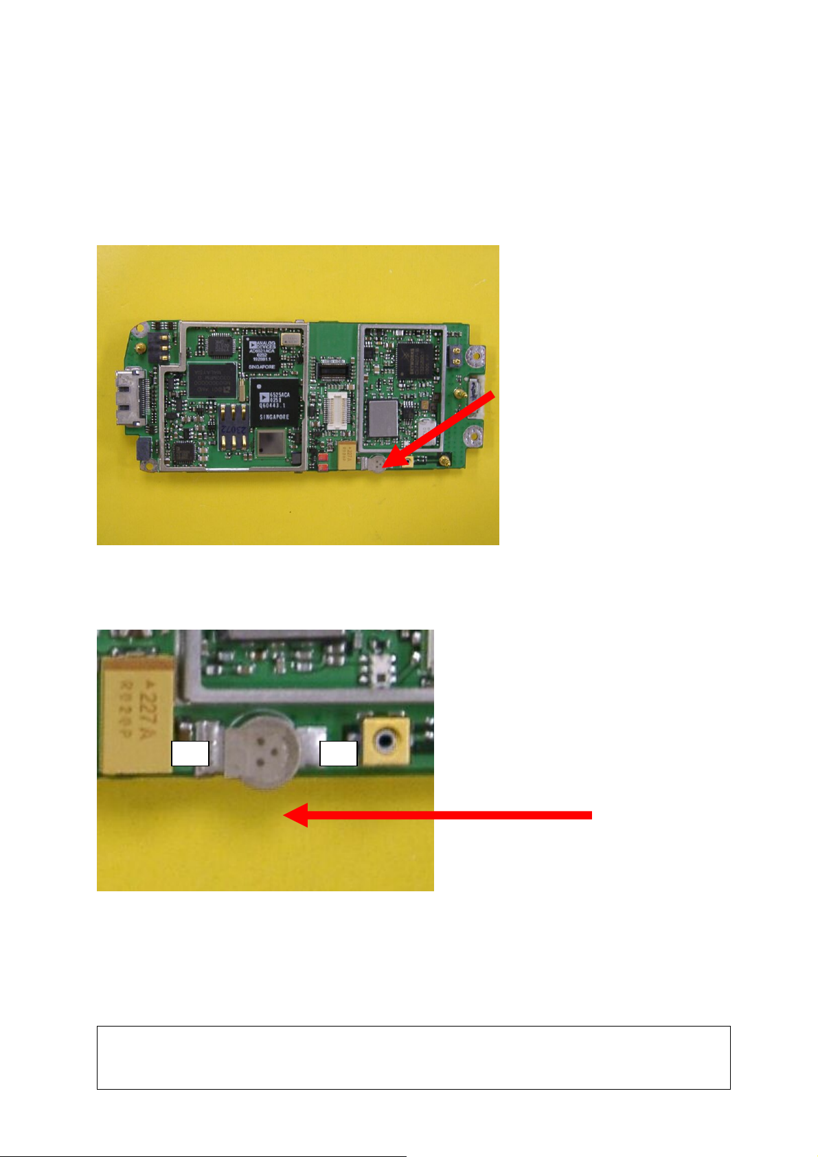
Drawings
Figure 1.1: ST55 Board RTC Side (Top View)
¨
Figure 1.2: ST55 Board RTC Placement (RTC) (Top View)
―
V 1.1 Page 7of 39 COM MD CC GRM T
ST55
Company Confidential
Copyright 2003© Siemens AG
01/05
s Com
4 LCD Connector (J503)
4.1 Affected Units
Type: ST55
Affected IMEIs / Date Codes: All/All
Affected SW-Versions: All
4.2 Fault Description
Fault Symptoms for customers:
No screen or wrong display.
Fault Symptom on GSM-Tester:
None
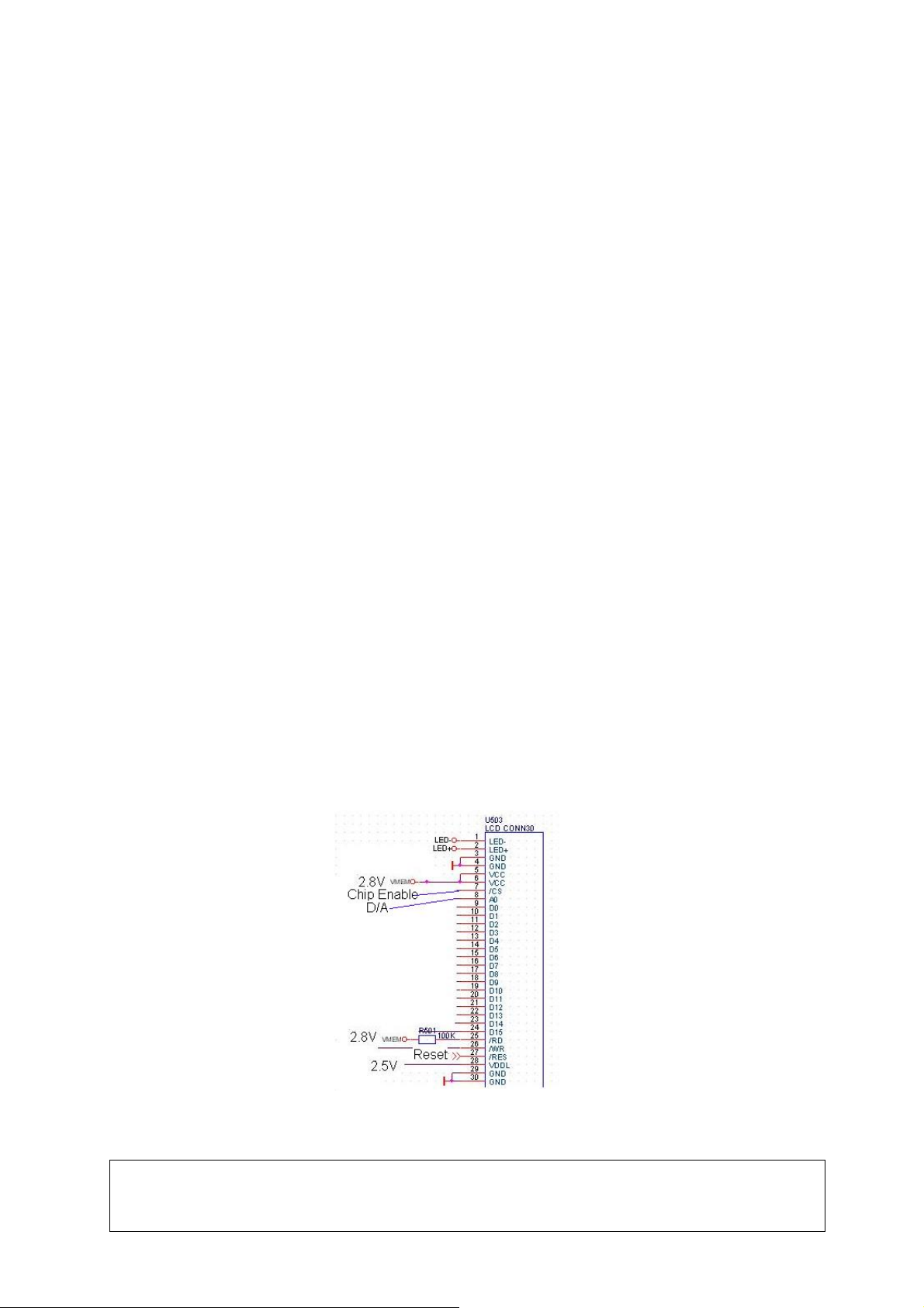
Component Information
The LCD Cable Connector is a 30-pins conta ct type socket. There are 2 type signals transmitted
through this connector.
1. LCD signal:
A2, D0~D15, WR, REST, VDD 2.8V,VDDL 2.5V are used to transmitted the add ress signal, data
signal, control signal and power signal of LCD.
2. Backlight LED signal:
There is 11V power supplied to the anode of backlight LED via D303. LCDlight - connects the
cathode of backlight LED and the resister that can limit the current passing through the LED.
V 1.1 Page 8of 39 COM MD CC GRM T
ST55
Company Confidential
Copyright 2003© Siemens AG
01/05

s Com
4.3 Repair Document
Description of procedure
Diagnosis
Visual check and measure with a multimeter to detect if pins are cold, insufficient
soldering, oxidized or deformed.
Repair by component change
1.Re-solder this connector if cold or insufficient soldering.
2.Use hot blower to remove defective connector and add solder on pads.
Avoid excessive heat! Watch surrounding component!
3.Heat and put on a new connector to enhance adhesion.
4.Re-solder new connector afterwards.
Repair by SW-Booting
Not possible!
Test
After repair procedure as described above, power on handset and chec k the display.
List of needed material
Components
ST55 LCD Connector
Part Number: L36334-Z97-C311
Jigs and Tools
Hot Air Blower (350°C ~ 400 °C)
Soldering Iron (350°C ± 20 °C)
Special Tools:
Multimeter
Working materials
Solder; Desolder Wick / Braid
V 1.1 Page 9of 39 COM MD CC GRM T
ST55
Company Confidential
Copyright 2003© Siemens AG
01/05
s Com
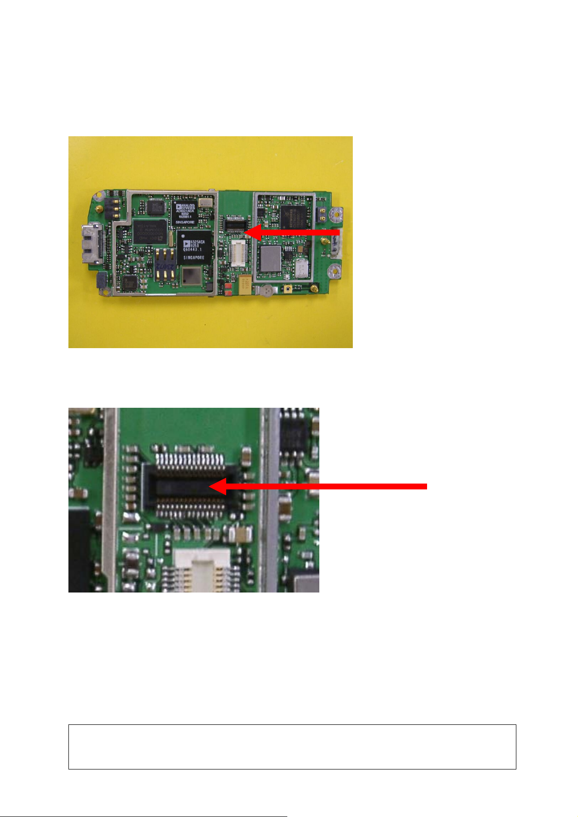
Drawings
Figure 2.1: ST55 Board LCD Connector Side (Top View)
Figure 2.2: ST55 Board LCD Connector Placement (J503) (Top View)
V 1.1 Page 10of 39 COM MD CC GRM T
ST55
Company Confidential
Copyright 2003© Siemens AG
01/05
s Com
5 Camera Connector (J504)
5.1 Affected Units
Type: ST55
Affected IMEIs / Date Codes: All/All
Affected SW-Versions: All
5.2 Fault Description
Fault Symptoms for customers:
The picture captured by camera can’t be shown on screen or abnormal display.
Fault Symptom on GSM-Tester:
None
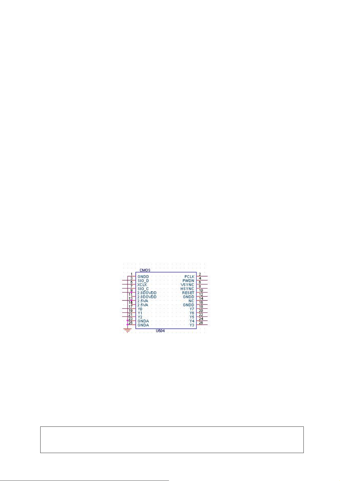
Component Information
The camera connector is a 26-pins contact type socket. It had 2 kinds of working voltage (2.8 and
2.5V), 13MHz-working frequency. Using the YUV data format.
V 1.1 Page 11of 39 COM MD CC GRM T
ST55
Company Confidential
Copyright 2003© Siemens AG
01/05

s Com
5.3 Repair Document
Description of procedure
Diagnosis
Visual check and measure with a multimeter to detect if the pins are cold, insufficient
soldering, oxidized or deformed.
Repair by component change
1.Re-solder this connector if cold or insufficient soldering.
2.Use hot blower to remove defective connector and add solder on pads.
Avoid excessive heat! Watch surrounding component!
3.Heat and put on a new connector to enhance adhesion.
4.Re-solder new connector afterwards.
Repair by SW-Booting
Not possible!
Test
After repair procedure as described above, power on handset and check the camera
function.
List of needed material
Components
ST55 Camera Connector
Part Number: L36334-Z97-C323
Jigs and Tools
Hot Air Blower (350°C ~ 400 °C) (350~400 °C)
Soldering Iron (350°C ± 20 °C)
Special Tools:
Multimeter
Working materials
Solder
V 1.1 Page 12of 39 COM MD CC GRM T
ST55
Company Confidential
Copyright 2003© Siemens AG
01/05
 Loading...