

Siemens SLIM Installation Instructions Manual

FRONT
BACK
FAULT
IN - LINE 1
IN - LINE 2
OUT - LINE 1
OUT - LINE 2
Installation Instructions
Model SLIM
Loop Isolator Module
OPERATION The Model SLIM Loop Isolator Module from Siemens Building Technologies, Ltd.
isolates short circuits on FS-250C analog loops. By placing devices between SLIMs
during installation, a short in the wiring within that group is disconnected from the
rest of the loop. The
remainder of the devices
continue to operate. The
SLIM operates in both
Class A and Class B
circuits.
A yellow LED flashes
when a device detects a
short circuit. The SLIM
then isolates that part of
the loop. When the short
is removed, the SLIM
automatically restores
the loop to normal operation. The SLIM does not have a loop address and therefore
does not require address programming nor does it reduce the loop capacity below
252 devices.
Figure 1
The SLIM-1 Loop Isolator Module
Remove all system power before installation, first the battery and then the AC.
INSTALLATION The SLIM is a polarity insensitive module. Refer to Figure 1 for the location of the two
input terminals and two output terminals. Line 1 and Line 2 can be either line of the
loop.
The SLIM may be used in two circuit configurations as follows:
Class B (See Figure 2) In Class B wiring each SLIM isolates a branch on the circuit. Note that
a short on the main branch causes the entire loop to fail. To prevent this, mount the
SLIMs at the enclosure and run each branch independently.
P/N 315-049692C-1
Siemens Building Technologies
Fire Safety
1. All wiring must comply with
national and local codes.
2. In order to provide adequate
protection, it is recommended that you do not
install more than 20 devices
ANALOG LOOP
LINE 1
LINE 2
on a single SLIM.
3. Minimum wire gauge is
18 AWG.
4. The total wire resistance
(both wires) between SLIMs
cannot exceed 20 ohms.
5. Do not install more than 15
SLIMs per FDLC loop.
6. All circuits are supervised.
7. Refer to FDLC Installation
IN IN OUT OUTIN IN OUT OUTIN IN OUT OUT
Instructions, P/N 315447360FA or the FS-250C
Manual, P/N 315-049589C
for the list of compatible
devices, as applicable.
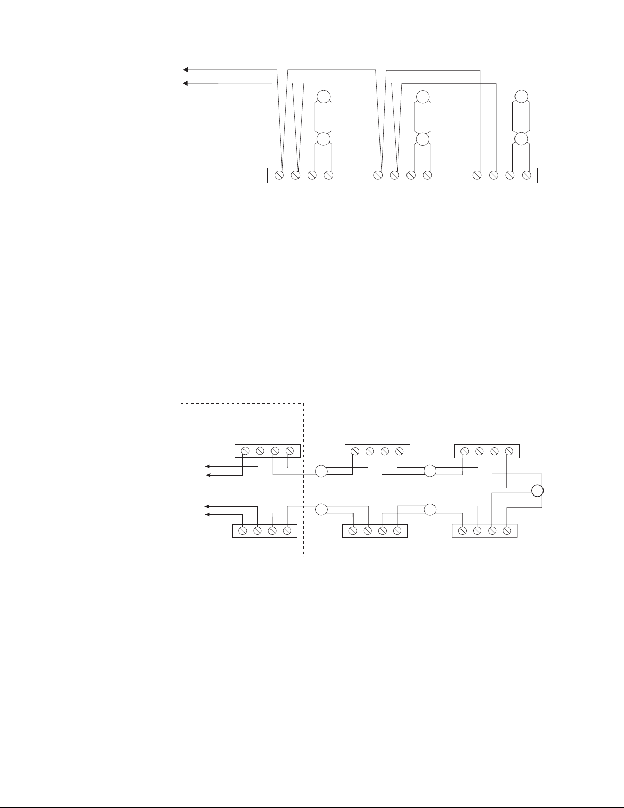
Figure 2
SLIM Wiring Diagram - Class B Installation
8. All terminals are power
limited.
Class A Single Loop (See Figure 3) In Class A wiring the SLIMs are wired in series with the loop wiring.
This results in a single continuous loop. If any group in the loop has a short, that
group is lost and a Class A circuit failure results.
1. All wiring must comply with
national and local codes.
2. In order to provide adequate
protection, it is recommended that you do not
install more than 20 devices
on a single SLIM.
3. Minimum wire gauge is
18 AWG.
4. The total wire resistance
(both wires) between SLIMs
cannot exceed 20 ohms.
5. Do not install more than 15
SLIMs per FDLC loop.
6. All circuits are supervised.
7. Refer to FDLC Installation
Instructions, P/N 315447360FA or the FS-250C
Manual, P/N 315-049589C
for the list of compatible
devices, as applicable.
8. All terminals are power
limited.
• The FS-250C displays the message “DLC Open” and “no response” for
devices in the groups on the loop that follow the short.
INSIDE ENCLOSURE
TO ANALOG
LOOP RETURN
LINE 2
LINE 1
TO ANALOG
LOOP FEED
OUTOUT
LINE 1
LINE 2
IN IN OUT OUT IN IN OUT OUT
ININ
OUTOUT
IN IN OUT OUT
ININ
OUTOUT
Figure 3
SLIM Wiring Diagram - Class A Installation (Single Loop)
ININ
Siemens Building Technologies
Fire Safety
P/N 315-049692C-12
 Loading...