

Page 1

SINUMERIK
SINUMERIK 828D, SINAMICS S120
Safety Integrated
Valid for:
CNC software Version 4.7 SP2
Preface
Function Manual
Safety instructions
Overview of Safety
Integrated functions
Commissioning - drive-based
Commissioning - TM54F
Commissioning - acceptance
tests
Commissioning - application
example
Diagnostics
1
2
3
4
5
6
7
System Features
Standards and specifications
Appendix
8
9
A
10/2015
6FC5397-3EP40-5BA3
Page 2

Legal information
Warning notice system
This manual contains notices you have to observe in order to ensure your personal safety, as well as to prevent
damage to property. The notices referring to your personal safety are highlighted in the manual by a safety alert
symbol, notices referring only to property damage have no safety alert symbol. These notices shown below are
graded according to the degree of danger.
DANGER
indicates that death or severe personal injury will result if proper precautions are not taken.
WARNING
indicates that death or severe personal injury may result if proper precautions are not taken.
CAUTION
indicates that minor personal injury can result if proper precautions are not taken.
NOTICE
indicates that property damage can result if proper precautions are not taken.
If more than one degree of danger is present, the warning notice representing the highest degree of danger will be
used. A notice warning of injury to persons with a safety alert symbol may also include a warning relating to property
damage.
Qualified Personnel
The product/system described in this documentation may be operated only by personnel qualified for the specific
task in accordance with the relevant documentation, in particular its warning notices and safety instructions. Qualified
personnel are those who, based on their training and experience, are capable of identifying risks and avoiding
potential hazards when working with these products/systems.
Proper use of Siemens products
Note the following:
WARNING
Siemens products may only be used for the applications described in the catalog and in the relevant technical
documentation. If products and components from other manufacturers are used, these must be recommended or
approved by Siemens. Proper transport, storage, installation, assembly, commissioning, operation and
maintenance are required to ensure that the products operate safely and without any problems. The permissible
ambient conditions must be complied with. The information in the relevant documentation must be observed.
Trademarks
All names identified by ® are registered trademarks of Siemens AG. The remaining trademarks in this publication
may be trademarks whose use by third parties for their own purposes could violate the rights of the owner.
Disclaimer of Liability
We have reviewed the contents of this publication to ensure consistency with the hardware and software described.
Since variance cannot be precluded entirely, we cannot guarantee full consistency. However, the information in
this publication is reviewed regularly and any necessary corrections are included in subsequent editions.
Siemens AG
Division Digital Factory
Postfach 48 48
90026 NÜRNBERG
GERMANY
Order number: 6FC5397-3EP40-5BA3
Ⓟ 11/2015 Subject to change
Copyright © Siemens AG 2012 - 2015.
All rights reserved
Page 3

Preface
SINUMERIK documentation
The SINUMERIK documentation is organized in the following categories:
● General documentation
● User documentation
● Manufacturer/service documentation
Additional information
You can find information on the following topics under the link (
motioncontrol/docu):
● Ordering documentation/overview of documentation
● Additional links to download documents
● Using documentation online (find and search in manuals/information)
Please send any questions about the technical documentation (e.g. suggestions for
improvement, corrections) to the following address:
(mailto:docu.motioncontrol@siemens.com)
My Documentation Manager (MDM)
Under the following link you will find information to individually compile OEM-specific machine
documentation based on the Siemens content: MDM (www.siemens.com/mdm)
Training
For information about the range of training courses, refer under:
● SITRAIN (www.siemens.com/sitrain) - training courses from Siemens for automation
products, systems and solutions
● SinuTrain (www.siemens.com/sinutrain) - training software for SINUMERIK
www.siemens.com/
FAQs
You can find Frequently Asked Questions in the Service&Support pages under Product
Support (www.siemens.com/automation/service&support).
Safety Integrated
Function Manual, 10/2015, 6FC5397-3EP40-5BA3 3
Page 4

Preface
SINUMERIK
Target group
Benefits
Standard version
You can find information on SINUMERIK under the following link: (
sinumerik)
Project engineers, technologists (of the machine manufacturers), commissioning engineers
(for systems or machines), and programmers.
The function manual describes the functions so that the target group knows them and can
select them. It provides the target group with the information required to implement the
functions.
Planning and configuration phase, implementation phase, setup and commissioning phase.
This documentation only describes the functionality of the standard version. Extensions or
changes made by the machine manufacturer are documented by the machine manufacturer.
Other functions not described in this documentation might be executable in the control. This
does not, however, represent an obligation to supply such functions with a new control or when
servicing.
www.siemens.com/
Further, for the sake of simplicity, this documentation does not contain all detailed information
about all types of the product and cannot cover every conceivable case of installation, operation
or maintenance.
Technical Support
Country-specific telephone numbers for technical support are provided in the Internet under
"Contact" (www.siemens.com/automation/service&support).
EC Declaration of Conformity
The EC declaration of conformity for the EMC directive can be found in the Internet
(www.siemens.com/automation/service&support).
There, as search term, enter the number 15257461 or contact your local Siemens office.
Safety Integrated
4 Function Manual, 10/2015, 6FC5397-3EP40-5BA3
Page 5

Table of contents
Preface.........................................................................................................................................................3
1 Safety instructions........................................................................................................................................9
1.1 Fundamental safety instructions..............................................................................................9
1.1.1 General safety instructions.......................................................................................................9
1.1.2 Handling electrostatic sensitive devices (ESD)......................................................................12
1.1.3 Industrial security...................................................................................................................13
1.1.4 Residual risks of power drive systems...................................................................................13
1.2 Safety Integrated safety instructions......................................................................................16
1.3 Probability of failure of the safety functions............................................................................19
1.4 Residual risk...........................................................................................................................20
2 Overview of Safety Integrated functions.....................................................................................................23
2.1 Supported functions...............................................................................................................24
2.2 Safety Integrated Basic Functions.........................................................................................27
2.2.1 Safe Torque Off (STO)...........................................................................................................27
2.2.2 Safe Stop 1 (SS1)..................................................................................................................28
2.2.3 Safe Brake Control (SBC)......................................................................................................29
2.3 Safety Integrated Extended Functions...................................................................................30
2.3.1 Safe Torque Off (STO)...........................................................................................................30
2.3.2 Safe Stop 1 (SS1)..................................................................................................................30
2.3.3 Safe Brake Control (SBC)......................................................................................................32
2.3.4 Safe Operating Stop (SOS)....................................................................................................33
2.3.5 Safe Stop 2 (SS2)..................................................................................................................34
2.3.6 Safely Limited Speed (SLS)...................................................................................................36
2.3.7 Safe Speed Monitor (SSM)....................................................................................................40
2.3.8 Safe Direction (SDI)...............................................................................................................42
2.3.9 Safely-Limited Position (SLP)................................................................................................44
2.3.10 Safe Brake Test (SBT)...........................................................................................................45
3 Commissioning - drive-based.....................................................................................................................47
3.1 Introduction............................................................................................................................47
3.2 Activating the commissioning mode.......................................................................................49
3.3 Canceling the commissioning mode......................................................................................51
3.4 Exit the commissioning mode................................................................................................52
3.5 Copying or confirming SI data................................................................................................54
3.6 Working with parameter lists..................................................................................................56
3.7 Safety overview......................................................................................................................57
3.7.1 Calling the overview and detailed views................................................................................57
3.7.2 Safety Integrated overview.....................................................................................................58
3.7.3 Safety Integrated overview - details.......................................................................................59
Safety Integrated
Function Manual, 10/2015, 6FC5397-3EP40-5BA3 5
Page 6

Table of contents
3.7.4 Safety Integrated overview - checksums...............................................................................60
3.8 Making the basic safety settings............................................................................................62
3.8.1 Calling the basic setting dialog...............................................................................................62
3.8.2 Options...................................................................................................................................64
3.8.3 Configuration..........................................................................................................................66
3.8.4 Encoder parameterization......................................................................................................67
3.8.5 Telegram configuration..........................................................................................................70
3.9 Safety Integrated functions....................................................................................................71
3.9.1 Calling function dialogs..........................................................................................................71
3.9.2 Safe Torque Off (STO)/Safe Stop 1 (SS1) - basis function....................................................72
3.9.3 Safe Torque Off (STO) - extended function...........................................................................73
3.9.4 Safe Brake Control (SBC)......................................................................................................75
3.9.5 Safe Stop 1 (SS1) Extended Function...................................................................................77
3.9.6 Safe Stop 2 (SS2)/Safe Operating Stop (SOS)......................................................................78
3.9.7 Safely Limited Speed (SLS)...................................................................................................80
3.9.8 Safe Speed Monitor (SSM)....................................................................................................81
3.9.9 Safe Acceleration Monitor (SAM)...........................................................................................83
3.9.10 Safe Direction (SDI)...............................................................................................................84
3.9.11 Safely Limited Position (SLP).................................................................................................85
3.9.12 Safe Brake Test (SBT)...........................................................................................................88
4 Commissioning - TM54F............................................................................................................................93
4.1 Introduction............................................................................................................................93
4.2 Activating the commissioning mode.......................................................................................95
4.3 Canceling the commissioning mode......................................................................................97
4.4 Exit the commissioning mode................................................................................................99
4.5 Configuring the TM54F........................................................................................................102
4.5.1 Calling the configuration range............................................................................................102
4.5.2 Configuration........................................................................................................................103
4.5.3 Inputs...................................................................................................................................105
4.5.4 Outputs.................................................................................................................................106
4.5.5 Drive groups.........................................................................................................................108
4.5.6 Working with parameter lists................................................................................................110
4.5.7 TM54F checksums...............................................................................................................111
5 Commissioning - acceptance tests...........................................................................................................113
5.1 Introduction..........................................................................................................................113
5.2 Content of the complete acceptance test.............................................................................115
5.3 Sequence of an acceptance test..........................................................................................119
5.3.1 Calling an acceptance test...................................................................................................119
5.3.2 Setting areas of the acceptance test....................................................................................120
5.3.3 Configuring and performing an acceptance test..................................................................126
6 Commissioning - application example......................................................................................................133
6.1 Planning...............................................................................................................................133
6.1.1 Creating a function table......................................................................................................133
6.1.2 From the function table to the logic diagram........................................................................134
6.2 Preconditions for commissioning.........................................................................................137
Safety Integrated
6 Function Manual, 10/2015, 6FC5397-3EP40-5BA3
Page 7

Table of contents
6.3 Parameterizing the TM54F...................................................................................................139
6.3.1 Configuring the drive groups................................................................................................139
6.3.2 Connecting safe outputs......................................................................................................142
6.3.3 TM54F terminal description..................................................................................................144
6.4 Controlling with the SIRIUS 3SK or SIRIUS 3RK relay........................................................146
6.4.1 Controlling the TM54F with SIRIUS 3SK.............................................................................146
6.4.2 Control of the TM54F with SIRIUS 3RK...............................................................................151
6.5 Configuration of the SI functions for the drive......................................................................154
6.5.1 Activating Safety Integrated.................................................................................................154
6.5.2 Encoder parameterization....................................................................................................156
6.5.3 Setting parameters SLS1-4, SBC, SS1, SS2.......................................................................158
6.6 SINUMERIK 828D control system.......................................................................................160
6.6.1 SIC/SCC interface................................................................................................................160
7 Diagnostics...............................................................................................................................................161
7.1 Calling diagnostic views.......................................................................................................161
7.2 Safety Integrated diagnostics overview................................................................................163
7.3 Safety Integrated drives.......................................................................................................164
7.3.1 Basic functions.....................................................................................................................164
7.3.2 Extended functions...............................................................................................................165
7.4 TM54F..................................................................................................................................167
7.4.1 Configuration........................................................................................................................167
7.4.2 Inputs...................................................................................................................................168
7.4.3 Outputs.................................................................................................................................169
7.4.4 Drive groups.........................................................................................................................171
7.5 Safety Integrated checksums...............................................................................................173
7.5.1 Safety Integrated checksum.................................................................................................173
7.5.2 Safety Integrated global checksums....................................................................................174
7.5.3 TM54F checksums...............................................................................................................175
7.5.4 Drive checksums..................................................................................................................177
7.6 Safety Integrated alarms......................................................................................................179
7.7 Acknowledging hardware replacement................................................................................180
8 System Features......................................................................................................................................183
8.1 Latest information.................................................................................................................183
8.2 Certifications........................................................................................................................185
9 Standards and specifications....................................................................................................................187
9.1 General................................................................................................................................187
9.2 Safety of machinery in Europe.............................................................................................189
9.2.1 Safety of machinery in Europe.............................................................................................189
9.2.2 Harmonized European Standards........................................................................................189
9.3 Machine safety in the USA...................................................................................................191
9.3.1 Machine safety in the USA...................................................................................................191
9.3.2 Minimum requirements of the OSHA...................................................................................191
9.3.3 NRTL listing..........................................................................................................................192
Safety Integrated
Function Manual, 10/2015, 6FC5397-3EP40-5BA3 7
Page 8

Table of contents
9.3.4 NFPA 79...............................................................................................................................192
9.3.5 ANSI B11.............................................................................................................................193
9.4 Machine safety in Japan......................................................................................................194
9.4.1 Machine safety in Japan......................................................................................................194
9.5 Equipment regulations.........................................................................................................195
9.5.1 Equipment regulations.........................................................................................................195
9.6 Other safety-related issues..................................................................................................196
9.6.1 Information sheets issued by the Employer's Liability Insurance Association......................196
9.6.2 Additional references...........................................................................................................196
A Appendix...................................................................................................................................................197
A.1 Abbreviations.......................................................................................................................197
A.2 Documentation overview SINUMERIK 828D.......................................................................200
Index.........................................................................................................................................................201
Safety Integrated
8 Function Manual, 10/2015, 6FC5397-3EP40-5BA3
Page 9
Safety instructions
1.1 Fundamental safety instructions
1.1.1 General safety instructions
DANGER
Danger to life due to live parts and other energy sources
Death or serious injury can result when live parts are touched.
● Only work on electrical devices when you are qualified for this job.
● Always observe the country-specific safety rules.
Generally, six steps apply when establishing safety:
1. Prepare for shutdown and notify all those who will be affected by the procedure.
2. Disconnect the machine from the supply.
– Switch off the machine.
– Wait until the discharge time specified on the warning labels has elapsed.
– Check that it really is in a no-voltage condition, from phase conductor to phase
conductor and phase conductor to protective conductor.
– Check whether the existing auxiliary supply circuits are de-energized.
– Ensure that the motors cannot move.
3. Identify all other dangerous energy sources, e.g. compressed air, hydraulic systems, or
water.
4. Isolate or neutralize all hazardous energy sources by closing switches, grounding or shortcircuiting or closing valves, for example.
5. Secure the energy sources against switching on again.
6. Ensure that the correct machine is completely interlocked.
1
After you have completed the work, restore the operational readiness in the inverse sequence.
WARNING
Danger to life through a hazardous voltage when connecting an unsuitable power supply
Touching live components can result in death or severe injury.
● Only use power supplies that provide SELV (Safety Extra Low Voltage) or PELV-
(Protective Extra Low Voltage) output voltages for all connections and terminals of the
electronics modules.
Safety Integrated
Function Manual, 10/2015, 6FC5397-3EP40-5BA3 9
Page 10
Safety instructions
1.1 Fundamental safety instructions
WARNING
Danger to life when live parts are touched on damaged devices
Improper handling of devices can cause damage.
For damaged devices, hazardous voltages can be present at the enclosure or at exposed
components; if touched, this can result in death or severe injury.
● Ensure compliance with the limit values specified in the technical data during transport,
storage and operation.
● Do not use any damaged devices.
WARNING
Danger to life through electric shock due to unconnected cable shields
Hazardous touch voltages can occur through capacitive cross-coupling due to unconnected
cable shields.
● As a minimum, connect cable shields and the cores of cables that are not used at one end
at the grounded housing potential.
WARNING
Danger to life due to electric shock when not grounded
For missing or incorrectly implemented protective conductor connection for devices with
protection class I, high voltages can be present at open, exposed parts, which when touched,
can result in death or severe injury.
● Ground the device in compliance with the applicable regulations.
WARNING
Danger to life due to fire spreading if housing is inadequate
Fire and smoke development can cause severe personal injury or material damage.
● Install devices without a protective housing in a metal control cabinet (or protect the device
by another equivalent measure) in such a way that contact with fire is prevented.
● Ensure that smoke can only escape via controlled and monitored paths.
Safety Integrated
10 Function Manual, 10/2015, 6FC5397-3EP40-5BA3
Page 11
Safety instructions
1.1 Fundamental safety instructions
WARNING
Danger to life through unexpected movement of machines when using mobile wireless
devices or mobile phones
Using mobile wireless devices or mobile phones with a transmit power > 1 W closer than
approx. 2 m to the components may cause the devices to malfunction, influence the functional
safety of machines therefore putting people at risk or causing material damage.
● Switch the wireless devices or mobile phones off in the immediate vicinity of the
components.
WARNING
Danger to life due to fire if overheating occurs because of insufficient ventilation clearances
Inadequate ventilation clearances can cause overheating of components with subsequent
fire and smoke. This can cause severe injury or even death. This can also result in increased
downtime and reduced service lives for devices/systems.
● Ensure compliance with the specified minimum clearance as ventilation clearance for the
respective component.
WARNING
Danger to life when safety functions are inactive
Safety functions that are inactive or that have not been adjusted accordingly can cause
operational faults on machines that could lead to serious injury or death.
● Observe the information in the appropriate product documentation before commissioning.
● Carry out a safety inspection for functions relevant to safety on the entire system, including
all safety-related components.
● Ensure that the safety functions used in your drives and automation tasks are adjusted
and activated through appropriate parameterizing.
● Perform a function test.
● Only put your plant into live operation once you have guaranteed that the functions relevant
to safety are running correctly.
Note
Important safety notices for Safety Integrated functions
If you want to use Safety Integrated functions, you must observe the safety notices in the Safety
Integrated manuals.
Safety Integrated
Function Manual, 10/2015, 6FC5397-3EP40-5BA3 11
Page 12
Safety instructions
1.1 Fundamental safety instructions
WARNING
Danger to life or malfunctions of the machine as a result of incorrect or changed
parameterization
As a result of incorrect or changed parameterization, machines can malfunction, which in turn
can lead to injuries or death.
● Protect the parameterization (parameter assignments) against unauthorized access.
● Respond to possible malfunctions by applying suitable measures (e.g. EMERGENCY
STOP or EMERGENCY OFF).
1.1.2 Handling electrostatic sensitive devices (ESD)
Electrostatic sensitive devices (ESD) are individual components, integrated circuits, modules
or devices that may be damaged by either electric fields or electrostatic discharge.
NOTICE
Damage through electric fields or electrostatic discharge
Electric fields or electrostatic discharge can cause malfunctions through damaged individual
components, integrated circuits, modules or devices.
● Only pack, store, transport and send electronic components, modules or devices in their
original packaging or in other suitable materials, e.g conductive foam rubber of aluminum
foil.
● Only touch components, modules and devices when you are grounded by one of the
following methods:
– Wearing an ESD wrist strap
– Wearing ESD shoes or ESD grounding straps in ESD areas with conductive flooring
● Only place electronic components, modules or devices on conductive surfaces (table with
ESD surface, conductive ESD foam, ESD packaging, ESD transport container).
Safety Integrated
12 Function Manual, 10/2015, 6FC5397-3EP40-5BA3
Page 13
1.1.3 Industrial security
Note
Industrial security
Siemens provides products and solutions with industrial security functions that support the
secure operation of plants, solutions, machines, equipment and/or networks. They are
important components in a holistic industrial security concept. With this in mind, Siemens’
products and solutions undergo continuous development. Siemens recommends strongly that
you regularly check for product updates.
For the secure operation of Siemens products and solutions, it is necessary to take suitable
preventive action (e.g. cell protection concept) and integrate each component into a holistic,
state-of-the-art industrial security concept. Third-party products that may be in use should also
be considered. For more information about industrial security, visit this address (http://
www.siemens.com/industrialsecurity).
To stay informed about product updates as they occur, sign up for a product-specific
newsletter. For more information, visit this address (http://support.automation.siemens.com).
Safety instructions
1.1 Fundamental safety instructions
WARNING
Danger as a result of unsafe operating states resulting from software manipulation
Software manipulation (e.g. by viruses, Trojan horses, malware, worms) can cause unsafe
operating states to develop in your installation which can result in death, severe injuries and/
or material damage.
● Keep the software up to date.
You will find relevant information and newsletters at this address (http://
support.automation.siemens.com).
● Incorporate the automation and drive components into a holistic, state-of-the-art industrial
security concept for the installation or machine.
You will find further information at this address (http://www.siemens.com/
industrialsecurity).
● Make sure that you include all installed products into the holistic industrial security concept.
1.1.4 Residual risks of power drive systems
The control and drive components of a drive system are approved for industrial and commercial
use in industrial line supplies. Their use in public line supplies requires a different configuration
and/or additional measures.
These components may only be operated in closed housings or in higher-level control cabinets
with protective covers that are closed, and when all of the protective devices are used.
These components may only be handled by qualified and trained technical personnel who are
knowledgeable and observe all of the safety instructions on the components and in the
associated technical user documentation.
Safety Integrated
Function Manual, 10/2015, 6FC5397-3EP40-5BA3 13
Page 14

Safety instructions
1.1 Fundamental safety instructions
When assessing the machine's risk in accordance with the respective local regulations (e.g.,
EC Machinery Directive), the machine manufacturer must take into account the following
residual risks emanating from the control and drive components of a drive system:
1. Unintentional movements of driven machine components during commissioning, operation,
maintenance, and repairs caused by, for example,
– Hardware and/or software errors in the sensors, control system, actuators, and cables
and connections
– Response times of the control system and of the drive
– Operation and/or environmental conditions outside the specification
– Condensation/conductive contamination
– Parameterization, programming, cabling, and installation errors
– Use of wireless devices/mobile phones in the immediate vicinity of the control system
– External influences/damage
2. In the event of a fault, exceptionally high temperatures, including an open fire, as well as
emissions of light, noise, particles, gases, etc. can occur inside and outside the inverter,
e.g.:
– Component failure
– Software errors
– Operation and/or environmental conditions outside the specification
– External influences/damage
Inverters of the Open Type/IP20 degree of protection must be installed in a metal control
cabinet (or protected by another equivalent measure) such that contact with fire inside and
outside the inverter is not possible.
3. Hazardous shock voltages caused by, for example,
– Component failure
– Influence during electrostatic charging
– Induction of voltages in moving motors
– Operation and/or environmental conditions outside the specification
– Condensation/conductive contamination
– External influences/damage
4. Electrical, magnetic and electromagnetic fields generated in operation that can pose a risk
to people with a pacemaker, implants or metal replacement joints, etc., if they are too close
5. Release of environmental pollutants or emissions as a result of improper operation of the
system and/or failure to dispose of components safely and correctly
Safety Integrated
14 Function Manual, 10/2015, 6FC5397-3EP40-5BA3
Page 15

Safety instructions
1.1 Fundamental safety instructions
Note
The components must be protected against conductive contamination (e.g. by installing them
in a control cabinet with degree of protection IP54 according to IEC 60529 or NEMA 12).
Assuming that conductive contamination at the installation site can definitely be excluded, a
lower degree of cabinet protection may be permitted.
For more information about residual risks of the components in a drive system, see the relevant
sections in the technical user documentation.
Safety Integrated
Function Manual, 10/2015, 6FC5397-3EP40-5BA3 15
Page 16
Safety instructions
1.2 Safety Integrated safety instructions
1.2 Safety Integrated safety instructions
Additional safety instructions and residual risks
Additional safety information and residual risks not specified in this section are included in the
relevant sections of this Function Manual.
DANGER
Risk minimization through Safety Integrated
Safety Integrated can be used to minimize the level of risk associated with machines and
plants.
However, safe operation of a system or machine based on Safety Integrated is only possible
if the following preconditions are fully satisfied:
● The machine builder (OEM) precisely knows and observes this technical user
documentation - including the documented limitations, safety information and residual
risks.
● The machine builder (OEM) carefully and professionally designs, constructs and
configures the system/machine. This must then be verified through careful and thorough
acceptance tests by qualified personnel and the results documented.
● The machine builder (OEM) implements and validates all the measures required in
accordance with the system/machine risk analysis by means of the programmed and
configured Safety Integrated functions or by other means.
The use of Safety Integrated does not replace the machine/plant risk assessment carried out
by the machine manufacturer as required by the EC machinery directive.
In addition to using Safety Integrated functions, further risk reduction measures must be
implemented.
WARNING
Danger to life as a result of inactive Safety Integrated functions while powering up
The Safety Integrated functions are only activated after the system has completely powered
up. System startup is a critical operating state with increased risk. When accidents occur, this
can result in death or severe injury.
● Stay completely away from any hazardous areas while the system powers up.
● For vertical axes, check that the drives are in a no-torque state.
WARNING
Regulations from EN 60204-1
The Emergency Stop function must bring the machine to a standstill according to stop
category 0 or 1 (STO or SS1).
The machine must not restart automatically after EMERGENCY STOP.
When individual safety functions (Extended Functions) are deactivated, an automatic restart
is permitted under certain circumstances depending on the risk analysis (except when
Emergency Stop is reset). An automatic start is permitted when a protective door is closed,
for example.
Safety Integrated
16 Function Manual, 10/2015, 6FC5397-3EP40-5BA3
Page 17

Safety instructions
1.2 Safety Integrated safety instructions
WARNING
Danger to life when the system powers up after hardware and/or software has been changed
or replaced
After hardware and/or software components have been modified or replaced, it is only
permissible for the system to run up and the drives to be activated with the protective devices
closed. Changes to the system that have not been thoroughly tested can initiate undesirable
functions. For persons in the hazardous area, this can result in death or severe injury.
● Carry out the following tests after a change or replacement (see ChapterAcceptance test
(Page 113)):
– A complete acceptance test
– A partial acceptance test
– A simplified function test
● Before personnel may re-enter the hazardous area, the drives MUST be tested to ensure
that they exhibit stable control behavior by briefly moving them in both the plus and minus
directions (+/–).
● Ensure that nobody is in the hazardous area during the test.
● When switching on, carefully observe that Safety Integrated functions are only available
and can only be selected after the system has completely powered up.
WARNING
Danger to life when the drive coasts down for an STO or STOP A
The Category 0 stop function in accordance with EN 60204-1 (STO or STOP A acc. to Safety
Integrated) means that the drives are not actively braked. They coast to a stop (this may take
some time depending on the level of kinetic energy involved). In the case of a fault
(malfunction), this can result in death or severe injury.
● Carefully take this response into account when designing the protective door interlocking
logic.
WARNING
Danger to life as a result of a malfunction due to an acceptance test that has not been carried
out after changes to parameters have been made
Safety Integrated functions cannot detect parameter changes made by the machine builder
(OEM). Incorrect parameter changes for SI functions can result in accidents leading to death
or severe injury.
● After making a change to a parameter, always carry out an acceptance test and document
the values in an acceptance report.
● Only use the system or machine after the acceptance test has been successfully
completed.
Safety Integrated
Function Manual, 10/2015, 6FC5397-3EP40-5BA3 17
Page 18

Safety instructions
1.2 Safety Integrated safety instructions
WARNING
Danger to life as a result of different responses of the Safety Integrated functions when
replacing a Motor Module or a motor
Motor Modules or the motor must be replaced with a device of the same type, as the parameter
settings will otherwise lead to an incorrect response of the Safety Integrated functions.
Functionality that has been modified can result in accidents leading to death or severe injury.
● Always replace a component by an identical component of precisely the same type.
● Recalibrate and carefully test the drive involved when replacing an encoder.
● Carefully test the functionality after replacement.
WARNING
Danger to life as a result of parameterized safety functions, which are only available to a
restricted extent, when an internal or external fault occurs
If an internal or external fault occurs, none or only some of the parameterized safety functions
are available during the STOP F response triggered by the fault. In the case of a fault
(malfunction), this can result in death or severe injury.
● Carefully take this into account when parameterizing a delay time between STOP F and
STOP B. This is especially true for vertical axes.
Safety Integrated
18 Function Manual, 10/2015, 6FC5397-3EP40-5BA3
Page 19

1.3 Probability of failure of the safety functions
1.3 Probability of failure of the safety functions
The probability of failure of safety functions must be specified in the form of a PFH value
(Probability of Failure per Hour) according to IEC 61508, IEC 62061 and DIN EN ISO 13849-1.
The PFH value of a safety function depends on the safety concept of the control system and
the drive device, its hardware configuration and the PFH values of the components used to
implement a safety function.
For the SINUMERIK 828 and the SINAMICS S120 drive device, PFH values are made
available depending on the hardware configuration (number of drives, control type, number of
encoders used). The various integrated safety functions are not differentiated.
● The PFH values of the individual safety components of SINUMERIK 828 and
SINAMICS S120 are available in theInternet (https://support.industry.siemens.com/cs/
document/76254308?lc=en-WW).
● The PFH values of all safety components from Siemens are available in the Safety
Evaluation Tool (http://www.industry.siemens.com/topics/global/en/safety-integrated/
machine-safety/safety-evaluation-tool/Pages/default.aspx).
Safety instructions
Safety Integrated
Function Manual, 10/2015, 6FC5397-3EP40-5BA3 19
Page 20
Safety instructions
1.4 Residual risk
1.4 Residual risk
The fault analysis enables machine manufacturers to determine the residual risk at their
machine with regard to the drive unit. The following residual risks are known:
WARNING
Danger to life as a result of hardware faults relating to the intrinsic principle: PFH value
Due to the intrinsic potential of hardware faults, electrical systems are subject to additional
residual risk, which can be expressed by means of the PFH value.
● Take into account these residual risks when designing your machine and where necessary
apply suitable countermeasures.
WARNING
Danger to life when a drive accelerates in an uncontrolled fashion
Faults in the absolute track (C-D track), cyclic interchange of the drive phases (V-W-U instead
of U-V-W) and reversal of the control direction may cause acceleration of the drive. Category
1 and 2 stop functions according to EN 60204-1 (fault response functions Stop B to D
according to Safety Integrated) that are provided are however not effective due to the fault.
● Category 0 stop function according to EN 60204-1 (fault response function Stop A
according to Safety Integrated) is not activated until the transition or delay time set in the
parameter has expired. These faults are detected when SAM is selected (fault reaction
functions STOP B/C) and stop function category 0 according to EN 60204-1 (fault reaction
function STOP A according to Safety Integrated) is triggered as early as possible
regardless of this delay. Electrical faults (defective components or similar) may also lead
to the response stated above.
WARNING
Danger to life when a drive moves when two power transistors simultaneously fail (breakdown
of depletion layer)
The simultaneous breakdown of depletion layer of 2 power transistors (one in the upper and
the other offset in the lower inverter bridge) in the inverter may cause the drive to move briefly.
This can result in accidents leading to death or severe injury.
● Take suitable measures to prevent unexpected drive movement, for example, by using a
brake equipped with safety monitoring (Safe Brake Control).
WARNING
Danger to life as a result of brief, higher speeds when limit values are violated
Violation of limits may briefly lead to a speed higher than the speed setpoint, or the axis may
pass the defined position to a certain extent, depending on the dynamic response of the drive
and on parameter settings. When accidents occur, this can result in death or severe injury.
● Take into account this situation when designing your machine and where necessary apply
suitable countermeasures.
Safety Integrated
20 Function Manual, 10/2015, 6FC5397-3EP40-5BA3
Page 21

Safety instructions
1.4 Residual risk
WARNING
Residual risk for a single-encoder system
Within a single-encoder system:
a) A single electrical fault in the encoder
b) A break of the encoder shaft (or loose encoder shaft coupling), or a loose encoder housing
will cause the encoder signals to remain static (that is, they no longer follow a movement
while still returning a correct level), and prevent fault detection while the drive is in stop state
(for example, drive in SOS state).
Generally, the drive is held by the active closed-loop control. Especially for drives with
suspended load, from a closed-loop control perspective, it is conceivable that drives such as
these move without this being detected.
The risk of an electrical fault in the encoder as described under a) is only present for few
encoder types employing a specific principal of operation.
● All of the faults described above must be included in the risk analysis of the machine
manufacturer. Additional safety measures have to be taken for drives with suspended/
vertical or pulling loads - e.g. in order to exclude faults under a):
– Use of an encoder with analog signal generation
– Use of a two-encoder system
● In order to exclude the fault described in b), for example:
– Perform an FMEA regarding encoder shaft breakage (or slip of the encoder shaft
coupling) as well as loose encoder housings and use a fault exclusion process
according to IEC 61800-5-2, or
– Implementation of a two-encoder system (the encoders must not be mounted on the
same shaft).
Safety Integrated
Function Manual, 10/2015, 6FC5397-3EP40-5BA3 21
Page 22

Safety instructions
1.4 Residual risk
Safety Integrated
22 Function Manual, 10/2015, 6FC5397-3EP40-5BA3
Page 23

Overview of Safety Integrated functions
This chapter should provide first-time users with a quick overview of the principle mode of
operation of safety functions.
The entry into the description of the safety functions is based on the definition according to
standard EN 61800-5-2 and some simple examples for using the function.
The description of the functions is simplified, as far as possible, to clearly show essential
properties and setting options.
2
Safety Integrated
Function Manual, 10/2015, 6FC5397-3EP40-5BA3 23
Page 24

Overview of Safety Integrated functions
2.1 Supported functions
2.1 Supported functions
All of the Safety Integrated functions available under SINUMERIK 828D/SINAMICS S120 are
listed in this chapter. A distinction is made between Safety Integrated basic functions and
Safety Integrated extended functions.
The safety functions listed are in compliance with international safety requirements (see
Chapter Certifications (Page 185)).
Safety Integrated
24 Function Manual, 10/2015, 6FC5397-3EP40-5BA3
Page 25

Overview of Safety Integrated functions
2.1 Supported functions
The following Safety Integrated functions (SI functions) are available:
● Safety Integrated basic functions
Safety Integrated basic functions are included as standard in the drive and can be used
without requiring an additional license. They are always available. These functions do not
require an encoder and/or do not place any special requirements on the encoder used.
– Safe Torque Off (STO)
Safe Torque Off is a safety function in accordance with EN‑ 60204‑1 that prevents the
drive from restarting unexpectedly. STO prevents the supply of energy to the motor
which can generate a torque and corresponds to Stop Category 0.
– Safe Stop 1 (SS1, time controlled)
Safe Stop 1 is based on the "Safe Torque Off" function. This means that a Category 1
stop in accordance with EN 60204-1 can be implemented.
– Safe Brake Control (SBC)
Safe Brake Control is used to safely control a holding brake.
● Safety Integrated extended functions
These functions require an additional Safety license: Extended functions require a safetyrelevant encoder.
– Safe Torque Off (STO)
Safe Torque Off is a safety function that prevents the drive from restarting unexpectedly
in accordance with EN‑ 60204‑1.
– Safe Stop 1 (SS1, time and acceleration controlled)
Safe Stop 1 is based on the "Safe Torque Off" function. This means that a Category 1
stop in accordance with EN 60204-1 can be implemented.
– Safe Brake Control (SBC)
Safe Brake Control is used to safely control a holding brake.
– Safe Operating Stop (SOS)
Safe Operating Stop is used to protect against unintentional movements. The drive is
in closed-loop control mode and is not disconnected from the power supply.
– Safe Stop 2 (SS2)
Safe Stop 2 is used to safely brake the motor with a subsequent transition into the "Safe
Operating Stop" state (SOS). This means that a Category 2 stop in accordance with EN
60204-1 can be implemented.
– Safely Limited Speed (SLS)
Safely Limited Speed ensures that the drive does not exceed a preset speed limit/
velocity.
– Safe Speed Monitor (SSM)
Safe Speed Monitor is used for safely identifying when a speed limit is fallen below in
both directions of motion, e.g. to identify zero speed. A fail-safe output signal is available
for further processing.
– Safe Acceleration Monitor (SAM)
Safe Acceleration Monitor (SAM) is used to safely monitor drive acceleration.
– Safe Direction (SDI)
Safe Direction is used to safely monitor the direction of motion.
– Safely Limited Position (SLP)
Safely Limited Position ensures that a freely definable traversing range is not left.
Safety Integrated
Function Manual, 10/2015, 6FC5397-3EP40-5BA3 25
Page 26

Overview of Safety Integrated functions
2.1 Supported functions
– Safe Brake Test (SBT)
The "Safe Brake Test" function (SBT) checks the required holding torque of a brake
(operational or holding brake). This function is in conformance with SIL 1 according to
IEC 61508 and to PLd/Cat. 2 according to EN ISO 13849‑1.
– Safety Control Channel (SCC)
Control information (S_STW1B and S_STW3B) can be transferred from the higher-level
control system to the safety functions of the drive using the Safety Control Channel
(SCC).
– Safety Info Channel (SIC)
Status information of the Safety Integrated functionality of the drive (S_ZSW1B,
S_ZSW2B, S_ZSW3B and S_V_LIMIT_B) can be transferred to the higher-level control
system using the Safety Info Channel (SIC).
Safety Integrated
26 Function Manual, 10/2015, 6FC5397-3EP40-5BA3
Page 27
2.2 Safety Integrated Basic Functions
Select STO
STO
Y
W
0RWRUWRUTXHLVVZLWFKHGRII
6SHHG
'HVHOHFW672
)',
672
W
W
2.2.1 Safe Torque Off (STO)
Definition
Definition according to EN 61800-5-2:
"The STO function prevents energy from being supplied to the motor, which can generate a
torque."
Overview of Safety Integrated functions
2.2 Safety Integrated Basic Functions
Examples of how the function can be used
● This function is always active after an Emergency Stop.
● If, in the setting-up mode with open protective door, the spindle is to be manually rotated.
How does STO function in detail?
The inverter detects the selection of STO using a fail-safe input. The inverter then safely
switches off the torque of the connected motor.
Safety Integrated
Function Manual, 10/2015, 6FC5397-3EP40-5BA3 27
Page 28
STO
Y
W
Select SS1
6SHHG
'HVHOHFW66
7HUPLQDOV
6DIH6WRSGHOD\
WLPH
W
W
672
Overview of Safety Integrated functions
2.2 Safety Integrated Basic Functions
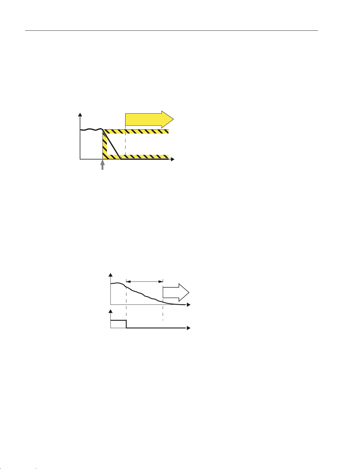
2.2.2 Safe Stop 1 (SS1)
Definition
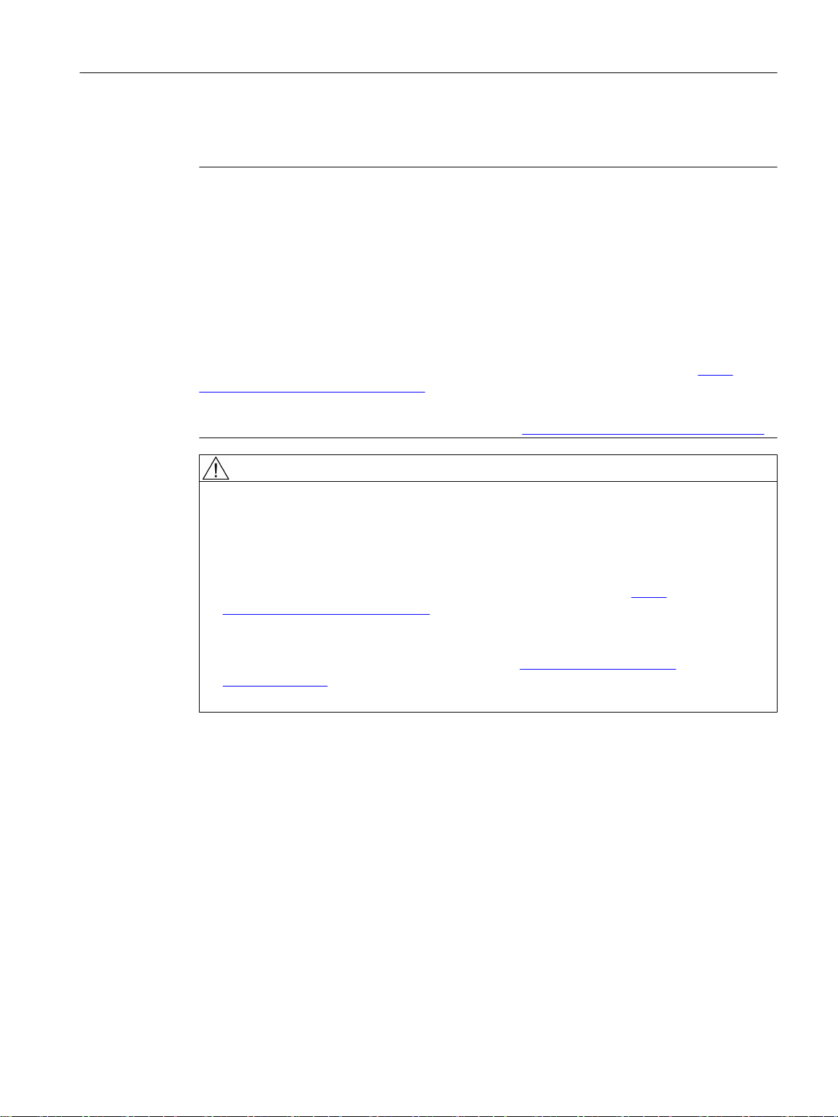
Definition according to EN 61800-5-2:
"The function SS1 brakes the motor and trips the function STO after a delay time."
Example of how the function can be used
● For an Emergency Stop, a drive must be braked as quickly as possible, and then
transitioned into STO.
How does SS1 function in detail?
The drive decelerates once "Safe Stop 1" has been selected, and goes into the "Safe Torque
Off" state once the delay time has expired.
Select SS1
As soon as the inverter detects the selection of SS1 via a terminal, the following happens:
● If, when selecting SS1 , the motor is already switched off, then until the SS1 delay time
expires, there is no response. STO becomes active after the time expires.
28 Function Manual, 10/2015, 6FC5397-3EP40-5BA3
● If the motor is switched on when SS1 is selected, the inverter brakes the motor with the
AUS3 ramp-down time. STO is automatically initiated after the time expires.
Safety Integrated
Page 29
2.2.3 Safe Brake Control (SBC)
6SHHG
6HOHFW672
STO
SBC
W
7KHPRWRUWRUTXHLVVZLWFKHGRII
6%&VDIHW\FRQWUROVDEUDNH
6SHHG
'HVHOHFW672
)',
6726%&
W
W
Definition according to EN 61800-5-2:
"The SBC function supplies a safe output signal to control a holding brake."
Figure 2-1 Safe Brake Control (SBC)
Example of how the function can be used
● Two-channel safe control of a holding brake
Overview of Safety Integrated functions
2.2 Safety Integrated Basic Functions
How does SBC function in detail?
The inverter detects the selection of STO using a fail-safe input.
The inverter then safely switches off the torque of the connected motor.
SBC is (if configured) initiated together with STO. The Motor Module / Safe Brake Relay / Safe
Brake Adapter then executes the action and safely controls the outputs for the brake.
Safety Integrated
Function Manual, 10/2015, 6FC5397-3EP40-5BA3 29
Page 30
STO
Y
W
Select SS1
Overview of Safety Integrated functions
2.3 Safety Integrated Extended Functions
2.3 Safety Integrated Extended Functions
Precondition
A license is required to use the Safety Integrated Extended Functions.
Software option
You require the following software option in order to use this function:
"drive based SI-axis/spindle additional 1 axis/spindle".
Enter the associated license key via the operating software SINUMERIK Operate.
References
"SINUMERIK 828D Commissioning CNC", Commissioning Manual, Chapter "Checking and
entering licenses"
2.3.1 Safe Torque Off (STO)
For the control options and the functionality for "Safe Torque Off" (STO), refer to chapter
"Description of Safety Integrated Basic Functions (Page 27)".
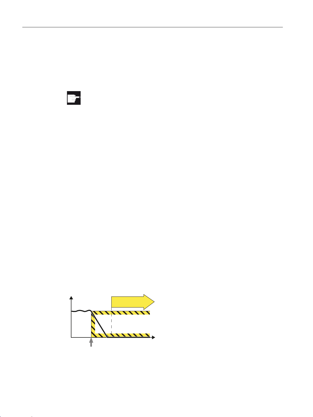
2.3.2 Safe Stop 1 (SS1)
Definition
Definition according to EN 61800-5-2:
"The function SS1 brakes the motor, monitors the magnitude of the motor deceleration within
specified limits, and after a delay time or if a speed threshold is exceeded, initiates the STO
function."
30 Function Manual, 10/2015, 6FC5397-3EP40-5BA3
Safety Integrated
Page 31

Example of how the function can be used
6SHHG
'HVHOHFW66
)',
0RQLWRULQJ
W
W
672
● For an Emergency Stop, a drive must be braked as quickly as possible, and then
transitioned into STO.
How does SS1 function in detail?
Using the SS1 function, the inverter brakes the motor and monitors the absolute speed. If the
motor speed is low enough or the delay time has expired, the inverter safely switches off the
motor torque using STO .
Overview of Safety Integrated functions
2.3 Safety Integrated Extended Functions
Select SS1
As soon as the inverter detects the selection of SS1 via a fail-safe input, the following happens:
● If the motor has already been switched off when selecting SS1 , then the inverter safely
switches off the motor torque (STO).
● If the motor is switched on when SS1 is selected, the inverter brakes the motor with the
AUS3 ramp-down time.
Monitoring modes
The "Acceleration monitoring" mode is available for Extended Functions (SAM).
Safety Integrated
Function Manual, 10/2015, 6FC5397-3EP40-5BA3 31
Page 32

6WDQGVWLOO
PRQLWRULQJ
6KXWGRZQ
YHORFLW\
W
6SHHG
'HVHOHFW66
)',
)'2
672DFWLYH
6$0
672
W
W
Overview of Safety Integrated functions
2.3 Safety Integrated Extended Functions
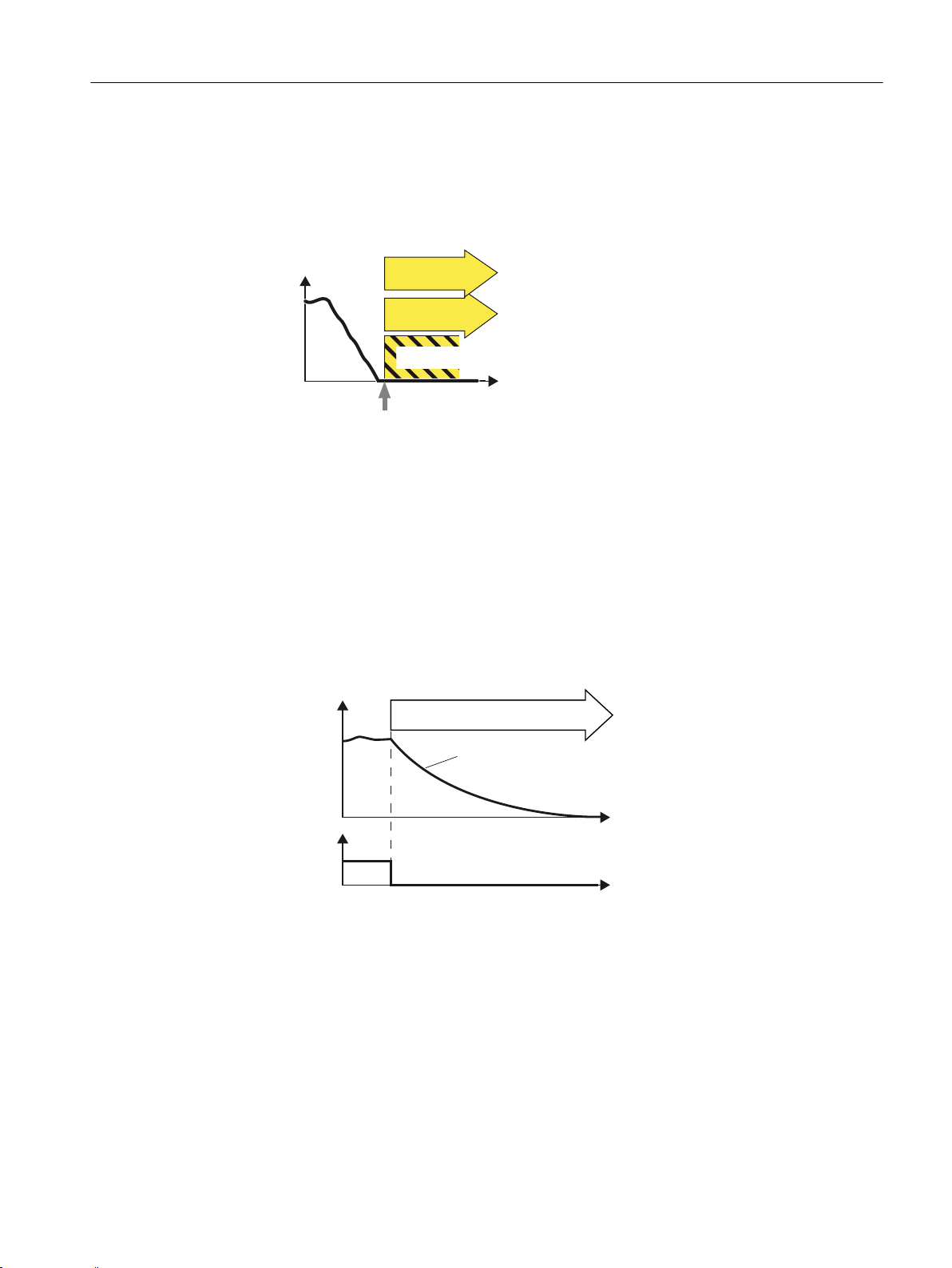
Acceleration monitoring
For Extended Functions, there is only the "Acceleration monitoring" mode:
● The inverter monitors the motor speed using the function SAM (Safe Acceleration
Monitor).
● The inverter prevents the motor from re-accelerating by continuously adjusting the
monitoring threshold to the decreasing speed.
● The inverter reduces the monitoring threshold until the "Shutdown speed" has been
reached.
● The inverter safely switches off the motor torque (STO) if one of the following conditions is
fulfilled:
– The speed has fallen below the shutdown speed SS1.
– The maximum time until the torque is switched off has expired.
Note
SS1 without OFF3
If you use "SS1 without OFF3", then acceleration monitoring SAM is not active.
2.3.3 Safe Brake Control (SBC)
For the control options and the functionality for "Safe Brake Control" (SBC), refer to chapter
"Description of Safety Integrated Basic Functions (Page 29)".
32 Function Manual, 10/2015, 6FC5397-3EP40-5BA3
Safety Integrated
Page 33

2.3.4 Safe Operating Stop (SOS)
SOS selection
SOS
[
W
Definition
Definition according to EN 61800-5-2:
"The function is used to safely monitor the standstill position of a drive."
Overview of Safety Integrated functions
2.3 Safety Integrated Extended Functions
Example of how the function can be used
● Dangerous areas of the machine can be entered without having to disconnect the power
to the drives.
● Vertical axes are held in position without a brake.
How does SOS function in detail?
This function serves for fail-safe monitoring of the standstill position of a drive. The protected
machine areas can be entered without having to shut down the machine as long as SOS is
active.
Drive stopping is monitored using an SOS tolerance window. When this function is activated,
the actual position is saved as a comparative position, until SOS is deselected again. Any
delay time is cleared after SOS is deselected and the drive can be immediately moved.
The drive is stopped with SS1 when the standstill tolerance window is violated.
Note
Contrary to SS1 and SS2, SOS does not automatically brake the drive:
The control still enters the setpoint.
This means that in the user program of the control system, the system must respond to the
"SOS selected" bit so that the control system brings the drive to a standstill within the delay
time.
Safety Integrated
Function Manual, 10/2015, 6FC5397-3EP40-5BA3 33
Page 34

$FWXDOSRVLWLRQ
'HOD\WLPH626
6HOHFW626
;DFW
6WDQGVWLOOWROHUDQFH
'LDJQRVWLFV
'HVHOHFW626
2SHUDWRUDFWLRQV
'HVHOHFW626
626DFWLYH
W
W
626
626
SOS
Y
W
Select SS2
Overview of Safety Integrated functions
2.3 Safety Integrated Extended Functions
2.3.5 Safe Stop 2 (SS2)
Definition
Figure 2-2 Standstill tolerance
Definition according to EN 61800-5-2:
"The function SS2 brakes the motor, monitors the magnitude of the motor deceleration, and
after a delay time, initiates the SOS function."
34 Function Manual, 10/2015, 6FC5397-3EP40-5BA3
Safety Integrated
Page 35

Example of how the function can be used
6SHHG
'HVHOHFW
0RQLWRULQJ
W
W
)',
626
● Controlled braking of a drive in SOS.
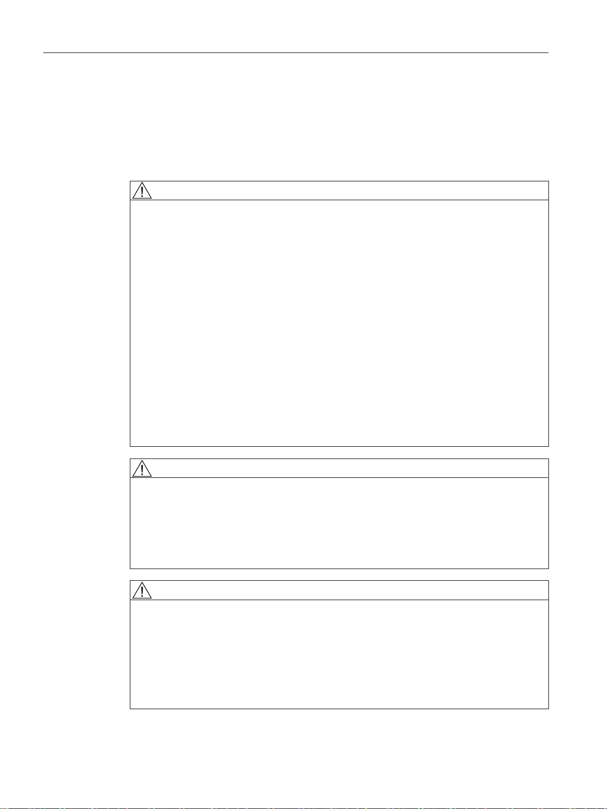
How does SS2 function in detail?
Overview
The safety function SS2 monitors the load speed and initiates the SOS function if the SS2
delay time has expired.
With SS2, braking is monitored along the OFF3 ramp. Incorrect acceleration is identified and
the drive then shuts down with STO.
Overview of Safety Integrated functions
2.3 Safety Integrated Extended Functions
If you are operating the motor with closed-loop torque control, the inverter switches to the
closed-loop speed control mode when SS2 is selected.
Detailed description
The SS2 safety function operates as follows:
● The machine control selects the SS2 safety function using a fail-safe input:
– If the motor is already at a standstill when selecting SS2, after a delay time, the inverter
activates the Safe Operating Stop function (SOS).
– If the motor is not at standstill when SS2 is selected, it is braked along the OFF3 ramp.
Braking is monitored using the Safe Acceleration Monitor (SAM) function. Incorrect
acceleration is therefore detected.
● After a delay time, the inverter activates the Safe Operating Stop function (SOS). This
function safety monitors the standstill of the drive.
Safety Integrated
Function Manual, 10/2015, 6FC5397-3EP40-5BA3 35
Page 36

$FWXDOYDOXH
'HOD\WLPH66
6HOHFW66
/RDGVSHHG
'LDJQRVWLFV
'HVHOHFW626
2SHUDWRUDFWLRQV
'HVHOHFW66
6$06%5DFWLYH
66DFWLYH
626DFWLYH
6$0
626
626
W
W
Overview of Safety Integrated functions
2.3 Safety Integrated Extended Functions
Braking response
Figure 2-3 Braking behavior and diagnostics of the safety function SS2 (Safe Stop 2)
2.3.6 Safely Limited Speed (SLS)
Definition
Definition according to EN 61800-5-2:
"The SLS function prevents the motor from exceeding the specified speed limit."
36 Function Manual, 10/2015, 6FC5397-3EP40-5BA3
Safety Integrated
Page 37

Select SLS
SLS
Y
W
Examples of how the function can be used
6SHHG
'HVHOHFW6/6
)',
6/6
6/6
W
W
● Traversing axes in the setting up mode with the protective doors open.
How does SLS function in detail?
1. The inverter detects the selection of SLS using a fail-safe input.
2. SLS allows a motor to reduce its possibly inadmissibly high speed within a defined time.
Overview of Safety Integrated functions
2.3 Safety Integrated Extended Functions
3. SLS monitors the absolute value of the actual velocity.
In addition, you can parameterize SLS so that SLS limits the velocity to values below the
monitoring threshold.
Note
As an alternative to control via terminals, there is also an option to parameterize the SLS
without selection function. In this case, the SLS function is permanently active after POWER
ON.
Select SLS with the motor switched on
Safety Integrated
Function Manual, 10/2015, 6FC5397-3EP40-5BA3 37
As soon as the inverter detects the selection of SLS via a fail-safe input, the following happens:
Page 38

Overview of Safety Integrated functions
2.3 Safety Integrated Extended Functions
If the setpoint velocity limit is interconnected to the ramp-function generator, then the inverter
limits the velocity to a value below the SLS monitoring threshold and brakes the motor with
the AUS3 ramp-down time.
Safety Integrated
38 Function Manual, 10/2015, 6FC5397-3EP40-5BA3
Page 39

'HOD\WLPHIRU6/6FKDQJHRYHU
/LPLWDWLRQ
6HWSRLQW
'HVHOHFW6/6
)',
6/6DFWLYH
)'2
9HORFLW\
W
W
W
6/6
9HORFLW\
/LPLWLQJ
6HWSRLQW
'HVHOHFW6/6
)',
6/6DFWLYH
)'2
'HOD\WLPH6/6
W
W
W
6/6
Overview of Safety Integrated functions
2.3 Safety Integrated Extended Functions
For SLS, as monitoring function only SAM (Safe Acceleration Monitor) is available.
● Without brake ramp monitoring:
The inverter monitors the load velocity after the "delay time for SLS changeover" has
expired.
Advantage: Commissioning is simplified, as instead of subfunction SAM of the alternative
brake ramp monitoring, you only have to set the delay time.
● Select SLS for low velocities
If the motor velocity when selecting SLS is less than the SLSlimit, then the drive responds
as follows:
The inverter monitors the velocity without any delay time.
● Deselect SLS
If the higher-level control deselects SLS , then the inverter deactivates limiting and
monitoring.
Safety Integrated
Function Manual, 10/2015, 6FC5397-3EP40-5BA3 39
Page 40

9HORFLW\
/LPLWOHYHO
/LPLWOHYHO
9HORFLW\
/LPLWOHYHO
/LPLWOHYHO
W
6/6
6/6
Overview of Safety Integrated functions
2.3 Safety Integrated Extended Functions
Switching over monitoring limits
When SLS is active, you can switch over between four different speed levels. An exception is
"SLS without selection": In this case, there is only one limit.
● Switching to a lower speed level
Without brake ramp monitoring:
The inverter monitors the velocity with the lower SLS level after the "delay time for SLS
changeover" has expired (this is the same delay time that applies after selecting the function
SLS).
● Switching to a higher speed level
If you switch over from a lower to a higher speed level, the inverter immediately monitors
the actual velocity against the higher velocity.
2.3.7 Safe Speed Monitor (SSM)
Definition
Definition according to EN 61800-5-2:
"The SSM function supplies a safe output signal to indicate whether the motor speed is below
a specified limit value."
40 Function Manual, 10/2015, 6FC5397-3EP40-5BA3
Safety Integrated
Page 41

Y
W
6SHHGEHORZ
WKHOLPLWYDOXH
W
660RXWSXWVLJQDO
Overview of Safety Integrated functions
2.3 Safety Integrated Extended Functions
Note
SSM is a pure signaling function.
Contrary to other Safety Integrated functions, a violation of the SSM limit does not result in a
drive-based stop response.
Example of how the function can be used
● A protective door may only be opened if all of the drives are at a complete standstill.
How does SSM function in detail?
Preconditions:
● The safety function SSM cannot be selected or deselected using external control signals.
● SSM is active, if you have set a monitoring speed > 0 for SSM .
Evaluating the speed
The inverter compares the load speed with the speed limit and signals if the limit value falls
below the higher-level control.
Parameterizable hysteresis
The parameterizable hysteresis ensures that the SSM output signal does not jump between
the values "0" and "1" in the limit range.
Safety Integrated
Function Manual, 10/2015, 6FC5397-3EP40-5BA3 41
Page 42

6SHHG
+\VWHUHVLV
+\VWHUHVLV
6SHHGEHORZWKHOLPLW
YDOXH
)'2
660
660
W
W
SDI
Y
W
Overview of Safety Integrated functions
2.3 Safety Integrated Extended Functions
Figure 2-4 Time response of the safety function SSM (Safe Speed Monitor)
2.3.8 Safe Direction (SDI)
Definition
Definition according to EN 61800-5-2:
"The SDI function prevents that the motor shaft rotates in the unintended direction."
Examples of how the function can be used
● Tools, which when machining may only rotate in one direction.
● Retracting from a safe software limit switch.
How does SDI function in detail?
42 Function Manual, 10/2015, 6FC5397-3EP40-5BA3
SDI monitors the actual direction of rotation.
Safety Integrated
Page 43

6SHHG
W
6',GHVHOHFW
)',
W
6',
9HU]¸JHUXQJV]HLW
6',
Overview of Safety Integrated functions
2.3 Safety Integrated Extended Functions
In addition, you can parameterize SDI so that SDI limits the speed to values in the permitted
direction.
Independently of one another, you can parameterize as to whether SDI limits the values in the
positive and/or negative direction.
Safety Integrated
Function Manual, 10/2015, 6FC5397-3EP40-5BA3 43
Page 44

6SHHG
6HWSRLQW
6',GHVHOHFW
)',
'HVHOHFW6',
)',
)'2
6',DFWLYH
)'2
6',DFWLYH
'HOD\
'HOD\
/LPLWHGWRVSHHGV!
/LPLWHGWRVSHHGV
W
6',
6',
W
W
W
W
Overview of Safety Integrated functions
2.3 Safety Integrated Extended Functions
Selecting and deselecting SDI
As soon as the inverter detects the selection of SDI via a fail-safe input, the following happens:
● You can also set a delay time, within which time you can ensure that the inverter moves in
the enabled (safe) direction.
● You can also set a tolerance, within which the inverter tolerates movement in the direction
that has not been enabled (safe).
● After the delay time has expired, the inverter monitors the direction of rotation of the motor.
2.3.9 Safely-Limited Position (SLP)
44 Function Manual, 10/2015, 6FC5397-3EP40-5BA3
Figure 2-5 Time response of the safety function SDI (Safe Direction)
Note
As an alternative to control via terminals, there is also an option to parameterize the SDI
without selection function. In this case, the SDI function is permanently active after POWER
ON.
Definition according to EN 61800-5-2:
"The SLP function prevents the motor shaft from exceeding the specified position limit(s)."
Safety Integrated
Page 45

6HOHFWLRQ6ZLWFKRYHU
6BR
6BX
Y
W
6BR
6BX
6/3
Function Safely-Limited Position (safely limited position, SLP) is used to safely monitor the
limits of two traversing or positioning ranges that are switched between using a safe signal.
Examples of how the function can be used
● Limiting the traversing range of an axis without using a hardware limit switch.
Features
● Selection via terminals
● 2 position ranges, each defined by a limit switch pair
Overview of Safety Integrated functions
2.3 Safety Integrated Extended Functions
● Safe switchover between the two position ranges
● Adjustable stop response
● To move the motor out of the unauthorized range, you must execute a special sequence.
Preconditions
● The function is only available with a suitable encoder.
● The drive must be safely referenced (using "Reference point approach" and user
agreement).
2.3.10 Safe Brake Test (SBT)
The "Safe Brake Test" function (SBT) checks the required holding torque of a brake
(operational or holding brake). The drive purposely generates a force/torque against the
applied brake. If the brake is operating correctly, the axis motion remains within a
parameterized tolerance. If, however, a larger axis motion is detected, it must be assumed
that the braking force/torque has deteriorated and maintenance is required.
The "Safe Brake Test" function allows a safe test of up to two brakes:
● 1 motor holding brake and 1 external brake
Safety Integrated
Function Manual, 10/2015, 6FC5397-3EP40-5BA3 45
● 2 external brakes
● 1 motor holding brake
● 1 external brake
Page 46

Overview of Safety Integrated functions
2.3 Safety Integrated Extended Functions
Safety Integrated
46 Function Manual, 10/2015, 6FC5397-3EP40-5BA3
Page 47

Commissioning - drive-based
3.1 Introduction
Commissioning mode
As long as the displayed drive is not in the commissioning mode, most of the entry fields are
deactivated. This mode is subsequently called the view mode.
The drive must be in the commissioning mode in order to commission the safety functions.
This has the following special feature: The safety-relevant parameters are monitored by the
real-time software using an actual checksum. This actual checksum is adapted as soon as a
safety-relevant parameter is changed. If the commissioning mode is to be exited, then this
actual checksum is compared with a reference checksum. The commissioning mode cannot
be exited as long as these checksums differ. The reference checksum must be aligned with
the actual checksum. The reference checksum is written using the "Confirm SI data" function;
when doing this, the actual checksum is copied over into the reference checksum.
The general safety parameterization is carried out in the safety settings. Here, the safety
functions applicable for the actual drive are also set.
All additional parameter assignments for the selected drive must then be subsequently made
in the individual safety function of the drive.
3
The commissioning mode must be activated for the safety settings as well as for the safety
functions of a drive if changes to the parameter assignment are necessary. Only a few basis
settings can be changed without the commissioning mode being activated.
Two-channel parameterization
Safety functions must be parameterized through two channel; this means that there is one
parameter each for the 1st and 2nd channels. These two parameters must be identically
parameterized. You can find the corresponding parameters in the parameter description of the
SINAMICS S120/S150 List Manual.
The parameters of the first monitoring channel are set in the windows; the parameters of the
second monitoring channel are then copied over using the "Copy SI data" from the first into
the second monitoring channel. The checksum must then be realigned, i.e. "Confirm SI data"
must be carried out.
Safety Integrated
Function Manual, 10/2015, 6FC5397-3EP40-5BA3 47
Page 48

Commissioning - drive-based
3.1 Introduction
Hardware replacement
If a hardware component is replaced after completing the safety commissioning then the
hardware replacement must be confirmed. Confirmation is required when replacing the
following hardware components:
● Control Unit
● Motor Module
● Sensor Module
Parameter lists
As an alternative to changing parameters using the dialog window, you can also check or
correct parameters using the parameter lists (Page 56). When doing this, you can
simultaneously make the settings for both monitoring channels.
Safety Integrated
48 Function Manual, 10/2015, 6FC5397-3EP40-5BA3
Page 49

3.2 Activating the commissioning mode
You can call the commissioning mode both for the safety settings as well as for the individual
safety functions.
Procedure
1. Select the "Start-up" operating area.
2. Press the menu forward key and the "Safety" softkey.
3. Press the "Settings" softkey, and then select a setting area (e.g. options)
using the appropriate softkeys.
Activating the commissioning mode for a drive
Activating the commissioning mode for all drives
- OR Press the "Functions" softkey, and then select a safety function (e.g.
SBC) using the appropriate softkeys.
4. Select the required drive using softkey "Drive+", or "Drive-".
- OR -
Press the "Select drive" softkey.
This softkey is only visible if there are several drives.
A selection of all of the axes and drives that exist in the drive system is
displayed.
Select the required drive.
Press the "OK" softkey to complete the drive selection.
5. Press the ">>" softkey.
Then press the "Act./deact. drv. comm." softkey
A prompt to activate the commissioning mode is displayed.
6. Press the "OK" softkey to activate the commissioning mode for the actual
drive.
- OR -
Press the "Cancel" softkey.
In this particular case, activating the commissioning mode is canceled.
5. Press the "Change" softkey.
Commissioning - drive-based
3.2 Activating the commissioning mode
Safety Integrated
Function Manual, 10/2015, 6FC5397-3EP40-5BA3 49
Page 50

Commissioning - drive-based
3.2 Activating the commissioning mode
6. Press the "Activate for all drives" softkey to activate the commissioning
mode for all drives.
This softkey is only visible if there are several drives.
- OR Press the "OK" softkey to activate the commissioning mode for the actual
drive.
The prompt is closed. The entry fields in the window are active.
- OR Press the "Cancel" softkey.
In this particular case, activating the commissioning mode is canceled.
Safety Integrated
50 Function Manual, 10/2015, 6FC5397-3EP40-5BA3
Page 51

3.3 Canceling the commissioning mode
The commissioning mode can be immediately exited if no safety parameters were changed.
If safety parameters were changed, before exiting the commissioning mode, it still has to be
defined what should happen with the modified safety parameters.
Procedure
1. You wish to cancel the commissioning mode.
Press the "Cancel" softkey.
Based on the checksums, the program checks as to whether SI parame‐
ters were changed.
If this is not the case, then the commissioning mode is exited at this point.
- OR If the program identifies that SI parameters were changed, then a prompt
is displayed as to what should happen with the modified data.
Objective: Confirm the changed data
2a. Press the "OK" softkey to confirm the data of the actual drive and to exit
the commissioning mode. The actual checksum of the actual drive is
copied over to the reference checksum.
- OR -
Press the "Confirm all drives" softkey to confirm the data of all drives and
to exit the commissioning mode. The actual checksum of all drives is
copied over to the reference checksum.
This softkey is only visible if there are several drives in your drive system.
2b. Objective: Undo changes
Press the "Reset (po)" softkey to undo all changes to the data. A POWER
ON reset is then carried out. You have the option to save the data if you
have changed it.
2c. Objective: Remain in the commissioning mode
Press the "Cancel" softkey if you do not wish to exit the commissioning
mode.
The prompt is closed. The commissioning mode remains active.
Commissioning - drive-based
3.3 Canceling the commissioning mode
See also
Exit the commissioning mode (Page 52)
Safety Integrated
Function Manual, 10/2015, 6FC5397-3EP40-5BA3 51
Page 52

Commissioning - drive-based
3.4 Exit the commissioning mode
3.4 Exit the commissioning mode
The commissioning mode can be immediately exited if no safety parameters were changed.
If safety parameters were changed, before exiting the commissioning mode, it still has to be
defined what should happen with the modified safety parameters.
Procedure
1. You wish to exit the commissioning mode.
Press the "OK" softkey.
Based on the checksums, the program checks as to whether SI parame‐
ters were changed.
If this is not the case, then the commissioning mode is exited at this point.
- OR A prompt appears if the program identifies that SI parameters have been
changed.
Objective: Only confirm data
2a. Press the "Confirm SI data" softkey.
As a consequence, the SI data of the actual drive are confirmed, and the
commissioning mode is exited.
- OR -
Press the "Confirm all drives" softkey.
As a consequence, the SI data of all drives is confirmed and the commis‐
sioning mode is then exited.
This softkey is only visible if there are several drives.
- OR -
Press the "Reset (po)" softkey.
This means that all changes to the SI data are undone. The NCK and the
complete drive system is then restarted.
Alternatively: Objective: Confirm the data and copy from the 1st into the 2nd safety
monitoring channel.
2b. Press the "OK" softkey.
The modified SI data of the current drive are copied to the 2nd safety
monitoring channel.
- OR -
Safety Integrated
52 Function Manual, 10/2015, 6FC5397-3EP40-5BA3
Page 53

Commissioning - drive-based
3.4 Exit the commissioning mode
Press the "Copy all drives" softkey.
In the commissioning mode, modified SI data of all drives is copied to the
2nd safety monitoring channel.
This softkey is only visible if there are several drives.
For both copy options, a prompt is then issued for subsequent actions,
which are necessary to exit the commissioning mode.
Press the "OK" softkey.
The settings of the SI data are confirmed, and the commissioning mode
is exited.
- OR -
Press the "Confirm all drives" softkey.
As a consequence, the SI data of all drives is confirmed and the commis‐
sioning mode is then exited.
This softkey is only visible if there are several drives.
- OR -
Press the "Reset (po)" softkey.
This means that all changes to the SI data are undone. The NCK and the
complete drive system is then restarted.
2c Objective: Remain in the commissioning mode
Press the "Cancel" softkey in order to close the window that has just been
opened without any interaction. The previous window is displayed again.
Safety Integrated
Function Manual, 10/2015, 6FC5397-3EP40-5BA3 53
Page 54

Commissioning - drive-based
3.5 Copying or confirming SI data
3.5 Copying or confirming SI data
As soon as the commissioning mode has been activated for a drive, the appropriate parameters
can be changed. The parameters are acquired for the first monitoring channel. Using the "Copy
SI data" function, the settings entered when commissioning are copied from the first into the
second monitoring channel. When exiting the commissioning mode normally, this function is
essentially automatically executed. However, it can also be manually initiated.
Copy SI data
1. The commissioning mode is active. You wish to copy the SI data that has
been acquired from the first into the second monitoring channel.
Press the ">>" softkey to display the softkeys of the second vertical soft‐
key bar.
2. Press the "Copy SI data" softkey.
A prompt "Copy SI data" is then displayed.
Here, you can define whether the SI data should be only copied for the
actual drive - or for all of the available drives.
3. Press the "OK" softkey to activate the SI data for the actual drive.
- OR -
Press the "Copy all drives" softkey to copy the SI data of all the available
drives.
The SI data are copied from the first into the second monitoring channel.
A prompt is then displayed as to whether you wish to exit the commis‐
sioning mode. If you wish to remain in the commissioning mode, you can
close the prompt using the "Cancel" softkey.
You must confirm the SI data if you wish to exit the commissioning mode
here.
4. Press the "OK" softkey to confirm the SI data for the actual drive.
- OR -
Press the "Confirm all drives" softkey to confirm the SI data of all the
available drives.
The commissioning mode is exited.
Alternatively:
Press the "Cancel" softkey.
Copying SI data is canceled.
Safety Integrated
54 Function Manual, 10/2015, 6FC5397-3EP40-5BA3
Page 55

Confirm SI data
Commissioning - drive-based
3.5 Copying or confirming SI data
1. The commissioning mode is active. You wish to confirm the SI data ac‐
quired and exit the commissioning mode.
Press the ">>" softkey to display the softkeys of the second vertical soft‐
key bar.
2. Press the "Confirm SI data" softkey.
A prompt "Confirm SI data" is then displayed.
Here, you can define whether the SI data should be only confirmed for
the actual drive - or for all of the available drives. With the confirmation,
the commissioning mode is exited.
3. Press the "OK" softkey to activate the SI data for the actual drive.
- OR -
Press the "Confirm all drives" softkey to confirm the SI data of all the
available drives.
The commissioning mode is exited.
Alternatively:
Press the "Cancel" softkey.
Confirming SI data is canceled. The commissioning mode remains active.
Safety Integrated
Function Manual, 10/2015, 6FC5397-3EP40-5BA3 55
Page 56

Commissioning - drive-based
3.6 Working with parameter lists
3.6 Working with parameter lists
As alternative to the dialog windows, you can also configure the basic safety settings and
functions directly via a parameter list. The parameter list can be called from the dialog window
of the particular safety basic setting or safety function.
Figure 3-1 Example of a parameter list
A minimum of 2 sublists are displayed in the list window:
● Upper list = data from the 1st monitoring channel
● Lower list = data from the 2nd monitoring channel
If parameters or drive machine data are not assigned to the 1st or 2nd monitoring channel,
they are displayed in a 3rd list below the list for the two monitoring channels.
The following data are displayed in the individual columns of each list:
● Parameter No.
● Parameter name
● Input field (white)
For r parameters, only values are displayed (= display field).
● Units
Safety Integrated
56 Function Manual, 10/2015, 6FC5397-3EP40-5BA3
Page 57

3.7 Safety overview
3.7.1 Calling the overview and detailed views
Procedure
1. Select the "Start-up" operating area.
2. Press the menu forward key and the "Safety" softkey.
3. Press the "Overview" softkey if the "Overview" setting area is not active.
Overview - calling the details
Press the "Details" softkey.
Commissioning - drive-based
3.7 Safety overview
Overview - calling the checksums
Press the "Checksums" softkey.
...
To exit the detailed view or the view of the checksums: press the "<<
Back" softkey.
The "Overview" window is displayed again.
Safety Integrated
Function Manual, 10/2015, 6FC5397-3EP40-5BA3 57
Page 58

Commissioning - drive-based
3.7 Safety overview
3.7.2 Safety Integrated overview
The most important information about the active safety functions is displayed in the "Overview"
window:
Figure 3-2 Overview
● Axis/drive
All NC axes and drives in the system are displayed in this column.
● Extended functions
This column displays whether and if yes, which extended functions are used for this axis
or this drive.
● Basic functions
This column displays as to whether a basic function is used for this axis or for this drive
and its associated control.
● Assignment
NC axis or internal Control Unit of the drive – or a drive object exists on the Control Unit,
to which an NC axis is assigned.
● SI start-up/commissioning mode
Indicates whether the commissioning mode is active for the drive.
● Status symbols
The parameters are evaluated through two channels. The status symbols indicate as to
whether the parameters are identical in both channels.
– Green: Parameterization identical in the 1st and 2nd monitoring channels
– Red: Parameterization different in the 1st and 2nd monitoring channels
Safety Integrated
58 Function Manual, 10/2015, 6FC5397-3EP40-5BA3
Page 59

Other options
You can supplement or switch over the display in the "Overview" window:
● Using the "Safe drives" softkey, you can toggle between the displays of "All drives" and
"Safe drives".
● Using the "Confirm SI HW" softkey, you can confirm that hardware components have been
replaced after safety commissioning has been completed.
● You can change to the detailed view using the "Details (Page 59)" softkey.
● Using the "Checksums (Page 60)" softkey, you can change to the dialog, which shows you
the safety checksums.
3.7.3 Safety Integrated overview - details
The most important detailed information about the active safety functions is displayed in the
"Overview - Details" window:
Commissioning - drive-based
3.7 Safety overview
Figure 3-3 Overview details
● Extended functions:
For extended functions, the settings from parameter p9501 are evaluated and displayed
for enabled functions.
● Basic functions:
For the basic functions, the settings from parameters p9601, p9602, p9652 are evaluated
and displayed if the function has been released.
This part of the window is not displayed if no basic functions were set up.
Safety Integrated
Function Manual, 10/2015, 6FC5397-3EP40-5BA3 59
Page 60

Commissioning - drive-based
3.7 Safety overview
● Status symbols:
The parameters are evaluated through two channels. The status symbols indicate as to
whether the parameters are identical in both channels.
– Green: Parameterization identical in the 1st and 2nd monitoring channels
– Red: Parameterization different in the 1st and 2nd monitoring channels
● Control
The control of the particular safety function is displayed in the right-hand column. The
control is determined from parameter p9601.
3.7.4 Safety Integrated overview - checksums
In the "Overview-checksums" window, all of the safety reference and actual checksums are
displayed for the axes and drives.
Figure 3-4 Overview-checksums
Status symbols are used to flag differences between reference and actual checksums:
● Green: Reference and actual checksums are identical
● Red: Reference and actual checksums are different
Safety Integrated
60 Function Manual, 10/2015, 6FC5397-3EP40-5BA3
Page 61

Commissioning - drive-based
3.7 Safety overview
The checksums are read from the SI parameters. An overview is provided below:
Monitoring channel 1 (Control Unit) Monitoring channel 2 (Motor Module)
Actual checksum Reference checksum Actual checksum Reference checksum
Extended functions
Motion monitoring r9728[0] p9729[0] r9398[0] p9399[0]
Actual values r9728[1] p9729[1] ‑ ‑
Hardware r9728[2] p9729[2] r9398[1] p9399[1]
Basic function r9798 p9799 r9898 p9899
Safety Integrated
Function Manual, 10/2015, 6FC5397-3EP40-5BA3 61
Page 62

Commissioning - drive-based
3.8 Making the basic safety settings
3.8 Making the basic safety settings
3.8.1 Calling the basic setting dialog
Procedure
1. Select the "Start-up" operating area.
2. Press the menu forward key and the "Safety" softkey.
3. Press the "Settings" softkey.
Safety Integrated
62 Function Manual, 10/2015, 6FC5397-3EP40-5BA3
Page 63

Commissioning - drive-based
3.8 Making the basic safety settings
4. For each drive, the required basic setting ranges can be called using
softkeys with the same name.
Press the appropriate softkey:
● "Options"
● "Configuration"
● "Encoder parameterization"
● "Telegram configuration"
5. Select the required drive using softkey "Drive+", or "Drive-".
- OR -
Press the "Select drive" softkey.
This softkey is only visible if there are several drives.
A selection of all of the axes and drives that exist in the drive system is
displayed.
Select the required drive.
Press the "OK" softkey to complete the drive selection.
Safety Integrated
Function Manual, 10/2015, 6FC5397-3EP40-5BA3 63
Page 64

Commissioning - drive-based
3.8 Making the basic safety settings
3.8.2 Options
In the "Settings - Options" window, you can select and enable the safety functions for the
selected drive.
Figure 3-5 Options
Safety Integrated
64 Function Manual, 10/2015, 6FC5397-3EP40-5BA3
Page 65

Commissioning - drive-based
3.8 Making the basic safety settings
The following settings are possible:
● Selecting a safety function:
– The selected safety function defines the remaining setting options for the safety
functions.
– The selection of "Function specification" is orientated according to the activated safety
function. For the 828D, the function specification is permanently set for the extended
functions.
The following safety functions can be selected:
– No safety function
– Basic functions via onboard terminals
– Extended Functions via the TM54F
– Extended functions via the TM54F and basic functions via onboard terminals.
● Evaluation factors to define the setpoint limits
This option is only activated when an Extended safety function has been set. This option
can also be defined if the commissioning mode is not active.
You can directly enter the evaluation factors in the input fields as percentage. Alternatively,
you can go to a dialog by pressing the "Recommended values" softkey. Here, the axis
machine data is always preassigned 80 % – and the drive parameters 100 %. You can
accept these recommended values by pressing the "Yes" softkey. You can exit the dialog
with "No" without accepting the values.
● Reaction of the stop response
The reaction of the stop response can be defined here for NC axes.
Status display
The status of the safety monitoring functions is shown in the right-hand section of the window.
The contents of this status display depend on whether Basic Safety functions or Extended
functions have been selected.
Recommended values
As an alternative to the manual input in the displayed input fields, you can go to a dialog by
pressing the "Recommended values" softkey. In this dialog, you can accept the recommended
values from the axis machine data. The following recommended values, which can be edited,
are suggested:
● Axis machine data: 80 %
● Drive (p9533): 100 %
You can accept these recommended values by pressing the "Yes" softkey. The data are then
copied from the encoder parameterization into the 1st and 2nd monitoring channels. You can
exit the dialog with "No" without accepting the values.
Parameter list
When required, each setting in this dialog window can also be made via a parameter list. You
can access the parameter list (Page 56) using the ">>" softkey followed by the "Parameter list"
softkey.
Safety Integrated
Function Manual, 10/2015, 6FC5397-3EP40-5BA3 65
Page 66

Commissioning - drive-based
3.8 Making the basic safety settings
3.8.3 Configuration
Precondition
The "Settings - Configuration" window is only available if beforehand an extended safety
function was selected for the actual drive (see Options (Page 64)).
Settings
You can make the following settings in the "Settings - Configuration" window:
Figure 3-6 Configuration
● Monitoring clock cycle (p9500)
Setting the monitoring clock cycle for safety motion monitoring functions in ms.
● Actual value sensing cycle (p9511)
Setting the clock cycle in ms of the actual value sensing for the safety motion monitoring
functions in ms.
● Extended alarm acknowledgment (p9507.0)
When this option is activated, a safe acknowledgment can be performed by selecting/
deselecting STO or SS1.
This setting is not displayed for integrated drives.
● Shutoff valve available (p0218.0)
Setting the configuration for the safety circuit of the cylinder; only for HLA.
● Select test stop (p9705)
Sets the signal source for the test stop of the safe motion monitoring functions.
Safety Integrated
66 Function Manual, 10/2015, 6FC5397-3EP40-5BA3
Page 67

Commissioning - drive-based
3.8 Making the basic safety settings
● Test time, pulse cancellation (p9557)
Sets the time in ms when, after the test stop has been initiated, STO must become active.
● Forced checking procedure timer (p9559)
Sets the time interval in hours for carrying out dynamization and testing the safety motion
monitoring functions integrated in the drive.
● Forced checking procedure required (r9723.0)
One or more interconnections are possible, but not mandatory. When selected, the BICO
editor is started to select the signal target.
Only "Safe positioning accuracy (r9731)", "Safe maximum velocity (r9730)" and the "Remaining
time until the test stop" (p9765) are displayed.
Parameter list
When required, each setting in this dialog window can also be made via a parameter list. You
can access the parameter list (Page 56) using the ">>" softkey followed by the "Parameter list"
softkey.
3.8.4 Encoder parameterization
Precondition
The "Settings - Encoder parameterization" window is only available if beforehand an extended
safety function was selected for the actual drive (see Options (Page 64)). The commissioning
mode (Page 49) must be activated to change the configuration.
Safety Integrated
Function Manual, 10/2015, 6FC5397-3EP40-5BA3 67
Page 68

Commissioning - drive-based
3.8 Making the basic safety settings
Setting range "Encoder selection, encoder data and actual value synchronization"
The following settings are possible in the window "Settings - encoder parameterization":
Figure 3-7 Encoder parameterization: Encoder selection, encoder data, actual value synchronization
● Axis type (p9502)
Either a linear axis or a rotary axis/spindle can be defined here as axis type.
● Encoder selection, 2nd monitoring channel (p9526)
When more than one encoder is configured for the drive, an encoder for the 2nd monitoring
channel can be defined here.
● Encoder 1st monitoring channel
– Encoder type (p9516.0), display only
Sets the configuration for motor encoder and position actual value. Indicates whether a
rotary or a linear encoder is used.
– Invert position actual value (p9516.1)
Set sign change for the encoder type.
– Encoder pulse number (p9518)
Sets the number of encoder pulses per revolution for rotary encoders.
– Fine resolution X_IST1 (p9519), display only
Sets the fine resolution for G1_XIST1 in bits.
– Spindle pitch (p9520)
Sets the ratio between the encoder and load in mm/revolutions for a linear axis with
rotary encoder.
Safety Integrated
68 Function Manual, 10/2015, 6FC5397-3EP40-5BA3
Page 69

Commissioning - drive-based
3.8 Making the basic safety settings
● Encoder 2nd monitoring channel
– Encoder type (p9316.0)
Sets the configuration for encoder and position actual value. The encoder, which is used
for safe motion monitoring on the Motor Module must be parameterized in this parameter.
– Invert position actual value (p9316.1)
Set sign change for the encoder type.
– Encoder pulse number (p9318)
Sets the number of encoder pulses per revolution for rotary encoders.
– Fine resolution X_IST2 (p9319)
Sets the fine resolution for G1_XIST1 in bits.
– Spindle pitch (p9320)
Sets the ratio between the encoder and load in mm/revolutions for a linear axis with
rotary encoder.
● Actual value synchronization
The actual value synchronization can only be parameterized for systems equipped with 2
encoders. When SLP is enabled, actual value synchronization is not permitted.
– Enable (p9501.3)
Sets the enable signals for the safety-related motion monitoring functions when SLP
(SE) is enabled.
– Actual value tolerance (p9542)
Sets the tolerance in mm for linear axes or degrees for rotary axes for the crosswise
comparison of the actual position between the two monitoring channels.
The add. actual value tolerance (r9708[5]) and the maximum actual value tolerance
(r9708[3]) are only displayed. They indicate the load-side additional or maximum actual
value difference Control Unit – second monitoring channel.
Recommended values
As an alternative to the manual input in the displayed input fields, you can go to a dialog by
pressing the "Recommended values" softkey. In this dialog, you can accept the recommended
values from the encoder data of the axis machine data. The data are then copied from the
encoder parameterization into the 1st and 2nd monitoring channels. You can accept these
recommended values by pressing the "Yes" softkey. You can exit the dialog with "No" without
accepting the values.
Note
It is not possible to use the "Recommended values" softkey for drives without NC axis
assignment. Instead of this, the "Copy encoder data" softkey is visible. In this case, standard
encoder parameters can be copied to the safety encoder parameters. You can accept these
recommended values by pressing the "Yes" softkey. You can exit the dialog with "No" without
accepting the values.
Parameter list
When required, each setting in this dialog window can also be made via a parameter list. You
can access the parameter list (Page 56) using the ">>" softkey followed by the "Parameter list"
softkey.
Safety Integrated
Function Manual, 10/2015, 6FC5397-3EP40-5BA3 69
Page 70

Commissioning - drive-based
3.8 Making the basic safety settings
3.8.5 Telegram configuration
Precondition
The "Settings - telegram configuration" window is only available if the commissioning mode
(Page 49) has been activated for the drive.
Settings
You can make the following settings in the "Settings - Telegram configuration" window:
Figure 3-8 Telegram configuration
● Enable SIC/SCC
Activates the enable and setting of the SIC/SCC module number.
● SIC/SCC telegram
Sets the telegram configuration for 828D. The "[701] supplementary telegram 701,
PZD-2/5" telegram must be selected here.
Parameter list
When required, each setting in this dialog window can also be made via a parameter list. You
can access the parameter list (Page 56) using the ">>" softkey followed by the "Parameter list"
softkey.
Safety Integrated
70 Function Manual, 10/2015, 6FC5397-3EP40-5BA3
Page 71

3.9 Safety Integrated functions
3.9.1 Calling function dialogs
Procedure
1. Select the "Start-up" operating area.
2. Press the menu forward key and the "Safety" softkey.
3. Press the "Functions" softkey.
Commissioning - drive-based
3.9 Safety Integrated functions
4. Press the softkey of the required safety function:
● STO/SS1 Basic
● SBC
● STO Extended
● SS2/SOS
● SLS
● SSM
● SAM
● SDI
● SLP
● SBT
5. Select the required drive using softkey "Drive+", or "Drive-".
- OR -
Press the "Select drive" softkey.
This softkey is only visible if there are several drives.
6. Activate the commissioning mode if this has not already been done.
A selection of all of the axes and drives that exist in the drive system is
displayed.
Select the required drive.
Press the "OK" softkey to complete the drive selection.
Safety Integrated
Function Manual, 10/2015, 6FC5397-3EP40-5BA3 71
Page 72

Commissioning - drive-based
3.9 Safety Integrated functions
3.9.2 Safe Torque Off (STO)/Safe Stop 1 (SS1) - basis function
In conjunction with a machine function or in the event of a fault, the "Safe Torque Off" (STO)
function is used to safely disconnect the torque-generating energy supply to the motor.
Precondition
The commissioning mode (Page 49) must be activated so that the parameters of this safety
function can be changed. A basic function must be set in the options (Page 64).
Settings
You can make the following settings in this window:
Figure 3-9 Safe Torque Off - Safe Stop 1 - STO/SS1 Basic
● Control Unit terminal (p9620[0])
Sets the signal source for the STO, SBC and SS1 functions of the Control Unit.
This is only relevant if a basic function via terminal is set in the options (Page 64). Otherwise,
the input field is deactivated.
● SS1 delay time (p9652)
Sets the delay time of the pulse cancellation in seconds for the function "Safe Stop 1" (SS1)
on the Control Unit to brake along the OFF3 down ramp (p1135).
● Braking response for SS1 (p9653)
Select a predefined braking response below the input field "SS1 delay time". Parameter
p9653 is preassigned depending on the selected braking response.
Safety Integrated
72 Function Manual, 10/2015, 6FC5397-3EP40-5BA3
Page 73

Commissioning - drive-based
3.9 Safety Integrated functions
● F-DI input filter (p9651)
Setting the debounce time in ms for the fail-safe digital inputs to control STO/SBC/SS1.
● Simultaneity monitoring (p9650)
Sets the discrepancy time in ms for the switchover of the safety-relevant inputs (SGE) on
the Control Unit.
● Delay time STOP F -> STOP A (p9658)
Sets the transition time from STOP F to STOP A in ms on the Control Unit.
● Forced checking procedure of the switch-off signal paths (p9659)
Sets the time interval in hours for carrying out the forced checking procedure and testing
the switch-off signal paths.
● Switch-off signal paths must be tested (r9773.31)
To evaluate whether the switch-off signal paths must be tested, the status of r9773.31
“Switch-off signal path must be tested" can be interconnected with a parameter via the
BICO editor.
For the following parameters, the status symbols indicate the actual state (blue = active; gray
= inactive):
● STO selected (r9772.0)
"STO selected in the drive" setting
● No text (brake reaction) (r9773.2)
Setting "SS1 Delay time active in the drive"
● Pulse inhibit channel 1 active (r9772.1)
Setting "STO or safe pulse cancellation active on the CU"
● Pulse inhibit channel 2 active (r9872.1)
Setting "STO on Motor Module active"
● STO active (r9773.1)
Setting "STO active in the drive"
● Switch-off signal paths must be tested (r9773.31)
Setting “Switch-off signal paths must be tested"
Parameter list
When required, alternatively you can use a parameter list for each setting in this window. You
can access the parameter list (Page 56) using the ">>" softkey followed by the "Parameter list"
softkey.
3.9.3 Safe Torque Off (STO) - extended function
In conjunction with a machine function or in the event of a fault, the "Safe Torque Off" (STO)
function is used to safely disconnect the torque-generating energy supply to the motor.
A restart is prevented by the two-channel pulse suppression. The switching on inhibited
prevents an automatic restart after deselection of STO.
The two-channel pulse cancellation function integrated in the Motor Modules / Power Modules
is a basis for this function.
Safety Integrated
Function Manual, 10/2015, 6FC5397-3EP40-5BA3 73
Page 74

Commissioning - drive-based
3.9 Safety Integrated functions
Precondition
The commissioning mode (Page 49) must be activated so that the parameters of this safety
function can be changed. An extended function must be set in the options (Page 64).
Settings
You can make the following settings in this window:
Figure 3-10 Safe Torque Off
● Forced checking procedure of the switch-off signal paths (p9659)
Sets the time interval in hours for carrying out the forced checking procedure and testing
the switch-off signal paths.
● Switch-off signal paths must be tested (r9773.31)
To evaluate whether the switch-off signal paths must be tested, the status of r9773.31
“Switch-off signal path must be tested" can be interconnected with a parameter via the
BICO editor.
For the following parameters, the status symbols indicate the actual state (blue = active; gray
= inactive):
● STO selected (r9773.0)
"STO selected in the drive" setting
● Pulse inhibit active (r9772.1)
Setting "STO or safe pulse cancellation active on the CU"
Safety Integrated
74 Function Manual, 10/2015, 6FC5397-3EP40-5BA3
Page 75

● STO active (r9773.1)
Setting "STO active in the drive"
● Forced checking procedure required (r9773.31)
Setting “Switch-off signal paths must be tested"
Parameter list
When required, alternatively you can use a parameter list for each setting in this window. You
can access the parameter list (Page 56) using the ">>" softkey followed by the "Parameter list"
softkey.
3.9.4 Safe Brake Control (SBC)
The "Safe Brake Control" function (SBC) is used to safely control holding brakes that function
according to the closed-circuit principle (e.g. motor holding brake).
Brake activation via the brake connection on the Motor Module/Safe Brake Adapter (SBA)
involves a safe, two-channel method.
Commissioning - drive-based
3.9 Safety Integrated functions
Precondition
The commissioning mode (Page 49) must be activated so that the parameters of this safety
function can be changed.
Safety Integrated
Function Manual, 10/2015, 6FC5397-3EP40-5BA3 75
Page 76

Commissioning - drive-based
3.9 Safety Integrated functions
Settings
You can only make one setting in this window:
Figure 3-11 Safe brake control - SBC
● Safe brake control (p9602)
The safe brake control can be enabled or inhibited using this selection list. This selection
list is deactivated if a motor holding brake is not included in the configuration (p1215).
For the following parameters, the status symbols indicate the actual state (blue = active; gray
= inactive):
● STO selected (r9773.0)
Setting "STO selected in drive select"
● Safe brake control active (r9773.4)
Setting "SBC requested"
● Closed brake selected (r0899.13)
Setting "Close command holding brake"
Parameter list
When required, alternatively you can use a parameter list for each setting in this window. You
can access the parameter list (Page 56) using the ">>" softkey followed by the "Parameter list"
softkey.
Safety Integrated
76 Function Manual, 10/2015, 6FC5397-3EP40-5BA3
Page 77

3.9.5 Safe Stop 1 (SS1) Extended Function
For function "Safe Stop 1 (SS1) of the Extended Safety Functions, braking monitoring is
included. The SAM function is used.
A Category 1 stop in accordance with EN 60204-1 can be implemented when using SS1. The
drive brakes with the OFF3 ramp (p1135) once "Safe Stop 1" is selected and switches to "Safe
Torque Off" (STO) once the delay time has elapsed (p9556) or when the shutdown speed is
fallen below (p9560).
Precondition
The commissioning mode (Page 49) must be activated so that the parameters of this safety
function can be changed. An extended function must be set in the options (Page 64).
Settings
You can make the following settings in this window:
Commissioning - drive-based
3.9 Safety Integrated functions
Figure 3-12 Safe Stop 1 - SS1 Extended
● Delay time, Stop F - Stop B (p9555)
Sets the transition time in ms from STOP F to STOP B
● Delay time, SS1/Stop B -> STO active (p9556)
Sets the delay time in ms from STOP A to STOP B
Safety Integrated
Function Manual, 10/2015, 6FC5397-3EP40-5BA3 77
Page 78

Commissioning - drive-based
3.9 Safety Integrated functions
● Shutdown speed SS1 (p9560).
Depending on the axis type, setting of the shutdown velocity (mm/min) or shutdown speed
(rpm) for SS1
● SS1 monitoring (p9507.3)
Selecting the brake response for SS1
For the following parameters, the status symbols indicate the actual state (blue = active; gray
= inactive):
● SS1 active (r9772.6)
Setting SS1 active on the Control Unit
● STO active (r9772.0)
Setting STO or safe pulse cancellation active on the CU
Parameter list
When required, alternatively you can use a parameter list for each setting in this window. You
can access the parameter list (Page 56) using the ">>" softkey followed by the "Parameter list"
softkey.
3.9.6 Safe Stop 2 (SS2)/Safe Operating Stop (SOS)
The "Safe Stop 2" (SS2) function is used to brake the motor safely on the OFF3 deceleration
ramp (p1135) with subsequent transition to the SOS state after the delay time expires (p9552).
The delay time set must allow the drive to brake to a standstill from every speed of the operating
process within this time. The standstill tolerance (p9530) may not be violated after this time.
The "Safe Operating Stop" (SOS) function is used for safe monitoring of the standstill position
of a drive.
Precondition
The commissioning mode (Page 49) must be activated so that the parameters of this safety
function can be changed. The SS2/SOS safety function is only available for the selected drive
if, in the setting area options (Page 64), an extended function has been previously set and
parameterized.
Safety Integrated
78 Function Manual, 10/2015, 6FC5397-3EP40-5BA3
Page 79

Settings
Commissioning - drive-based
3.9 Safety Integrated functions
You can make the following settings for the drive in this window:
Figure 3-13 Safe Stop 2 - Safe Operating Stop - SS2/SOS
● Standstill tolerance SOS (p9530)
Sets the tolerance for the "Safe operating stop" function (SOS) in mm for a linear axis or
in degrees for a rotary axis.
● Delay time, SS2/STOP C -> SOS active (p9552)
Sets the transition time from STOP C to "Safe Operating Stop" (SOS) in ms.
● Delay time, SLS/SOS - SLS/SOS active (p9551)
Sets the delay time for the SLS changeover and for the activation of SOS for the functions
"Safely limited speed"(SLS) and "Safe operating stop" (SOS) in ms.
● Delay time, STOP D -> SOS active (p9553)
Sets the transition time from STOP D to "Safe Operating Stop" (SOS) in ms.
● Delay time, STOP E -> SOS active (p9554)
Sets the transition time from STOP E to "Safe Operating Stop" (SOS) in ms.
For the following parameters, the status symbols indicate the actual state (blue = active; gray
= inactive):
● SS2 active (r9722.2)
Setting "SS2 active"
● SOS active (r9722.3)
Setting "SOS active"
Safety Integrated
Function Manual, 10/2015, 6FC5397-3EP40-5BA3 79
Page 80

Commissioning - drive-based
3.9 Safety Integrated functions
Parameter list
When required, alternatively you can use a parameter list for each setting in this window. You
can access the parameter list (Page 56) using the ">>" softkey followed by the "Parameter list"
softkey.
3.9.7 Safely Limited Speed (SLS)
The "Safely-Limited Speed" (SLS) function is used to protect a drive against unintentionally
high speeds in both directions of rotation. This is achieved by monitoring the actual drive speed
up to a speed limit. SLS prevents a parameterized speed limit from being exceeded. Limit
values must be specified based on results of the risk analysis.
Precondition
The commissioning mode (Page 49) must be activated so that the parameters of this safety
function can be changed. An extended function must be set in the options (Page 64).
Settings
You can make the following settings for the drive in this window:
Figure 3-14 Safely-limited speed - SLS
Safety Integrated
80 Function Manual, 10/2015, 6FC5397-3EP40-5BA3
Page 81

Commissioning - drive-based
3.9 Safety Integrated functions
● Delay time for selection of SLS -> SLS active (p9551)
Sets the delay time for the SLS changeover and for the activation of SOS for the functions
"Safely limited speed"(SLS) and "Safe operating stop" (SOS) in ms.
Is effective at all 4 levels.
● Vmax (mm/min); speed limit
Sets the limit values for the "safely limited speed" function (SLS) for up to 4 levels.
– Level 1 (p9531[0])
– Level 2 (p9531[1])
– Level 3 (p9531[2])
– Level 4 (p9531[3])
● Stop response
Sets the SLS-specific stop response for the "Safely limited speed" function (SLS) for up to
4 levels.
– Level 1 (p9563[0])
– Level 2 (p9563[1])
– Level 3 (p9563[2])
– Level 4 (p9563[3])
For the following parameters, the status symbols indicate the actual state (blue = active; gray
= inactive):
● Speed level selected (level 1...4)
For the control signals for the safe motion monitoring functions integrated in the drive,
indicates as to whether "Select, SLS bit 0" or "Select SLS bit 1" is set.
● Speed level active (level 1...4)
For the status signals for the safe motion monitoring functions integrated in the drive in the
monitoring channel, indicates as to whether "SLS level bit 0" or "SLS level bit 1" is set.
Parameter list
When required, alternatively you can use a parameter list for each setting in this window. You
can access the parameter list (Page 56) using the ">>" softkey followed by the "Parameter list"
softkey.
3.9.8 Safe Speed Monitor (SSM)
The "Safe Speed Monitor" (SSM) function provides a reliable method for detecting when a
speed limit has been fallen below (p9546) in both directions of rotation, e.g. for zero speed
detection. A fail-safe output signal is available for further processing.
Precondition
The commissioning mode (Page 49) must be activated so that the parameters of this safety
function can be changed. An extended function must be set in the options (Page 64).
Safety Integrated
Function Manual, 10/2015, 6FC5397-3EP40-5BA3 81
Page 82

Commissioning - drive-based
3.9 Safety Integrated functions
Settings
You can make the following settings for the drive in this window:
Figure 3-15 Safe Speed Monitoring - SSM
● SSM with hysteresis (p9501.16)
Sets the enable signals for the safety-related motion monitoring functions. "Enable SSM (n
< nx) hysteresis and filtering" can be activated using the checkbox.
● Filter time (p9545)
Sets the filter time for the SSM feedback signal to detect standstill (n < nx) in ms.
● Hysteresis (p9547)
Sets the speed hysteresis for the SSM feedback signal to detect standstill (n < nx) in mm/
min for linear axes or rpm for rotary axes.
● Speed limit (p9546)
Sets the speed limit for the SSM feedback signal to detect standstill (n < nx) in mm/min for
linear axes or rpm for rotary axes.
The status of the setting "Speed below limit value SSM" (r9722.15) is flagged using a status
symbol (blue = active; gray = inactive).
Parameter list
When required, alternatively you can use a parameter list for each setting in this window. You
can access the parameter list (Page 56) using the ">>" softkey followed by the "Parameter list"
softkey.
Safety Integrated
82 Function Manual, 10/2015, 6FC5397-3EP40-5BA3
Page 83

3.9.9 Safe Acceleration Monitor (SAM)
The "Safe Acceleration Monitor" (SAM) function is responsible for safety monitoring braking
along the OFF ramp. This function is active for SS1, SS2 or STOP B and STOP C.
Precondition
The commissioning mode (Page 49) must be activated so that the parameters of this safety
function can be changed. The SAM safety function is only available for the selected drive if,
in options (Page 64), an extended function has been previously set and parameterized.
Settings
In this window, for the drive you can define the limit values for the following options:
Commissioning - drive-based
3.9 Safety Integrated functions
Figure 3-16 Safe acceleration monitoring - SAM
● Speed tolerance (p9548)
Sets the speed tolerance for the "SAM" function in mm/min for linear axes or rpm for rotary
axes.
● Shutdown speed acceleration monitoring (p9568)
Sets the speed limit for the "SAM" function in mm/min for linear axes or rpm for rotary axes.
Recommended values
If an NC axis is assigned to the drive, then these limit values can also be preassigned using
a dialog. Using softkey "Calculate SAM tol." you can access this dialog with the calculated
recommended values. The actual value from the drive parameters is juxtaposed in the "Value"
Safety Integrated
Function Manual, 10/2015, 6FC5397-3EP40-5BA3 83
Page 84

Commissioning - drive-based
3.9 Safety Integrated functions
column with the recommended value in the "Recommended value" column. You can change
the recommended values and accept them in the previous dialog. You can accept these
recommended values by pressing the "Yes" softkey. You can exit the dialog with "No" without
accepting the values.
Parameter list
When required, alternatively you can use a parameter list for each setting in this window. You
can access the parameter list (Page 56) using the ">>" softkey followed by the "Parameter list"
softkey.
3.9.10 Safe Direction (SDI)
The "Safe Direction" function (SDI) allows the safety-related monitoring of the drive direction
of motion. If this function is activated, the drive can only move in the enabled direction.
Precondition
The commissioning mode (Page 49) must be activated so that the parameters of this safety
function can be changed. An extended function must be set in the options (Page 64).
Settings
You can make the following settings for the drive in this window:
Figure 3-17 Safe Direction - SDI
Safety Integrated
84 Function Manual, 10/2015, 6FC5397-3EP40-5BA3
Page 85

Commissioning - drive-based
3.9 Safety Integrated functions
● SDI (p9501.17)
Sets the enable signals for the safety-related motion monitoring functions. "Enable SDI"
can be activated using the checkbox.
● Delay time selection SDI -> SDI active (p9565)
Sets the delay time for the "Safe direction" function (SDI) in ms.
● Tolerance (p9564)
Sets the tolerance for the "Safe direction" function (SDI) in mm.
● Stop response (p9566)
Sets the stop response for the "Safe Direction" function (SDI).
For the following parameters, the status symbols indicate the actual state of the safe motion
monitoring functions in monitoring channel 1 (blue = active; gray = inactive):
● for the positive direction (r9722.08)
Indicates as to whether setting "SDI positive active" has been activated.
● for the negative direction (r9722.09)
Indicates as to whether setting "SDI negative active" has been activated.
Parameter list
When required, alternatively you can use a parameter list for each setting in this window. You
can access the parameter list (Page 56) using the ">>" softkey followed by the "Parameter list"
softkey.
3.9.11 Safely Limited Position (SLP)
The "Safely-Limited Position" function (SLP) is used to safely monitor the limits of two
traversing or positioning ranges which can be switched over using a safe signal.
Precondition
The commissioning mode (Page 49) must be activated so that the parameters of this safety
function can be changed. An extended function must be set in the options (Page 64).
Safety Integrated
Function Manual, 10/2015, 6FC5397-3EP40-5BA3 85
Page 86

Commissioning - drive-based
3.9 Safety Integrated functions
Settings
You can make the following settings for the drive in this window:
Figure 3-18 Safe limit positions - Safe Position - SLP/SP
● SLP (p9501.1)
Sets the enable signals for the safety-related motion monitoring functions. "Enable SOS/
SLS" can be activated using the checkbox.
● Position range 1
– Pmin (p9535[0])
Sets the lower limit value for the "Safely limited position" function (SLP) in mm for a
linear axis or in degrees for a rotary axis.
– Pmax (p9534[0])
Sets the upper limit value for the "Safely limited position" function (SLP) in mm for a
linear axis or in degrees for a rotary axis.
– Stop response (p9562[0])
Sets the stop response for the "Safely limited position" function (SLP).
Safety Integrated
86 Function Manual, 10/2015, 6FC5397-3EP40-5BA3
Page 87

Commissioning - drive-based
3.9 Safety Integrated functions
● Position range 2
– Pmin (p9535[1])
Sets the lower limit value for the "Safely limited position" function (SLP) in mm for a
linear axis or in degrees for a rotary axis.
– Pmax (p9534[1])
Sets the upper limit value for the "Safely limited position" function (SLP) in mm for a
linear axis or in degrees for a rotary axis.
– Stop response (p9562[1])
Sets the stop response for the "Safely limited position" function (SLP).
● Tolerance of the position actual values (p9544)
Sets the tolerance for checking the actual values in mm for a linear axis or in degrees for
a rotary axis.
For the following parameters, the status symbols indicate the actual state (blue = active; gray
= inactive):
● SLP active
● Position range 1
– Pos range selected
For control signals, indicates whether the SLP position range SLP1 is active, and
simultaneously the "Deselect SLP" option is deactivated.
– Pos range active
For control signals, indicates whether the active SLP position range is SLP1 and
simultaneously that "Deselect SLP" option is deactivated.
● Position range 2
– Pos range selected
For control signals, indicates whether the SLP position range SLP2 is active, and
simultaneously the "Deselect SLP" is deactivated.
– Pos range active
For control signals, indicates whether the active SLP position range is SLP2 and
simultaneously that "Deselect SLP" option is deactivated.
● SI Ref.pos. calc. (r9727)
Shows the internal state of the user agreement.
● Drive reference. (r9723.17)
For the diagnostics signals for the safe motion monitoring functions integrated in the drive,
indicates whether the "Position reference" option is activated.
● Safe reference (r9722.23)
For the status signals for the safe motion monitoring functions integrated in the drive,
indicates whether the "Safely referenced" option is activated.
Parameter list
When required, alternatively you can use a parameter list for each setting in this window. You
can access the parameter list (Page 56) using the ">>" softkey followed by the "Parameter list"
softkey.
Safety Integrated
Function Manual, 10/2015, 6FC5397-3EP40-5BA3 87
Page 88

Commissioning - drive-based
3.9 Safety Integrated functions
3.9.12 Safe Brake Test (SBT)
The "Safe Brake Test" function (SBT) checks the holding torque of a brake (operational or
holding brake). The drive purposely generates a configurable torque against the applied brake.
If the brake is operating correctly, the axis motion remains within a parameterized tolerance.
However, if larger axis motion is identified from the encoder actual values, the brake is not in
a position to provide the specified holding torque. The brake must now be serviced or replaced.
Precondition
The commissioning mode (Page 49) must be activated so that the parameters of this safety
function can be changed. The SBT safety function is only available for the selected drive, if,
inOptions (Page 64), one of the two functions was previously set and parameterized:
● Extended Functions via the TM54F
● Extended functions via the TM54F and basic functions via onboard terminals.
Settings
You can make the following settings for the drive in this window:
Figure 3-19 Safe Brake Test - SBT
● SBT enable (p10201.1)
Setting to enable the safe brake test. "Enable safe brake test" can be activated using the
checkbox.
● SBT motor type (p10204)
Selecting the motor type for the safe brake test.
Safety Integrated
88 Function Manual, 10/2015, 6FC5397-3EP40-5BA3
Page 89

Commissioning - drive-based
3.9 Safety Integrated functions
● SBT selection (p10203)
Selects the control of the safe brake test.
● Brake test
Selecting the brake to be tested.
– Brake 1 (p10202[0])
– Brake 2 (p10202[1])
● Holding torque
Setting the effective holding torque on the motor side of the brake to be tested Nm.
– Brake 1 (p10209[0])
– Brake 2 (p10209[1])
● Build-up of the test torque
Setting the time in ms in which the test torque is ramped up against the closed brake. After
the safe brake test, the test torque is ramped-down again.
– Brake 1 (p10208[0])
– Brake 2 (p10208[1])
● Test torque factor - test frequency 1
Sets the factor for the test force of sequence 1 for the safe brake test. The factor is referred
to the brake holding force (p10209).
– Brake 1 (p10210[0])
– Brake 2 (p10210[1])
● Position tolerance - test frequency 1
Sets the tolerated position deviation for sequence 1 for the safe brake test in mm for a linear
axis or in degrees for a rotary axis.
– Brake 1 (p10212[0])
– Brake 2 (p10212[1])
● Test duration - test frequency 1
Sets the test duration in ms for sequence 1 for the safe brake test.
– Brake 1 (p10211[0])
– Brake 2 (p10211[1])
● Test torque factor - test frequency 2
Sets the factor for the test torque of sequence 2 for the safe brake test. The factor is referred
to the brake holding torque (p10209).
– Brake 1 (p10220[0])
– Brake 2 (p10220[1])
Safety Integrated
Function Manual, 10/2015, 6FC5397-3EP40-5BA3 89
Page 90

Commissioning - drive-based
3.9 Safety Integrated functions
● Position tolerance - test frequency 2
Sets the tolerated position deviation for sequence 2 for the safe brake test in mm for a linear
axis or in degrees for a rotary axis.
– Brake 1 (p10222[0])
– Brake 2 (p10222[1])
● Test duration - test frequency 2
Sets the test duration in ms for sequence 2 for the safe brake test. The test force is applied
to the closed brake for this time.
– Brake 1 (p10221[0])
– Brake 2 (p10221[1])
For the following parameters, the status symbols indicate the actual state (blue = active; gray
= inactive):
● Test sequence 1- test sequence active
Indicates, whether for the activated brake (r10234.2), the brake test is active (r10234.3)
and test sequence 1 (r10231.4) has been selected.
– Brake 1
– Brake 2
● Test sequence 2- test sequence active
Indicates, whether for the activated brake (r10234.2), the brake test is active (r10234.3)
and test sequence 2 (r10231.4) has been selected.
– Brake 1
– Brake 2
● BT active (r10234.3)
Indicates whether the brake test is active.
Parameter list
When required, alternatively you can use a parameter list for each setting in this window. You
can access the parameter list (Page 56) using the ">>" softkey followed by the "Parameter list"
softkey.
Safety Integrated
90 Function Manual, 10/2015, 6FC5397-3EP40-5BA3
Page 91

Significance of the SBT parameters
7HVWGXUDWLRQ
%XLOGXSGHFUHDVH
7HVWWRUTXH
7HVWWRUTXH
7HVWWRUTXHIDFWRU
+ROGLQJWRUTXH
3RVLWLRQ
WROHUDQFH
0
W
Commissioning - drive-based
3.9 Safety Integrated functions
Other options
Figure 3-20 Display of the SBT parameters
Depending on the particular drive type, the following terminology is used:
● "Torque"
This term is used for rotating drives.
● "Force"
This term is used for linear drives.
You can supplement or switch over the display in the "Safe brake test - SBT" window:
● A trace dialog is opened using the "Trace" softkey; the drive trace session for the actual
drive is loaded into this dialog.
The following functions can be used via softkeys with the same name:
– Starting the trace
– Scale
– Zoom
– Adapt all
– Selection/legend
– Cursors >
Using the "<< Back" softkey, you can return to the dialog "Safe brake test - SBT".
Safety Integrated
Function Manual, 10/2015, 6FC5397-3EP40-5BA3 91
Page 92

Commissioning - drive-based
3.9 Safety Integrated functions
Safety Integrated
92 Function Manual, 10/2015, 6FC5397-3EP40-5BA3
Page 93

Commissioning - TM54F
4.1 Introduction
The TM54F Terminal Module is a terminal expansion board. The TM54F provides fail-safe
digital inputs and outputs for controlling the safety functions. Each Control Unit can be assigned
exactly one TM54F, which is connected via DRIVE-CLiQ. The TM54F provides 4 fail-safe
digital outputs and 10 fail-safe digital inputs. A fail-safe digital output consists of an output
switching to 24 V DC, an output switching to ground and a digital input for reading back the
switching state. A fail-safe digital input comprises 2 digital inputs.
Commissioning mode
The parameterization of a terminal extension module TM54F is displayed in 4 windows, and
can be modified there in the commissioning mode:
● Configuration (Page 103)
● Inputs (Page 105)
● Outputs (Page 106)
● Drive groups (Page 108)
4
Figure 4-1 TM54F in the view mode
Safety Integrated
Function Manual, 10/2015, 6FC5397-3EP40-5BA3 93
Page 94

Commissioning - TM54F
4.1 Introduction
You must activate the commissioning mode (Page 95) to change the parameterization of the
TM54F data. You can change the parameters of a selected TM54F in the commissioning mode.
TM54F parameter lists
Alternative to parameter changes using the screen forms, you can also check or correct
parameters using the parameter lists (Page 110).
Safety Integrated
94 Function Manual, 10/2015, 6FC5397-3EP40-5BA3
Page 95

4.2 Activating the commissioning mode
The TM54F commissioning mode can only be activated from the "Configuration" window.
Procedure
1. Select the "Start-up" operating area.
2. Press the menu forward key and the "Safety" softkey.
Generally, the "Configuration" area is active. If not, then press the "Con‐
figuration" softkey.
3. Press the "TM54F" softkey to open the configuration area of the terminal
expansion module.
There is only one TM54F
4. Press the ">>" softkey.
Then press the "Activate/deactivate TM54F" softkey.
You are then asked if you want to activate the commissioning mode for
the TM54F.
Commissioning - TM54F
4.2 Activating the commissioning mode
Safety Integrated
Function Manual, 10/2015, 6FC5397-3EP40-5BA3 95
Page 96

Commissioning - TM54F
4.2 Activating the commissioning mode
Press the "OK" softkey.
There are several TM54F
4. If several TM54F are being used, additional softkeys are displayed where
Press the "Select TM54F" softkey.
Press the "Change" softkey.
Press the "OK" softkey to activate the commissioning mode for the actual
Press the "Activate all TM54F" softkey to activate the commissioning
- OR Press the "Cancel" softkey.
you can set the required TM54F.
Press the "TM54F" softkey – and using the "TM54F+", or "TM54F-" soft‐
key, select the required terminal expansion module.
- OR -
This softkey is only visible if there are several TM54F devices are in your
drive system.
A selection of all of the TM54F devices that exist in the drive system is
displayed.
Select the required TM54F.
Press the "OK" softkey to complete the selection of the TM54F.
A prompt to activate the TM54F commissioning mode is displayed.
TM54F.
- OR -
mode for all TM54F in the drive system.
This softkey is only visible if there are several TM54F devices are in your
drive system.
The prompt is closed. The entry fields in the window are active.
In this particular case, activating the commissioning mode is canceled.
Safety Integrated
96 Function Manual, 10/2015, 6FC5397-3EP40-5BA3
Page 97

4.3 Canceling the commissioning mode
The commissioning mode can be immediately exited if no safety parameters were changed.
If safety parameters were changed, before exiting the commissioning mode, it still has to be
defined what should happen with the modified safety parameters.
Procedure
1. You wish to cancel the commissioning mode.
Press the "Cancel" softkey.
Based on the checksums, the program checks as to whether safety pa‐
rameters were changed.
If this is not the case, then the commissioning mode is exited at this point.
- OR If the program identifies the parameters have been changed, then the
following prompt is displayed:
Commissioning - TM54F
4.3 Canceling the commissioning mode
2a. Objective: Confirm the changed data
Press the "OK" softkey to confirm the SI data of the actual TM54F and to
exit the commissioning mode. The actual checksum of the actual TM54F
is copied over to the reference checksum.
Safety Integrated
Function Manual, 10/2015, 6FC5397-3EP40-5BA3 97
Page 98

Commissioning - TM54F
4.3 Canceling the commissioning mode
Press the "Confirm all TM54F" softkey to confirm the SI data of all TM54F
2b. Objective: Undo changes
Press the "Reset (po)" softkey to undo all changes to the SI data. The
2c. Objective: Remain in the commissioning mode
Press the "Cancel" softkey if you do not wish to exit the commissioning
and to exit the commissioning mode. The actual checksum of all TM54F
is copied over to the reference checksum.
This softkey is only visible if there are several TM54F devices are in your
drive system.
NCK and the complete drive system is then restarted.
mode.
The prompt is closed. The commissioning mode remains active.
Safety Integrated
98 Function Manual, 10/2015, 6FC5397-3EP40-5BA3
Page 99

4.4 Exit the commissioning mode
You can immediately exit the commissioning mode if no safety parameters were changed. If
safety parameters were changed, before exiting the commissioning mode, it still has to be
defined what should happen with the modified safety parameters.
Procedure
1. You wish to exit the commissioning mode.
Press the "OK" softkey.
Based on the checksums, the program checks as to whether SI parame‐
ters were changed.
If this is not the case, then the following prompt is displayed:
Commissioning - TM54F
4.4 Exit the commissioning mode
Press the "OK" softkey.
The commissioning mode is exited here.
- OR If the program identifies that SI parameters were changed, then a prompt
is displayed:
Safety Integrated
Function Manual, 10/2015, 6FC5397-3EP40-5BA3 99
Page 100

Commissioning - TM54F
4.4 Exit the commissioning mode
2a. Objective: Only confirm data
If you do not wish to copy the SI data from the master to the slave, then
proceed as follows:
Press the "Confirm SI data" softkey.
As a consequence, the SI data of the actual TM54F are confirmed, and
the commissioning mode is exited.
- OR -
Press the "Confirm all TM54F" softkey.
As a consequence, the SI data of all TM54F is confirmed and the com‐
missioning mode is then exited.
This softkey is only visible if there are several TM54F devices are in your
drive system.
- OR -
Press the "Reset (po)" softkey.
This means that all changes to the SI data are undone. The NCK and the
complete drive system is then restarted.
Alternatively: 2b. Objective: Confirm the data and copy from the TM54F master to the
TM54F slave
Safety Integrated
100 Function Manual, 10/2015, 6FC5397-3EP40-5BA3
 Loading...