

Siemens SINUMERIK MCU1720 Equipment Manual

SINUMERIK
SINUMERIK MC
MCU 1720
Valid for
Control system
SINUMERIK MC
Preface
1
Equipment Manual
System overview
Fundamental safety
instructions
Description
Application planning
Dimension drawings
Installation
Connecting
2
3
4
5
6
7
8
Service and maintenance
Technical specifications
Spare parts/accessories
Safety symbols
Appendix
9
10
11
12
A
09/2019
A5E47437728B AB
Legal information
Warning notice system
This manual contains notices you have to observe in order to ensure your personal safety, as well as to prevent
damage to property. The notices referring to your personal safety are highlighted in the manual by a safety alert
symbol, notices referring only to property damage have no safety alert symbol. These notices shown below are
graded according to the degree of danger.
DANGER
indicates that death or severe personal injury will result if proper precautions are not taken.
WARNING
indicates that death or severe personal injury may result if proper precautions are not taken.
CAUTION
indicates that minor personal injury can result if proper precautions are not taken.
NOTICE
indicates that property damage can result if proper precautions are not taken.
If more than one degree of danger is present, the warning notice representing the highest degree of danger will be
used. A notice warning of injury to persons with a safety alert symbol may also include a warning relating to property
damage.
Qualified Personnel
The product/system described in this documentation may be operated only by personnel qualified for the specific
task in accordance with the relevant documentation, in particular its warning notices and safety instructions. Qualified
personnel are those who, based on their training and experience, are capable of identifying risks and avoiding
potential hazards when working with these products/systems.
Proper use of Siemens products
Note the following:
WARNING
Siemens products may only be used for the applications described in the catalog and in the relevant technical
documentation. If products and components from other manufacturers are used, these must be recommended or
approved by Siemens. Proper transport, storage, installation, assembly, commissioning, operation and
maintenance are required to ensure that the products operate safely and without any problems. The permissible
ambient conditions must be complied with. The information in the relevant documentation must be observed.
Trademarks
All names identified by ® are registered trademarks of Siemens AG. The remaining trademarks in this publication
may be trademarks whose use by third parties for their own purposes could violate the rights of the owner.
Disclaimer of Liability
We have reviewed the contents of this publication to ensure consistency with the hardware and software described.
Since variance cannot be precluded entirely, we cannot guarantee full consistency. However, the information in this
publication is reviewed regularly and any necessary corrections are included in subsequent editions.
Siemens AG
Digital Industries
Postfach 48 48
90026 NÜRNBERG
GERMANY
Document order number: A5E47437728B AB
Ⓟ 11/2019 Subject to change
Copyright © Siemens AG 2019.
All rights reserved

Table of contents
1 Preface .........................................................................................................................................................7
2 System overview ........................................................................................................................................11
2.1 Application..............................................................................................................................11
2.2 System configuration..............................................................................................................12
2.3 Ordering data .........................................................................................................................14
3 Fundamental safety instructions.................................................................................................................15
3.1 General safety instructions.....................................................................................................15
3.2 Equipment damage due to electric fields or electrostatic discharge ......................................18
3.3 Warranty and liability for application examples ......................................................................18
3.4 Industrial security ...................................................................................................................19
3.5 Residual risks of power drive systems ...................................................................................21
4 Description..................................................................................................................................................23
4.1 Characteristics .......................................................................................................................23
4.2 Operator control and display elements ..................................................................................26
4.2.1 Overview of operating and display elements .........................................................................26
4.2.2 LED displays ..........................................................................................................................27
4.2.3 Start-up and mode selector switch.........................................................................................30
4.3 Interfaces ...............................................................................................................................31
4.4 Type plates.............................................................................................................................32
5 Application planning ...................................................................................................................................35
5.1 Supplementary electrical conditions.......................................................................................35
5.1.1 Grounding concept.................................................................................................................35
5.1.2 RI suppression measures ......................................................................................................35
5.1.3 EMC limit values in South Korea............................................................................................36
5.2 Climatic and mechanical environmental conditions ...............................................................37
5.2.1 Shipping and storage conditions ............................................................................................37
5.2.2 Operating conditions ..............................................................................................................38
6 Dimension drawings ...................................................................................................................................41
6.1 Basic version..........................................................................................................................41
6.2 DIN rail mounting ...................................................................................................................42
6.3 Portrait mounting....................................................................................................................43
7 Installation ..................................................................................................................................................45
7.1 Safety instructions..................................................................................................................45
7.2 Preparing for installation ........................................................................................................47
MCU 1720
Equipment Manual, 09/2019, A5E47437728B AB 3

Table of contents
7.2.1 Checking the delivery package ..............................................................................................47
7.2.2 Identification data of the device..............................................................................................48
7.2.3 Designs ..................................................................................................................................50
7.3 DIN rail mounting ...................................................................................................................51
7.3.1 Attaching the DIN rail bracket ................................................................................................51
7.3.2 Mounting on DIN rails.............................................................................................................52
7.4 Upright mounting....................................................................................................................53
7.5 Mounting strain reliefs ............................................................................................................54
8 Connecting .................................................................................................................................................57
8.1 Notes on connecting ..............................................................................................................57
8.2 Overview ................................................................................................................................58
8.3 Communication services and used port numbers ..................................................................60
8.4 Securing cables......................................................................................................................61
8.5 Connecting the protective conductor......................................................................................62
8.6 Connecting the terminal .........................................................................................................63
8.7 Connecting peripheral equipment ..........................................................................................64
8.8 Power supply X80 ..................................................................................................................65
8.8.1 Properties...............................................................................................................................65
8.8.2 Connecting the power supply.................................................................................................68
8.8.3 Requirements for the power supply .......................................................................................69
8.9 Use of Ethernet interfaces......................................................................................................71
8.10 PROFINET .............................................................................................................................72
8.11 Digital inputs/outputs..............................................................................................................74
8.11.1 DIO application.......................................................................................................................74
8.11.2 Block diagram ........................................................................................................................76
8.11.3 Connecting digital inputs/outputs ...........................................................................................76
8.11.4 Technical data........................................................................................................................78
8.12 CFast......................................................................................................................................79
8.13 DisplayPort.............................................................................................................................79
8.14 USB........................................................................................................................................80
8.15 SD card ..................................................................................................................................81
8.15.1 Properties of the SD card.......................................................................................................81
8.15.2 Inserting the SD card .............................................................................................................82
9 Service and maintenance ...........................................................................................................................83
9.1 Troubleshooting .....................................................................................................................84
10 Technical specifications..............................................................................................................................87
10.1 Technical Data .......................................................................................................................87
10.2 Standards and approvals .......................................................................................................89
10.3 Recycling and disposal ..........................................................................................................89
MCU 1720
4 Equipment Manual, 09/2019, A5E47437728B AB

Table of contents
11 Spare parts/accessories .............................................................................................................................91
11.1 Installing and removing the backup battery............................................................................91
11.2 Installing and removing CFast cards......................................................................................93
12 Safety symbols ...........................................................................................................................................95
A Appendix.....................................................................................................................................................97
A.1 Abbreviations .........................................................................................................................97
A.2 MC documentation overview................................................................................................100
Index.........................................................................................................................................................101
MCU 1720
Equipment Manual, 09/2019, A5E47437728B AB 5

Table of contents
MCU 1720
6 Equipment Manual, 09/2019, A5E47437728B AB

Preface
SINUMERIK documentation
The SINUMERIK documentation is organized into the following categories:
● General documentation/catalogs
● User documentation
● Manufacturer/service documentation
Additional information
1
You can find information on the following topics at the following address (
support.industry.siemens.com/cs/de/en/view/108464614):
● Ordering documentation/overview of documentation
● Additional links to download documents
● Using documentation online (find and search in manuals/information)
If you have any questions regarding the technical documentation (e.g. suggestions,
corrections), please send an e-mail to the following address
(mailto:docu.motioncontrol@siemens.com).
mySupport/Documentation
At the following address (https://support.industry.siemens.com/My/ww/en/documentation),
you can find information on how to create your own individual documentation based on
Siemens' content, and adapt it for your own machine documentation.
Training
At the following address (http://www.siemens.com/sitrain), you can find information about
SITRAIN (Siemens training on products, systems and solutions for automation and drives).
FAQs
https://
You can find Frequently Asked Questions in the Service&Support pages under Product
Support (https://support.industry.siemens.com/cs/de/en/ps/faq).
SINUMERIK
You can find information about SINUMERIK at the following address (http://www.siemens.com/
sinumerik).
MCU 1720
Equipment Manual, 09/2019, A5E47437728B AB 7

Preface
Target group
This documentation is intended for manufacturers of machine tools, particularly:
● Project engineers, electricians and installers
● Maintenance and service personnel
Benefits
The information in this manual facilitates installation and connection of the SINUMERIK MCU
1720 numerical control in the control cabinet.
Basic knowledge that is required
A sound understanding of personal computers and Microsoft operating systems is required.
General knowledge in the domain of automation technology is recommended.
Area of validity of this Equipment Manual
This equipment manual is applicable for all versions of the SINUMERIK MCU 1720.
Conventions
The terms "MCU" or "device" are sometimes used to refer to the SINUMERIK MCU 1720 in this
document.
Standard scope
This documentation only describes the functionality of the standard version. Extensions or
changes made by the machine tool manufacturer are documented by the machine tool
manufacturer.
Other functions not described in this documentation might be executable in the control. This
does not, however, represent an obligation to supply such functions with a new delivery or when
servicing.
Further, for the sake of simplicity, this documentation does not contain all detailed information
about all types of the product and cannot cover every conceivable case of installation, operation
or maintenance.
Note regarding the General Data Protection Regulation
Siemens observes standard data protection principles, in particular the principle of privacy by
design. That means that
this product does not process / store any personal data, only technical functional data (e.g. time
stamps). If a user links this data with other data (e.g. a shift schedule) or stores personal data
on the same storage medium (e.g. hard drive) and thus establishes a link to a person or
persons, then the user is responsible for ensuring compliance with the relevant data protection
regulations.
MCU 1720
8 Equipment Manual, 09/2019, A5E47437728B AB

Technical Support
Country-specific telephone numbers for technical support are provided on the Internet at the
following address (
area.
If you have any technical questions, use the online form in the "Support Request" area.
EC Declaration of Conformity
The EC Declaration of Conformity for the EMC Directive can be found on the Internet at the
following address (https://support.industry.siemens.com/cs/https://
support.industry.siemens.com/cs/ww/de/ps/14604/certww/en/ps/13231/cert).
Preface
https://support.industry.siemens.com/sc/ww/en/sc/2090) in the "Contact"
MCU 1720
Equipment Manual, 09/2019, A5E47437728B AB 9

Preface
MCU 1720
10 Equipment Manual, 09/2019, A5E47437728B AB

System overview
2.1 Application
Overview
SINUMERIK MCU 1720 offers modularity, openness, flexibility and uniform structures for
operation, programming and visualization. It provides a system platform with trend-setting
functions for almost all technologies.
Together with SINAMICS S120 & SINAMICS S210 drive systems and SIMATIC S7-1500
automation system connected using PROFINET, SINUMERIK MCU 1720 forms a digital
system that is suitable for the medium and upper performance sectors.
SINUMERIK MCU 1720 sets itself apart as a result of:
● A high degree of flexibility
● Excellent dynamic response and precision
● Optimum integration into networks
● Compact design
● Maintenance-free operation
2
Benefits
● High degree of ruggedness
● Combines CNC, HMI, PLC, closed-loop control and communication tasks in one control
system, resulting in lower training costs, smaller spare parts inventories and fewer
interfaces.
● The SMC functionality of the S7-1500 is used, for example for positioning or speed axes, as
well as the CNC functionality of SINUMERIK for machining tasks.
● Customized user interfaces (WinCC, .Net) can be created based on the open windowsbased HMI configuration.
● Integrated safety functions for man and machine based on the fail-safe S7-1500 CPU
● Wide range of peripheral components and drives from a single source.
● Outstanding performance and flexibility for multi-axis systems of average to high complexity
based on scalable hardware and software.
● Universal openness of the user interface, the PLC and the NC kernel to allow integration of
your specialist know-how.
● Comprehensive range of products for integrating machine tools into communication,
engineering and production processes.
● Universal engineering in all configuring phases of a plant by integration in the Totally
Integrated Automation Portal (TIA Portal).
MCU 1720
Equipment Manual, 09/2019, A5E47437728B AB 11

System overview
2.2 System configuration
Fields of application
SINUMERIK MC can be used worldwide for turning, drilling, milling, grinding, laser machining,
nibbling, punching, in tool and mold making, for high-speed cutting applications, for wood,
stone and glass processing, for handling operations, in transfer lines and rotary indexing
machines, for mass production and job shop production environments.
The system is available as an export version for use in countries where approval is required.
2.2 System configuration
SINUMERIK MC combines CNC, HMI, PLC, closed-loop control and communication tasks on
an MCU (motion control unit).
Components
Up to 2 OPs (Operator Panels) can be operated on one MCU.
The following components can be connected to the MCU:
● SINUMERIK operator panel front and machine control panel
● Distributed PLC I/O
– SIMATIC
e.g. ET200SP and ET200MP
– SINUMERIK via PROFINET IO:
SINUMERIK I/O modules PP 72/48D PN and PP 72/48D 2/2A PN
● SINAMICS S120 and SINAMICS S210 drive systems
● Feed motors, main spindle motors and direct-drive motors in synchronous and
asynchronous design:
– Feed motors: 1FT, 1FK
– Main spindle motors: 1PH, 1FE, 2SP1
– Direct-drive motors: 1FN3, 1FW6
Note
A specific software release is required. More detailed information can be found in the
corresponding SIOS article for the associated software release.
MCU 1720
12 Equipment Manual, 09/2019, A5E47437728B AB
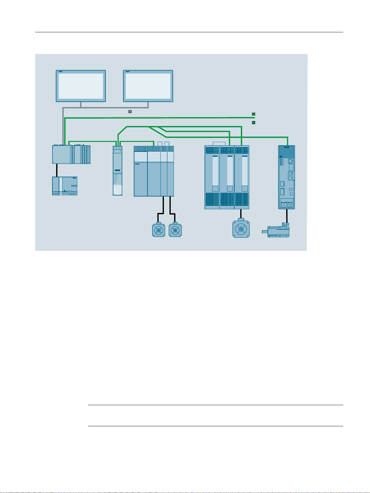
Servomotor
SIMOTICS S-1FK2
0DLQVSLQGOHPRWRU
6HUYRPRWRUV
2SHUDWRUSDQHOIURQWV
3RZHUVXSSO\
352),1(7,2
6,1$0,&66FKDVVLV
6,1$0,&66
%RRNVL]H
&8
0&8
6,1$0,&66
'LVSOD\3RUW
,QGXVWULDO(WKHUQHW
System overview
2.2 System configuration
Figure 2-1 Topology example
PROFINET
The SINUMERIK MCU 1720 offers integrated PROFINET functionality:
● PROFINET I/O for PLC peripherals
● PROFINET I/O for NCK peripherals (isochronous)
● PLC isochronous drives:
– MC technology objects
● PLC non-isochronous drives:
– Basic positioner function module
– Closed loop position control function module
● NCK isochronous and non-isochronous drives (also with Safety Integrated)
● PROFIsafe V2
Note
Precondition: TIA Portal as of V15
MCU 1720
Equipment Manual, 09/2019, A5E47437728B AB 13

System overview
2.3 Ordering data
As part of PROFINET, PROFINET IO is a communication concept that is used to implement
modular, distributed applications. PROFINET IO is based on Industrial Ethernet and allows
distributed field and I/O equipment to be connected to the central processing unit.
128 PROFINET IO devices can be operated on the MCU as an IO controller.
2.3 Ordering data
Table 2-1 Order data for system components
System component Article number
MCU 1720 with mounting rail 6FC5222-1AA00-0AA0
PP 72/48D PN I/O module 6FC5311-0AA00-0AA0
PP 72/48D 2/2A PN I/O module 6FC5311-0AA00-1AA0
USB FlashDrive 16 GB, USB 3.0 6ES7648-0DC60-0AA0
Ordering options
Table 2-2 Order data for mounting sets / spare parts / accessories
Mounting sets / spare parts / accessories Article number
Mounting rail brackets for rail mounting 6ES7648-1AA20-0YM1
Mounting bracket for portrait mounting 6ES7648-1AA20-0YP0
The described products can be found in the following catalogs:
● All the devices that belong to the SINUMERIK MC and SINAMICS S120 product families
can be found in Catalog NC 63. This catalog makes references to all other related catalogs.
You can also order the products online:
● Industry Mall: http://www.siemens.com/industrymall
● Spares On Web: http://workplace.automation.siemens.de/sparesonweb
MCU 1720
14 Equipment Manual, 09/2019, A5E47437728B AB

Fundamental safety instructions
3.1 General safety instructions
WARNING
Electric shock and danger to life due to other energy sources
Touching live components can result in death or severe injury.
● Only work on electrical devices when you are qualified for this job.
● Always observe the country-specific safety rules.
Generally, the following six steps apply when establishing safety:
1. Prepare for disconnection. Notify all those who will be affected by the procedure.
2. Isolate the drive system from the power supply and take measures to prevent it being
switched back on again.
3. Wait until the discharge time specified on the warning labels has elapsed.
4. Check that there is no voltage between any of the power connections, and between any of
the power connections and the protective conductor connection.
5. Check whether the existing auxiliary supply circuits are de-energized.
6. Ensure that the motors cannot move.
7. Identify all other dangerous energy sources, e.g. compressed air, hydraulic systems, or
water. Switch the energy sources to a safe state.
8. Check that the correct drive system is completely locked.
3
After you have completed the work, restore the operational readiness in the inverse sequence.
WARNING
Electric shock due to connection to an unsuitable power supply
When equipment is connected to an unsuitable power supply, exposed components may
carry a hazardous voltage. Contact with hazardous voltage can result in severe injury or death.
● Only use power supplies that provide SELV (Safety Extra Low Voltage) or PELV(Protective Extra Low Voltage) output voltages for all connections and terminals of the
electronics modules.
MCU 1720
Equipment Manual, 09/2019, A5E47437728B AB 15
Fundamental safety instructions
3.1 General safety instructions
WARNING
Electric shock due to equipment damage
Improper handling may cause damage to equipment. For damaged devices, hazardous
voltages can be present at the enclosure or at exposed components; if touched, this can result
in death or severe injury.
● Ensure compliance with the limit values specified in the technical data during transport,
storage and operation.
● Do not use any damaged devices.
WARNING
Electric shock due to unconnected cable shields
Hazardous touch voltages can occur through capacitive cross-coupling due to unconnected
cable shields.
● As a minimum, connect cable shields and the cores of cables that are not used at one end
at the grounded housing potential.
WARNING
Electric shock if there is no ground connection
For missing or incorrectly implemented protective conductor connection for devices with
protection class I, high voltages can be present at open, exposed parts, which when touched,
can result in death or severe injury.
● Ground the device in compliance with the applicable regulations.
WARNING
Spread of fire from built-in devices
In the event of fire outbreak, the enclosures of built-in devices cannot prevent the escape of
fire and smoke. This can result in serious personal injury or property damage.
● Install built-in units in a suitable metal cabinet in such a way that personnel are protected
against fire and smoke, or take other appropriate measures to protect personnel.
● Ensure that smoke can only escape via controlled and monitored paths.
MCU 1720
16 Equipment Manual, 09/2019, A5E47437728B AB
Fundamental safety instructions
3.1 General safety instructions
WARNING
Unexpected movement of machines caused by radio devices or mobile phones
When radio devices or mobile phones with a transmission power > 1 W are used in the
immediate vicinity of components, they may cause the equipment to malfunction.
Malfunctions may impair the functional safety of machines and can therefore put people in
danger or lead to property damage.
● If you come closer than around 2 m to such components, switch off any radios or mobile
phones.
● Use the "SIEMENS Industry Online Support app" only on equipment that has already been
switched off.
WARNING
Fire due to inadequate ventilation clearances
Inadequate ventilation clearances can cause overheating of components with subsequent fire
and smoke. This can cause severe injury or even death. This can also result in increased
downtime and reduced service lives for devices/systems.
● Ensure compliance with the specified minimum clearance as ventilation clearance for the
respective component.
NOTICE
Overheating due to inadmissible mounting position
The device may overheat and therefore be damaged if mounted in an inadmissible position.
● Only operate the device in admissible mounting positions.
WARNING
Unexpected movement of machines caused by inactive safety functions
Inactive or non-adapted safety functions can trigger unexpected machine movements that
may result in serious injury or death.
● Observe the information in the appropriate product documentation before commissioning.
● Carry out a safety inspection for functions relevant to safety on the entire system, including
all safety-related components.
● Ensure that the safety functions used in your drives and automation tasks are adjusted and
activated through appropriate parameterizing.
● Perform a function test.
● Only put your plant into live operation once you have guaranteed that the functions relevant
to safety are running correctly.
MCU 1720
Equipment Manual, 09/2019, A5E47437728B AB 17
Fundamental safety instructions
3.3 Warranty and liability for application examples
Note
Important safety notices for Safety Integrated functions
If you want to use Safety Integrated functions, you must observe the safety notices in the Safety
Integrated manuals.
3.2 Equipment damage due to electric fields or electrostatic discharge
Electrostatic sensitive devices (ESD) are individual components, integrated circuits, modules
or devices that may be damaged by either electric fields or electrostatic discharge.
NOTICE
Equipment damage due to electric fields or electrostatic discharge
Electric fields or electrostatic discharge can cause malfunctions through damaged individual
components, integrated circuits, modules or devices.
● Only pack, store, transport and send electronic components, modules or devices in their
original packaging or in other suitable materials, e.g conductive foam rubber of aluminum
foil.
● Only touch components, modules and devices when you are grounded by one of the
following methods:
– Wearing an ESD wrist strap
– Wearing ESD shoes or ESD grounding straps in ESD areas with conductive flooring
● Only place electronic components, modules or devices on conductive surfaces (table with
ESD surface, conductive ESD foam, ESD packaging, ESD transport container).
3.3 Warranty and liability for application examples
Application examples are not binding and do not claim to be complete regarding configuration,
equipment or any eventuality which may arise. Application examples do not represent specific
customer solutions, but are only intended to provide support for typical tasks.
As the user you yourself are responsible for ensuring that the products described are operated
correctly. Application examples do not relieve you of your responsibility for safe handling when
using, installing, operating and maintaining the equipment.
MCU 1720
18 Equipment Manual, 09/2019, A5E47437728B AB

3.4 Industrial security
Note
Industrial security
Siemens provides products and solutions with industrial security functions that support the
secure operation of plants, systems, machines and networks.
In order to protect plants, systems, machines and networks against cyber threats, it is
necessary to implement – and continuously maintain – a holistic, state-of-the-art industrial
security concept. Products and solutions from Siemens constitute one element of such a
concept.
Customers are responsible for preventing unauthorized access to their plants, systems,
machines and networks. Such systems, machines and components should only be connected
to an enterprise network or the Internet if and to the extent such a connection is necessary and
only when appropriate security measures (e.g. using firewalls and/or network segmentation)
are in place.
For additional information on industrial security measures that can be implemented, please
visit:
Fundamental safety instructions
3.4 Industrial security
Industrial security (https://www.siemens.com/industrialsecurity)
Siemens’ products and solutions undergo continuous development to make them more secure.
Siemens strongly recommends that product updates are applied as soon as they become
available, and that only the latest product versions are used. Use of product versions that are
no longer supported, and failure to apply the latest updates may increase customer’s exposure
to cyber threats.
To stay informed about product updates, subscribe to the Siemens Industrial Security RSS
Feed at:
Industrial security (https://www.siemens.com/industrialsecurity)
Further information is provided on the Internet:
Industrial Security Configuration Manual (https://support.industry.siemens.com/cs/ww/en/
view/108862708)
MCU 1720
Equipment Manual, 09/2019, A5E47437728B AB 19

Fundamental safety instructions
3.4 Industrial security
WARNING
Unsafe operating states resulting from software manipulation
Software manipulations, e.g. viruses, Trojans, or worms, can cause unsafe operating states
in your system that may lead to death, serious injury, and property damage.
● Keep the software up to date.
● Incorporate the automation and drive components into a holistic, state-of-the-art industrial
security concept for the installation or machine.
● Make sure that you include all installed products into the holistic industrial security concept.
● Protect files stored on exchangeable storage media from malicious software by with
suitable protection measures, e.g. virus scanners.
● On completion of commissioning, check all security-related settings.
● Protect the drive against unauthorized changes by activating the "Know-how protection"
converter function.
MCU 1720
20 Equipment Manual, 09/2019, A5E47437728B AB

3.5 Residual risks of power drive systems
When assessing the machine- or system-related risk in accordance with the respective local
regulations (e.g., EC Machinery Directive), the machine manufacturer or system installer must
take into account the following residual risks emanating from the control and drive components
of a drive system:
1. Unintentional movements of driven machine or system components during commissioning,
operation, maintenance, and repairs caused by, for example,
– Hardware and/or software errors in the sensors, control system, actuators, and cables
and connections
– Response times of the control system and of the drive
– Operation and/or environmental conditions outside the specification
– Condensation/conductive contamination
– Parameterization, programming, cabling, and installation errors
– Use of wireless devices/mobile phones in the immediate vicinity of electronic
components
– External influences/damage
Fundamental safety instructions
3.5 Residual risks of power drive systems
– X-ray, ionizing radiation and cosmic radiation
2. Unusually high temperatures, including open flames, as well as emissions of light, noise,
particles, gases, etc., can occur inside and outside the components under fault conditions
caused by, for example:
– Component failure
– Software errors
– Operation and/or environmental conditions outside the specification
– External influences/damage
3. Hazardous shock voltages caused by, for example:
– Component failure
– Influence during electrostatic charging
– Induction of voltages in moving motors
– Operation and/or environmental conditions outside the specification
– Condensation/conductive contamination
– External influences/damage
4. Electrical, magnetic and electromagnetic fields generated in operation that can pose a risk
to people with a pacemaker, implants or metal replacement joints, etc., if they are too close
5. Release of environmental pollutants or emissions as a result of improper operation of the
system and/or failure to dispose of components safely and correctly
6. Influence of network-connected communication systems, e.g. ripple-control transmitters or
data communication via the network
For more information about the residual risks of the drive system components, see the relevant
sections in the technical user documentation.
MCU 1720
Equipment Manual, 09/2019, A5E47437728B AB 21

Fundamental safety instructions
3.5 Residual risks of power drive systems
MCU 1720
22 Equipment Manual, 09/2019, A5E47437728B AB
Description
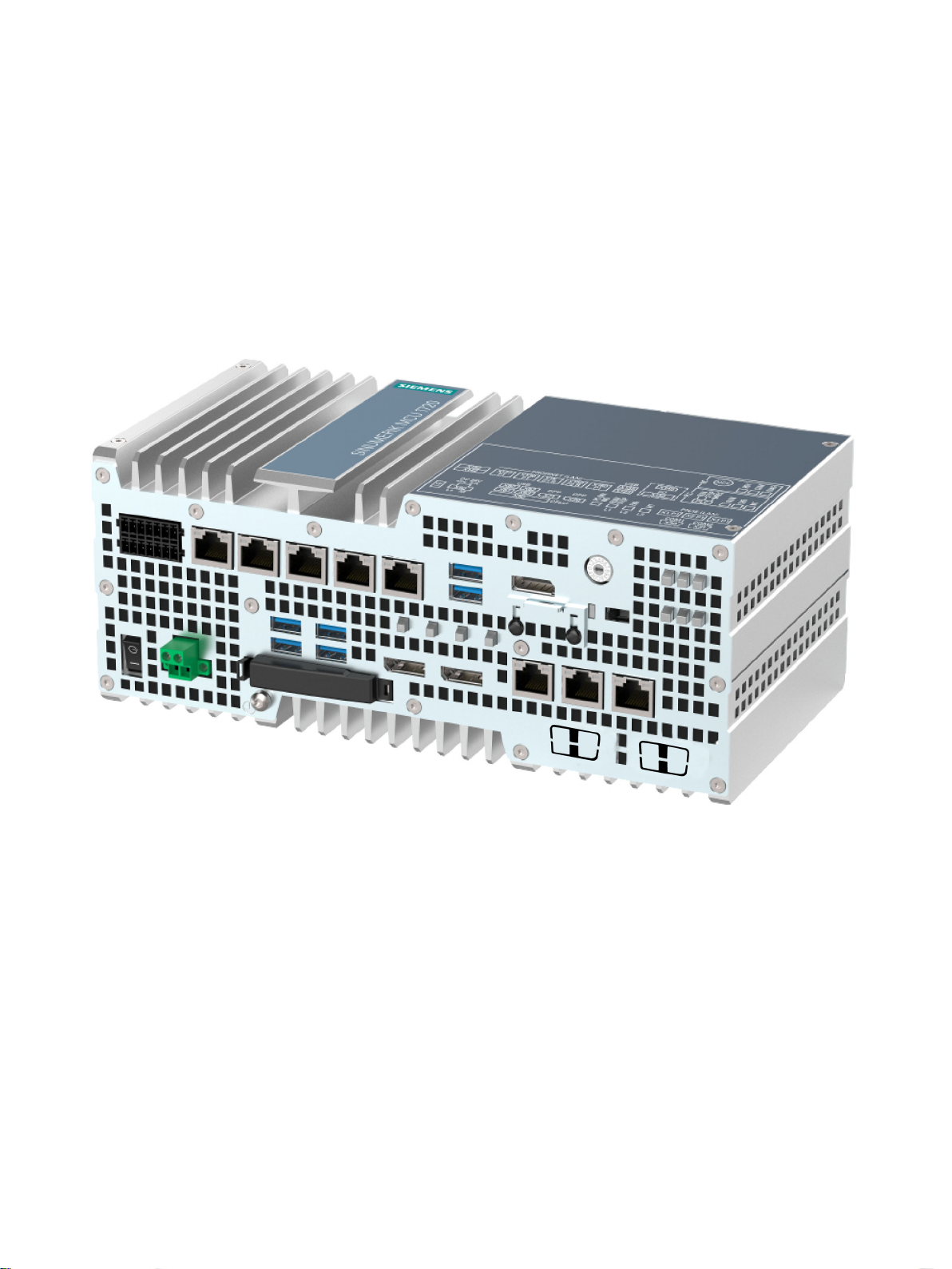
4.1 Characteristics
The software scalability – both from a CNC perspective and in terms of operation – means that
the SINUMERIK MCU1720 can be used in many domains. The possibilities range from simple
positioning tasks up to complex multi-axis systems.
4
The following elements characterize an MCU:
● Battery-backed real-time clock
● Slot for an SD Card
● Interfaces for operation:
– Ethernet interfaces
– PROFINET interfaces
– Digital inputs/outputs (6 of which can be parameterized as inputs for probes and BERO)
● Commissioning interfaces:
– Ethernet interface
MCU 1720
Equipment Manual, 09/2019, A5E47437728B AB 23
Description
4.1 Characteristics
Application areas and performance
On the MCU, the number of axes and/or the performance of the drive control can be increased
to 8 axes by using the MC technology objects. This is achieved by using the CU320.
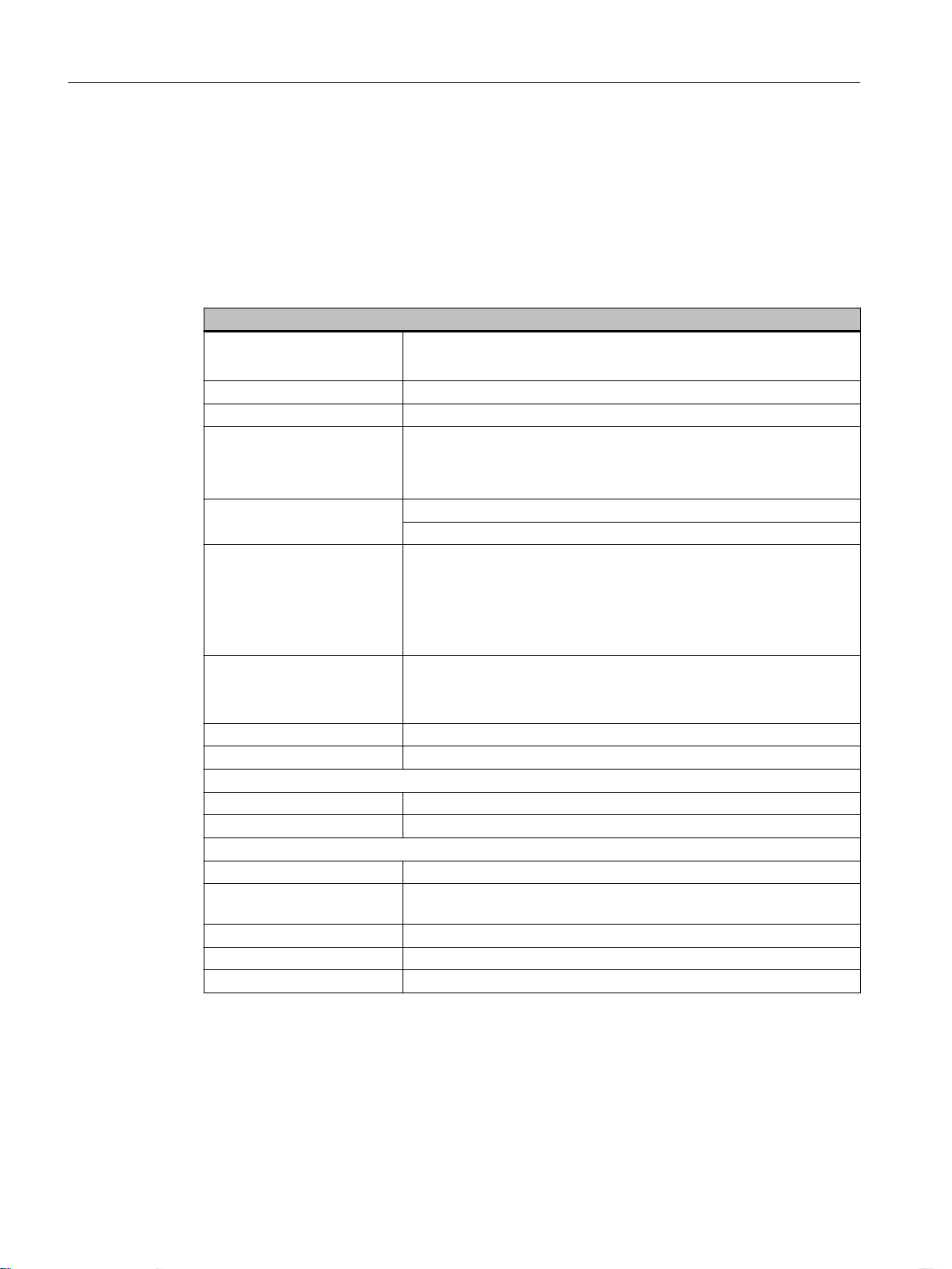
The following table lists the key characteristics and features of the MCU 1720:
Characteristics
Basic data
Mounting
Processor Intel® Core™ i5-6442EQ processor (6M cache, up to 2.7 GHz)
Main memory 8 GB DDR4-SDRAM SODIMM
Graphic
Power supply X80: 24 V DC (-15%/+20%) max. 5 A
Axes
Drives
Channels 4
Mode groups (BAG) 1
Drives and storage media
SSD (solid state disk) 2.5", ≥ 240 GB SATA
USB Stick Can be externally connected via USB interface
Interfaces
Graphic 2 x DisplayPorts DPP (DVI via DP++ to DVI adapter possible)
USB 6 × USB 3.0, max. 2 high current, can be operated simultaneously,
Ethernet 4 × RJ45 (10/100/1000 Mbit/s) teaming-capable
PROFINET 3 x RJ45 (10/100 Mbit/s) teaming-capable
Keyboard, mouse Can be connected via USB interface
● Attachment to DIN rail (horizontal mounting position)
● Portrait mounting (vertical mounting position)
● Intel® HD graphics 530
● 2 x DisplayPorts, maximum resolution 4096 x 2304 pixels
● Graphics memory is located in the main memory (dynamic UMA)
X142/X152: 24 V DC (-15%/+20%) max. 2 A
● Max. 8 CNC axes
● SIMATIC S7 Motion Control technology objects up to max. 2400
resources
● SINAMICS EPOS axes in regards to I/O addresses and
performance
● Max. 8 drives for CNC axes
● Max. 20 drives, controlled by SIMATIC S7 Motion Control
technology objects
downwardly compatible to USB 2.0/1.1
MCU 1720
24 Equipment Manual, 09/2019, A5E47437728B AB
Description
4.1 Characteristics
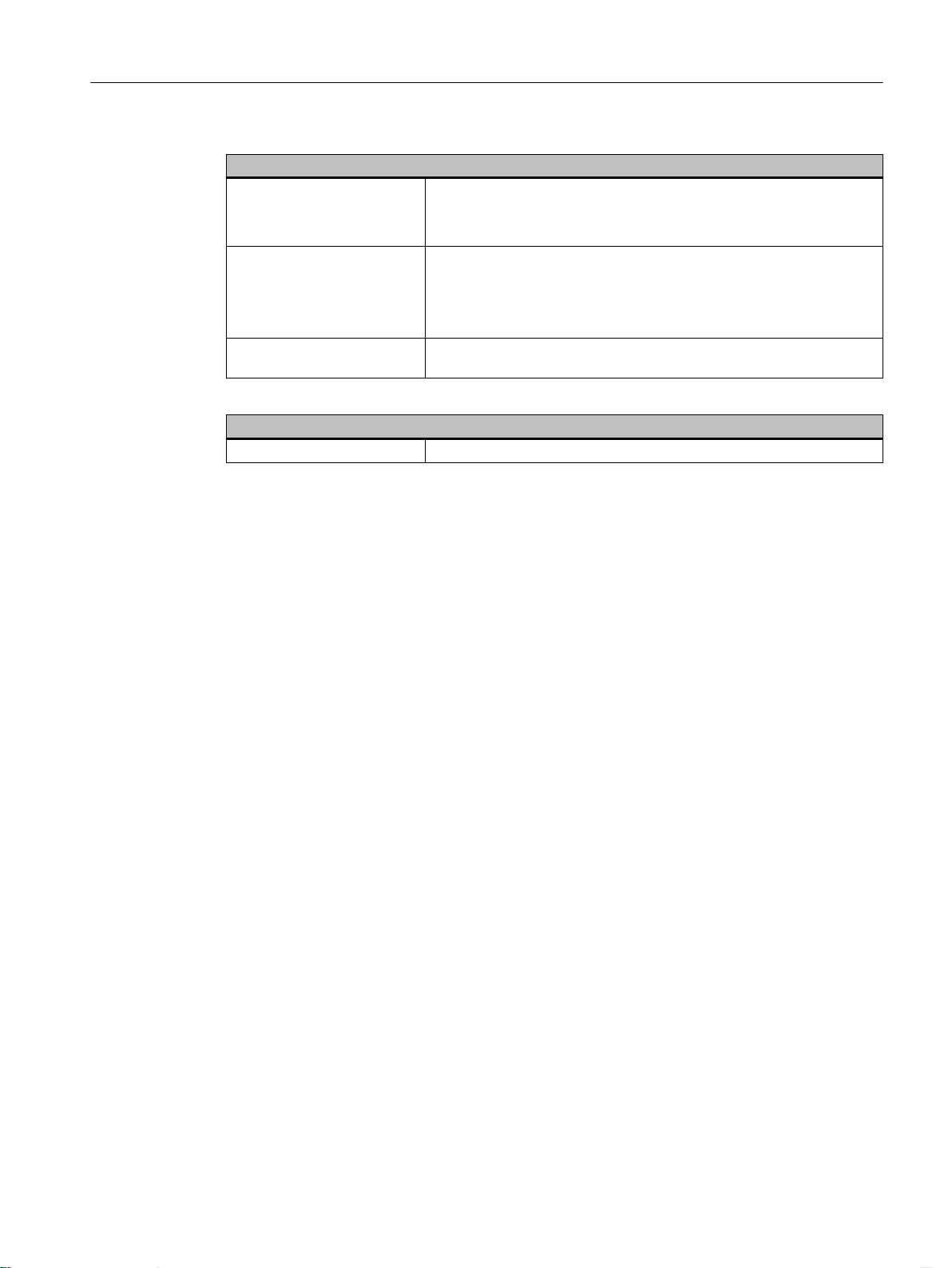
Extended device functions
Temperature monitoring
Watchdog
LED display 4 LEDs to display system states, of which 3 can be freely programmed
Software
Operating system Windows 10 IoT Enterprise LTSB 2016, 64 bit
● When the permissible temperature range is exceeded
● Alarm messages can be analyzed by the application program (local,
via LAN)
● Monitoring function for program execution
● Restart can be parameterized in the event of a fault
● Alarm messages can be analyzed by the application program (local,
via LAN)
by the user
MCU 1720
Equipment Manual, 09/2019, A5E47437728B AB 25
Description
4.2 Operator control and display elements
4.2 Operator control and display elements
4.2.1 Overview of operating and display elements
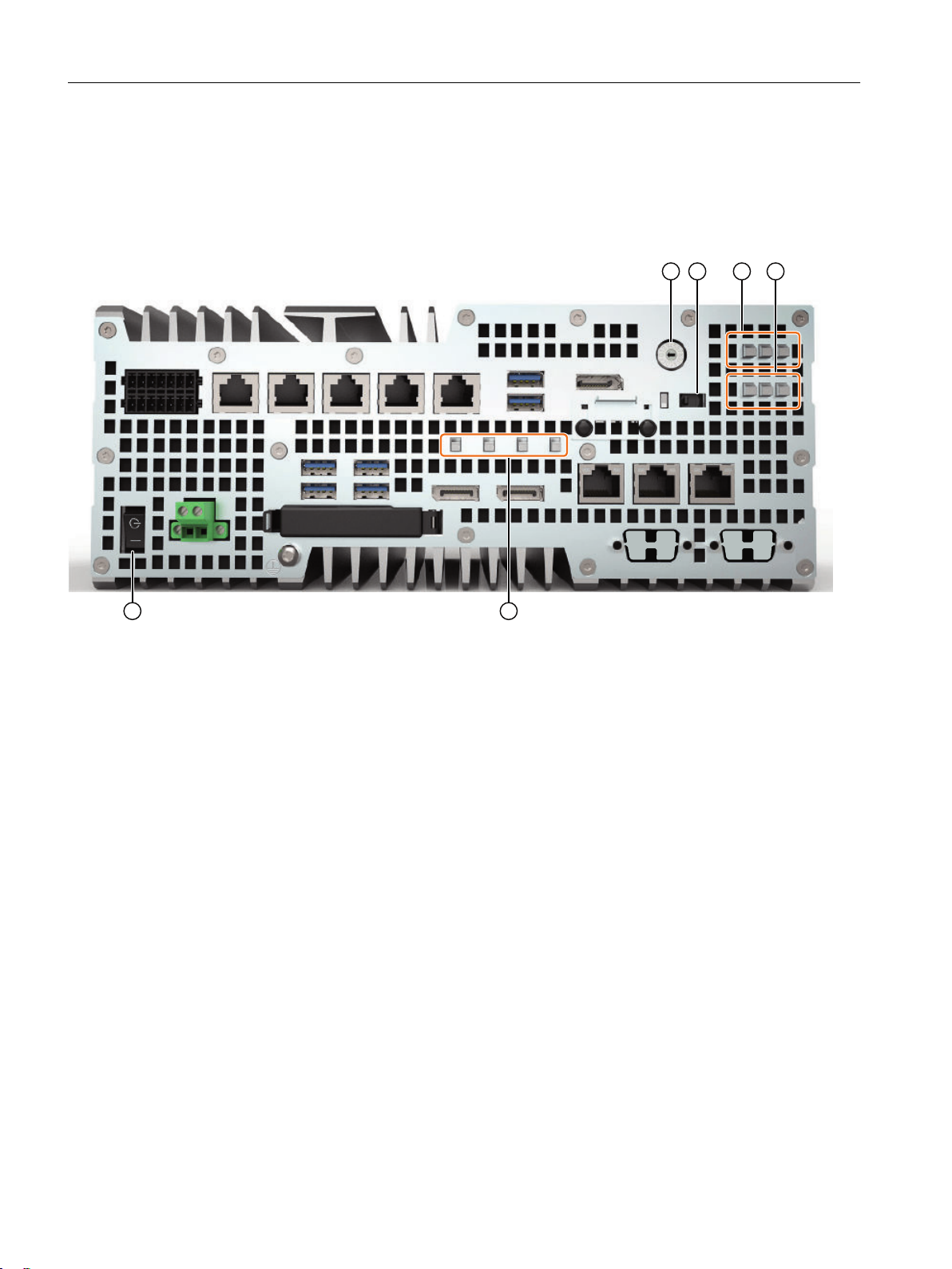
① NCK commissioning switch: Rotary switch with 16 positions
② PLC mode selector: Toggle switch with the settings RUN/STOP/MRES
③ LED display of the NC (RDY, COM, DIAG)
④ LED display of the PLC (RUN, ERR, MT)
⑤ LED display of the HMIs (PC ON/WD, RUN/STOP, ERR, MT and user LEDs L1/L2/L3)
⑥ On/off switch: The on/off switch does not isolate the device from the power supply. Position "ON" when the "_" symbol
is pressed. When delivered, it is in the "OFF" position.
Figure 4-1 Position of operator control and display elements
MCU 1720
26 Equipment Manual, 09/2019, A5E47437728B AB
4.2.2 LED displays
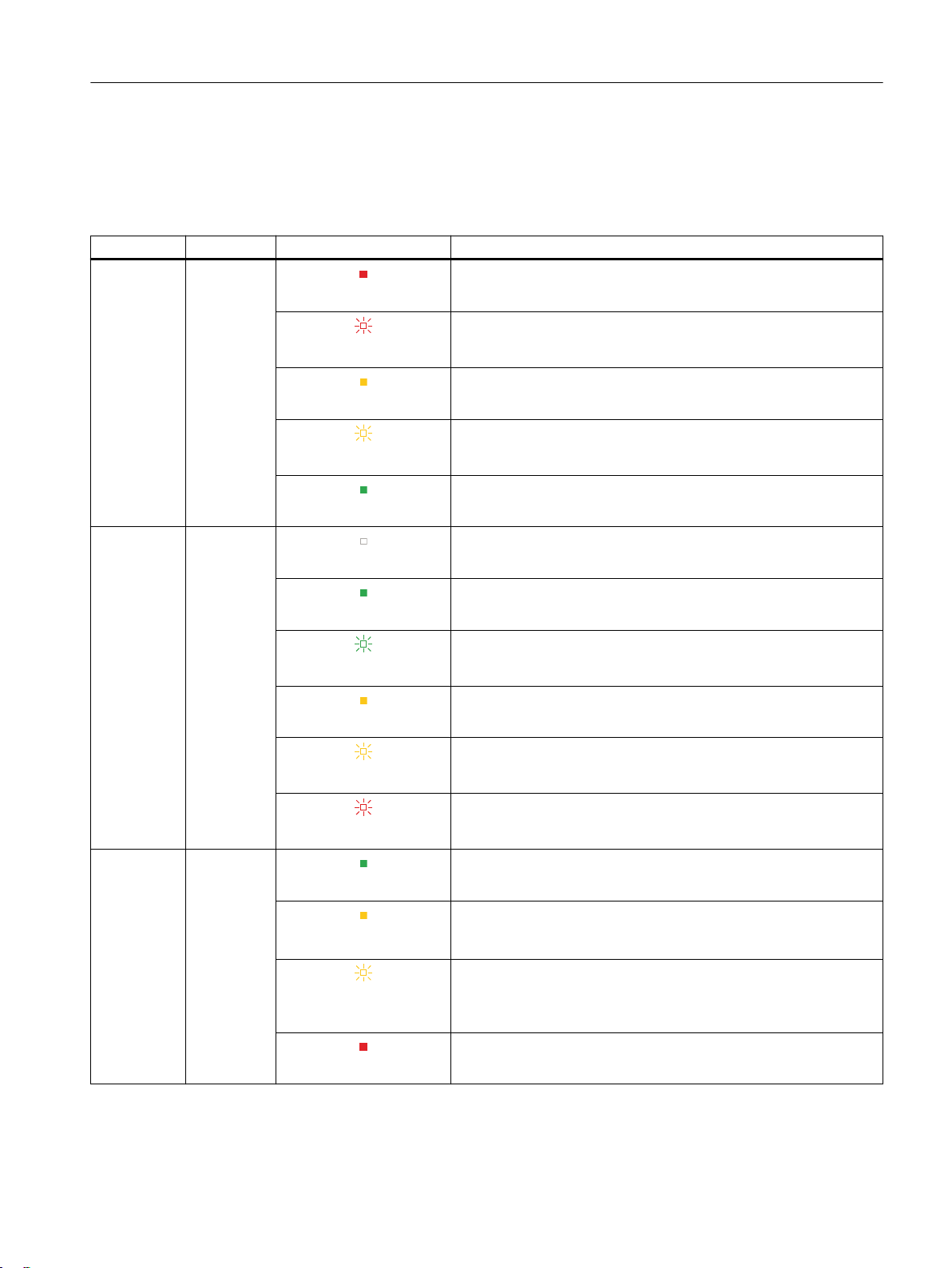
Meaning of the NC LEDs RDY, COM, DIAG and SD activity
Name Function Status Meaning
RDY Ready
COM Communi‐
cation
LED lights up red
LED flashes red (2 Hz)
LED lights up yellow
LED flashes yellow (2 Hz)
LED lights up green
LED off
At least one fault is active (e.g. RESET, watchdog monitoring etc.)
or the MCU is powering-up.
Not assigned (SINAMICS boot error).
The MCU powers up.
Firmware update is complete for components. Wait for POWER ON
for the components in question.
NC ramped up and everything in cyclic mode
CP not ramped up / started
Communication via CP possible (RUN operating state)
Description
4.2 Operator control and display elements
DIAG Diagnostics
LED lights up green
LED flashes green
LED lights up yellow
LED flashes yellow
LED flashes red
LED lights up green
LED lights up yellow
LED flashes yellow
(0.5 Hz)
LED lights up red
Communication possible (no configuration)
CP was stopped via PLC/TIA. No communication.
Configuration received and transition to the RUN operating state.
Error status (FATAL error)
Everything OK.
Software-related fault is pending, e.g. at PLC, HMI, Linux. Gener‐
ate the diagnostic data wit the Diag button and so contact the Hot‐
line.
The data backup operation initiated with the Diag button is running.
HW-related tests fail, e.g. memory test during switch on.
If no change occurs after multiple switch off/on, replace the device.
MCU 1720
Equipment Manual, 09/2019, A5E47437728B AB 27
Description
4.2 Operator control and display elements
Name Function Status Meaning
SD Activity
LED
(directly on
the card slot)
LED off
LED flashes yellow
SD card not inserted or inactive.
Active access to SD card
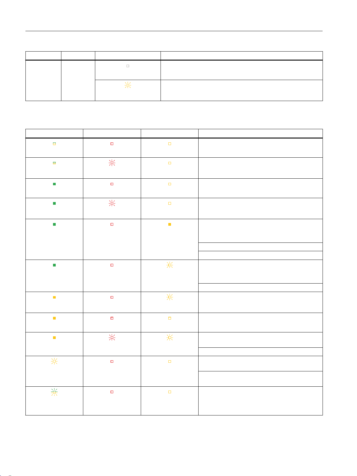
Meaning of the RUN/STOP, ERROR and MAINT PLC-LEDs
RUN/STOP LED ERROR LED MAINT LED Meaning
Supply voltage at the CPU not present or too low.
LED off LED off LED off
An error has occurred.
LED off
LED lights up green LED off LED off
LED lights up green
LED lights up green LED off LED lights up yellow
LED lights up green LED off
LED lights up yellow LED off
LED lights up yellow LED off LED off
LED lights up yellow
LED flashes yellow
LED flashes red
LED flashes red
LED flashes red LED flashes yellow
LED off LED off
LED off
LED off
LED flashes yellow
LED flashes yellow
The CPU is in the RUN operating state.
Diagnostic event pending.
A plant maintenance request is pending.
The affected hardware must be validated/replaced
within a short interval.
Active force job
PROFIenergy pause
A plant maintenance requirement is pending.
The affected hardware must be validated/replaced
within a foreseeable interval.
Configuration faulty
Firmware update completed successfully.
CPU is in STOP operating state.
The program on the SIMATIC Memory Card cau‐
ses a fault.
CPU defective
CPU performs internal activities during STOP, e.g.
ramp-up after STOP.
Downloading the user program from the SIMATIC
Memory Card
Startup (transition from RUN → STOP)
LED flashes
yellow/green
LED off LED off
MCU 1720
28 Equipment Manual, 09/2019, A5E47437728B AB
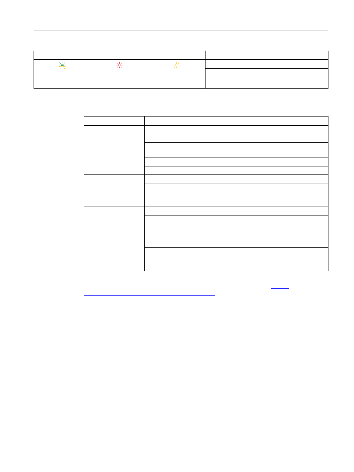
4.2 Operator control and display elements
RUN/STOP LED ERROR LED MAINT LED Meaning
Startup (booting the CPU)
LED flashes
yellow/green
LED flashes red LED flashes yellow
Test the LEDs during startup, insert a module.
LED flash test
Meanings of the HMI LEDs
LED Status Description
PC ON/WD Off -
Green BIOS ready to boot; PC is running
Flashing green/yellow
(1 Hz)
Yellow Idle state
Flashing red (1 Hz) Watchdog status display: Active
RUN/STOP or L1 Off -
Green Can be controlled from the user program
Yellow Can be controlled from the control program
ERROR or L2 Off -
Red Flashing red Can be controlled from the user program or the
MAINT or L3 Off -
Yellow Red Can be controlled from the control program
BIOS in POST, power switch on
(e.g. WinAC)
control program (e.g. WinAC)
(e.g. WinAC)
Description
You can find program examples to control LEDs under the Windows operating systems at the
Customer Support page Industry Automation and Drive Technologies. (https://
support.industry.siemens.com/cs/start?lc=en-WW)
Important LED states
● If all the LEDs are flashing, the PLC must be reset (general reset) via the mode selector
switch (ramp-up with the switch in the "MRES" position).
● While the MCU is powering up, all LEDs briefly light up orange. You can carry out a detailed
diagnosis using a PG/PC and the operating software.
Further information
You can find more information about LED states during ramp-up here:
● Commissioning Manual, Basic Software and Operating Software
You can find more information about the drive faults and alarms here:
● List manual (LH1) SINAMICS S120/S150
MCU 1720
Equipment Manual, 09/2019, A5E47437728B AB 29
Description
4.2 Operator control and display elements
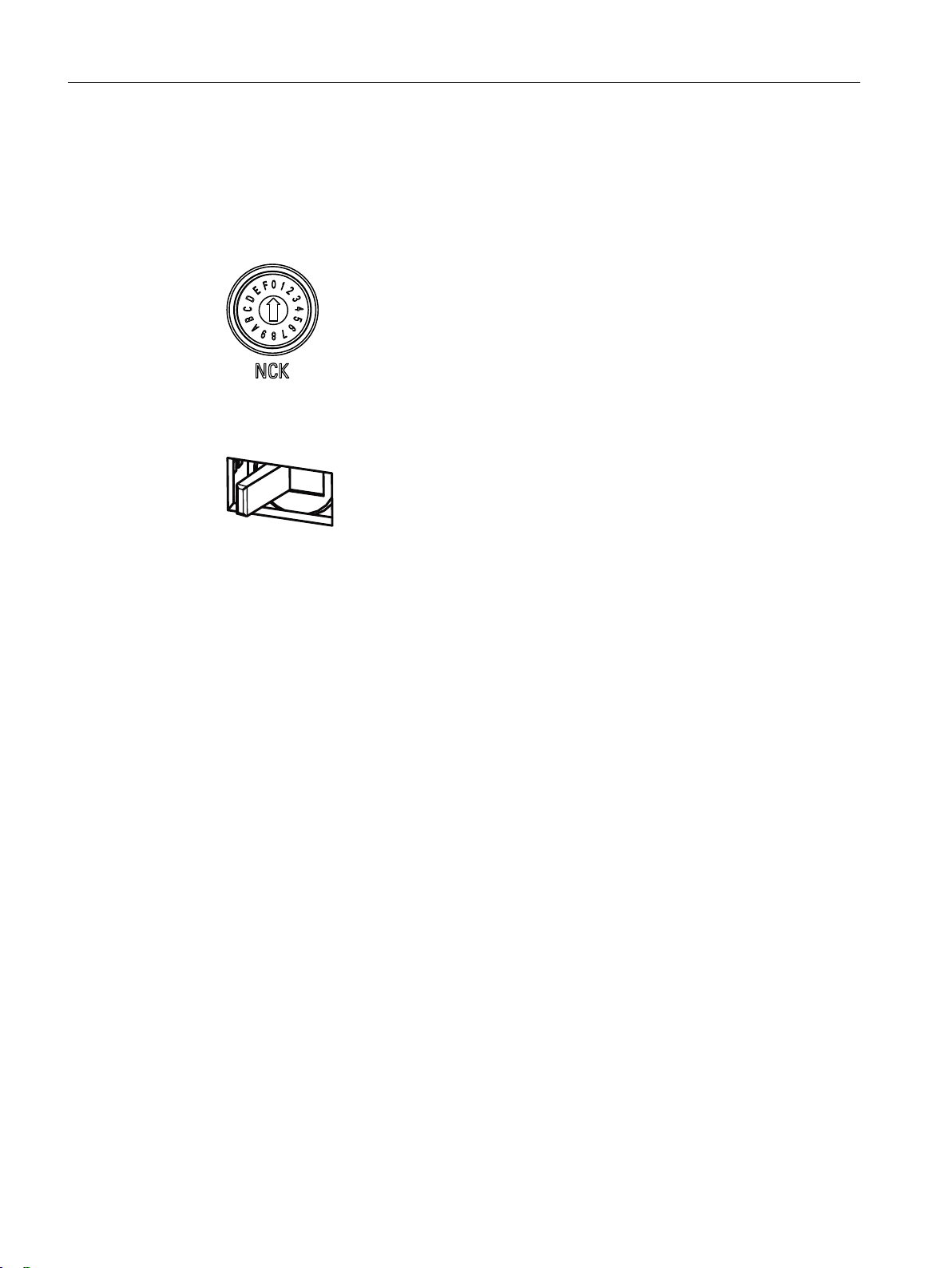
4.2.3 Start-up and mode selector switch
The MCU is equipped with an NCK rotary coding switch and a PLC mode selector switch as a
toggle switch with three switch positions:
● The NCK commissioning switch:
Setting during normal operation: "0"
Figure 4-2 NCK commissioning switch
● The PLC mode selector switch:
Setting during normal operation: "Run"
Further information
RUN Places the PLC in the RUN operating state.
STOP Places the PLC in the STOP operating state.
MRES Initiates the PLC reset.
Figure 4-3 PLC mode selector switch
You can find further information at:
● CNC Commissioning Manual Part 1 (NCK, PLC, drive)
MCU 1720
30 Equipment Manual, 09/2019, A5E47437728B AB
 Loading...