

Siemens SINUMERIK FM-NC, SIMODRIVE 611 digital, SINUMERIK 840Di, SINUMERIK 810D, SINUMERIK 840D Installation And Startup Manual

SINUMERIK 840D/
SIMODRIVE 611 digital
Installation and Start-Up Guide 04.2000 Edition
Manufacturer/Service Documentation
Overview of SINUMERIK 840D/840Di/810D/FM-NC Documentation (04.00)
General Documentation
SINUMERIK
840D/810D/
FM-NC
Brochure Catalog
SINUMERIK
840D/840Di/
810D/
FM-NC/611
Ordering Info
NC 60.1 *)
Technical Info.
NC 60.2
User Documentation
SINUMERIK
840D/840Di/
810D/
FM-NC
Program. Guide
– Short Guide
– Fundamentals *)
– Advanced *)
– Cycles
– Measuring Cycles
SINUMERIK
840D/810D
Operator’s Guide
– ManualTurn
– Short Guide ManualTurn
– ShopMill
– Short Guide ShopMill
SINUMERIK
SIROTEC
SIMODRIVE
Accessories
Catalog
Accessories NC-Z
SINUMERIK
840Di
System Overview
User Documentation
SINUMERIK
840D/810D/
FM-NC
AutoTurn
– Short Guide
– Programming (1)
– Setup (2)
SINUMERIK
840D/810D
Operator’s Guide
– Unit
Operator Panel
– HPU
– HT 6
SINUMERIK
840D/840Di/
810D/
FM-NC
Diagnostics
Guide *)
Manufacturer / Service Documentation
SINUMERIK
840D/810D
Description of
Functions
– ManualTurn
– ShopMill
SINUMERIK
840D/840Di/
810D
Description of
Functions
Synchronized
Actions
Wood, Glass,
Ceramics
SINUMERIK
840D/810D
Descr. of Functions
– Computer Link
– Tool Data
Information
System
SINUMERIK
840D/810D/
FM-NC
Operator’sGuide
– Short Guide
– Operator’s
Guide *)
SINUMERIK
Configuring
(HW) *)
– FM-NC
– 810D
– 840D
Manufacturer / Service Documentation
SINUMERIK
840D/840Di/
810D/
FM-NC
Operator
Components
(HW) *)
SINUMERIK
SIMODRIVE
611D
840D/810D
Description of
Functions
Drive Functions *)
SINUMERIK
840D/840Di/
810D/
FM-NC
Description of
Functions
– Basic Machine *)
– Extended Functions
– Special Functions
Manufacturer / Service Documentation
SINUMERIK
SIMODRIVE
Description of
Functions
SINUMERIK
Safety Integrated
SINUMERIK
840D
Description of
Functions
Digitizing
SINUMERIK
SIMODRIVE
Installation &
Start-up Guide *)
– FM-NC
– 810D
– 840D/611D
– MMC
Electronic Documentation
SINUMERIK
840D/810D/
FM-NC
Configuring Kit
MMC100/101
– Configuring
Syntax
– Development Kit
SINUMERIK
SIMODRIVE
840D/840Di/
810D
FM-NC
611D
Lists *)
SINUMERIK
840D/810D/
FM-NC
Screen Kit
MMC100/101
SW Update and
Configuration
SINUMERIK
SIMODRIVE
840D
611D
Description of
Functions
Linear Motor
SINUMERIK
840D/810D
Description of
Functions
Tool Management
SINUMERIK
SIMODRIVE
840D
611D
Description of
Functions
– Hydraulics
Module
– Analog Module
Manufacturer/Service Documentation
SINUMERIK
840D/810D/
FM-NC
Description of
Functions
Operator Interface
OP 030
SINUMERIK
SIMODRIVE
SIROTEC
EMC
Guidelines
SINUMERIK
SIMODRIVE
840D/810D/
FM-NC
611,
Motors
DOC ON CD *)
The SINUMERIK System
*) These documents are a minimum requirement for the control
SINUMERIK
840D/810D
Descr. of Functions
ISO Dialects for
SINUMERIK
SINUMERIK
Descr. of Functions
CAM Integration
DNC NT–2000
SINUMERIK
840Di
Manual
(HW + Installation
and Start-up)

General Preparations 1
Configuration 2
Settings, MPI/OPI 3
EMC/ESD Measures 4
SINUMERIK 840D
SIMODRIVE 611D
Installation and Start-Up Guide
Power On and Power Up 5
Parameterization of
Control
PLC Program 6
PLC Start-Up 7
Alarm and Message Texts 8
Axis/Spindle Dry Run 9
Drive Optimization 10
Data Backup 11
SW/HW Replacement 12
Valid for
Control Software Version
SINUMERIK 840D 5
SINUMERIK 840DE (export version) 5
Drive
SIMODRIVE 611D 4
04.00 Edition
MMC 13
Miscellaneous 14
Abbreviations A
References B
Index

y
3ls
SINUMERIK documentation
Printing history
Brief details of this edition and previous editions are listed below.
The status of each edition is shown by the code in the “Remarks” column.
Status code in the “Remarks” column:
A New documentation.. . . . .
B Unrevised reprint with new Order No.. . . . .
C Revised edition with new status. . . . . .
If factual changes have been made on the page since the last edition,
this is indicated by a new edition coding in the header on that page.
Edition Order No. Remarks
06.94 6FC5 297–0AB10–0BP0 A
08.94 6FC5 297–0AB10–0BP1 C
02.95 6FC5 297–2AB10–0BP0 C
04.95 6FC5 297–2AB10–0BP1 C
09.95 6FC5 297–3AB10–0BP0 C
03.96 6FC5 297–3AB10–0BP1 C
08.97 6FC5 297–4AB10–0BP0 C
12.97 6FC5 297–4AB10–0BP1 C
12.98 6FC5 297–5AB10–0BP0 C
08.99 6FC5 297–5AB10–0BP1 C
04.00 6FC5 297–5AB10–0BP2 C
This manual is included in the documentation available on CD-ROM (DOCONCD)
Edition Order No. Remarks
04.00 6FC5 298–5CA00–0BG2 C
Trademarks
SIMATICr, SIMATIC HMIr, SIMATIC NETr, SIROTECr, SINUMERIKr and SIMODRIVEr are Siemens
trademarks. The other designations in this publication may also be trade marks, the use of which by third
parties may constitute copyright violation.
Further information is available on the Internet under:
http://www.ad.siemens.de/sinumerik
This publication was produced with Interleaf V 7.
The reproduction, transmission or use of this document or its
contents is not permitted without express written authority. Offenders
will be liable for damages. All rights, including rights created by patent
grant or registration of a utility model or design, are reserved.
Siemens AG 1994 – 2000. All rights reserved.
Printed in the Federal Republic of German
Other functions not described in this documentation might be
executable in the control. This does not, however, represent an
obligation to supply such functions with a new control or when
servicing.
We have checked that the contents of this document correspond to
the hardware and software described. Nonetheless, differences might
exist. The information contained in this document is, however,
reviewed regularly and any necessary changes will be included in the
edition. We welcome suggestions for improvement.
Subject to technical changes without prior notice.
Siemens–AktiengesellschaftOrder No. 6FC5 297–5AB10–0BP2

03.96
PREFACE
SINUMERIK 840D Installation and Start-Up Guide
Preface
Structure of
documentation
Target group
Objective
Standard scope
The SINUMERIK documentation is divided into 3 different levels:
S General documentation
S User Documentation
S Manufacturer/Service Documentation
This document is intended for the manufacturers of machine tools incorporating
SINUMERIK 840D and SIMODRIVE 611D systems.
The Installation and Start-Up Guide provides all the relevant information
required for start-up, installation and servicing.
This document provides information about the control system design and the
interfaces of the individual components. It also describes the start-up and
installation procedure for SINUMERIK 840D with SIMODRIVE 611D including a
list of all data, signals and PLC blocks.
For detailed information about individual functions, function assignment and
performance data of individual components, please refer to the appropriate
document for the subject concerned (e.g. manuals, function descriptions etc.).
User-oriented activities such as the creation of part programs and control
operating procedures are described in detail in separate documents.
Separate descriptions are likewise provided of the tasks to be performed by the
tool manufacturer such as configuring, design and PLC programming.
Searching aids
In addition to the table of contents and indexes of figures and tables, we have
provided the following information in the appendix for your assistance:
1. Index of abbreviations
2. List of references
3. Index
For a complete list and description of SINUMERIK 840D alarms, please refer to
References: /DA/, Diagnostics Guide
For further useful information on start-up and troubleshooting, please refer to
References: /FB/, D1, “Diagnostics Tools”
Siemens AG 2000 All Rights Reserved
SINUMERIK 840D Installation and Start-Up Guide (IAD) – 04.00 Edition
v
SINUMERIK 840D Installation and Start-Up Guide
Preface
03.96
Symbols
The following symbols with special significance are used in the documentation:
Note
This symbol appears in this document to draw your attention to information
relevant to the subject in hand.
Important
!
This symbol appears in this document to draw your attention to an important
item of information.
Order data option
In this document, you will encounter the symbol shown on the left with a
reference to an ordering data option. Please note that the function described
can operate only if the specified option is installed in the control system.
Warnings
The following warnings with varying levels of severity are used in this document:
Danger
!
!
!
This symbol indicates that death, grievous injury or substantial property damage will occur if the appropriate precautions are not taken.
Caution
This symbol indicates minor injuries or property damage may occur if the appropriate precautions are not taken.
Warning
This symbol indicates that death, grievous injury or substantial property damage may occur if the appropriate precautions are not taken.
vi
SINUMERIK 840D Installation and Start-Up Guide (IAD) – 04.00 Edition
Siemens AG 2000 All Rights Reserved

03.96
Technical information
SINUMERIK 840D Installation and Start-Up Guide
Preface
Trademarks
Notation
Effectiveness of
changes
IBM is a registered trademark of the International Business Corporation.
MS–DOS
Corporation.
The following notation and abbreviations are used in this document:
and WINDOWST are registered trademarks of the Microsoft
S PLC interface signals –> IS “Signal name” (signal data)
Examples:
– IS “MMC–CPU1 ready” (DB10, DBX108.2), i.e. the signal is stored in
data block 10, data byte 108, bit 2.
– IS “Feedrate/spindle override” (DB31–48, DBB0), i.e. the signals are
stored for specific spindles/axes in data blocks 31 to 48, data block
byte 0.
S Machine data –> MD: MD_NAME (English designation)
S Setting data –> SD: SD_NAME (English designation)
S The character “” means “corresponds to”.
After data (e.g. machine data) have been changed, it must also be noted when
the change will become effective (e.g. after power ON or immediately). This information is therefore always provided.
Siemens AG 2000 All Rights Reserved
SINUMERIK 840D Installation and Start-Up Guide (IAD) – 04.00 Edition
vii

SINUMERIK 840D Installation and Start-Up Guide
Preface
Notes
04.00
03.96
viii
SINUMERIK 840D Installation and Start-Up Guide (IAD) – 04.00 Edition
Siemens AG 2000 All Rights Reserved

Contents
1 General Preparations 1-15. . . . . . . . . . . . . . . . . . . . . . . . . . . . . . . . . . . . . . . . . . . . . . . .
1.1 Preconditions 1-15. . . . . . . . . . . . . . . . . . . . . . . . . . . . . . . . . . . . . . . . . . . . . . .
1.2 Standard/export version 1-16. . . . . . . . . . . . . . . . . . . . . . . . . . . . . . . . . . . . . .
2 Configuration 2-19. . . . . . . . . . . . . . . . . . . . . . . . . . . . . . . . . . . . . . . . . . . . . . . . . . . . . . .
2.1 Mechanical configuration 2-20. . . . . . . . . . . . . . . . . . . . . . . . . . . . . . . . . . . . .
2.1.1 Overview 2-20. . . . . . . . . . . . . . . . . . . . . . . . . . . . . . . . . . . . . . . . . . . . . . . . . . .
2.1.2 Mains infeed module 2-21. . . . . . . . . . . . . . . . . . . . . . . . . . . . . . . . . . . . . . . . .
2.1.3 NCU 2-22. . . . . . . . . . . . . . . . . . . . . . . . . . . . . . . . . . . . . . . . . . . . . . . . . . . . . . .
2.1.4 General configuration of SINUMERIK 840D system 2-23. . . . . . . . . . . . . .
2.2 Electrical configuration 2-23. . . . . . . . . . . . . . . . . . . . . . . . . . . . . . . . . . . . . . .
2.2.1 Component connections 2-23. . . . . . . . . . . . . . . . . . . . . . . . . . . . . . . . . . . . . .
2.2.2 Connection of mains infeed module (U/E, I/RF) 2-25. . . . . . . . . . . . . . . . . .
2.2.3 Motor connection 2-28. . . . . . . . . . . . . . . . . . . . . . . . . . . . . . . . . . . . . . . . . . . .
2.2.4 Encoder connection 2-29. . . . . . . . . . . . . . . . . . . . . . . . . . . . . . . . . . . . . . . . . .
2.2.5 Connection of MMC100 and MMC102/103 2-30. . . . . . . . . . . . . . . . . . . . . .
2.2.6 Configuration of components for digitizing 2-32. . . . . . . . . . . . . . . . . . . . . . .
3 Settings, MPI / OPI 3-35. . . . . . . . . . . . . . . . . . . . . . . . . . . . . . . . . . . . . . . . . . . . . . . . . . .
3.1 MPI/OPI, network rules 3-36. . . . . . . . . . . . . . . . . . . . . . . . . . . . . . . . . . . . . . .
3.2 Standard configuration 3-38. . . . . . . . . . . . . . . . . . . . . . . . . . . . . . . . . . . . . . .
3.2.1 Standard configuration up to SW 3.1 3-38. . . . . . . . . . . . . . . . . . . . . . . . . . .
3.2.2 Standard configuration as from SW 3.2 3-40. . . . . . . . . . . . . . . . . . . . . . . . .
3.3 Connection of a 2nd MCP/customer operator panel interface
and/or 1 HHU (up to SW 3.1) 3-43. . . . . . . . . . . . . . . . . . . . . . . . . . . . . . . . . .
3.3.1 Connection to OPI bus 3-44. . . . . . . . . . . . . . . . . . . . . . . . . . . . . . . . . . . . . . .
3.3.2 Connection to MPI bus 3-45. . . . . . . . . . . . . . . . . . . . . . . . . . . . . . . . . . . . . . .
3.3.3 Example of a configuration of MCP and HHU via OPI 3-46. . . . . . . . . . . . .
3.3.4 Example of a configuration of HHU via MPI 3-47. . . . . . . . . . . . . . . . . . . . . .
3.4 Handheld unit 3-52. . . . . . . . . . . . . . . . . . . . . . . . . . . . . . . . . . . . . . . . . . . . . . .
3.4.1 Settings on the HHU up to software version 3.x 3-52. . . . . . . . . . . . . . . . . .
3.4.2 Settings on the HHU for software version 4.x and higher 3-53. . . . . . . . . .
3.4.3 Configuring the HHU, setting interface parameters 3-53. . . . . . . . . . . . . . .
3.4.4 Example: Connecting the HHU to the SINUMERIK 840D 3-55. . . . . . . . . .
3.5 Handheld programming unit 3-56. . . . . . . . . . . . . . . . . . . . . . . . . . . . . . . . . . .
3.5.1 Interface signals of the HPU 3-57. . . . . . . . . . . . . . . . . . . . . . . . . . . . . . . . . . .
3.5.2 Standard configuration of the HPU (without MCP) 3-58. . . . . . . . . . . . . . . .
3.5.3 Deviations from the standard HPU configuration
(up to SW 3.1) 3-59. . . . . . . . . . . . . . . . . . . . . . . . . . . . . . . . . . . . . . . . . . . . . .
3.6 Machine control panel (MCP) 3-66. . . . . . . . . . . . . . . . . . . . . . . . . . . . . . . . . .
3.7 Customer operator panel interface 3-68. . . . . . . . . . . . . . . . . . . . . . . . . . . . .
Siemens AG 2000 All Rights Reserved
SINUMERIK 840D Installation and Start-Up Guide (IAD) – 04.00 Edition
ix

SINUMERIK 840D Installation and Start-Up Guide
Contents
3.8 Second machine control panel 3-69. . . . . . . . . . . . . . . . . . . . . . . . . . . . . . . . .
3.9 MMC 100/MMC 102/103 operator panel 3-69. . . . . . . . . . . . . . . . . . . . . . . .
3.9.1 Settings on the MMC 3-69. . . . . . . . . . . . . . . . . . . . . . . . . . . . . . . . . . . . . . . . .
3.9.2 Language default 3-70. . . . . . . . . . . . . . . . . . . . . . . . . . . . . . . . . . . . . . . . . . . .
4 EMC / ESD Measures 4-73. . . . . . . . . . . . . . . . . . . . . . . . . . . . . . . . . . . . . . . . . . . . . . . .
4.1 Measures to suppress interference 4-73. . . . . . . . . . . . . . . . . . . . . . . . . . . . .
4.2 Measures to protect ESD-sensitive components 4-74. . . . . . . . . . . . . . . . .
5 Power On and Power-Up 5-75. . . . . . . . . . . . . . . . . . . . . . . . . . . . . . . . . . . . . . . . . . . . .
5.1 Startup sequence 5-76. . . . . . . . . . . . . . . . . . . . . . . . . . . . . . . . . . . . . . . . . . . .
5.2 Power on and power-up 5-77. . . . . . . . . . . . . . . . . . . . . . . . . . . . . . . . . . . . . .
5.2.1 Power on 5-78. . . . . . . . . . . . . . . . . . . . . . . . . . . . . . . . . . . . . . . . . . . . . . . . . . .
5.2.2 Power-up 5-78. . . . . . . . . . . . . . . . . . . . . . . . . . . . . . . . . . . . . . . . . . . . . . . . . . .
5.2.3 MMC100 – MMC102/103 power-up 5-80. . . . . . . . . . . . . . . . . . . . . . . . . . . .
5.2.4 Error during control power-up (NC) 5-82. . . . . . . . . . . . . . . . . . . . . . . . . . . . .
5.2.5 Machine control panel (MCP) power-up 5-84. . . . . . . . . . . . . . . . . . . . . . . . .
5.2.6 Drive system power-up 5-84. . . . . . . . . . . . . . . . . . . . . . . . . . . . . . . . . . . . . . .
5.2.7 MMC102/103 BIOS setup 5-84. . . . . . . . . . . . . . . . . . . . . . . . . . . . . . . . . . . . .
04.00
03.96
6 Assigning Parameters to the Control and the PLC Program 6-85. . . . . . . . . . . . .
6.1 Machine and setting data 6-87. . . . . . . . . . . . . . . . . . . . . . . . . . . . . . . . . . . . .
6.2 Handling machine and setting data 6-89. . . . . . . . . . . . . . . . . . . . . . . . . . . . .
6.3 Protection level concept 6-90. . . . . . . . . . . . . . . . . . . . . . . . . . . . . . . . . . . . . .
6.4 Machine data masking filter (SW 4.2 and higher) 6-92. . . . . . . . . . . . . . . . .
6.4.1 Function 6-92. . . . . . . . . . . . . . . . . . . . . . . . . . . . . . . . . . . . . . . . . . . . . . . . . . . .
6.4.2 Selecting and setting the machine data masking filters 6-92. . . . . . . . . . . .
6.4.3 Saving the filter settings 6-95. . . . . . . . . . . . . . . . . . . . . . . . . . . . . . . . . . . . . .
6.5 Example of start-up design concept 6-96. . . . . . . . . . . . . . . . . . . . . . . . . . . .
6.6 System data 6-99. . . . . . . . . . . . . . . . . . . . . . . . . . . . . . . . . . . . . . . . . . . . . . . .
6.6.1 Basic settings 6-99. . . . . . . . . . . . . . . . . . . . . . . . . . . . . . . . . . . . . . . . . . . . . . .
6.7 Memory configuration 6-102. . . . . . . . . . . . . . . . . . . . . . . . . . . . . . . . . . . . . . . .
6.7.1 Dynamic RAM memory 6-103. . . . . . . . . . . . . . . . . . . . . . . . . . . . . . . . . . . . . . .
6.7.2 Static RAM memory 6-104. . . . . . . . . . . . . . . . . . . . . . . . . . . . . . . . . . . . . . . . . .
6.8 Scaling machine data 6-106. . . . . . . . . . . . . . . . . . . . . . . . . . . . . . . . . . . . . . . .
6.9 Axes and spindles 6-108. . . . . . . . . . . . . . . . . . . . . . . . . . . . . . . . . . . . . . . . . . .
6.9.1 Description of the axis configuration 6-108. . . . . . . . . . . . . . . . . . . . . . . . . . . .
6.9.2 Drive configuration (FDD, SLM, MSD) 6-111. . . . . . . . . . . . . . . . . . . . . . . . . .
6.9.3 Setting the axis-specific setpoint/actual value parameters 6-114. . . . . . . . .
6.9.4 Drive parameterization (FDD, MSD) 6-116. . . . . . . . . . . . . . . . . . . . . . . . . . . .
6.9.5 Parameterization of incremental measuring systems 6-118. . . . . . . . . . . . . .
6.9.6 Parameterization of absolute measuring systems
(EnDat interface) 6-121. . . . . . . . . . . . . . . . . . . . . . . . . . . . . . . . . . . . . . . . . . . .
6.9.7 Overview of optimization drive parameters 6-124. . . . . . . . . . . . . . . . . . . . . .
6.9.8 Axis data 6-127. . . . . . . . . . . . . . . . . . . . . . . . . . . . . . . . . . . . . . . . . . . . . . . . . . .
6.9.9 Velocity matching (axis) 6-129. . . . . . . . . . . . . . . . . . . . . . . . . . . . . . . . . . . . . .
6.9.10 Position controller data (axis) 6-130. . . . . . . . . . . . . . . . . . . . . . . . . . . . . . . . . .
6.9.11 Monitoring functions (axis) 6-133. . . . . . . . . . . . . . . . . . . . . . . . . . . . . . . . . . . .
x
SINUMERIK 840D Installation and Start-Up Guide (IAD) – 04.00 Edition
Siemens AG 2000 All Rights Reserved

04.00
03.96
SINUMERIK 840D Installation and Start-Up Guide
6.9.12 Reference point approach (axis) 6-138. . . . . . . . . . . . . . . . . . . . . . . . . . . . . . .
6.9.13 Spindle data 6-140. . . . . . . . . . . . . . . . . . . . . . . . . . . . . . . . . . . . . . . . . . . . . . . .
6.9.14 Spindle configuration 6-142. . . . . . . . . . . . . . . . . . . . . . . . . . . . . . . . . . . . . . . . .
6.9.15 Encoder matching (spindle) 6-142. . . . . . . . . . . . . . . . . . . . . . . . . . . . . . . . . . .
6.9.16 Speeds and setpoint adjustment for spindle 6-144. . . . . . . . . . . . . . . . . . . . .
6.9.17 Spindle positioning 6-145. . . . . . . . . . . . . . . . . . . . . . . . . . . . . . . . . . . . . . . . . . .
6.9.18 Spindle synchronization 6-146. . . . . . . . . . . . . . . . . . . . . . . . . . . . . . . . . . . . . .
6.9.19 Spindle monitoring 6-148. . . . . . . . . . . . . . . . . . . . . . . . . . . . . . . . . . . . . . . . . . .
6.9.20 Example: Start-up of NCK I/O devices 6-150. . . . . . . . . . . . . . . . . . . . . . . . . .
6.10 Linear motors (1FN1 and 1FN3 motors) 6-152. . . . . . . . . . . . . . . . . . . . . . . . .
6.10.1 General information about starting up linear motors 6-152. . . . . . . . . . . . . . .
6.10.2 Start-up: Linear motor with one primary part 6-154. . . . . . . . . . . . . . . . . . . . .
6.10.3 Start-up: Linear motors with 2 identical primary parts 6-163. . . . . . . . . . . . .
6.10.4 Mounting dimensions 6-165. . . . . . . . . . . . . . . . . . . . . . . . . . . . . . . . . . . . . . . . .
6.10.5 Temperature sensors for 1FN1 and 1FN3 motors 6-166. . . . . . . . . . . . . . . .
6.10.6 Measuring system 6-169. . . . . . . . . . . . . . . . . . . . . . . . . . . . . . . . . . . . . . . . . . .
6.10.7 Parallel connection of linear motors 6-172. . . . . . . . . . . . . . . . . . . . . . . . . . . .
6.10.8 Test measurements on linear motor 6-174. . . . . . . . . . . . . . . . . . . . . . . . . . . .
6.11 AM / U/F function 6-176. . . . . . . . . . . . . . . . . . . . . . . . . . . . . . . . . . . . . . . . . . . .
Contents
6.12 System settings for power up, RESET and part program start 6-177. . . . . .
7 PLC Start-Up 7-181. . . . . . . . . . . . . . . . . . . . . . . . . . . . . . . . . . . . . . . . . . . . . . . . . . . . . . . .
7.1 PLC start-up 7-181. . . . . . . . . . . . . . . . . . . . . . . . . . . . . . . . . . . . . . . . . . . . . . . .
7.2 Overview of organization blocks, function blocks and DBs 7-184. . . . . . . . .
8 Alarm and Message Texts 8-185. . . . . . . . . . . . . . . . . . . . . . . . . . . . . . . . . . . . . . . . . . . .
8.1 Alarm and message texts 8-186. . . . . . . . . . . . . . . . . . . . . . . . . . . . . . . . . . . . .
8.1.1 Alarm text files for MMC 100 8-186. . . . . . . . . . . . . . . . . . . . . . . . . . . . . . . . . .
8.1.2 Alarm text files for MMC 102/103 8-188. . . . . . . . . . . . . . . . . . . . . . . . . . . . . .
8.1.3 Alarm text files for HPU 8-190. . . . . . . . . . . . . . . . . . . . . . . . . . . . . . . . . . . . . . .
8.1.4 Syntax for alarm text files 8-192. . . . . . . . . . . . . . . . . . . . . . . . . . . . . . . . . . . . .
8.1.5 Properties of alarm list 8-195. . . . . . . . . . . . . . . . . . . . . . . . . . . . . . . . . . . . . . . .
9 Axis and Spindle Dry Run 9-197. . . . . . . . . . . . . . . . . . . . . . . . . . . . . . . . . . . . . . . . . . . .
9.1 Preconditions 9-197. . . . . . . . . . . . . . . . . . . . . . . . . . . . . . . . . . . . . . . . . . . . . . .
9.2 Axis test run 9-198. . . . . . . . . . . . . . . . . . . . . . . . . . . . . . . . . . . . . . . . . . . . . . . .
9.3 Testing the spindle 9-200. . . . . . . . . . . . . . . . . . . . . . . . . . . . . . . . . . . . . . . . . . .
10 Drive Optimization with Start-Up Tool 10-203. . . . . . . . . . . . . . . . . . . . . . . . . . . . . . . . .
10.1 Instructions for use 10-204. . . . . . . . . . . . . . . . . . . . . . . . . . . . . . . . . . . . . . . . . . .
10.1.1 System requirements 10-205. . . . . . . . . . . . . . . . . . . . . . . . . . . . . . . . . . . . . . . . .
10.1.2 Installation 10-205. . . . . . . . . . . . . . . . . . . . . . . . . . . . . . . . . . . . . . . . . . . . . . . . . .
10.1.3 Starting the program 10-206. . . . . . . . . . . . . . . . . . . . . . . . . . . . . . . . . . . . . . . . .
10.1.4 Terminating the program 10-206. . . . . . . . . . . . . . . . . . . . . . . . . . . . . . . . . . . . . .
10.2 Measuring functions 10-207. . . . . . . . . . . . . . . . . . . . . . . . . . . . . . . . . . . . . . . . . .
10.3 Interface signals Traverse request and Motion enable drive test 10-209. . . .
10.4 Aborting measuring functions 10-210. . . . . . . . . . . . . . . . . . . . . . . . . . . . . . . . . .
10.5 Frequency response measurement 10-211. . . . . . . . . . . . . . . . . . . . . . . . . . . . .
Siemens AG 2000 All Rights Reserved
SINUMERIK 840D Installation and Start-Up Guide (IAD) – 04.00 Edition
xi

SINUMERIK 840D Installation and Start-Up Guide
Contents
10.5.1 Measurement of torque control loop 10-211. . . . . . . . . . . . . . . . . . . . . . . . . . . .
10.5.2 Measurement of speed control loop 10-212. . . . . . . . . . . . . . . . . . . . . . . . . . . .
10.5.3 Measurement of position control loop 10-216. . . . . . . . . . . . . . . . . . . . . . . . . . .
10.6 Graphic display 10-219. . . . . . . . . . . . . . . . . . . . . . . . . . . . . . . . . . . . . . . . . . . . . .
10.7 Gantry axes (SW 5.1 and later) 10-221. . . . . . . . . . . . . . . . . . . . . . . . . . . . . . . .
10.7.1 Description 10-221. . . . . . . . . . . . . . . . . . . . . . . . . . . . . . . . . . . . . . . . . . . . . . . . .
10.7.2 Conditions 10-221. . . . . . . . . . . . . . . . . . . . . . . . . . . . . . . . . . . . . . . . . . . . . . . . . .
10.8 Trace function (SW 4.2 and higher) 10-222. . . . . . . . . . . . . . . . . . . . . . . . . . . .
10.8.1 Description 10-222. . . . . . . . . . . . . . . . . . . . . . . . . . . . . . . . . . . . . . . . . . . . . . . . .
10.8.2 Operation, basic display 10-223. . . . . . . . . . . . . . . . . . . . . . . . . . . . . . . . . . . . . .
10.8.3 Parameterization 10-224. . . . . . . . . . . . . . . . . . . . . . . . . . . . . . . . . . . . . . . . . . . .
10.8.4 Performing measurement 10-227. . . . . . . . . . . . . . . . . . . . . . . . . . . . . . . . . . . . .
10.8.5 Display function 10-228. . . . . . . . . . . . . . . . . . . . . . . . . . . . . . . . . . . . . . . . . . . . .
10.8.6 File function 10-230. . . . . . . . . . . . . . . . . . . . . . . . . . . . . . . . . . . . . . . . . . . . . . . . .
10.8.7 Print graph 10-231. . . . . . . . . . . . . . . . . . . . . . . . . . . . . . . . . . . . . . . . . . . . . . . . . .
10.9 Analog output (DAC) 10-233. . . . . . . . . . . . . . . . . . . . . . . . . . . . . . . . . . . . . . . . .
10.10 Automatic controller adjustment
(only MMC 103, SW 4.3 and higher) 10-234. . . . . . . . . . . . . . . . . . . . . . . . . . . .
10.10.1 Flow chart for self-optimization 10-236. . . . . . . . . . . . . . . . . . . . . . . . . . . . . . . .
10.10.2 Input options for self-optimization 10-240. . . . . . . . . . . . . . . . . . . . . . . . . . . . . .
04.00
03.96
11 Data Backup 11-245. . . . . . . . . . . . . . . . . . . . . . . . . . . . . . . . . . . . . . . . . . . . . . . . . . . . . . . .
11.1 General information 11-245. . . . . . . . . . . . . . . . . . . . . . . . . . . . . . . . . . . . . . . . . .
11.2 Data backup via MMC 100 11-248. . . . . . . . . . . . . . . . . . . . . . . . . . . . . . . . . . . .
11.3 Data backup via MMC 102/103 11-254. . . . . . . . . . . . . . . . . . . . . . . . . . . . . . . .
11.3.1 Data backup via V24 on the MMC 102/103 11-255. . . . . . . . . . . . . . . . . . . . . .
11.3.2 Output of drive data via V24 on MMC102/103 11-257. . . . . . . . . . . . . . . . . . .
11.3.3 Output of drive data via V24 on the MMC102/103 11-258. . . . . . . . . . . . . . . .
11.3.4 PLC data output via V24 on MMC102/103 11-262. . . . . . . . . . . . . . . . . . . . . . .
11.3.5 Output of MMC data via V24 on MMC102/103 11-262. . . . . . . . . . . . . . . . . . .
11.3.6 Output of the series start-up file via V24 on MMC102/103 11-263. . . . . . . . .
11.4 Back up hard disk via Norton GhostR (SW 4.4 and higher) 11-265. . . . . . . .
11.4.1 Back up hard disk / Import data backup 11-265. . . . . . . . . . . . . . . . . . . . . . . . .
11.4.2 Saving user data 11-268. . . . . . . . . . . . . . . . . . . . . . . . . . . . . . . . . . . . . . . . . . . .
11.4.3 Back up hard disk 11-268. . . . . . . . . . . . . . . . . . . . . . . . . . . . . . . . . . . . . . . . . . . .
11.4.4 Restore data to hard disk 11-270. . . . . . . . . . . . . . . . . . . . . . . . . . . . . . . . . . . . .
11.5 Several SW versions on one MMC 103 (SW 5.2 and higher) 11-272. . . . . . .
11.6 Installing a replacement hard disk (SW 4.4 and higher) 11-274. . . . . . . . . . .
11.7 Data backup with VALITEK streamer on the MMC101/102/103
(SW 5.3 and lower) 11-276. . . . . . . . . . . . . . . . . . . . . . . . . . . . . . . . . . . . . . . . . .
11.8 Line checksums and MD numbers in MD files
(software Version 3.2 and higher) 11-281. . . . . . . . . . . . . . . . . . . . . . . . . . . . . .
11.8.1 Line checksums (MD 11230 MD_FILE_STYLE) 11-281. . . . . . . . . . . . . . . . . .
11.8.2 Machine data numbers 11-282. . . . . . . . . . . . . . . . . . . . . . . . . . . . . . . . . . . . . . .
11.8.3 Aborting MD import 11-282. . . . . . . . . . . . . . . . . . . . . . . . . . . . . . . . . . . . . . . . . .
11.9 Machine/setting data 11-284. . . . . . . . . . . . . . . . . . . . . . . . . . . . . . . . . . . . . . . . .
xii
SINUMERIK 840D Installation and Start-Up Guide (IAD) – 04.00 Edition
Siemens AG 2000 All Rights Reserved

04.00
03.96
SINUMERIK 840D Installation and Start-Up Guide
11.10 Saving PLC data 11-284. . . . . . . . . . . . . . . . . . . . . . . . . . . . . . . . . . . . . . . . . . . .
12 Software and Hardware Replacement 12-285. . . . . . . . . . . . . . . . . . . . . . . . . . . . . . . . .
12.1 Software update 12-285. . . . . . . . . . . . . . . . . . . . . . . . . . . . . . . . . . . . . . . . . . . . .
12.2 Upgrading the MMC 100/100.2/101 software 12-286. . . . . . . . . . . . . . . . . . . .
12.3 Upgrade of MMC 102/103 software Version 4.x or earlier 12-287. . . . . . . . . .
12.4 Upgrading the NC 12-288. . . . . . . . . . . . . . . . . . . . . . . . . . . . . . . . . . . . . . . . . . . .
12.4.1 Standard upgrade 12-288. . . . . . . . . . . . . . . . . . . . . . . . . . . . . . . . . . . . . . . . . . . .
12.4.2 Series start-up via NC card (SW 4.4 and higher) 12-289. . . . . . . . . . . . . . . . .
12.4.3 SINUCOPY–FFS (SW 4.4 and higher) 12-291. . . . . . . . . . . . . . . . . . . . . . . . . .
12.5 Hardware replacement 12-296. . . . . . . . . . . . . . . . . . . . . . . . . . . . . . . . . . . . . . .
12.6 Battery/fan replacement 12-296. . . . . . . . . . . . . . . . . . . . . . . . . . . . . . . . . . . . . .
13 MMC 13-299. . . . . . . . . . . . . . . . . . . . . . . . . . . . . . . . . . . . . . . . . . . . . . . . . . . . . . . . . . . . . . . .
14 Miscellaneous 14-301. . . . . . . . . . . . . . . . . . . . . . . . . . . . . . . . . . . . . . . . . . . . . . . . . . . . . . .
14.1 Tool box software package 14-301. . . . . . . . . . . . . . . . . . . . . . . . . . . . . . . . . . . .
14.1.1 Content of tool box 14-301. . . . . . . . . . . . . . . . . . . . . . . . . . . . . . . . . . . . . . . . . . .
14.1.2 Application of the tool box 14-301. . . . . . . . . . . . . . . . . . . . . . . . . . . . . . . . . . . . .
Contents
14.2 Machine data access via part program 14-302. . . . . . . . . . . . . . . . . . . . . . . . . .
A Abbreviations A-305. . . . . . . . . . . . . . . . . . . . . . . . . . . . . . . . . . . . . . . . . . . . . . . . . . . . . . .
B References B-311. . . . . . . . . . . . . . . . . . . . . . . . . . . . . . . . . . . . . . . . . . . . . . . . . . . . . . . . . .
C Index Index-321. . . . . . . . . . . . . . . . . . . . . . . . . . . . . . . . . . . . . . . . . . . . . . . . . . . . . . . . . . . . . .
J
Siemens AG 2000 All Rights Reserved
SINUMERIK 840D Installation and Start-Up Guide (IAD) – 04.00 Edition
xiii

SINUMERIK 840D Installation and Start-Up Guide
Contents
Notes
04.00
03.96
xiv
SINUMERIK 840D Installation and Start-Up Guide (IAD) – 04.00 Edition
Siemens AG 2000 All Rights Reserved

1
General Preparations
1.1 Preconditions
Introduction
Software
requirements
This Installation and Start-Up Guide describes the procedure for starting up the
basic control functions including drive-related functions. More detailed information about special NCK, MMC, PLC or drive functions can be found in the Descriptions of Functions/Manuals (see “Documentation requirements”).
You will need the following software to start up the SINUMERIK 840D:
1. PCIN 4.4 for transmission of data to/from MMC
Order no.: 6FX2 060–4AA00–2XB0 (German, English, French), order from:
WK Fürth
2. Start-up tool for digital SIMODRIVE 611 (applies only to MMC100)
Order No. 6FC5 255–jAX00–0AB0, supplies on 3.5” floppies
3. SIMATIC Step7 HiGraph
4. Toolbox for SINUMERIK 840D
Order No. 6FC5 252–jAX21–0AB0
Supplied on 3.5” floppies:
– Basic PLC program
– Standard machine data blocks
– NC variable selector
5. Applies only to MMC100: Software for creating PLC alarm texts and for
transmission to MMC100 (integrated in MMC 100 system software)
1
Equipment and
accessory
requirements
Siemens AG 2000 All Rights Reserved
SINUMERIK 840D Installation and Start-Up Guide (IAD) – 04.00 Edition
You will need the following equipment and accessories to start up the
SINUMERIK 840D:
1. Programming device with MPI interface (PG740)
2. MPI cable for PG740
3. V.24 cable with 9-way connector (female)
1-15

1 General Preparations
1.2 Standard/export version
04.00
03.96
1
Documentation
requirements
You will need the following documentation to start up the SINUMERIK 840D:
1. Catalog NC 60.1, Ordering Information/BU/
Order no.: E86060–K4460–A101–A6
2. Manual /PHD/
Order no.: 6FC5 297–5AC10–0BP2
3. Operator Components Manual /BH/
Order no.: 6FC5 297–5AA50–0BP2
4. Description of Functions, Basic Machine (Part 1) /FB/
Order no.: 6FC5 297–5AC20–0BP2
5. Description of Functions, Drive Functions /FBA/
Order no.: 6SN1 197–0AA80–0BP5
6. Lists /LIS/
Order no.: 6FC5 297–5AB70–0BP2
7. Description PCIN 4.4 /PI/
Order no.: 6FX2 060–4AA00–4XB0
8. Diagnostics Guide /DA/
Order no.: 6FC5 297–5AA20–0BP2
1.2 Standard/export version
Export approval
On account of the approval required for certain control functions as stipulated in
the German Export List, two configuration variants are available for the
SINUMERIK 840D.
The standard version (840D) can contain the full scope of functions of the
control but this does mean that it requires export approval with regard to its
type.
In the export version (840DE) the following options are not available:
S Interpolation with more than 4 axes
S 5-axis milling package
S Helical interpolation 2D + n (n greater than 2)
S OEM package
The following restrictions apply to options that can be used:
S Sag compensation is restricted to the traversing of a path of up to 10 mm.
S Adaptive control
The corresponding option bits can be set but they have no effect (alarm when
programming the functions). The export version requires no export approval
with respect to its type.
Up-to-date information about types and scope of options can be found in
References: /BU/ Catalog NC 60.1.
(If a requirement exists for export approval with respect to the intended use this
is not affected and might even exist in addition.)
1-16
SINUMERIK 840D Installation and Start-Up Guide (IAD) – 04.00 Edition
Siemens AG 2000 All Rights Reserved

03.96
1 General Preparations
1.2 Standard/export version
The specific nature of the control is determined by the system software that is
available in two versions (standard and export). In other words, the
requirements for approval of the system software (refer also to the delivery
notes or invoice for information in this respect) is handed down to the control
system with the installation. This point must be observed in particular when
converting or upgrading the system software because the requirements for
export approval for the control can change accordingly.
1
Identification of
the
control
In addition to the information provided on the delivery note and invoice, the
hardware components supplied with the system software are also clearly
identified by adhesive labels as standard or export versions.
Note
The adhesive labels supplied additionally in the packaging are intended to
identify the control after installation and start-up and must be pasted into the
control logbook. In the case of license orders, a corresponding number of
labels is provided and the same applies to these.
When the control has been booted, the export versions can be identified by the
additional character ’E’ in the Service screen (NC information). The identification
of the control variants obtained by these measures is important for service
personnel and can also be helpful in providing evidence of conformance for
exports, in particular when making use of the negative certificates that are
provided for the export version.
J
Siemens AG 2000 All Rights Reserved
SINUMERIK 840D Installation and Start-Up Guide (IAD) – 04.00 Edition
1-17

1 General Preparations
1.2 Standard/export version
04.00
03.96
1
Notes
1-18
SINUMERIK 840D Installation and Start-Up Guide (IAD) – 04.00 Edition
Siemens AG 2000 All Rights Reserved

Configuration
2.1 Mechanical configuration 2-20. . . . . . . . . . . . . . . . . . . . . . . . . . . . . . . . . . . . .
2.1.1 Overview 2-20. . . . . . . . . . . . . . . . . . . . . . . . . . . . . . . . . . . . . . . . . . . . . . . . . . .
2.1.2 Mains infeed module 2-21. . . . . . . . . . . . . . . . . . . . . . . . . . . . . . . . . . . . . . . . .
2.1.3 NCU 2-22. . . . . . . . . . . . . . . . . . . . . . . . . . . . . . . . . . . . . . . . . . . . . . . . . . . . . . .
2.1.4 General configuration of SINUMERIK 840D system 2-23. . . . . . . . . . . . . .
2.2 Electrical configuration 2-23. . . . . . . . . . . . . . . . . . . . . . . . . . . . . . . . . . . . . . .
2.2.1 Component connections 2-23. . . . . . . . . . . . . . . . . . . . . . . . . . . . . . . . . . . . . .
2.2.2 Mains infeed connection (OI, I/RF) 2-25. . . . . . . . . . . . . . . . . . . . . . . . . . . . .
2.2.3 Motor connection 2-28. . . . . . . . . . . . . . . . . . . . . . . . . . . . . . . . . . . . . . . . . . . .
2.2.4 Encoder connection 2-29. . . . . . . . . . . . . . . . . . . . . . . . . . . . . . . . . . . . . . . . . .
2.2.5 Connection of MMC100 and MMC102/103 2-30. . . . . . . . . . . . . . . . . . . . . .
2.2.6 Configuration of components for digitizing 2-32. . . . . . . . . . . . . . . . . . . . . . .
2
2
Siemens AG 2000 All Rights Reserved
SINUMERIK 840D Installation and Start-Up Guide (IAD) – 04.00 Edition
2-19
2
2 Configuration
2.1 Mechanical configuration
2.1 Mechanical configuration
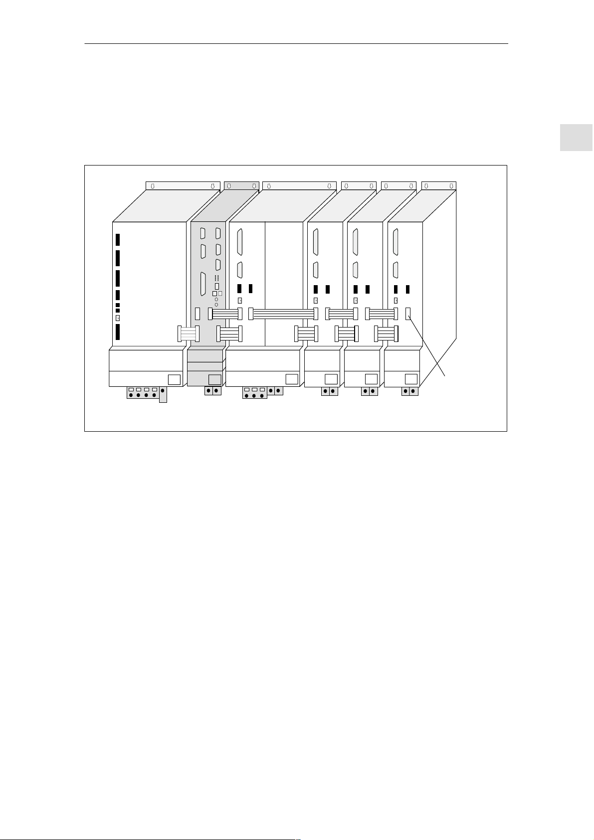
2.1.1 Overview
SIEMENS
03.96
Operator panel
Machine control panel
QWERTY keyboard
SIEMENS
SIMODRIVE
PS IM
SMs
SIMATIC STEP7–300 I/O devices
NCU terminal block
SIMODRIVE 611D
SINUMERIK 840D
MS (I/RF, OI)
Fig. 2-1 System overview of SINUMERIK 840 with SIMODRIVE 611 (diagrammatic)
2-20
NCU MSD
SINUMERIK 840D Installation and Start-Up Guide (IAD) – 04.00 Edition
FDD
Siemens AG 2000 All Rights Reserved

03.96
2.1.2 Mains infeed module
2 Configuration
2.1 Mechanical configuration
Mains infeed
module
Open-loopcontrolled infeed
OI
Infeed/regenerative
feedback module
I/RF
Arrangement of
mains infeed
module
The mains infeed module performs the following tasks:
S Supplies power for the SINUMERIK 840D and axis modules
S Generates the DC link voltage for the motors
S Regenerative feedback (I/RF) or braking resistor (OI) for generator-mode
operation
If the internal braking resistance is not sufficient, pulsed resistor modules can be
installed.
The I/RF module feeds back into excess DC link energy generated during braking the supply system.
The I/RF or OI module is installed as the first module on the left.
References: PJ1/ Planning Guide for SIMODRIVE 611D
2
Siemens AG 2000 All Rights Reserved
SINUMERIK 840D Installation and Start-Up Guide (IAD) – 04.00 Edition
2-21
2
2 Configuration
2.1 Mechanical configuration
2.1.3 NCU
X101
03.96
X102/
103
Operator panel interface
L2DP
Reserved
X112
X122
P–BUS/K–BUS interface
(PLC I/O devices)
PG–MPI interface
I/O device interface
+5 V
PR
PS
NF
PF
CF
PF0
CB
–
X121 X111
CP
RESETNMI
(cable distribution cabinet)
Various error and status LEDs
(H1/H2)
7-segment display (H3)
NMI button (S2)
S3
S4
RESET button (S1)
NCK start-up switch
PLC start-up switch
SIMODRIVE 611D interface
X130B
X130A
Digitizing module connection
Device bus interface
2-22
X172
MEMORY–CARD
PCMCIA slot
(X173)
Fig. 2-2 Interfaces, control and display elements of NCU module
SINUMERIK 840D Installation and Start-Up Guide (IAD) – 04.00 Edition
Siemens AG 2000 All Rights Reserved
03.96
2.2 Electrical configuration
2.1.4 General configuration of SINUMERIK 840D system
2 Configuration
2
SIEMENS
SIMODRIVE
NE (I/RF, UE)
Fig. 2-3 General configuration of SINUMERIK 840D
NCU MSD
2.2 Electrical configuration
2.2.1 Component connections
FDD
Bus terminating
connector
FDD FDD
Siemens AG 2000 All Rights Reserved
SINUMERIK 840D Installation and Start-Up Guide (IAD) – 04.00 Edition
2-23
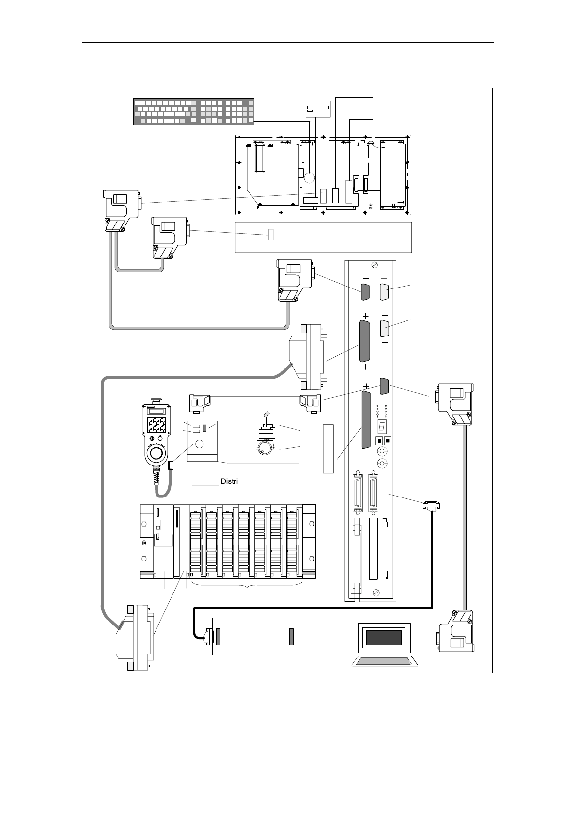
2 Configuration
2.2 Electrical configuration
03.96
2
QWERTY
1) X8/X9 on MMC 101/102 only
MPI bus cable
SIMATIC S7–300 IM connecting cable
ISA adapter
X20
Floppy
X9
MMC
X10
X4
1)
Cable for data
input/output V24
Parallel interface
1)
e.g. printer/streamer
Operator panel
X8
X6
(rear view)
Power supply
MCP
(rear view)
–X101
–X102
NCU
L2DP
Reserved
for servicing
–X111
–X112
–X122
HHU
MPI cable
X1
X2
X5
X4
X3
HHU handwheel
Distributor box
SIMATIC S7–300 I/O devices
X2
IM
PS SMs
IN OUT
X20 X21
NCU terminal block
Cable distribution
cabinet
to drive bus
–X121
X130B
–X172
MPI cable
or
MPI–PG cable
X130A
MEMORY–CARD
PG
Fig. 2-4 Connection configuration
2-24
SINUMERIK 840D Installation and Start-Up Guide (IAD) – 04.00 Edition
Siemens AG 2000 All Rights Reserved
03.96
2.2 Electrical configuration
Note
For cables and connectors, see
References: /PHD/, Configuring Manual 840D
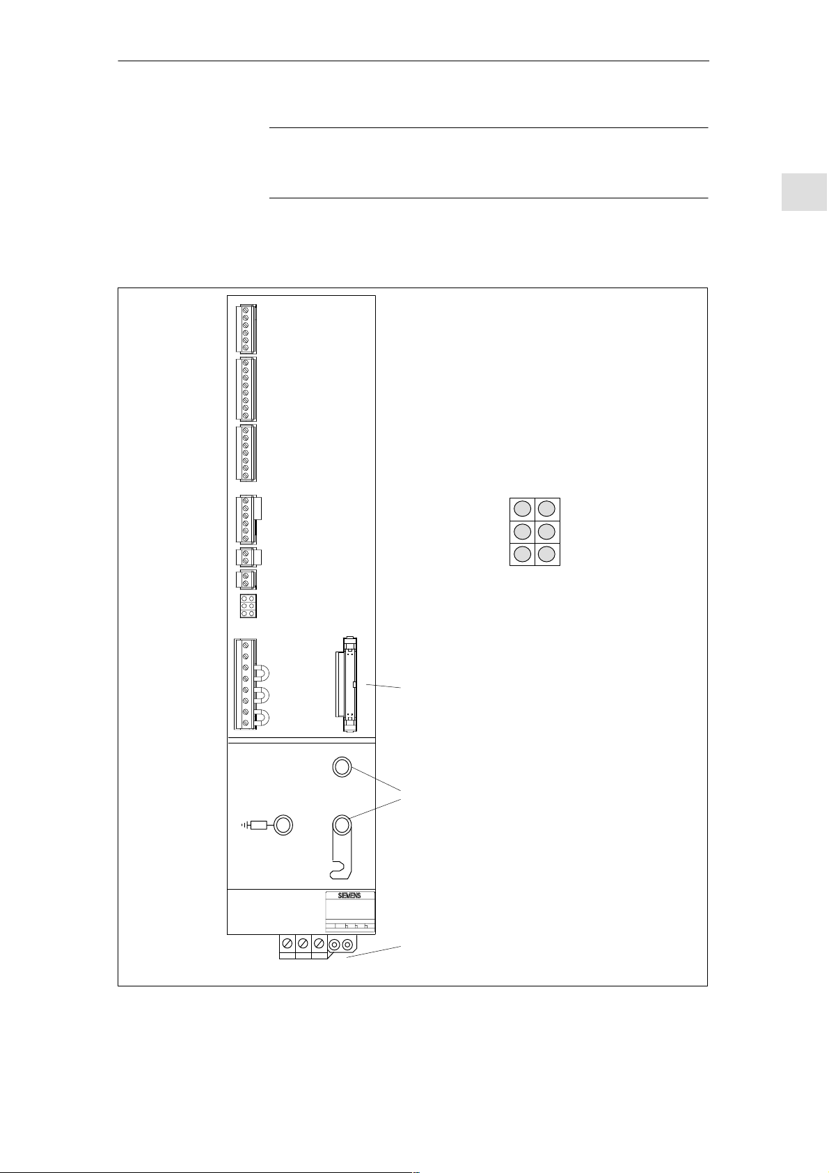
2.2.2 Connection of mains infeed module (OI, I/RF)
X111
X121
X141
2 Configuration
2
X161
X171
X172
LED
displays
X181
P600
M600
X351
Electronics power
supply faulty
Device is not ready,
no enable signal
(term. 63, 64 or 48)
Mains fault
Device bus
DC link connection
LED displays
Red
Green
Red
Red
Yellow
Red
5V voltage
level faulty
Device ready
(DC link
precharged)
DC link overvoltage
Power supply
U1 V1 W1 PE1
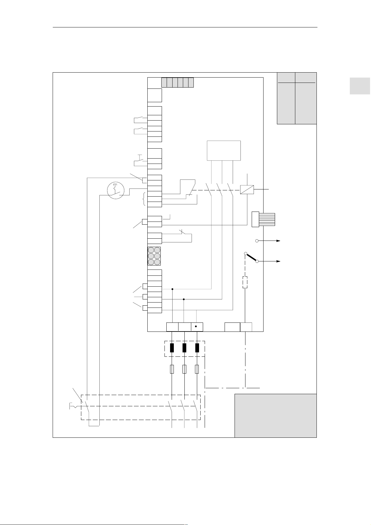
Fig. 2-5 Interfaces for OI and I/RF module 10–55KW
Siemens AG 2000 All Rights Reserved
SINUMERIK 840D Installation and Start-Up Guide (IAD) – 04.00 Edition
2-25
2
2 Configuration
2.2 Electrical configuration
03.96
Relay contact
for
Ready message
Relay contact for group message I
and motor overtemperature
Pulse enable
Enable voltage
Enable voltage
Reference potential for enable voltage
Enabling signal for internal mains
contactor
Signaling contact for starting lockout
(NC contact)
Drive enable signal
P24
P15
N15
N24
M
M
RESET (R+term.15)
Enable voltage
Setting-up mode
Contactor energization,
start
Signaling contact
from mains contactor
NC contact
NO contact
2
74
73.1
73.2
–X111
72
5.3
t
5.2
–X121
5.1
63
9
9
64
19
7
–X141
45
44
10
15
15
R
9
–X161
112
48
111
213
113
NS1
NS2
AS1
AS2
–X171
–X172
DC link power supply for mains buffering
M500
P500
External infeed for electronics power supply
2U1
1U1
External infeed for electronics power supply
2V1
1V1
External infeed for electronics power supply
2W1
1W1
Fig. 2-6 Connection terminals on SIMODRIVE 611 mains supply module 10–55 KW
2-26
SINUMERIK 840D Installation and Start-Up Guide (IAD) – 04.00 Edition
Siemens AG 2000 All Rights Reserved
LED displays
–X181
03.96
2 Configuration
2.2 Electrical configuration
Typical circuit
I/RF module
Pushbutton contact
1)
1)
1)
63
9
9
64
19
15
R
9
112
48
111
213
113
NS1
NS2
AS1
AS2
M500
P500
2U1
1U1
2V1
1V1
2W1
1W1
S1.6
S1.5
X111
X121
X141
X161
L+
X171
X172
LEDs
X181
S1.4
S1.3
S1.2
S1–DIP switch
S1.1
Mains supply module
Power section
L–
P600
M600
100 k
X351
S1 Default
S1.1
S1.2
S1.3
S1.4
S1.5
S1.6
*Do not alter
Internal mains
contactor
Device bus
P600
to the
axis modules
M600
off
off
off
off*
off
off*
2
W1V1U1
1U2 1V2 1W2
Commutating
reactor, on I/RF
module only
Mains fuses for
Leading
contact
Fig. 2-7 Example of three-conductor connection (standard circuit)
Siemens AG 2000 All Rights Reserved
SINUMERIK 840D Installation and Start-Up Guide (IAD) – 04.00 Edition
I/RF or OI
module
Master switch
Supply
1U1 1W11V1
L1 L2 L3
PE
X131
PE
1) Jumpers inserted in
delivery state
Important!
Terminal 48 must be de-energized 10 ms before the mains
contacts of the master switch
open (e.g. by means of leading
contact)
2-27
ÊÊ
ÊÊ
ÊÊ
2 Configuration
2.2 Electrical configuration
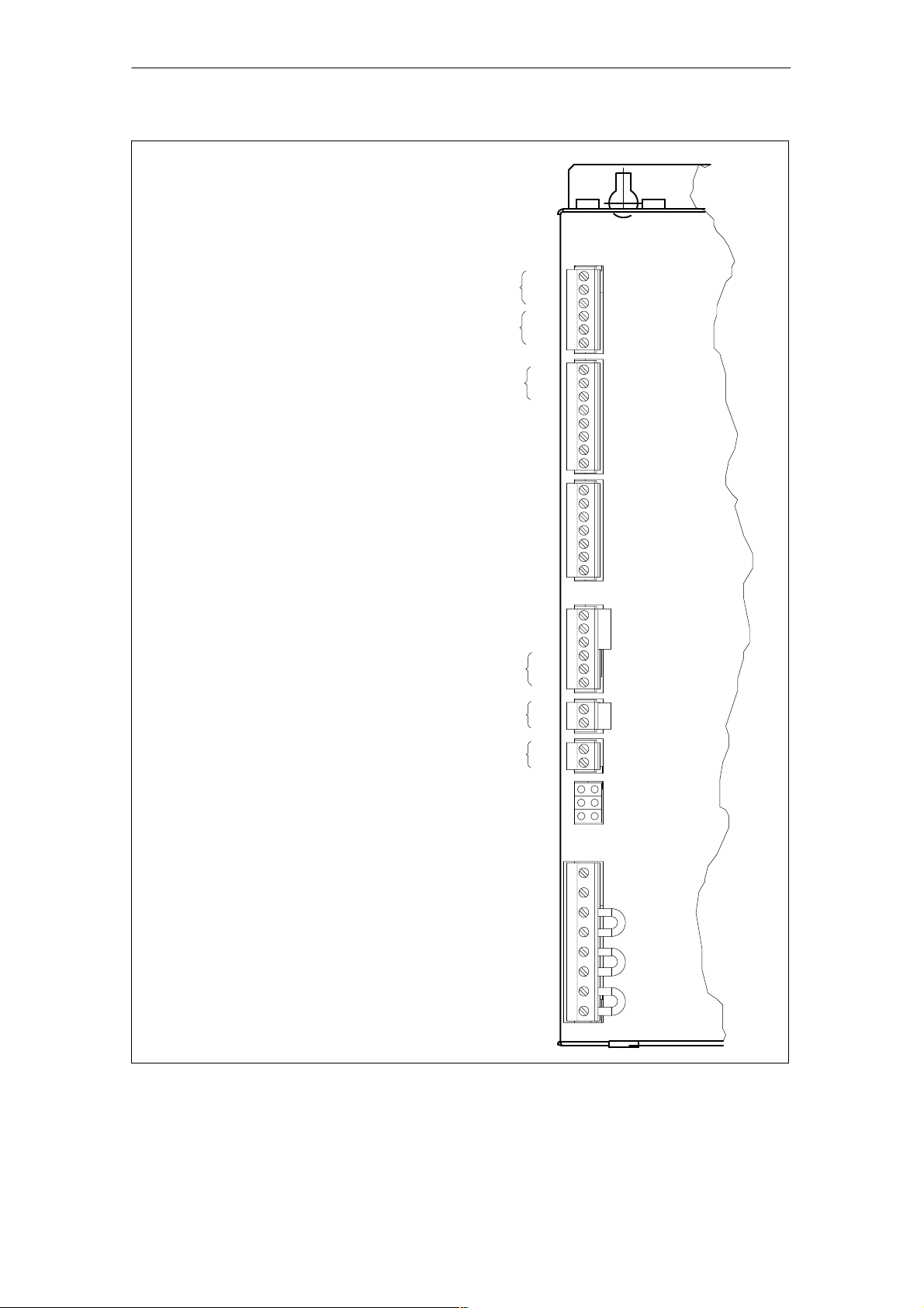
2.2.3 Motor connection
03.96
2
X411
Motor
encoder
Axis 1
X421
Direct position
Axis 1
X431
Relay terminals
Pulse enable
X141
Drive bus
X151
Device bus
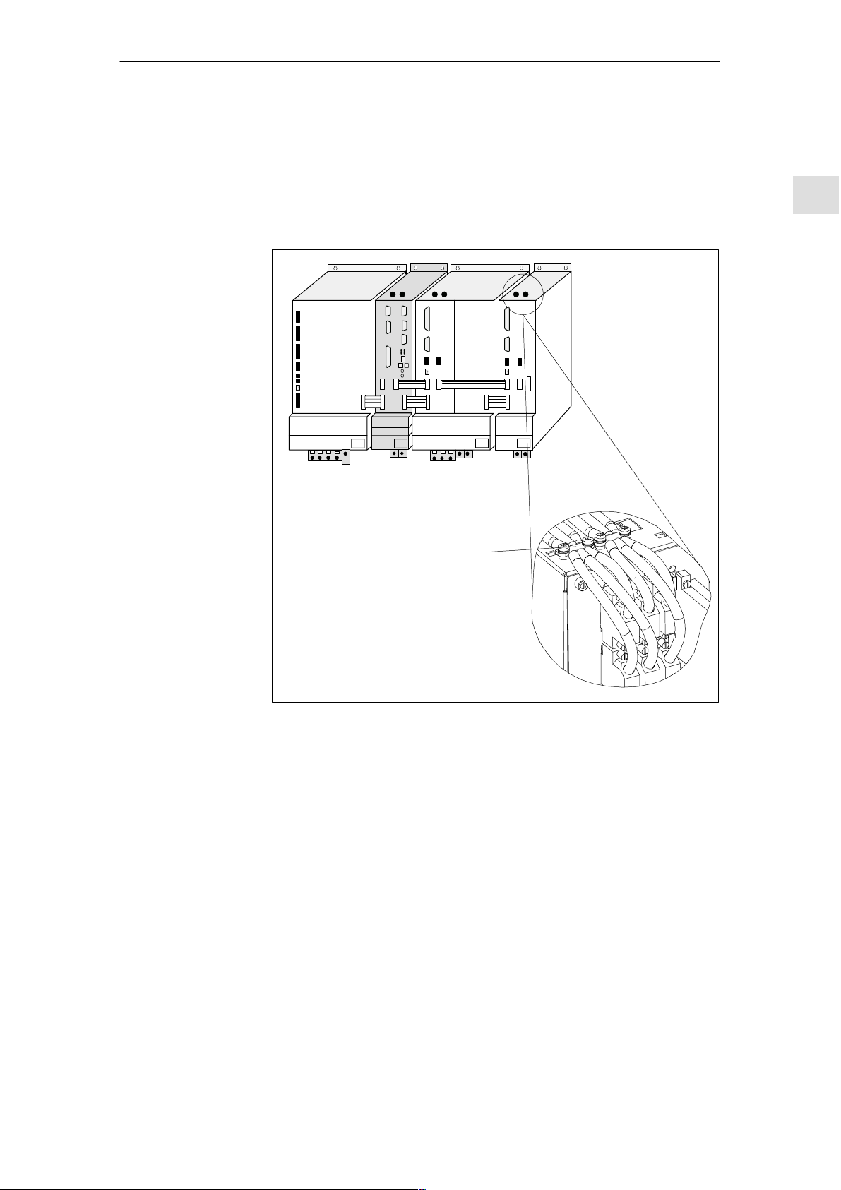
2-axis FDD module 1-axis FDD/MSD module
X35
X34
X412
Motor encoder
Axis 2
X422
Direct position
Axis 2
X432
BEROR
terminals
X341
X351
X411
Motor
encoder
X421
Direct position
X431
Relay terminals
Pulse enable
X141
Drive bus
X151
Device bus
X35
X34
X432
BEROR
terminals
X341
X351
P600
DC link
busbar
M600
PE terminals PE1 PE2
Fig. 2-8 Design of FDD/MSD modules
Rating plate
Motor
connecting
terminals
A1 and A2
DC link
busbar
Motor
connecting
terminals
P600
M600
Rating plate
X131
U2 V2 W2 PE1 PE2
2-28
SINUMERIK 840D Installation and Start-Up Guide (IAD) – 04.00 Edition
Siemens AG 2000 All Rights Reserved
03.96
2.2.4 Encoder connection
2 Configuration
2.2 Electrical configuration
Motor measuring
system and motor
connection
The motor measuring system of the connected motor must always be connected to connector X411 of the same module.
SIEMENS
SIMODRIVE
MS (I/RF, OI)
NCU MSD
Scheme for
shielding bus
FDD
2
Fig. 2-9 Connection of encoder cables
Siemens AG 2000 All Rights Reserved
SINUMERIK 840D Installation and Start-Up Guide (IAD) – 04.00 Edition
2-29
2 Configuration
2.2 Electrical configuration
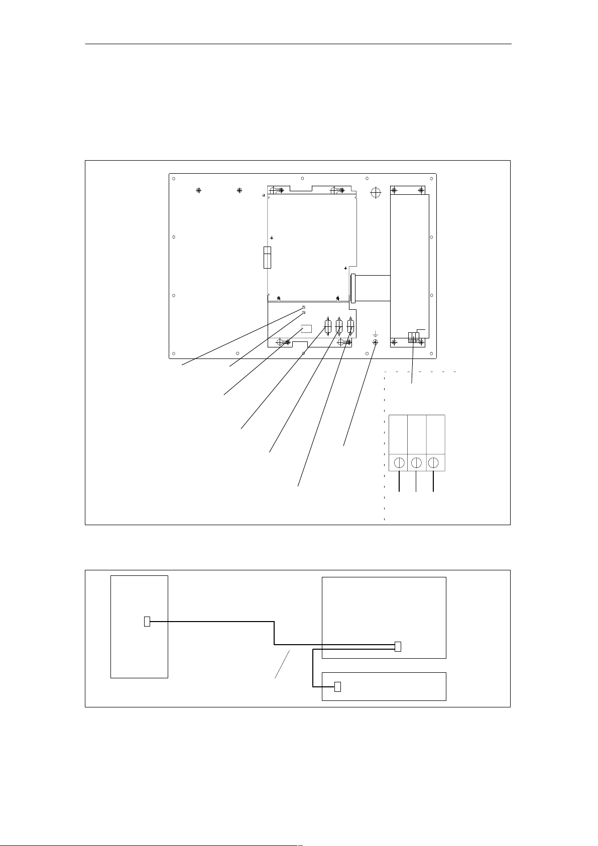
2.2.5 Connection of MMC100 and MMC102/103
03.96
2
MMC100
RESET
button
External keyboard interface
(the keyboard must be set
to the XT setting)
NMI
button
MMC 100
S1
S2
X10
Power supply
X3
X5 X4
X6
Chassis
Voltage
supply
RS 232 serial interface
VGA
interface
MPI interface for
connection of operator panel
Fig. 2-10 Rear of operator panel with MMC 100
X101
840D
6FX2 002–4EA04–1xx0 or
6FX2 002–4EA02–1xx0
Fig. 2-11 Connection of MMC100/102/103 to SINUMERIK 840D system
PE conductor
terminal
X20
24 V 0 V PE
MMC 100/102/103
X4
MCP
2-30
SINUMERIK 840D Installation and Start-Up Guide (IAD) – 04.00 Edition
Siemens AG 2000 All Rights Reserved
 Loading...