

Page 1

SINUMERIK
SINUMERIK 840D sl
Turning
Valid for:
SINUMERIK 840D sl / 840DE sl
Software version
CNC system software for 840D sl / 840DE sl V4.92
SINUMERIK Operate for PCU/PC V4.92
Preface
Fundamental safety
instructions
1
Operating Manual
Introduction
Multitouch operation with
SINUMERIK Operate
Setting up the machine
Working in manual mode
Machining the workpiece
Simulating machining
Creating a G code program
2
3
4
5
6
7
8
06/2019
A5E44903486B AB
Creating a ShopTurn program
Programming technology
functions (cycles)
Multi-channel machining
Collision avoidance
Tool management
Managing programs
Alarm, error and system
messages
Continued on next page
9
10
11
12
13
14
15
Page 2

Siemens AG
Digital Industries
Postfach 48 48
90026 NÜRNBERG
GERMANY
Document order number: A5E44903486B AB
Ⓟ 06/2019 Subject to change
Copyright © Siemens AG 2008 - 2019.
All rights reserved
Page 3

SINUMERIK 840D sl
Turning
Continued
Working with Manual
Machine
Working with a B axis (only
840D sl)
16
17
Operating Manual
Working with two tool carriers
Teaching in a program
HT 8 (840D sl only)
Ctrl-Energy
Easy Extend
Appendix
18
19
20
21
22
A
Page 4
Legal information
Warning notice system
This manual contains notices you have to observe in order to ensure your personal safety, as well as to prevent
damage to property. The notices referring to your personal safety are highlighted in the manual by a safety alert
symbol, notices referring only to property damage have no safety alert symbol. These notices shown below are
graded according to the degree of danger.
DANGER
indicates that death or severe personal injury will result if proper precautions are not taken.
WARNING
indicates that death or severe personal injury may result if proper precautions are not taken.
CAUTION
indicates that minor personal injury can result if proper precautions are not taken.
NOTICE
indicates that property damage can result if proper precautions are not taken.
If more than one degree of danger is present, the warning notice representing the highest degree of danger will be
used. A notice warning of injury to persons with a safety alert symbol may also include a warning relating to property
damage.
Qualified Personnel
The product/system described in this documentation may be operated only by personnel qualified for the specific
task in accordance with the relevant documentation, in particular its warning notices and safety instructions. Qualified
personnel are those who, based on their training and experience, are capable of identifying risks and avoiding
potential hazards when working with these products/systems.
Proper use of Siemens products
Note the following:
WARNING
Siemens products may only be used for the applications described in the catalog and in the relevant technical
documentation. If products and components from other manufacturers are used, these must be recommended or
approved by Siemens. Proper transport, storage, installation, assembly, commissioning, operation and
maintenance are required to ensure that the products operate safely and without any problems. The permissible
ambient conditions must be complied with. The information in the relevant documentation must be observed.
Trademarks
All names identified by ® are registered trademarks of Siemens AG. The remaining trademarks in this publication
may be trademarks whose use by third parties for their own purposes could violate the rights of the owner.
Disclaimer of Liability
We have reviewed the contents of this publication to ensure consistency with the hardware and software described.
Since variance cannot be precluded entirely, we cannot guarantee full consistency. However, the information in this
publication is reviewed regularly and any necessary corrections are included in subsequent editions.
Siemens AG
Digital Industries
Postfach 48 48
90026 NÜRNBERG
GERMANY
Document order number: A5E44903486B AB
Ⓟ 06/2019 Subject to change
Copyright © Siemens AG 2008 - 2019.
All rights reserved
Page 5

Preface
SINUMERIK documentation
The SINUMERIK documentation is organized into the following categories:
● General documentation/catalogs
● User documentation
● Manufacturer/service documentation
Additional information
You can find information on the following topics at the following address (
support.industry.siemens.com/cs/de/en/view/108464614):
● Ordering documentation/overview of documentation
● Additional links to download documents
● Using documentation online (find and search in manuals/information)
If you have any questions regarding the technical documentation (e.g. suggestions,
corrections), please send an e-mail to the following address
(mailto:[email protected]).
mySupport/Documentation
At the following address (https://support.industry.siemens.com/My/ww/en/documentation),
you can find information on how to create your own individual documentation based on
Siemens' content, and adapt it for your own machine documentation.
Training
At the following address (http://www.siemens.com/sitrain), you can find information about
SITRAIN (Siemens training on products, systems and solutions for automation and drives).
FAQs
https://
You can find Frequently Asked Questions in the Service&Support pages under Product
Support (https://support.industry.siemens.com/cs/de/en/ps/faq).
SINUMERIK
You can find information about SINUMERIK at the following address (http://www.siemens.com/
sinumerik).
Turning
Operating Manual, 06/2019, A5E44903486B AB 5
Page 6

Preface
Target group
Benefits
Standard scope
This documentation is intended for users of turning machines running the SINUMERIK Operate
software.
The operating manual helps users familiarize themselves with the control elements and
commands. Guided by the manual, users are capable of responding to problems and taking
corrective action.
This documentation describes the functionality of the standard scope. Extensions or changes
made by the machine manufacturer are documented by the machine manufacturer.
Other functions not described in this documentation might be executable in the control.
However, no claim can be made regarding the availability of these functions when the
equipment is first supplied or in the event of servicing.
Furthermore, for the sake of clarity, this documentation does not contain all detailed information
about all types of the product and cannot cover every conceivable case of installation, operation
or maintenance.
Terms
The meanings of some basic terms used in this documentation are given below.
Program
A program is a sequence of instructions to the CNC which combine to produce a specific
workpiece on the machine.
Contour
The term contour refers generally to the outline of a workpiece. More specifically, it refers to the
section of the program that defines the outline of a workpiece comprising individual elements.
Cycle
A cycle, such as the tapping cycle, is a subprogram defined in SINUMERIK Operate for
executing a frequently repeated machining operation.
Note regarding the General Data Protection Regulation
Siemens observes standard data protection principles, in particular the principle of privacy by
design. That means that
this product does not process / store any personal data, only technical functional data (e.g. time
stamps). If a user links this data with other data (e.g. a shift schedule) or stores personal data
on the same storage medium (e.g. hard drive) and thus establishes a link to a person or
persons, then the user is responsible for ensuring compliance with the relevant data protection
regulations.
Turning
6 Operating Manual, 06/2019, A5E44903486B AB
Page 7

Technical Support
Preface
Country-specific telephone numbers for technical support are provided in the Internet at the
following address (
https://support.industry.siemens.com/sc/ww/en/sc/2090) in the "Contact"
area.
Turning
Operating Manual, 06/2019, A5E44903486B AB 7
Page 8

Preface
Turning
8 Operating Manual, 06/2019, A5E44903486B AB
Page 9

Table of contents
Preface .........................................................................................................................................................5
1 Fundamental safety instructions.................................................................................................................23
1.1 General safety instructions.....................................................................................................23
1.2 Warranty and liability for application examples ......................................................................24
1.3 Industrial security ...................................................................................................................25
2 Introduction.................................................................................................................................................27
2.1 Product overview....................................................................................................................27
2.2 Operator panel fronts .............................................................................................................28
2.2.1 Overview ................................................................................................................................28
2.2.2 Keys of the operator panel .....................................................................................................30
2.3 Machine control panels ..........................................................................................................38
2.3.1 Overview ................................................................................................................................38
2.3.2 Controls on the machine control panel...................................................................................38
2.4 User interface.........................................................................................................................42
2.4.1 Screen layout .........................................................................................................................42
2.4.2 Status display.........................................................................................................................43
2.4.3 Actual value window...............................................................................................................45
2.4.4 T,F,S window .........................................................................................................................47
2.4.5 Current block display..............................................................................................................48
2.4.6 Operation via softkeys and buttons........................................................................................50
2.4.7 Entering or selecting parameters ...........................................................................................51
2.4.8 Pocket calculator....................................................................................................................53
2.4.9 Pocket calculator functions ....................................................................................................54
2.4.10 Context menu.........................................................................................................................56
2.4.11 Changing the user interface language ...................................................................................57
2.4.12 Entering Chinese characters..................................................................................................57
2.4.12.1 Function - input editor ............................................................................................................57
2.4.12.2 Entering Asian characters ......................................................................................................59
2.4.12.3 Editing the dictionary..............................................................................................................60
2.4.13 Entering Korean characters ...................................................................................................62
2.4.14 Protection levels.....................................................................................................................64
2.4.15 Cleaning mode .......................................................................................................................66
2.4.16 Display live image from a camera ..........................................................................................66
2.4.17 Online help in SINUMERIK Operate ......................................................................................67
3 Multitouch operation with SINUMERIK Operate.........................................................................................71
3.1 Multitouch panels ...................................................................................................................71
3.2 Touch-sensitive user interface ...............................................................................................72
3.3 Finger gestures ......................................................................................................................73
3.4 Multitouch user interface ........................................................................................................76
Turning
Operating Manual, 06/2019, A5E44903486B AB 9
Page 10

Table of contents
3.4.1 Screen layout .........................................................................................................................76
3.4.2 Function key block .................................................................................................................76
3.4.3 Further operator touch controls..............................................................................................77
3.4.4 Virtual keyboard .....................................................................................................................78
3.4.5 Special "tilde" character .........................................................................................................78
3.5 Expansion with side screen....................................................................................................79
3.5.1 Overview ................................................................................................................................79
3.5.2 Sidescreen with standard windows ........................................................................................79
3.5.3 Standard widgets ...................................................................................................................81
3.5.4 "Actual value" widget..............................................................................................................81
3.5.5 "Zero point" widget .................................................................................................................82
3.5.6 "Alarms" widget ......................................................................................................................82
3.5.7 "NC/PLC variables" widget.....................................................................................................82
3.5.8 "Axle load" widget ..................................................................................................................83
3.5.9 "Tool" widget ..........................................................................................................................83
3.5.10 "Service life" widget................................................................................................................84
3.5.11 "Program runtime" widget ......................................................................................................84
3.5.12 Widget "Camera 1" and "Camera 2" ......................................................................................84
3.5.13 Sidescreen with pages for the ABC keyboard and/or machine control panel ........................85
3.5.14 Example 1: ABC keyboard in the sidescreen.........................................................................86
3.5.15 Example 2: Machine control panel in the sidescreen.............................................................87
3.6 SINUMERIK Operate Display Manager (840D sl only) ..........................................................88
3.6.1 Overview ................................................................................................................................88
3.6.2 Screen layout .........................................................................................................................89
3.6.3 Operator controls ...................................................................................................................89
4 Setting up the machine...............................................................................................................................93
4.1 Switching on and switching off ...............................................................................................93
4.2 Approaching a reference point ...............................................................................................94
4.2.1 Referencing axes ...................................................................................................................94
4.2.2 User agreement .....................................................................................................................95
4.3 Modes and mode groups .......................................................................................................97
4.3.1 General ..................................................................................................................................97
4.3.2 Modes groups and channels ..................................................................................................99
4.3.3 Channel switchover................................................................................................................99
4.4 Settings for the machine ......................................................................................................101
4.4.1 Switching over the coordinate system (MCS/WCS).............................................................101
4.4.2 Switching the unit of measurement ......................................................................................101
4.4.3 Setting the zero offset ..........................................................................................................103
4.5 Measuring the tool................................................................................................................105
4.5.1 Measuring a tool manually ...................................................................................................105
4.5.2 Measuring a tool with a tool probe .......................................................................................107
4.5.3 Calibrating the tool probe .....................................................................................................109
4.5.4 Measuring a tool with a magnifying glass ............................................................................110
4.5.5 Logging tool measurement results .......................................................................................111
4.6 Measuring the workpiece zero .............................................................................................112
4.6.1 Measuring the workpiece zero .............................................................................................112
4.6.2 Logging measurement results for the workpiece zero .........................................................113
Turning
10 Operating Manual, 06/2019, A5E44903486B AB
Page 11

Table of contents
4.7 Settings for the measurement result log ..............................................................................115
4.8 Zero offsets ..........................................................................................................................117
4.8.1 Display active zero offset .....................................................................................................118
4.8.2 Displaying the zero offset "overview" ...................................................................................118
4.8.3 Displaying and editing base zero offset ...............................................................................119
4.8.4 Displaying and editing settable zero offset...........................................................................120
4.8.5 Displaying and editing details of the zero offsets .................................................................121
4.8.6 Deleting a zero offset ...........................................................................................................123
4.8.7 Measuring the workpiece zero .............................................................................................123
4.9 Monitoring axis and spindle data..........................................................................................125
4.9.1 Specify working area limitations...........................................................................................125
4.9.2 Editing spindle data..............................................................................................................125
4.9.3 Spindle chuck data...............................................................................................................126
4.10 Displaying setting data lists..................................................................................................130
4.11 Handwheel assignment........................................................................................................131
4.12 MDA .....................................................................................................................................133
4.12.1 Loading an MDA program from the Program Manager........................................................133
4.12.2 Saving an MDA program......................................................................................................134
4.12.3 Editing/executing a MDI program.........................................................................................135
4.12.4 Deleting an MDA program....................................................................................................136
5 Working in manual mode..........................................................................................................................137
5.1 General ................................................................................................................................137
5.2 Selecting a tool and spindle .................................................................................................138
5.2.1 T,S,M window.......................................................................................................................138
5.2.2 Selecting a tool.....................................................................................................................139
5.2.3 Starting and stopping the spindle manually .........................................................................140
5.2.4 Positioning the spindle .........................................................................................................141
5.3 Traversing axes....................................................................................................................142
5.3.1 Traverse axes by a defined increment .................................................................................142
5.3.2 Traversing axes by a variable increment .............................................................................143
5.4 Positioning axes ...................................................................................................................144
5.5 Manual retraction .................................................................................................................145
5.6 Simple stock removal of workpiece......................................................................................147
5.7 Thread synchronizing...........................................................................................................150
5.8 Default settings for manual mode ........................................................................................152
6 Machining the workpiece ..........................................................................................................................153
6.1 Starting and stopping machining..........................................................................................153
6.2 Selecting a program .............................................................................................................155
6.3 Executing a trail program run ...............................................................................................156
6.4 Displaying the current program block...................................................................................158
6.4.1 Current block display............................................................................................................158
6.4.2 Displaying a basic block ......................................................................................................159
Turning
Operating Manual, 06/2019, A5E44903486B AB 11
Page 12

Table of contents
6.4.3 Display program level...........................................................................................................160
6.5 Correcting a program ...........................................................................................................162
6.6 Repositioning axes...............................................................................................................163
6.7 Starting machining at a specific point...................................................................................164
6.7.1 Use block search..................................................................................................................164
6.7.2 Continuing program from search target ...............................................................................166
6.7.3 Simple search target definition.............................................................................................166
6.7.4 Defining an interruption point as search target ....................................................................167
6.7.5 Entering the search target via search pointer ......................................................................167
6.7.6 Parameters for block search in the search pointer...............................................................168
6.7.7 Block search mode...............................................................................................................169
6.7.8 Block search for position pattern..........................................................................................171
6.8 Controlling the program run .................................................................................................173
6.8.1 Program control....................................................................................................................173
6.8.2 Skip blocks ...........................................................................................................................174
6.9 Overstore .............................................................................................................................176
6.10 Editing a program.................................................................................................................178
6.10.1 Searching in programs .........................................................................................................178
6.10.2 Replacing program text ........................................................................................................180
6.10.3 Copying/pasting/deleting a program block ...........................................................................181
6.10.4 Renumbering a program ......................................................................................................183
6.10.5 Creating a program block.....................................................................................................184
6.10.6 Opening additional programs ...............................................................................................185
6.10.7 Editor settings ......................................................................................................................186
6.11 Working with DXF files .........................................................................................................190
6.11.1 Overview ..............................................................................................................................190
6.11.2 Displaying CAD drawings.....................................................................................................191
6.11.2.1 Open a DXF file....................................................................................................................191
6.11.2.2 Cleaning a DXF file ..............................................................................................................191
6.11.2.3 Enlarging or reducing the CAD drawing...............................................................................192
6.11.2.4 Changing the section ...........................................................................................................193
6.11.2.5 Rotating the view..................................................................................................................193
6.11.2.6 Displaying/editing information for the geometric data ..........................................................194
6.11.3 Importing and editing a DXF file in the editor .......................................................................195
6.11.3.1 General procedure ...............................................................................................................195
6.11.3.2 Specifying a reference point.................................................................................................195
6.11.3.3 Assigning the machining plane ............................................................................................196
6.11.3.4 Setting the tolerance ............................................................................................................196
6.11.3.5 Selecting the machining range / deleting the range and element ........................................197
6.11.3.6 Saving the DXF file ..............................................................................................................198
6.11.3.7 Transferring the drilling positions .........................................................................................199
6.11.3.8 Accepting contours...............................................................................................................201
6.12 Display and edit user variables ............................................................................................204
6.12.1 Overview ..............................................................................................................................204
6.12.2 Global R parameters ............................................................................................................205
6.12.3 R parameters .......................................................................................................................206
6.12.4 Displaying global user data (GUD).......................................................................................208
6.12.5 Displaying channel GUDs ....................................................................................................209
Turning
12 Operating Manual, 06/2019, A5E44903486B AB
Page 13

Table of contents
6.12.6 Displaying local user data (LUD)..........................................................................................210
6.12.7 Displaying program user data (PUD) ...................................................................................211
6.12.8 Searching for user variables ................................................................................................211
6.13 Displaying G functions and auxiliary functions.....................................................................214
6.13.1 Selected G functions ............................................................................................................214
6.13.2 All G functions ......................................................................................................................216
6.13.3 G functions for mold making ................................................................................................216
6.13.4 Auxiliary functions ................................................................................................................217
6.14 Displaying superimpositions.................................................................................................219
6.15 Mold making view.................................................................................................................222
6.15.1 Starting the mold making view .............................................................................................224
6.15.2 Adapting the mold making view ...........................................................................................224
6.15.3 Specifically jump to the program block.................................................................................225
6.15.4 Searching for program blocks ..............................................................................................226
6.15.5 Changing the view................................................................................................................227
6.15.5.1 Enlarging or reducing the graphical representation .............................................................227
6.15.5.2 Moving and rotating the graphic...........................................................................................228
6.15.5.3 Modifying the viewport .........................................................................................................228
6.16 Displaying the program runtime and counting workpieces...................................................230
6.17 Setting for automatic mode ..................................................................................................232
7 Simulating machining ...............................................................................................................................235
7.1 Overview ..............................................................................................................................235
7.2 Simulation before machining of the workpiece.....................................................................241
7.3 Simultaneous recording before machining of the workpiece................................................243
7.4 Simultaneous recording during machining of the workpiece................................................244
7.5 Different views of the workpiece ..........................................................................................245
7.5.1 Side view..............................................................................................................................245
7.5.2 Half section ..........................................................................................................................246
7.5.3 Face view .............................................................................................................................246
7.5.4 3D view ................................................................................................................................246
7.5.5 2-window ..............................................................................................................................247
7.6 Graphical display..................................................................................................................248
7.7 Editing the simulation display...............................................................................................249
7.7.1 Blank display ........................................................................................................................249
7.7.2 Showing and hiding the tool path ........................................................................................250
7.8 Program control during the simulation .................................................................................252
7.8.1 Changing the feedrate .........................................................................................................252
7.8.2 Simulating the program block by block ................................................................................253
7.9 Editing and adapting a simulation graphic ..........................................................................254
7.9.1 Enlarging or reducing the graphical representation .............................................................254
7.9.2 Panning a graphical representation .....................................................................................255
7.9.3 Rotating the graphical representation ..................................................................................255
7.9.4 Modifying the viewport .........................................................................................................256
7.9.5 Defining cutting planes.........................................................................................................256
Turning
Operating Manual, 06/2019, A5E44903486B AB 13
Page 14

Table of contents
7.10 Displaying simulation alarms................................................................................................258
8 Creating a G code program ......................................................................................................................259
8.1 Graphical programming........................................................................................................259
8.2 Program views .....................................................................................................................260
8.3 Program structure ................................................................................................................265
8.4 Fundamentals ......................................................................................................................266
8.4.1 Machining planes .................................................................................................................266
8.4.2 Current planes in cycles and input screens .........................................................................266
8.4.3 Programming a tool (T) ........................................................................................................267
8.5 Generating a G code program .............................................................................................268
8.6 Blank input ...........................................................................................................................269
8.7 Machining plane, milling direction, retraction plane, safe clearance and feedrate (PL, RP,
SC, F)...................................................................................................................................272
8.8 Selection of the cycles via softkey .......................................................................................273
8.9 Calling technology cycles.....................................................................................................277
8.9.1 Hiding cycle parameters.......................................................................................................277
8.9.2 Setting data for cycles..........................................................................................................277
8.9.3 Checking cycle parameters..................................................................................................277
8.9.4 Programming variables ........................................................................................................278
8.9.5 Changing a cycle call ...........................................................................................................278
8.9.6 Compatibility for cycle support ............................................................................................279
8.9.7 Additional functions in the input screens..............................................................................279
8.10 Measuring cycle support ......................................................................................................281
9 Creating a ShopTurn program..................................................................................................................283
9.1 Graphic program control, ShopTurn programs ....................................................................283
9.2 Program views .....................................................................................................................284
9.3 Program structure ................................................................................................................290
9.4 Fundamentals ......................................................................................................................291
9.4.1 Machining planes .................................................................................................................291
9.4.2 Machining cycle, approach/retraction...................................................................................292
9.4.3 Absolute and incremental dimensions .................................................................................294
9.4.4 Polar coordinates .................................................................................................................296
9.4.5 Clamping the spindle............................................................................................................296
9.5 Creating a ShopTurn program .............................................................................................298
9.6 Program header ...................................................................................................................300
9.7 Generating program blocks..................................................................................................303
9.8 Tool, offset value, feedrate and spindle speed (T, D, F, S, V) .............................................304
9.9 Call work offsets...................................................................................................................307
9.10 Repeating program blocks ...................................................................................................308
9.11 Entering the number of workpieces......................................................................................310
Turning
14 Operating Manual, 06/2019, A5E44903486B AB
Page 15

Table of contents
9.12 Changing program blocks ....................................................................................................311
9.13 Changing program settings ..................................................................................................312
9.14 Selection of the cycles via softkey .......................................................................................314
9.15 Calling technology functions ................................................................................................319
9.15.1 Additional functions in the input screens..............................................................................319
9.15.2 Checking cycle parameters..................................................................................................319
9.15.3 Setting data for technological functions ...............................................................................319
9.15.4 Programming variables ........................................................................................................320
9.15.5 Changing a cycle call ...........................................................................................................320
9.15.6 Compatibility for cycle support ............................................................................................321
9.16 Programming the approach/retraction cycle ........................................................................322
9.17 Programming retraction to tool change point .......................................................................324
9.18 Measuring cycle support ......................................................................................................325
9.19 Example: Standard machining .............................................................................................326
9.19.1 Workpiece drawing...............................................................................................................327
9.19.2 Programming........................................................................................................................327
9.19.3 Results/simulation test .........................................................................................................339
9.19.4 G code machining program..................................................................................................341
10 Programming technology functions (cycles).............................................................................................345
10.1 Drilling ..................................................................................................................................345
10.1.1 General ................................................................................................................................345
10.1.2 Centering (CYCLE81) ..........................................................................................................346
10.1.3 Drilling (CYCLE82)...............................................................................................................348
10.1.4 Reaming (CYCLE85) ...........................................................................................................352
10.1.5 Boring (CYCLE86) ...............................................................................................................355
10.1.6 Deep-hole drilling 1 (CYCLE83)...........................................................................................357
10.1.7 Deep-hole drilling 2 (CYCLE830).........................................................................................363
10.1.8 Tapping (CYCLE84, 840).....................................................................................................373
10.1.9 Drill and thread milling (CYCLE78) ......................................................................................381
10.1.10 Positions and position patterns ............................................................................................384
10.1.11 Arbitrary positions (CYCLE802) ...........................................................................................386
10.1.12 Row position pattern (HOLES1) ...........................................................................................390
10.1.13 Grid or frame position pattern (CYCLE801) ........................................................................393
10.1.14 Circle or pitch circle position pattern (HOLES2)...................................................................397
10.1.15 Displaying and hiding positions ............................................................................................403
10.1.16 Repeating positions..............................................................................................................404
10.2 Rotate...................................................................................................................................406
10.2.1 General ................................................................................................................................406
10.2.2 Stock removal (CYCLE951) .................................................................................................406
10.2.3 Groove (CYCLE930) ............................................................................................................409
10.2.4 Undercut form E and F (CYCLE940) ...................................................................................412
10.2.5 Thread undercuts (CYCLE940)............................................................................................414
10.2.6 Thread turning (CYCLE99) ..................................................................................................417
10.2.7 Thread chain (CYCLE98).....................................................................................................434
10.2.8 Cut-off (CYCLE92) ...............................................................................................................440
10.3 Contour turning ....................................................................................................................442
Turning
Operating Manual, 06/2019, A5E44903486B AB 15
Page 16

Table of contents
10.3.1 General information..............................................................................................................442
10.3.2 Representation of the contour..............................................................................................443
10.3.3 Creating a new contour ........................................................................................................444
10.3.4 Creating contour elements ...................................................................................................446
10.3.5 Entering the master dimension ............................................................................................452
10.3.6 Changing the contour...........................................................................................................453
10.3.7 Contour call (CYCLE62) - only for G code program.............................................................454
10.3.8 Stock removal (CYCLE952) .................................................................................................455
10.3.9 Stock removal rest (CYCLE952) ..........................................................................................465
10.3.10 Plunge-cutting (CYCLE952) .................................................................................................467
10.3.11 Plunge-cutting rest (CYCLE952) ..........................................................................................473
10.3.12 Plunge-turning (CYCLE952) ................................................................................................476
10.3.13 Plunge-turning rest (CYCLE952) .........................................................................................482
10.4 Milling ...................................................................................................................................485
10.4.1 Face milling (CYCLE61).......................................................................................................485
10.4.2 Rectangular pocket (POCKET3) ..........................................................................................488
10.4.3 Circular pocket (POCKET4) .................................................................................................498
10.4.4 Rectangular spigot (CYCLE76)............................................................................................507
10.4.5 Circular spigot (CYCLE77)...................................................................................................513
10.4.6 Multi-edge (CYCLE79) .........................................................................................................519
10.4.7 Longitudinal groove (SLOT1) ...............................................................................................524
10.4.8 Circumferential groove (SLOT2) ..........................................................................................533
10.4.9 Open groove (CYCLE899) ...................................................................................................541
10.4.10 Long hole (LONGHOLE) - only for G code program ............................................................551
10.4.11 Thread milling (CYCLE70) ...................................................................................................553
10.4.12 Engraving (CYCLE60)..........................................................................................................557
10.5 Contour milling .....................................................................................................................564
10.5.1 General information..............................................................................................................564
10.5.2 Representation of the contour..............................................................................................564
10.5.3 Creating a new contour ........................................................................................................565
10.5.4 Creating contour elements ...................................................................................................568
10.5.5 Changing the contour...........................................................................................................573
10.5.6 Contour call (CYCLE62) - only for G code program.............................................................574
10.5.7 Path milling (CYCLE72) .......................................................................................................575
10.5.8 Contour pocket/contour spigot (CYCLE63/64).....................................................................581
10.5.9 Predrilling contour pocket (CYCLE64) .................................................................................583
10.5.10 Milling contour pocket (CYCLE63) .......................................................................................587
10.5.11 Contour pocket residual material (CYCLE63, option) ..........................................................593
10.5.12 Milling contour spigot (CYCLE63) ........................................................................................596
10.5.13 Contour spigot residual material (CYCLE63, option) ...........................................................601
10.6 Further cycles and functions ................................................................................................605
10.6.1 Swiveling plane / aligning tool (CYCLE800).........................................................................605
10.6.2 Swiveling tool (CYCLE800)..................................................................................................612
10.6.2.1 Aligning turning tools - only for G code program (CYCLE800) ............................................612
10.6.2.2 Aligning milling tools - only for G code program (CYCLE800) .............................................615
10.6.2.3 Preloading milling tools - only for G code program (CYCLE800).........................................615
10.6.3 High-speed settings (CYCLE832) ........................................................................................617
10.6.3.1 Parameters...........................................................................................................................620
10.6.4 Subroutines ..........................................................................................................................621
10.6.5 Adapt to load (CYCLE782)...................................................................................................623
Turning
16 Operating Manual, 06/2019, A5E44903486B AB
Page 17

Table of contents
10.7 Additional cycles and functions in ShopTurn .......................................................................625
10.7.1 Drilling centric.......................................................................................................................625
10.7.2 Thread centered...................................................................................................................628
10.7.3 Transformations ...................................................................................................................631
10.7.4 Translation ...........................................................................................................................633
10.7.5 Rotation................................................................................................................................634
10.7.6 Scaling .................................................................................................................................635
10.7.7 Mirroring ...............................................................................................................................635
10.7.8 Rotation C ............................................................................................................................636
10.7.9 Straight and circular machining............................................................................................637
10.7.10 Selecting a tool and machining plane ..................................................................................638
10.7.11 Programming a straight line .................................................................................................639
10.7.12 Programming a circle with known center point.....................................................................641
10.7.13 Programming a circle with known radius..............................................................................643
10.7.14 Polar coordinates .................................................................................................................645
10.7.15 Straight line polar .................................................................................................................646
10.7.16 Circle polar ...........................................................................................................................648
10.7.17 Machining with movable counterspindle ..............................................................................649
10.7.17.1 Programming example: Machining main spindle – Transfer workpiece – Machining
counterspindle......................................................................................................................650
10.7.17.2 Programming example: Machining counter-spindle – Transfer workpiece – Machining
main spindle .........................................................................................................................651
10.7.17.3 Programming example: Machining, counterspindle - without previous transfer...................651
10.7.17.4 Programming example: Machining bar material...................................................................652
10.7.18 Machining with fixed counterspindle ....................................................................................657
11 Multi-channel machining...........................................................................................................................661
11.1 Multi-channel view................................................................................................................661
11.1.1 Multi-channel view in the "Machine" operating area ............................................................661
11.1.2 Multi-channel view for large operator panels .......................................................................663
11.1.3 Setting the multi-channel view .............................................................................................665
11.2 Multi-channel support...........................................................................................................667
11.2.1 Working with several channels.............................................................................................667
11.2.2 Creating a multi-channel program........................................................................................668
11.2.3 Entering multi-channel data .................................................................................................668
11.2.4 Multi-channel functionality for large operator panels............................................................672
11.2.5 Editing the multi-channel program .......................................................................................674
11.2.5.1 Changing the job list.............................................................................................................674
11.2.5.2 Editing a G code multi-channel program..............................................................................675
11.2.5.3 Editing a ShopTurn multi-channel program..........................................................................677
11.2.5.4 Creating a program block.....................................................................................................684
11.2.6 Setting the multi-channel function ........................................................................................686
11.2.7 Synchronizing programs ......................................................................................................687
11.2.8 Insert WAIT marks ...............................................................................................................690
11.2.9 Optimizing the machining time .............................................................................................691
11.2.10 Automatic block building ......................................................................................................693
11.2.10.1 Creating automated program blocks ....................................................................................693
11.2.10.2 Editing a converted program ................................................................................................695
11.2.11 Simulating machining ...........................................................................................................696
11.2.11.1 Simulation ............................................................................................................................696
11.2.11.2 Different workpiece views for multi-channel support............................................................697
Turning
Operating Manual, 06/2019, A5E44903486B AB 17
Page 18

Table of contents
11.2.12 Display/edit the multi-channel functionality in the "Machine" operating area .......................698
11.2.12.1 Running-in a program ..........................................................................................................698
11.2.12.2 Block search and program control .......................................................................................699
11.2.13 Stock removal with 2 synchronized channels ......................................................................700
11.2.13.1 Job list ..................................................................................................................................702
11.2.13.2 Stock removal ......................................................................................................................704
11.2.14 Synchronizing a counterspindle ..........................................................................................705
12 Collision avoidance...................................................................................................................................711
12.1 Activating collision avoidance ..............................................................................................713
12.2 Set collision avoidance.........................................................................................................714
13 Tool management.....................................................................................................................................717
13.1 Lists for the tool management..............................................................................................717
13.2 Magazine management........................................................................................................719
13.3 Tool types.............................................................................................................................720
13.4 Tool dimensioning ................................................................................................................723
13.5 Tool list.................................................................................................................................728
13.5.1 Additional data .....................................................................................................................731
13.5.2 Creating a new tool ..............................................................................................................732
13.5.3 Measuring the tool................................................................................................................734
13.5.4 Managing several cutting edges ..........................................................................................735
13.5.5 Delete tool ............................................................................................................................735
13.5.6 Loading and unloading tools ................................................................................................736
13.5.7 Selecting a magazine...........................................................................................................737
13.5.8 Code carrier connection (only 840D sl)................................................................................738
13.5.8.1 Overview ..............................................................................................................................738
13.5.9 Managing a tool in a file .......................................................................................................740
13.6 Tool wear .............................................................................................................................743
13.6.1 Reactivate tool .....................................................................................................................745
13.7 Tool data OEM .....................................................................................................................747
13.8 Magazine..............................................................................................................................748
13.8.1 Positioning a magazine ........................................................................................................750
13.8.2 Relocating a tool ..................................................................................................................750
13.8.3 Delete/unload/load/relocate all tools ....................................................................................751
13.9 Tool details...........................................................................................................................753
13.9.1 Displaying tool details ..........................................................................................................753
13.9.2 Tool data ..............................................................................................................................753
13.9.3 Cutting edge data.................................................................................................................754
13.9.4 Monitoring data ....................................................................................................................756
13.10 Sorting tool management lists..............................................................................................757
13.11 Filtering the tool management lists ......................................................................................758
13.12 Specific search in the tool management lists .......................................................................760
13.13 Changing the cutting edge position or tool type ...................................................................762
13.14 Settings for tool lists .............................................................................................................763
Turning
18 Operating Manual, 06/2019, A5E44903486B AB
Page 19

Table of contents
13.15 Working with multitool ..........................................................................................................765
13.15.1 Tool list for multitool .............................................................................................................765
13.15.2 Create multitool ....................................................................................................................766
13.15.3 Equipping multitool with tools ...............................................................................................768
13.15.4 Removing a tool from multitool.............................................................................................769
13.15.5 Delete multitool ....................................................................................................................770
13.15.6 Loading and unloading multitool ..........................................................................................770
13.15.7 Reactivating the multitool .....................................................................................................771
13.15.8 Relocating a multitool ...........................................................................................................772
13.15.9 Positioning multitool .............................................................................................................773
14 Managing programs..................................................................................................................................775
14.1 Overview ..............................................................................................................................775
14.1.1 NC memory ..........................................................................................................................778
14.1.2 Local drive............................................................................................................................778
14.1.3 USB drives ...........................................................................................................................779
14.1.4 FTP drive..............................................................................................................................780
14.2 Opening and closing the program ........................................................................................782
14.3 Executing a program ............................................................................................................784
14.4 Creating a directory / program / job list / program list ..........................................................786
14.4.1 File and directory names......................................................................................................786
14.4.2 Creating a new directory ......................................................................................................786
14.4.3 Creating a new workpiece....................................................................................................787
14.4.4 Creating a new G code program ..........................................................................................788
14.4.5 New ShopTurn program.......................................................................................................788
14.4.6 Storing any new file..............................................................................................................789
14.4.7 Creating a job list .................................................................................................................790
14.4.8 Creating a program list.........................................................................................................792
14.5 Creating templates ...............................................................................................................793
14.6 Searching directories and files .............................................................................................794
14.7 Displaying the program in the Preview.................................................................................796
14.8 Selecting several directories/programs ................................................................................797
14.9 Copying and pasting a directory/program ............................................................................799
14.10 Deleting a directory/program................................................................................................801
14.11 Changing file and directory properties .................................................................................802
14.12 Set up drives ........................................................................................................................804
14.12.1 Overview ..............................................................................................................................804
14.12.2 Setting up drives ..................................................................................................................804
14.13 Viewing PDF documents......................................................................................................811
14.14 EXTCALL .............................................................................................................................814
14.15 Execution from external memory (EES)...............................................................................816
14.16 Backing up data ...................................................................................................................817
14.16.1 Generating an archive in the Program Manager ..................................................................817
14.16.2 Generating an archive via the system data ..........................................................................818
Turning
Operating Manual, 06/2019, A5E44903486B AB 19
Page 20

Table of contents
14.16.3 Reading in an archive in the Program Manager...................................................................820
14.16.4 Read in archive from system data........................................................................................821
14.17 Setup data............................................................................................................................823
14.17.1 Backing up setup data..........................................................................................................823
14.17.2 Reading-in set-up data .........................................................................................................825
14.18 Backing up parameters ........................................................................................................827
14.19 RS-232-C .............................................................................................................................830
14.19.1 Reading-in and reading-out archives via a serial interface ..................................................830
14.19.2 Setting V24 in the program manager ...................................................................................832
15 Alarm, error and system messages..........................................................................................................835
15.1 Displaying alarms.................................................................................................................835
15.2 Displaying an alarm log........................................................................................................838
15.3 Displaying messages ...........................................................................................................839
15.4 Sorting, alarms, faults and messages .................................................................................840
15.5 Creating screenshots ...........................................................................................................841
15.6 PLC and NC variables..........................................................................................................842
15.6.1 Displaying and editing PLC and NC variables .....................................................................842
15.6.2 Saving and loading screen forms.........................................................................................846
15.7 Version .................................................................................................................................847
15.7.1 Displaying version data ........................................................................................................847
15.7.2 Save information ..................................................................................................................848
15.8 Logbook ...............................................................................................................................849
15.8.1 Displaying and editing the logbook ......................................................................................849
15.8.2 Making a logbook entry ........................................................................................................850
15.9 Remote diagnostics..............................................................................................................852
15.9.1 Setting remote access..........................................................................................................852
15.9.2 Permit modem......................................................................................................................853
15.9.3 Request remote diagnostics.................................................................................................854
15.9.4 Exit remote diagnostics ........................................................................................................855
16 Working with Manual Machine..................................................................................................................857
16.1 Manual Machine...................................................................................................................857
16.2 Measuring the tool................................................................................................................859
16.3 Setting the zero offset ..........................................................................................................860
16.4 Set limit stop.........................................................................................................................861
16.5 Simple workpiece machining................................................................................................862
16.5.1 Traversing axes....................................................................................................................862
16.5.2 Taper turning........................................................................................................................863
16.5.3 Straight and circular machining............................................................................................864
16.5.3.1 Straight turning.....................................................................................................................864
16.5.3.2 Circular turning.....................................................................................................................865
16.6 More complex machining .....................................................................................................867
16.6.1 Drilling with Manual Machine ...............................................................................................868
Turning
20 Operating Manual, 06/2019, A5E44903486B AB
Page 21

Table of contents
16.6.2 Turning with manual machine ..............................................................................................869
16.6.3 Contour turning with Manual machine..................................................................................871
16.6.4 Milling with Manual Machine ................................................................................................872
16.7 Simulation and simultaneous recording ...............................................................................873
17 Working with a B axis (only 840D sl) ........................................................................................................875
17.1 Lathes with B axis ................................................................................................................875
17.2 Tool alignment for turning ....................................................................................................878
17.3 Milling with a B axis..............................................................................................................879
17.4 Swiveling ..............................................................................................................................880
17.5 Approach/retraction..............................................................................................................882
17.6 Position pattern ....................................................................................................................884
17.7 Tool selection for the manual mode .....................................................................................886
17.8 Measuring a tool with the B axis ..........................................................................................887
18 Working with two tool carriers...................................................................................................................889
18.1 Programming with two tool holders ......................................................................................890
18.2 Measure tool ........................................................................................................................891
19 Teaching in a program..............................................................................................................................893
19.1 Overview ..............................................................................................................................893
19.2 Select teach in mode............................................................................................................895
19.3 Processing a program ..........................................................................................................896
19.3.1 Inserting a block ..................................................................................................................896
19.3.2 Editing a block......................................................................................................................896
19.3.3 Selecting a block ..................................................................................................................897
19.3.4 Deleting a block....................................................................................................................897
19.4 Teach sets............................................................................................................................899
19.4.1 Input parameters for teach-in blocks....................................................................................900
19.5 Settings for teach-in .............................................................................................................902
20 HT 8 (840D sl only)...................................................................................................................................903
20.1 HT 8 overview ......................................................................................................................903
20.2 Traversing keys....................................................................................................................906
20.3 Machine control panel menu ................................................................................................907
20.4 Virtual keyboard ...................................................................................................................909
20.5 Calibrating the touch panel ..................................................................................................911
21 Ctrl-Energy ...............................................................................................................................................913
21.1 Functions..............................................................................................................................913
21.2 Ctrl-E analysis ......................................................................................................................914
21.2.1 Displaying energy consumption ...........................................................................................914
21.2.2 Displaying the energy analyses ...........................................................................................915
Turning
Operating Manual, 06/2019, A5E44903486B AB 21
Page 22

Table of contents
21.2.3 Measuring and saving the energy consumption...................................................................916
21.2.4 Tracking measurements.......................................................................................................917
21.2.5 Tracking usage values .........................................................................................................918
21.2.6 Comparing usage values .....................................................................................................918
21.2.7 Long-term measurement of the energy consumption ..........................................................919
21.3 Ctrl-E profiles .......................................................................................................................921
21.3.1 Using the energy-saving profile............................................................................................921
22 Easy Extend .............................................................................................................................................923
22.1 Overview ..............................................................................................................................923
22.2 Enabling a device.................................................................................................................924
22.3 Activating and deactivating a device ....................................................................................925
22.4 Initial commissioning of additional devices ..........................................................................926
A Appendix...................................................................................................................................................927
A.1 840D sl / 828D documentation overview..............................................................................927
Index.........................................................................................................................................................929
Turning
22 Operating Manual, 06/2019, A5E44903486B AB
Page 23
Fundamental safety instructions
1.1 General safety instructions
WARNING
Danger to life if the safety instructions and residual risks are not observed
If the safety instructions and residual risks in the associated hardware documentation are not
observed, accidents involving severe injuries or death can occur.
● Observe the safety instructions given in the hardware documentation.
● Consider the residual risks for the risk evaluation.
WARNING
Malfunctions of the machine as a result of incorrect or changed parameter settings
As a result of incorrect or changed parameterization, machines can malfunction, which in turn
can lead to injuries or death.
● Protect the parameterization against unauthorized access.
● Handle possible malfunctions by taking suitable measures, e.g. emergency stop or
emergency off.
1
Turning
Operating Manual, 06/2019, A5E44903486B AB 23
Page 24

Fundamental safety instructions
1.2 Warranty and liability for application examples
1.2 Warranty and liability for application examples
Application examples are not binding and do not claim to be complete regarding configuration,
equipment or any eventuality which may arise. Application examples do not represent specific
customer solutions, but are only intended to provide support for typical tasks.
As the user you yourself are responsible for ensuring that the products described are operated
correctly. Application examples do not relieve you of your responsibility for safe handling when
using, installing, operating and maintaining the equipment.
Turning
24 Operating Manual, 06/2019, A5E44903486B AB
Page 25

1.3 Industrial security
Note
Industrial security
Siemens provides products and solutions with industrial security functions that support the
secure operation of plants, systems, machines and networks.
In order to protect plants, systems, machines and networks against cyber threats, it is
necessary to implement – and continuously maintain – a holistic, state-of-the-art industrial
security concept. Products and solutions from Siemens constitute one element of such a
concept.
Customers are responsible for preventing unauthorized access to their plants, systems,
machines and networks. Such systems, machines and components should only be connected
to an enterprise network or the Internet if and to the extent such a connection is necessary and
only when appropriate security measures (e.g. using firewalls and/or network segmentation)
are in place.
For additional information on industrial security measures that can be implemented, please
visit:
Fundamental safety instructions
1.3 Industrial security
Industrial security (https://www.siemens.com/industrialsecurity)
Siemens’ products and solutions undergo continuous development to make them more secure.
Siemens strongly recommends that product updates are applied as soon as they become
available, and that only the latest product versions are used. Use of product versions that are
no longer supported, and failure to apply the latest updates may increase customer’s exposure
to cyber threats.
To stay informed about product updates, subscribe to the Siemens Industrial Security RSS
Feed at:
Industrial security (https://www.siemens.com/industrialsecurity)
Further information is provided on the Internet:
Industrial Security Configuration Manual (https://support.industry.siemens.com/cs/ww/en/
view/108862708)
Turning
Operating Manual, 06/2019, A5E44903486B AB 25
Page 26

Fundamental safety instructions
1.3 Industrial security
WARNING
Unsafe operating states resulting from software manipulation
Software manipulations, e.g. viruses, Trojans, or worms, can cause unsafe operating states
in your system that may lead to death, serious injury, and property damage.
● Keep the software up to date.
● Incorporate the automation and drive components into a holistic, state-of-the-art industrial
security concept for the installation or machine.
● Make sure that you include all installed products into the holistic industrial security concept.
● Protect files stored on exchangeable storage media from malicious software by with
suitable protection measures, e.g. virus scanners.
● On completion of commissioning, check all security-related settings.
● Protect the drive against unauthorized changes by activating the "Know-how protection"
converter function.
Turning
26 Operating Manual, 06/2019, A5E44903486B AB
Page 27
Introduction
2SHUDWLQJDUHDV
([HFXWHSDUWSURJUDPPDQXDOFRQWURO0$&+,1(
3$5$0(7(5
(GLWLQJGDWDIRUSURJUDPVWRROPDQDJHPHQW
&UHDWLQJDQGDGDSWLQJSDUWSURJUDPV
$FFHVVWRLQWHUQDODQGH[WHUQDOGDWDVWRUDJHPHGLD
$ODUPGLVSOD\VHUYLFHGLVSOD\
$GDSWLQJWKH1&GDWDWRWKHPDFKLQHV\VWHPVHWWLQJ
352*5$0
352*5$00$1$*(5
',$*1267,&6
&200,66,21,1*
2.1 Product overview
The SINUMERIK control system is a CNC (Computerized Numerical Control) for machine tools.
You can use the CNC to implement the following basic functions in conjunction with a machine
tool:
● Create can adapt part programs
● Execute part programs
● Manual control
● Access internal and external data media
● Edit data for programs
● Manage tools, zero points and further user data required in programs
● Diagnose control system and machine
Operating areas
The basic functions are grouped in the following operating areas in the control:
2
Turning
Operating Manual, 06/2019, A5E44903486B AB 27
Page 28

Introduction
2.2 Operator panel fronts
2.2 Operator panel fronts
2.2.1 Overview
The display (screen) and operation (e.g. hardkeys and softkeys) of the SINUMERIK Operate
user interface are via the operator panel front.
Turning
28 Operating Manual, 06/2019, A5E44903486B AB
Page 29
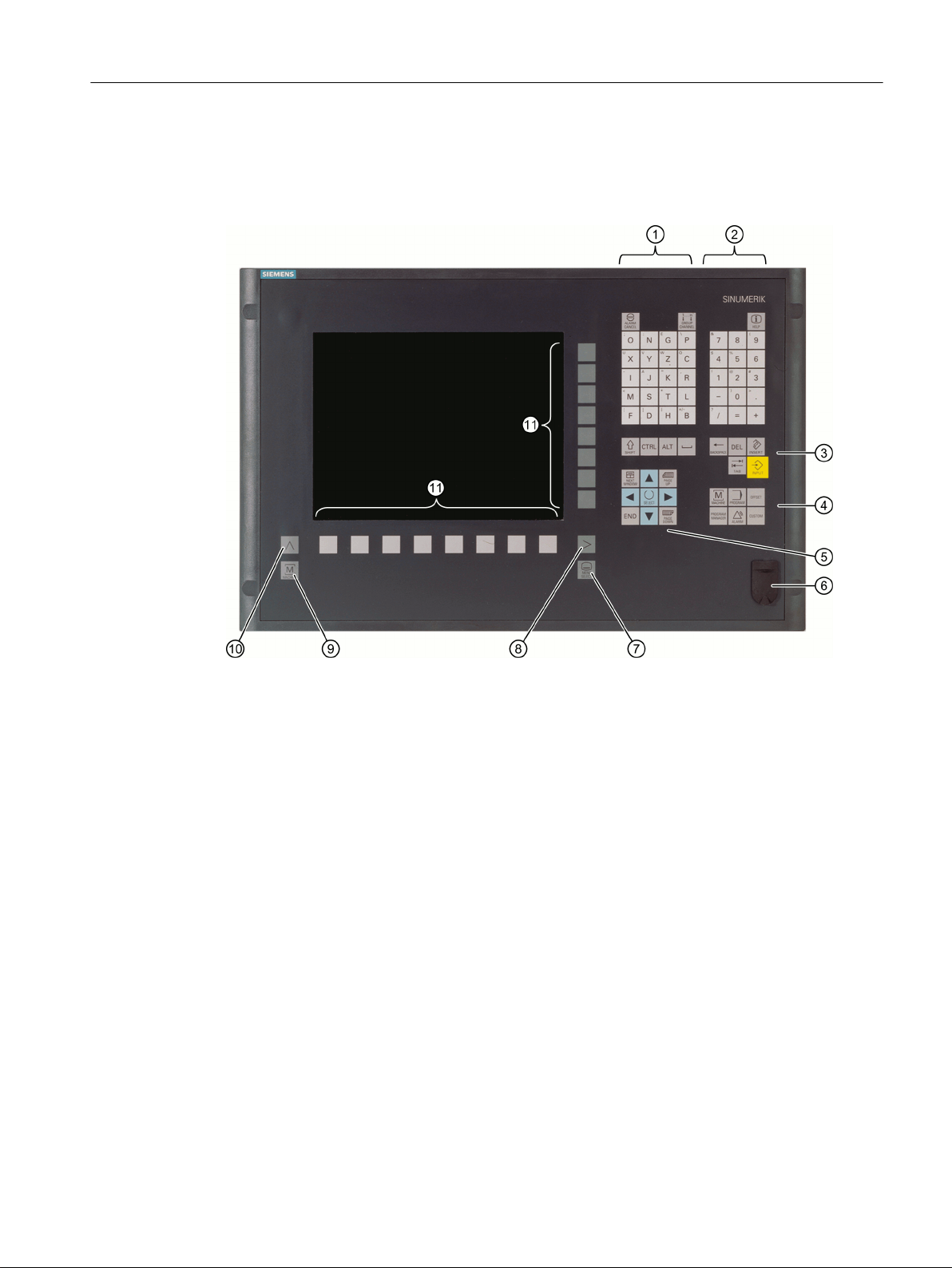
Operator controls and indicators
In this example, the OP 010 operator panel front is used to illustrate the components that are
available for operating the controller and machine tool.
Introduction
2.2 Operator panel fronts
① Alphabetic key group
With the <Shift> key pressed, you activate the special characters on keys with double assign‐
ments, and write in the uppercase.
Note: Depending on the particular configuration of your control system, uppercase letters are
always written
② Numerical key group
With the <Shift> key pressed, you activate the special characters on keys with double assign‐
ments.
③ Control key group
④ Hotkey group
⑤ Cursor key group
⑥ USB interface
⑦ Menu select key
⑧ Menu forward button
⑨ Machine area button
⑩ Menu back key
⑪ Softkeys
Turning
Operating Manual, 06/2019, A5E44903486B AB 29
Page 30

Introduction
2.2 Operator panel fronts
Further information
Further information about the OP 010 and other usable operator panel fronts can be found at:
● Operating Components Equipment Manual - Handheld Units (
support.industry.siemens.com/cs/ww/en/view/109736210)
● Equipment Manual OP 010 (https://support.industry.siemens.com/cs/ww/en/view/
109759204)
● Equipment Manual OP 012 (https://support.industry.siemens.com/cs/ww/en/view/
109741627)
● Equipment Manual OP 015A (https://support.industry.siemens.com/cs/ww/en/view/
109748600)
● Operating Components Equipment Manual - TCU 30.3 (https://
support.industry.siemens.com/cs/ww/en/view/109749929)
● HT 8 (https://support.industry.siemens.com/cs/ww/en/view/109763514)
2.2.2 Keys of the operator panel
The following keys and key combinations are available for operation of the control and the
machine tool.
Keys and key combinations
https://
Key Function
<ALARM CANCEL>
Cancels alarms and messages that are marked with this symbol.
<CHANNEL>
Advances for several channels.
<HELP>
Calls the context-sensitive online help for the selected window.
<NEXT WINDOW>
● Toggles between the windows.
● For a multi-channel view or for a multi-channel functionality,
switches within a channel gap between the upper and lower
window.
● Selects the first entry in selection lists and in selection fields.
● Moves the cursor to the beginning of a text.
* on USB keyboards use the <Home> or <Pos 1> key
*
Turning
30 Operating Manual, 06/2019, A5E44903486B AB
Page 31
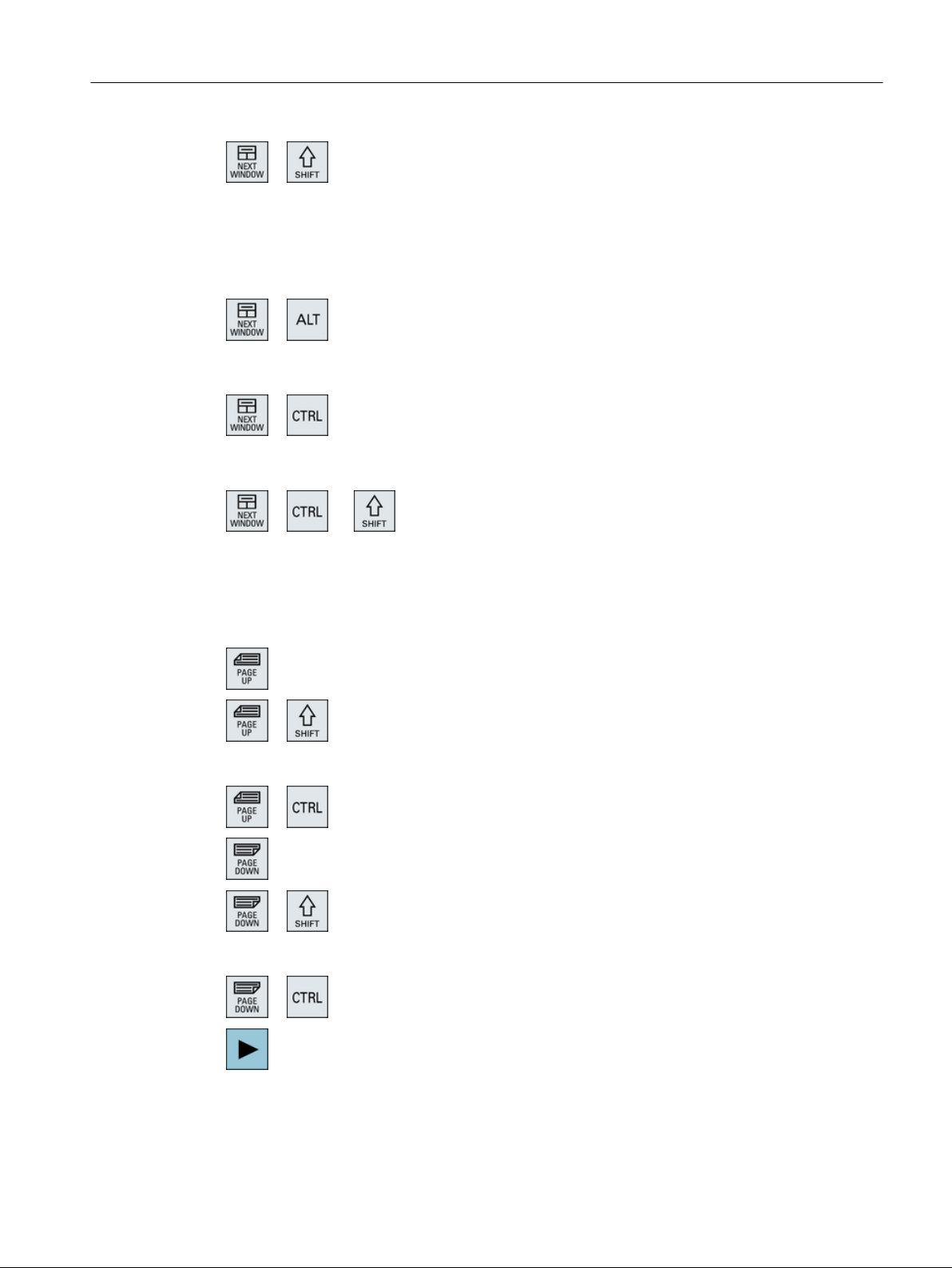
<NEXT WINDOW> + <SHIFT>
● Selects the first entry in selection lists and in selection fields.
● Moves the cursor to the beginning of a text.
● Selects a contiguous selection from the current cursor position
up to the target position.
● Selects a contiguous selection from the current cursor position
up to the beginning of a program block.
<NEXT WINDOW> + <ALT>
● Moves the cursor to the first object.
● Moves the cursor to the first column of a table row.
● Moves the cursor to the beginning of a program block.
<NEXT WINDOW> + <CTRL>
● Moves the cursor to the beginning of a program.
● Moves the cursor to the first row of the current column.
<NEXT WINDOW> + <CTRL> + <SHIFT>
● Moves the cursor to the beginning of a program.
● Moves the cursor to the first row of the current column.
● Selects a contiguous selection from the current cursor position
up to the target position.
● Selects a contiguous selection from the current cursor position
up to the beginning of the program.
<PAGE UP>
Scrolls upwards by one page in a window.
Introduction
2.2 Operator panel fronts
<PAGE UP> + <SHIFT>
In the program manager and in the program editor from the cursor
position, selects directories or program blocks up to the beginning of
the window.
<PAGE UP> + <CTRL>
Positions the cursor to the topmost line of a window.
<PAGE DOWN>
Scrolls downwards by one page in a window.
<PAGE DOWN> + <SHIFT>
In the program manager and in the program editor, from the cursor
position, selects directories or program blocks up to the end of the
window.
<PAGE DOWN> + <CTRL>
Positions the cursor to the lowest line of a window.
<Cursor right>
● Editing box
Opens a directory or program (e.g. cycle) in the editor.
● Navigation
Moves the cursor further to the right by one character.
Turning
Operating Manual, 06/2019, A5E44903486B AB 31
Page 32
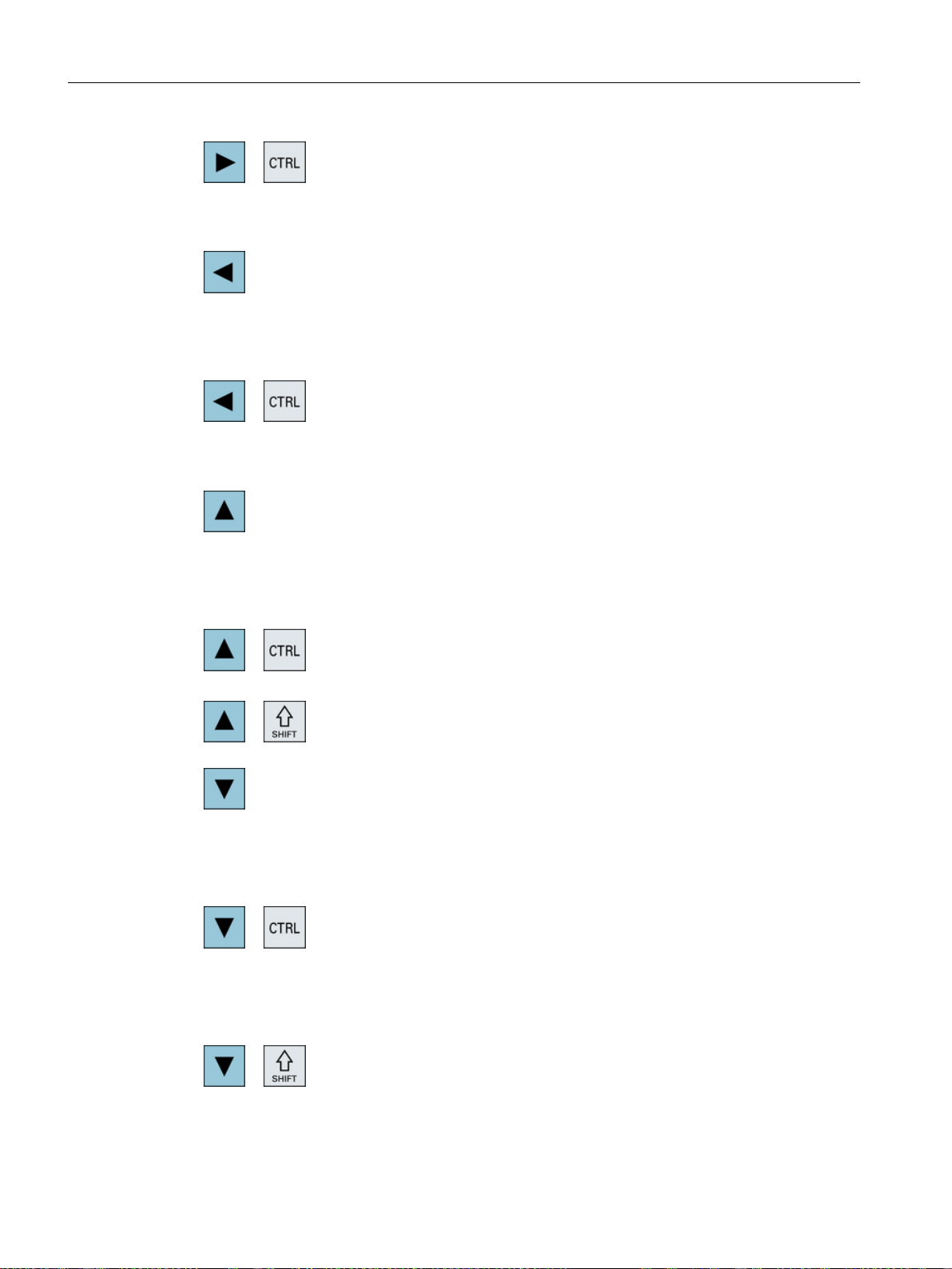
Introduction
2.2 Operator panel fronts
<Cursor right> + <CTRL>
● Editing box
Moves the cursor further to the right by one word.
● Navigation
Moves the cursor in a table to the next cell to the right.
<Cursor left>
● Editing box
Closes a directory or program (e.g. cycle) in the program editor.
If you have made changes, then these are accepted.
● Navigation
Moves the cursor further to the left by one character.
<Cursor left> + <CTRL>
● Editing box
Moves the cursor further to the left by one word.
● Navigation
Moves the cursor in a table to the next cell to the left.
<Cursor up>
● Editing box
Moves the cursor into the next upper field.
● Navigation
– Moves the cursor in a table to the next cell upwards.
– Moves the cursor upwards in a menu screen.
<Cursor up> + <Ctrl>
● Moves the cursor in a table to the beginning of the table.
● Moves the cursor to the beginning of a window.
<Cursor up> + <SHIFT>
In the program manager and in the program editor, selects a con‐
tiguous selection of directories and program blocks.
<Cursor down>
● Editing box
Moves the cursor downwards.
● Navigation
– Moves the cursor in a table to the next cell downwards.
– Moves the cursor in a window downwards.
<Cursor down> + <CTRL>
● Navigation
– Moves the cursor in a table to the end of the table.
– Moves the cursor to the end of a window.
● Simulation
Reduces the override.
<Cursor down> + <SHIFT>
In the program manager and in the program editor, selects a con‐
tiguous selection of directories and program blocks.
Turning
32 Operating Manual, 06/2019, A5E44903486B AB
Page 33
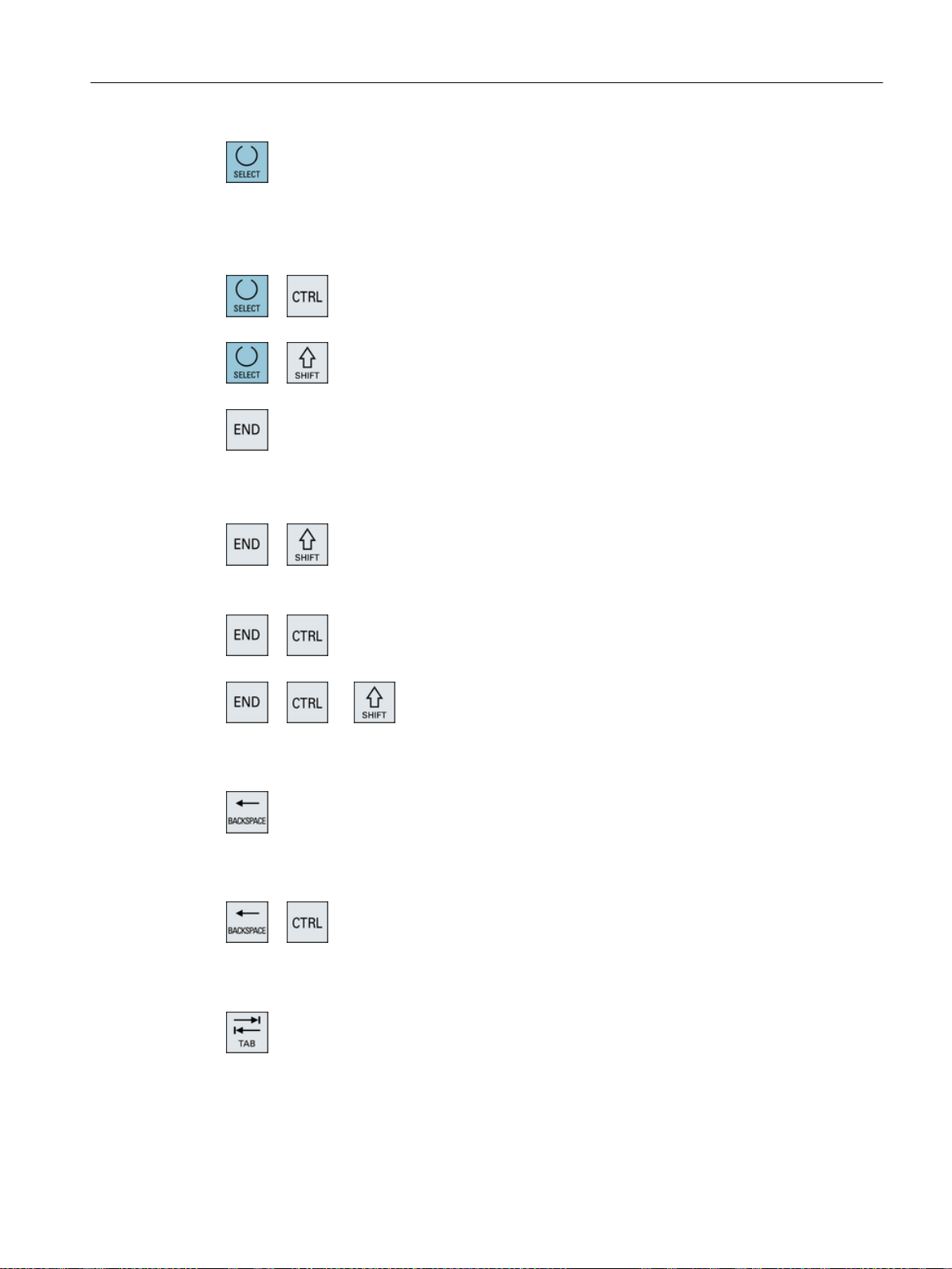
<SELECT>
Switches between several specified options in selection lists and in
selection boxes.
Activates checkboxes.
In the program editor and in the program manager, selects a pro‐
gram block or a program.
<SELECT> + <CTRL>
When selecting table rows, switches between selected and not se‐
lected.
<SELECT> + <SHIFT>
Selects in selection lists and in selection boxes the previous entry or
the last entry.
<END>
Moves the cursor to the last entry field in a window, to the end of a
table or a program block.
Selects the last entry in selection lists and in selection boxes.
<END> + <SHIFT>
Moves the cursor to the last entry.
Selects a contiguous selection from the cursor position up to the end
of a program block.
<END> + <CTRL>
Moves the cursor to the last entry in the last line of the actual column
or to the end of a program.
<END> + <CTRL> + <SHIFT>
Moves the cursor to the last entry in the last line of the actual column
or to the end of a program.
Selects a contiguous selection from the cursor position up to the end
of a program block.
<BACKSPACE>
● Editing box
Deletes a character selected to the left of the cursor.
● Navigation
Deletes all of the selected characters to the left of the cursor.
<BACKSPACE> + <CTRL>
● Editing box
Deletes a word selected to the left of the cursor.
● Navigation
Deletes all of the selected characters to the left of the cursor.
<TAB>
● In the program editor, indents the cursor by one character.
● In the program manager, moves the cursor to the next entry to
the right.
Introduction
2.2 Operator panel fronts
Turning
Operating Manual, 06/2019, A5E44903486B AB 33
Page 34
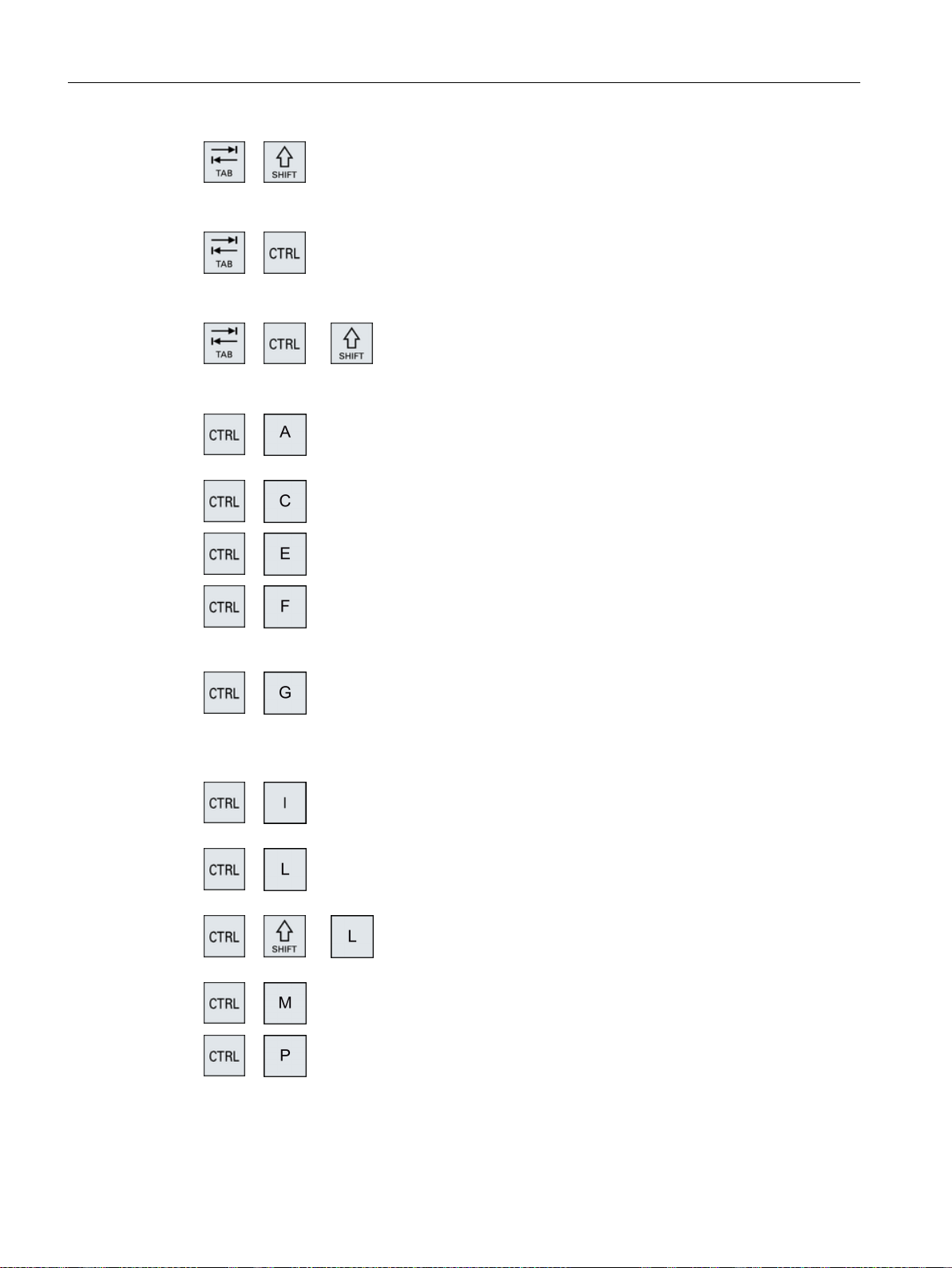
Introduction
2.2 Operator panel fronts
<CTRL> + <C>
<TAB> + <SHIFT>
● In the program editor, indents the cursor by one character.
● In the program manager, moves the cursor to the next entry to
the left.
<TAB> + <CTRL>
● In the program editor, indents the cursor by one character.
● In the program manager, moves the cursor to the next entry to
the right.
<Tab> + <Ctrl> + <Shift>
● In the program editor, indents the cursor by one character.
● In the program manager, moves the cursor to the next entry to
the left.
<CTRL> + <A>
In the actual window, selects all entries (only in the program editor
and program manager).
Copies the selected content.
<CTRL> + <E>
Calls the "Ctrl Energy" function.
<CTRL> + <F>
Opens the search dialog in the machine data and setting data lists,
when loading and saving in the MDI editor as well as in the program
manager and in the system data.
<CTRL> + <G>
● Switches in the program editor for ShopMill or ShopTurn
programs between the work plan and the graphic view.
● Switches in the parameter screen between the help display and
the graphic view.
<CTRL> + <I>
Calculates the program runtime up to or from the selected set/block
and displays a graphic representation of the times.
<CTRL> + <L>
Scrolls the actual user interface through all installed languages one
after the other.
<CTRL> + <SHIFT> + <L>
Scrolls the actual user interface through all installed languages in
the inverse sequence.
<CTRL> + <M>
Selects the maximum feedrate of 120% during the simulation.
<CTRL> + <P>
Generates a screenshot from the actual user interface and saves it
as file.
Turning
34 Operating Manual, 06/2019, A5E44903486B AB
Page 35
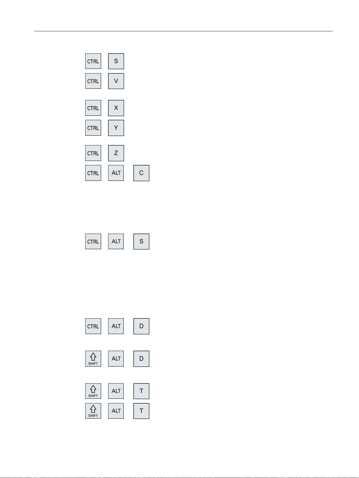
<CTRL> + <S>
Switches the single block in or out in the simulation.
<CTRL> + <V>
● Pastes text from the clipboard at the actual cursor position.
● Pastes text from the clipboard at the position of a selected text.
<CTRL> + <X>
Cuts out the selected text. The text is located in the clipboard.
<CTRL> + <Y>
Reactivates changes that were undone (only in the program edi‐
tor).
<CTRL> + <Z>
Undoes the last action (only in the program editor).
<CTRL> + <ALT> + <C>
Creates a complete standard archive (.ARC) on an external data
carrier (USB-FlashDrive) (for 840D sl / 828D).
Note:
The complete backup via this key combination is only suitable for
diagnostic purposes.
Note:
Please refer to the machine manufacturer's specifications.
<CTRL> + <ALT> + <S>
Creates a complete standard archive (.ARC) on an external data
carrier (USB-FlashDrive) (for 840D sl).
Creates a complete Easy Archive (.ARD) on an external data carrier
(USB-FlashDrive) (for 828D).
Note:
The complete backup (.ARC) via this key combination is only suit‐
able for diagnostic purposes.
Note:
Please refer to the machine manufacturer's specifications.
<CTRL> + <ALT> + <D>
Backs up the log files on the USB-FlashDrive. If a USB-FlashDrive
is not inserted, then the files are backed-up in the manufacturer's
area of the CF card.
<SHIFT> + <ALT> + <D>
Backs up the log files on the USB-FlashDrive. If a USB-FlashDrive
is not inserted, then the files are backed-up in the manufacturer's
area of the CF card.
<SHIFT> + <ALT> + <T>
Starts "HMI Trace".
Introduction
2.2 Operator panel fronts
<SHIFT> + <ALT> + <T>
Exits "HMI Trace".
Turning
Operating Manual, 06/2019, A5E44903486B AB 35
Page 36
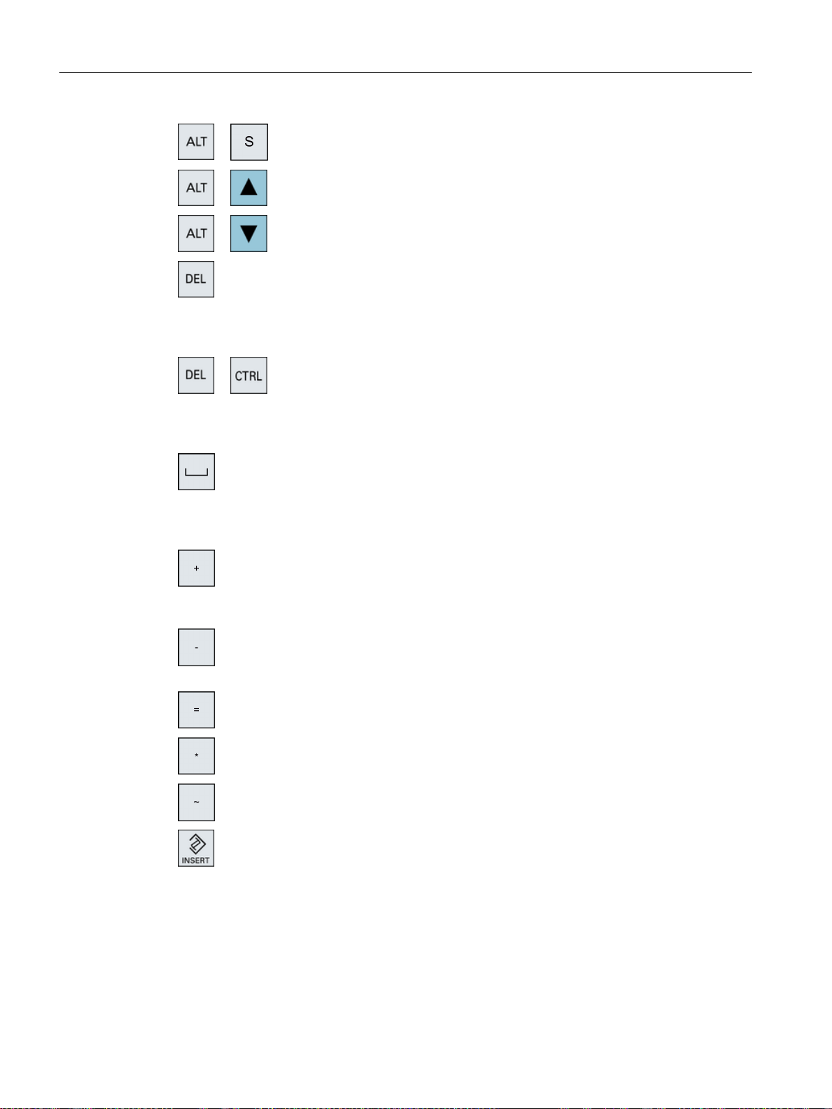
Introduction
2.2 Operator panel fronts
<ALT> + <S>
Opens the editor to enter Asian characters.
<ALT> + <Cursor up>
Moves the block start or block end up in the editor.
<ALT> + <Cursor down>
Moves the block start or block end down in the editor.
<DEL>
● Editing box
Deletes the first character to the right of the cursor.
● Navigation
Deletes all characters.
<DEL> + <CTRL>
● Editing box
Deletes the first word to the right of the cursor.
● Navigation
Deletes all characters.
<Spacebar>
● Editing box
Inserts a space.
● Switches between several specified options in selection lists and
in selection boxes.
<Plus>
● Opens a directory which contains the element.
● Increases the size of the graphic view for simulation and
traces.
<Minus>
● Closes a directory which contains the element.
● Reduces the size of the graphic view for simulation and traces.
<Equals>
Opens the calculator in the entry fields.
<Asterisk>
Opens a directory with all of the subdirectories.
<Tilde>
Changes the sign of a number between plus and minus.
<INSERT>
● Opens an editing window in the insert mode. Pressing the key
again, exits the window and the entries are undone.
● Opens a selection box and shows the selection possibilities.
● In the machining step program, enters an empty line for G code.
● Changes into the double editor or into the multi-channel view
from the edit mode into the operating mode. You can return to the
edit mode by pressing the key again.
Turning
36 Operating Manual, 06/2019, A5E44903486B AB
Page 37
+ <INSERT> + <SHIFT>
For G code programming, for a cycle call activates or deactivates
the edit mode.
<INPUT>
● Completes input of a value in the entry field.
● Opens a directory or a program.
● Inserts an empty program block if the cursor is positioned at the
end of a program block.
● Inserts a character to select a new line and the program block is
split up into two parts.
● In the G code, inserts a new line after the program block.
● In the machining step program, inserts a new line for G code e
● Changes into the double editor or into the multi-channel view
from the edit mode into the operating mode. You can return to the
edit mode by pressing the key again.
<ALARM> - only OP 010 and OP 010C
Calls the "Diagnosis" operating area.
Introduction
2.2 Operator panel fronts
<PROGRAM> - only OP 010 and OP 010C
Calls the "Program Manager" operating area.
<OFFSET> - only OP 010 and OP 010C
Calls the "Parameter" operating area.
<PROGRAM MANAGER> - only OP 010 and OP 010C
Calls the "Program Manager" operating area.
Menu forward key
Advances in the extended horizontal softkey bar.
Menu back key
Returns to the higher-level menu.
<MACHINE>
Calls the "Machine" operating area.
<MENU SELECT>
Calls the main menu to select the operating area.
Turning
Operating Manual, 06/2019, A5E44903486B AB 37
Page 38
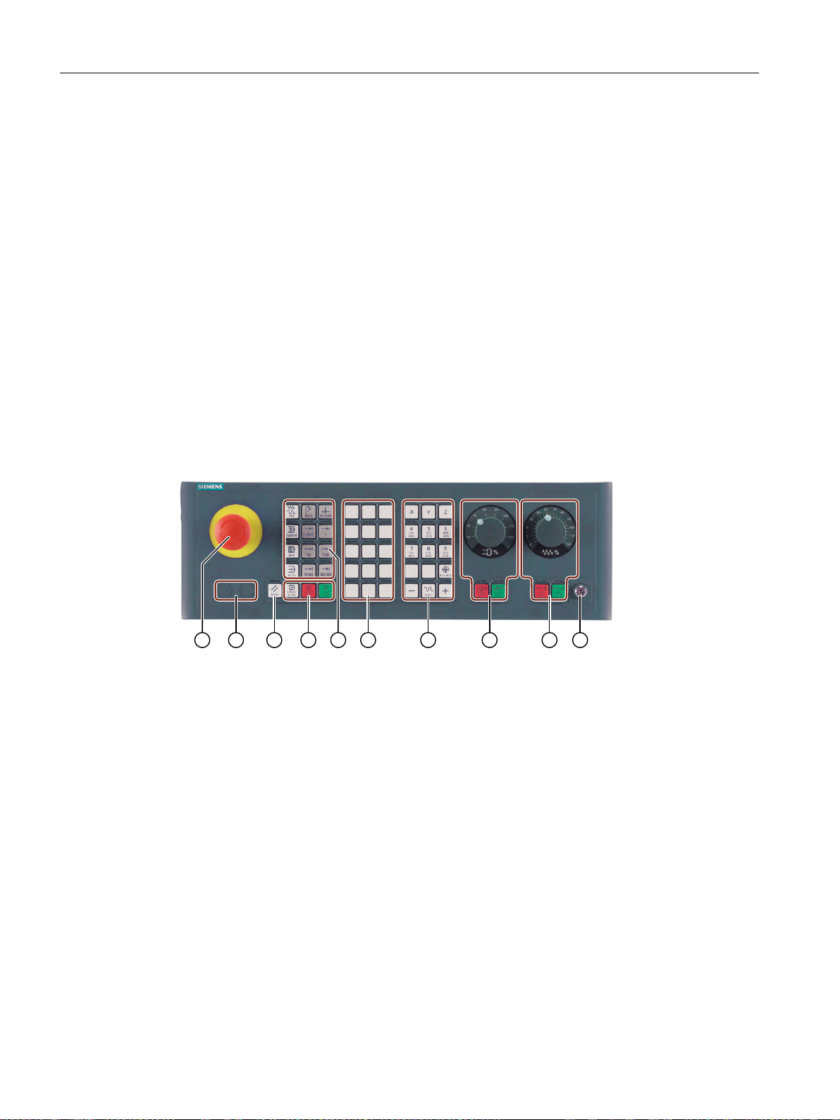
Introduction
2.3 Machine control panels
2.3 Machine control panels
2.3.1 Overview
The machine tool can be equipped with a machine control panel by Siemens or with a specific
machine control panel from the machine manufacturer.
You use the machine control panel to initiate actions on the machine tool such as traversing an
axis or starting the machining of a workpiece.
2.3.2 Controls on the machine control panel
In this example, the MCP 483C IE machine control panel is used to illustrate the operator
controls and displays of a Siemens machine control panel.
Overview
① EMERGENCY STOP button
② Installation locations for control devices (d = 16 mm)
③ RESET
④ Program control
⑤ Operating modes, machine functions
⑥ User keys T1 to T15
⑦ Traversing axes with rapid traverse override and coordinate switchover
⑧ Spindle control with override switch
⑨ Feed control with override switch
⑩ Keyswitch (four positions)
Turning
38 Operating Manual, 06/2019, A5E44903486B AB
Page 39
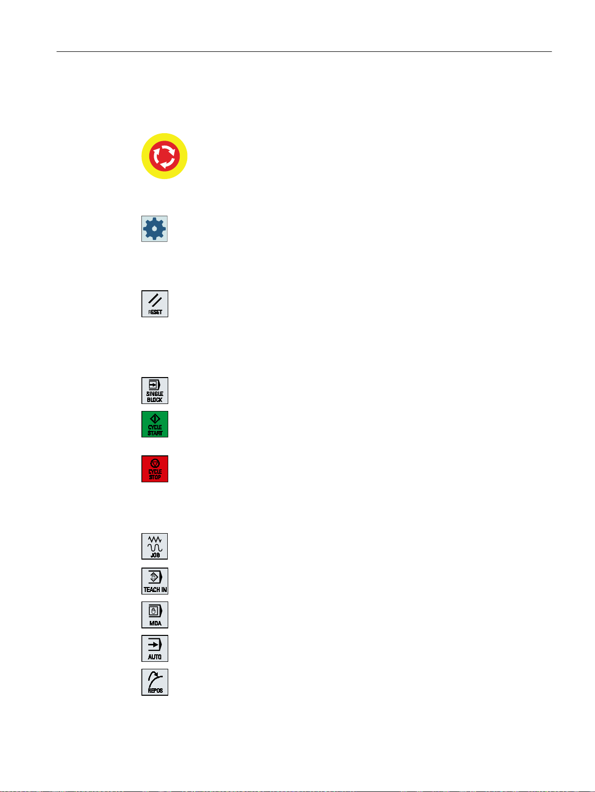
Operator controls
Introduction
2.3 Machine control panels
EMERGENCY STOP button
Press the button in situations where:
● life is at risk.
● there is the danger of a machine or workpiece being damaged.
All drives will be stopped with the greatest possible braking torque.
Machine manufacturer
For additional responses to pressing the EMERGENCY STOP button, please refer
to the machine manufacturer's instructions.
RESET
● Stop processing the current programs.
The NCK control remains synchronized with the machine. It is in its
initial state and ready for a new program run.
● Cancel alarm.
Program control
<SINGLE BLOCK>
Single block mode on/off.
<CYCLE START>
The key is also referred to as NC Start.
Execution of a program is started.
<CYCLE STOP>
The key is also referred to as NC Stop.
Execution of a program is stopped.
Operating modes, machine functions
<JOG>
Select "JOG" mode.
<TEACH IN>
Selecting the "Teach In" function
<MDI>
Select "MDI" mode.
<AUTO>
Select "AUTO" mode.
<REPOS>
Repositions, re-approaches the contour.
Turning
Operating Manual, 06/2019, A5E44903486B AB 39
Page 40
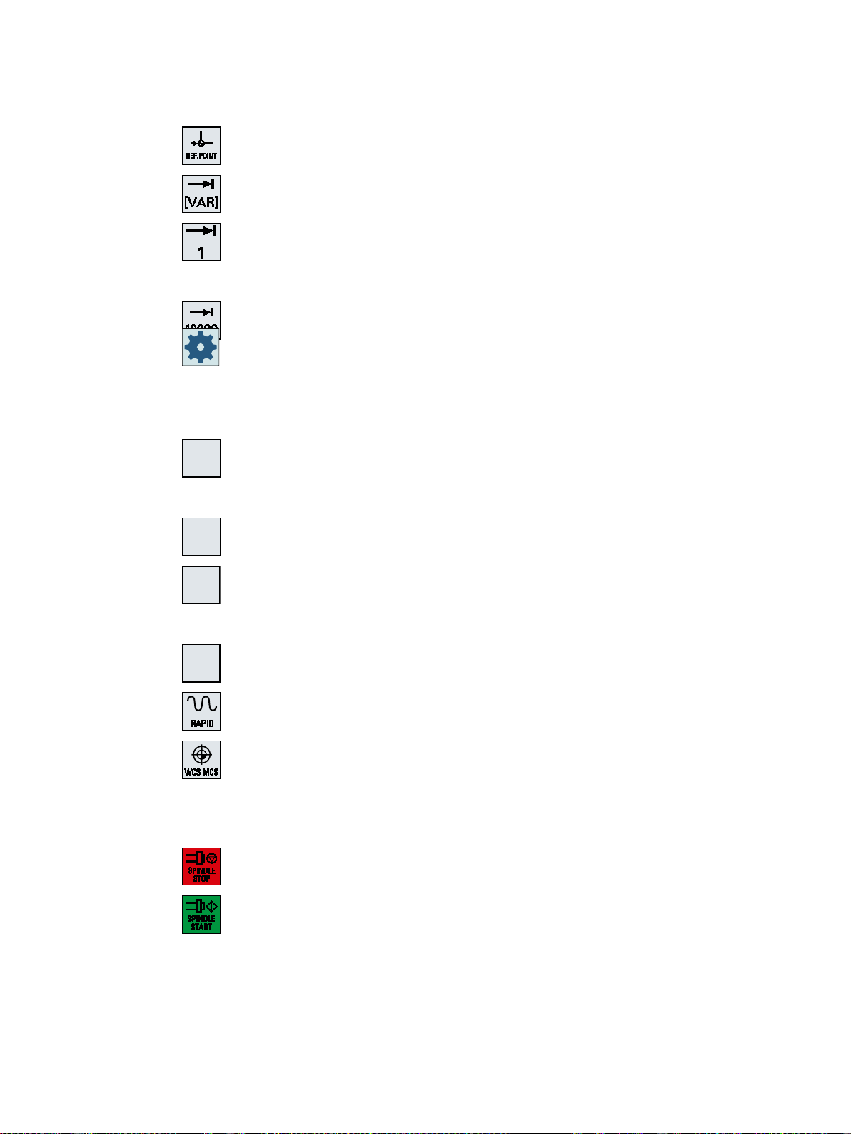
;
=
Introduction
2.3 Machine control panels
...
Traversing axes with rapid traverse override and coordinate switchover
<REF POINT>
Approach reference point.
Inc <VAR> (Incremental Feed Variable)
Incremental mode with variable increment size.
Inc (incremental feed)
Incremental mode with predefined increment size of
1, ..., 10000 increments.
Machine manufacturer
A machine data code defines how the increment value is interpreted.
Axis keys
Selects an axis.
...
Direction keys
Select the traversing direction.
...
<RAPID>
Traverse axis in rapid traverse while pressing the direction key.
<WCS MCS>
Switches between the workpiece coordinate system (WCS) and machine
coordinate system (MCS).
Spindle control with override switch
<SPINDLE STOP>
Stop spindle.
<SPINDLE START>
Spindle is enabled.
Turning
40 Operating Manual, 06/2019, A5E44903486B AB
Page 41

Feed control with override switch
<FEED STOP>
Stops execution of the running program and shuts down axis drives.
<FEED START>
Enable for program execution in the current block and enable for ramp-up
to the feedrate value specified by the program.
Introduction
2.3 Machine control panels
Turning
Operating Manual, 06/2019, A5E44903486B AB 41
Page 42
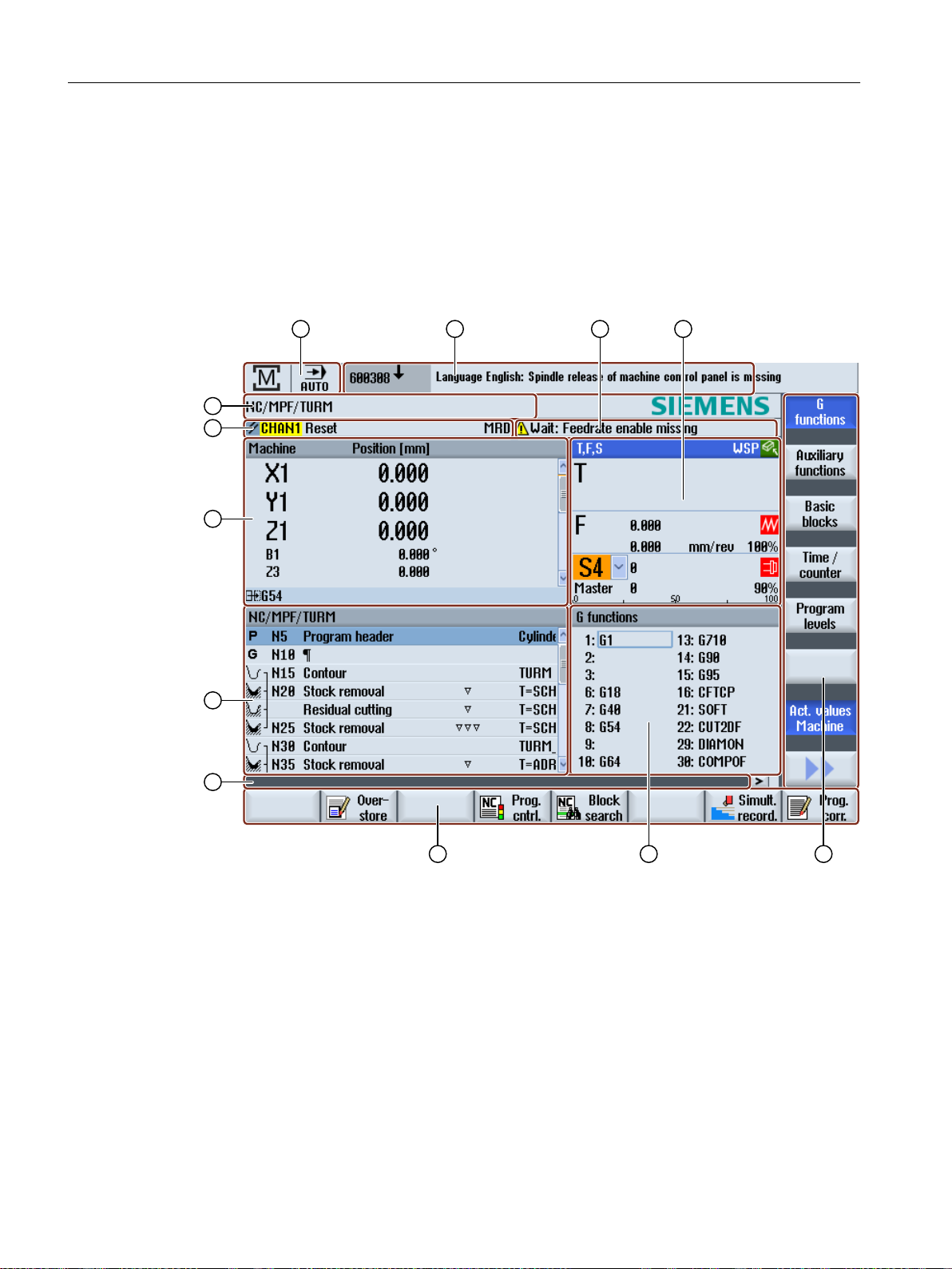
Introduction
2.4 User interface
2.4 User interface
2.4.1 Screen layout
Overview
① Active operating area and mode
② Alarm/message line
③ Channel operational messages
④ Display for
● Active tool T
● Current feedrate F
● Active spindle with current state (S)
● Spindle utilization rate in percent
⑤ Vertical softkey bar
⑥ Display active G functions, all G functions, H functions and input window for different functions
(e.g. skip blocks, program control)
⑦ Horizontal softkey bar
42 Operating Manual, 06/2019, A5E44903486B AB
Turning
Page 43

⑧ Dialog line to provide additional user notes
⑨ Operating window with program block display
⑩ Axis position display in the actual value window
⑪ Channel state and program control
⑫ Program name
2.4.2 Status display
The status display includes the most important information about the current machine status
and the status of the NCK. It also shows alarms as well as NC and PLC messages.
Depending on your operating area, the status display is made up of several lines:
● Large status display
The status display is made up of three lines in the "Machine" operating area.
● Small status display
In the "Parameter", "Program", "Program Manager", "Diagnosis" and "Start-up" operating
areas, the status display consists of the first line from the large display.
Introduction
2.4 User interface
Status display of "Machine" operating area
First line
Ctrl-Energy - power display
Display Meaning
The power display must be switched on in the status line.
Note
Information about configuration is available in the following reference:
System Manual "Ctrl-Energy", SINUMERIK 840D sl / 828D
Active operating area
Display Meaning
The machine is not productive.
The machine is productive and energy is being consumed.
The machine is feeding energy back into the supply system.
"Machine" operating area
With touch operation, you can change the operating area here.
"Parameter" operating area
"Program" operating area
"Program manager" operating area
Turning
Operating Manual, 06/2019, A5E44903486B AB 43
Page 44
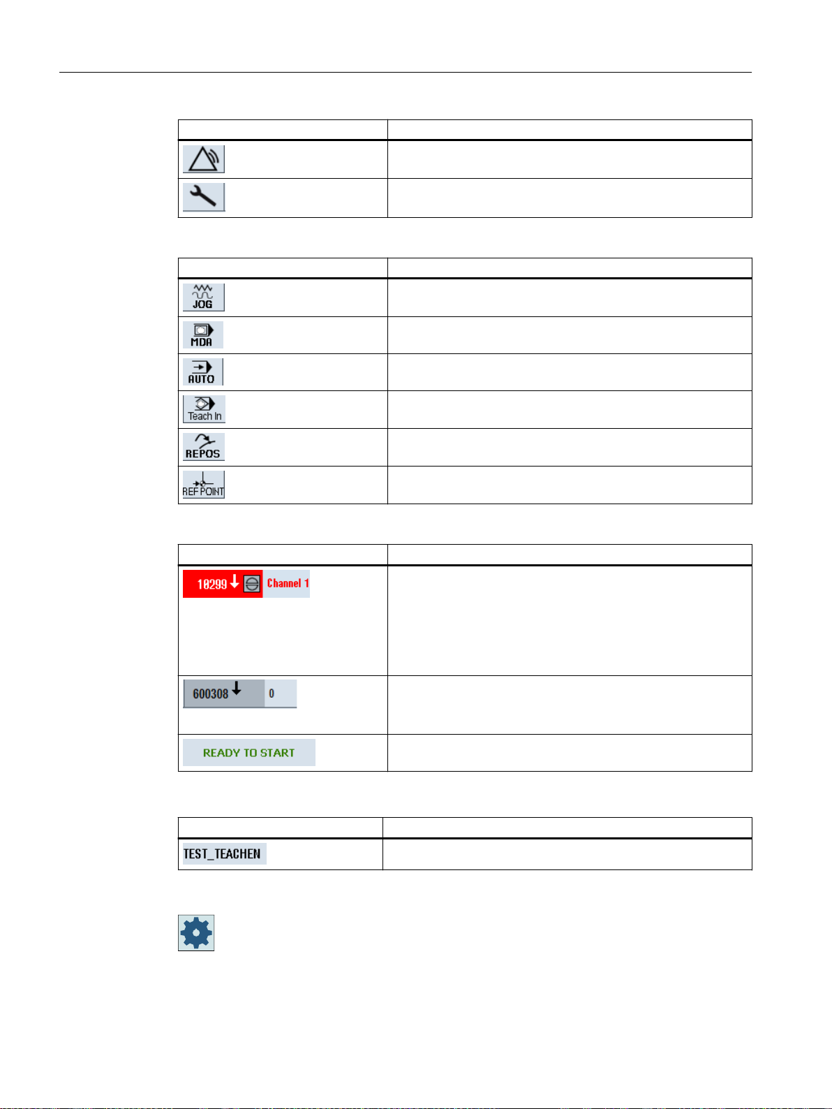
Introduction
2.4 User interface
Display Meaning
"Diagnostics" operating area
"Startup" operating area
Active mode or function
Display Meaning
"Jog" mode
"MDA" mode
"AUTO" mode
"TEACH IN" function
"REPOS" function
"REF POINT" function
Alarms and messages
Display Meaning
Alarm display
The alarm numbers are displayed in white lettering on a red
background. The associated alarm text is shown in red lettering.
An arrow indicates that several alarms are active.
An acknowledgment symbol indicates that the alarm can be ac‐
knowledged or canceled.
NC or PLC message
Message numbers and texts are shown in black lettering.
An arrow indicates that several messages are active.
Messages from NC programs do not have numbers and appear
in green lettering.
Second line
Display Meaning
Program path and program name
The displays in the second line can be configured.
Machine manufacturer
Please observe the information provided by the machine manufacturer.
Turning
44 Operating Manual, 06/2019, A5E44903486B AB
Page 45
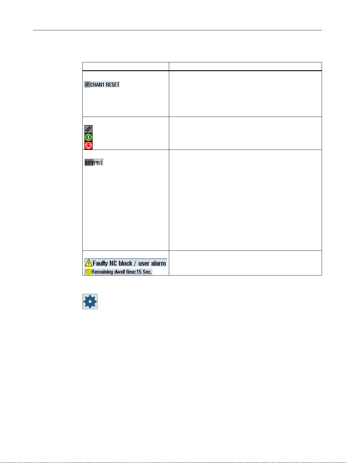
Third line
Display Meaning
Channel status display.
If the machine has several channels, then the channel name is
also displayed.
If there is only one channel, then only "Reset" is displayed as
channel status.
With touch operation, you can change the channel here.
Channel status display:
The program was canceled with "Reset".
The program is executed.
The program was interrupted with "Stop".
Display of active program controls:
PRT no axis motion
DRY dry run feedrate
RG0: reduced rapid traverse
M01: programmed stop 1
M101: programmed stop 2 (the designation is variable)
SB1: Single block, coarse (program stops only after blocks that
perform a machine function)
SB2: Calculation block (program stops after each block)
SB3: Single block, fine (program also only stops after blocks
which perform a machine function in cycles)
CST: configured stop (program stops at stop-relevant locations,
which you defined before the program starts)
Channel operational messages:
Stop: An operator action is usually required.
Wait: No operator action is required.
Introduction
2.4 User interface
The machine manufacturer settings determine which program controls are displayed.
Machine manufacturer
Please observe the information provided by the machine manufacturer.
2.4.3 Actual value window
The actual values of the axes and their positions are displayed.
Work/Machine
The displayed coordinates are based on either the machine coordinate system or the
workpiece coordinate system. The machine coordinate system (Machine), in contrast to the
workpiece coordinate system (Work), does not take any work offsets into consideration.
You can use the "Machine actual values" softkey to toggle between the machine coordinate
system and the workpiece coordinate system.
Turning
Operating Manual, 06/2019, A5E44903486B AB 45
Page 46
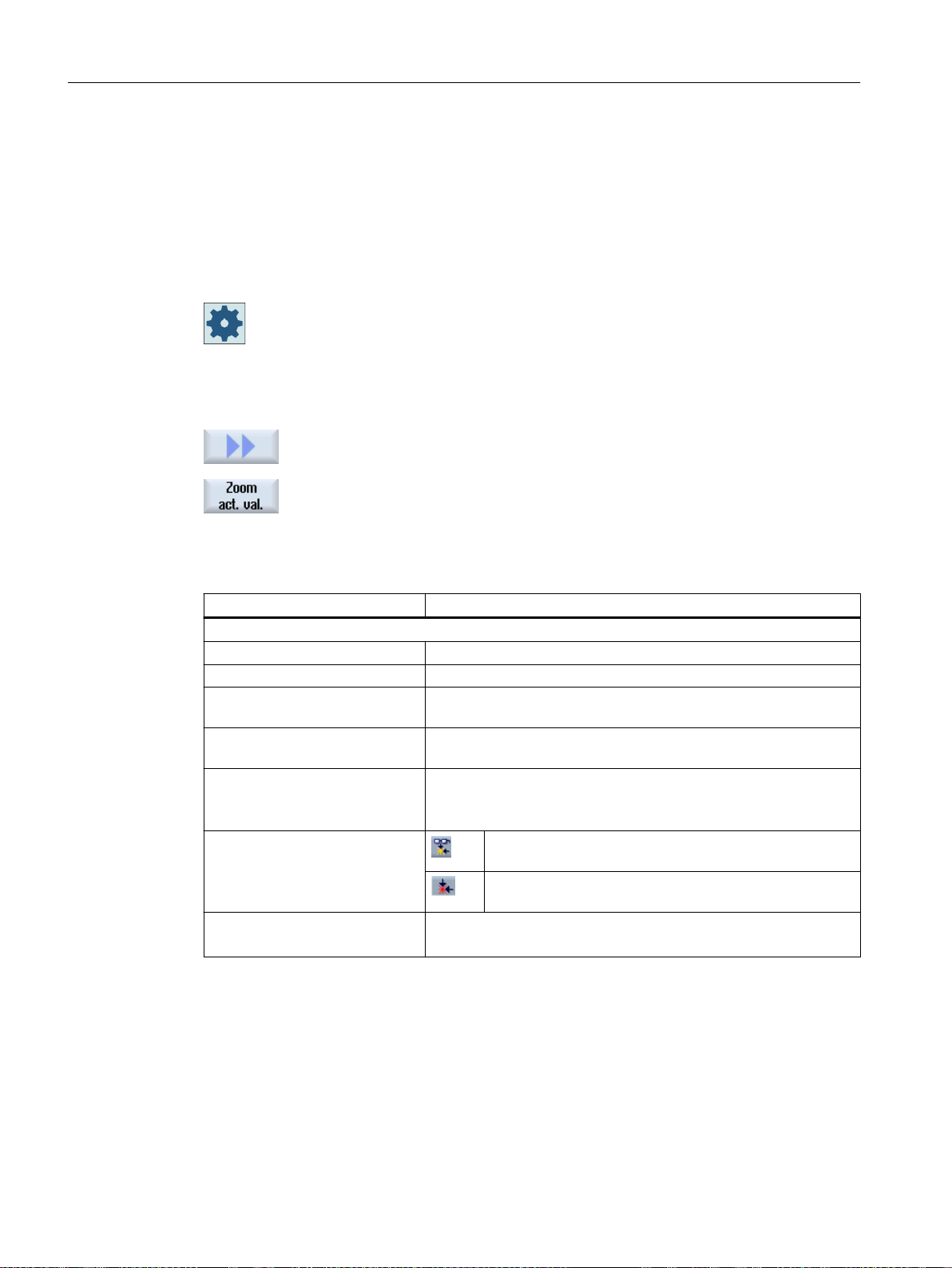
Introduction
2.4 User interface
Maximize display
The actual value display of the positions can also refer to the SZS coordinate system (settable
zero system). However the positions are still output in the Work.
The SZS coordinate system corresponds to the Work coordinate system, reduced by certain
components ($P_TRAFRAME, $P_PFRAME, $P_ISO4FRAME, $P_CYCFRAME), which are
set by the system when machining and are then reset again. By using the SZS coordinate
system, jumps into the actual value display are avoided that would otherwise be caused by the
additional components.
Machine manufacturer
Please observe the information provided by the machine manufacturer.
Press the ">>" and "Zoom act. val." softkeys.
Display overview
See also
Display Meaning
Header columns
Work/Machine Display of axes in selected coordinate system.
Position Position of displayed axes.
Display of distance-to-go The distance-to-go for the current NC block is displayed while the
program is running.
Feed/override The feed acting on the axes, as well as the override, are displayed
in the full-screen version.
REPOS offset The distances traversed in manual mode are displayed.
This information is only displayed when you are in the "REPOS"
function.
Collision avoidance Collision avoidance is activated for JOG, MDI and AUTO
modes.
Collision avoidance is deactivated for JOG, MDI and AU‐
TO modes.
Footer Display of active work offsets and transformations.
The T, F, S values are also displayed in the full-screen version.
Zero offsets (Page 117)
Set collision avoidance (Page 714)
Turning
46 Operating Manual, 06/2019, A5E44903486B AB
Page 47
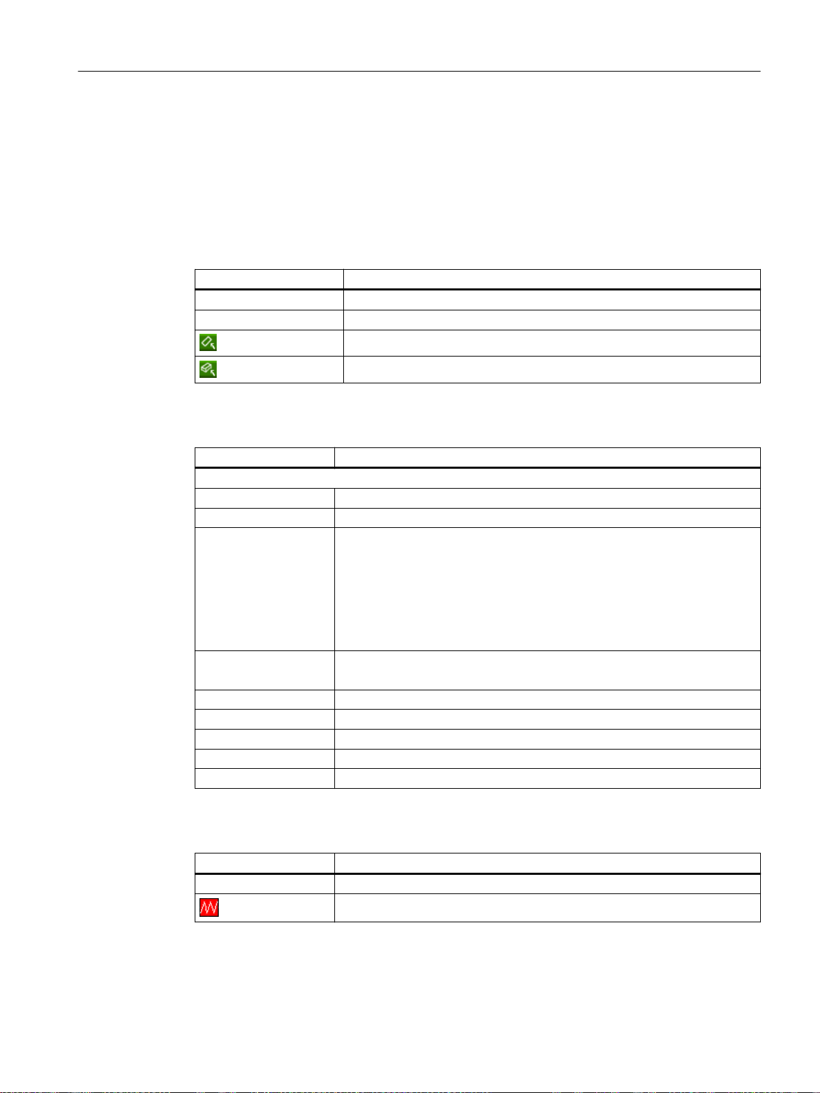
2.4.4 T,F,S window
The most important data concerning the current tool, the feedrate (path feed or axis feed in
JOG) and the spindle is displayed in the T, F, S window.
In addition to the "T, F, S" window name, the following information is also displayed:
Display Meaning
BC (example) Name of the tool carrier
Turning (example) Name of the active kinematic transformation
Tool data
Display Meaning
T
Tool name Name of the current tool
Location Location number of the current tool
D Cutting edge of the current tool
H H number (tool offset data record for DIN-ISO mode)
Ø Diameter of the current tool
R Radius of the current tool
L Length of the actual tool
Z Z value of the current tool
X X value of the current tool
Introduction
2.4 User interface
Active tool carrier rotated in the plane
Active tool carrier swiveled in space
The tool is displayed with the associated tool type symbol corresponding to
the actual coordinate system in the selected cutting edge position.
If the tool is swiveled, then this is taken into account in the display of the
cutting edge position.
In DIN-ISO mode the H number is displayed instead of the cutting edge num‐
ber.
If there is a valid D number, this is also displayed.
Feed data
Display Meaning
F
Feed disable
Turning
Operating Manual, 06/2019, A5E44903486B AB 47
Page 48
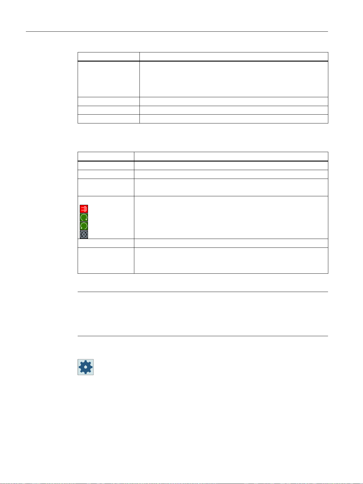
Introduction
2.4 User interface
Spindle data
Display Meaning
Actual feed value
If several axes traverse, is displayed for:
● "JOG" mode: Axis feed for the traversing axis
● "MDA" and "AUTO" mode: Programmed axis feed
Rapid traverse G0 is active
0.000 No feed is active
Override Display as a percentage
Display Meaning
S
S1 Spindle selection, identification with spindle number and main spindle
Speed Actual value (when spindle turns, display increases)
Setpoint (always displayed, also during positioning)
Symbol Spindle status
Spindle not enabled
Spindle is turning clockwise
Spindle is turning counterclockwise
Spindle is stationary
Override Display as a percentage
Spindle utilization
rate
Display between 0 and 100%
The upper limit value can be greater than 100%.
See machine manufacturer's specifications.
Note
Display of logical spindles
If the spindle converter is active, logical spindles are displayed in the workpiece coordinate
system. When switching over to the machine coordinate system, the physical spindles are
displayed.
Machine manufacturer
Please refer to the machine manufacturer's specifications.
2.4.5 Current block display
The window of the current block display shows the program blocks currently being executed.
Turning
48 Operating Manual, 06/2019, A5E44903486B AB
Page 49
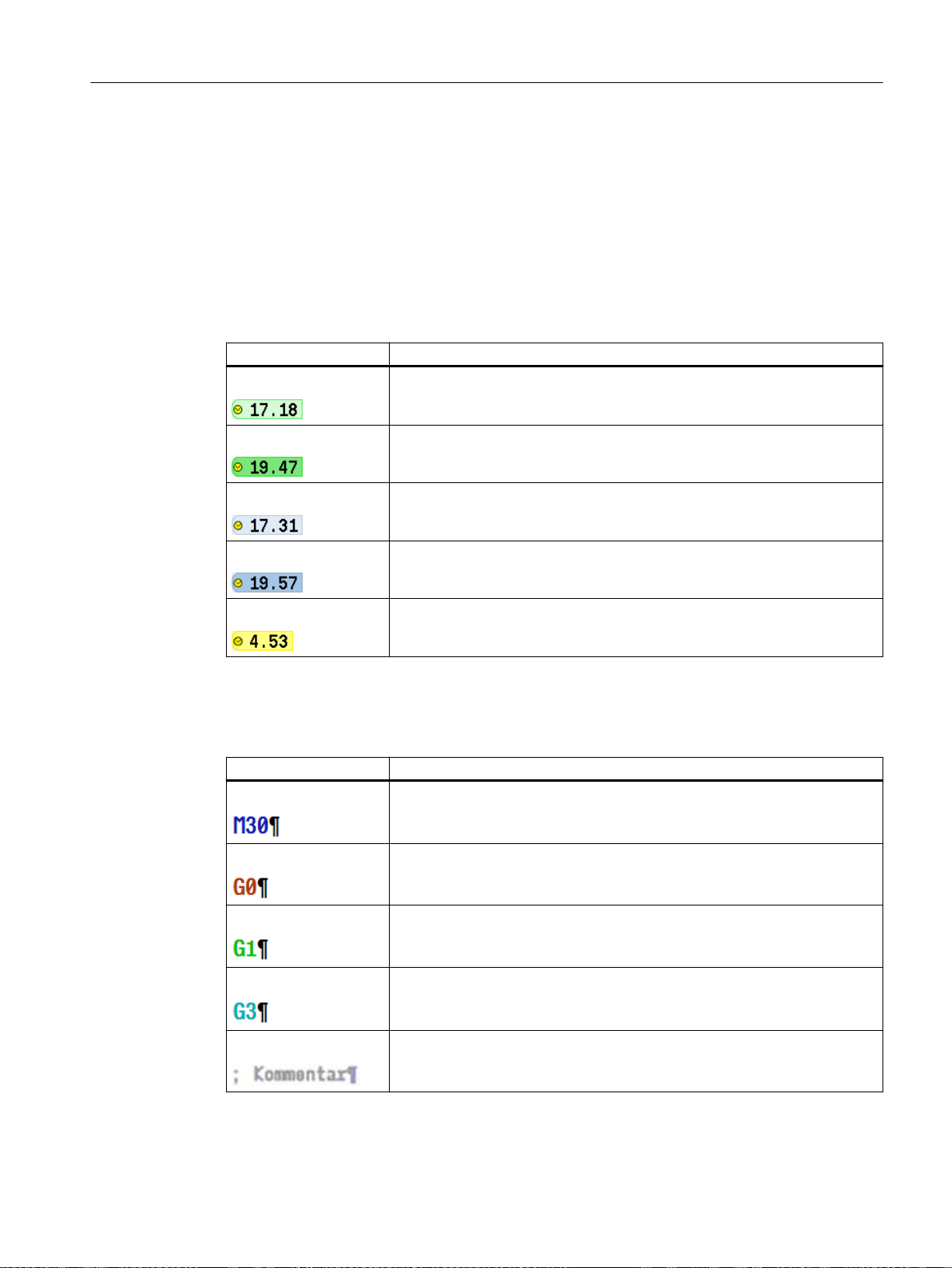
Display of current program
The following information is displayed in the running program:
● The workpiece name or program name is entered in the header line.
● The program block which is just being processed appears colored.
Display of the machining times
If you set that the machining times are to be recorded in the settings for automatic mode, the
measured times are shown at the end of the line as follows:
Display Meaning
Light green background Measured machining time of the program block (automatic mode)
Green background Measured machining time of the program group (automatic mode)
Light blue background Estimated machining time of the program block (simulation)
Introduction
2.4 User interface
Blue background Estimated machining time of the program group (simulation)
Yellow background Wait time (automatic mode or simulation)
Highlighting of selected G code commands or keywords
In the program editor settings, you can specify whether selected G code commands are to be
highlighted in color. The following colors are used as standard:
Display Meaning
Blue font D, S, F, T, M and H functions
Red font "G0" motion command
Green font "G1" motion command
Blue-green font "G2" or "G3" motion command
Gray font Comment
Turning
Operating Manual, 06/2019, A5E44903486B AB 49
Page 50

Introduction
2.4 User interface
Machine manufacturer
Editing a program directly
In the Reset state, you can edit the current program directly.
2. Place the cursor at the relevant position and edit the program block.
You can define further highlight colors in the "sleditorwidget.ini" configuration file.
Please refer to the machine manufacturer's instructions.
1. Press the <INSERT> key.
Direct editing is only possible for G code blocks in the NC memory, not for
external execution.
3. Press the <INSERT> key to exit the program and the edit mode again.
See also
Setting for automatic mode (Page 232)
2.4.6 Operation via softkeys and buttons
Operating areas/operating modes
The user interface consists of different windows featuring eight horizontal and eight vertical
softkeys.
You operate the softkeys with the keys next to the softkey bars.
You can display a new window or execute functions using the softkeys.
The operating software is sub-divided into six operating areas (machine, parameter, program,
program manager, diagnosis, startup), three operating modes and four functions (JOG, MDI,
AUTO, TEACH IN, REF. POINT, REPOS, single block).
Changing the operating area
Press the <MENU SELECT> key and select the desired operating area using
the horizontal softkey bar.
You can call the "Machine" operating area directly using the key on the operator panel.
Press the <MACHINE> key to select the "machine" operating area.
Turning
50 Operating Manual, 06/2019, A5E44903486B AB
Page 51
Introduction
2.4 User interface
Changing the operating mode
You can select a mode or function directly with the keys on the machine control panel or the
vertical softkeys in the main menu.
General keys and softkeys
When the symbol appears to the right of the dialog line on the user inter‐
face, you can change the horizontal softkey bar within an operating area. To do
so, press the menu forward key.
The symbol indicates that you are in the expanded softkey bar.
Pressing the key again will take you back to the original horizontal softkey bar.
Use the ">>" softkey to open a new vertical softkey bar.
Use the "<<" softkey to return to the previous vertical softkey bar.
Use the "Return" softkey to close an open window.
Use the "Cancel" softkey to exit a window without accepting the entered values
and return to the next highest window.
When you have entered all the necessary parameters in the parameter screen
form correctly, you can close the window and save the parameters using the
"Accept" softkey. The values you entered are applied to a program.
Use the "OK" softkey to initiate an action immediately, e.g. to rename or delete
a program.
2.4.7 Entering or selecting parameters
When setting up the machine and during programming, you must enter various parameter
values in the entry fields. The background color of the fields provides information on the status
of the entry field.
Orange background The input field is selected
Light orange background The input field is in edit mode
Pink background The entered value is incorrect
Selecting parameters
Some parameters require you to select from a number of options in the input field. Fields of this
type do not allow you to type in a value.
The selection symbol is displayed in the tooltip:
Turning
Operating Manual, 06/2019, A5E44903486B AB 51
Page 52
Introduction
2.4 User interface
Procedure
Associated selection fields
There are selection fields for various parameters:
● Selection of units
● Changeover between absolute and incremental dimensions
1. Keep pressing the <SELECT> key until the required setting or unit is
selected.
The <SELECT> key only works if there are several selection options
available.
- OR Press the <INSERT> key.
The selection options are displayed in a list.
2. Select the required setting using the <Cursor down> and <Cursor up>
keys.
3. If required, enter a value in the associated input field.
4. Press the <INPUT> key to complete the parameter input.
Changing or calculating parameters
If you only want to change individual characters in an input field rather than overwriting the
entire entry, switch to insertion mode.
In this mode, you can also enter simple calculation expressions, without having to explicitly call
the calculator.
Note
Functions of the calculator
Function calls of the calculator are not available in the parameter screens of the cycles and
functions in the "Program" operating area.
Press the <INSERT> key.
The insert mode is activated.
You can navigate within the input field using the <Cursor left> and <Cur‐
sor right> keys.
Turning
52 Operating Manual, 06/2019, A5E44903486B AB
Page 53
Introduction
2.4 User interface
Use the <BACKSPACE> and <DEL> key to delete individual characters.
Enter the value or the calculation.
Close the value entry using the <INPUT> key and the result is transferred
into the field.
Accepting parameters
When you have correctly entered all necessary parameters, you can close the window and
save your settings.
You cannot accept the parameters if they are incomplete or obviously erroneous. In this case,
you can see from the dialog line which parameters are missing or were entered incorrectly.
Press the "OK" softkey.
- OR Press the "Accept" softkey.
2.4.8 Pocket calculator
The calculator allows you to calculate values for entry fields. It is possible to choose between
a simple standard calculator and the extended view with mathematical functions.
Using the calculator
● You can simply use the calculator at the touch panel.
● Without a touch panel, you can use the calculator using the mouse.
Procedure
1. Position the cursor on the desired entry field.
2. Press the <=> key.
3. Press the <min> key if you would like to work with the standard calculator.
Press the <extend> key to switch to the extended view.
The calculator is displayed.
- OR -
4. Input the arithmetic statement.
You can use functions, arithmetic symbols, numbers, and commas.
Turning
Operating Manual, 06/2019, A5E44903486B AB 53
Page 54
Introduction
2.4 User interface
5. Press the equals symbol on the calculator.
- OR Press the "Calculate" softkey.
- OR Press the <INPUT> key.
The new value is calculated and displayed in the entry field of the calcu‐
lator.
6. Press the "Accept" softkey.
The calculated value is accepted and displayed in the entry field of the
window.
2.4.9 Pocket calculator functions
The called operations continue to be displayed in the entry field of the calculator until the value
is calculated. This allows you to subsequently modify entries and to nest functions.
The following save and delete functions are provided for modifications:
Key Function
Buffer value (Memory Save)
Retrieve from buffer memory (Memory Recall )
Delete buffer memory contents (Memory Clear)
Delete individual character (Backspace)
Delete expression (Clear Element)
Delete all entries (Clear)
Nesting functions
Various possibilities are available for the nesting of functions as follows:
● Position the cursor within the bracket of the function call and supplement the argument with
an additional function.
● Highlight the expression which is to be used as an argument in the entry line and then press
the desired function key.
Turning
54 Operating Manual, 06/2019, A5E44903486B AB
Page 55
Percentage calculation
The calculator supports the calculation of a percentage, as well as changing of a basic value by
a percentage. Press the following keys in this regard:
Example: Percentage
4 50 2
Example: Change by percentage
4 50 6
Calculating trigonometric functions
1. Check whether the angles are specified in radians "RAD" or in degrees
2. Press the "RAD" key to calculate the trigonometric functions in degrees
Press the "DEG" key to calculate the trigonometric functions in radian.
3.4.Press the key for the desired trigonometric function, e.g. "SIN".
...
Introduction
2.4 User interface
"DEG".
"DEG".
The designation of the key changes to "DEG".
- OR -
The designation of the key changes to "RAD".
Enter the numerical value.
Further mathematical functions
Press the keys in the specified order:
Square number
Num‐
ber
Square root
Num‐
ber
Exponential function
Base num‐
ber
Residue class calculation
Number Divider
Absolute value
Turning
Operating Manual, 06/2019, A5E44903486B AB 55
Exponent
Page 56
Introduction
2.4 User interface
Num‐
ber
Integer component
Num‐
ber
Conversion between millimeters and inches
1. Enter the numerical value.
2. Press the "MM" key to convert inches to millimeters.
The key is highlighted in blue.
- OR -
Press the "INCH" key to convert millimeters to inches.
The button is highlighted in blue.
3. Press the "=" key on the calculator.
The calculated value is displayed in the entry field. The key for the unit is
highlighted in gray once again.
2.4.10 Context menu
When you right-click, the context menu opens and provides the following functions:
● Cut
Cut Ctrl+X
● Copy
Copy Ctrl+C
● Paste
Paste Ctrl+V
Program editor
Additional functions are available in the editor
● Undo the last change
Undo Ctrl+Z
● Redo the changes that were undone
Redo Ctrl+Y
Up to 50 changes can be undone.
Turning
56 Operating Manual, 06/2019, A5E44903486B AB
Page 57
2.4.11 Changing the user interface language
Procedure
1. Select the "Start-up" operating area.
2. Press the "Change language" softkey.
The "Language selection" window opens. The language set last is se‐
lected.
3. Position the cursor on the desired language.
4. Press the "OK" softkey.
- OR Press the <INPUT> key.
Introduction
2.4 User interface
The user interface changes to the selected language.
Note
Changing the language directly on the input screens
You can switch between the user interface languages available on the controller directly on the
user interface by pressing the key combination <CTRL + L>.
2.4.12 Entering Chinese characters
2.4.12.1 Function - input editor
Using the input editor IME (Input Method Editor), you can select Asian characters on classic
panels (without touch operation) where you enter the phonetic notation. These characters are
transferred into the user interface.
Note
Call the input editor with <Alt + S>
The input editor can only be called there where it is permissible to enter Asian characters.
The editor is available for the following Asian languages:
● Simplified Chinese
● Traditional Chinese
Turning
Operating Manual, 06/2019, A5E44903486B AB 57
Page 58
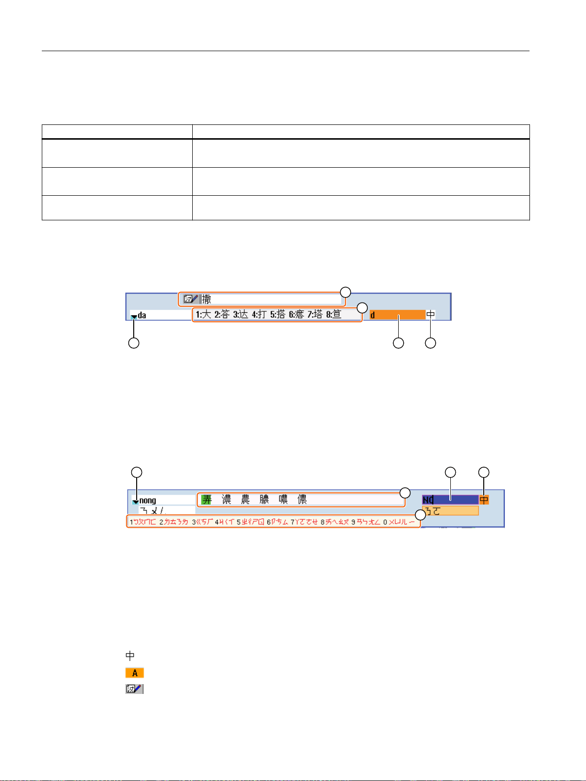
Introduction
2.4 User interface
Input types
Input type Description
Pinyin input Latin letters are combined phonetically to denote the sound of the character.
The editor lists all of the characters from the dictionary that can be selected.
Zhuyin input
(only traditional Chinese)
Entering Latin letters The characters that are entered are directly transferred into the input field, from where
Non-Latin letters are combined phonetically to denote the sound of the character.
The editor lists all of the characters from the dictionary that can be selected.
the editor was called.
Structure of the editor
① Phonetic sound selection from the dictionary
② Learning function of the dictionary
③ Listed characters
④ Phonetic sound input
⑤ Function selection
Figure 2-1 Example: Pinyin input
① Phonetic sound selection from the dictionary
② Listed characters (for the input field)
③ Listed characters (for phonetic sound input)
④ Phonetic sound input
⑤ Function selection
Figure 2-2 Example: Zhuyin input
Functions
Pinyin input
Entering Latin letters
Editing the dictionary
58 Operating Manual, 06/2019, A5E44903486B AB
Turning
Page 59
Dictionaries
The simplified Chinese and traditional Chinese dictionaries that are supplied can be expanded:
● If you enter new phonetic notations, the editor creates a new line. The entered phonetic
notation is broken down into known phonetic notations. Select the associated character for
each component. The compiled characters are displayed in the additional line. Accept the
new word into the dictionary and into the input field by pressing the <Input> key.
● Using any Unicode editor, you can enter new phonetic notations into a text file. These
phonetic notations are imported into the dictionary the next time that the input editor is
started.
2.4.12.2 Entering Asian characters
Precondition
The control has been switched over to Chinese.
Introduction
2.4 User interface
Procedure
Editing characters using the Pinyin method
1. Open the screen form and position the cursor on the input field.
Press the <Alt +S> keys.
+
2. Enter the desired phonetic notation using Latin letters. Use the upper
4. Keeping the <Cursor down> key pressed, displays all the entered pho‐
6. Press the number key to insert the associated character.
Editing characters using the Zhuyin method (only traditional Chinese)
The editor is displayed.
input field for traditional Chinese.
3. Press the <Cursor down> key to reach the dictionary.
netic notations and the associated selection characters.
5. Press the <BACKSPACE> softkey to delete entered phonetic notations.
When a character is selected, the editor records the frequency with which
it is selected for a specific phonetic notation and offers this character at
the top of the list when the editor is next opened.
Turning
Operating Manual, 06/2019, A5E44903486B AB 59
Page 60
Introduction
2.4 User interface
1. Open the screen form and position the cursor on the input field.
Press the <Alt +S> keys.
+
2. Enter the desired phonetic notation using the numerical block.
4. Keeping the <Cursor down> key pressed, displays all the entered pho‐
The editor is displayed.
Each number is assigned a certain number of letters that can be selected
by pressing the numeric key one or several times.
3. Press the <Cursor down> key to reach the dictionary.
netic notations and the associated selection characters.
5. Press the <BACKSPACE> softkey to delete entered phonetic notations.
6. To select the associated character, press the <cursor right> or <cursor
left> keys.
7. Press the <input> key to enter the character.
2.4.12.3 Editing the dictionary
Learning function of the input editor
Requirement:
The control has been switched over to Chinese.
An unknown phonetic notation has been entered into the input editor.
1. The editor provides a further line in which the combined characters and
2. Press the number key to insert the associated character into the addi‐
3. Repeat step 2 until the complete phonetic notation has been compiled.
phonetic notations are displayed.
The first part of the phonetic notation is displayed in the field for selecting
the phonetic notation from the dictionary. Various characters are listed
for this particular phonetic notation.
tional line.
The next part of the phonetic notation is displayed in the field for selecting
the phonetic notation from the dictionary.
Turning
60 Operating Manual, 06/2019, A5E44903486B AB
Page 61
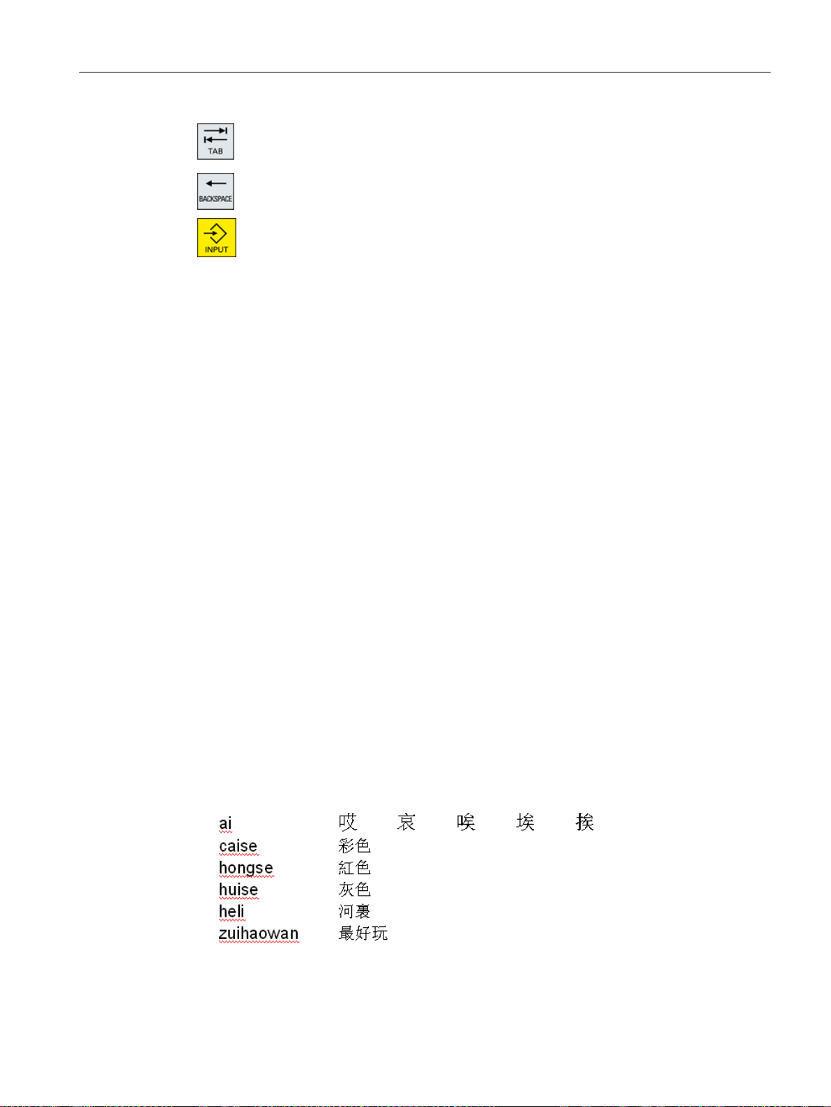
Importing a dictionary
A dictionary can now be generated using any Unicode editor by attaching the corresponding
Chinese characters to the pinyin phonetic spelling. If the phonetic spelling contains several
Chinese characters, then the line must not contain any additional match. If there are several
matches for one phonetic spelling, then these must be specified in the dictionary line by line.
Otherwise, several characters can be specified for each line.
The generated file should be saved in the UTF8 format under the name dictchs.txt (simplified
Chinese) or dictcht.txt (traditional Chinese).
Line structure:
Introduction
2.4 User interface
Press the <TAB> key to toggle between the compiled phonetic notation
field and the phonetic notation input.
Compiled characters are deleted using the <BACKSPACE> key.
4. Press the <input> key to transfer the compiled phonetic notation to the
dictionary and the input field.
Pinyin phonetic spelling <TAB> Chinese characters <LF>
OR
Pinyin phonetic spelling <TAB> Chinese character1<TAB> Chinese character2 <TAB> …
<LF>
<TAB> - tab key
<LF> - line break
Store the created dictionary in one of the following paths:
../user/sinumerik/hmi/ime/
../oem/sinumerik/hmi/ime/
When the Chinese editor is called the next time, it enters the content of the dictionary into the
system dictionary.
Example:
Turning
Operating Manual, 06/2019, A5E44903486B AB 61
Page 62
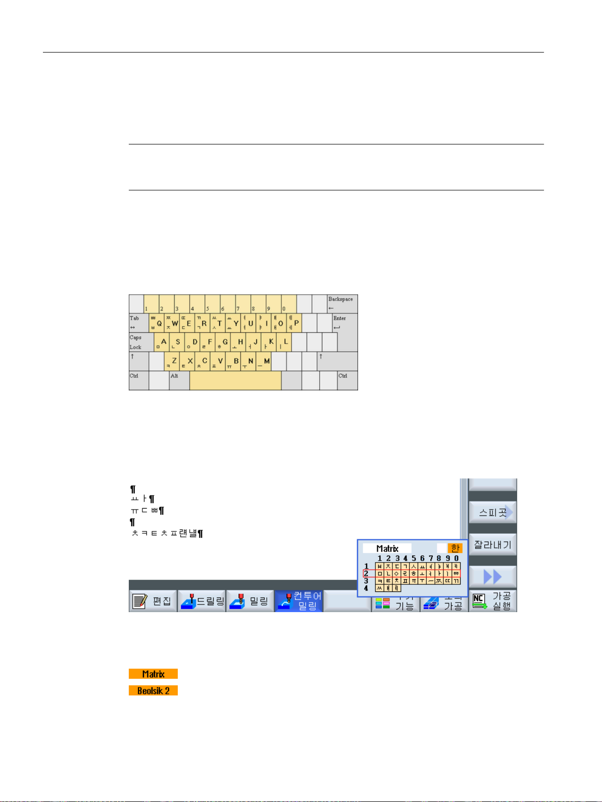
Introduction
2.4 User interface
2.4.13 Entering Korean characters
You can enter Korean characters in the input fields on classic panels (without touch operation)
using the input editor IME (Input Method Editor).
Note
You require a special keyboard to enter Korean characters. If this is not available, then you can
enter the characters using a matrix.
Korean keyboard
To enter Korean characters, you will need a keyboard with the keyboard assignment shown
below. In terms of key layout, this keyboard is the equivalent of an English QWERTY keyboard
and individual events must be grouped together to form syllables.
Structure of the editor
Functions
Editing characters using a matrix
Editing characters using the keyboard
Turning
62 Operating Manual, 06/2019, A5E44903486B AB
Page 63
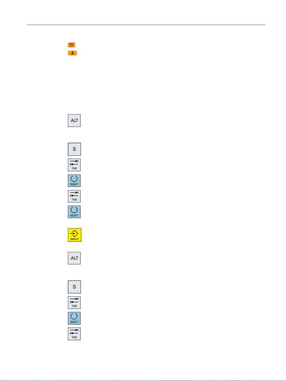
Precondition
Procedure
Entering Korean characters
Entering Latin letters
The control has been switched over to Korean.
Editing characters using the keyboard
1. Open the screen form and position the cursor on the input field.
Press the <Alt +S> keys.
+
The editor is displayed.
Introduction
2.4 User interface
2. Switch to the "Keyboard - Matrix" selection box.
3. Select the keyboard.
4. Switch to the function selection box.
5. Select Korean character input.
6. Enter the required characters.
7. Press the <input> key to enter the character into the input field.
Editing characters using a matrix
1. Open the screen form and position the cursor on the input field.
Press the <Alt +S> keys.
+
The editor is displayed.
2. Switch to the "Keyboard - Matrix" selection box.
3. Select the "matrix".
4. Switch to the function selection box.
Turning
Operating Manual, 06/2019, A5E44903486B AB 63
Page 64
Introduction
2.4 User interface
5. Select Korean character input.
6. Enter the number of the line in which the required character is located.
7. Enter the number of the column in which the required character is located.
Press the <BACKSPACE> softkey to delete entered phonetic notations.
8. Press the <input> key to enter the character into the input field.
2.4.14 Protection levels
The input and modification of data in the control system is protected by passwords at sensitive
places.
The line is highlighted in color.
The character will be briefly highlighted in color and then transferred to
the Character field.
Access protection via protection levels
The input or modification of data for the following functions depends on the protection level
setting:
● Tool offsets
● Work offsets
● Setting data
● Program creation / program editing
Note
Configuring access levels for softkeys
You have the option of providing softkeys with protection levels or completely hiding them.
References
For additional information, please refer to the following documentation:
SINUMERIK Operate Commissioning Manual
Softkeys
Machine operating area Protection level
End user
(protection level 3)
Turning
64 Operating Manual, 06/2019, A5E44903486B AB
Page 65
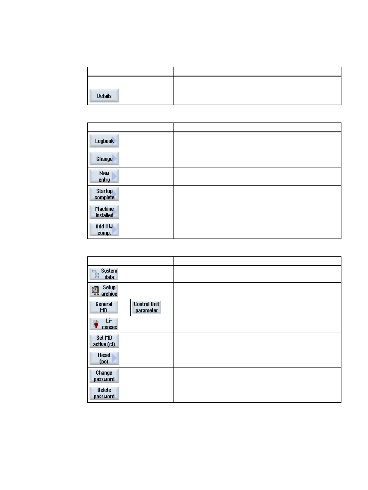
Parameters operating area Protection level
Tool management lists
Keyswitch 3
(protection level 4)
Diagnostics operating area Protection level
Keyswitch 3
(protection level 4)
User
(protection level 3)
User
(protection level 3)
Manufacturer
(protection level 1)
Introduction
2.4 User interface
User
(protection level 3)
Service
(protection level 2)
Start-up operating area Protection levels
End user
(protection level 3)
Keyswitch 3
(protection level 4)
Keyswitch 3
(protection level 4)
Keyswitch 3
(protection level 4)
Keyswitch 3
(protection level 4)
End user
(protection level 3)
End user
(protection level 3)
End user
(protection level 3)
Turning
Operating Manual, 06/2019, A5E44903486B AB 65
Page 66
Introduction
2.4 User interface
2.4.15 Cleaning mode
In cleaning mode, you can clean the user interface of the panel without inadvertently initiating
touch functions.
When you activate cleaning mode, the system does not respond when you touch the screen.
Switching over to another panel and entering data at the keyboard are deactivated. The display
is dimmed. The progress bar shows the remaining time in seconds.
Depending on the setting, cleaning mode lasts between 10 seconds and 1 minute. You can
work as usual once this time has expired.
Note
Use a suitable cleaning agent to clean the screen.
Procedure
1. Select the "Start-up" operating area.
2. Press the "Cleaning mode for panel" softkey.
The system switches into cleaning mode.
2.4.16 Display live image from a camera
In SINUMERIK Operate, you can display a live image from a camera.
● The camera image allows you to track remote processes and monitor difficult-to-access
areas.
● You can also document and store machine states.
● You can create and configure up to two cameras.
Machine manufacturer
Please observe the information provided by the machine manufacturer.
You configure the cameras in the "Camera configuration" window, which you call with the
"Camera" softkey in the "Setup" operating area.
Requirement
● The cameras used meet the required criteria for maximum resolution, frame rate,
compression rate and network capability.
● You have configured the cameras used.
Turning
66 Operating Manual, 06/2019, A5E44903486B AB
Page 67

Call live streaming
Introduction
2.4 User interface
You have the following options for calling live streaming:
● By clicking the "Camera" softkey in the "Machine" operating area
● By clicking the "Camera" softkey in the "Set up" operating area
● Via the "Camera 1" and "Camera 2" widgets in the sidescreen
● Via the "Camera 1" and "Camera 2" widgets in the Display Manager (840D sl only)
The live streaming is displayed in the first-called window.
To switch between the calling windows, live streaming must be restarted.
Note
As long as the "Camera configuration" window is open, live streaming can only be started from
this window.
2.4.17 Online help in SINUMERIK Operate
A comprehensive context-sensitive online help is stored in the control system.
● A brief description is provided for each window and, if required, step-by-step instructions for
the operating sequences.
● A detailed help is provided in the editor for every entered G code. You can also display all
G functions and take over a selected command directly from the help into the editor.
● A help page with all parameters is provided on the input screen in the cycle programming.
● Lists of the machine data
● Lists of the setting data
● Lists of the drive parameters
● List of all alarms
Procedure
Calling context-sensitive online help
1. You are in an arbitrary window of an operating area.
2. Press the <HELP> key or on an MF2 keyboard, the <F12> key.
The help page of the currently selected window is opened in a subscreen.
3. Press the "Full screen" softkey to use the entire user interface for the
display of the online help.
Press the "Full screen" softkey again to return to the subscreen.
Turning
Operating Manual, 06/2019, A5E44903486B AB 67
Page 68
Introduction
2.4 User interface
4. If further help is offered for the function or associated topics, position the
cursor on the desired link and press the "Follow reference" softkey.
The selected help page is displayed.
5. Press the "Back to reference" softkey to jump back to the previous help.
Calling a topic in the table of contents
1. Press the "Table of contents" softkey.
Depending on which technology you are using, the Operating Manuals
"Operator control Milling", "Operator control Turning" or "Operator con‐
trol Universal" as well as the "Programming" Programming Manual are
displayed.
2. Select the desired manual with the <Cursor down> and <Cursor up>
keys.
3. Press the <Cursor right> or <INPUT> key or double-click to open the
book and the section.
4. Navigate to the desired topic with the "Cursor down" key.
5. Press the <Follow reference> softkey or the <INPUT> key to display the
help page for the selected topic.
6. Press the "Current topic" softkey to return to the original help.
Searching for a topic
1. Press the "Search" softkey.
The "Search in Help for: " window appears.
2. Activate the "Full text " checkbox to search in all help pages.
If the checkbox is not activated, a search is performed in the table of
contents and in the index.
3. Enter the desired keyword in the "Text" field and press the "OK" softkey.
If you enter the search term on the operator panel, replace an umlaut
(accented character) by an asterisk (*) as dummy.
All entered terms and sentences are sought with an AND operation. In
this way, only documents and entries that satisfy all the search criteria
are displayed.
4. Press the "Keyword index" softkey if you only want to display the index of
the operating and programming manual.
Turning
68 Operating Manual, 06/2019, A5E44903486B AB
Page 69
Displaying alarm descriptions and machine data
1. If messages or alarms are pending in the "Alarms", "Messages" or "Alarm
Log" window, position the cursor at the appropriate display and press
<HELP> or key <F12>
The associated alarm description is displayed.
2. If you are in the "Start-up" operating area in the windows for the display
of the machine, setting and drive data, position the cursor on the desired
machine data or drive parameter and press the <HELP> key or <F12>
key.
The associated data description is displayed.
Displaying and inserting a G code command in the editor
1. A program is opened in the editor.
Position the cursor on the desired G code command and press the
<HELP> or the <F12> key.
The associated G code description is displayed.
2. Press the "Display all G functions" softkey.
Introduction
2.4 User interface
3. With the aid of the search function, select, for example, the desired G
code command.
4. Press the "Transfer to editor" softkey.
The selected G function is taken into the program at the cursor position.
5. Press the "Exit help" softkey again to close the help.
Turning
Operating Manual, 06/2019, A5E44903486B AB 69
Page 70

Introduction
2.4 User interface
Turning
70 Operating Manual, 06/2019, A5E44903486B AB
Page 71

Multitouch operation with SINUMERIK Operate
3.1 Multitouch panels
The "SINUMERIK Operate Generation 2" user interface has been optimized for multitouch
operation. You can execute all actions by touch and finger gestures. Using SINUMERIK
Operate is much quicker with touch operation and finger gestures.
Machine manufacturer
Please observe the information provided by the machine manufacturer.
The following operator panel fronts, handheld devices and SINUMERIK control systems can be
operated with the "SINUMERIK Operate Generation 2" user interface:
● OP 015 black
● OP 019 black
● PPU 290.3
● HT 8
● SIMATIC ITC V3
● SIMATIC IFP
3
● SIMATIC panel IPC
Additional information
You can find more information on the topic of "user interface" at:
● SINUMERIK Operate Commissioning Manual (IM9), 840D sl
● SINUMERIK Operate Commissioning Manual (IH9), 828D
You can find additional information on multitouch panels at:
● Operating components - handheld devices, SINUMERIK 840 D sl (OP 015 black / 019 black)
● PPU and Components Manual, SINUMERIK 828D (PPU 290.3)
Turning
Operating Manual, 06/2019, A5E44903486B AB 71
Page 72

Multitouch operation with SINUMERIK Operate
3.2 Touch-sensitive user interface
3.2 Touch-sensitive user interface
When using touch panels, wear thin gloves made of cotton or gloves for touch-sensitive glass
user interfaces with capacitive touch function.
If you are using somewhat thicker gloves, then exert somewhat more pressure when using the
touch panel.
Compatible gloves
You will operate the touch-sensitive glass user interface on the Operator panel optimally with
the following gloves.
● Dermatril L
● Camatril Velours type 730
● Uvex Profas Profi ENB 20A
● Camapur Comfort Antistatic type 625
● Carex type 1505 / k (leather)
● Reusable gloves, medium, white, cotton: BM Polyco (RS order number 562-952)
Thicker work gloves
● Thermoplus KCL type 955
● KCL Men at Work type 301
● Camapur Comfort type 619
● Comasec PU (4342)
Turning
72 Operating Manual, 06/2019, A5E44903486B AB
Page 73
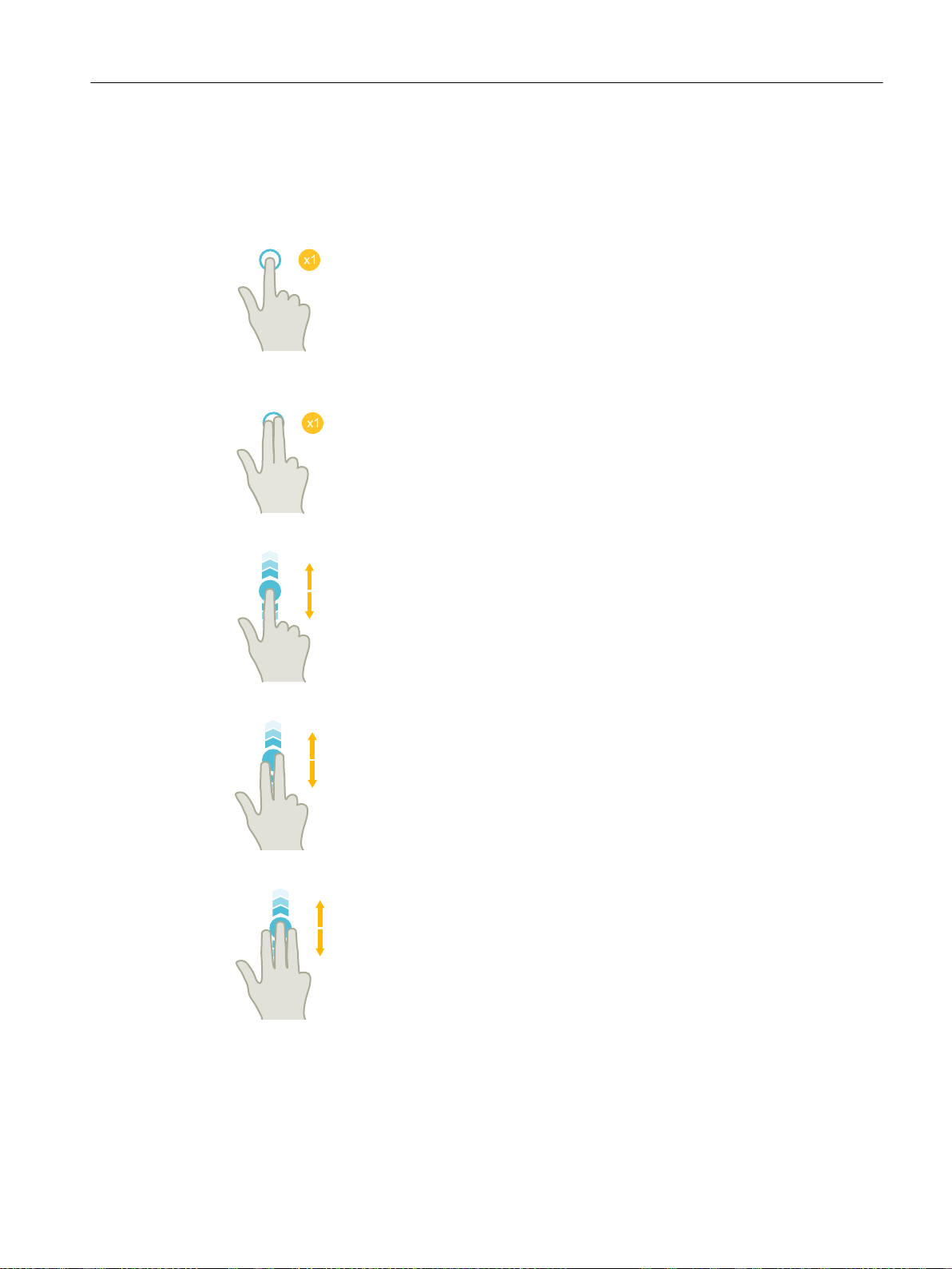
3.3 Finger gestures
Finger gestures
Multitouch operation with SINUMERIK Operate
3.3 Finger gestures
Tap
● Select window
● Select object (e.g. NC set)
● Activate entry field
– Enter or overwrite value
– Tap again to change the value
Tap with 2 fingers
● Call the shortcut menu (e.g. copy, paste)
Flick vertically with one finger
● Scroll in lists (e.g. programs, tools, zero points)
● Scroll in files (e.g. NC program)
Flick vertically with two fingers
Flick vertically with three fingers
● Page-scroll in lists (e.g. ZO)
● Page-scroll in files (e.g. NC programs)
● Scroll to the start or end of lists
● Scroll to the start or end of files
Turning
Operating Manual, 06/2019, A5E44903486B AB 73
Page 74

Multitouch operation with SINUMERIK Operate
3.3 Finger gestures
Flick horizontally with one finger
Spread
Pinch
● Scroll in lists with many columns
● Zoom in on graphic contents (e.g. simulation, mold
making view)
● Zoom out from graphic contents (e.g. simulation, mold
making view)
Pan with one finger
Pan with two fingers
Tap and hold
● Move graphic contents (e.g. simulation, mold making
view)
● Move list contents
● Rotate graphic contents (e.g. simulation, mold making
view)
● Open input fields to change
● Activate or deactivate edit mode (e.g. current block
display)
Turning
74 Operating Manual, 06/2019, A5E44903486B AB
Page 75

Multitouch operation with SINUMERIK Operate
3.3 Finger gestures
Tap and hold using 2 fingers
● Open cycles line by line to change (without input screen
form)
Tapping with 2 index fingers – only for 840D sl
● Tap with two fingers simultaneously in the lower right- and
left-hand corners to open the TCU menu.
The menu has to be opened for service purposes.
Note
Flicking gestures with several fingers
The gestures only function reliably if you hold your fingers sufficiently far apart. The fingers
should be at least 1 cm apart.
Turning
Operating Manual, 06/2019, A5E44903486B AB 75
Page 76
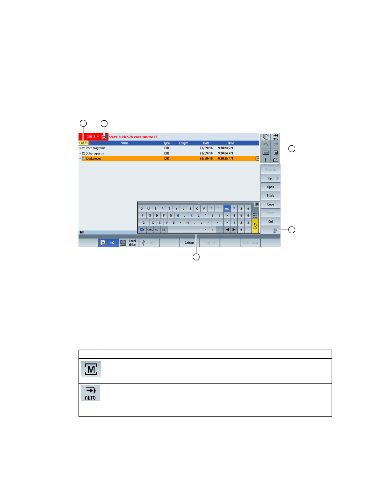
Multitouch operation with SINUMERIK Operate
3.4 Multitouch user interface
3.4 Multitouch user interface
3.4.1 Screen layout
Touch and gesture operator controls for SINUMERIK Operate with the "SINUMERIK Operate
Generation 2" user interface.
① Changing the channel
② Cancel alarms
③ Function key block
④ Display next vertical softkey bar
⑤ Virtual keyboard
3.4.2 Function key block
Operator control Function
Switch operating area
Tap the current operating area, and select the desired operating area from the
operating area bar.
Switch operating mode
The operating mode is only displayed.
To switch the operating mode, tap the operating area and select the operating
area from the vertical softkey bar.
Turning
76 Operating Manual, 06/2019, A5E44903486B AB
Page 77
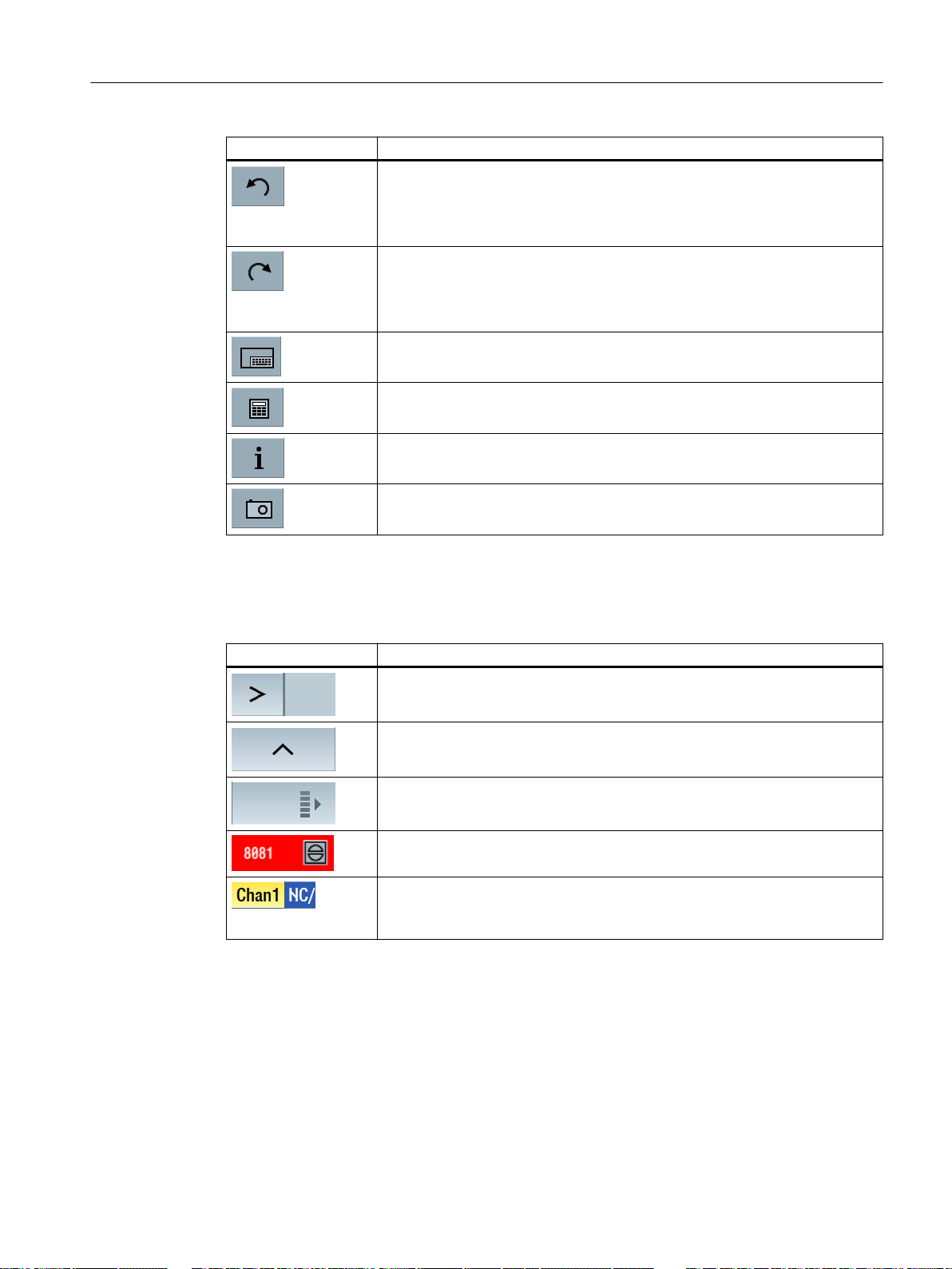
Operator control Function
Undo
Multiple changes are undone one by one.
As soon as a change has been completed in an input field, this function is no
longer available.
Restoring
Multiple changes are restored one by one.
As soon as a change has been completed in an input field, this function is no
longer available.
Virtual keyboard
Activates the virtual keyboard.
Calculator
Displays a calculator.
Online help
Opens the online help.
Camera
Generates a screenshot.
Multitouch operation with SINUMERIK Operate
3.4 Multitouch user interface
3.4.3 Further operator touch controls
Operator control Function
Advances to the next horizontal softkey bar.
When page 2 of the menu is called, the arrow appears on the right.
Advances to the higher-level menu.
Advances to the next vertical softkey bar.
Tapping the Cancel alarm symbol clears all queued cancel alarms.
If a channel menu has been configured, it is displayed.
Tapping the channel display in the status display switches you to the next
channel.
Turning
Operating Manual, 06/2019, A5E44903486B AB 77
Page 78
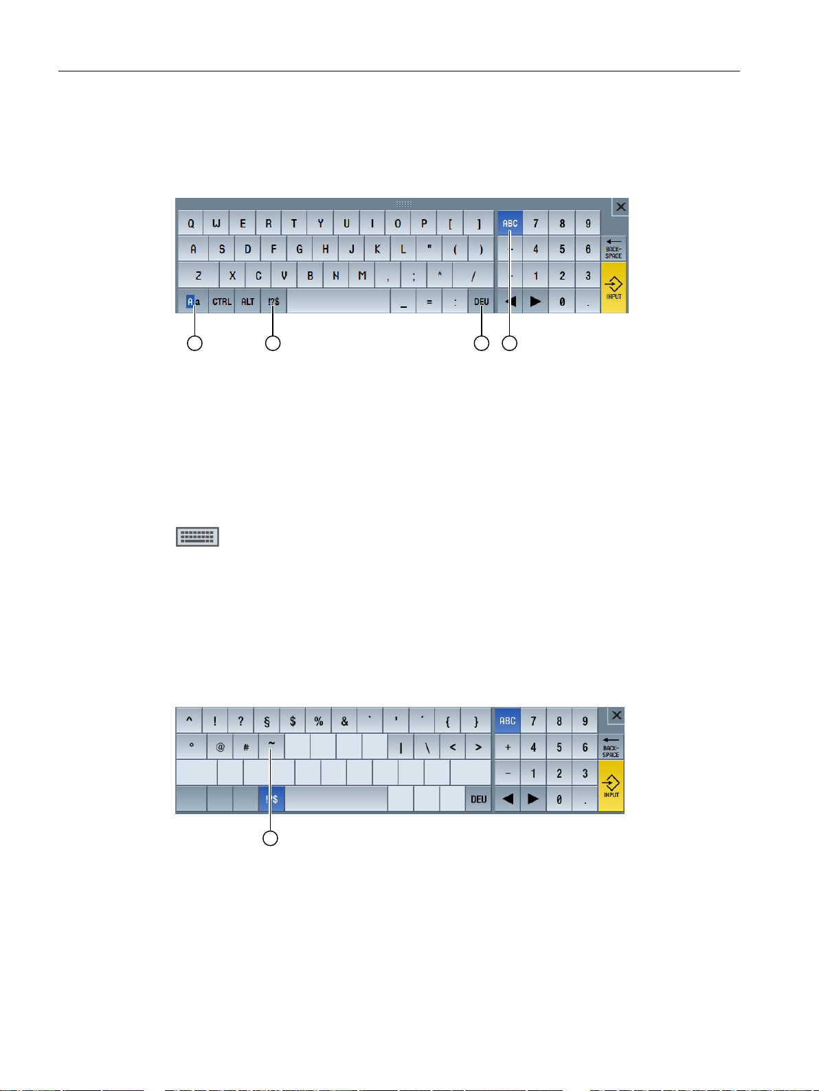
Multitouch operation with SINUMERIK Operate
3.4 Multitouch user interface
3.4.4 Virtual keyboard
If you called the virtual keyboard using the function key block, then you have the option of
adapting the key assignment using the shift keys.
① Shift key for uppercase and lowercase letters
② Shift key for letters and special characters
③ Shift key for country-specific keyboard assignment
④ Shift key for full keyboard and numerical key block
Hardware keyboard
If a real keyboard is connected, the icon of a minimized keyboard appears in place of the virtual
keyboard.
Use the icon to open the virtual keyboard again.
3.4.5 Special "tilde" character
If the shift key for letters and special characters is pressed, the keyboard assignment changes
to the special characters.
① <Tilde>
In the Editor or in alphanumeric input fields, the special character <Tilde> is entered with the
<Tilde> key. In numerical input fields, the <Tilde> key changes the sign of a number between
plus and minus.
Turning
78 Operating Manual, 06/2019, A5E44903486B AB
Page 79

3.5 Expansion with side screen
3.5.1 Overview
Panels in widescreen format provide the possibility of using the extra area to display additional
elements. In addition to the SINUMERIK Operate screen, displays and virtual keys are shown
to provide faster information and operation.
This sidescreen must be activated. To do this, a navigation bar is displayed.
You can display the following elements above the navigation bar:
● Displaying (widgets)
● Virtual keys (pages)
– ABC keyboard
– MCP keys
Machine manufacturer
Please observe the information provided by the machine manufacturer.
Multitouch operation with SINUMERIK Operate
3.5 Expansion with side screen
Requirements
● A widescreen format multitouch panel (e.g. OP 015 black) is required to display widgets and
pages.
● It is only possible to activate and configure a sidescreen when using the "SINUMERIK
Operate Generation 2" user interface.
References
For information on activating the sidescreen and to configure the virtual keys, refer to the
following literature:
● SINUMERIK Operate (IM9) / SINUMERIK 840D sl Commissioning Manual
3.5.2 Sidescreen with standard windows
When the sidescreen is activated, a navigation bar is shown on the left-hand side of the user
interface.
This navigation bar can be used to switch directly to the desired operating area, and to show
and hide the sidescreen.
Turning
Operating Manual, 06/2019, A5E44903486B AB 79
Page 80
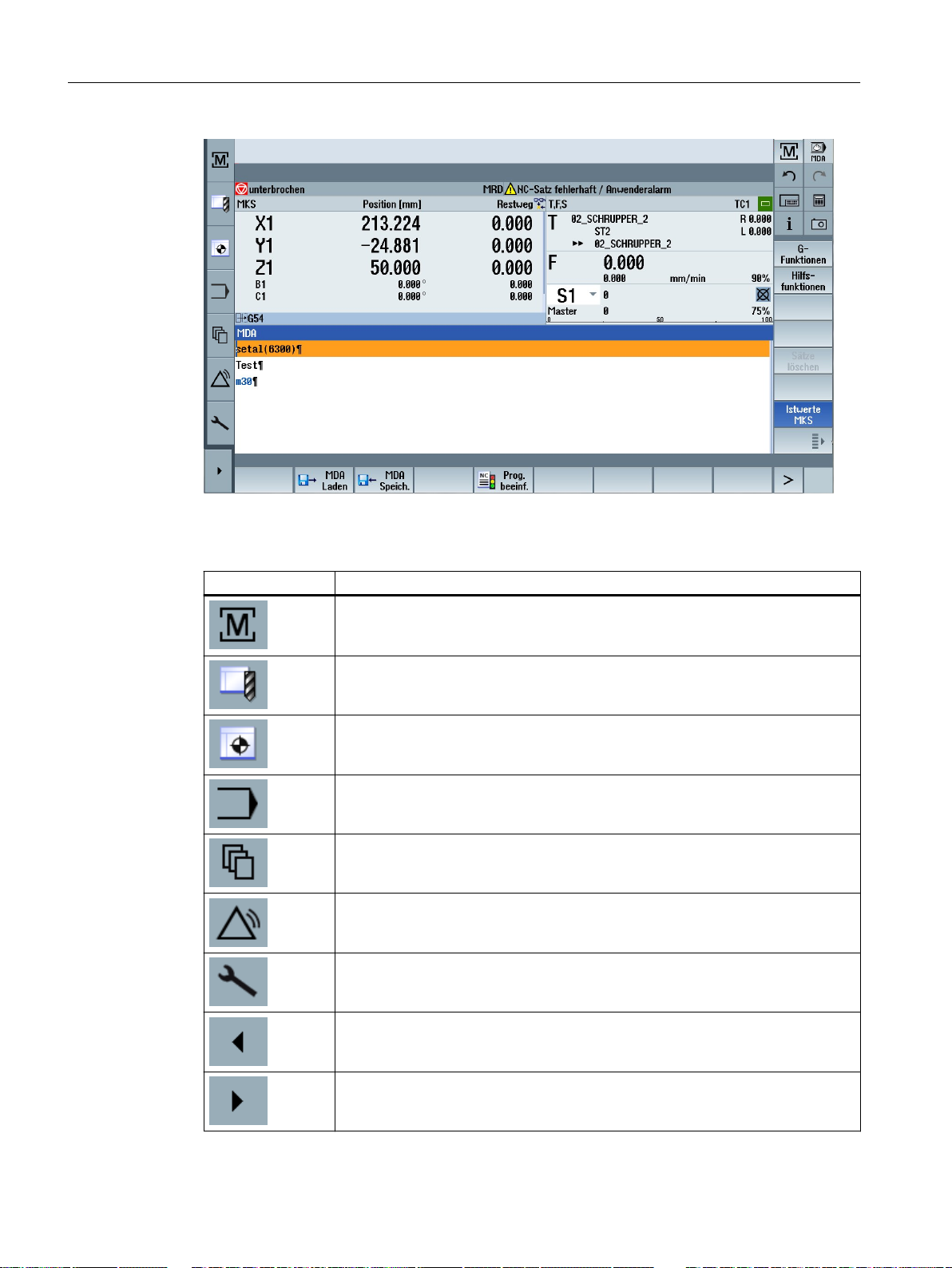
Multitouch operation with SINUMERIK Operate
3.5 Expansion with side screen
Navigation bar
Operator control Function
Opens the "Machinery" operating area.
Opens the tool list in the "Parameter" operating area.
Opens the "Work offset" window in the "Parameter" operating area.
Opens the "Program" operating area.
Opens the "Program manager" operating area.
Opens the "Diagnostics" operating area.
Opens the "Commissioning" operating area.
Hides the sidescreen.
Shows the sidescreen.
Turning
80 Operating Manual, 06/2019, A5E44903486B AB
Page 81
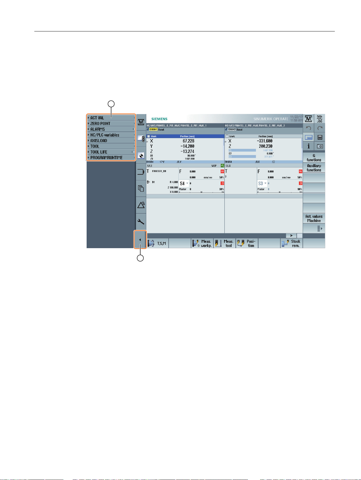
3.5.3 Standard widgets
Open sidescreen
● Tap the arrow on the navigation bar to show the sidescreen.
The standard widgets are displayed in minimized form as the header line.
Multitouch operation with SINUMERIK Operate
3.5 Expansion with side screen
① Widget header lines
② Arrow key for showing/hiding the sidescreen
Navigating in sidescreen
● To scroll through the list of widgets, swipe vertically with 1 finger.
- OR -
● To return to the end or to the beginning of the list of widgets, swipe vertically with 3 fingers.
Open widgets
● To open a widget, tap the header line of the widget.
3.5.4 "Actual value" widget
The widget contains the position of the axes in the displayed coordinate system.
The distance-to-go for the current NC block is displayed while a program is running.
Turning
Operating Manual, 06/2019, A5E44903486B AB 81
Page 82
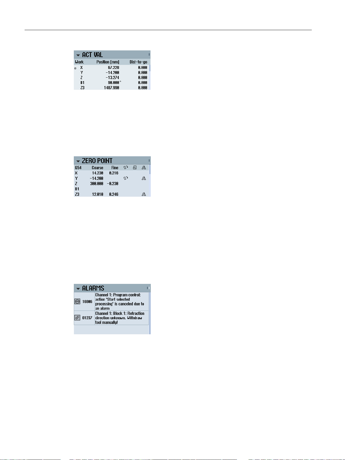
Multitouch operation with SINUMERIK Operate
3.5 Expansion with side screen
3.5.5 "Zero point" widget
The widget includes values of the active work offset for all configured axes.
The approximate and detailed offset, as well as rotation, scaling and mirroring are displayed for
each axis.
3.5.6 "Alarms" widget
The widget contains all the messages and alarms in the alarm list.
The alarm number and description are displayed for every alarm. An acknowledgment symbol
indicates how the alarm is acknowledged or canceled.
Vertical scrolling is possible if multiple alarms are pending.
Wipe horizontally to switch between alarms and messages.
3.5.7 "NC/PLC variables" widget
The "NC/PLC variables" widget displays the NC and PLC variables.
The variable name, data type and value are shown for each variable.
Turning
82 Operating Manual, 06/2019, A5E44903486B AB
Page 83
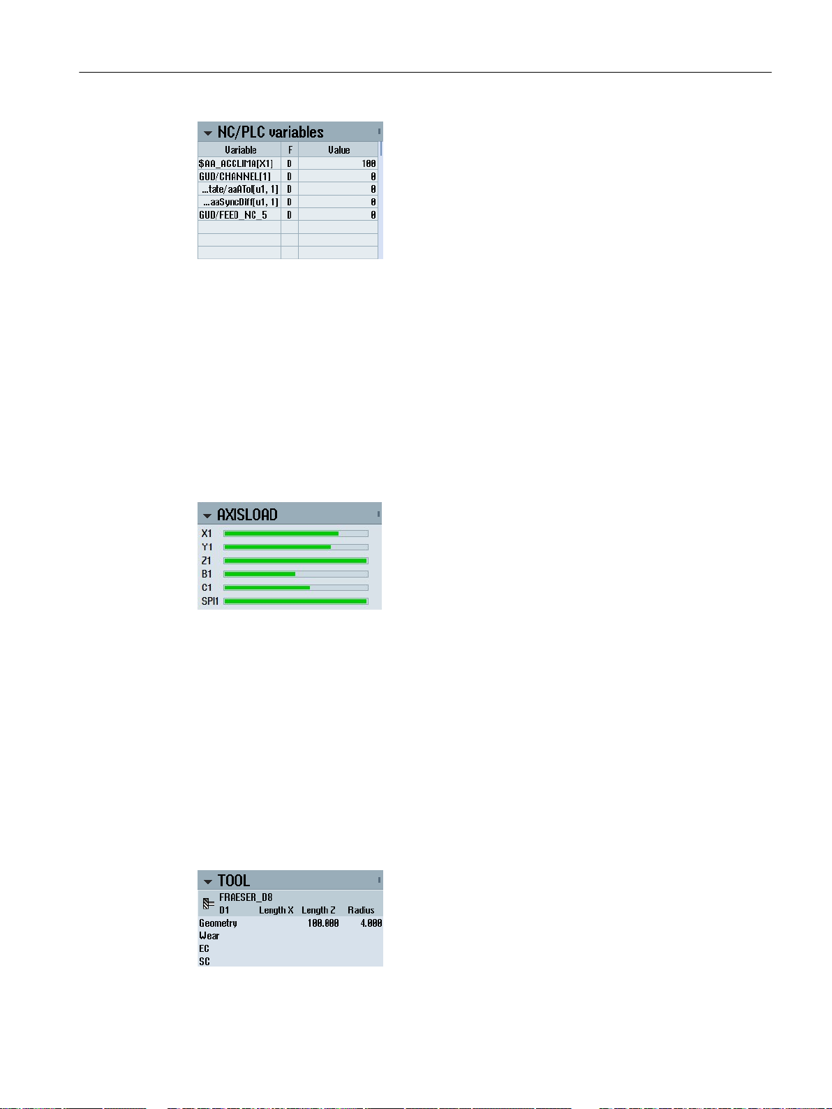
Only those variables that are currently displayed in the "NC/PLC variables" screen in the
"Diagnostics" operating area are shown. To update the list in the "NC/PLC variables" widget
following a change in the "NC/PLC variables" screen in the "Diagnostics" operating area,
collapse and expand the widget again.
Vertical scrolling is possible.
3.5.8 "Axle load" widget
The widget shows the load on all axles in a bar chart.
Multitouch operation with SINUMERIK Operate
3.5 Expansion with side screen
Up to 6 axes are displayed. Vertical scrolling is possible if multiple axes are present.
3.5.9 "Tool" widget
The widget contains the geometry and wear data for the active tool.
The following information is additionally displayed depending on the machine configuration:
● EC: Active location-dependent offset - setting up offset
● SC: Active location-dependent offset - additive offset
● TOFF: Programmed tool length offset in WCS coordinates, and programmed tool radius
offset
● Override: Value of the overridden movements that were made in the individual tool directions
Turning
Operating Manual, 06/2019, A5E44903486B AB 83
Page 84
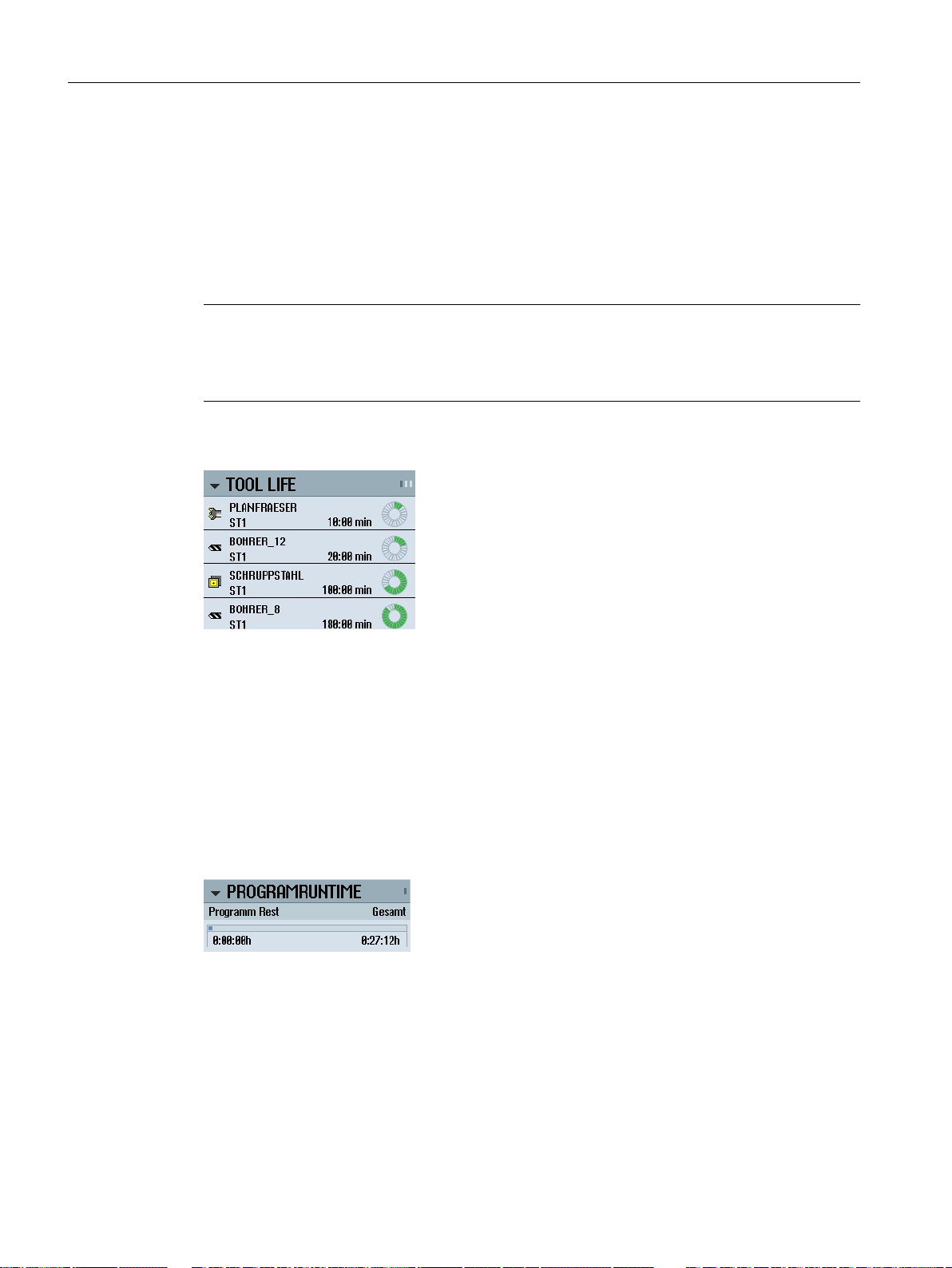
Multitouch operation with SINUMERIK Operate
3.5 Expansion with side screen
3.5.10 "Service life" widget
The widget displays the tool monitoring in relation to the following values:
● Operating time of tool (standard time monitoring)
● Finished workpieces (quantity monitoring)
● Tool wear (wear monitoring)
Note
Multiple cutting edges
If a tool has multiple cutting edges, the values of the edge with the lowest residual service life,
quantity and wear is displayed.
It possible to alternate between views by scrolling horizontally.
3.5.11 "Program runtime" widget
The widget contains the following data:
● Total runtime of the program
● Time remaining to end of program
This data is estimated for the first program run.
Additionally, progress of the program is visualized in a bar chart as a percentage.
3.5.12 Widget "Camera 1" and "Camera 2"
You can create up to two cameras for tracking remote processes and monitoring difficult-toaccess areas.
Widgets "Camera 1" and "Camera 2" are used to display camera images. There is a dedicated
widget for each camera.
Turning
84 Operating Manual, 06/2019, A5E44903486B AB
Page 85
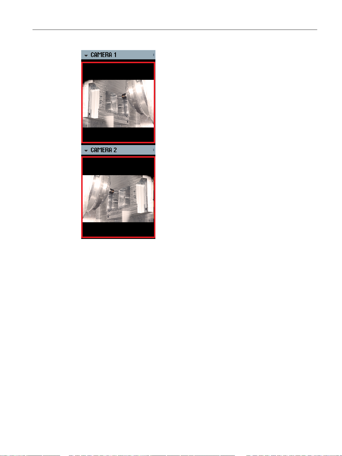
Multitouch operation with SINUMERIK Operate
3.5 Expansion with side screen
If the particular camera has been configured, start streaming by opening the widget.
Additional information on activating widgets "Camera 1" and "Camera 2" is provided in the
SINUMERIK Operate Commissioning Manual.
3.5.13 Sidescreen with pages for the ABC keyboard and/or machine control panel
Not only standard widgets but also pages with ABC keyboards and machine control panels can
be configured in the sidescreen of a multitouch panel.
Turning
Operating Manual, 06/2019, A5E44903486B AB 85
Page 86
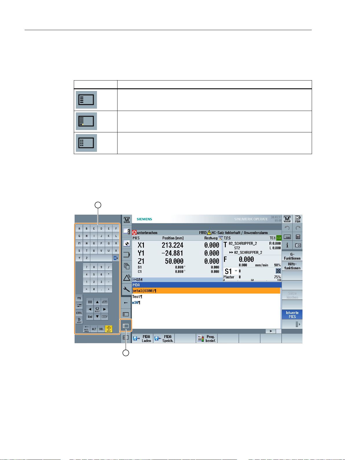
Multitouch operation with SINUMERIK Operate
3.5 Expansion with side screen
Configure ABC keyboard and MCP
If you configured ABC keyboard and MCP keys, then the navigation bar is extended for the
sidescreen:
Operator control Function
Display of standard widgets in the sidescreen
Display of an ABC keyboard on the sidescreen
Display of a machine control panel on the sidescreen
3.5.14 Example 1: ABC keyboard in the sidescreen
① ABC keyboard
② Key to display the keyboard
Turning
86 Operating Manual, 06/2019, A5E44903486B AB
Page 87
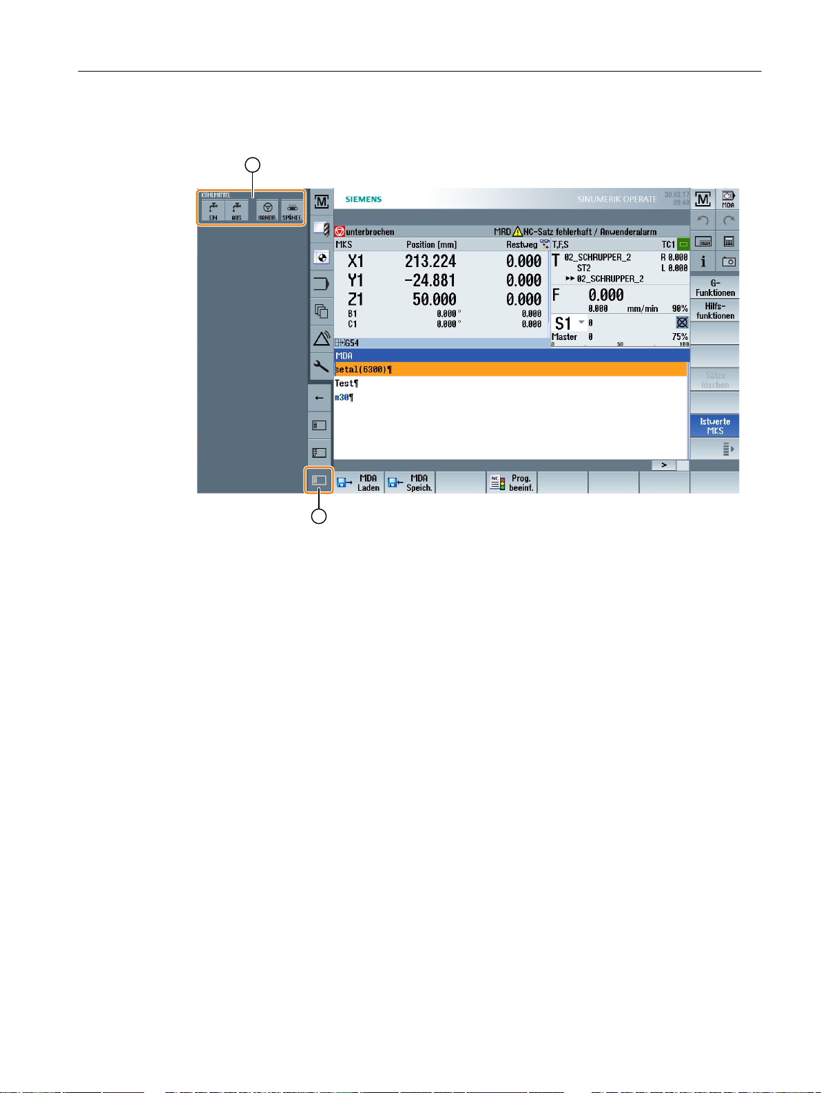
Multitouch operation with SINUMERIK Operate
3.5.15 Example 2: Machine control panel in the sidescreen
3.5 Expansion with side screen
① Machine control panel
② Key to display the machine control panel
Turning
Operating Manual, 06/2019, A5E44903486B AB 87
Page 88

Multitouch operation with SINUMERIK Operate
3.6 SINUMERIK Operate Display Manager (840D sl only)
3.6 SINUMERIK Operate Display Manager (840D sl only)
3.6.1 Overview
With a panel with full HD resolution (1920x1080), you have the possibility to work with the
Display Manager.
The Display Manager allows you to see a lot of information at a glance.
With the Display Manager, the screen area is divided into several display areas.
In addition to SINUMERIK Operate, widgets, keyboards, a machine control panel and various
applications are provided in the various areas.
Software option
The option "P81 – SINUMERIK Operate Display Manager" is required for the "SINUMERIK
Operate Display Manager" function.
Note
The standard configuration of the Display Manager only supports the landscape orientation of
the screen.
Additional information
For further information on the activation and configuration of the Display Manager, please refer
to the following reference:
● SINUMERIK Operate (IM9) / SINUMERIK 840D sl Commissioning Manual
For further information on Full HD Panels, please refer to:
● Operator panel fronts manual: TOP 1500, TOP 1900, TOP 2200 / SINUMERIK 840D sl
Turning
88 Operating Manual, 06/2019, A5E44903486B AB
Page 89
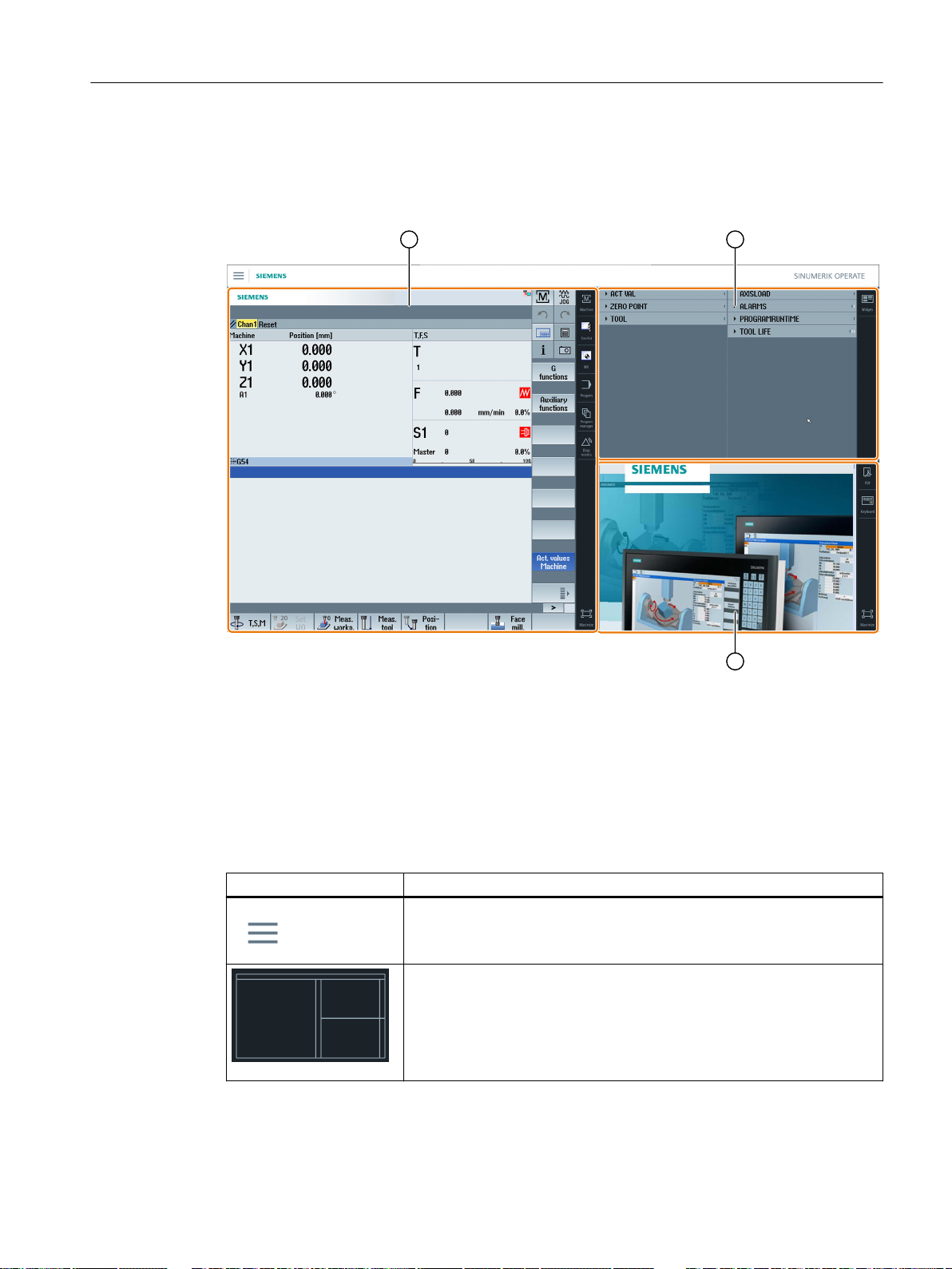
3.6.2 Screen layout
The standard supply of a SINUMERIK Operate Display Manager offers the option of choosing
between 3-display areas and 4-display areas.
Multitouch operation with SINUMERIK Operate
3.6 SINUMERIK Operate Display Manager (840D sl only)
① SINUMERIK Operate with navigation bar for switchover of the operating area
② Display area for standard widgets
③ Display area for applications (e.g. PDF)
3.6.3 Operator controls
The Display Manager is activated.
Operator control Function
Menu
Tap on the menu to select the desired arrangement of the display areas.
3-display areas
● SINUMERIK Operate (with function block)
● Widget area
● Applications area (PDF, virtual keyboard)
Turning
Operating Manual, 06/2019, A5E44903486B AB 89
Page 90
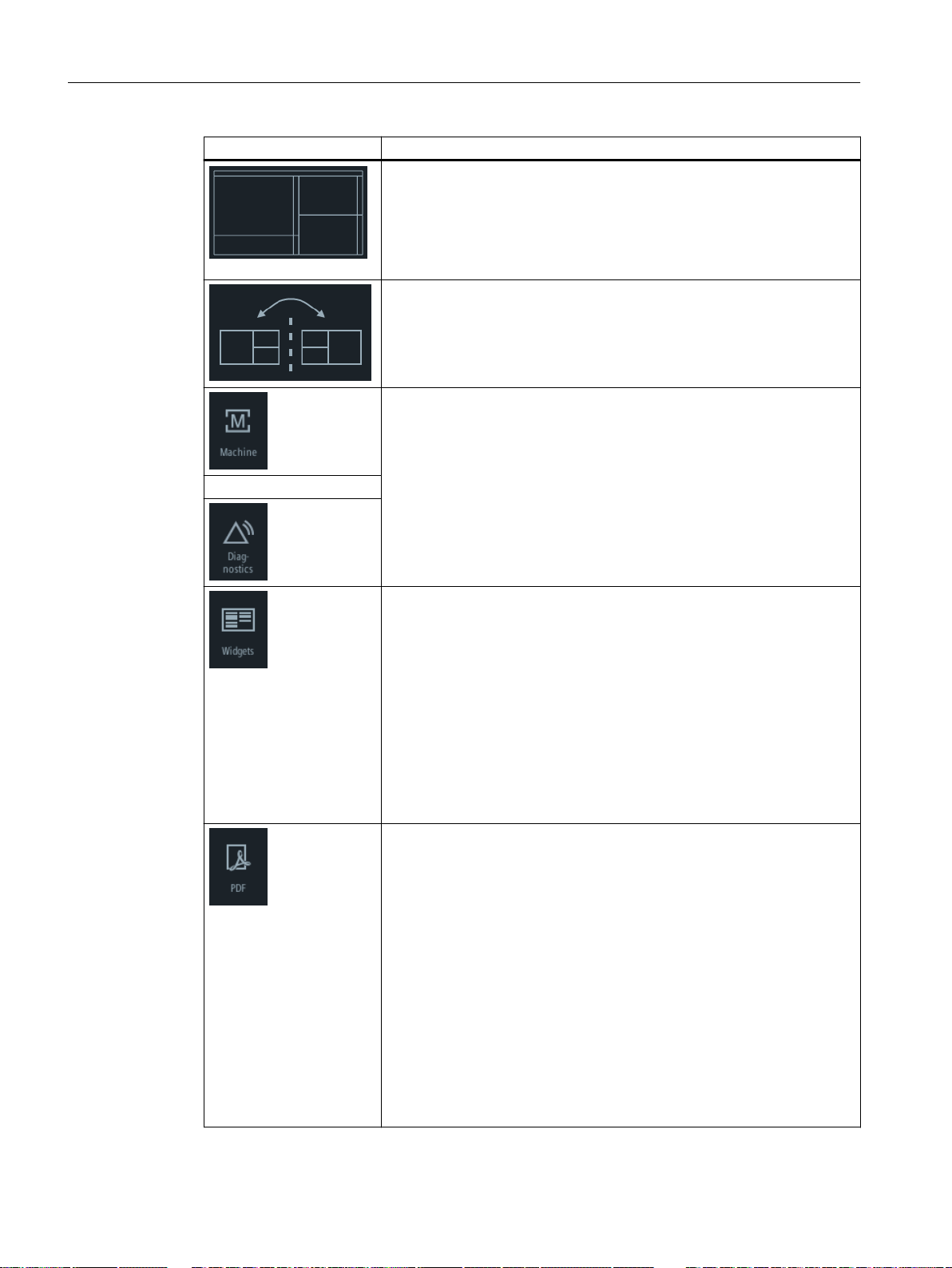
Multitouch operation with SINUMERIK Operate
3.6 SINUMERIK Operate Display Manager (840D sl only)
Operator control Function
4-display areas
● SINUMERIK Operate (with function block)
● Widget area
● Applications area (PDF, virtual keyboard)
● Area with virtual keyboard
Mirroring display areas
Mirrors the selected arrangement of the display areas.
Navigating in SINUMERIK Operate
Tap on the corresponding icon to directly open the desired operating area.
...
Widgets
The following widgets are available by default:
● Actual values (Page 81)
● Zero point (Page 82)
● Tool (Page 83)
● Axle load (Page 83)
● Alarms (Page 82)
● Program runtime (Page 84)
● Service life (Page 84)
● NC/PLC variables (Page 82)
PDF
Opens the PDF stored here.
The following functions are available in the PDF display:
● Open (<CTRL> + <O>)
● Mark (<CTRL> + <A>)
● Copy (<CTRL> + <C>)
● Go to (<CTRL> + <G>)
● Search (<CTRL> + <F>)
● Display and hide bookmarks (<CTRL> + <B>)
Alternatively, use the PDF display via the animated toolbar at the top left.
You optimize the read view using the following finger gestures:
● Double tap: Adapt width:
● <CTRL> + double tap: Adapt height:
Turning
90 Operating Manual, 06/2019, A5E44903486B AB
Page 91
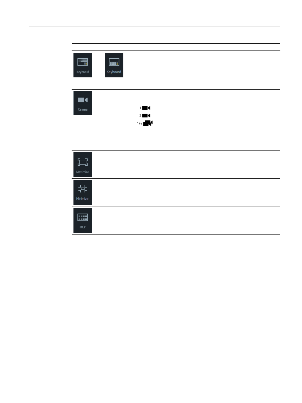
Operator control Function
Virtual keyboard
Displays a QWERTY keyboard in the display area for applications as well
as in the 4th display area below SINUMERIK Operate.
If the virtual keyboard is selected while the display area is maximized, the
keyboard opens as a pop-up. The keyboard can be moved on the display
as required by means of touch operation.
Camera
Live streaming of the configured camera:
● Live streaming camera 1
● Live streaming camera 2
● Live streaming camera 1 and camera 2
If a camera has been configured, you can directly view the relevant stream‐
ing process. If a camera configuration is changed or an issue with connec‐
tivity occurs, reboot the system to activate the streaming process on the
camera.
Maximizing the display area
Enlarges the area with SINUMERIK Operate and the area for the applica‐
tions to the full dimensions of the panel.
Minimizing the display area
The area with SINUMERIK Operate and the area for the applications are
reduced back to their original size.
Multitouch operation with SINUMERIK Operate
3.6 SINUMERIK Operate Display Manager (840D sl only)
See also
Machine control panel
Shows a machine control panel.
Note:
Please observe the information provided by the machine manufacturer.
Widget "Camera 1" and "Camera 2" (Page 84)
Turning
Operating Manual, 06/2019, A5E44903486B AB 91
Page 92

Multitouch operation with SINUMERIK Operate
3.6 SINUMERIK Operate Display Manager (840D sl only)
Turning
92 Operating Manual, 06/2019, A5E44903486B AB
Page 93
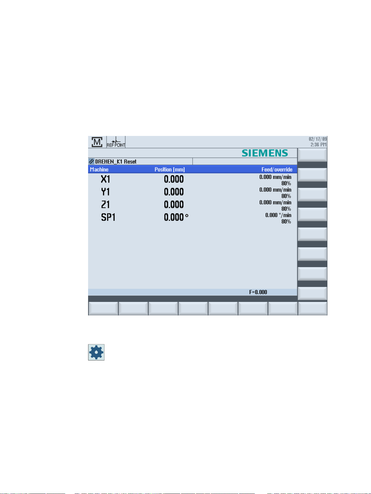
Setting up the machine
4.1 Switching on and switching off
Startup
4
When the control starts up, the main screen opens according to the operating mode specified
by the machine manufacturer. This is usually the main screen for the "REF POINT" function.
Machine manufacturer
Please observe the information provided by the machine manufacturer.
Turning
Operating Manual, 06/2019, A5E44903486B AB 93
Page 94
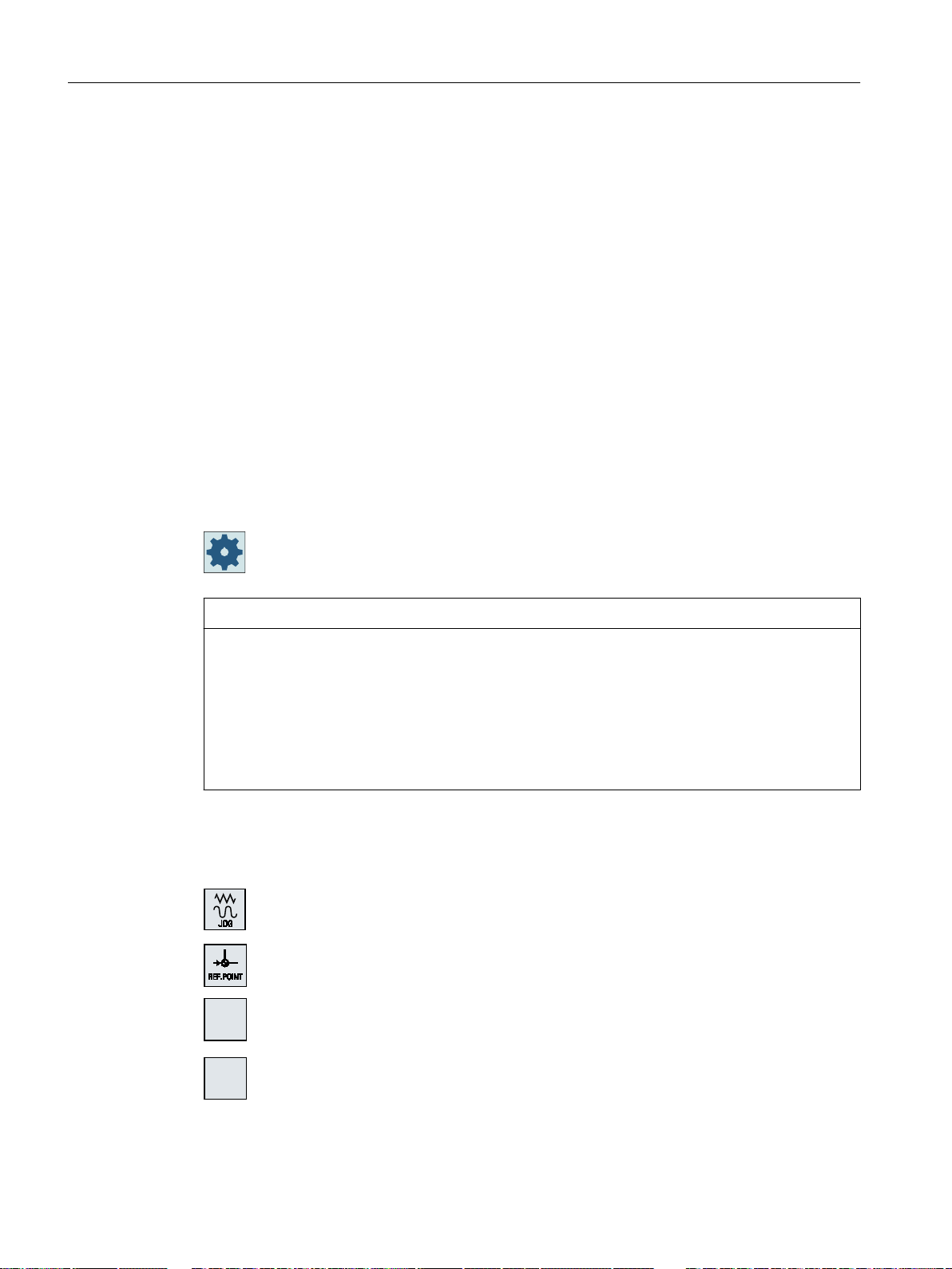
;
=
Setting up the machine
4.2 Approaching a reference point
4.2 Approaching a reference point
4.2.1 Referencing axes
Your machine tool can be equipped with an absolute or incremental path measuring system. An
axis with incremental path measuring system must be referenced after the controller has been
switched on – however, an absolute path measuring system does not have to be referenced.
For the incremental path measuring system, all the machine axes must therefore first approach
a reference point, the coordinates of which are known to be relative to the machine zero-point.
Sequence
Prior to the approach, the axes must be in a position from where they can approach the
reference point without a collision.
The axes can also all approach the reference point simultaneously, depending on the
manufacturer’s settings.
Procedure
Machine manufacturer
Please refer to the machine manufacturer's specifications.
NOTICE
Risk of collision
If the axes are not in a collision-free position, you must first traverse them to safe positions in
"JOG" or "MDI" mode.
You must follow the axis motions directly on the machine!
Ignore the actual value display until the axes have been referenced!
The software limit switches are not active!
1. Press the <JOG> key.
2. Press the <REF. POINT>. key
3. Select the axis to be traversed.
Turning
94 Operating Manual, 06/2019, A5E44903486B AB
Page 95
The axis is referenced as soon as the reference point is reached. The actual value display is set
;
=
to the reference point value.
From now on, path limits, such as software limit switches, are active.
End the function via the machine control panel by selecting operating mode "AUTO" or "JOG".
4.2.2 User agreement
If you are using Safety Integrated (SI) on your machine, you will need to confirm that the current
displayed position of an axis corresponds to its actual position on the machine when you
reference an axis. Your confirmation is the requirement for the availability of other Safety
Integrated functions.
Setting up the machine
4.2 Approaching a reference point
4. Press the <-> or <+> key.
The selected axis moves to the reference point.
If you have pressed the wrong direction key, the action is not accepted
and the axes do not move.
A symbol is shown next to the axis if it has been referenced.
Procedure
You can only give your user agreement for an axis after it has approached the reference point.
The displayed axis position always refers to the machine coordinate system (Machine).
Option
User agreement with Safety Integrated is only possible with a software option.
1. Select the "Machine" operating area.
2. Press the <REF POINT> key.
3. Select the axis to be traversed.
4. Press the <-> or <+> key.
The selected axis moves to the reference point and stops. The coordi‐
nate of the reference point is displayed.
The axis is marked with .
Turning
Operating Manual, 06/2019, A5E44903486B AB 95
Page 96
Setting up the machine
4.2 Approaching a reference point
It shows a list of all machine axes with their current position and SI
6. Position the cursor in the "Acknowledgement" field for the axis in ques‐
The selected axis is marked with an "x" meaning "safely referenced" in
5. Press the "User enable" softkey.
The "User Agreement" window opens.
position.
tion.
7. Activate the acknowledgement with the <SELECT> key.
the "Acknowledgement" column.
By pressing the <SELECT> key again, you deactivate the acknowl‐
edgement again.
Turning
96 Operating Manual, 06/2019, A5E44903486B AB
Page 97
4.3 Modes and mode groups
4.3.1 General
You can work in three different operating modes.
"JOG" mode
"JOG" mode is used for the following preparatory actions:
● Approach reference point, i.e. the machine axis is referenced
● Preparing a machine for executing a program in automatic mode, i.e. measuring tools,
measuring the workpiece and, if necessary, defining the work offsets used in the program
● Traverse axes, e.g. during a program interrupt
● Positioning axes
Setting up the machine
4.3 Modes and mode groups
Select "JOG"
The following functions are available in "JOG" mode:
● "REF POINT"
● "REPOS"
"REF POINT" function
The "REF POINT" function is used to synchronize the control and the machine. For this
purpose, you approach the reference point in "JOG" mode.
Selecting "REF POINT"
"REPOS" function
The "REPOS" function is used for repositioning to a defined position. After a program interrupt
(e.g. to correct tool wear values), move the tool away from the contour in "JOG" mode.
Press the <JOG> key.
Press the <REF POINT> key.
The path differences traversed in "JOG" mode are displayed in the actual value window as the
"REPOS" offset.
"REPOS" offsets can be displayed in the machine coordinate system (MCS) or workpiece
coordinate system (WCS).
Turning
Operating Manual, 06/2019, A5E44903486B AB 97
Page 98
Setting up the machine
4.3 Modes and mode groups
Select "REPOS"
Press the <REPOS> key.
"MDI" mode (Manual Data Input)
In "MDI" mode, you can enter and execute G code commands non-modally to set up the
machine or to perform a single action.
Selecting "MDI"
Press the <MDI> key.
The "TEACH IN" function is available in "MDI" mode.
"TEACH IN" function
With the "TEACH IN" function, you can create, edit and execute part programs (main programs
and subroutines) for motion sequences or simple workpieces by approaching and saving
positions.
Selecting "Teach In"
"AUTO" mode
In automatic mode, you can execute a program completely or only partially.
Select "AUTO"
The "Single block" function is available in "AUTO" mode.
"Single block" function
You can execute a program block-by-block with the "Single block" function.
Press the <TEACH IN> key.
Press the <AUTO> key.
Select "Single block"
Press the <SINGLE BLOCK> key.
Turning
98 Operating Manual, 06/2019, A5E44903486B AB
Page 99

4.3.2 Modes groups and channels
Every channel behaves like an independent NC. A maximum of one part program can be
processed per channel.
● Control with 1channel
One mode group exists.
● Control with several channels
Channels can be grouped to form several "mode groups."
Example
Control with 4 channels, where machining is carried out in 2 channels and 2 other channels are
used to control the transport of the new workpieces.
Mode group 1 channel 1 (machining)
Channel 2 (transport)
Mode group 2 channel 3 (machining)
Channel 4 (transport)
Setting up the machine
4.3 Modes and mode groups
Mode groups (MGs)
Technologically-related channels can be combined to form a mode group.
Axes and spindles of the same mode group can be controlled by one or more channels.
An operating mode group is in one of "Automatic", "JOG" or "MDI" operating modes, i.e.,
several channels of an operating mode group can never assume different operating modes.
4.3.3 Channel switchover
It is possible to switch between channels when several are in use. Since individual channels
may be assigned to different mode groups, a channel switchover command is also an implicit
mode switchover command.
When a channel menu is available, all of the channels are displayed on softkeys and can be
switched over.
Changing the channel
Press the <CHANNEL> key.
The channel changes over to the next channel.
- OR -
If the channel menu is available, a softkey bar is displayed. The active
channel is highlighted.
Another channel can be selected by pressing one of the other softkeys.
Turning
Operating Manual, 06/2019, A5E44903486B AB 99
Page 100

Setting up the machine
4.3 Modes and mode groups
References
SINUMERIK Operate Commissioning Manual
Turning
100 Operating Manual, 06/2019, A5E44903486B AB
 Loading...