

Siemens SINUMERIK 840D sl TCU 30.3 User Manual

SINUMERIK
SINUMERIK 840D sl
TCU 30.3
Valid for: 6FC5312-0DA00-1AA1
Replaces the following products:
TCU.1: 6FC5312-0DA00-0AA0 and
6FC5312-0DA00-0AA1
TCU20.2: 6FC5312-0DA00-0AA2
TCU30.2: 6FC5312-0DA00-1AA0
Fundamental safety
instructions
1
Manual
Description
Mounting
Connection
Networking
Service and maintenance
Technical data
Spare parts / accessories
2
3
4
5
6
7
8
Safety symbols
9
09/2017
A5E40874197
Legal information
Warning notice system
This manual contains notices you have to observe in order to ensure your personal safety, as well as to prevent
damage to property. The notices referring to your personal safety are highlighted in the manual by a safety alert
symbol, notices referring only to property damage have no safety alert symbol. These notices shown below are
graded according to the degree of danger.
DANGER
indicates that death or severe personal injury will result if proper precautions are not taken.
WARNING
indicates that death or severe personal injury may result if proper precautions are not taken.
CAUTION
indicates that minor personal injury can result if proper precautions are not taken.
NOTICE
indicates that property damage can result if proper precautions are not taken.
If more than one degree of danger is present, the warning notice representing the highest degree of danger will be
used. A notice warning of injury to persons with a safety alert symbol may also include a warning relating to property
damage.
Qualified Personnel
The product/system described in this documentation may be operated only by personnel qualified for the specific
task in accordance with the relevant documentation, in particular its warning notices and safety instructions. Qualified
personnel are those who, based on their training and experience, are capable of identifying risks and avoiding
potential hazards when working with these products/systems.
Proper use of Siemens products
Note the following:
WARNING
Siemens products may only be used for the applications described in the catalog and in the relevant technical
documentation. If products and components from other manufacturers are used, these must be recommended or
approved by Siemens. Proper transport, storage, installation, assembly, commissioning, operation and
maintenance are required to ensure that the products operate safely and without any problems. The permissible
ambient conditions must be complied with. The information in the relevant documentation must be observed.
Trademarks
All names identified by ® are registered trademarks of Siemens AG. The remaining trademarks in this publication
may be trademarks whose use by third parties for their own purposes could violate the rights of the owner.
Disclaimer of Liability
We have reviewed the contents of this publication to ensure consistency with the hardware and software described.
Since variance cannot be precluded entirely, we cannot guarantee full consistency. However, the information in
this publication is reviewed regularly and any necessary corrections are included in subsequent editions.
Siemens AG
Division Digital Factory
Postfach 48 48
90026 NÜRNBERG
GERMANY
Document order number: A5E40874197
Ⓟ 08/2017 Subject to change
Copyright © Siemens AG 2007 - 2017.
All rights reserved

Table of contents
1 Fundamental safety instructions...................................................................................................................5
1.1 General safety instructions.......................................................................................................5
1.2 Equipment damage due to electric fields or electrostatic discharge........................................8
1.3 Warranty and liability for application examples........................................................................8
1.4 Industrial security.....................................................................................................................9
1.5 Residual risks of power drive systems...................................................................................10
2 Description..................................................................................................................................................11
2.1 Overview................................................................................................................................11
2.2 Configurations........................................................................................................................12
2.3 Interfaces...............................................................................................................................13
2.4 Rating plate............................................................................................................................17
3 Mounting.....................................................................................................................................................19
3.1 Introduction............................................................................................................................19
3.2 Mounting the TCU on the operator panel front with mounting bracket...................................19
3.3 Mounting the TCU on the operator panel front without mounting bracket..............................23
4 Connection.................................................................................................................................................25
4.1 Pin assignment of the interfaces............................................................................................25
4.1.1 Power supply..........................................................................................................................25
4.1.2 USB interfaces.......................................................................................................................25
4.1.3 Ethernet RJ45 interface.........................................................................................................27
4.1.4 LVDS display interface...........................................................................................................28
4.1.5 Direct key interface................................................................................................................29
5 Networking..................................................................................................................................................33
5.1 System settings......................................................................................................................33
5.1.1 Thin Client Unit (TCU)............................................................................................................33
5.1.2 Settings for SINUMERIK solution line....................................................................................34
5.1.3 System boot with system network..........................................................................................36
5.1.4 Factory default settings..........................................................................................................37
5.2 Commissioning TCU..............................................................................................................39
5.2.1 Key assignment......................................................................................................................39
5.2.2 Settings in the "TCU.ini" file...................................................................................................40
5.2.3 Displacement mechanism for TCUs.......................................................................................41
5.2.4 Disable switchover between TCU via PLC.............................................................................42
5.2.5 Example: How to select the behavior of the TCUs during boot up.........................................44
5.3 Network configuration............................................................................................................45
5.3.1 Permissible network topologies..............................................................................................45
TCU 30.3
Manual, 09/2017, A5E40874197 3

Table of contents
5.3.2 Networks without connection to the company network..........................................................46
5.3.2.1 Configuration 1: NCU and TCU..............................................................................................46
5.3.3 Networks with NCU connection to the company network......................................................47
5.3.3.1 Configuration 2: NCU and TCU..............................................................................................47
5.3.3.2 Configuration 3: PCU with TCU on NCU................................................................................48
5.3.3.3 Connecting the programming device (PG) to the NCU..........................................................49
5.3.4 Example: Configuring a VNC connection to a PC..................................................................49
5.4 Service and diagnostics.........................................................................................................51
5.4.1 Using the TCU's main menu..................................................................................................51
5.4.2 Operating the TCU menu "Service sessions"........................................................................53
5.4.3 Operating the TCU menu "Service menu".............................................................................56
5.4.4 Operating the TCU menu "Modify settings"...........................................................................59
5.4.5 Operating the menu for a new TCU or spare part TCU.........................................................60
5.4.6 How to register a TCU on the system network.......................................................................65
5.4.7 This is how you register a spare part TCU.............................................................................68
5.4.8 Booting of the TCU ...............................................................................................................69
5.4.8.1 Messages during booting.......................................................................................................69
5.4.8.2 Diagnostics options during booting .......................................................................................70
6 Service and maintenance...........................................................................................................................73
7 Technical data............................................................................................................................................75
7.1 Technical data........................................................................................................................75
7.2 Supplementary electrical conditions.......................................................................................76
7.2.1 Power supply..........................................................................................................................76
7.2.2 Grounding concept.................................................................................................................77
7.2.3 RI suppression measures......................................................................................................77
7.2.4 SINUMERIK_SouthKorea_Note.............................................................................................78
7.3 Climatic and mechanical environmental conditions...............................................................79
7.3.1 Transport and storage conditions...........................................................................................79
7.3.2 Operating conditions..............................................................................................................80
7.4 Standards and approvals.......................................................................................................82
7.5 Recycling and disposal..........................................................................................................82
8 Spare parts / accessories...........................................................................................................................83
8.1 Accessories............................................................................................................................83
8.2 Handling membrane connectors............................................................................................83
9 Safety symbols...........................................................................................................................................85
Index...........................................................................................................................................................87
TCU 30.3
4 Manual, 09/2017, A5E40874197
Fundamental safety instructions
1.1 General safety instructions
WARNING
Electric shock and danger to life due to other energy sources
Touching live components can result in death or severe injury.
● Only work on electrical devices when you are qualified for this job.
● Always observe the country-specific safety rules.
Generally, the following six steps apply when establishing safety:
1. Prepare for disconnection. Notify all those who will be affected by the procedure.
2. Isolate the drive system from the power supply and take measures to prevent it being
switched back on again.
3. Wait until the discharge time specified on the warning labels has elapsed.
4. Check that there is no voltage between any of the power connections, and between any
of the power connections and the protective conductor connection.
5. Check whether the existing auxiliary supply circuits are de-energized.
6. Ensure that the motors cannot move.
7. Identify all other dangerous energy sources, e.g. compressed air, hydraulic systems, or
water. Switch the energy sources to a safe state.
8. Check that the correct drive system is completely locked.
1
After you have completed the work, restore the operational readiness in the inverse sequence.
WARNING
Electric shock due to connection to an unsuitable power supply
When equipment is connected to an unsuitable power supply, exposed components may
carry a hazardous voltage that might result in serious injury or death.
● Only use power supplies that provide SELV (Safety Extra Low Voltage) or PELV(Protective Extra Low Voltage) output voltages for all connections and terminals of the
electronics modules.
TCU 30.3
Manual, 09/2017, A5E40874197 5
Fundamental safety instructions
1.1 General safety instructions
WARNING
Electric shock due to equipment damage
Improper handling may cause damage to equipment. For damaged devices, hazardous
voltages can be present at the enclosure or at exposed components; if touched, this can
result in death or severe injury.
● Ensure compliance with the limit values specified in the technical data during transport,
storage and operation.
● Do not use any damaged devices.
WARNING
Electric shock due to unconnected cable shields
Hazardous touch voltages can occur through capacitive cross-coupling due to unconnected
cable shields.
● As a minimum, connect cable shields and the cores of cables that are not used at one end
at the grounded housing potential.
WARNING
Electric shock if there is no ground connection
For missing or incorrectly implemented protective conductor connection for devices with
protection class I, high voltages can be present at open, exposed parts, which when touched,
can result in death or severe injury.
● Ground the device in compliance with the applicable regulations.
WARNING
Spread of fire from built-in devices
In the event of fire outbreak, the enclosures of built-in devices cannot prevent the escape of
fire and smoke. This can result in serious personal injury or property damage.
● Install built-in units in a suitable metal cabinet in such a way that personnel are protected
against fire and smoke, or take other appropriate measures to protect personnel.
● Ensure that smoke can only escape via controlled and monitored paths.
TCU 30.3
6 Manual, 09/2017, A5E40874197
Fundamental safety instructions
1.1 General safety instructions
WARNING
Unexpected movement of machines caused by radio devices or mobile phones
When radio devices or mobile phones with a transmission power > 1 W are used in the
immediate vicinity of components, they may cause the equipment to malfunction.
Malfunctions may impair the functional safety of machines and can therefore put people in
danger or lead to property damage.
● If you come closer than around 2 m to such components, switch off any radios or mobile
phones.
● Use the "SIEMENS Industry Online Support App" only on equipment that has already been
switched off.
WARNING
Fire due to inadequate ventilation clearances
Inadequate ventilation clearances can cause overheating of components with subsequent
fire and smoke. This can cause severe injury or even death. This can also result in increased
downtime and reduced service lives for devices/systems.
● Ensure compliance with the specified minimum clearance as ventilation clearance for the
respective component.
WARNING
Unexpected movement of machines caused by inactive safety functions
Inactive or non-adapted safety functions can trigger unexpected machine movements that
may result in serious injury or death.
● Observe the information in the appropriate product documentation before commissioning.
● Carry out a safety inspection for functions relevant to safety on the entire system, including
all safety-related components.
● Ensure that the safety functions used in your drives and automation tasks are adjusted
and activated through appropriate parameterizing.
● Perform a function test.
● Only put your plant into live operation once you have guaranteed that the functions relevant
to safety are running correctly.
Note
Important safety notices for Safety Integrated functions
If you want to use Safety Integrated functions, you must observe the safety notices in the Safety
Integrated manuals.
TCU 30.3
Manual, 09/2017, A5E40874197 7

Fundamental safety instructions
1.2 Equipment damage due to electric fields or electrostatic discharge
1.2 Equipment damage due to electric fields or electrostatic discharge
Electrostatic sensitive devices (ESD) are individual components, integrated circuits, modules
or devices that may be damaged by either electric fields or electrostatic discharge.
NOTICE
Equipment damage due to electric fields or electrostatic discharge
Electric fields or electrostatic discharge can cause malfunctions through damaged individual
components, integrated circuits, modules or devices.
● Only pack, store, transport and send electronic components, modules or devices in their
original packaging or in other suitable materials, e.g conductive foam rubber of aluminum
foil.
● Only touch components, modules and devices when you are grounded by one of the
following methods:
– Wearing an ESD wrist strap
– Wearing ESD shoes or ESD grounding straps in ESD areas with conductive flooring
● Only place electronic components, modules or devices on conductive surfaces (table with
ESD surface, conductive ESD foam, ESD packaging, ESD transport container).
1.3 Warranty and liability for application examples
The application examples are not binding and do not claim to be complete regarding
configuration, equipment or any eventuality which may arise. The application examples do not
represent specific customer solutions, but are only intended to provide support for typical tasks.
You are responsible for the proper operation of the described products. These application
examples do not relieve you of your responsibility for safe handling when using, installing,
operating and maintaining the equipment.
TCU 30.3
8 Manual, 09/2017, A5E40874197

1.4 Industrial security
Note
Industrial security
Siemens provides products and solutions with industrial security functions that support the
secure operation of plants, systems, machines and networks.
In order to protect plants, systems, machines and networks against cyber threats, it is
necessary to implement – and continuously maintain – a holistic, state-of-the-art industrial
security concept. Siemens products and solutions only represent one component of such a
concept.
The customer is responsible for preventing unauthorized access to its plants, systems,
machines and networks. Systems, machines and components should only be connected to
the enterprise network or the internet if and to the extent necessary and with appropriate
security measures (e.g. use of firewalls and network segmentation) in place.
Additionally, Siemens’ guidance on appropriate security measures should be taken into
account. For more information about industrial security, please visit:
Industrial security (http://www.siemens.com/industrialsecurity).
Fundamental safety instructions
1.4 Industrial security
Siemens’ products and solutions undergo continuous development to make them more secure.
Siemens strongly recommends to apply product updates as soon as available and to always
use the latest product versions. Use of product versions that are no longer supported, and
failure to apply latest updates may increase customer’s exposure to cyber threats.
To stay informed about product updates, subscribe to the Siemens Industrial Security RSS
Feed at:
Industrial security (http://www.siemens.com/industrialsecurity).
WARNING
Unsafe operating states resulting from software manipulation
Software manipulations (e.g. viruses, trojans, malware or worms) can cause unsafe operating
states in your system that may lead to death, serious injury, and property damage.
● Keep the software up to date.
● Incorporate the automation and drive components into a holistic, state-of-the-art industrial
security concept for the installation or machine.
● Make sure that you include all installed products into the holistic industrial security concept.
● Protect files stored on exchangeable storage media from malicious software by with
suitable protection measures, e.g. virus scanners.
TCU 30.3
Manual, 09/2017, A5E40874197 9

Fundamental safety instructions
1.5 Residual risks of power drive systems
1.5 Residual risks of power drive systems
When assessing the machine- or system-related risk in accordance with the respective local
regulations (e.g., EC Machinery Directive), the machine manufacturer or system installer must
take into account the following residual risks emanating from the control and drive components
of a drive system:
1. Unintentional movements of driven machine or system components during commissioning,
operation, maintenance, and repairs caused by, for example,
– Hardware and/or software errors in the sensors, control system, actuators, and cables
and connections
– Response times of the control system and of the drive
– Operation and/or environmental conditions outside the specification
– Condensation/conductive contamination
– Parameterization, programming, cabling, and installation errors
– Use of wireless devices/mobile phones in the immediate vicinity of electronic
components
– External influences/damage
– X-ray, ionizing radiation and cosmic radiation
2. Unusually high temperatures, including open flames, as well as emissions of light, noise,
particles, gases, etc., can occur inside and outside the components under fault conditions
caused by, for example:
– Component failure
– Software errors
– Operation and/or environmental conditions outside the specification
– External influences/damage
3. Hazardous shock voltages caused by, for example:
– Component failure
– Influence during electrostatic charging
– Induction of voltages in moving motors
– Operation and/or environmental conditions outside the specification
– Condensation/conductive contamination
– External influences/damage
4. Electrical, magnetic and electromagnetic fields generated in operation that can pose a risk
to people with a pacemaker, implants or metal replacement joints, etc., if they are too close
5. Release of environmental pollutants or emissions as a result of improper operation of the
system and/or failure to dispose of components safely and correctly
6. Influence of network-connected communication systems, e.g. ripple-control transmitters or
data communication via the network
For more information about the residual risks of the drive system components, see the relevant
sections in the technical user documentation.
TCU 30.3
10 Manual, 09/2017, A5E40874197

Description
2.1 Overview
A Thin Client Unit (TCU) allows the spatial separation between an operator panel (OP) / touch
panel (TP) and the Panel Control Unit (PCU) / Numerical Control Unit (NCU). For this reason,
the user interface is copied to one/several operator panel fronts, each with a TCU.
Validity
The description applies to the following TCU:
Designation Article number
Thin Client Unit 30.3 6FC5312-0DA00-1AA1
Features
● Implementation of flat operator panels through the shallow installation depth and low power
loss.
● Color depth: 32 bits
2
Preconditions
● 640 x 480 to 1280 x 1024 pixels
● Vibration-free mounting of the PCU in the control cabinet.
● Effective operation of larger machines.
● Signal transmission between PCU/NCU and operator panel via Industrial Ethernet
The distance of the components is determined by the maximum distance between two
network nodes / access points (100 m).
● The same operating screen is shown synchronously on all operator panel fronts and can
be operated from all operator panel fronts.
● The operation on an operator panel front connected via TCU has the same access rights
as the operation on an operator panel front connected directly to the PCU.
● The mixed operation of operator panel fronts connected via TCU and an operator panel
front connected directly to the PCU is possible.
● With restrictions to the interfaces (see Section "Operating the menu for a new TCU or
replacement TCU (Page 60)"), the TCU 30.3 is compatible to the previous models and
therefore mixed operation is possible.
● NCU 7x0
● Operator panel fronts:
– OP 010, OP 010C, OP 010S, OP 012, OP015, OP 015A, TP 015A, OP 019
TCU 30.3
Manual, 09/2017, A5E40874197 11

5HTXLUHGPRXQWLQJEUDFNHWV
)RU7&8)&$)$$QRWUHTXLUHGIRU236
$GGLWLRQDO7&8QRWUHTXLUHGIRURSHUDWRUSDQHOIURQWVZLWKLQWHJUDWHG7&8
2SHUDWRUSDQHOIURQW
7&8
,QGXVWULDO(WKHUQHW
1&8
Description
2.2 Configurations
Design
The TCUs are coupled via Ethernet as Thin Clients in a dedicated subnetwork (via DHCP
server on the PCU/NCU) to the PCU/NCU.
Interfaces:
● 4 x USB 2.0 Hi-Speed to connect the mouse, keyboard and USB flash drive
● Ethernet 10/100/1000 Mbit/s
The transmission rate in Ethernet system networks automatically sets itself to the maximum
possible value. 1000 Mbit/s can only be achieved with NCU 7x0.3B PN and PCU 50.5 (if a
PCU is required).
Note
The Ethernet interface has so-called Auto MDI-X functionality. If required, the send and
receive lines of the Ethernet cable are crossed in the PHY. If, however, the partner does
not have "Autocrossover", a crossover cable is required.
Information about third-party software used
This product contains open source software. License information can be obtained via the
shortcut "License files" on your SINUMERIK PCU desktop, or navigate to the SINUMERIK
Operate Readme OSS path "Setup/system data: System CF card/siemens/oss-license" on
your SINUMERIK NCU and read the appropriate OSS file for this device.
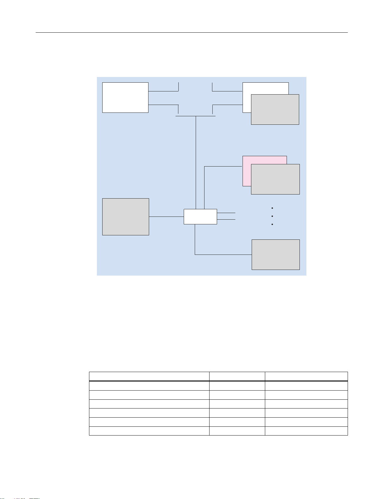
2.2 Configurations
Configurations
The following distributed configurations are possible with a TCU 30.3:
Figure 2-1 Minimum configuration with an operator panel front
12 Manual, 09/2017, A5E40874197
TCU 30.3
2SHUDWRUSDQHO
IURQW
2SHUDWRUSDQHO
IURQW
2SHUDWRUSDQHOIURQW
ZLWKLQWHJUDWHG
7&8
)RUPRXQWLQJRQRSHUDWRUSDQHOIURQW
7&83&8
)&$)$$
QRWUHTXLUHGIRU236
0RXQWLQJEUDFNHWVUHTXLUHG
)RUPRXQWLQJLQFRQWUROFRQWUROFDELQHW
3&8
)&$)$$RU
)&$)$$
,QGXVWULDO
(WKHUQHW
,QGXVWULDO
(WKHUQHW
,QGXVWULDO
(WKHUQHW
,QGXVWULDO(WKHUQHW
3&8
7&8
7&8
3&8
6ZLWFK
1&8[31
Description
2.3 Interfaces
Figure 2-2 Maximum configuration, several TCUs connected to an NCU 7x0
2.3 Interfaces
Overview
For information about TCU commissioning, see the section titled "Networking".
Function Designation Description
Double USB interface 1
Double USB interface 2
Interface for direct keys X205 2 x 10-pin plug connector
24 VDC power supply X206 3-pin terminal block
TCU 30.3
Manual, 09/2017, A5E40874197 13
I/O USB interface K1
LVDS display interface K2
1)
1)
2) 3)
2) 3)
X203 / X204 2 x USB 2.0 Hi-Speed type A
X212 / X213 2 x USB 2.0 Hi-Speed type A
X207 2 x 13-pin plug connector
X208 2 x 10-pin plug connector
Description
2.3 Interfaces
Function Designation Description
LVDS display interface K3
Ethernet interface X202 8-pin RJ45 socket
1)
One of the interfaces can be loaded with 500 mA, the other with 100 mA.
2)
To connect to a 10" to 15" operator panel front
3)
To connect to an OP 019 operator panel front
3)
X209 2 x 10-pin plug connector
The following special requirements apply to the connecting cables:
● The 24 VDC cable must be approved for temperatures up to 70° C.
● Select the permitted conductor cross-section in accordance with the national regulations
(NEC, VDE,...) and the "Power supply connectors for TCU30.3" table below. The line
protection in accordance with the national regulations (NEC, VDE,...) must be guarantied
as appropriate for the selected conductor cross-section.
● Strip the cables (7 mm) for connection to the 24 VDC connector plug.
● Flame resistance of the 24 VDC cable according to UL 2556 VW-1/ tested according to IEC
60332-1-2.
● Observe the permissible bending radii of the cables.
● Rotate the panel only in a way that does not cause pinching of the cables.
● Route all of the cables so that they do not come into contact with chafing edges.
WARNING
Warning for areas subject to NEC or CEC:
Safety notice for connectors with Ethernet marking:
A Ethernet or Ethernet segment, with all its associated interconnected equipment, shall be
entirely contained within a single low-voltage power distribution and within a single building.
The Ethernet is considered to be in an "environment A" according IEEE802.3 or "environment
0" according IEC TR 62102, respectively.
Never make direct electrical connection to TNV-circuits (Telephone Network) or WAN (Wide
Area Network).
TCU 30.3
14 Manual, 09/2017, A5E40874197
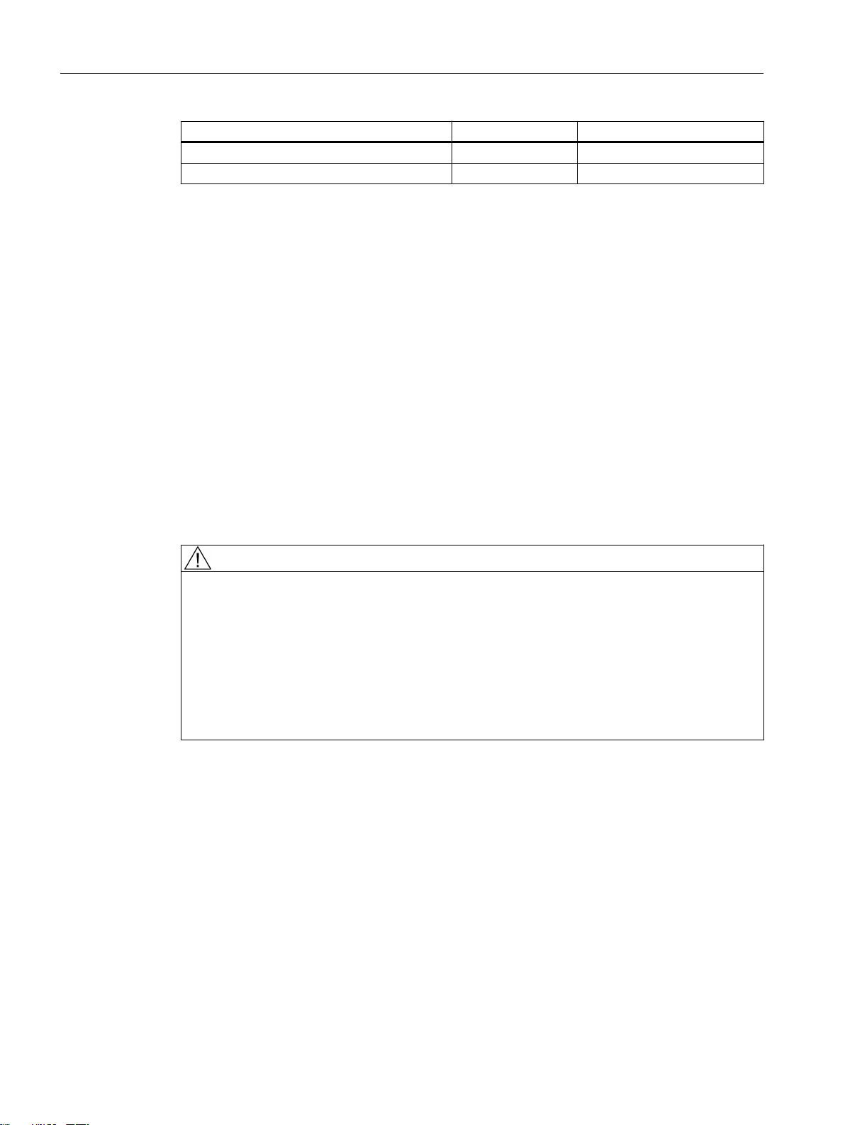
View
9
9
Description
2.3 Interfaces
① X203/X204 Double USB interface 1
② X212/X213 Double USB interface 2
③ X202 Ethernet interface
④ X205 Interface for direct keys
⑤ X206 24 VDC power supply
⑥ - Protective conductor connection
Figure 2-3 Front view of the TCU 30.3 with interfaces
TCU 30.3
Manual, 09/2017, A5E40874197 15
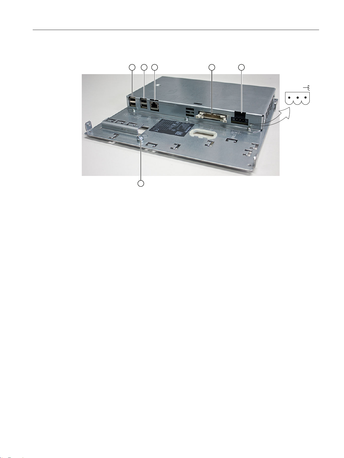
Description
2.3 Interfaces
⑦ X207 I/O USB interface K1
⑧ X208 LVDS display interface K2
⑨ X209 LVDS display interface K3 (not for TCU 20.2)
Figure 2-4 Rear view of the TCU 30.3 with interfaces
The K1, K2, K3 interfaces are suitable only for connecting operator panel fronts OP 010, OP
010S, OP 010C, OP 012, OP 015, OP 015A, TP 015A and OP 019.
Power supply connector for the TCU30.3
Connection type Strain-relief clamp connection
Connection screw M2.5 screw with cross-slot
Operating tool Screwdriver blade 0.6x3.5, PH0, PZ0 (DIN
Prescribed tightening torque Nm 0.4 ... 0.5
Conductor cross-section min./max.
Solid mm² 1.3 … 3.3
Finely stranded mm² 1.3 … 3.3
With end sleeve with sleeve DIN46228/4 mm² 1.3 … 2.5
With end sleeve DIN46228/1 mm² 1.3 … 3.3
AWG cables, solid or stranded AWG 12 … 16
Pin assignment
5264, ISO 8764/2-PH, ISO 8764/2-PZ)
The pin assignments of the interfaces are described in Section "Connect" > "Pin assignment
of the interfaces" (Page 25).
16 Manual, 09/2017, A5E40874197
TCU 30.3
2.4 Rating plate
s
SINUMERIK Bedientafelfront
A5E35520880
Made in Germany
Siemens AG, Frauenauracher Str. 80, DE-91056 Erlangen
TCU 30.3 (thin client unit)
S
2,9ATa 0...55°C SUPPLY 24V
6FC5312-0DA00-1AA11P
T-HD6000297
FS: A
KCC-REM-S49-
2,0 kg
SINUMERIK
00-1F-F8-29-ED-0C
Protection:
http://support.automation.siemens.com
refer to user manual
0,5ADigital Output 24V
Description
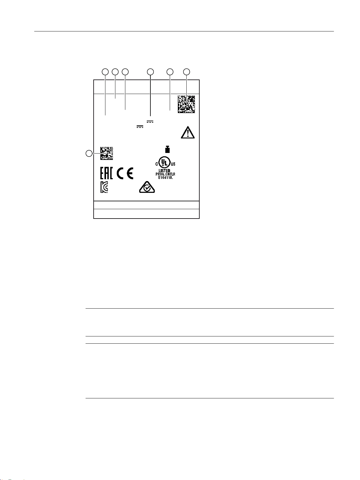
2.4 Rating plate
① Material number
② Component name
③ Article number
④ Serial number
⑤ Hardware revision level
⑥ Product code
⑦ MAC address
Figure 2-5 Example graphic of a TCU30.3 rating plate
Note
The contents of the individual rating plate fields on the front of the TCU may differ from those
described in this manual (e.g. new product version, approvals and markings not yet issued).
Note
Product code scanning
The product code contains the article number of the device. Scan the product code with the
aid of the Siemens Industry Online Support App to be taken directly to the Internet Webpage
for the product, including all of the technical information and graphical data.
The app is available for iPhone, iPad, Android and Windows Phone.
TCU 30.3
Manual, 09/2017, A5E40874197 17

Description
2.4 Rating plate
TCU 30.3
18 Manual, 09/2017, A5E40874197
Mounting
3.1 Introduction
Before assembling the two components, the interface cables of the operator panel front (IO/
USB cable K1, K2 display cable and, if necessary, K3) must be inserted into the corresponding
socket of the TCU (visible behind the housing cut-out).
Note
Since some of the interfaces do not have a cable strain relief for the cables to be connected,
it is recommended to secure the cables to the u-shaped lugs on the supporting plate using
cable ties.
WARNING
Electric shock in the event of an individual error when grounding is insufficient
If the panel is installed in an environment with hazardous voltages with insufficient grounding,
this may cause an electric shock in the event of an individual error, which can lead to death,
serious injury and property damage.
To prevent electric shocks, sufficiently ground the conductive parts of the panel according to
the nationally applicable regulations. To do this, use the relevant fuse ratings of the circuits
with hazardous voltages for the possible individual error scenarios as the basis for
dimensioning the protective conductor connection.
3
WARNING
Parasitic voltage
If the device is installed in an environment with higher / more hazardous voltages with
insufficient insulation, parasitic voltages can lead to death, serious injury and property
damage.
To prevent parasitic voltages, insulate the cables corresponding to the highest voltage that
will be dealt with.
The safety of a system with an integrated TCU with operator panel front is the responsibility
of the system installer.
Observe all relevant information from this manual regarding the mounting of the chosen
operator panel front.
The mounting at the installation site is performed in accordance with the instructions of the
chosen operator panel front.
3.2 Mounting the TCU on the operator panel front with mounting bracket
This description applies to mounting a TCU on the following operator panel fronts:
TCU 30.3
Manual, 09/2017, A5E40874197 19

Mounting
3.2 Mounting the TCU on the operator panel front with mounting bracket
OP 010, OP 010S, OP 010C, OP 012, OP 015, OP 015A, TP 015A and OP 019
Two mounting brackets (must be ordered separately) are required for mounting these operator
panel fronts (see Section "Accessories (Page 83)").
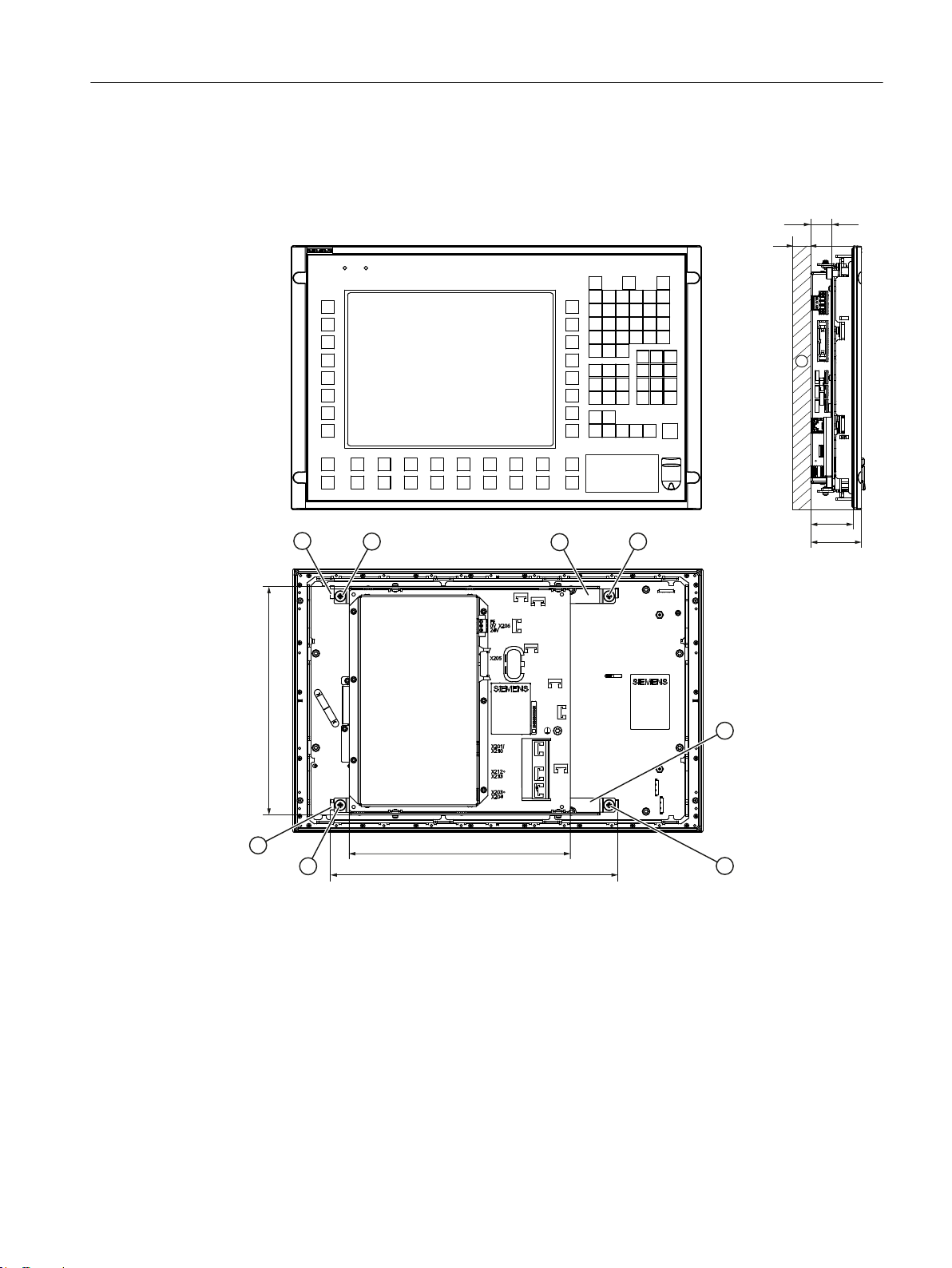
1. Screw the mounting bracket ③ onto the TCU.
2. Use the two hinge catches ① to suspend the TCU mounting bracket unit (like a PCU) in
the operator panel front.
TCU 30.3
20 Manual, 09/2017, A5E40874197
Mounting
3.2 Mounting the TCU on the operator panel front with mounting bracket
3. Insert cables K1, K2 and K3 (only for OP 019).
4. Close the cabled TCU mounting bracket unit and attach it using the four knurled screws
②.
① 2 x hinge catches
② 4 x knurled screws for attaching the mounting brackets to the operator panel front
③ 2 x mounting brackets
④ 10 mm clearance
Figure 3-1 Mounted TCU (example with OP 012) in front, side and rear view
TCU 30.3
Manual, 09/2017, A5E40874197 21

Mounting
3.2 Mounting the TCU on the operator panel front with mounting bracket
NOTICE
Impermissible mounting positions can cause malfunctions
Observe the permissible mounting position: Deviating by up to 5º from the vertical.
Only the shown mounting position is permitted.
TCU 30.3
22 Manual, 09/2017, A5E40874197
7&8
236
Mounting
3.3 Mounting the TCU on the operator panel front without mounting bracket
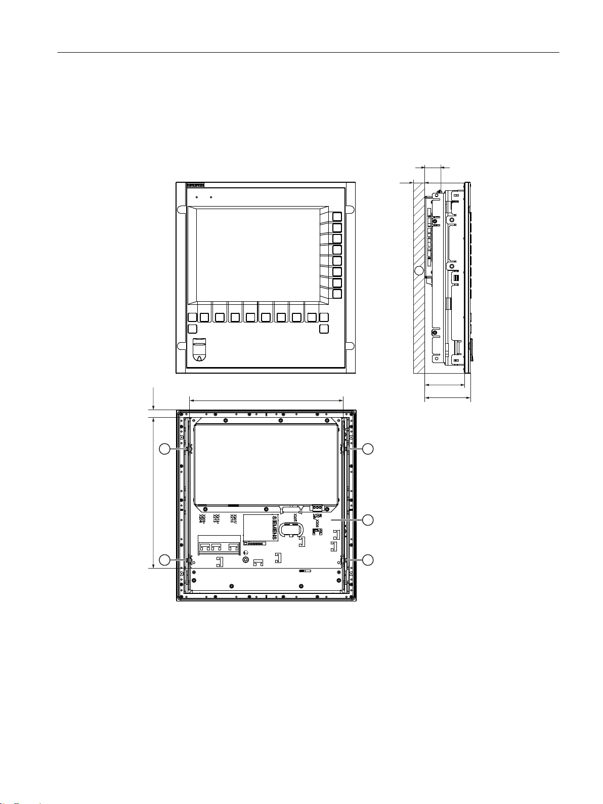
3.3 Mounting the TCU on the operator panel front without mounting
bracket
The OP 010S operator panel front and the TCU can be screwed together without any additional
mounting brackets.
① 4 x M3 screws to fasten the TCU support plate to the OP 010S
② TCU support plate
③ 10 mm clearance
Figure 3-2 Mounted TCU with OP 010S, front, side and rear view
TCU 30.3
Manual, 09/2017, A5E40874197 23

Mounting
3.3 Mounting the TCU on the operator panel front without mounting bracket
NOTICE
Impermissible mounting positions can cause malfunctions
Observe the permissible mounting position: Deviating by up to 5º from the vertical.
TCU 30.3
24 Manual, 09/2017, A5E40874197
Connection
4.1 Pin assignment of the interfaces
The pins of the component interfaces are assigned as specified in the tables below. Any
deviations are indicated at the relevant point.
Signal type
I Input
O Output
B Bidirectional (inputs/outputs)
V Power supply
- Ground (reference potential) or N.C. (not connected)
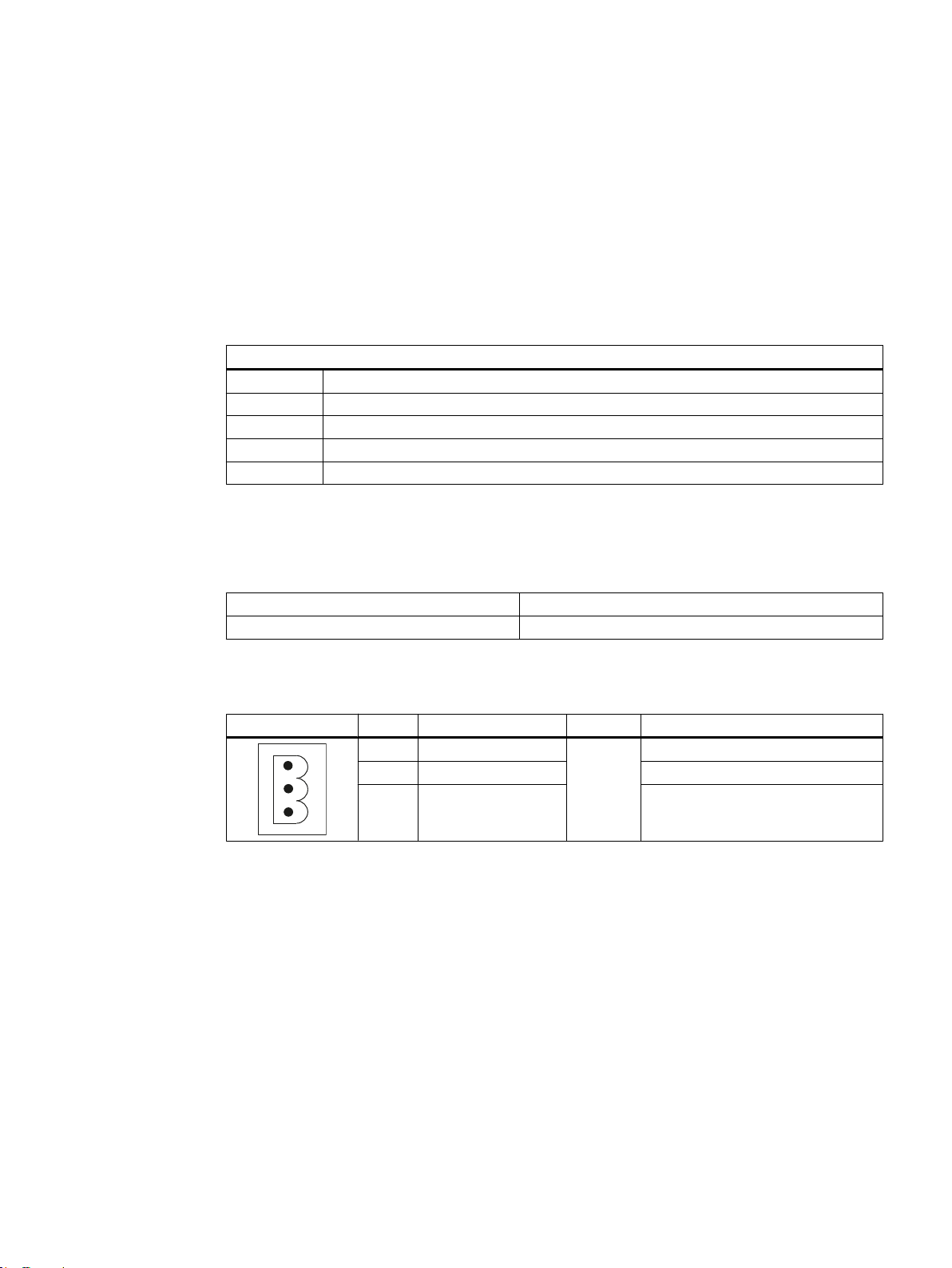
4.1.1 Power supply
Connector type: Terminal block, 3-pin contact strip, screw type
Max. cable length: 10 m
4
Table 4-1 Assignment of the power supply interface
Pin Name Type Meaning
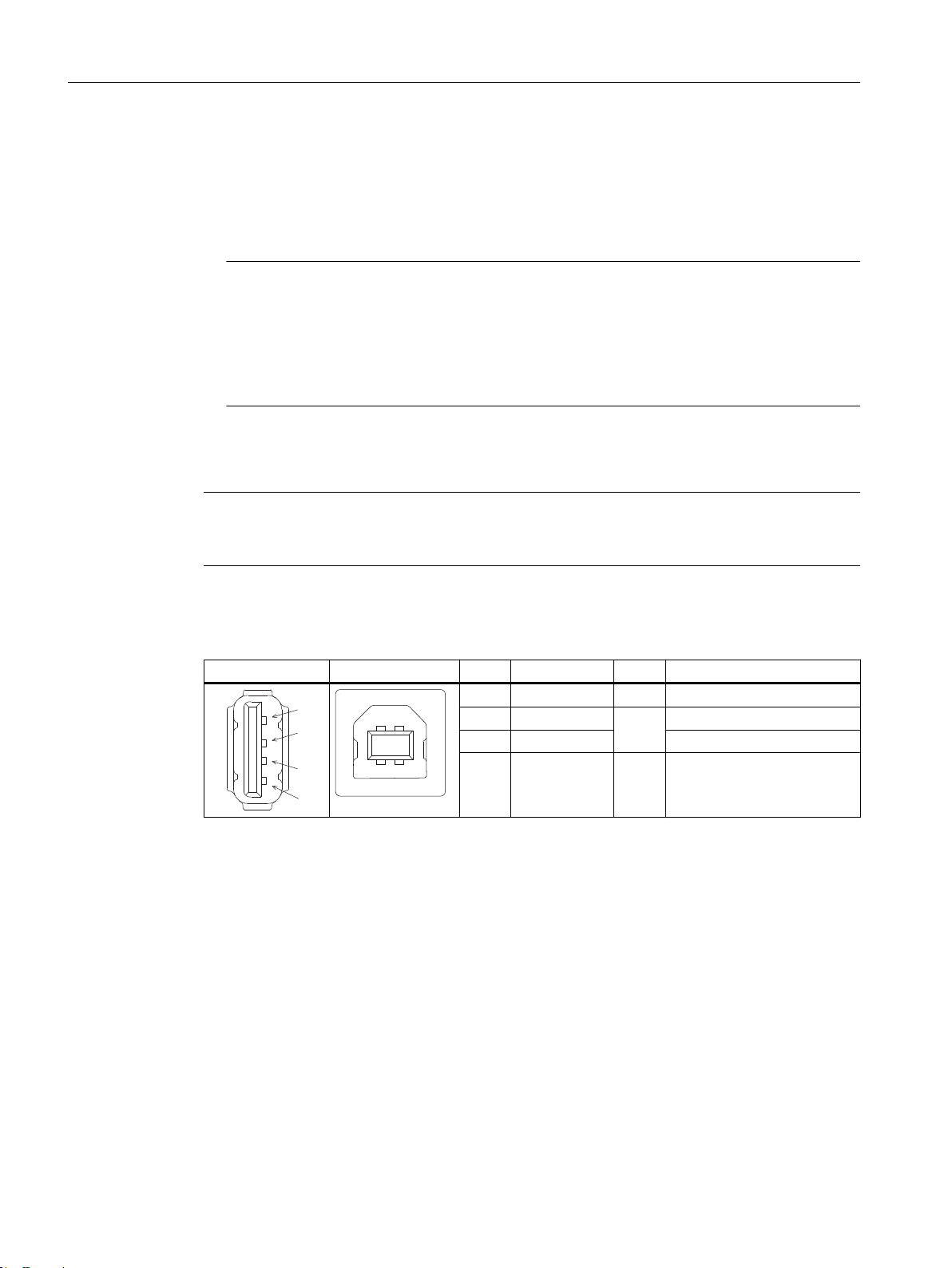
4.1.2 USB interfaces
The USB interfaces are implemented as sockets and comply with the generally valid standard.
The version information (1.1, 2.0 etc.), the maximum velocity (low speed, full speed, etc.) and
the socket type (A or B) are documented in the individual sections for the associated devices.
1 P24 (+)
2 M24 (-) 0 V
3 Functional earth Connection for grounding the hous‐
V/V/-
24 VDC potential (20.4 to 28.8 VDC)
ing
TCU 30.3
Manual, 09/2017, A5E40874197 25
Connection
4.1 Pin assignment of the interfaces
In principle, USB interfaces have the following characteristics:
● Integrated power supply up to 500 mA for each socket.
● Maximum cable length 3 m (Length including the supply cable to the hub and the connected
terminal device; only 1 hub is permitted. It should be noted that some keyboards already
have a hub.)
Note
Cables that are too long can result in malfunctions or faults on the screen
Observe the following restrictions for the USB front interface for connecting operator panels
to the keyboard, mouse or USB FlashDrive:
● Maximum cable length: 1.8 m
● Extension cables are not permissible
● Hot-plugging-capable devices are connected during operation and are identified
automatically.
Note
Correct identification is only guaranteed for USB I/Os that comply to 100% with the USB
specification.
Table 4-2 Assignment of the USB interface
Type A socket Type B socket Pin Name Type Remark
1 P5V_fused V + 5 V (fused)
2 Data3 Data+ Data +
4 GND V Ground (reference potential)
Data -
B
USB sticks
If you want to connect a USB stick to the USB interface, preferably use the tested SIMATIC
USB stick 16 GB for this purpose (Article No.: 6ES7648-0DC60-0AA0). Alternatively, you can
use a USB stick with any memory size. It must, however, meet the following minimum
requirements:
● File system: FAT16 or FAT32
● Partitioning: only in PC partition format (MBR)
USB sticks that deviate from these requirements have not been tested and may not be
recognized by the NCU.
26 Manual, 09/2017, A5E40874197
TCU 30.3
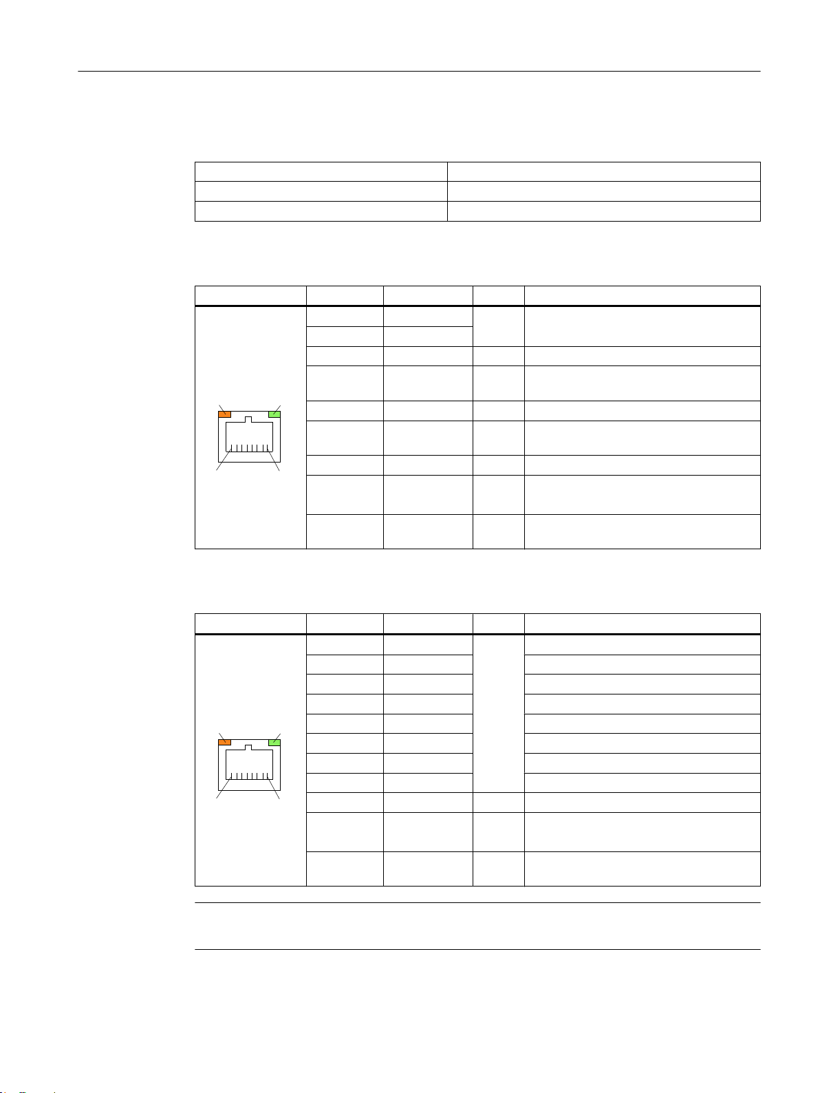
4.1.3 Ethernet RJ45 interface
/('/('
/('/('
Connector type: Standard RJ45 socket
Max. data transmission rate: 10/100/1000 Mbit/s
Max. cable length: 100 m
Table 4-3 Assignment of the Ethernet RJ45 interface 10/100 Mbit/s
Connector Pin Name Type Remark
4/5 GND - (terminated internally with 75 Ω; not re‐
7/8 GND - (terminated internally with 75 Ω; not re‐
Shield - - On connector housing
4.1 Pin assignment of the interfaces
1 TxD+
2 TxD3 RxD+ I Receive data
6 RD- I Receive data
- Green LED
(right)
- Orange LED
(left)
O Transmit data
quired for data transmission)
quired for data transmission)
- Illuminated: 10 or 100 Mbit/s
Off: No or faulty connection
- Illuminated: Data exchange
Off: No data exchange
Connection
Table 4-4 Assignment of the Ethernet RJ45 interface 1000 Mbit/s
Connector Pin Name Type Remark
1 DA+ B Bidirectional pair A+
2 DA- Bidirectional pair A3 DB+ Bidirectional pair B+
4 DC+ Bidirectional pair C+
5 DC- Bidirectional pair C6 DB- Bidirectional pair B7 DD+ Bidirectional pair D+
8 DD- Bidirectional pair D-
Shield - - On connector housing
- Green LED
(right)
- Orange LED
(left)
- Illuminated orange: 1000 Mbit/s
Off: No or faulty connection
- Illuminated: Data exchange
Off: No data exchange
Note
Connection only on LAN, not on telecommunication networks!
TCU 30.3
Manual, 09/2017, A5E40874197 27
 Loading...