

Page 1
SINUMERIK
SINUMERIK 840D sl / 828D / 808D
SINUMERIK Integrate Access
MyMachine /P2P (PC)
Valid for: AMM Software Version V4.7 SP1
CNC Software Version 4.7 SP4
Preface
1
Operating Manual
Introduction
Safety notes
Description
Connection to the control
Operator control (software)
Reference
Troubleshooting/FAQs
2
3
4
5
6
7
8
11/2016
A5E39356962B AA
Page 2
Legal information
Warning notice system
This manual contains notices you have to observe in order to ensure your personal safety, as well as to prevent
damage to property. The notices referring to your personal safety are highlighted in the manual by a safety alert
symbol, notices referring only to property damage have no safety alert symbol. These notices shown below are
graded according to the degree of danger.
DANGER
indicates that death or severe personal injury will result if proper precautions are not taken.
WARNING
indicates that death or severe personal injury may result if proper precautions are not taken.
CAUTION
indicates that minor personal injury can result if proper precautions are not taken.
NOTICE
indicates that property damage can result if proper precautions are not taken.
If more than one degree of danger is present, the warning notice representing the highest degree of danger will be
used. A notice warning of injury to persons with a safety alert symbol may also include a warning relating to property
damage.
Qualified Personnel
The product/system described in this documentation may be operated only by personnel qualified for the specific
task in accordance with the relevant documentation, in particular its warning notices and safety instructions. Qualified
personnel are those who, based on their training and experience, are capable of identifying risks and avoiding
potential hazards when working with these products/systems.
Proper use of Siemens products
Note the following:
WARNING
Siemens products may only be used for the applications described in the catalog and in the relevant technical
documentation. If products and components from other manufacturers are used, these must be recommended or
approved by Siemens. Proper transport, storage, installation, assembly, commissioning, operation and
maintenance are required to ensure that the products operate safely and without any problems. The permissible
ambient conditions must be complied with. The information in the relevant documentation must be observed.
Trademarks
All names identified by ® are registered trademarks of Siemens AG. The remaining trademarks in this publication
may be trademarks whose use by third parties for their own purposes could violate the rights of the owner.
Disclaimer of Liability
We have reviewed the contents of this publication to ensure consistency with the hardware and software described.
Since variance cannot be precluded entirely, we cannot guarantee full consistency. However, the information in
this publication is reviewed regularly and any necessary corrections are included in subsequent editions.
Siemens AG
Division Digital Factory
Postfach 48 48
90026 NÜRNBERG
GERMANY
A5E39356962B AA
Ⓟ 11/2016 Subject to change
Copyright © Siemens AG 2016.
All rights reserved
Page 3

Table of contents
1 Preface.........................................................................................................................................................7
1.1 SINUMERIK documentation.....................................................................................................7
1.2 Target group.............................................................................................................................9
1.3 Hotline and Internet address..................................................................................................10
2 Introduction.................................................................................................................................................11
2.1 Scope of functions and supported SINUMERIK control systems...........................................11
3 Safety notes................................................................................................................................................15
3.1 Fundamental safety instructions for the software documentation (for all product families)......15
3.1.1 Fundamental safety instructions............................................................................................15
3.1.1.1 General safety instructions.....................................................................................................15
3.1.1.2 Industrial security...................................................................................................................16
3.2 Security information on the product.......................................................................................17
4 Description..................................................................................................................................................19
4.1 Structure of the user interface................................................................................................19
4.2 First start................................................................................................................................20
5 Connection to the control............................................................................................................................21
5.1 Establishing a connection to the control system: An overview...............................................21
5.2 Assigning the connection parameters ...................................................................................22
5.2.1 Enable control ports...............................................................................................................22
5.2.1.1 Overview................................................................................................................................22
5.2.1.2 Enabling ports from the HMI..................................................................................................22
5.2.1.3 Otherwise: Enable ports via basesys.ini................................................................................24
5.2.1.4 Otherwise: Enabling ports via the service shell......................................................................25
5.2.2 Assigning parameters for direct connection (peer-to-peer Ethernet).....................................25
5.2.3 Assigning parameters for network connection.......................................................................27
5.2.4 Converting an SSH key file....................................................................................................29
5.3 Establishing the connection...................................................................................................31
5.3.1 Establishing a direct connection (peer-to-peer Ethernet).......................................................31
5.3.2 Establishing a network connection.........................................................................................32
5.4 Disconnect connection ..........................................................................................................35
5.5 Establishing a modem connection.........................................................................................36
5.5.1 General information................................................................................................................36
5.5.2 Setting up the PG/PC interface..............................................................................................37
5.5.3 Parameterize the TeleService adapter IE with the "TeleService" software............................38
5.5.3.1 Overview of TeleService Adapter parameter assignment......................................................38
5.5.3.2 Inserting the system...............................................................................................................39
5.5.3.3 Assigning parameters for the TS Adapter..............................................................................43
5.5.3.4 Administrating the TS Adapter...............................................................................................45
SINUMERIK Integrate Access MyMachine /P2P (PC)
Operating Manual, 11/2016, A5E39356962B AA 3
Page 4

Table of contents
5.5.3.5 Assigning parameters for the internal modem.......................................................................52
5.5.3.6 Testing the connection...........................................................................................................54
5.5.4 Parameterize the TeleService adapter IE without the "TeleService" software.......................59
5.5.5 Establishing a connection/Cabling.........................................................................................60
5.5.6 Create modem connection under Windows 7........................................................................62
5.5.7 Establish modem connection under Windows 7....................................................................67
5.5.8 Create a modem connection under Windows 10...................................................................69
5.5.9 Establish a modem connection under Windows 10...............................................................74
5.5.10 Connecting AMM to the control system via the modem connection......................................75
5.5.11 Further information.................................................................................................................76
6 Operator control (software).........................................................................................................................77
6.1 Remote control of the control system.....................................................................................77
6.1.1 Overview of remote control....................................................................................................77
6.1.2 Approving remote control of the control system on the HMI..................................................78
6.1.2.1 Approving remote control on the HMI....................................................................................78
6.1.2.2 Approving remote control via the control system...................................................................81
6.1.2.3 Further documentation...........................................................................................................82
6.1.3 Functional scope of the remote control..................................................................................82
6.1.3.1 Starting/ending remote control...............................................................................................82
6.1.3.2 Operation...............................................................................................................................85
6.1.3.3 Using remote control to generate the screen of the control system's HMI user interface......87
6.2 Project....................................................................................................................................89
6.2.1 Project overview.....................................................................................................................89
6.2.2 Creating a project (OFFLINE)................................................................................................91
6.2.3 Create a project and read the files from the control system (ONLINE)..................................92
6.2.4 Opening an existing project....................................................................................................95
6.2.5 Closing the project.................................................................................................................99
6.2.6 Deleting a project.................................................................................................................100
6.2.7 Creating a new language.....................................................................................................101
6.2.8 Adding a file.........................................................................................................................103
6.2.9 Deleting a file.......................................................................................................................105
6.2.10 Exporting a file.....................................................................................................................106
6.2.11 Import file.............................................................................................................................109
6.2.12 Edit file.................................................................................................................................111
6.2.13 Compare archives................................................................................................................113
6.2.14 Transferring individual files from the project to the control system......................................115
6.2.15 Transferring individual files from the control to the project...................................................119
6.2.16 Deleting files on the control using the project dialog............................................................121
6.2.17 Recommended procedure when translating files.................................................................124
6.2.18 Activating the alarm text files on the control using an HMI restart.......................................126
6.3 Access to NC file system.....................................................................................................130
6.3.1 NC file system of the 840D sl and 828D controls.................................................................130
6.3.2 NC file system of the 808D control.......................................................................................131
6.4 Backing up/restoring a CompactFlash Card........................................................................133
6.4.1 Overview of backing up/restoring a CompactFlash Card.....................................................133
6.4.2 Generating an image from the CompactFlash Card/USB-FlashDrive..................................133
6.4.3 Writing an image to the CompactFlash Card/USB-FlashDrive............................................135
6.4.4 Writing a SINUMERIK 828D boot system............................................................................136
6.5 CNC Lock function...............................................................................................................139
SINUMERIK Integrate Access MyMachine /P2P (PC)
4 Operating Manual, 11/2016, A5E39356962B AA
Page 5

Table of contents
6.5.1 CNC lock function overview.................................................................................................139
6.5.2 Activating the CNC lock function..........................................................................................139
6.5.3 Extending the CNC lock function.........................................................................................141
6.5.4 Deactivating the CNC lock function......................................................................................144
6.5.5 Reading in Lockset file.........................................................................................................146
6.5.6 Further information...............................................................................................................147
7 Reference.................................................................................................................................................149
7.1 Supported files.....................................................................................................................149
7.2 Languages supported by SINUMERIK Operate...................................................................151
7.3 Toolbar.................................................................................................................................152
7.4 View overview......................................................................................................................153
7.5 Data structure on the CompactFlash Card system..............................................................155
7.5.1 Data structure on the CompactFlash card (SINUMERIK 840D sl / 828D)...........................155
7.5.2 Data structure on the system CompactFlash card (SINUMERIK 808D)..............................158
7.5.3 Editing a file externally.........................................................................................................159
7.6 Open source software / licenses..........................................................................................161
8 Troubleshooting/FAQs..............................................................................................................................163
8.1 Password forgotten..............................................................................................................163
8.2 Trace files for error correction..............................................................................................164
8.3 Problems connecting to the control......................................................................................165
8.4 Setting up series machines..................................................................................................166
8.5 840D sl: Activate remote control for the VNC Viewer. ........................................................167
8.6 CNC Lock function...............................................................................................................170
8.7 Activating the alarm text files on the control using an HMI restart.......................................171
8.8 Recommended procedure when translating files.................................................................174
8.9 Backing up commissioning data on the control....................................................................177
Index.........................................................................................................................................................179
SINUMERIK Integrate Access MyMachine /P2P (PC)
Operating Manual, 11/2016, A5E39356962B AA 5
Page 6

Table of contents
SINUMERIK Integrate Access MyMachine /P2P (PC)
6 Operating Manual, 11/2016, A5E39356962B AA
Page 7

Preface
1.1 SINUMERIK documentation
SINUMERIK documentation
The SINUMERIK documentation is organized in the following categories:
● General documentation
● User documentation
● Manufacturer/service documentation
Additional information
1
You can find information on the following topics at the link (
motioncontrol/docu):
● Ordering documentation / overview of documentation
● Additional links to download documents
● Using documentation online (find and search in manuals/information)
Please send an e-mail (mailto:docu.motioncontrol@siemens.com) if you have any questions
about the technical documentation (e.g. suggestions for improvement, corrections) to:
My Documentation Manager (MDM)
Under the following link (http://www.siemens.com/mdm) you will find information to individually
compile OEM-specific machine documentation based on the Siemens content:
Training
For information about the range of training courses, refer to:
● SITRAIN (www.siemens.com/sitrain) - training courses from Siemens for automation
products, systems and solutions
● SinuTrain (www.siemens.com/sinutrain) - training software for SINUMERIK
http://www.siemens.com/
FAQs
You can find Frequently Asked Questions in the Service & Support pages (www.siemens.com/
automation/service&support) at Product Support.
SINUMERIK Integrate Access MyMachine /P2P (PC)
Operating Manual, 11/2016, A5E39356962B AA 7
Page 8

Preface
1.1 SINUMERIK documentation
SINUMERIK
You can find information on SINUMERIK at the following link. (
sinumerik)
http://www.siemens.com/
SINUMERIK Integrate Access MyMachine /P2P (PC)
8 Operating Manual, 11/2016, A5E39356962B AA
Page 9

1.2 Target group
Target group
This documentation is intended for operators of the "SINUMERIK Integrate Access
MyMachine /P2P (PC)" software and teaches them how to utilize all the software functions
correctly and completely.
Benefits
The operating manual familiarizes the target group with the control elements and commands.
Based on the manual, the target group is capable of responding to problems and to take
corrective action.
Standard scope
This documentation only describes the functionality of the standard scope. Additions or
revisions made by the machine manufacturer are documented by the machine manufacturer.
Preface
1.2 Target group
Other functions not described in this documentation might be executable in the control. This
does not, however, represent an obligation to supply such functions with a new control or when
servicing.
For the sake of simplicity, this documentation does not contain all detailed information about
all types of the product and cannot cover every conceivable case of installation, operation, or
maintenance.
SINUMERIK Integrate Access MyMachine /P2P (PC)
Operating Manual, 11/2016, A5E39356962B AA 9
Page 10

Preface
1.3 Hotline and Internet address
1.3 Hotline and Internet address
Technical Support
You can find country-specific telephone numbers for technical support on the Internet at the
following address: Product support (
www.siemens.com/automation/service&support).
SINUMERIK Integrate Access MyMachine /P2P (PC)
10 Operating Manual, 11/2016, A5E39356962B AA
Page 11

Introduction
2.1 Scope of functions and supported SINUMERIK control systems
The "SINUMERIK Integrate Access MyMachine /P2P (PC)" tool (previously "RCS
Commander") supports the commissioning and maintenance of machines with SINUMERIK
Operate as of software version 2.6 using a standard Windows PC.
From here on, the following terms/abbreviations are used synonymously in this document:
"Access MyMachine" and "AMM".
Functionality
AMM allows simple file management on your PC and on the SINUMERIK controls.
AMM provides the following functions:
● Exchanging data between the SINUMERIK control and your PC.
● Generating and restoring an image from the CompactFlash card of your control to backup
data.
● Writing images to a CompactFlash card.
● Loading of all files relevant for the commissioning directly to the CompactFlash card of your
SINUMERIK control, and loading these files from the control to your PC.
2
● Managing the NC data of the SINUMERIK control (part programs: *.mpf, *.spf).
You can copy files directly from the PC to the NC and from the NC to the PC.
● Process monitoring and remote control of the SINUMERIK via a remote control function
using VNC.
● Saving the screenshot of the HMI on the PC.
This function is used to represent your control and improves support in the event of an error.
● User-friendly editing of the following OEM files on the PC (Page 149):
– PLC alarm texts
– Color attribute files
– Configuration files
– Cycle alarm texts
– Part program messages
– EasyScreen files
– Tool management texts
– EasyExtend files
– Maintenance scheduler files
– Archives
● Creating and loading an archive from the control.
SINUMERIK Integrate Access MyMachine /P2P (PC)
Operating Manual, 11/2016, A5E39356962B AA 11
Page 12

Introduction
2.1 Scope of functions and supported SINUMERIK control systems
● Comparing and loading archives with the aid of the SINUMERIK Integrate "Create MyConfig
- Diff" software.
● Managing the OEM files mentioned above with the following options (Page 89):
– Creating a project OFFLINE.
– Creating a project for which the OEM files mentioned above are automatically copied
from the control.
– Copying individual files using the project dialog to the control or copying from the control
to the project.
– Deleting the OEM files using the project dialog on the control.
● Converting alarm texts from powerline format to solution line format.
● CNC lock function
Using the CNC lock function, you can activate, extend or deactivate a date in the control
as of which the NC Start is locked.
Supported SINUMERIK controls
The following SINUMERIK controls are supported:
Foreign languages
● SINUMERIK 840D sl (NCUs)
● SINUMERIK 828D (PPUs)
● SINUMERIK 808D (as of AMM version 4.6, PPU141.2 and PPU161.2)
● The AMM itself can be switched into various interface languages. The following languages
are available:
– German
– English
– Chinese (Simpl.)
– Chinese (Trad.)
– Spanish
– Italian
– French
– Portuguese (Braz.)
– Japanese
– Korean
– Russian
● The HMI of the control can also handle several language packages and the associated
language selection. The creation and installation of such language packages and/or
individual language files is supported by the AMM in the project.
SINUMERIK Integrate Access MyMachine /P2P (PC)
12 Operating Manual, 11/2016, A5E39356962B AA
Page 13

Connections
Introduction
2.1 Scope of functions and supported SINUMERIK control systems
In Windows, activate the support for Asian languages at "Region and Language" so that Asian
characters are displayed correctly.
The following connections to a SINUMERIK solution line control are available:
● Modem (56k)
via TeleService Adapter IE on X127
● Peer-to-peer Ethernet
● Ethernet network
SINUMERIK Integrate Access MyMachine /P2P (PC)
Operating Manual, 11/2016, A5E39356962B AA 13
Page 14

Introduction
2.1 Scope of functions and supported SINUMERIK control systems
SINUMERIK Integrate Access MyMachine /P2P (PC)
14 Operating Manual, 11/2016, A5E39356962B AA
Page 15
Safety notes
3
3.1 Fundamental safety instructions for the software documentation (for all product families)
3.1.1 Fundamental safety instructions
3.1.1.1 General safety instructions
WARNING
Danger to life if the safety instructions and residual risks are not observed
If the safety instructions and residual risks in the associated hardware documentation are not
observed, accidents involving severe injuries or death can occur.
● Observe the safety instructions given in the hardware documentation.
● Consider the residual risks for the risk evaluation.
WARNING
Danger to life or malfunctions of the machine as a result of incorrect or changed
parameterization
As a result of incorrect or changed parameterization, machines can malfunction, which in turn
can lead to injuries or death.
● Protect the parameterization (parameter assignments) against unauthorized access.
● Respond to possible malfunctions by applying suitable measures (e.g. EMERGENCY
STOP or EMERGENCY OFF).
SINUMERIK Integrate Access MyMachine /P2P (PC)
Operating Manual, 11/2016, A5E39356962B AA 15
Page 16
Safety notes
3.1 Fundamental safety instructions for the software documentation (for all product families)
3.1.1.2 Industrial security
Note
Industrial security
Siemens provides products and solutions with industrial security functions that support the
secure operation of plants, systems, machines and networks.
In order to protect plants, systems, machines and networks against cyber threats, it is
necessary to implement – and continuously maintain – a holistic, state-of-the-art industrial
security concept. Siemens products and solutions only represent one component of such a
concept.
The customer is responsible for preventing unauthorized access to its plants, systems,
machines and networks. Systems, machines and components should only be connected to
the enterprise network or the internet if and to the extent necessary and with appropriate
security measures (e.g. use of firewalls and network segmentation) in place.
Additionally, Siemens’ guidance on appropriate security measures should be taken into
account. For more information about industrial security, please visit:
Industrial security (http://www.siemens.com/industrialsecurity).
Siemens’ products and solutions undergo continuous development to make them more secure.
Siemens strongly recommends to apply product updates as soon as available and to always
use the latest product versions. Use of product versions that are no longer supported, and
failure to apply latest updates may increase customer’s exposure to cyber threats.
To stay informed about product updates, subscribe to the Siemens Industrial Security RSS
Feed at:
Industrial security (http://www.siemens.com/industrialsecurity).
WARNING
Danger to life as a result of unsafe operating states resulting from software manipulation
Software manipulations (e.g. viruses, trojans, malware or worms) can cause unsafe operating
states in your system that may lead to death, serious injury, and property damage.
● Keep the software up to date.
● Incorporate the automation and drive components into a holistic, state-of-the-art industrial
security concept for the installation or machine.
● Make sure that you include all installed products into the holistic industrial security concept.
● Protect files stored on exchangeable storage media from malicious software by with
suitable protection measures, e.g. virus scanners.
SINUMERIK Integrate Access MyMachine /P2P (PC)
16 Operating Manual, 11/2016, A5E39356962B AA
Page 17

3.2 Security information on the product
NOTICE
No confidential data on the control and in the AMM project
Confidential data must not be loaded to the control and not downloaded to the AMM project
from there. The data is not adequately protected there.
This applies particularly to confidential data that is not part of SINUMERIK.
NOTICE
Misuse of data
Note that it is essential to use secure data storage when saving your AMM-relevant data particularly your confidential data. It is best to store this data encrypted locally or encrypted
on the network. Make sure that this data cannot be accessed by unauthorized personnel.
This applies to the following data:
● SSH key files
● Archive files
● Image files
● Project files
● Trace files
● Safety-relevant files
Safety notes
3.2 Security information on the product
Further information on secure data storage can be found in the Auto-Hotspot.
NOTICE
Danger due to insecure Internet connection
Make sure that before establishing a network connection, your PC is connected to the Internet
via a secure connection (VPN connection). This also applies to connections via VNC Viewer.
This VPN connection can be made, for example, with a SCALANCE S Security Module. Note
the security-relevant information when using the SCALANCE S Module. Further information
on the use of SCALANCE S can be found in the Auto-Hotspot.
NOTICE
Security risk through administrator rights
If you operate AMM on a PC with permanent administrator rights, there is an increased
security risk. Therefore, ensure that there is a secure operating environment for AMM, and
only assign administrator rights temporarily and selectively.
Further information on the secure administration of user accounts and the assignment of
rights can be found in the Auto-Hotspot.
SINUMERIK Integrate Access MyMachine /P2P (PC)
Operating Manual, 11/2016, A5E39356962B AA 17
Page 18

Safety notes
3.2 Security information on the product
See also
Industrial Security Configuration Manual (
108862708)
https://support.industry.siemens.com/cs/us/en/view/
SINUMERIK Integrate Access MyMachine /P2P (PC)
18 Operating Manual, 11/2016, A5E39356962B AA
Page 19
Description
4.1 Structure of the user interface
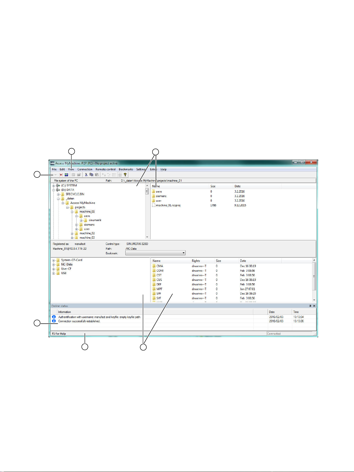
AMM user interface
The following shows an overview of the AMM user interface with the most important windows,
status indicators and operator controls.
4
① Main menu
② View of the computer file system (local file system)
③ View of the file system of the connected control (remote file system)
④ Status bar
⑤ Status window for messages concerning the connection and actions in the control.
⑥ Toolbar
Figure 4-1 User interface
SINUMERIK Integrate Access MyMachine /P2P (PC)
Operating Manual, 11/2016, A5E39356962B AA 19
Page 20
Description
4.2 First start
4.2 First start
Operating sequence
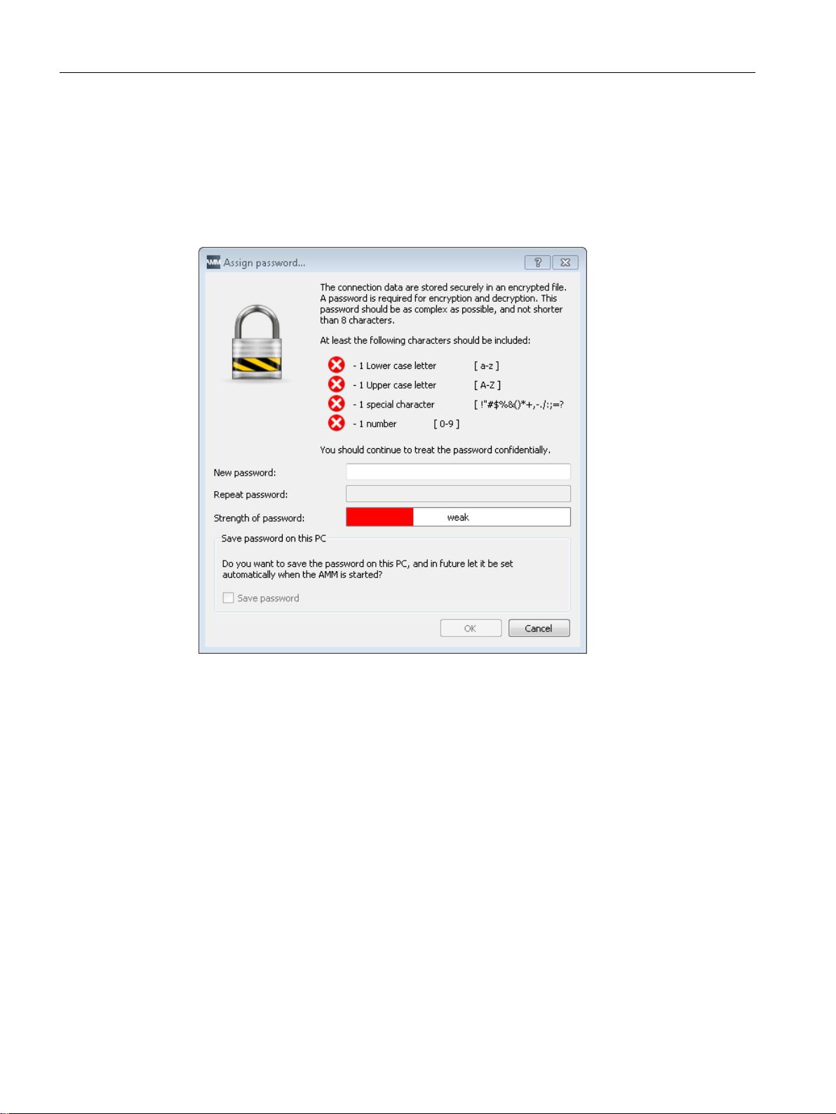
The following prompts appear when AMM is started for the first time:
1. Enter a password. AMM always requires a password when started for the first time.
Figure 4-2 Enter password
– With the password, the file with the connection data of AMM is encrypted.
– The password can be subsequently changed at any time.
– In order to change the password, the previously entered password must be entered to
ensure that only authorized users change the password.
2. Press "OK".
AMM starts up with the language set in Windows.
If the relevant language is not available in AMM, English is automatically set.
The set language can be changed at any time via AMM.
3. If earlier versions of AMM are installed on your PG/PC, you are given the option of accepting
the connection data of the earlier versions. Confirm the acceptance of the data with "Yes"
or reject with "No".
You have successfully completed the first start of AMM. You can now use all the functions of
AMM.
SINUMERIK Integrate Access MyMachine /P2P (PC)
20 Operating Manual, 11/2016, A5E39356962B AA
Page 21

Connection to the control
5.1 Establishing a connection to the control system: An overview
AMM offers two options for establishing a connection to a control system:
1. Direct connection (peer-to-peer Ethernet)
Direct connection involves connecting the PG/PC to the control system's X127 interface
directly.
You can establish this type of connection if you are where the control system is located.
Note
The SINUMERIK 808 control uses the X130 interface instead of the X127 interface for a
direct connection. Follow the corresponding control manuals when assigning parameters.
2. Network connection
A network connection is a connection between the PG/PC and the control system via a
local area network (LAN).
This type of connection is also possible if the control system is at another location.
Note
Connection via modem is a special feature.
5
See also
You will find a manual explaining how a modem connection is set up (e.g. via TS adapter
IE (analog)) at Establishing a modem connection (Page 36).
Assigning parameters for direct connection (peer-to-peer Ethernet) (Page 25)
Assigning parameters for network connection (Page 27)
Establishing a direct connection (peer-to-peer Ethernet) (Page 31)
Establishing a network connection (Page 32)
Establishing a modem connection (Page 36)
SINUMERIK Integrate Access MyMachine /P2P (PC)
Operating Manual, 11/2016, A5E39356962B AA 21
Page 22

Connection to the control
5.2 Assigning the connection parameters
5.2 Assigning the connection parameters
5.2.1 Enable control ports
5.2.1.1 Overview
You must access port 22 to establish a connection from AMM to the control. You must access
port 5900 to establish a connection from AMM via remote control.
Three ways of enabling a port are described below for each port access required.
● Enabling ports from the HMI (Page 22)
● Otherwise: Enable ports via basesys.ini (Page 24)
● Otherwise: Enabling ports via the service shell (Page 25)
Note
Ports on the SINUMERIK 808D and 828D controls can only be enabled from the user interface.
5.2.1.2 Enabling ports from the HMI
Operating sequence for 840D sl/828D controls
1. Open the "Commissioning > Network" menu on your control.
2. Open extended horizontal softkeys with the right arrow key.
3. Open the "Workplace network" menu on your control.
4. The "Workplace network settings" window opens.
SINUMERIK Integrate Access MyMachine /P2P (PC)
22 Operating Manual, 11/2016, A5E39356962B AA
Page 23
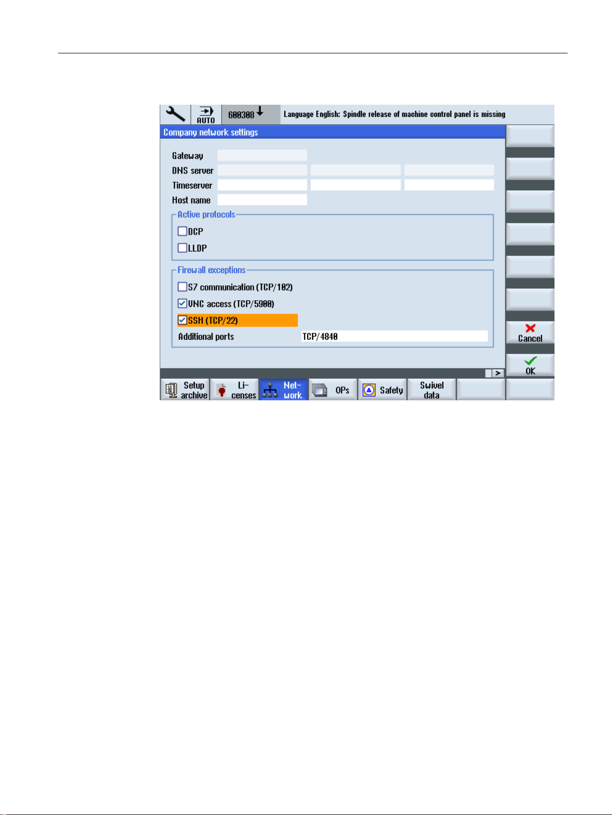
5. Press the "Change" softkey.
Connection to the control
5.2 Assigning the connection parameters
Figure 5-1 Settings of the 840 sl workplace network
6. Set a check mark in the "Firewall exceptions" area for the following options:
– VNC access (TCP/5900)
– SSH (TCP/22)
Use the arrow keys of your control to select the particular port. Use the SELECT button to
enable/disable the particular port.
7. Select "OK" to save the changes.
8. Restart the control to make the changes effective.
Operating sequence for an 808D control
1. Change to the <SYSTEM> operating area with the shortcut <Shift> + <SYSTEM ALARM>.
2. Open extended horizontal softkeys with the right arrow key.
3. Press the "Serv. display" and "Service control" softkeys.
SINUMERIK Integrate Access MyMachine /P2P (PC)
Operating Manual, 11/2016, A5E39356962B AA 23
Page 24
Connection to the control
5.2 Assigning the connection parameters
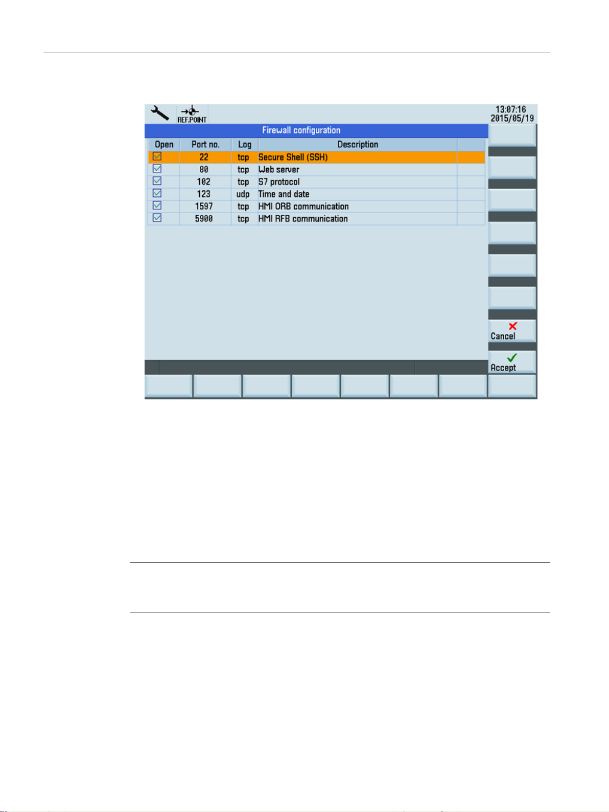
4. Open "Firewall configuration" via "Service network".
Figure 5-2 Firewall settings for the 808D
5. Select the desired port with the cursor.
6. Press the "INPUT" key to disable the selected port.
7. Select the "Accept" softkey to save the changes.
8. Restart the control to make the changes effective.
5.2.1.3 Otherwise: Enable ports via basesys.ini
Note
The port enable procedure applies only to the following SINUMERIK control:
● SINUMERIK 840D sl
Operating sequence
1. Open the "/user/system/etc/basesys.ini" file on your control.
2. Under the variable "FirewallOpenPorts" enter the port "TCP/22" or if needed the port "TCP/
5900".
3. Restart the control to make the changes effective.
SINUMERIK Integrate Access MyMachine /P2P (PC)
24 Operating Manual, 11/2016, A5E39356962B AA
Page 25

5.2.1.4 Otherwise: Enabling ports via the service shell
Note
The port enable procedure applies only to the following SINUMERIK control:
● SINUMERIK 840D sl
Operating sequence
1. Open a service shell on the TCU.
2. Enter the command "sc openport tcp/22 <IP Address>".
3. This command opens port 22 in the firewall on the workplace network (X130) for a default
time of 15 minutes. The default time can be adjusted via the option -MINUTES. The
maximum possible time is 60 minutes.
If necessary you can repeat the command for port 5900.
Connection to the control
5.2 Assigning the connection parameters
5.2.2 Assigning parameters for direct connection (peer-to-peer Ethernet)
Requirement
● You are connected to the X127 interface of the control by an Ethernet cable.
Note
The SINUMERIK 808 control uses the X130 interface instead of the X127 interface for a
direct connection. Follow the corresponding control manuals when assigning parameters.
● The SSH port 22 in the firewall to the company network is enabled (Page 22).
SINUMERIK Integrate Access MyMachine /P2P (PC)
Operating Manual, 11/2016, A5E39356962B AA 25
Page 26
Connection to the control
5.2 Assigning the connection parameters
Operating sequence
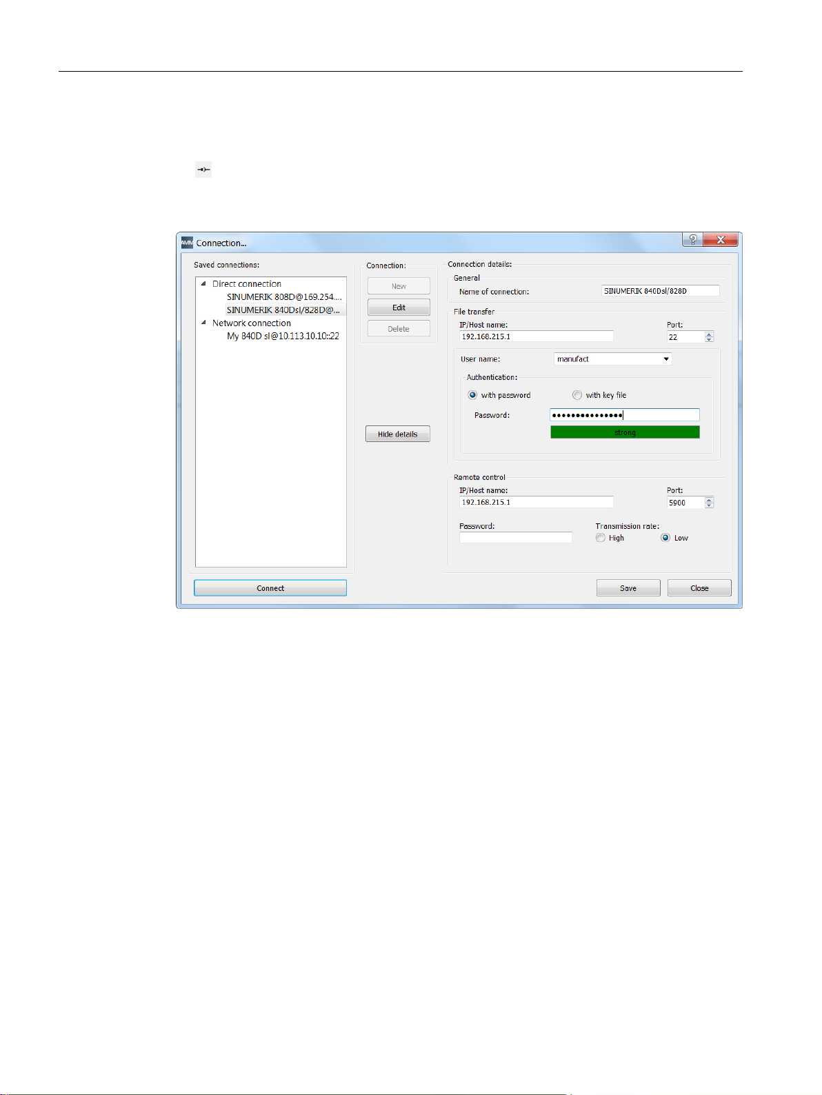
1. Press the "Connection" icon.
- OR Select "Connection" > "Connect..." in the main window menu.
The following dialog appears:
Figure 5-3 Settings for direct connection
2. Select a direct connection, and click the "Edit" button.
SINUMERIK Integrate Access MyMachine /P2P (PC)
26 Operating Manual, 11/2016, A5E39356962B AA
Page 27

Connection to the control
5.2 Assigning the connection parameters
3. A direct connection is always established through the IP address 192.168.215.1 or IP
169.254.11.22 and via port 22.
Enter the following authentication data:
– Select a user name and enter the appropriate password.
OR
– Select a user name and an SSH key file (Page 29).
NOTICE
The SSH key file must be available in OpenSSH format and must also be password
protected.
Note
If the authentication fields are not filled in, the authentication prompt appears on its own
when establishing the connection.
Note
Note that the same access levels should be activated in the HMI and in AMM in order
to avoid error sources.
4. Press "Save".
See also
Establishing a connection to the control system: An overview (Page 21)
5.2.3 Assigning parameters for network connection
Requirement
● You are connected to the X130 interface of the control by an Ethernet cable.
● The ports required in the firewall to the company network are enabled (Page 22).
SINUMERIK Integrate Access MyMachine /P2P (PC)
Operating Manual, 11/2016, A5E39356962B AA 27
Page 28
Connection to the control
5.2 Assigning the connection parameters
Operating sequence
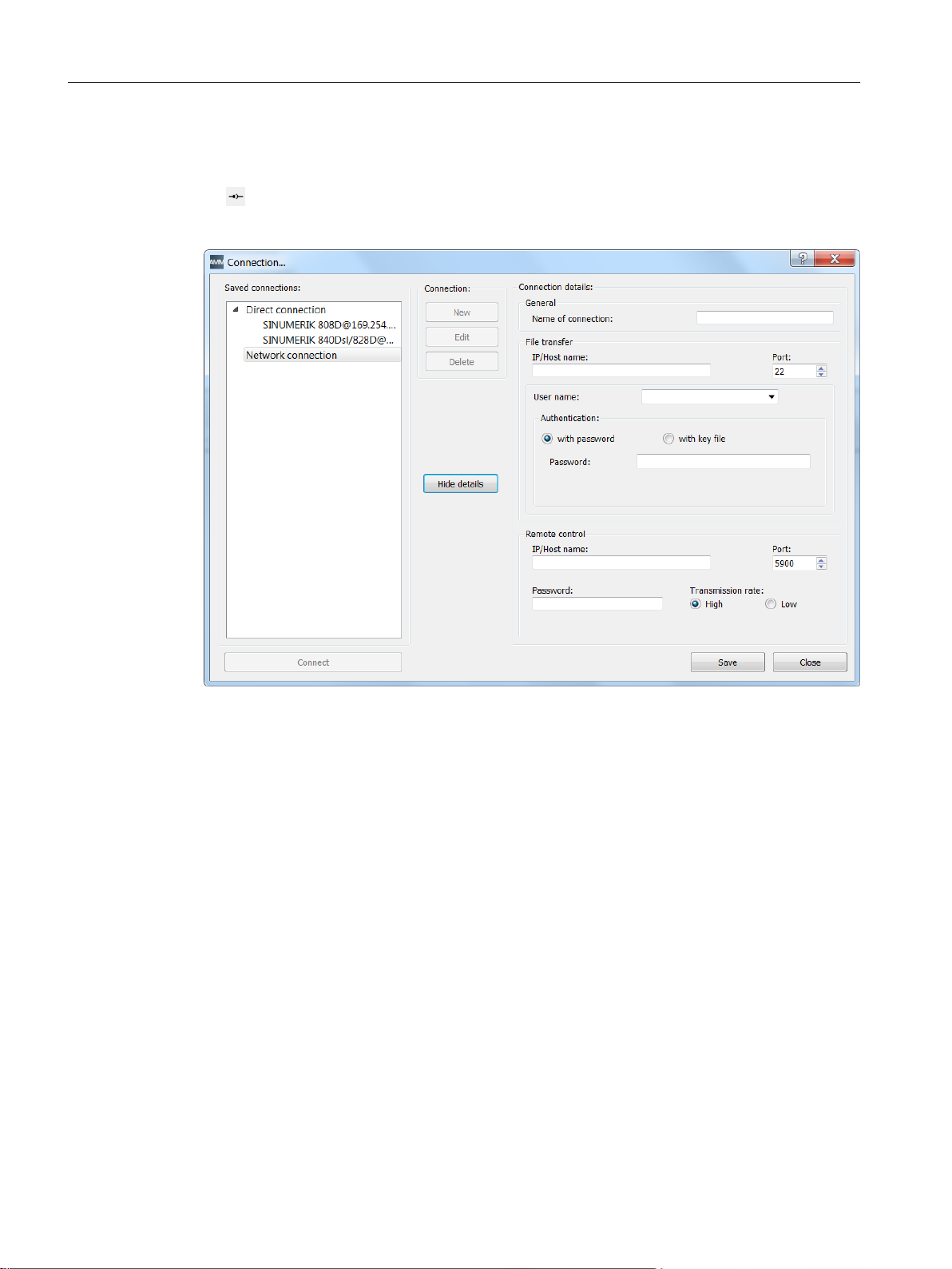
1. Press the "Connection" icon.
- OR Select "Connection > Connect..." in the main window menu. The following dialog appears:
Figure 5-4 Network connection
2. Press "New" to create a new connection.
3. Select a suitable connection name.
4. When establishing a network connection to the control, select the IP address and the port
22 of the control.
SINUMERIK Integrate Access MyMachine /P2P (PC)
28 Operating Manual, 11/2016, A5E39356962B AA
Page 29

Connection to the control
5.2 Assigning the connection parameters
5. Enter the following authentication data:
– Select a user name and enter the appropriate password.
OR
– Select a user name and an SSH key file (Page 29).
NOTICE
The SSH key file must be available in OpenSSH format and must also be password
protected.
Note
If the authentication fields are not filled in, the authentication prompt appears on its own
when establishing the connection.
Note
Note that the same access levels should be activated in the HMI and in AMM in order
to avoid error sources.
6. If the control is remote controlled, enter the IP address of the control and port 5900.
7. Set the desired transmission rate.
Note
The transmission rate "low" should be selected for a connection via a modem.
Also select the transmission rate "low" if the network connection is poor. This will ensure
that you can also operate the control remotely if the network connection is poor.
"High" can be selected if the network connection is good. This setting displays the control's
screen with a higher color resolution.
This setting has no effect on file operations such as "Copy".
8. Press "Save".
The new network connection will be saved and added.
See also
Establishing a connection to the control system: An overview (Page 21)
5.2.4 Converting an SSH key file
As of software version V4.7, the key file must have a specific format for authentication via SSH
on a control. You can convert this format, for example with the aid of PuTTYgen software. The
PuTTYgen program is a freely available open source program for Windows.
SINUMERIK Integrate Access MyMachine /P2P (PC)
Operating Manual, 11/2016, A5E39356962B AA 29
Page 30

Connection to the control
5.2 Assigning the connection parameters
Requirement
This description is applicable to the PuTTYgen version 0.64:
Note
Note the central security information in Section Auto-Hotspot.
Operating sequence
Result
1. Download the PuTTYgen program from the Internet (
~sgtatham/putty/download.html).
2. Start the program.
3. Load the key file via "Load".
Note
If the key file is not shown, change the file extension to "*.*".
4. Select "Conversions > Export OpenSSH key" in the menu.
5. Select a password via the "Key passphrase" input field and confirm the assigned password
in the "Confirm passphrase" input field.
NOTICE
The SSH key file must be password protected.
6. Assign a file name and click "Save".
Note
The file name does not need an extension. The string length is not specifically limited.
http://www.chiark.greenend.org.uk/
You can now use the key file for authentication in AMM.
SINUMERIK Integrate Access MyMachine /P2P (PC)
30 Operating Manual, 11/2016, A5E39356962B AA
Page 31

5.3 Establishing the connection
5.3 Establishing the connection
5.3.1 Establishing a direct connection (peer-to-peer Ethernet)
Operating sequence
1. There are two ways of establishing a "direct connection":
– Select "Connection" > "Connect..." in the main window menu.
Connection to the control
– Press the "Connect" button
Select the direct connection from a selection dialog.
in the toolbar to set up a connection.
Figure 5-5 Direct connections
2. Press the "Connect" button.
3. If the authentication data for the direct connection has already been saved, a connection
to the control is set up immediately.
If not, a dialog for entering the authentication data opens.
See also
Establishing a connection to the control system: An overview (Page 21)
Industrial Security Configuration Manual (https://support.industry.siemens.com/cs/us/en/view/
108862708)
SINUMERIK Integrate Access MyMachine /P2P (PC)
Operating Manual, 11/2016, A5E39356962B AA 31
Page 32

Connection to the control
5.3 Establishing the connection
5.3.2 Establishing a network connection
Requirement
Note
Note the central security information in Section Auto-Hotspot.
SINUMERIK Integrate Access MyMachine /P2P (PC)
32 Operating Manual, 11/2016, A5E39356962B AA
Page 33
Operating sequence
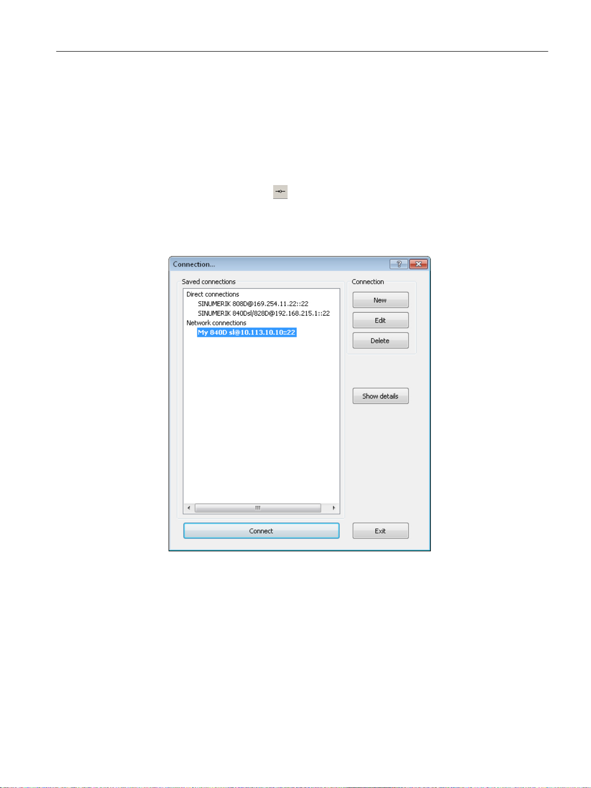
1. The following ways of establishing a "network connection" are available:
Connection to the control
5.3 Establishing the connection
– Select "Connection" in the main window menu.
The last five network connections are offered for selection.
Select one of the menu entries.
The connection to the selected control is established.
- OR -
– Press the "Connection"
button in the toolbar.
- OR -
– Select "Connection" > "Connect..." in the main window menu.
A selection dialog opens, in which you still have to select the corresponding connection.
All the saved connections are available for selection here.
Figure 5-6 Select connection...
2. Press the "Connect" button in the selection dialog.
3. If a selection dialog containing only the direct connection opens when you press the
"Connect" button in the toolbar, this means you have not yet parameterized any network
connections. Parameters have to be assigned to them in advance. Proceed as described
in Section Assigning parameters for network connection (Page 27).
4. If you have not entered any authentication data, a dialog for entering the authentication
data opens.
SINUMERIK Integrate Access MyMachine /P2P (PC)
Operating Manual, 11/2016, A5E39356962B AA 33
Page 34

Connection to the control
5.3 Establishing the connection
See also
Establishing a connection to the control system: An overview (Page 21)
SINUMERIK Integrate Access MyMachine /P2P (PC)
34 Operating Manual, 11/2016, A5E39356962B AA
Page 35
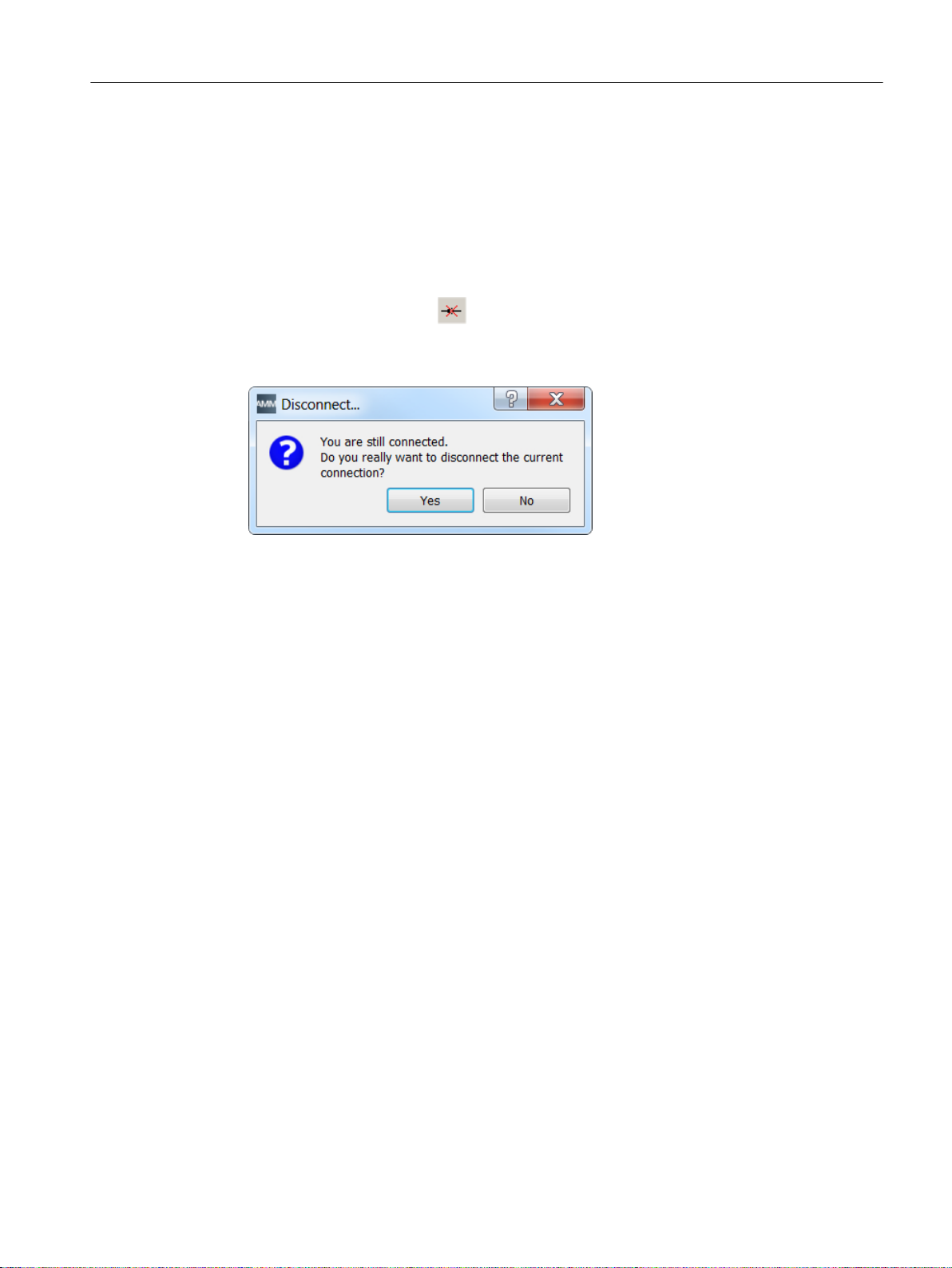
5.4 Disconnect connection
You can disconnect a current connection to the control. Note that disconnecting the connection
to the control also ends the remote control of your control.
Operating sequence
1. There are two ways of disconnecting an active connection:
– Press the "Disconnect" button in the toolbar.
– Select "Connection > Disconnect" in the main window menu.
2. Confirm the prompt dialog with "Yes".
Connection to the control
5.4 Disconnect connection
SINUMERIK Integrate Access MyMachine /P2P (PC)
Operating Manual, 11/2016, A5E39356962B AA 35
Page 36

'VO
7&8
1&8
7HOH6HUYLFH$GDSWHU,(
,QWHUDFWLRQ
(WKHUQHWFRQQHFWLRQ
*HQHUDOWHOHSKRQH
QHWZRUN
;
WHUPLQDO
;
WHUPLQDO
;
WHUPLQDO
/RFDO3&
NPRGHPFRQQHFWLRQ
NPR
GHP
FR
QQHFW
LRQ
Connection to the control
5.5 Establishing a modem connection
5.5 Establishing a modem connection
5.5.1 General information
There are various ways to set up a modem connection from the PC to the control.
This brief guide describes a modem connection to the 840D sl control using the
TeleService Adapter IE (TS Adapter).
This brief guide describes the following two options for the parameterization:
● TeleService Adapter with the "TeleService" software
● TeleService Adapter without the "TeleService" software
The "TeleService" software is included with the TeleService Adapter. More information about
the software can be found in the Help for the TeleService adapter.
Figure 5-7 Modem connection from the PC to the control via the network and the TeleService Adapter IE
Note
You can only establish (Page 60) the connection/cabling as shown in the figure after you have
assigned parameters (Page 38) for the TeleService Adapter IE with the PC.
36 Operating Manual, 11/2016, A5E39356962B AA
SINUMERIK Integrate Access MyMachine /P2P (PC)
Page 37

See also
Setting up the PG/PC interface (Page 37)
Establishing a connection/Cabling (Page 60)
Parameterize the TeleService adapter IE with the "TeleService" software (Page 38)
Parameterize the TeleService adapter IE without the "TeleService" software (Page 59)
5.5.2 Setting up the PG/PC interface
Operating sequence
During the installation of the "TeleService" software you are prompted to set up the PG/PC
interface
.
1. Check the dialog box "Set up PG/PC interface".
Connection to the control
5.5 Establishing a modem connection
– If the "TS Adapter IE" interface is included in the selection list, go to
step 5.
– If the "TS Adapter IE" interface is missing from the list, continue with
step 2.
2. To add or remove interfaces, click
"Select...".
The "Install/Remove Interface" dialog box opens.
3. Select the "TS Adapter IE" module from the selection list and
install the adapter.
4. Click "Close" to close the dialog box.
5. In the "Set up PG/PC interface" dialog box select the TS adapter IE.
6. Click "Properties".
The "Properties - TS Adapter IE" dialog box opens.
7. Open the "Local Modem" tab.
8. Under "Modem:" select the modem with which you want to connect to the TS adapter IE.
Under ISDN select the protocol "B-Kanal-Protokoll X.75",
e.g. "AVM ISDN SoftCompensation X.75-V.42bis"
SINUMERIK Integrate Access MyMachine /P2P (PC)
Operating Manual, 11/2016, A5E39356962B AA 37
Page 38

7HOH6HUYLFH$GDSWHU,(
,QWHUDFWLRQ
(WKHUQHWFRQQHFWLRQ
*HQHUDOWHOHSKRQH
QHWZRUN
/RFDO3&
NPRGHPFRQQHFWLRQ
Connection to the control
5.5 Establishing a modem connection
9. Under "Location > Name:" select the location of your PG/PC.
Click "Edit" if needed to open up the "Phone and
Modem Options" dialog box to set up a new location.
For more information on the location, refer to the help function for the "Edit location" dialog
box.
10.Click
"OK" to exit the "Properties - TS Adapter IE" dialog box.
If you have changed an access path in these settings, a
warning message then appears.
To accept the changes, click
"OK".
See also
Parameterize the TeleService adapter IE with the "TeleService" software (Page 38)
Assigning parameters for the TS Adapter (Page 43)
Parameterize the TeleService adapter IE without the "TeleService" software (Page 59)
5.5.3 Parameterize the TeleService adapter IE with the "TeleService" software
5.5.3.1 Overview of TeleService Adapter parameter assignment
Introduction
Parameters are assigned for the TeleService Adapter IE from the PC via the network.
Requirements
You must have connected the PC and the TeleService Adapter IE with an Ethernet cable via
the network (see figure below).
Network connection of the PC to the TeleService Adapter IE
38 Operating Manual, 11/2016, A5E39356962B AA
SINUMERIK Integrate Access MyMachine /P2P (PC)
Page 39

You must have installed the "TeleService" software and the license on the PC.
Note
The "SINUMERIK Integrate Access MyMachine /P2P (PC)" (6FC5800-0AP30-0YB0) option
is required for remote access via TeleService Adapter.
Note
The software is usually installed at C:\Program Files\Siemens\TeleService
The license is on the supplied USB flash drive.
In the first step, insert the plant (e.g. "840D sl") into the "TeleService" software.
Principle operating sequence
Parameter assignment involves the following steps:
1. Insert the plant.
Connection to the control
5.5 Establishing a modem connection
2. Assign parameters for the TS Adapter.
3. Administrate the TS Adapter.
4. Assign parameters for the internal modem of the TS Adapter.
5. Test the connection.
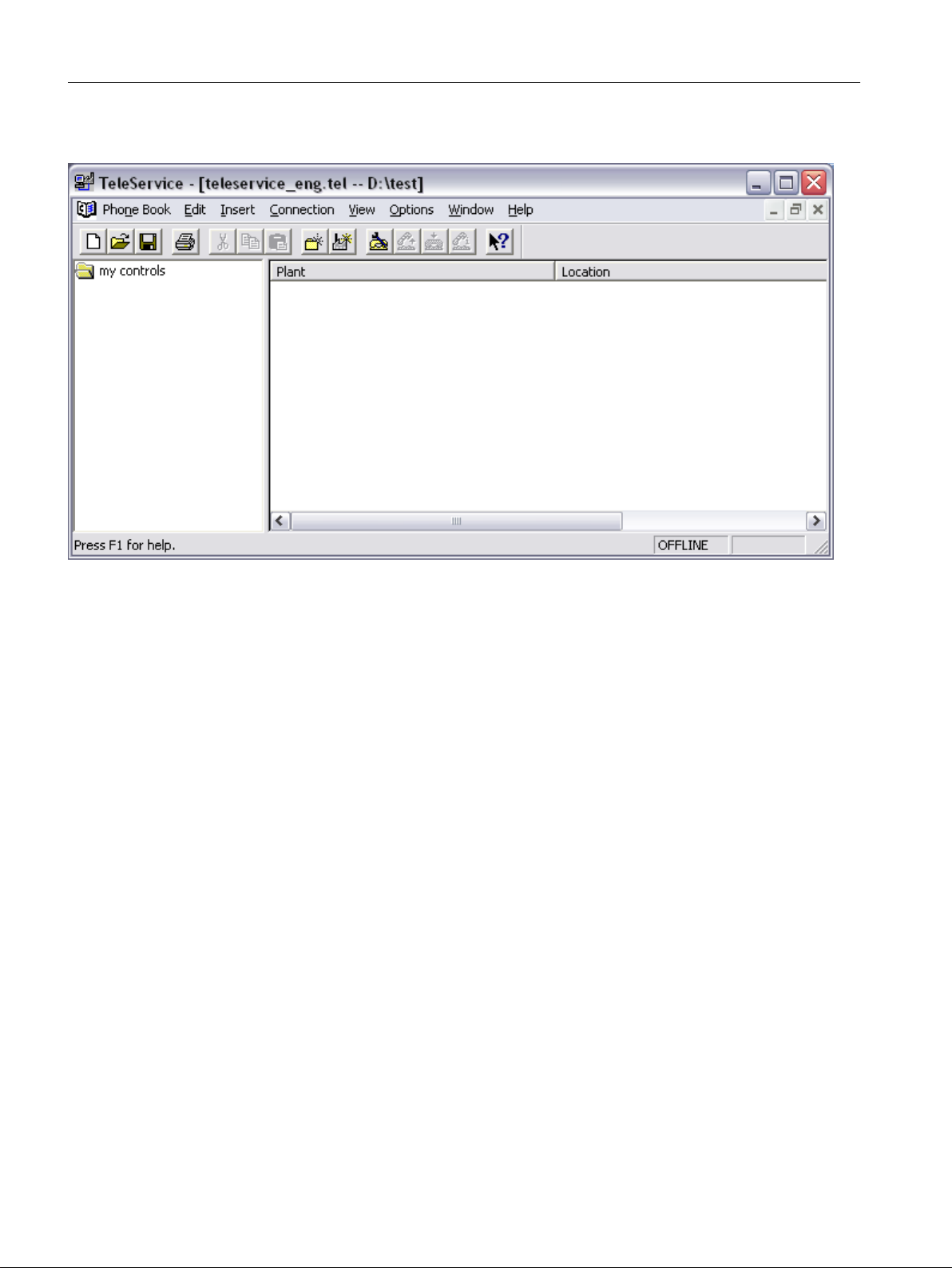
5.5.3.2 Inserting the system
Operating sequence
1. Start the "TeleService" Software.
2. Close all internal windows and select "Phone book" > "New".
3. Call it "newphonebook.tel".
4. Press <F3>.
A new folder is created.
SINUMERIK Integrate Access MyMachine /P2P (PC)
Operating Manual, 11/2016, A5E39356962B AA 39
Page 40
Connection to the control
5.5 Establishing a modem connection
5. Call it "my control systems".
Figure 5-8 TeleService
SINUMERIK Integrate Access MyMachine /P2P (PC)
40 Operating Manual, 11/2016, A5E39356962B AA
Page 41

6. Press <F4>.
A new system is inserted.
Connection to the control
5.5 Establishing a modem connection
Figure 5-9 Inserting a new system
SINUMERIK Integrate Access MyMachine /P2P (PC)
Operating Manual, 11/2016, A5E39356962B AA 41
Page 42

Connection to the control
5.5 Establishing a modem connection
7. Enter the data for the system (see figure for an example).
– Enter "840D sl" as the name and select "TS Adapter IE" as the adapter type.
– Enter the telephone number for contacting the TS Adapter as the number.
– The log-on data must specify a user created in the TS Adapter.
You can leave these fields empty at this point or enter "Administrator" + "admin" as the
default user.
8. Select "OK".
The application should now resemble the figure below.
Figure 5-10 System after insertion
You will now assign parameters for the TS Adapter.
See also
Assigning parameters for the TS Adapter (Page 43)
SINUMERIK Integrate Access MyMachine /P2P (PC)
42 Operating Manual, 11/2016, A5E39356962B AA
Page 43

5.5.3.3 Assigning parameters for the TS Adapter
Operating sequence
1. In the PG/PC interface, set the access point you wish to use when connecting to the
TS Adapter. In this instance, we are using a network connection to the PC via USB.
2. Select "Options" > "Settings".
The following dialog appears.
Connection to the control
5.5 Establishing a modem connection
Figure 5-11 Settings
3. Set the network connection to connect you with the TS Adapter directly.
SINUMERIK Integrate Access MyMachine /P2P (PC)
Operating Manual, 11/2016, A5E39356962B AA 43
Page 44
Connection to the control
5.5 Establishing a modem connection
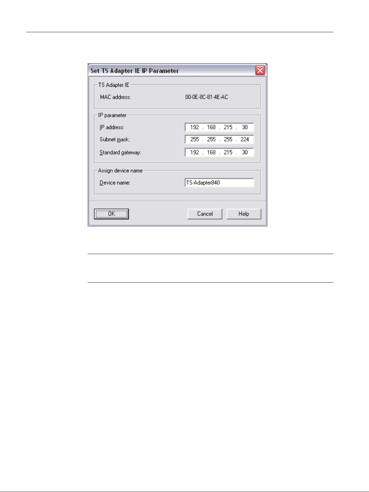
4. Select "Options" > "Set TS Adapter IE IP Parameter...".
See also
Figure 5-12 Setting parameters
5. Compare the MAC address with the MAC address printed on the TS Adapter.
Note
If the MAC addresses are different, select "Options" > "Settings". Now select the appropriate
TS Adapter in the "Settings" dialog.
6. Make the settings shown in the "Setting parameters" figure.
Make sure the TS Adapter and the control system are in the same subnet.
7. Select "OK".
You will now administrate the TS Adapter IE.
Administrating the TS Adapter (Page 45)
SINUMERIK Integrate Access MyMachine /P2P (PC)
44 Operating Manual, 11/2016, A5E39356962B AA
Page 45

5.5.3.4 Administrating the TS Adapter
Operating sequence
1. Select "Options" > "Administrate TS Adapter IE" in the "TeleService" software menu.
The following window appears.
Connection to the control
5.5 Establishing a modem connection
Figure 5-13 Administrate TS Adapter IE
2. Log on by entering "Administrator" and "admin" in the top-left section of the window.
SINUMERIK Integrate Access MyMachine /P2P (PC)
Operating Manual, 11/2016, A5E39356962B AA 45
Page 46

Connection to the control
5.5 Establishing a modem connection
3. Generate at least one additional user in the "Security" > "User administration" window (see
figure below) and assign admin rights to this user.
Example: "Siemens" + "siemens"
This user will be required again later and used to establish the connection to the TS Adapter.
Note
Delete the default user for security purposes.
Figure 5-14 User administration
SINUMERIK Integrate Access MyMachine /P2P (PC)
46 Operating Manual, 11/2016, A5E39356962B AA
Page 47

Connection to the control
5.5 Establishing a modem connection
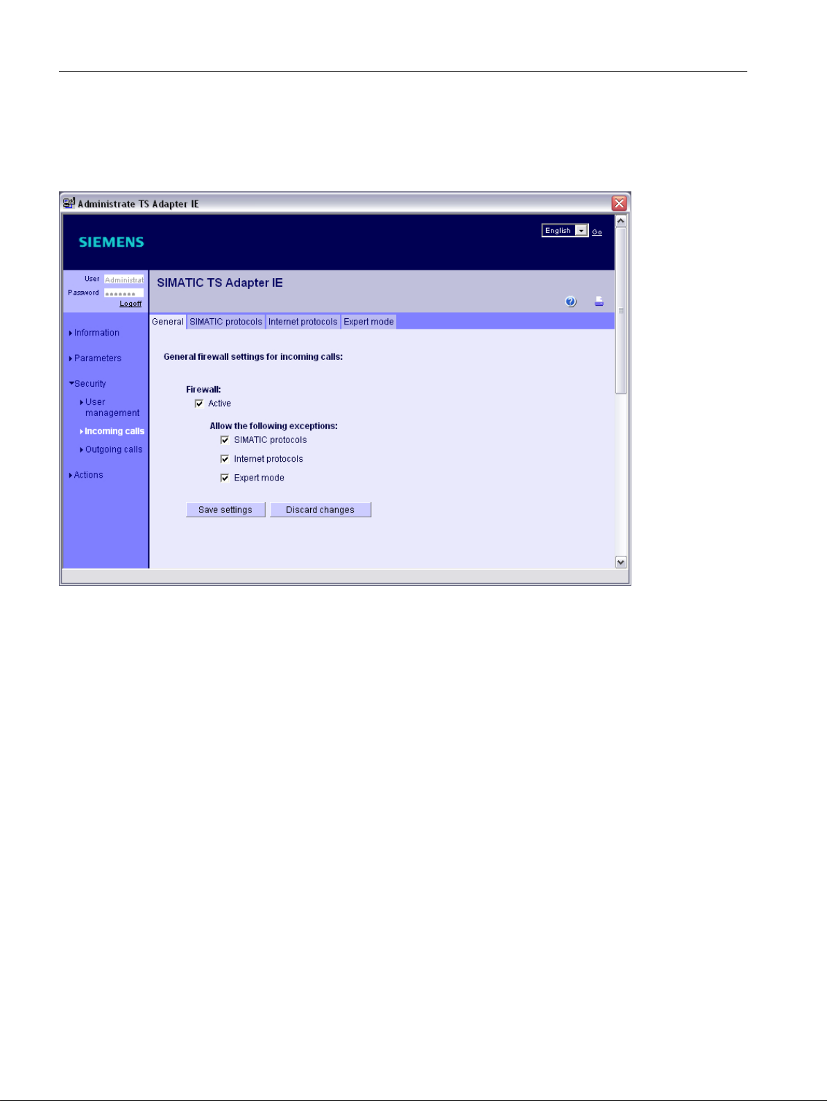
4. Activate the following (see figure below) for the TS Adapter on the "General" tab in the
"Security" > "Incoming calls" window:
– "Firewall"
SINUMERIK Integrate Access MyMachine /P2P (PC)
Operating Manual, 11/2016, A5E39356962B AA 47
Page 48
Connection to the control
5.5 Establishing a modem connection
– "Allow the following exceptions"
"Expert mode"
The "expert mode" function is used subsequently to enable the port for the VNC
connection.
Figure 5-15 "Security" > "Incoming calls" > "General" tab
SINUMERIK Integrate Access MyMachine /P2P (PC)
48 Operating Manual, 11/2016, A5E39356962B AA
Page 49

Connection to the control
5.5 Establishing a modem connection
Figure 5-16 "Security" > "Incoming calls" > "SIMATIC protocols" tab
SINUMERIK Integrate Access MyMachine /P2P (PC)
Operating Manual, 11/2016, A5E39356962B AA 49
Page 50
Connection to the control
5.5 Establishing a modem connection
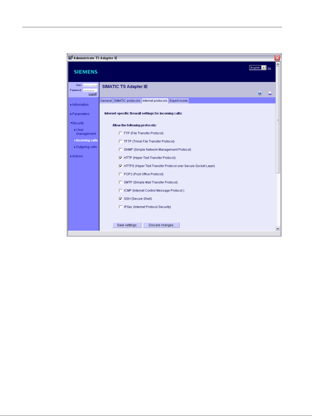
5. It is important that SSH is approved (see figure below).
Figure 5-17 "Security" > "Incoming calls" > "Internet protocols" tab
6. As already mentioned, VNC still requires approval. This is done in expert mode.
Port 5900 for VNC must be opened (see figure below).
SINUMERIK Integrate Access MyMachine /P2P (PC)
50 Operating Manual, 11/2016, A5E39356962B AA
Page 51

Connection to the control
5.5 Establishing a modem connection
See also
Figure 5-18 "Security" > "Incoming calls" > "Expert mode" tab
Note
Make the same settings for "outgoing calls".
You will now assign parameters for the internal modem of the TS Adapter IE.
Assigning parameters for the internal modem (Page 52)
SINUMERIK Integrate Access MyMachine /P2P (PC)
Operating Manual, 11/2016, A5E39356962B AA 51
Page 52
Connection to the control
5.5 Establishing a modem connection
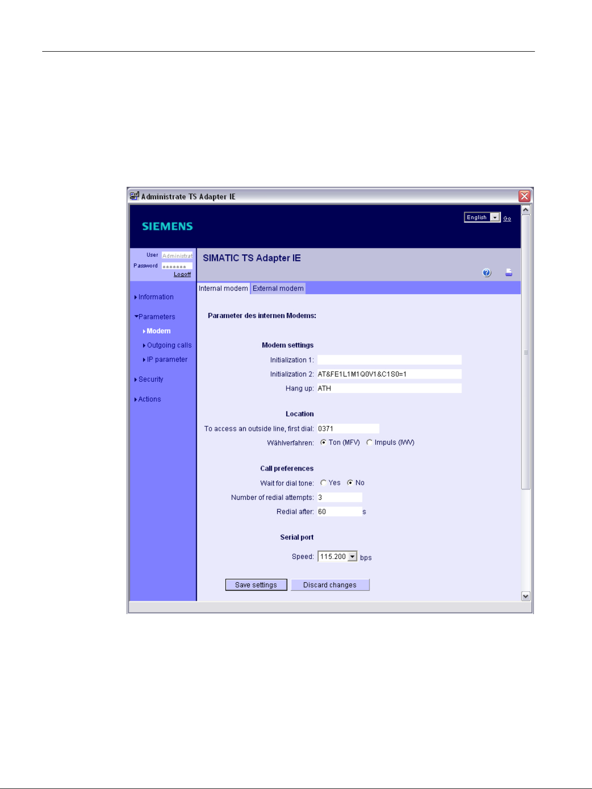
5.5.3.5 Assigning parameters for the internal modem
Operating sequence
1. Select "Options" > "Administrate TS Adapter IE" in the "TeleService" software menu.
2. Assign the parameters for the internal modem as shown.
If you are using an external modem, you will have to make the appropriate settings there.
Figure 5-19 "Parameters" > "Modem" > "Internal modem" tab
3. Enter the external access code which applies to you.
SINUMERIK Integrate Access MyMachine /P2P (PC)
52 Operating Manual, 11/2016, A5E39356962B AA
Page 53

Connection to the control
5.5 Establishing a modem connection
4. Check the IP parameters you set earlier with the TeleService software.
Figure 5-20 "Parameters" > "IP parameters"
SINUMERIK Integrate Access MyMachine /P2P (PC)
Operating Manual, 11/2016, A5E39356962B AA 53
Page 54

Connection to the control
5.5 Establishing a modem connection
5. To finish, reenter the contact telephone number for your modem on the PC.
Figure 5-21 "Parameters" > "Outgoing calls"
6. Close the window.
You will now test the connection which has been set.
See also
Testing the connection (Page 54)
5.5.3.6 Testing the connection
Operating sequence
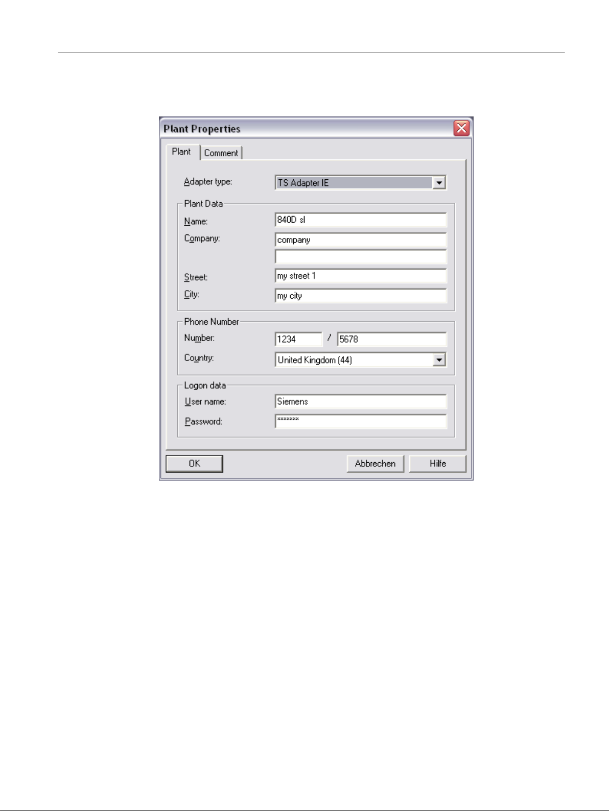
1. Right-click to access "Object properties..." via the shortcut menu.
2. Select the object properties of the "840D sl" system created previously (see figure below).
SINUMERIK Integrate Access MyMachine /P2P (PC)
54 Operating Manual, 11/2016, A5E39356962B AA
Page 55
Connection to the control
5.5 Establishing a modem connection
3. Enter the data for the user you have just created as the log-on data (e.g. "Siemens" +
"siemens").
Figure 5-22 "Insert new system" > "Log-on data"
SINUMERIK Integrate Access MyMachine /P2P (PC)
Operating Manual, 11/2016, A5E39356962B AA 55
Page 56

Connection to the control
5.5 Establishing a modem connection
4. You can now test the connection you have set. To do this, select the system and choose
"Establish" in the "Connection" menu (<F7> button).
Figure 5-23 "Establish connection"
SINUMERIK Integrate Access MyMachine /P2P (PC)
56 Operating Manual, 11/2016, A5E39356962B AA
Page 57

Connection to the control
5.5 Establishing a modem connection
5. Choose the modem and location and click "Select".
If connection is successful, the "ONLINE" field in the status bar will become green.
Figure 5-24 "ONLINE" system connection
SINUMERIK Integrate Access MyMachine /P2P (PC)
Operating Manual, 11/2016, A5E39356962B AA 57
Page 58

Connection to the control
5.5 Establishing a modem connection
6. Select "Connection" > "Current connection" to observe the status of the connection currently
established (see figure).
Figure 5-25 Current connection
7. Parameter assignment for your TS Adapter is now complete.
Make the following changes to the cabling (Page 60).
Connect the control system for X127 with the TS Adapter.
The PC should be already connected with the modem cable and the TS Adapter with the
other modem cable.
SINUMERIK Integrate Access MyMachine /P2P (PC)
58 Operating Manual, 11/2016, A5E39356962B AA
Page 59

'VO
7&8
1&8
7HOH6HUYLFH$GDSWHU,(
,QWHUDFWLRQ
(WKHUQHWFRQQHFWLRQ
*HQHUDOWHOHSKRQH
QHWZRUN
;
WHUPLQDO
;
WHUPLQDO
;
WHUPLQDO
/RFDO3&
NPRGHPFRQQHFWLRQ
NPR
GHP
FR
QQHFW
LRQ
Connection to the control
5.5 Establishing a modem connection
Figure 5-26 Modem connection from the PC to the control system via the network and the TeleService Adapter IE
See also
Establishing a connection/Cabling (Page 60)
5.5.4 Parameterize the TeleService adapter IE without the "TeleService" software
Operating sequence
1. Item 7.16 (Reset parametrization with the P RES button) (see Help for TS adapters).
2. Modem selection (long-distance data transmission network), (see Create modem
connection under Windows 7 (Page 62) and Establish modem connection under Windows
7 (Page 67)).
IP address 192.168.0.2 or 192.168.0.3 is assigned.
3. Start Internet browser and link up with http://192.168.0.1.
4. Log in with user Administrator and Password admin.
SINUMERIK Integrate Access MyMachine /P2P (PC)
Operating Manual, 11/2016, A5E39356962B AA 59
Page 60

Connection to the control
5.5 Establishing a modem connection
5. Enter IP parameter as described as from Assigning parameters for the TS Adapter
(Page 43) Step 4.
6. Continue through the following steps:
– see Administrating the TS Adapter (Page 45)
– see Assigning parameters for the internal modem (Page 52)
– see Establishing a connection/Cabling (Page 60)right through to Connecting AMM to
the control system via the modem connection (Page 75)
See also
Create modem connection under Windows 7 (Page 62)
Establish modem connection under Windows 7 (Page 67)
Assigning parameters for the TS Adapter (Page 43)
Administrating the TS Adapter (Page 45)
Assigning parameters for the internal modem (Page 52)
Establishing a connection/Cabling (Page 60)
Connecting AMM to the control system via the modem connection (Page 75)
5.5.5 Establishing a connection/Cabling
Components
You will need the following components:
● Two modem terminals in the general telephone network for the following components:
– PC
– TeleService adapter IE
● PC with 56k modem
● TeleService adapter IE
● Ethernet cable
● Control system (840D sl with NCU 720.1 in this example)
Requirement
You need to have assigned parameters (Page 38) for the TeleService adapter IE.
SINUMERIK Integrate Access MyMachine /P2P (PC)
60 Operating Manual, 11/2016, A5E39356962B AA
Page 61

Establishing a modem connection via the general telephone network
'VO
7&8
1&8
7HOH6HUYLFH$GDSWHU,(
,QWHUDFWLRQ
(WKHUQHWFRQQHFWLRQ
*HQHUDOWHOHSKRQH
QHWZRUN
;
WHUPLQDO
;
WHUPLQDO
;
WHUPLQDO
/RFDO3&
NPRGHPFRQQHFWLRQ
NPR
GHP
FR
QQHFW
LRQ
Set up the network via the modem terminals as follows (please also refer to the figure below):
1. Connect the PC with the general telephone network via the modem terminal.
2. Connect the TS adapter with the general telephone network via the modem terminal.
3. Connect the TS adapter with the control system's X127 interface via the Ethernet interface.
Use an Ethernet cable for this purpose.
There is no need to integrate the TS adapter into the system network/workplace network,
as the control system operates its own DHCP server on the X127 interface.
The TS adapter is automatically assigned an IP address from this X127 interface.
Note
The control system is still accessible via the X130 interface, for example.
Connection to the control
5.5 Establishing a modem connection
Figure 5-27 Modem connection from the PC to the control system via the network and the TeleService adapter IE
See also
Parameterize the TeleService adapter IE with the "TeleService" software (Page 38)
SINUMERIK Integrate Access MyMachine /P2P (PC)
Operating Manual, 11/2016, A5E39356962B AA 61
Page 62

Connection to the control
5.5 Establishing a modem connection
5.5.6 Create modem connection under Windows 7
Operating sequence
1. Select "Start > Control Panel > Network and Sharing Center > Set up a new connection or
network".
2. Select the connection option "Connect to a workplace".
Figure 5-28 Connect to a workplace
3. Press "Next".
SINUMERIK Integrate Access MyMachine /P2P (PC)
62 Operating Manual, 11/2016, A5E39356962B AA
Page 63

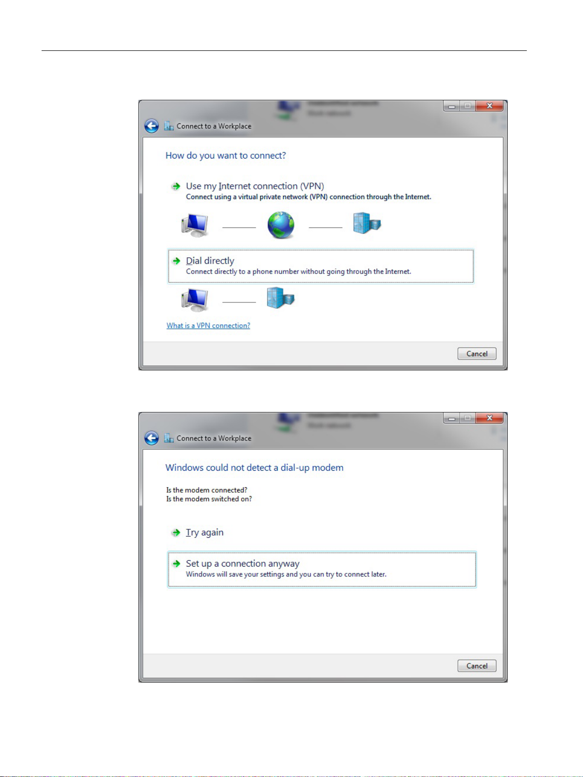
4. Select "Dial directly".
Connection to the control
5.5 Establishing a modem connection
Figure 5-29 Dial directly
5. Press "Set up a connection anyway". Connect a modem later if no modem is connected.
Figure 5-30 Set up a connection anyway
SINUMERIK Integrate Access MyMachine /P2P (PC)
Operating Manual, 11/2016, A5E39356962B AA 63
Page 64
Connection to the control
5.5 Establishing a modem connection
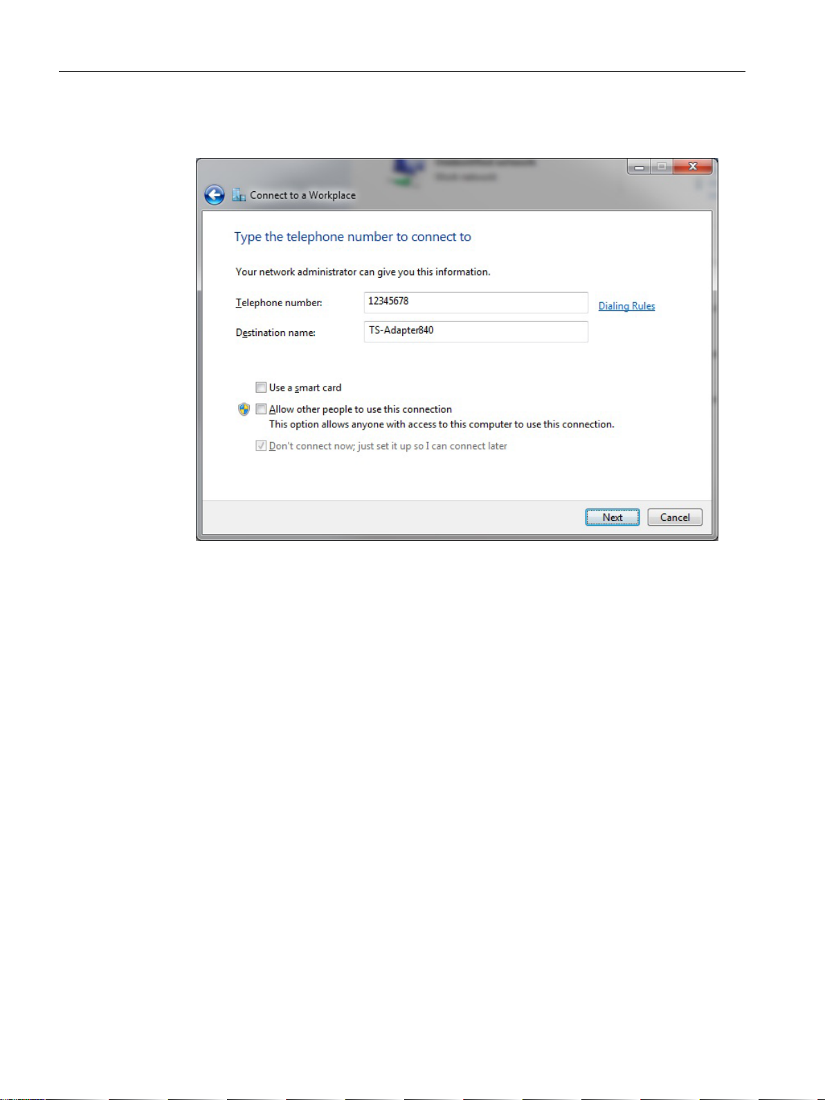
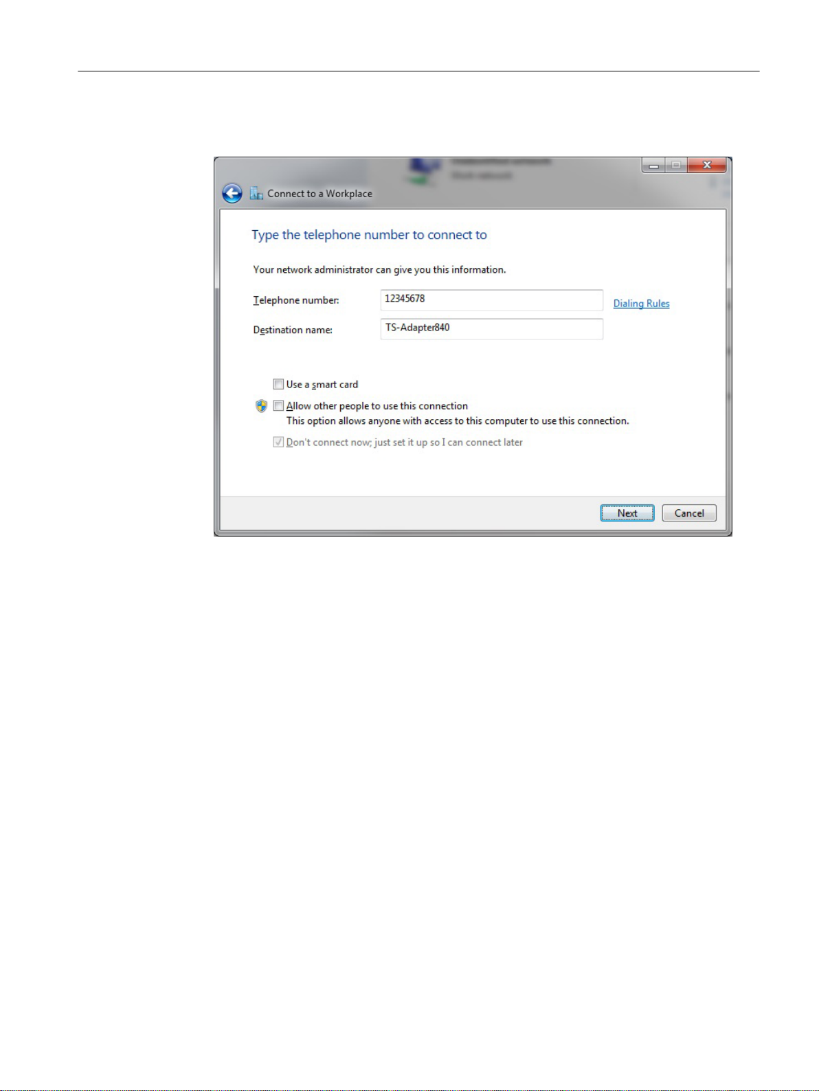
6. Enter the telephone number for contacting your TS adapter and assign a name to the
connection.
Figure 5-31 Enter telephone number
7. Press "Next".
SINUMERIK Integrate Access MyMachine /P2P (PC)
64 Operating Manual, 11/2016, A5E39356962B AA
Page 65

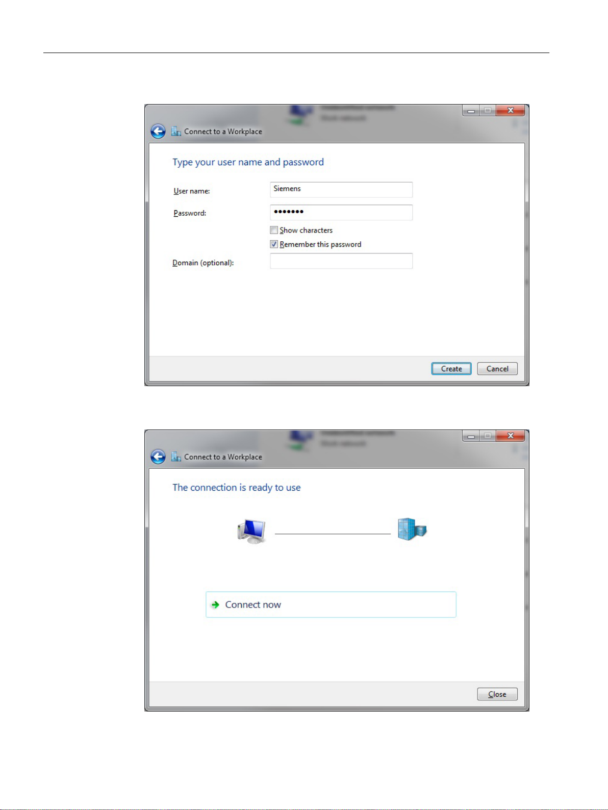
8. Enter the user name and password of the TS adapter.
Connection to the control
5.5 Establishing a modem connection
Figure 5-32 Enter user name and password:
9. Press "Create".
Figure 5-33 Establish connection
SINUMERIK Integrate Access MyMachine /P2P (PC)
Operating Manual, 11/2016, A5E39356962B AA 65
Page 66

Connection to the control
5.5 Establishing a modem connection
Connection successfully established You can close the dialog or establish a connection.
SINUMERIK Integrate Access MyMachine /P2P (PC)
66 Operating Manual, 11/2016, A5E39356962B AA
Page 67
5.5.7 Establish modem connection under Windows 7
Operating sequence
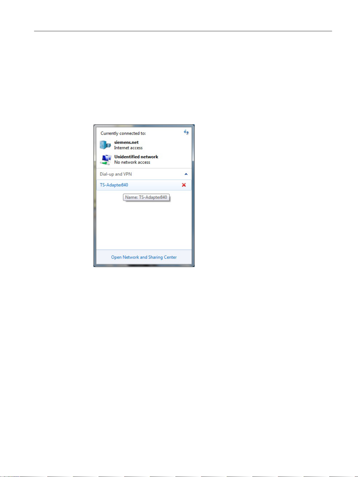
Establish a connection to your TS adapter as follows.
1. In Windows, select "Start > Control panel > Network and sharing center > Connect to a
network".
2. Click the dial-up connection with the name you have assigned.
Connection to the control
5.5 Establishing a modem connection
Figure 5-34 Select modem connection
3. Press "Connect".
SINUMERIK Integrate Access MyMachine /P2P (PC)
Operating Manual, 11/2016, A5E39356962B AA 67
Page 68

Connection to the control
5.5 Establishing a modem connection
Figure 5-35 Connecting
A connection is established to the TS adapter.
SINUMERIK Integrate Access MyMachine /P2P (PC)
68 Operating Manual, 11/2016, A5E39356962B AA
Page 69

5.5.8 Create a modem connection under Windows 10
Operating sequence
1. Select Start > Settings > Network and Internet > Dial-up > Set up a new connection".
2. Select the connection option "Connect to a workplace".
Connection to the control
5.5 Establishing a modem connection
Figure 5-36 Connect to a workplace
3. Press "Next".
SINUMERIK Integrate Access MyMachine /P2P (PC)
Operating Manual, 11/2016, A5E39356962B AA 69
Page 70
Connection to the control
5.5 Establishing a modem connection
4. Select "Dial directly".
Figure 5-37 Dial directly
5. Press "Set up a connection anyway". Connect a modem later if no modem is connected.
Figure 5-38 Set up a connection anyway
SINUMERIK Integrate Access MyMachine /P2P (PC)
70 Operating Manual, 11/2016, A5E39356962B AA
Page 71
Connection to the control
5.5 Establishing a modem connection
6. Enter the telephone number for contacting your TS adapter and assign a name to the
connection.
Figure 5-39 Enter telephone number
7. Press "Next".
SINUMERIK Integrate Access MyMachine /P2P (PC)
Operating Manual, 11/2016, A5E39356962B AA 71
Page 72
Connection to the control
5.5 Establishing a modem connection
8. Enter the user name and password of the TS adapter.
Figure 5-40 Enter user name and password:
9. Press "Create".
Figure 5-41 Establish connection
SINUMERIK Integrate Access MyMachine /P2P (PC)
72 Operating Manual, 11/2016, A5E39356962B AA
Page 73

Connection to the control
5.5 Establishing a modem connection
Connection successfully established You can close the dialog or establish a connection.
SINUMERIK Integrate Access MyMachine /P2P (PC)
Operating Manual, 11/2016, A5E39356962B AA 73
Page 74

Connection to the control
5.5 Establishing a modem connection
5.5.9 Establish a modem connection under Windows 10
Operating sequence
Establish a connection to your TS adapter as follows.
1. In Windows, select "Start > Settings > Network and Internet > Dial-up".
2. Click the dial-up connection with the name you have assigned.
Figure 5-42 Dial up - select modem connection
3. Press "Connect".
SINUMERIK Integrate Access MyMachine /P2P (PC)
74 Operating Manual, 11/2016, A5E39356962B AA
Page 75

Connection to the control
5.5 Establishing a modem connection
Figure 5-43 Dial up - establish connection
A connection is established to the TS adapter.
5.5.10 Connecting AMM to the control system via the modem connection
Operating sequence
1. Establish a modem connection (Page 67) to your TS adapter.
2. Next, start AMM and select the direct connection (see Establishing the connection
(Page 31)). Enter the authentication data you wish to use when logging onto the control
system. This is not the same data you entered for the TS adapter.
3. Once you have established the connection, you can copy files in either direction and operate
the control system remotely.
Note
When making the settings for the connection used (direct connection or network
connection) in AMM, you should set the "Transmission type" to transmission rate "Low". If
you do not do this, you may not be able to operate the control remotely, and the connection
may suffer from frequent interruptions.
This setting only applies to remote control: it does not apply to file transfers.
See also
Establishing the connection (Page 31)
Establish modem connection under Windows 7 (Page 67)
SINUMERIK Integrate Access MyMachine /P2P (PC)
Operating Manual, 11/2016, A5E39356962B AA 75
Page 76

Connection to the control
5.5 Establishing a modem connection
5.5.11 Further information
For more detailed information on parameter assignment for the TS Adapter, please refer to
the supplementary material provided ("TS Adapter IE – Handbuch.pdf") or the following online
sources:
Product Support (http://support.automation.siemens.com/WW/view/de/10805406/130000)
TeleService Adapter Manual (http://support.automation.siemens.com/WW/view/de/
24623021)
SINUMERIK Integrate Access MyMachine /P2P (PC)
76 Operating Manual, 11/2016, A5E39356962B AA
Page 77

Operator control (software)
6.1 Remote control of the control system
6.1.1 Overview of remote control
With the "remote control" function you can:
● Monitor and operate the control from the PG/PC (remotely).
● Generate screenshots of the control's HMI, and save them to the PG/PC. This enables you
to inform support personnel of errors in the control's HMI via screenshots.
Software option
The "SINUMERIK Integrate Access MyMachine /P2P (PC) (6FC5800-0AP30-0YB0)" option is required for
remote access via TeleService Adapter.
See also
Starting/ending remote control (Page 82)
6
Using remote control to generate the screen of the control system's HMI user interface
(Page 87)
SINUMERIK Integrate Access MyMachine /P2P (PC)
Operating Manual, 11/2016, A5E39356962B AA 77
Page 78

Operator control (software)
6.1 Remote control of the control system
6.1.2 Approving remote control of the control system on the HMI
6.1.2.1 Approving remote control on the HMI
Operating sequence for 840D sl/828D controls
1. Press the "Remote diagnostics" softkey in the "Diagnosis" operating area.
Figure 6-1 "Remote diagnostics" on the HMI
2. The following settings can be made:
– Remote access rights
SINUMERIK Integrate Access MyMachine /P2P (PC)
78 Operating Manual, 11/2016, A5E39356962B AA
Page 79

– Procedure for confirming remote access
Operator control (software)
6.1 Remote control of the control system
Figure 6-2 Observing "remote diagnostics" on the HMI
3. Choose the appropriate remote access function in the selection box.
Operating sequence for an 808D control
1. Press the "remote diag" softkey to make the settings.
2. The following settings can be made:
– Remote access rights
– Procedure for confirming remote access
Figure 6-3 Enable remote control of 808D
SINUMERIK Integrate Access MyMachine /P2P (PC)
Operating Manual, 11/2016, A5E39356962B AA 79
Page 80

Operator control (software)
6.1 Remote control of the control system
3. Confirm the selected setting with the "Select" softkey to enable remote access.
4. Confirm the settings made with the "Activate" softkey.
SINUMERIK Integrate Access MyMachine /P2P (PC)
80 Operating Manual, 11/2016, A5E39356962B AA
Page 81

6.1.2.2 Approving remote control via the control system
Operating sequence
1. If remote control is used to connect a PC with the control, the following dialog opens on the
HMI:
Operator control (software)
6.1 Remote control of the control system
Figure 6-4 Allowing remote control
2. You can refuse ("No") or permit ("Yes") control from the external PC.
If you fail to provide any acknowledgement, the dialog closes automatically after a defined
period of time.
Depending on the setting, remote control can be refused or permitted automatically (see
Approving remote control on the HMI (Page 78)).
Note
Automatic connection should not be permitted for security reasons.
A more secure method involves an on-site operator pressing the "Yes" softkey on the control
to allow remote control.
SINUMERIK Integrate Access MyMachine /P2P (PC)
Operating Manual, 11/2016, A5E39356962B AA 81
Page 82

Operator control (software)
6.1 Remote control of the control system
Where permission has been granted, the control can be operated and monitored remotely.
6.1.2.3 Further documentation
References
The following SINUMERIK manuals contain further information:
● SINUMERIK Operate Commissioning Manual
● 808D Commissioning Manual
● Turning, milling, and grinding operating manuals
SINUMERIK support documentation (http://support.automation.siemens.com/WW/view/de/
10805517/130000)
6.1.3 Functional scope of the remote control
NOTICE
Insecure use of the function to transfer files
The VNC protocol used for remote control provides an option as standard for the transfer of
files. This function is not activated per default in the control for security reasons and therefore
cannot be used in AMM.
In contrast to the VNC function, the file transfer in AMM uses the SSH protocol with secure
data encryption. Use the appropriate function in AMM for the file transfer to and from the
control. This applies in particular when the remote control is via networks.
6.1.3.1 Starting/ending remote control
Operating sequence
1. Establish a connection to a SINUMERIK solution line control (see "Establishing a
connection to the control" (Page 21)).
2. To start/end the "remote control", click "Remote control" in the main window menu or click
the "Remote control" button in the toolbar.
SINUMERIK Integrate Access MyMachine /P2P (PC)
82 Operating Manual, 11/2016, A5E39356962B AA
Page 83

Operator control (software)
6.1 Remote control of the control system
3. Once remote control has been started, a new window opens showing the screen contents
of the connected control.
Figure 6-5 Remote control of the control
4. While the remote control function is open, you can continue operating AMM as usual.
SINUMERIK Integrate Access MyMachine /P2P (PC)
Operating Manual, 11/2016, A5E39356962B AA 83
Page 84

Operator control (software)
6.1 Remote control of the control system
Figure 6-6 AMM and remote-controlled control on the PG/PC
See also
Establishing a connection to the control system: An overview (Page 21)
Overview of remote control (Page 77)
SINUMERIK Integrate Access MyMachine /P2P (PC)
84 Operating Manual, 11/2016, A5E39356962B AA
Page 85

6.1.3.2 Operation
Using remote control to operate the control system's user interface
If you have used "remote control" to connect to the control system, you will have the following
options for operating the user interface from the PG/PC:
1. Mouse
2. Keyboard
Operator control (software)
6.1 Remote control of the control system
Figure 6-7 Remote control of the control system
Mouse operation
● You can click the softkeys to operate them.
● The symbol for the operating areas is displayed in the top-left corner of the user interface.
● With SINUMERIK 840D sl and 828D click the symbol to display the operating areas on the
horizontal softkey bar.
SINUMERIK Integrate Access MyMachine /P2P (PC)
Operating Manual, 11/2016, A5E39356962B AA 85
Page 86

Operator control (software)
6.1 Remote control of the control system
Keyboard operation
● Press F1 to F8 on the keyboard to operate the horizontal softkeys.
● Press Shift+F1 to Shift+F8 on the keyboard to operate the vertical softkeys.
● With SINUMERIK 840D sl and 828D press F10 on the keyboard to display the operating
areas on the horizontal softkey bar.
● With SINUMERIK 808D, press Alt+X to Alt+N on the keyboard to switch between the
operating areas.
SINUMERIK Integrate Access MyMachine /P2P (PC)
86 Operating Manual, 11/2016, A5E39356962B AA
Page 87

Operator control (software)
6.1 Remote control of the control system
6.1.3.3 Using remote control to generate the screen of the control system's HMI user interface
Operating sequence
1. Establish a connection to a SINUMERIK solution line control (see "Establishing a
connection to the control" (Page 21)).
2. To start "remote control", click "Remote control" in the main window menu or use the
"Remote control"
A window opens showing the HMI user interface on the PG/PC.
button in the toolbar.
Figure 6-8 Remote control of the control
3. Click "Remote control" -> "Save as screen dump" in the main window menu.
4. You can save the current image of the control's HMI user interface to the PG/PC as a png
or bmp file.
SINUMERIK Integrate Access MyMachine /P2P (PC)
Operating Manual, 11/2016, A5E39356962B AA 87
Page 88

Operator control (software)
6.1 Remote control of the control system
See also
Establishing a connection to the control system: An overview (Page 21)
Overview of remote control (Page 77)
SINUMERIK Integrate Access MyMachine /P2P (PC)
88 Operating Manual, 11/2016, A5E39356962B AA
Page 89

6.2 Project
6.2.1 Project overview
Functionality
You can edit various user files of a control configuration offline with the aid of a project. In this
way, you can bring together logically related files of a control (e.g. for machine-specific
administration of the user data for commissioning on the manufacturer's premises). A project
always depends on the type of control.
You can manage a project using the following functions:
● Create a project (OFFLINE)
● Create a project and read the files from the control (ONLINE)
● Open an existing project
● Close a project
Operator control (software)
6.2 Project
● Delete a project
● Create a new language
● Edit individual languages
● Add files
● Delete files
● Edit files:
● Import/export files: Support for translation processes
● Transfer individual files from the project to the control system
● Transfer individual files from the control system to the project
● Delete the files on the control using the project dialog
SINUMERIK Integrate Access MyMachine /P2P (PC)
Operating Manual, 11/2016, A5E39356962B AA 89
Page 90

Operator control (software)
6.2 Project
Structure of a project
A project always basically consists of a *.rcsproj file and an associated directory structure. The
associated directories and files stand under each other in a logical relation. A subset of the file
system of the control is normally shown in the offline project. You will find those files that are
supported by the AMM in chapter Supported files (Page 149).
Note
Damage to the project
Note that manual modification to the directory structure of the project may damage it.
Compatibility
A project has its own version ID. This version ID is used for the compatibility. AMM can always
load older projects, but always saves them in the latest project format. Old AMM versions may
not be able to load newer projects.
Project information
See also
Select a *.rcsproj file in the file manager of the AMM, and click "Properties" in the shortcut
menu. The following project information is displayed:
● Control system type
● Name
● Path
● Version
● Creation date
● Files
Create a project and read the files from the control system (ONLINE) (Page 92)
Opening an existing project (Page 95)
Closing the project (Page 99)
Deleting a project (Page 100)
Creating a new language (Page 101)
Adding a file (Page 103)
Deleting a file (Page 105)
Exporting a file (Page 106)
Import file (Page 109)
Edit file (Page 111)
Transferring individual files from the project to the control system (Page 115)
SINUMERIK Integrate Access MyMachine /P2P (PC)
90 Operating Manual, 11/2016, A5E39356962B AA
Page 91
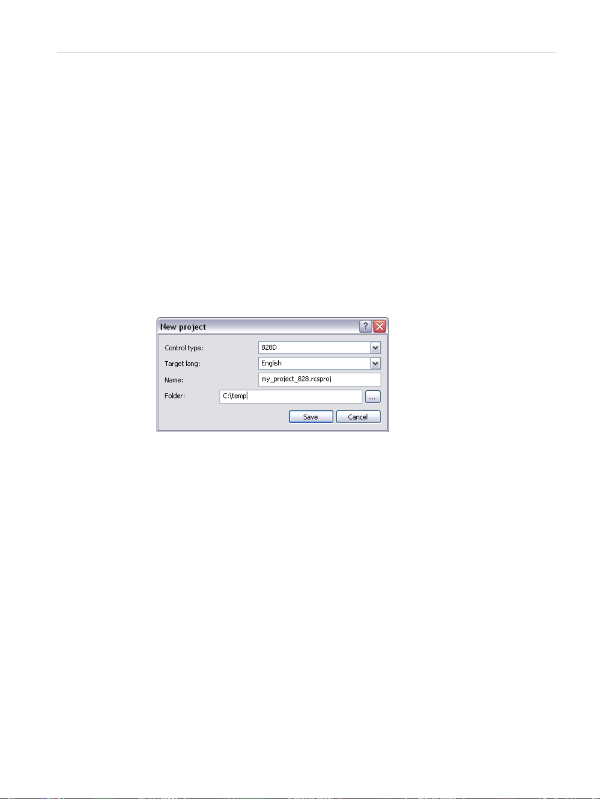
Transferring individual files from the control to the project (Page 119)
Deleting files on the control using the project dialog (Page 121)
Recommended procedure when translating files (Page 124)
Activating the alarm text files on the control using an HMI restart (Page 126)
6.2.2 Creating a project (OFFLINE)
This function generates a new project on the PG/PC for a specific control type. A freely chosen
project name and a file name has to be entered as the storage location on the PG/PC. A newly
created project always has at least one target language, in which the HMI texts (alarm texts,
tool management texts, etc.) can be edited. Further languages can be added and deleted later.
Operating sequence
1. To create a project, click "File" > "New" > "Project…" in the menu of the main window.
Operator control (software)
6.2 Project
Figure 6-9 New project
2. In the dialog, select the control type for which you want to create a project.
3. Select a target language in which the first user text files are to be created.
4. Enter a name for the project The extension is automatically added, and must be *.rcsproj.
SINUMERIK Integrate Access MyMachine /P2P (PC)
Operating Manual, 11/2016, A5E39356962B AA 91
Page 92

Operator control (software)
6.2 Project
5. Select the storage location of the project on the PC.
6. The project is created and opened in the project dialog with "Save".
If a project already exists, an error message appears.
Figure 6-10 Project dialog (OFFLINE)
6.2.3 Create a project and read the files from the control system (ONLINE)
Operating sequence
1. Establish a connection to a control system (see Connection to the control (Page 21)).
2. To create a project from the control, and automatically transfer all relevant files, select
"File > New > Read out project from machine" in the menu of the main window (this menu
item is only activated if a connection to a control has been established).
SINUMERIK Integrate Access MyMachine /P2P (PC)
92 Operating Manual, 11/2016, A5E39356962B AA
Page 93

Operator control (software)
6.2 Project
3. A dialog opens to create a new project.
Figure 6-11 New project
4. The control type is automatically preselected and cannot be changed.
5. Select a target language in which the first user text files are to be created. (If available on
the control system, they will be automatically overwritten in the project.)
6. Enter a name for the project (the extension is automatically added and must be *.rcsproj).
7. Select the storage location of the project on the PC.
SINUMERIK Integrate Access MyMachine /P2P (PC)
Operating Manual, 11/2016, A5E39356962B AA 93
Page 94

Operator control (software)
6.2 Project
8. The project is created with "Save".
9. The control system is then automatically read-out and the files that are found are transferred
into the project.
Figure 6-12 Copy
– Once the found files have been copied, then the new project is displayed in the project
dialog.
– If a project is already open, a prompt appears to query whether the new project should
be opened or the old project retained.
SINUMERIK Integrate Access MyMachine /P2P (PC)
94 Operating Manual, 11/2016, A5E39356962B AA
Page 95

Operator control (software)
6.2 Project
Figure 6-13 Project dialog (ONLINE)
6.2.4 Opening an existing project
Introduction
The following two options are available to open an existing project:
● Using the menu
● With a double-click on the project file
SINUMERIK Integrate Access MyMachine /P2P (PC)
Operating Manual, 11/2016, A5E39356962B AA 95
Page 96

Operator control (software)
6.2 Project
Operating sequence "Using the menu"
1. Select "File > Open project" from the menu.
2. The following dialog appears. The projects that were last opened are displayed in this dialog
and can be subsequently selected, whereby the last project that was opened is preselected.
Figure 6-14 Open project
3. Select a project that should be opened. If the required project is not listed for selection, you
can search for the project on the PC using "Search". In this case, a search is made for
project files with the extension (*.rcsproj).
SINUMERIK Integrate Access MyMachine /P2P (PC)
96 Operating Manual, 11/2016, A5E39356962B AA
Page 97

Operator control (software)
6.2 Project
4. After the desired project has been selected, it can be opened with "Open".
5. The opened project is then displayed in the project dialog. The name of the active, open
project appears at the top, in the title bar of the program.
Figure 6-15 Project dialog (OFFLINE)
SINUMERIK Integrate Access MyMachine /P2P (PC)
Operating Manual, 11/2016, A5E39356962B AA 97
Page 98

Operator control (software)
6.2 Project
Operator action "With a double-click on the project file"
1. Navigate in the file display of AMM to the storage location of the project to be opened.
Figure 6-16 AMM (OFFLINE and without project)
2. Open the project with Open from the shortcut menu or by double-clicking the *.rcsproj file.
3. The project is then displayed in the project dialog. The name of the active, open project
appears at the top, in the title bar of the program.
SINUMERIK Integrate Access MyMachine /P2P (PC)
98 Operating Manual, 11/2016, A5E39356962B AA
Page 99

Operator control (software)
6.2 Project
Figure 6-17 AMM with project dialog (OFFLINE)
6.2.5 Closing the project
Operating sequence
1. You can close the open project with "File > Close project" in the main window menu.
2. The project dialog disappears, and "No project active" is displayed in the title bar of AMM.
As a consequence, a project is not automatically opened the next time AMM starts.
Note
Show/hide project window
If you want to hide the project window without closing the project, deactivate the checkbox in
the menu "View > Project window". You can show the project window again in the same way.
SINUMERIK Integrate Access MyMachine /P2P (PC)
Operating Manual, 11/2016, A5E39356962B AA 99
Page 100
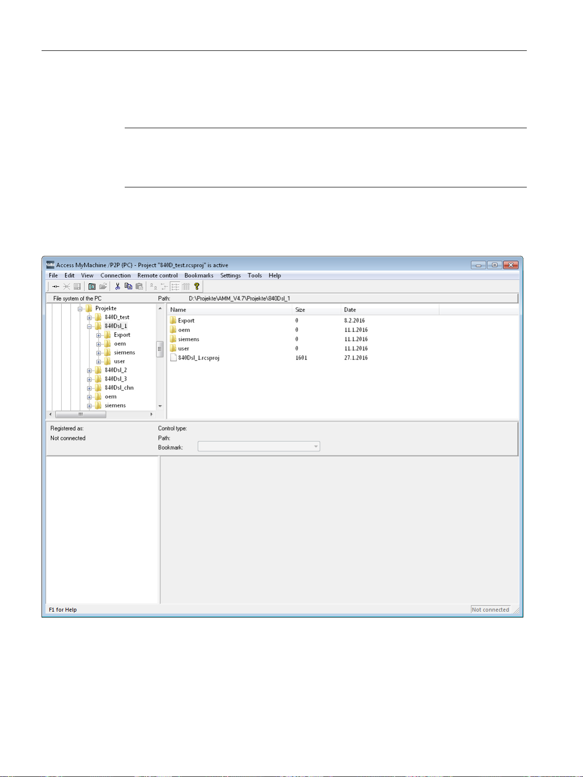
Operator control (software)
6.2 Project
6.2.6 Deleting a project
Note
Possible data loss
Note that files which you have copied into the project directory yourself are also deleted by the
delete process!
Operating sequence
1. Navigate in the file display of AMM to the storage location of the project to be deleted.
Figure 6-18 AMM (OFFLINE and without project)
The project was created in a directory which has the same name as the project. The project
file is located directly below (*.rcsproj).
2. Delete the complete directory with "Del" or with the "Delete" shortcut menu
SINUMERIK Integrate Access MyMachine /P2P (PC)
100 Operating Manual, 11/2016, A5E39356962B AA
 Loading...