

Siemens SINUMERIK 840D sl, SINUMERIK 840D sl OP 010, HT 8, SINUMERIK 840DE sl User Manual

SINUMERIK
SINUMERIK 840D sl
Operator panel front: OP 012
Valid for:
Control system
SINUMERIK 840D sl/840DE sl
General information and
networking
1
Manual
Description
Operator control and display
elements
Interfaces
Installation
Technical data
Spare parts
2
3
4
5
6
7
09/2016
A5E36371591B
Legal information
Warning notice system
This manual contains notices you have to observe in order to ensure your personal safety, as well as to prevent
damage to property. The notices referring to your personal safety are highlighted in the manual by a safety alert
symbol, notices referring only to property damage have no safety alert symbol. These notices shown below are
graded according to the degree of danger.
DANGER
indicates that death or severe personal injury will result if proper precautions are not taken.
WARNING
indicates that death or severe personal injury may result if proper precautions are not taken.
CAUTION
indicates that minor personal injury can result if proper precautions are not taken.
NOTICE
indicates that property damage can result if proper precautions are not taken.
If more than one degree of danger is present, the warning notice representing the highest degree of danger will be
used. A notice warning of injury to persons with a safety alert symbol may also include a warning relating to property
damage.
Qualified Personnel
The product/system described in this documentation may be operated only by personnel qualified for the specific
task in accordance with the relevant documentation, in particular its warning notices and safety instructions. Qualified
personnel are those who, based on their training and experience, are capable of identifying risks and avoiding
potential hazards when working with these products/systems.
Proper use of Siemens products
Note the following:
WARNING
Siemens products may only be used for the applications described in the catalog and in the relevant technical
documentation. If products and components from other manufacturers are used, these must be recommended or
approved by Siemens. Proper transport, storage, installation, assembly, commissioning, operation and
maintenance are required to ensure that the products operate safely and without any problems. The permissible
ambient conditions must be complied with. The information in the relevant documentation must be observed.
Trademarks
All names identified by ® are registered trademarks of Siemens AG. The remaining trademarks in this publication
may be trademarks whose use by third parties for their own purposes could violate the rights of the owner.
Disclaimer of Liability
We have reviewed the contents of this publication to ensure consistency with the hardware and software described.
Since variance cannot be precluded entirely, we cannot guarantee full consistency. However, the information in
this publication is reviewed regularly and any necessary corrections are included in subsequent editions.
Siemens AG
Division Digital Factory
Postfach 48 48
90026 NÜRNBERG
GERMANY
A5E36371591B
Ⓟ 09/2016 Subject to change
Copyright © Siemens AG 2007 - 2016.
All rights reserved

Table of contents
1 General information and networking.............................................................................................................5
1.1 Fundamental safety instructions..............................................................................................5
1.1.1 General safety instructions.......................................................................................................5
1.1.2 Handling electrostatic sensitive devices (ESD)........................................................................8
1.1.3 Industrial security.....................................................................................................................8
1.1.4 Residual risks of power drive systems...................................................................................10
1.2 Application planning...............................................................................................................11
1.2.1 Secondary electrical conditions..............................................................................................11
1.2.1.1 Power supply..........................................................................................................................11
1.2.1.2 Grounding concept.................................................................................................................12
1.2.1.3 EMC compatibility..................................................................................................................12
1.2.2 Ambient climatic and mechanical conditions..........................................................................14
1.2.2.1 Transport and storage conditions...........................................................................................14
1.2.2.2 Operating conditions..............................................................................................................16
1.2.2.3 Cooling...................................................................................................................................17
1.2.3 Standards and approvals.......................................................................................................20
1.2.4 Recycling and disposal..........................................................................................................21
1.3 Connecting.............................................................................................................................22
1.3.1 Pin assignment of the interfaces............................................................................................22
1.3.2 Handling membrane connectors............................................................................................36
1.4 Networking.............................................................................................................................36
1.4.1 System settings......................................................................................................................36
1.4.1.1 Settings for SINUMERIK solution line....................................................................................36
1.4.1.2 System boot with system network..........................................................................................38
1.4.1.3 Thin Client Unit (TCU)............................................................................................................39
1.4.1.4 Factory default settings..........................................................................................................40
1.4.2 Commissioning TCU..............................................................................................................42
1.4.2.1 Using the TCU's main menu..................................................................................................42
1.4.2.2 Using additional TCU menus.................................................................................................45
1.4.2.3 How to register a TCU on the system network.......................................................................55
1.4.2.4 How to calibrate a touch panel...............................................................................................59
1.4.2.5 Connecting-up the SIMATIC Thin Client Touch Panel...........................................................61
1.4.2.6 This is how you configure the SIMATIC Thin Client Touch Panel..........................................62
1.4.2.7 Settings in the "config.ini" file.................................................................................................64
1.4.2.8 Settings in the "TCU.ini" file...................................................................................................66
1.4.2.9 Displacement mechanism for TCUs.......................................................................................72
1.4.2.10 Disable switchover between TCU via PLC.............................................................................74
1.4.2.11 Example: How to select the behavior of the TCUs during boot up.........................................76
1.4.3 Network configuration............................................................................................................77
1.4.3.1 Permissible network topologies..............................................................................................77
1.4.3.2 Networks without connection to the company network..........................................................78
1.4.3.3 Networks with NCU connection to the company network......................................................80
1.4.3.4 Example: Configuring a VNC connection to a PC..................................................................83
1.4.3.5 Application example...............................................................................................................85
Operator panel front: OP 012
Manual, 09/2016, A5E36371591B 3

Table of contents
1.4.4 Service and diagnostics.........................................................................................................87
1.4.4.1 Booting of the TCU ...............................................................................................................87
2 Description..................................................................................................................................................89
3 Operator control and display elements.......................................................................................................91
3.1 View.......................................................................................................................................91
3.2 Keyboard................................................................................................................................92
3.3 Screen saver..........................................................................................................................93
3.4 Touchpad mouse...................................................................................................................94
4 Interfaces....................................................................................................................................................95
5 Installation..................................................................................................................................................97
5.1 Preparation for mounting........................................................................................................97
5.2 Assembling an OP 012 and a PCU........................................................................................98
5.3 Mounting on the mounting wall............................................................................................101
5.4 Softkey labeling....................................................................................................................102
6 Technical data..........................................................................................................................................103
7 Spare parts...............................................................................................................................................105
7.1 Overview..............................................................................................................................105
7.2 Replacement........................................................................................................................106
Index.........................................................................................................................................................109
Operator panel front: OP 012
4 Manual, 09/2016, A5E36371591B
General information and networking
1.1 Fundamental safety instructions
1.1.1 General safety instructions
DANGER
Danger to life due to live parts and other energy sources
Death or serious injury can result when live parts are touched.
● Only work on electrical devices when you are qualified for this job.
● Always observe the country-specific safety rules.
Generally, six steps apply when establishing safety:
1. Prepare for shutdown and notify all those who will be affected by the procedure.
2. Disconnect the machine from the supply.
– Switch off the machine.
– Wait until the discharge time specified on the warning labels has elapsed.
– Check that it really is in a no-voltage condition, from phase conductor to phase
conductor and phase conductor to protective conductor.
– Check whether the existing auxiliary supply circuits are de-energized.
– Ensure that the motors cannot move.
3. Identify all other dangerous energy sources, e.g. compressed air, hydraulic systems, or
water.
4. Isolate or neutralize all hazardous energy sources by closing switches, grounding or shortcircuiting or closing valves, for example.
5. Secure the energy sources against switching on again.
6. Ensure that the correct machine is completely interlocked.
1
After you have completed the work, restore the operational readiness in the inverse sequence.
WARNING
Danger to life through a hazardous voltage when connecting an unsuitable power supply
Touching live components can result in death or severe injury.
● Only use power supplies that provide SELV (Safety Extra Low Voltage) or PELV(Protective Extra Low Voltage) output voltages for all connections and terminals of the
electronics modules.
Operator panel front: OP 012
Manual, 09/2016, A5E36371591B 5
General information and networking
1.1 Fundamental safety instructions
WARNING
Danger to life when live parts are touched on damaged devices
Improper handling of devices can cause damage.
For damaged devices, hazardous voltages can be present at the enclosure or at exposed
components; if touched, this can result in death or severe injury.
● Ensure compliance with the limit values specified in the technical data during transport,
storage and operation.
● Do not use any damaged devices.
WARNING
Danger to life through electric shock due to unconnected cable shields
Hazardous touch voltages can occur through capacitive cross-coupling due to unconnected
cable shields.
● As a minimum, connect cable shields and the cores of cables that are not used at one end
at the grounded housing potential.
WARNING
Danger to life due to electric shock when not grounded
For missing or incorrectly implemented protective conductor connection for devices with
protection class I, high voltages can be present at open, exposed parts, which when touched,
can result in death or severe injury.
● Ground the device in compliance with the applicable regulations.
WARNING
Danger to life due to fire spreading if housing is inadequate
Fire and smoke development can cause severe personal injury or material damage.
● Install devices without a protective housing in a metal control cabinet (or protect the device
by another equivalent measure) in such a way that contact with fire is prevented.
● Ensure that smoke can only escape via controlled and monitored paths.
Operator panel front: OP 012
6 Manual, 09/2016, A5E36371591B
General information and networking
1.1 Fundamental safety instructions
WARNING
Danger to life through unexpected movement of machines when using mobile wireless
devices or mobile phones
Using mobile wireless devices or mobile phones with a transmit power > 1 W closer than
approx. 2 m to the components may cause the devices to malfunction, influence the functional
safety of machines therefore putting people at risk or causing material damage.
● Switch the wireless devices or mobile phones off in the immediate vicinity of the
components.
WARNING
Danger to life due to fire if overheating occurs because of insufficient ventilation clearances
Inadequate ventilation clearances can cause overheating of components with subsequent
fire and smoke. This can cause severe injury or even death. This can also result in increased
downtime and reduced service lives for devices/systems.
● Ensure compliance with the specified minimum clearance as ventilation clearance for the
respective component.
WARNING
Danger to life when safety functions are inactive
Safety functions that are inactive or that have not been adjusted accordingly can cause
operational faults on machines that could lead to serious injury or death.
● Observe the information in the appropriate product documentation before commissioning.
● Carry out a safety inspection for functions relevant to safety on the entire system, including
all safety-related components.
● Ensure that the safety functions used in your drives and automation tasks are adjusted
and activated through appropriate parameterizing.
● Perform a function test.
● Only put your plant into live operation once you have guaranteed that the functions relevant
to safety are running correctly.
Note
Important safety notices for Safety Integrated functions
If you want to use Safety Integrated functions, you must observe the safety notices in the Safety
Integrated manuals.
Operator panel front: OP 012
Manual, 09/2016, A5E36371591B 7

General information and networking
1.1 Fundamental safety instructions
1.1.2 Handling electrostatic sensitive devices (ESD)
Electrostatic sensitive devices (ESD) are individual components, integrated circuits, modules
or devices that may be damaged by either electric fields or electrostatic discharge.
NOTICE
Damage through electric fields or electrostatic discharge
Electric fields or electrostatic discharge can cause malfunctions through damaged individual
components, integrated circuits, modules or devices.
● Only pack, store, transport and send electronic components, modules or devices in their
original packaging or in other suitable materials, e.g conductive foam rubber of aluminum
foil.
● Only touch components, modules and devices when you are grounded by one of the
following methods:
– Wearing an ESD wrist strap
– Wearing ESD shoes or ESD grounding straps in ESD areas with conductive flooring
● Only place electronic components, modules or devices on conductive surfaces (table with
ESD surface, conductive ESD foam, ESD packaging, ESD transport container).
1.1.3 Industrial security
Note
Industrial security
Siemens provides products and solutions with industrial security functions that support the
secure operation of plants, solutions, machines, equipment and/or networks. They are
important components in a holistic industrial security concept. With this in mind, Siemens’
products and solutions undergo continuous development. Siemens recommends strongly that
you regularly check for product updates.
For the secure operation of Siemens products and solutions, it is necessary to take suitable
preventive action (e.g. cell protection concept) and integrate each component into a holistic,
state-of-the-art industrial security concept. Third-party products that may be in use should also
be considered. For more information about industrial security, visit this address (http://
www.siemens.com/industrialsecurity).
To stay informed about product updates as they occur, sign up for a product-specific
newsletter. For more information, visit this address (http://support.automation.siemens.com).
Operator panel front: OP 012
8 Manual, 09/2016, A5E36371591B

General information and networking
1.1 Fundamental safety instructions
WARNING
Danger as a result of unsafe operating states resulting from software manipulation
Software manipulation (e.g. by viruses, Trojan horses, malware, worms) can cause unsafe
operating states to develop in your installation which can result in death, severe injuries and/
or material damage.
● Keep the software up to date.
You will find relevant information and newsletters at this address (http://
support.automation.siemens.com).
● Incorporate the automation and drive components into a holistic, state-of-the-art industrial
security concept for the installation or machine.
You will find further information at this address (http://www.siemens.com/
industrialsecurity).
● Make sure that you include all installed products into the holistic industrial security concept.
WARNING
Danger to life due to software manipulation when using exchangeable storage media
Storing files onto exchangeable storage media amounts to an increased risk of infection, e.g.
with viruses and malware. As a result of incorrect parameterization, machines can
malfunction, which in turn can lead to injuries or death.
● Protect files stored on exchangeable storage media from malicious software by taking
suitable protection measures, e.g. virus scanners.
Operator panel front: OP 012
Manual, 09/2016, A5E36371591B 9

General information and networking
1.1 Fundamental safety instructions
1.1.4 Residual risks of power drive systems
When assessing the machine- or system-related risk in accordance with the respective local
regulations (e.g., EC Machinery Directive), the machine manufacturer or system installer must
take into account the following residual risks emanating from the control and drive components
of a drive system:
1. Unintentional movements of driven machine or system components during commissioning,
operation, maintenance, and repairs caused by, for example,
– Hardware and/or software errors in the sensors, control system, actuators, and cables
and connections
– Response times of the control system and of the drive
– Operation and/or environmental conditions outside the specification
– Condensation/conductive contamination
– Parameterization, programming, cabling, and installation errors
– Use of wireless devices/mobile phones in the immediate vicinity of electronic
components
– External influences/damage
– X-ray, ionizing radiation and cosmic radiation
2. Unusually high temperatures, including open flames, as well as emissions of light, noise,
particles, gases, etc., can occur inside and outside the components under fault conditions
caused by, for example:
– Component failure
– Software errors
– Operation and/or environmental conditions outside the specification
– External influences/damage
3. Hazardous shock voltages caused by, for example:
– Component failure
– Influence during electrostatic charging
– Induction of voltages in moving motors
– Operation and/or environmental conditions outside the specification
– Condensation/conductive contamination
– External influences/damage
4. Electrical, magnetic and electromagnetic fields generated in operation that can pose a risk
to people with a pacemaker, implants or metal replacement joints, etc., if they are too close
5. Release of environmental pollutants or emissions as a result of improper operation of the
system and/or failure to dispose of components safely and correctly
For more information about the residual risks of the drive system components, see the relevant
sections in the technical user documentation.
Operator panel front: OP 012
10 Manual, 09/2016, A5E36371591B
1.2 Application planning
1.2.1 Secondary electrical conditions
1.2.1.1 Power supply
Requirements for DC power supplies
DANGER
Danger of death caused by unsafe power supply
The DC power supply must be implemented as a circuit of Category PELV/DVC A according
to EN 61800-5-1.
WARNING
General information and networking
1.2 Application planning
Inadequately fused supply cables can be life-threatening
In the case of supply lines > 10 m, protectors must be installed at the device input in order to
protect against lightning (surge).
The DC power supply must be connected to the ground/shield of the NC for EMC and/or
functional reasons. For EMC reasons, this connection should only be made at one point. As
a rule, the connection is provided as standard in the S7-300 I/Os. In exceptional
circumstances when this is not the case, the ground connection should be made on the
grounding rail of the NC cabinet (also refer to /EMC/EMC Installation Guide.)
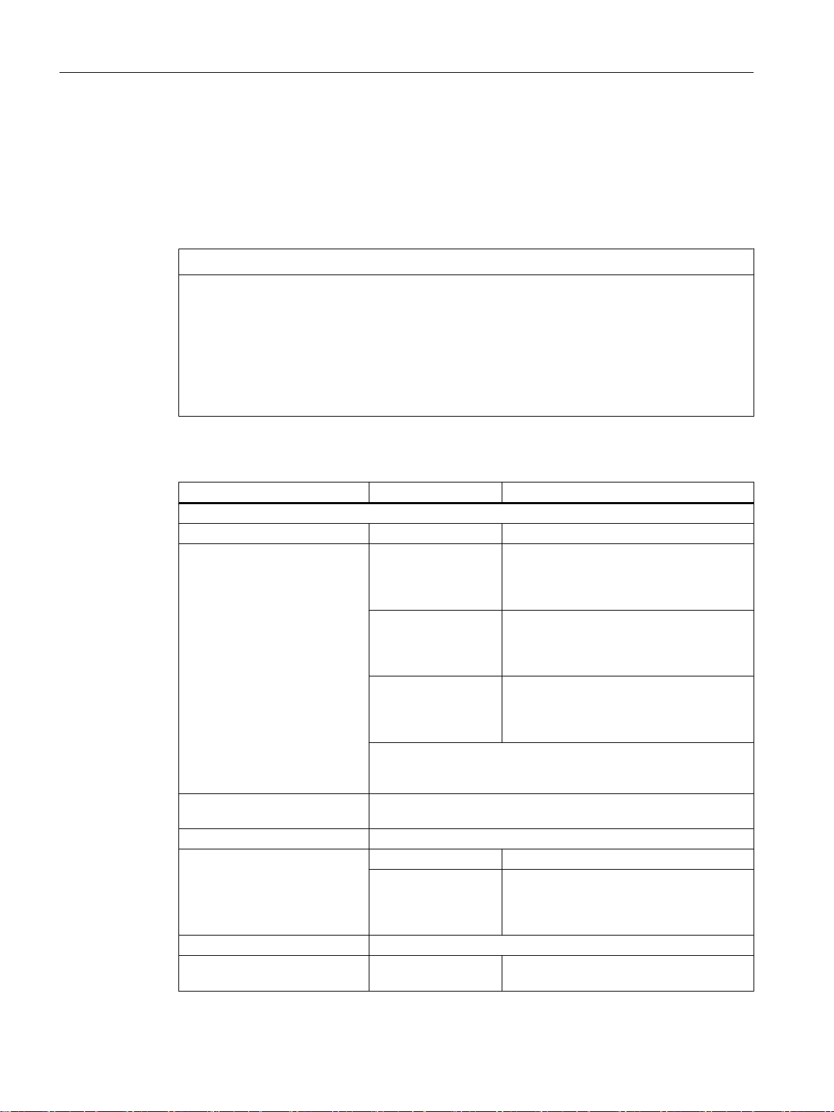
Table 1-1 Requirements of the DC power supply
Rated voltage According to EN 61131-2
Voltage range (mean value)
Voltage ripple, peak/peak
Powering up time when switched
on
Non-periodic overvoltages
Period of overvoltage
Recover time
Events per hour
Transient voltage interruptions Downtime
Recovery time
Events per hour
24 VDC
20.4 VDC to 28.8 VDC
5% (unsmoothed 6-pulse recti‐
fication)
any
≤ 35 V
≤ 500 ms
≥ 50 s
≤ 10
≤ 3 ms
≥ 10 s
≤ 10
Operator panel front: OP 012
Manual, 09/2016, A5E36371591B 11

General information and networking
1.2 Application planning
1.2.1.2 Grounding concept
Components
The SINUMERIK 840D sl system consists of a number of individual components which have
been designed so that the system complies with the appropriate EMC and safety standards.
The individual system components are:
● Numerical Control Unit (NCU)
● Machine Control Panel (MCP), Machine Pushbutton Panel (MPP)
● Keyboard
● Operator panels (operator panel front + TCU/PCU)
● Distributor box and handheld unit
● S7-300 I/O with IM 153 interface module
Grounding measures
The individual modules are attached to a metal cabinet panel. Insulating paints on the mounting
points (e.g. tension jacks) must be removed.
It is permissible to cluster the operator control components regarding connection/potential
bonding.
Example: The control panel on the swivel arm.
It is sufficient in this instance to connect the ground connections of, for example, the PCU,
TCU, and operator panel front using a cable and to route a shared grounding conductor to the
central ground connection in the control cabinet.
Additional references
EMC Design Guidelines
1.2.1.3 EMC compatibility
In addition to the protective grounding of system components, special precautions must be
taken to guarantee safe, trouble-free operation of the system. These measures include
shielded signal lines, special equipotential bonding connections, and isolation and shielding
measures.
Shielded signal cables
● For safe and fault-free operation of the system, the specified cables must be used.
● For digital signal transmission, the shield must have a conductive connection at both sides
of the housing.
Operator panel front: OP 012
12 Manual, 09/2016, A5E36371591B
Cable definition
Definition:
● Signal cables (example)
– Data cables (Ethernet, PROFIBUS, sensor cables, etc.)
– Digital I/Os
– Cables for safety functions (emergency stop, enabling)
● Power cables (example)
– Low-voltage supply lines (230 VAC, +24 VDC, etc.)
– Motor cables
Rules for routing cables
In order to achieve the greatest possible EMC compatibility for the complete system (control,
power unit, machine), the following EMC measures must be carefully observed:
● If necessary, signal and power cables may cross one another (if possible at an angle of
90°), but must never be laid close or parallel to one another.
General information and networking
1.2 Application planning
● Only use cables approved by SIEMENS for the signal lines from and to the Control Unit.
● Signal cables must not be routed close to strong external magnetic fields (e.g. motors and
transformers).
● If signal lines cannot be routed a sufficient distance away from other cables, they must be
installed in grounded cable ducts (metal).
● The operator panel fronts, MCPs, MPPs, and full keyboards must be installed in metallically
enclosed EMC-compatible housings.
Note
For further information on interference suppression measures and the connection of
shielded cables, please refer to the EMC Installation Guide.
EMC limit values in South Korea
The EMC limit values to be complied with for South Korea correspond to the limit values of the
EMC product standard for variable-speed electric drives EN 61800-3, Category C2, or limit
value class A, Group 1 according to EN 55011. By applying suitable supplementary measures,
the limit values according to Category C2 or according to limit value class A, Group 1, are
maintained. Further, additional measures may be required, for instance, using an additional
radio interference suppression filter (EMC filter).
The measures for EMC-compliant design of the system are described in detail in this manual
respectively in the Installation Guideline EMC.
Operator panel front: OP 012
Manual, 09/2016, A5E36371591B 13

General information and networking
1.2 Application planning
Please note that the final statement on compliance with the standard is given by the respective
label attached to the individual unit.
1.2.2 Ambient climatic and mechanical conditions
1.2.2.1 Transport and storage conditions
The components of the SINUMERIK 840D sl system exceed the requirements according to
EN 61800‑2 with regard to shipping and storage conditions.
The following data applies under the following conditions:
● Long-term storage in the transport and product packaging:
At weather-protected locations that have continuous contact with outside air through
openings.
● Transport in the transport packaging:
– In unventilated containers under conditions not protected from weather effects.
– In the “cold" in accordance with outside air.
– Air transport in the air-conditioned cargo hold.
Table 1-2 Ambient conditions during storage and transport
Type of condition Permissible range/class
Transport Storage
Classification EN 60721-3-2 EN 60721-3-1
Climate class 2K4 1K4
Ambient temperature
Biological environmental condi‐
tions
Chemically active environmental
conditions
Maximum permissible tempera‐
ture change
Relative humidity (without conden‐
sation)
Precipitation, rain 6 mm/min
Water other than rain 1 m/s and wet loading surfa‐
1)
-40° C ... +70° C -25° C ... +55° C
2)
2B1
3)
2C2
Direct interaction in air/air:
1B1
1C2
30 k/h
2)
3)
-40°/+30° C at 95% relative
humidity
5 to 95%
ces
2)
Not permis‐
4)
Not permissible
5)
sible
1 m/s and wet
loading surfaces
4)
Operator panel front: OP 012
14 Manual, 09/2016, A5E36371591B

Type of condition Permissible range/class
Height Max. 4,000 m above sea level
Condensation, splash water,
icing, salt spray
1)
Transport and storage of operator panel fronts and diskette drives: -20° C to +55° C.
2)
Mold growth, slime, rodents, termites and other animal vermin are not permissible.
3)
In marine- and weather-resistant transport packaging (container).
4)
For storage in the transport packaging.
5)
For storage in the product packaging.
Note
Remove the transport protective foil and packaging material before installing the components.
Shipping backup batteries
Backup batteries must only be shipped in the original packaging. No special authorization is
required to ship backup batteries. The lithium content is approximately 300 mg.
General information and networking
1.2 Application planning
Permissible Not permis‐
sible
5)
Permissible
4)
Note
The backup battery is classified as a hazardous substance, Class 9 in accordance with the
relevant air-freight transportation regulations.
Storage of backup batteries
Always store backup batteries in a cool and dry place. The batteries have a maximum shelf
life of 10 years.
Rules for handling backup batteries
WARNING
Incorrect handling of backup batteries can lead to a risk of ignition, explosion and combustion
The stipulations of DIN EN 60086-4, in particular regarding avoidance of mechanical or
electrical tampering of any kind, must be complied with.
● Do not open a battery. Replace a faulty battery only with the same type.
● Obtain replacement batteries only from Siemens.
● Always try to return low batteries to the manufacturer or deliver these to a registered
recycling company.
Operator panel front: OP 012
Manual, 09/2016, A5E36371591B 15
General information and networking
1.2 Application planning
1.2.2.2 Operating conditions
The components of the SINUMERIK 840D sl system are intended for a weatherproof, fixed
location. The documented
environmental conditions apply to the climate in the immediate vicinity of the units and to the
entry of the cooling air. They exceed the requirements according to EN 60204-1, EN 61800-2,
EN 61131-2 and IEC 62477-1.
NOTICE
Damage to components by coolants and lubricants
The SINUMERIK operator components have been designed for industrial use, particularly on
machine tools and production machines. This also takes into account the use of commercially
available coolants and lubricants. The use of aggressive compounds and additives can
damage components and result in their failure.
Contact between the operator components and coolants and lubricants should be avoided
as far as possible, as resistance to all coolants and lubricants cannot be guaranteed.
Table 1-3 Ambient conditions for operation
Environmental conditions Application areas Remarks
Climatic environmental conditions
Climate class Better than class 3K3 According to EN 60721‑3-3
Permissible ambient tempera‐
ture when installed vertically
Relative humidity (without con‐
densation)
Condensation, formation of ice Not permissible
Dripping water, spray, splash
water, jet-water according to de‐
gree of protection
Max. installation altitude Up to 4000 m (13123 ft) above sea level
Air pressure 620 hPa ... 1060 hPa According to altitude range 0 m to 4000 m
0 ... 45 °C (32 ... 113
°F), up to 2000 m
(6562 ft) above sea
level
0 ... 55 °C (32 ... 131
°F), up to 2000 m
(6562 ft) above sea
level
5 ... 55 °C (41 ... 131
°F), up to 2000 m
(6562 ft) above sea
level
Above an altitude of 2000 m (6562 ft), the max. ambient temperature
decreases by 7 °C (44.6 °F) for every 1000 m (3281 ft) increase in
altitude
5% to 95% (60% when corrosive gases and/or dusts are present)
Not permissible All components, except ...
Permissible For handheld units, front side of operator
Except PCU50.5;
front-side for OP, MCP/MPP and CNC
standard keyboards KB.
All, rear-side for OP, MCP/MPP and CNC
standard keyboards KB.
For PCU50.5
and machine control panels (MCP and
MPP), front side of the keyboards KB 310
and KB 483C
(0 ft to 13123 ft) above sea level
Operator panel front: OP 012
16 Manual, 09/2016, A5E36371591B

General information and networking
1.2 Application planning
Environmental conditions Application areas Remarks
Biological, chemical and mechanical influences, pollutants
Biological environmental conditions Class 3B1 according to EN 60 721-3-3:
Mold, mold growth, slime, rodents, termite
and other animal vermin are not permissible.
Chemically active environmental conditions Class 3C1 according to EN 60721‑3‑3
Mechanically active environmental conditions Class 3S1 according to EN 60721‑3‑3:
Conductive dust not permissible.
Classification of the mechanical
environment
Degree of contamination 2
EMC conducted / radiation Class C3 according to EN 61800-3
3M3 for components on the machine
3M1/3M2 for components in the control cab‐
inet
Note
The user must consider radio interference for the complete system. Particular attention should
be paid to cabling. Please contact your sales representative for assistance and support.
If compliance with limit value class C2 is required, please contact your local sales
representative.
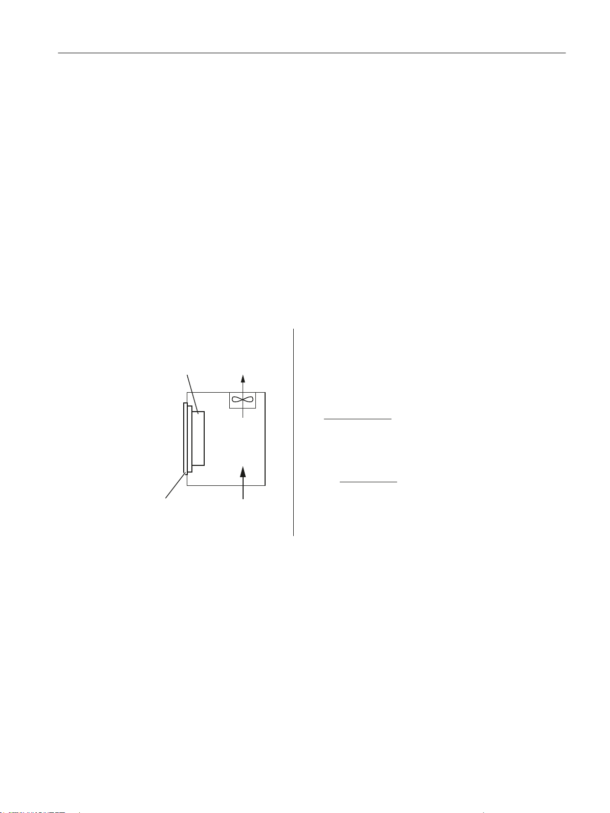
1.2.2.3 Cooling
To calculate the heat dissipation, the total power loss P
in a housing must be taken into account.
Total power loss P
Convection surface area A [m2]:
The surface areas of the front and bottom sides are not included in the convection surface
area calculation.
Note
A recommended value for the power loss of the operator control components is contained in
the "Technical data" section of the associated component (see "Power consumption").
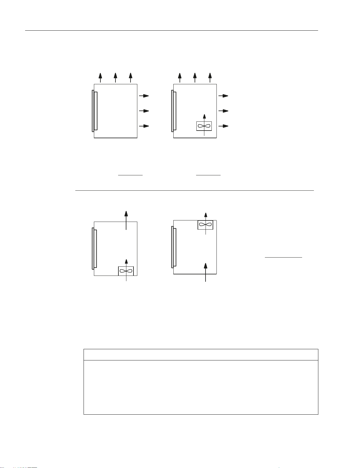
Means of heat dissipation
Heat dissipation can take place as follows:
● Heat dissipation by natural convection
● Heat dissipation by natural convection and internal air turbulence
● Heat dissipation by open-circuit cooling
● Heat dissipation by open-circuit ventilation
= PV1 + PV2 + PV3 +... [W]
Vtotal
of all heat-generating components
Vtotal
Operator panel front: OP 012
Manual, 09/2016, A5E36371591B 17
+HDWGLVVLSDWLRQ
XVLQJRSHQFLUFXLWYHQWLODWLRQ
2SHUDWRU
SDQHOIURQW
+HDWGLVVLSDWLRQ
XVLQJRSHQFLUFXLWYHQWLODWLRQ
7KHUHTXLUHGYROXPHWULF
IORZIRUGLVVLSDWLQJWKHKHDW
ORVVLVFDOFXODWHGXVLQJ
DSSUR[LPDWLRQVIURP
2SHUDWRU
SDQHOIURQW
+HDWGLVVLSDWLRQ
XVLQJQDWXUDOFRQYHQWLRQDQG
LQWHUQDOWXUEXOHQFH
+HDWGLVVLSDWLRQ
XVLQJQDWXUDOFRQYHFWLRQ
7KHUHTXLUHGIUHHFRQYHFWLRQVXUIDFH$>P@RIWKH
URRPWREHFRQYHUWHGVWHHORUDOXPLQXPVKHHWLQJPPWKLFNQHVVLVFDOFXODWHGEDVHGRQ
DWHPSHUDWXUHGLIIHUHQFH77 ෙ7ุ.DSSUR[LPDWHGIURP
YROXPHWULFIORZRIWKHIDQ
PK
2SHUDWRU
SDQHOIURQW
2SHUDWRU
SDQHOIURQW
39
JHV
>:@
39
JHV
>:@39
JHV
>:@
7
7
˂7>.@
9>PK@
7
7
˂7>.@
$>P@
7
7
˂7>.@
$>P@
7
7
General information and networking
1.2 Application planning
Figure 1-1 Means of heat dissipation
Fan design
● The fan must be positioned to produce an optimum heat dissipation. A clearance of 10 mm
must be maintained in front of the fan.
● The inlet and outlet slots must remain free for the open-circuit ventilation.
● Air filters must be provided to maintain the permitted environmental conditions.
NOTICE
Damage to the operating components caused by temperatures that are too high or too low
Contaminated air filters impair the desired heat dissipation. For handling the air filters, pay
attention to:
● Proper handling
● Regular replacement
● Correct disposal
18 Manual, 09/2016, A5E36371591B
Operator panel front: OP 012
Guidelines
&DOFXODWLRQRIWKHSRZHUORVV
LQFOXGLQJLQWHUQDOSRZHUVXSSO\XQLW
([DPSOHIRUKHDWGLVVLSDWLRQZLWKRSHQFLUFXLWYHQWLODWLRQ
3&8ZLWK23
PD[:
,QWHUQDOWHPSHUDWXUH 7 r&
([WHUQDOWHPSHUDWXUH 7 r&
9 >PK@
39
JHV
>:@
39
JHV
:
˂7>.@
3&8:
23:
7
7
ය˂7 .
3&8
23
General information and networking
1.2 Application planning
If the convection area A [m2] does not suffice for the "heat dissipation using natural convection",
then use:
● "Heat dissipation using natural convection and internal turbulence" for hot spots and heat
concentrations in housings subject to space constraints. The total power loss P
Ltot
for
thermally critical applications can be determined as follows:
– Current measurement for a 24 V supply voltage
– Power loss P
● Heat dissipation using open-circuit ventilation
Calculation of the volumetric flow
The power loss (thermal) dissipated by the components in an operator unit is to be dissipated
using open-circuit ventilation. The volumetric flow V required for this should be calculated at
a difference in temperature of T2 - T1 = ΔT ≥ 10K.
[W] = U (24 V) * |measured value in ampères|
Ltot
Figure 1-2 Calculating heat dissipation for PCU 50.5 with OP 019
Operator panel front: OP 012
Manual, 09/2016, A5E36371591B 19

General information and networking
1.2 Application planning
1.2.3 Standards and approvals
Approvals
CE approval
Figure 1-3 CE marking
The operator panels and the safety-relevant accessories satisfy the requirements and
protection objectives of the following EC directives. The operator panels and the safetyrelevant accessories comply with the harmonized European standards (EN), promulgated in
the Official Journals of the European Community:
● 2004/108/EC "Electromagnetic Compatibility" (EMC directive)
● Directive 2006/42/EC of the European Parliament and Council of May 17, 2006, on
machinery, and Directive 95/16/EC (amendment)
SIBE Switzerland Certification Service
For the HT 2 and HT 8 units.
Figure 1-4 Symbol of the certifying body
HT 2
The HT 2 operator panel and the safety-relevant accessories (is identified in the "Accessories"
section for the respective devices) satisfy Category 3, PL d according to EN ISO 13849-1:2008.
The safety function Enabling device for special mode control and the emergency stop button
satisfy the following requirements:
● Category 3, PL d according to EN ISO 13849-1:2008
● Requirements of EN 60204-1:2006, when complying with the safety instructions in the
relevant chapters of this documentation
HT 8
The HT 8 operator panel and the safety-relevant accessories (is identified in the "Accessories"
section for the respective devices) satisfy Category 3, PL d according to EN ISO 13849-1:2008.
The emergency stop button meets the following requirements:
● Category 3, PL d according to EN ISO 13849-1:2008
● Requirements of EN 60204-1:2006, when complying with the safety instructions in the
relevant chapters of this documentation
Operator panel front: OP 012
20 Manual, 09/2016, A5E36371591B

Risk assessment
General information and networking
1.2 Application planning
The safety function Enabling device for special mode control satisfies the following
requirements:
● Category 4, PL e according to EN ISO 13849-1:2008
● Requirements of EN 60204-1:2006, when complying with the safety instructions in the
relevant chapters of this documentation
Address:
NSBIV AG, SIBE Switzerland, Brünigstrasse 18, CH-6005 Lucerne
Accreditation SCESp 0046 / Notified Body 1247
Number of the prototype test certificate: No. 1416
The following standards must be used to perform the risk assessment:
● EN ISO 12100-1:2003 and EN ISO 12100-2:2003, General Design Guidelines for Machines
● EN ISO 14121-1:2007, Risk Assessment for Machinery
● EN ISO 13849-1:2008, Safety-related Parts of Machines
These considerations result in a category (B, 1, 2, 3, 4) and a performance level (PL a to e) in
accordance with EN ISO 13849-1:2008 that ultimately dictate how the safety-related parts of
the system to be monitored must be constructed.
The connection examples with different monitoring units in "Handheld units", Section: "HT 2",
Section: "Connections" → "Connection examples for acknowledgment button and Emergency
Stop button" can also be used for other operator panels and demonstrate how Category 3, PL
d according to EN ISO 13849-1:2008 can be attained with the safety-related parts of the
operator panels. Note that the overall concept of the installation must be designed with this in
mind.
1.2.4 Recycling and disposal
Products should be disposed of corresponding to the relevant national regulations.
The products described in this manual can be mostly recycled due to the fact that they contain
very few damaging substances. To recycle and dispose of your old device in an
environmentally friendly way, please contact an appropriate disposal company.
Operator panel front: OP 012
Manual, 09/2016, A5E36371591B 21

General information and networking
1.3 Connecting
1.3 Connecting
1.3.1 Pin assignment of the interfaces
The pins of the component interfaces are assigned as specified in the tables below. Any
deviations are indicated at the relevant point.
Signal type:
I Input
O Output
B Bidirectional (inputs/outputs)
V Power supply
- Ground (reference potential) or N.C. (not connected)
Power supply interface
Serial interface COM1
Connector type: Terminal block, 3-pin plug connector
Max. cable length: 10 m
Table 1-4 Assignment of the power supply interface
Pin Name Type Meaning
1 P24 (+) - 24 VDC potential (20.4 to 28.8 VDC)
2 M24 (-)
3 SHIELD (PE) Shield potential
VI
Ground 24 V
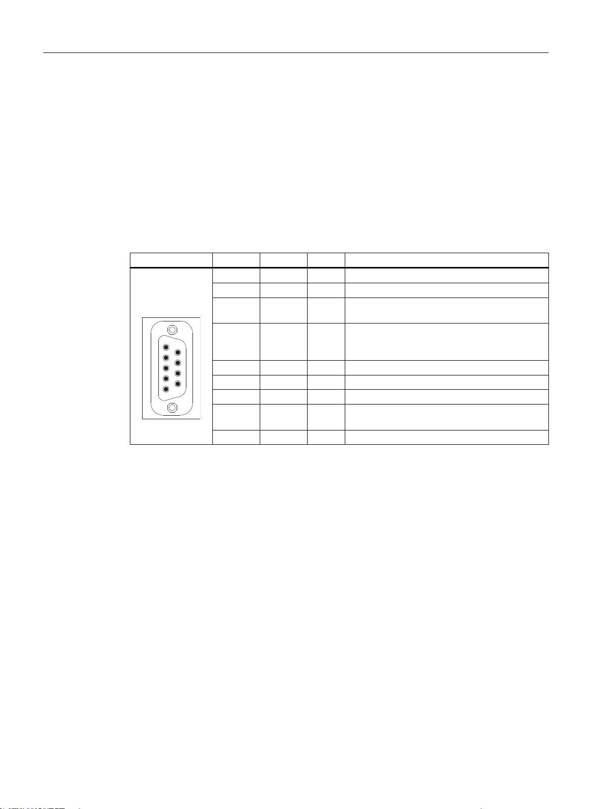
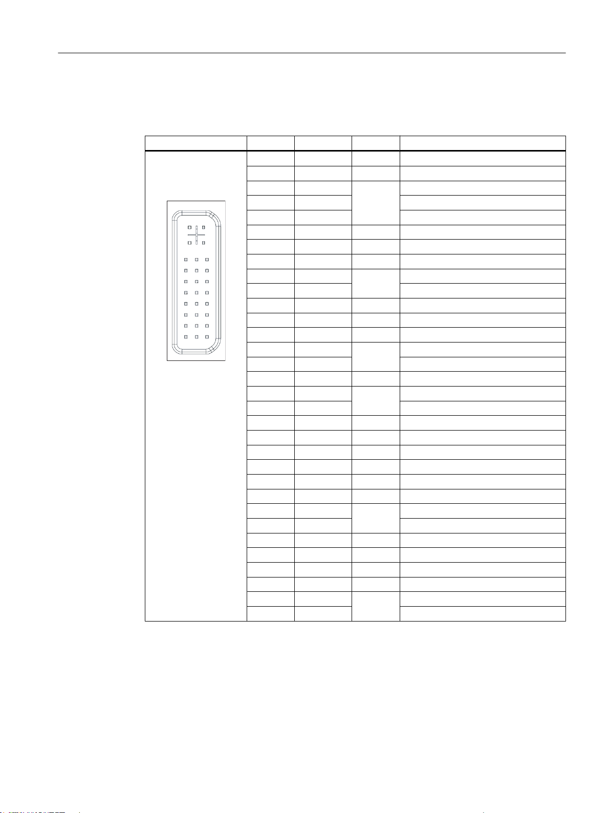
9-pin sub-D connector
Table 1-5 Assignment of the serial interface COM1 (V.24/RS232)
Connector Pin Name Type Remark
1 DCD (M5)
2 RxD (D2) Serial receive data
3 TxD (D1)
4 DTR (S1) Data terminal ready
5 GND (E2) - Ground (reference potential)
6 DSR (M1) I Data Set Ready
7 RTS (S2) O Request To Send
8 CTS (M2)
9 RI (M3) Incoming call
Receive signal level (carrier)
I
Serial transmit data
O
Clear To Send
I
22 Manual, 09/2016, A5E36371591B
Operator panel front: OP 012

USB interfaces
General information and networking
1.3 Connecting
The USB interfaces are implemented as sockets and comply with the generally valid standard.
The version information (1.1, 2.0 etc.), the maximum velocity (low speed, full speed, etc.) and
the socket type (A or B) are documented in the individual sections for the associated devices.
In principle, USB interfaces have the following characteristics:
● Integrated power supply up to 500 mA for each socket.
● Maximum cable length 3 m (Length including the supply cable to the hub and the connected
terminal device; only 1 hub at maximum is permitted. It should be noted that some
keyboards already have a hub.)
NOTICE
Cables that are too long can cause the screen to freeze
Observe the following restrictions for the USB front interface for connecting operator
panels to the keyboard, mouse or USB FlashDrive:
● Maximum cable length: 1.8 m
● Extension cables are not permissible
● Hot-plugging-capable devices are connected during operation and are identified
automatically.
Note
Correct identification is only guaranteed for USB I/Os that comply to 100% with the USB
specification.
Table 1-6 Assignment of the USB interface
Type A socket Type B socket Pin Name Type Remark
1 P5V_fused V + 5 V (fused)
2 Data3 Data+ Data +
4 GND V Ground (reference potential)
Data -
B
USB sticks
If you want to connect a USB stick to the USB interface, preferably use the tested SIMATIC
USB stick 16 GB for this purpose (Article No.: 6ES7648-0DC60-0AA0). Alternatively, you can
use a USB stick with any memory size. It must, however, meet the following minimum
requirements:
● File system: FAT16 or FAT32
● Partitioning: only in PC partition format (MBR)
Operator panel front: OP 012
Manual, 09/2016, A5E36371591B 23
General information and networking
1.3 Connecting
USB sticks that deviate from these requirements have not been tested can may not be
recognized by the NCU.
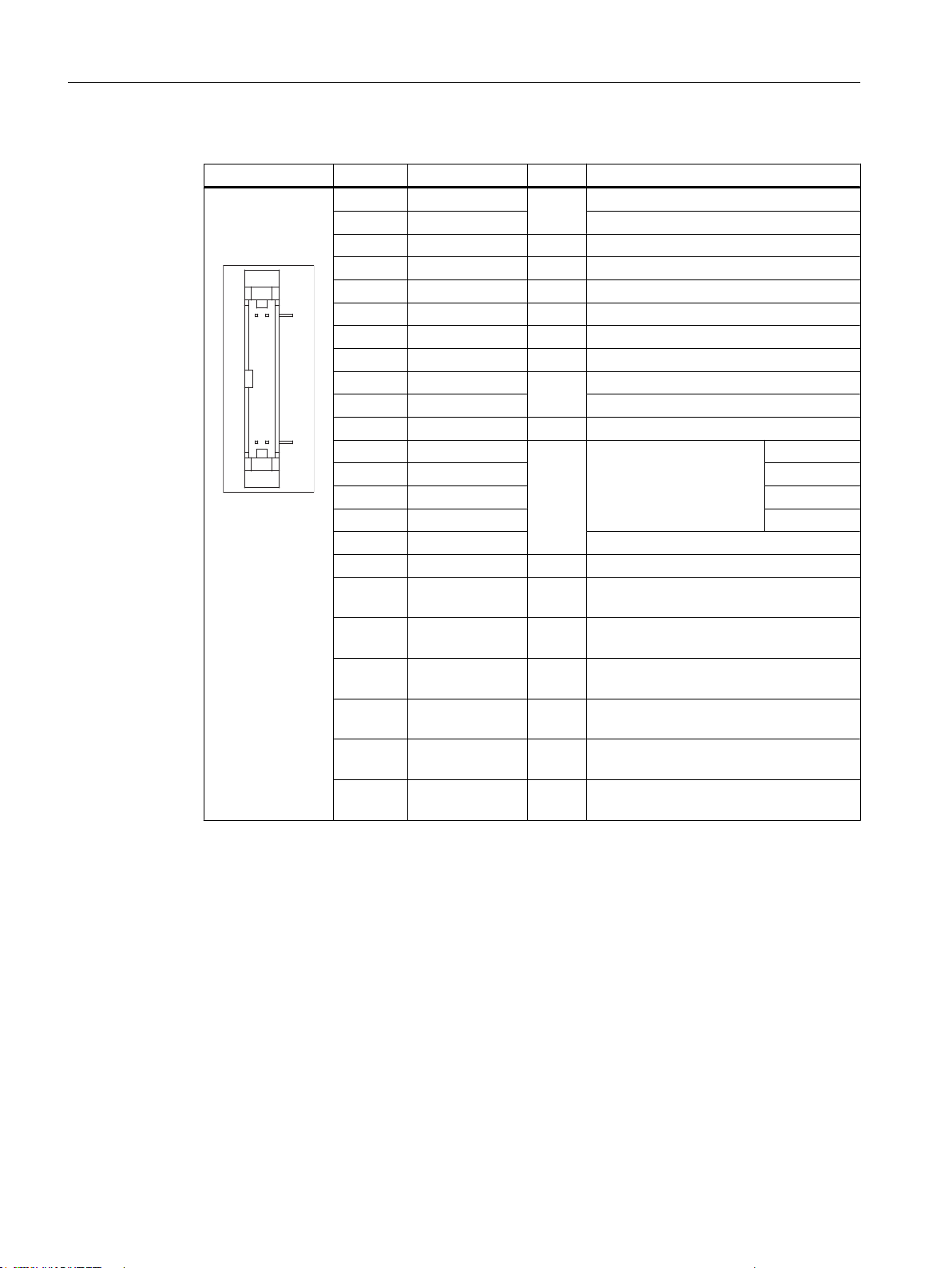
PROFIBUS DP / MPI interface
Connector type: 9-pin sub-D socket
Max. data transmission rate: 12 Mbit/s
Max. cable length: 100 m
Table 1-7 Assignment of the PROFIBUS DP / MPI interface
Connector Pin Name Type Remark
1,2 N.C. - Not connected
3 LTG_B B Signal line B of MPI module
4 RTS_AS I Control signal for receive data current. Signal 1
active if directly connected control is sending.
5 M5EXT V Return line (GND) of 5 V supply. Current load
from a load of 90 mA max. connected between
P5EXT and M5EXT.
6 P5EXT V 5 V supply (current load see M5EXT)
7 N.C. - Not connected
8 LTG_A B Signal line A of MPI module
9 RTS_PG O RTS signal of MPI module; signal is "1", when
PG is sending
Shield - On connector housing
PROFIBUS DP interface
Connector type: 9-pin sub-D socket
Max. data transmission rate: 12 Mbit/s
Max. cable length: 100 m
Operator panel front: OP 012
24 Manual, 09/2016, A5E36371591B
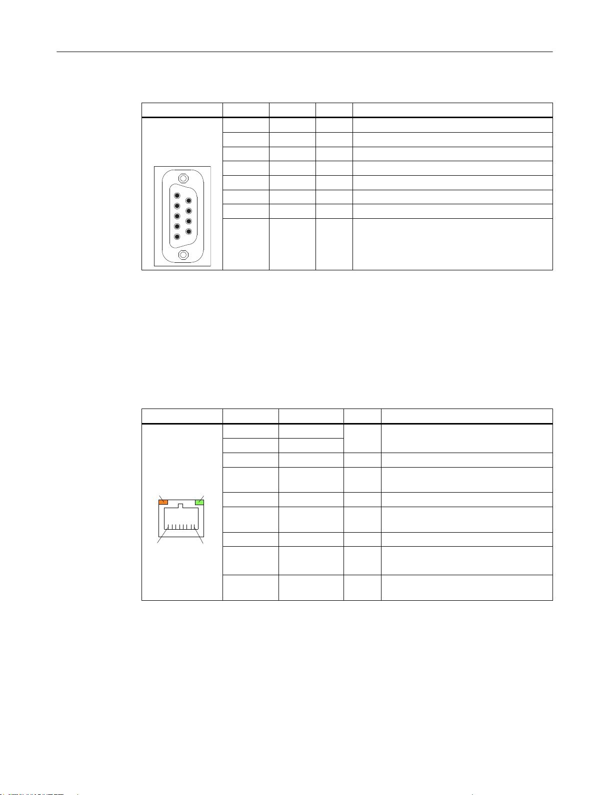
Table 1-8 Assignment of the PROFIBUS DP interface
/('/('
Connector Pin Name Type Remark
Ethernet RJ45 interface
Connector type: Standard RJ45 socket
Max. data transmission rate: 10/100/1000 Mbit/s
Max. cable length: 100 m
General information and networking
1.3 Connecting
1,2 N.C. - Not connected
3 RS_DP B RS-485 differential signal
4 RTS_DP O Request To Send
5 M5EXT V 5 V external ground
6 P5EXT V 5 V external potential
7 N.C. - Not connected
8 XRS_DP B RS-485 differential signal
9 N.C. - Not connected
Table 1-9 Assignment of the Ethernet RJ45 interface 10/100 Mbit/s
Connector Pin Name Type Remark
1 TxD+
2 TxD3 RxD+ I Receive data
4/5 GND - (terminated internally with 75 Ω; not re‐
6 RD- I Receive data
7/8 GND - (terminated internally with 75 Ω; not re‐
Shield - - On connector housing
- Green LED
(right)
- Orange LED
(left)
O Transmit data
quired for data transmission)
quired for data transmission)
- Lights up: 10 or 100 Mbit/s
Off: No or faulty connection
- Illuminated: Data exchange
Off: No data exchange
Operator panel front: OP 012
Manual, 09/2016, A5E36371591B 25
/('/('
General information and networking
1.3 Connecting
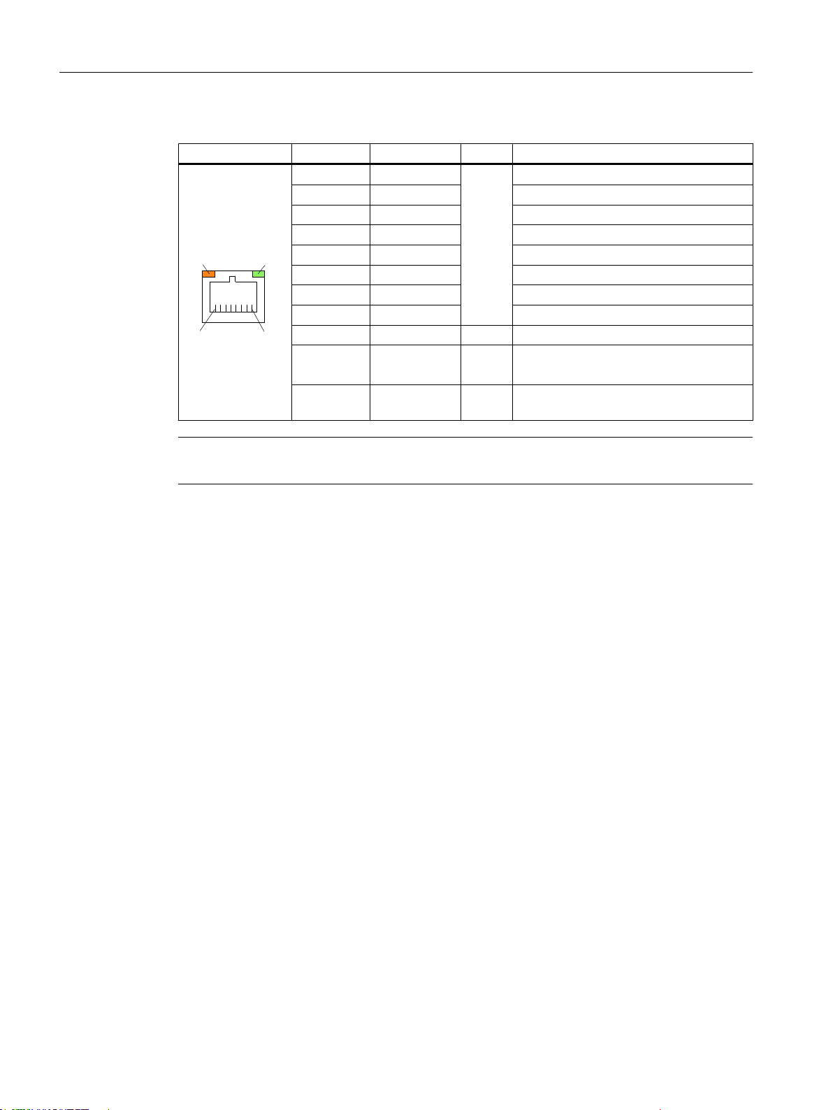
Table 1-10 Assignment of the Ethernet RJ45 interface 1000 Mbit/s
Connector Pin Name Type Remark
Note
1 DA+ B Bidirectional pair A+
2 DA- Bidirectional pair A3 DB+ Bidirectional pair B+
4 DC+ Bidirectional pair C+
5 DC- Bidirectional pair C6 DB- Bidirectional pair B7 DD+ Bidirectional pair D+
8 DD- Bidirectional pair D-
Shield - - On connector housing
- Green LED
(right)
- Orange LED
(left)
- Illuminated orange: 1000 Mbit/s
Off: No or faulty connection
- Illuminated: Data exchange
Off: No data exchange
Connection only on LAN, not on telecommunication networks!
26 Manual, 09/2016, A5E36371591B
Operator panel front: OP 012
DVI-I interface
&
&
&
&&
Table 1-11 Assignment of DVI-I interface
Connector Pin Name Type Remark
S GND - Ground
S1 GND - Ground
C1 R
C2 G Green
C3 B Blue
C4 HSYNC O Horizontal synchronizing pulse
C5 GND - Ground
CSA GND - Ground
1 TX2N
2 TX2P TDMS data 2+
3 GND - Ground
4 N.C. - Not connected
5 N.C. - Not connected
6 DDC CLK
7 DDC CLK DDC data
8 VSYNC O Vertical synchronizing pulse
9 TX1N
10 TX1P TDMS data 1+
11 GND - Ground
12 N.C. - Not connected
13 N.C. - Not connected
14 + 5 V VO + 5 V
15 GND VO Ground
16 MONDET I Hot plug detect
17 TX0N
18 TXoP TDMS data 0+
19 GND - Ground
20 N.C. - Not connected
21 N.C. - Not connected
22 GND - Ground
23 TXCP
24 TXCN TDMS clock -
General information and networking
1.3 Connecting
Red
O
TDMS data 2-
O
DDC clock
B
TDMS data 1-
O
TDMS data 0-
O
TDMS clock +
O
I/O USB interface
Operator panel front: OP 012
Manual, 09/2016, A5E36371591B 27
All signals required for connecting operator panel fronts, with the exception of the display
interface, are assigned to this interface.
Associated interface cable: K1
Connector type: 2 x 13-pin socket connector
General information and networking
1.3 Connecting
Table 1-12 Allocation of the I/O USB interface
Connector Pin Name Type Meaning
1 GND
2 P12C +power supply for backlight inverter
3 BL_ON O Backlight On
4 P5V_fused VO +5 V VCC (fused in PCU/TCU)
5 GND VO Ground
6 P3V3_fused VO +3.3 V VCC (fused in PCU/TCU)
7 - 10 N.C. - Not connected
11 P5V_fused VO +5 V VCC (fused in PCU/TCU)
12 USB_D1M
13 USB_D1P USB data+ Channel 1
14 GND VO Ground
15 LCD_SEL0
16 LCD_SEL1 2
17 LCD_SEL2 3
18 LCD_SEL3 4
19 RESET_N Reset signal (low active)
20 reserved - Reserved
21 HD_LED O HD LED, anode with 1 kΩ in series on the
22 DP_LED O MPI/DP LED, anode with 1 KΩ in series
23 Ethernet_LED O Ethernet LED, anode with 1 kΩ in series
24 TEMP_ERR O LED temperature sensor; anode with 1
25 RUN_R *) O Watchdog error LED, anode with 1 kΩ in
26 RUN_G O Watchdog OK LED, anode with 1 kΩ in
Ground
VO
USB data- Channel 1
B
Display type select signal
I
motherboard
on the motherboard
on the motherboard
kΩ in series on the board
series on the motherboard
series on the motherboard
1
LVDS display interface channel 1
28 Manual, 09/2016, A5E36371591B
Used to connect operator panel fronts with TFT displays with 640 x 480 pixels (VGA), 800 x
600 pixels (SVGA) or 1024 x 768 pixels (XGA).
Associated interface cable: K2, max. length: 0.5 m
Connector type: 2 x 10-pin socket connector
Operator panel front: OP 012
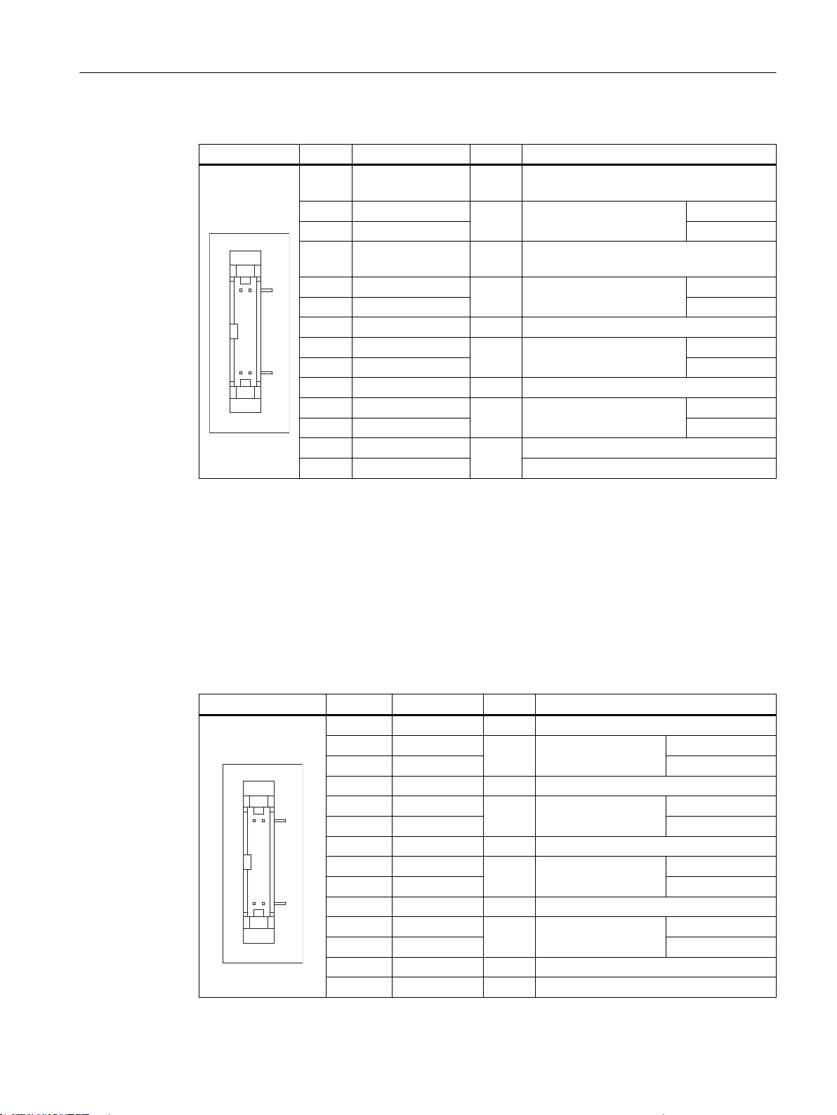
Table 1-13 Allocation of the LVDS display interface
Connector Pin Name Type Meaning
1/2 P5V_D_fused VO +5 V display supply voltage (fused in PCU/
3 RXIN04 RXIN0+ Bit 0 (+)
5/6 P3V3_D_fused VO +3.3 V display supply voltage (fused in PCU/
7 RXIN18 RXIN1+ Bit 1 (+)
9/10 GND - System ground (reference potential)
11 RXIN212 RXIN2+ Bit 2 (+)
13/14 GND - System ground (reference potential)
15 RXCLKIN-
16 RXCLKIN+ (+)
17/18 GND
19/20 N.C. Not connected
I LVDS input signal
I LVDS input signal
I LVDS input signal
O LVDS cycle clock signal
-
General information and networking
1.3 Connecting
TCU)
Bit 0 (-)
TCU)
Bit 1 (-)
Bit 2 (-)
(-)
System ground (reference potential)
LVDS display interface channel 2
Used for expanding the LVDS display interface channel 1 to control TFT displays with 1280 x
1024 pixels (SXGA).
Associated interface cable: K3
Connector type: 2 x 10-pin socket connector
Table 1-14 Allocation of the LVDS display interface
Connector Pin Name Type Meaning
1/2 GND - System ground (reference potential)
3 RXIN104 RXIN10+ Bit 0 (+)
5/6 GND - System ground (reference potential)
7 RXIN18 RXIN1+ Bit 1 (+)
9/10 GND - System ground (reference potential)
11 RXIN212 RXIN2+ Bit 2 (+)
13/14 GND V Ground
15 RXCLKIN16 RXCLKIN+ (+)
17 GND V Ground
18-20 P12VF VO +12 V fused
LVDS input signal Bit 0 (-)
I
LVDS input signal Bit 1 (-)
I
LVDS input signal Bit 2 (-)
I
LVDS cycle clock sig‐
O
nal
(-)
Operator panel front: OP 012
Manual, 09/2016, A5E36371591B 29

General information and networking
1.3 Connecting
Rotary switch: Feed override X30
Connector designation: X30
Connector type: 2 x 5-pin plug connector, according to EN 60603-13 with coding
Max. cable length: 0.6 m
Table 1-15 Assignment of X30 connector (on delivery)
Pin Name Type Meaning
1 N.C. - Not connected
2 N.C. - Not connected
3 M V Ground
4 N.C. - Not connected
5 P5 V 5 V supply
6 OV_VS16
7 OV_VS8 Override rotary switch value 8
8 OV_VS4 Override rotary switch value 4
9 OV_VS2 Override rotary switch value 2
10 OV_VS1 Override rotary switch value 1
Override rotary switch value 16
I
Rotary switch: Spindle override X31
Connector designation: X31
Connector type: 2 x 5-pin plug connector, according to EN 60603-13 with coding
Max. cable length: 0.6 m
Table 1-16 Assignment of X31 connector (on delivery)
Pin Name Type Meaning
1 N.C. - Not connected
2 N.C. - Not connected
3 M V Ground
4 N.C. - Not connected
5 P5 V 5 V supply
6 OV_SP16
7 OV_SP8 Override rotary switch value 8
8 OV_SP4 Override rotary switch value 4
9 OV_SP2 Override rotary switch value 2
10 OV_SP1 Override rotary switch value 1
Override rotary switch value 16
I
Operator panel front: OP 012
30 Manual, 09/2016, A5E36371591B
 Loading...