

Siemens Sinumerik 840D Series, Simodrive 611 digital, SINUMERIK 840DiE, SINUMERIK 840D, SINUMERIK 840DE Function Manual
...Page 1

Description of Functions 10/2003 Edition
sinumerik
& simodrive
HLA Module
SINUMERIK 840D
SIMODRIVE 611 digital
Page 2

Page 3

General 1
Configuration 2
Installation and Start-Up 3
Firmware Drive Functions 4
SINUMERIK 840D
SIMODRIVE 611 digital
HLA module
Description of Functions
Hardware Drive Functions 5
Hydraulics Diagnostics 6
Peripherals/Accessories 7
Service 8
Valid for
Control Software Version
SINUMERIK 840D 5, 6
SINUMERIK 840DE (export version) 5, 6
SINUMERIK 840Di 2
SINUMERIK 840DiE (export version) 2
10.03 Edition
Hydraulics A
Abbreviations B
Definition of Terms C
References D
EC Declaration of
Conformity E
Index F
Page 4

O
Printed in Germany
3ls
SINUMERIK Documentation
Revision history
Brief details of this edition and previous editions are listed below.
The status of each edition is indicated by the code in the “Remarks” column.
Status code in the “Remarks” column:
A New documentation. . . . . .
B Unmodified reprint with new order number . . . . .
C Revised version with new edition status. . . . . .
If the technical subject matter shown on the page has changed compared to the
previous edition status, this is indicated by the changed edition status in the header
of the respective page.
Edition Order no. Remarks
02/99 6SN1197-0AB60-0BP0 A
08/99 6SN1197-0AB60-0BP1 C
04/00 6SN1197-0AB60-0BP2 C
10/03 6SN1197-0AB60-0BP3 C
This manual is supplied as part of the CD-ROM documentation (DOCONCD)
Edition Order no. Remarks
03/04 6FC5 298-7CA00-0BG3 C
Trademarks
SIMATICr, SIMATIC HMIr, SIMATIC NETr, SIROTECr, SINUMERIKr, SIMODRIVEr and
MOTION-CONNECTr are registered trademarks of Siemens AG. Other names in this publication might be
trademarks whose use by a third party for his own purposes may violate the rights of the registered holder.
More information is available on the Internet at:
http://www.siemens.com/motioncontrol
This document was created with Interleaf V 7
The reproduction, transmission or use of this document or its
contents is not permitted without express written authority. Offenders
will be liable for damages. All rights, including rights created by patent
grant or registration or a utility model or design, are reserved.
Siemens AG, 1999-2004. All rights reserved
Other functions not described in this documentation might be
executable in the control. This does not, however, represent an
obligation to supply such functions with a new control or when
servicing.
We have checked that the contents of this document correspond to
the hardware and software described. Nevertheless, differences
might exist and therefore we cannot guarantee that they are
completely identical. The information given in this publication is
reviewed at regular intervals and any corrections that might be
necessary are made in subsequent editions. We welcome all
recommendations and suggestions.
Subject to change without prior notice
rder no. 6SN1197-0AB60-0BP3
Siemens Aktiengesellschaft.
Page 5

Preface
Notes for the Reader
Structure of the
documentation
Target group
The documentation for SIMODRIVE 611/SINUMERIK 840D is organized on the
following levels:
S General Documentation
S Manufacturer/Service Documentation
S Electronic Documentation
The description of functions of the HLA module is part of the
SIMODRIVE/SINUMERIK documentation.
For further information about the publications listed in the documentation overview and other available SIMODRIVE/SINUMERIK publications, please contact
your local Siemens sales office.
This Description of Functions does not purport to cover all details or variations
in equipment, nor to provide for every possible contingency to be met in connection with installation, operation or maintenance.
The contents of this document shall neither become part of nor modify any prior
or existing agreement, commitment or relationship. The Sales Contract contains
the entire obligations of Siemens. The warranty contained in the contract between the parties is the sole warranty of Siemens. Any statements contained
herein do not create new warranties or modify the existing warranty.
This documentation is intended for use by machine manufacturers and
servicing personnel who use the “HLA modules”.
Objective
This Description of Functions provides the information required to configure and
start up the hydraulic drive module.
S Chapter 2 describes the procedures for configuring the electric and hydraulic
components.
S Chapter 3 shows how the hydraulic drive is started up with the support of a
menu-driven user interface.
S The firmware and the HLA module hardware functionality are explained in
Chapters 4 and 5.
S Chapter 6 explains how to check and interpret status displays and alarms
(hydraulic diagnostics).
S Chapter 7 describes the accessories required, e.g. measuring systems and
cables.
S Appendix A contains general information and an explanation of the hydraulic
system functionality.
Siemens AG, 2003. All rights reserved
SINUMERIK 840D/SIMODRIVE 611 digital, HLA Module (FBHLA) - 10.03 Edition
v
Page 6

Note
Preface
Hydraulics In this document, information about specific hydraulic functions
refers to functions provided by Bosch Rexroth AG.
10.03
How to use this
manual
Definition of
qualified persons
The following guide information is provided to help you reference information in
this Description of Functions:
S General table of contents
S Header (as orientation aid):
- The top line of the header is the main section number
- The second line of the header is the subsection number
S Appendix with
- abbreviations, terms and references
- Glossary (index)
For the purpose of this manual and product labels, a “qualified person” is one
who is familiar with the installation, mounting, start-up and operation of the
equipment and the hazards involved.
S Training or instruction/permit for connecting electric circuits and devices in
accordance with safety technology standards.
S Training and instruction in maintenance and use of adequate safety equip-
ment according to safety regulations.
S Trained in rendering first aid.
Software version
The SW versions specified in this documentation refer to the SINUMERIK 840D
control system and the HLA module.
The Description of Functions applies only to the software versions specified.
When a new software version is released, the Description of Functions for that
version must be ordered.
vi
SINUMERIK 840D/SIMODRIVE 611 digital, HLA Module (FBHLA) - 10.03 Edition
Siemens AG, 2003. All rights reserved
Page 7

10.03
Preface
Explanation of
symbols
The following danger and warning concept is used in this document:
Danger
!
!
!
This symbol appears whenever death, severe physical injury or substantial material damage
will occur if appropriate precautions are not taken.
Warning
This symbol appears whenever death, severe physical injury or substantial material damage
may occur if appropriate precautions are not taken.
Caution
This symbol appears whenever minor physical injury or material damage may occur if
appropriate precautions are not taken.
Caution
This warning (without warning triangle) indicates that material damage may occur if
appropriate precautions are not taken.
Notice
This warning indicates that an undesirable result or an undesirable state may occur if the
information is ignored.
Note
In the context of this document, it is advisable to take note of the warning information.
Siemens AG, 2003. All rights reserved
SINUMERIK 840D/SIMODRIVE 611 digital, HLA Module (FBHLA) - 10.03 Edition
vii
Page 8

Hotline
Preface
10.03
The hotline phone numbers appear in Chapter 8.
Should you have any questions about the documentation (suggestions, correc-
tions), please fax them to:
Fax: +49 (9131) 98-2176
Fax form: See the reply form at the end of the brochure
viii
SINUMERIK 840D/SIMODRIVE 611 digital, HLA Module (FBHLA) - 10.03 Edition
Siemens AG, 2003. All rights reserved
Page 9

10.03
Preface
Danger and warning notices
Danger
!
Commissioning should not start until you have ensured that the machine
in which the components described here are to be installed complies with
Directive 98/37/EC.
Only appropriately qualified personnel may commission/start-up this
equipment.
The personnel must take into account the information provided in the technical
customer documentation for the product, and be familiar with and observe the
specified danger and warning notices.
When electrical devices are operated, the electrical circuits automatically
conduct a dangerous voltage.
Dangerous mechanical movements may occur in the system during operation.
All work on the electrical system must be carried out when the system has
been disconnected from the power supply.
Warning
!
!
Proper transportation, expert storage, installation and mounting, as well as
careful operation and maintenance are essential for this device to operate
correctly and reliably.
In addition to the danger and warning information provided in the technical
customer documentation, applicable national, local, and system-specific
regulations must be taken into account.
The information given in catalogs and quotations applies additionally to special
versions of machines and equipment.
Caution
When attaching the connecting cables, you must ensure that:
S They must not be damaged
S They must not be stressed
S They cannot come into contact with rotating parts
Caution
As part of routine tests, the devices undergo a voltage test in accordance with
EN 50178. During voltage testing of electrical equipment on industrial
machines in accordance with EN 60204-1, Section 19.4, all SIMODRIVE
device connections must be disconnected/removed. This is necessary in order
to avoid damaging the SIMODRIVE devices.
Siemens AG, 2003. All rights reserved
SINUMERIK 840D/SIMODRIVE 611 digital, HLA Module (FBHLA) - 10.03 Edition
ix
Page 10

10.03
Preface
ESD notices
Electrostatic Sensitive Devices
Components which can be destroyed by electrostatic discharge are individual
components, integrated circuits or boards which, when handled, tested or
transported, could be destroyed by electrostatic fields or electrostatic
discharge. These components are designated as ESDS (ElectroStatic
Discharge Sensitive Devices).
Handling of modules containing devices sensitive to electrostatic discharge:
S When handling components which can be destroyed by electrostatic
discharge, it must be ensured that personnel, the workstation and
packaging are well grounded,.
S As a general principle, electronic modules should only be touched if this is
absolutely unavoidable (owing to repair work, etc.).
S Touch components only if
- you are constantly grounded by an antistatic armband,
- you are wearing ESD boots or ESD boots with grounding strips in
conjunction with ESD flooring.
S Modules may be placed only on electrically conductive surfaces (table with
ESD top, conductive ESD foam plastic, ESD packing bags, ESD transport
containers).
S Keep modules away from visual display units, monitors or TV sets
(minimum distance from screen > 10 cm).
S Do not bring ESD-sensitive modules into contact with chargeable and
highly-insulating materials, such as plastic, insulating table tops or clothing
made of synthetic materials.
S Measurements on modules are allowed only if
- the measuring instrument is properly grounded (e.g. equipment
grounding conductor), or
- before measuring, with an isolated measuring instrument, the
measuring head is briefly discharged (e.g. touching a bare metal control
housing).
S Closed-loop control modules, option modules and memory submodules
may only be held by the front plate or on the board edges.
J
x
SINUMERIK 840D/SIMODRIVE 611 digital, HLA Module (FBHLA) - 10.03 Edition
Siemens AG, 2003. All rights reserved
Page 11

Table of Contents
1 General 1-15. . . . . . . . . . . . . . . . . . . . . . . . . . . . . . . . . . . . . . . . . . . . . . . . . . . . . . . . . . .
1.1 Typical applications 1-15. . . . . . . . . . . . . . . . . . . . . . . . . . . . . . . . . . . . . . . .
1.2 Comparison of electric and hydraulic drive systems 1-16. . . . . . . . . . . . .
1.3 Structure of an electro-hydraulically-controlled drive axis 1-18. . . . . . . .
1.3.1 Machine guideway 1-18. . . . . . . . . . . . . . . . . . . . . . . . . . . . . . . . . . . . . . . . .
1.3.2 Cylinder 1-19. . . . . . . . . . . . . . . . . . . . . . . . . . . . . . . . . . . . . . . . . . . . . . . . . .
1.3.3 Servo solenoid valve 1-19. . . . . . . . . . . . . . . . . . . . . . . . . . . . . . . . . . . . . . .
1.3.4 Valve amplifier 1-19. . . . . . . . . . . . . . . . . . . . . . . . . . . . . . . . . . . . . . . . . . . . .
1.3.5 Shutoff valve 1-19. . . . . . . . . . . . . . . . . . . . . . . . . . . . . . . . . . . . . . . . . . . . . .
1.3.6 Position measuring system 1-19. . . . . . . . . . . . . . . . . . . . . . . . . . . . . . . . . .
1.3.7 SINUMERIK 840D/SIMODRIVE 611 digital 1-20. . . . . . . . . . . . . . . . . . . .
1.3.8 Hydraulic power unit 1-20. . . . . . . . . . . . . . . . . . . . . . . . . . . . . . . . . . . . . . .
2 Configuration 2-21. . . . . . . . . . . . . . . . . . . . . . . . . . . . . . . . . . . . . . . . . . . . . . . . . . . . .
2.1 Configuring steps 2-21. . . . . . . . . . . . . . . . . . . . . . . . . . . . . . . . . . . . . . . . . .
2.1.1 Procedure for configuring electrical components 2-21. . . . . . . . . . . . . . .
2.1.2 Procedure for configuring hydraulic components 2-22. . . . . . . . . . . . . . .
2.2 Integration in SINUMERIK 840D/SIMODRIVE 611 digital 2-24. . . . . . . .
2.2.1 System overview 2-24. . . . . . . . . . . . . . . . . . . . . . . . . . . . . . . . . . . . . . . . . .
2.2.2 Required FW packages 2-29. . . . . . . . . . . . . . . . . . . . . . . . . . . . . . . . . . . . .
2.2.3 Hardware requirements 2-29. . . . . . . . . . . . . . . . . . . . . . . . . . . . . . . . . . . . .
2.3 Configuring the hydraulic drive 2-30. . . . . . . . . . . . . . . . . . . . . . . . . . . . . . .
2.3.1 Cylinder selection 2-30. . . . . . . . . . . . . . . . . . . . . . . . . . . . . . . . . . . . . . . . . .
2.3.2 Selection of servo solenoid valves 2-32. . . . . . . . . . . . . . . . . . . . . . . . . . .
2.3.3 Selection of shutoff valves 2-39. . . . . . . . . . . . . . . . . . . . . . . . . . . . . . . . . .
2.3.4 Natural frequency of the hydraulic drive 2-42. . . . . . . . . . . . . . . . . . . . . . .
2.3.5 Hydraulic power unit 2-43. . . . . . . . . . . . . . . . . . . . . . . . . . . . . . . . . . . . . . .
2.4 Connection 2-45. . . . . . . . . . . . . . . . . . . . . . . . . . . . . . . . . . . . . . . . . . . . . . .
2.4.1 Internal power supply 2-45. . . . . . . . . . . . . . . . . . . . . . . . . . . . . . . . . . . . . . .
2.4.2 External power supply 2-45. . . . . . . . . . . . . . . . . . . . . . . . . . . . . . . . . . . . . .
2.4.3 Grounding concept/Electromagnetic compatibility (EMC) 2-48. . . . . . . .
3 Installation and Start-Up 3-49. . . . . . . . . . . . . . . . . . . . . . . . . . . . . . . . . . . . . . . . . . .
3.1 Overview of start-up process 3-49. . . . . . . . . . . . . . . . . . . . . . . . . . . . . . . .
3.2 Drive configuration 3-51. . . . . . . . . . . . . . . . . . . . . . . . . . . . . . . . . . . . . . . . .
3.3 Modify drive machine data 3-52. . . . . . . . . . . . . . . . . . . . . . . . . . . . . . . . . .
3.4 Valve selection 3-53. . . . . . . . . . . . . . . . . . . . . . . . . . . . . . . . . . . . . . . . . . . .
3.5 Cylinder selection 3-56. . . . . . . . . . . . . . . . . . . . . . . . . . . . . . . . . . . . . . . . . .
3.6 Mounting/supply data 3-57. . . . . . . . . . . . . . . . . . . . . . . . . . . . . . . . . . . . . . .
3.7 Measuring system data 3-58. . . . . . . . . . . . . . . . . . . . . . . . . . . . . . . . . . . . .
3.8 Modifying data 3-59. . . . . . . . . . . . . . . . . . . . . . . . . . . . . . . . . . . . . . . . . . . .
3.9 Fine adjustment and optimization 3-62. . . . . . . . . . . . . . . . . . . . . . . . . . . .
Siemens AG, 2003. All rights reserved
SINUMERIK 840D/SIMODRIVE 611 digital, HLA Module (FBHLA) - 10.03 Edition
xi
Page 12

3.9.1 Control direction, travel direction 3-62. . . . . . . . . . . . . . . . . . . . . . . . . . . . .
Contents
3.9.2 Offset adjustment 3-64. . . . . . . . . . . . . . . . . . . . . . . . . . . . . . . . . . . . . . . . . .
3.9.3 Velocity adjustment 3-65. . . . . . . . . . . . . . . . . . . . . . . . . . . . . . . . . . . . . . . .
3.9.4 Referencing data for HLA 3-67. . . . . . . . . . . . . . . . . . . . . . . . . . . . . . . . . . .
3.9.5 Controller optimization 3-68. . . . . . . . . . . . . . . . . . . . . . . . . . . . . . . . . . . . . .
3.9.6 Controller adaptation 3-73. . . . . . . . . . . . . . . . . . . . . . . . . . . . . . . . . . . . . . .
3.9.7 Hydraulic/electrical interpolation 3-74. . . . . . . . . . . . . . . . . . . . . . . . . . . . .
3.10 File functions 3-75. . . . . . . . . . . . . . . . . . . . . . . . . . . . . . . . . . . . . . . . . . . . . .
3.11 Start-up functions 3-76. . . . . . . . . . . . . . . . . . . . . . . . . . . . . . . . . . . . . . . . . .
3.11.1 Measurement function 3-77. . . . . . . . . . . . . . . . . . . . . . . . . . . . . . . . . . . . . .
3.11.2 Function generator 3-84. . . . . . . . . . . . . . . . . . . . . . . . . . . . . . . . . . . . . . . . .
3.11.3 Circularity test 3-88. . . . . . . . . . . . . . . . . . . . . . . . . . . . . . . . . . . . . . . . . . . . .
3.11.4 Servo trace 3-88. . . . . . . . . . . . . . . . . . . . . . . . . . . . . . . . . . . . . . . . . . . . . . .
3.11.5 DAC parameter settings 3-89. . . . . . . . . . . . . . . . . . . . . . . . . . . . . . . . . . . .
3.12 User views 3-90. . . . . . . . . . . . . . . . . . . . . . . . . . . . . . . . . . . . . . . . . . . . . . . .
3.13 Display options 3-91. . . . . . . . . . . . . . . . . . . . . . . . . . . . . . . . . . . . . . . . . . . .
3.14 Configuring an OEM valve list 3-92. . . . . . . . . . . . . . . . . . . . . . . . . . . . . . .
10.03
3.15 System variables 3-94. . . . . . . . . . . . . . . . . . . . . . . . . . . . . . . . . . . . . . . . . .
4 Firmware Drive Functions 4-95. . . . . . . . . . . . . . . . . . . . . . . . . . . . . . . . . . . . . . . . . .
4.1 Block diagram of closed-loop control 4-95. . . . . . . . . . . . . . . . . . . . . . . . .
4.2 Functions 4-97. . . . . . . . . . . . . . . . . . . . . . . . . . . . . . . . . . . . . . . . . . . . . . . . .
4.2.1 Overview of functions 4-97. . . . . . . . . . . . . . . . . . . . . . . . . . . . . . . . . . . . . .
4.2.2 Parameter set changeover 4-98. . . . . . . . . . . . . . . . . . . . . . . . . . . . . . . . . .
4.3 Closed-loop velocity control 4-99. . . . . . . . . . . . . . . . . . . . . . . . . . . . . . . . .
4.3.1 Velocity adaptation/feedforward control 4-99. . . . . . . . . . . . . . . . . . . . . . .
4.3.2 Velocity controller 4-106. . . . . . . . . . . . . . . . . . . . . . . . . . . . . . . . . . . . . . . . . .
4.3.3 Dynamic stiffness control (DSC) 4-114. . . . . . . . . . . . . . . . . . . . . . . . . . . . .
4.4 Closed-loop force control 4-115. . . . . . . . . . . . . . . . . . . . . . . . . . . . . . . . . . .
4.4.1 Force limitation 4-117. . . . . . . . . . . . . . . . . . . . . . . . . . . . . . . . . . . . . . . . . . . .
4.4.2 Static friction injection 4-118. . . . . . . . . . . . . . . . . . . . . . . . . . . . . . . . . . . . . .
4.4.3 Force controller 4-119. . . . . . . . . . . . . . . . . . . . . . . . . . . . . . . . . . . . . . . . . . . .
4.5 Manipulated voltage output 4-124. . . . . . . . . . . . . . . . . . . . . . . . . . . . . . . . . .
4.5.1 Characteristic compensation 4-124. . . . . . . . . . . . . . . . . . . . . . . . . . . . . . . .
4.5.2 Control output filter 4-130. . . . . . . . . . . . . . . . . . . . . . . . . . . . . . . . . . . . . . . . .
4.5.3 Manipulated voltage limitation 4-132. . . . . . . . . . . . . . . . . . . . . . . . . . . . . . .
4.6 Supply unit data 4-133. . . . . . . . . . . . . . . . . . . . . . . . . . . . . . . . . . . . . . . . . . .
4.7 Valve 4-134. . . . . . . . . . . . . . . . . . . . . . . . . . . . . . . . . . . . . . . . . . . . . . . . . . . . .
4.8 Cylinder drive 4-136. . . . . . . . . . . . . . . . . . . . . . . . . . . . . . . . . . . . . . . . . . . . .
4.9 Drive data 4-137. . . . . . . . . . . . . . . . . . . . . . . . . . . . . . . . . . . . . . . . . . . . . . . .
4.10 Position measuring system 4-140. . . . . . . . . . . . . . . . . . . . . . . . . . . . . . . . . .
4.11 Pressure sensing system 4-145. . . . . . . . . . . . . . . . . . . . . . . . . . . . . . . . . . .
4.12 Terminals 4-146. . . . . . . . . . . . . . . . . . . . . . . . . . . . . . . . . . . . . . . . . . . . . . . . .
4.13 Monitoring functions 4-152. . . . . . . . . . . . . . . . . . . . . . . . . . . . . . . . . . . . . . . .
xii
SINUMERIK 840D/SIMODRIVE 611 digital, HLA Module (FBHLA) - 10.03 Edition
Siemens AG, 2003. All rights reserved
Page 13

10.03
Contents
4.13.1 Alarms 4-152. . . . . . . . . . . . . . . . . . . . . . . . . . . . . . . . . . . . . . . . . . . . . . . . . . .
4.13.2 Variable signaling functions 4-154. . . . . . . . . . . . . . . . . . . . . . . . . . . . . . . . .
4.14 Service functions 4-159. . . . . . . . . . . . . . . . . . . . . . . . . . . . . . . . . . . . . . . . . .
4.14.1 Min/max display 4-159. . . . . . . . . . . . . . . . . . . . . . . . . . . . . . . . . . . . . . . . . . .
4.14.2 Monitor 4-160. . . . . . . . . . . . . . . . . . . . . . . . . . . . . . . . . . . . . . . . . . . . . . . . . . .
4.14.3 Diagnostic machine data 4-161. . . . . . . . . . . . . . . . . . . . . . . . . . . . . . . . . . . .
4.15 Parameters table 4-165. . . . . . . . . . . . . . . . . . . . . . . . . . . . . . . . . . . . . . . . . .
5 Hardware Drive Functions 5-175. . . . . . . . . . . . . . . . . . . . . . . . . . . . . . . . . . . . . . . . . .
5.1 Interface overview 5-175. . . . . . . . . . . . . . . . . . . . . . . . . . . . . . . . . . . . . . . . .
5.1.1 Measuring system 5-178. . . . . . . . . . . . . . . . . . . . . . . . . . . . . . . . . . . . . . . . .
5.1.2 Pressure sensor system 5-179. . . . . . . . . . . . . . . . . . . . . . . . . . . . . . . . . . . .
5.1.3 Servo solenoid valve 5-180. . . . . . . . . . . . . . . . . . . . . . . . . . . . . . . . . . . . . . .
5.1.4 Terminals 5-181. . . . . . . . . . . . . . . . . . . . . . . . . . . . . . . . . . . . . . . . . . . . . . . . .
5.1.5 Test sockets (diagnostics) 5-182. . . . . . . . . . . . . . . . . . . . . . . . . . . . . . . . . . .
5.1.6 Bus interfaces 5-183. . . . . . . . . . . . . . . . . . . . . . . . . . . . . . . . . . . . . . . . . . . . .
5.2 System environment 5-184. . . . . . . . . . . . . . . . . . . . . . . . . . . . . . . . . . . . . . .
5.3 Notes 5-185. . . . . . . . . . . . . . . . . . . . . . . . . . . . . . . . . . . . . . . . . . . . . . . . . . . .
5.3.1 Climatic and mechanical environmental conditions in operation 5-185. . .
5.3.2 Transport and storage conditions 5-186. . . . . . . . . . . . . . . . . . . . . . . . . . . .
5.3.3 Stress caused by contaminants 5-187. . . . . . . . . . . . . . . . . . . . . . . . . . . . . .
6 Hydraulics Diagnostics 6-189. . . . . . . . . . . . . . . . . . . . . . . . . . . . . . . . . . . . . . . . . . . .
7 Peripherals/Accessories 7-219. . . . . . . . . . . . . . . . . . . . . . . . . . . . . . . . . . . . . . . . . . .
7.1 Measuring systems 7-219. . . . . . . . . . . . . . . . . . . . . . . . . . . . . . . . . . . . . . . .
7.1.1 Encoders, linear scales 7-219. . . . . . . . . . . . . . . . . . . . . . . . . . . . . . . . . . . . .
7.1.2 Connection diagrams 7-222. . . . . . . . . . . . . . . . . . . . . . . . . . . . . . . . . . . . . . .
7.2 BERO (X432) 7-226. . . . . . . . . . . . . . . . . . . . . . . . . . . . . . . . . . . . . . . . . . . . .
7.3 Pressure sensor 7-227. . . . . . . . . . . . . . . . . . . . . . . . . . . . . . . . . . . . . . . . . . .
7.3.1 Sensor equipment 7-227. . . . . . . . . . . . . . . . . . . . . . . . . . . . . . . . . . . . . . . . .
7.3.2 Connection diagrams 7-231. . . . . . . . . . . . . . . . . . . . . . . . . . . . . . . . . . . . . . .
7.4 Connection diagrams for servo solenoid valves 7-232. . . . . . . . . . . . . . . .
8 Service 8-237. . . . . . . . . . . . . . . . . . . . . . . . . . . . . . . . . . . . . . . . . . . . . . . . . . . . . . . . . . .
8.1 Areas of responsibility at Siemens/Bosch Rexroth 8-237. . . . . . . . . . . . . .
8.2 Hotline and contacts 8-238. . . . . . . . . . . . . . . . . . . . . . . . . . . . . . . . . . . . . . .
A Hydraulics A-239. . . . . . . . . . . . . . . . . . . . . . . . . . . . . . . . . . . . . . . . . . . . . . . . . . . . . . . .
A.1 Servo solenoid valves A-239. . . . . . . . . . . . . . . . . . . . . . . . . . . . . . . . . . . . . .
A.1.1 General A-239. . . . . . . . . . . . . . . . . . . . . . . . . . . . . . . . . . . . . . . . . . . . . . . . . .
A.1.2 Directly-controlled servo solenoid valves, sizes 6 and 10 A-247. . . . . . . .
A.1.3 Pilot-controlled servo solenoid valves, sizes 10 and 16 A-249. . . . . . . . . .
A.1.4 HR servo solenoid valves A-252. . . . . . . . . . . . . . . . . . . . . . . . . . . . . . . . . . .
A.2 Cylinder A-254. . . . . . . . . . . . . . . . . . . . . . . . . . . . . . . . . . . . . . . . . . . . . . . . . .
Siemens AG, 2003. All rights reserved
SINUMERIK 840D/SIMODRIVE 611 digital, HLA Module (FBHLA) - 10.03 Edition
xiii
Page 14

B Abbreviations B-257. . . . . . . . . . . . . . . . . . . . . . . . . . . . . . . . . . . . . . . . . . . . . . . . . . . . .
Contents
C Definition of Terms C-259. . . . . . . . . . . . . . . . . . . . . . . . . . . . . . . . . . . . . . . . . . . . . . . .
D References D-261. . . . . . . . . . . . . . . . . . . . . . . . . . . . . . . . . . . . . . . . . . . . . . . . . . . . . . . .
D.1 Electrical applications D-261. . . . . . . . . . . . . . . . . . . . . . . . . . . . . . . . . . . . . .
D.2 Hydraulic applications D-274. . . . . . . . . . . . . . . . . . . . . . . . . . . . . . . . . . . . . .
E EC Declaration of Conformity E-275. . . . . . . . . . . . . . . . . . . . . . . . . . . . . . . . . . . . . .
F Index Index-279. . . . . . . . . . . . . . . . . . . . . . . . . . . . . . . . . . . . . . . . . . . . . . . . . . . . . . . . . . . . .
10.03
xiv
SINUMERIK 840D/SIMODRIVE 611 digital, HLA Module (FBHLA) - 10.03 Edition
Siemens AG, 2003. All rights reserved
Page 15

General
1.1 Typical applications
1
Applications
Objective
Interfaces
The NCU 573.2 of the SINUMERIK 840D is capable of handling axis configurations of a maximum of 31 axes on up to 10 different channels. This functional
sophistication makes the SINUMERIK 840D an increasingly popular system for
the automation of rotary indexing machines. These machines are often highly
compact in design and frequently equipped with hydraulic axes (cylinders and
servo solenoid valves). The hydraulics (HLA) module provides a means of controlling hydraulic axes directly from the SINUMERIK 840D system via the digital
drive bus.
The HLA module is a closed-loop control plug-in unit of the modular
SIMODRIVE 611 converter system mounted in a 50 mm carrier module
(universal empty housing).
The gating and closed-loop control electronics for operating controlled hydraulic
drives are integrated on the HLA module.
From the point of view of the manufacturer of modern servo solenoid valves, an
innovative step in the field of hydraulic drive systems has been taken by treating
electric and hydraulic drives as equal partners and integrating them into a standard NC.
To place equal emphasis on the functional importance of both hydraulic and
electric drives and make them available as a combined system within an interpolating axis grouping.
S Firmware
The communications interface is compatible with the SIMODRIVE 611D
SRM(FDD)/ARM(MSD) for supported services. Code and data management
is analogous to the SIMODRIVE 611D SRM(FDD)/ARM(MSD). The hydraulics software is stored as a separate program code in the control system.
S Hardware
The mode of integration into the SIMODRIVE 611 system is compatible with
the SIMODRIVE 611 digital SRM(FDD)/ARM(MSD). This basically involves
the following interfaces:
- Drive bus
- Device bus
- Power supply system
Siemens AG, 2003. All rights reserved
SINUMERIK 840D/SIMODRIVE 611 digital, HLA Module (FBHLA) - 10.03 Edition
1-15
Page 16

1.2 Comparison of electric and hydraulic drive systems
1 General
1.2 Comparison of electric and hydraulic drive systems
Table 1- 1 Comparison of electric and hydraulic drive systems
10.03
Criterion Electric direct drive Electric drive with
Power density /
mounting
space requirements
Mass inertia of
moving parts
Operational
reliability,
service life
S Low weight and
S reduced spatial re-
quirements of the
electric part on the
machine table.
Electric part on machine
table has low mass.
Service life depends in
principle only on linear
guides.
S Servomotor and leads-
S Problematic with lim-
Servomotor and leadscrew have high mass moment of inertia.
S Shock-sensitive.
S Service life limited by
leadscrew
crew large and heavy.
ited mounting space.
leadscrew.
S Sudden failure
possible.
Servicing Simple replacement Expensive replacement
and repair of leadscrew by
specialists.
Energy storage Peak requirement must
be installed as no storage
is possible.
Maximum
forces
Load stiffness Very good;
maximum velocity
Maximum
travel path
Collision
protection
Peak thrust per unit area
approx. 40 to 80 kN/m
Servo gain can be set to
betw. 10-100 times
higher than on the other
two drives.
Up to 500 m/min v
Unlimited
Mechanically difficult Mechanically possible Mechanically possible
Peak requirement must be
installed as no storage is
possible.
Restriction with larger
2
forces.
S Elasticity under large
forces.
S Elasticity of leadscrew
is largely compensated as a control
function.
@ ω
max=hs
h
=thread lead
s
ω
=max. motor speed
max
v 6 m v 3 m
max
/2π
Hydraulic drive
S Cylinder and servo sole-
noid valve are light-weight
and compact.
S Transfer of E motor to
hydraulic power unit.
Piston and piston rod have
very low mass
S Protected against overload
by pressure limitation.
S Sturdy, insensitive to
shocks.
S Cylinder seals and valve
control edges have long
service life.
S Warning of wear.
S Simple error diagnosis
S Simple replacement and
repair of valves and cylinders.
S Compensation of energy
requirement peaks by hydraulic accumulator.
S Rapid traverse in differen-
tial circuit.
S Reduction of installed ca-
pacity.
Practically unlimited
(cylinderφ, p
=700 bar)
max
S Oil compressibility is com-
pensated as a control
function (I component).
S Good zero overlap quality
of valve ensures very high
rigidity under load.
30...300 m/min
(depending on which cylinder
seal kit is used)
1-16
SINUMERIK 840D/SIMODRIVE 611 digital, HLA Module (FBHLA) - 10.03 Edition
Siemens AG, 2003. All rights reserved
Page 17

1 General
02.99
10.03
1.2 Comparison of electric and hydraulic drive systems
Table 1-1 Comparison of electric and hydraulic drive systems
Criterion Hydraulic driveElectric drive with
Noise Noise produced by
Acceleration
Electric direct drive
leadscrew
Noise produced by servo-
linear guides
motor and leadscrew
max. 45 g max. 1 g max. 2 g
characteristics
Drive cooling Absolutely essential Required only at high
speeds
Sensitivity to
High Low Low
ferromagnetic
swarf
Table 1-2 Analogy of characteristic data
Electric Hydraulic
Spindle speed Velocity Velocity
Current flowrate
DC link voltage System pressure
Power Flow rate @ Valve pressure differential
Transistor/power section Valve
Motor Drive cylinder
S Flow through valve may
produce noise.
S Pump noise on
hydraulic power unit.
Required in some cases, in
power unit only
Siemens AG, 2003. All rights reserved
SINUMERIK 840D/SIMODRIVE 611 digital, HLA Module (FBHLA) - 10.03 Edition
1-17
Page 18
1.3 Structure of an electro-hydraulically-controlled drive axis
1 General
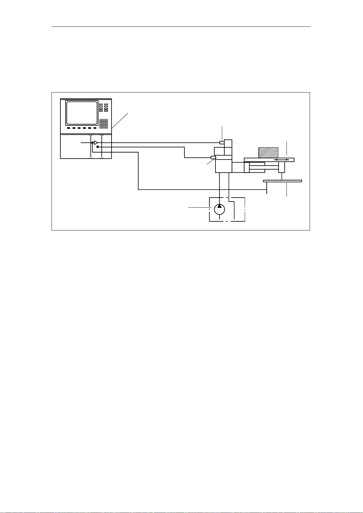
1.3 Structure of an electro-hydraulically-controlled drive
axis
SINUMERIK 840D,
SIMODRIVE 611 digital
with HLA module
Shutoff valve
Servo solenoid value with
valve amplifier (OBE)
Machine guideway
02.99
10.03
Hydraulic power unit
Fig. 1-1 Construction of an electro-hydraulically controlled drive axis
1.3.1 Machine guideway
Guide mechanism
Friction
Hydrodynamic and hydrostatic slideways or roller slideways allow machine
slides and tables to move in straight lines with minimum friction and maximum
precision.
A degree of friction can be very useful for damping oscillations.
However, excessive friction, especially pronounced transitions from static to
sliding friction, have a negative effect on the control result and impair the control
loop stability.
Position
measuring
system
1-18
SINUMERIK 840D/SIMODRIVE 611 digital, HLA Module (FBHLA) - 10.03 Edition
Siemens AG, 2003. All rights reserved
Page 19

1 General
02.99
10.03
1.3.2 Cylinder
1.3 Structure of an electro-hydraulically-controlled drive axis
Construction
Quality criteria
The cylinder represents the simplest form of linear motor and can be integrated
easily into the machine guide. The cylinder normally has a piston rod at one
end.
The following are critical quality criteria:
S The surface quality of barrel and piston rod and
S The seals and guides (low-friction, servo quality...).
1.3.3 Servo solenoid valve
Task
Function
This is the final control element in the closed control loop and forms the electrohydraulic converter.
The valve steplessly converts electrical signals into a hydraulic flow.
Its quality is defined by static and dynamic parameters, such as
S Zero overlap
S Hysteresis
S Limit frequency, etc.
1.3.4 Valve amplifier
This circuit contains the power electronics for the solenoid in the servo solenoid
valve which adjusts the valve spool position.
The position controller in the valve amplifier (on-board electronics - OBE) controls the position of the valve spool proportionally to the output value
(U=0..."10 V).
1.3.5 Shutoff valve
Shut-off valves are used to add safety functions to a valve control with servo
solenoid valve. Shut-off valves can prevent uncontrolled motion of the cylinder.
1.3.6 Position measuring system
Task
The position measuring system supplies the actual value for the position of the
moving machine element.
Siemens AG, 2003. All rights reserved
SINUMERIK 840D/SIMODRIVE 611 digital, HLA Module (FBHLA) - 10.03 Edition
1-19
Page 20

1.3 Structure of an electro-hydraulically-controlled drive axis
1 General
02.99
10.03
Function
The speed is acquired by continuous differentiation of the distance over time.
Various systems are available depending on the level of accuracy required.
The highest accuracy requirements are fulfilled by digital systems (glass scale
with photoelectric evaluation circuit) mounted directly on the machine.
The most widely used digital incremental systems require a reference point approach at the beginning of a machining operation.
1.3.7 SINUMERIK 840D/SIMODRIVE 611 digital
SINUMERIK controls and SIMODRIVE drive systems are specially designed for
machine tools, manipulators and special-purpose machines.
The numerical control processes the machine program and converts it into control commands. It also monitors command execution continuously.
The control structures for the electrohydraulic control loop and the interfaces to
S the shutoff valve,
S the servo solenoid valve,
S the position measuring system and
S the central arithmetic logic unit
are all provided by the HLA module.
The HLA module is an integral component of the SINUMERIK 840D and
SIMODRIVE 611 digital systems.
A range of different NCU modules with graded scope of functions is provided to
allow the SINUMERIK 840D system to be tailored to the varying functional requirements of machines. The control can therefore be optimally adapted to individual machines and machining applications and is suitable for equipping standardized machine series.
1.3.8 Hydraulic power unit
This unit supplies hydraulic energy.
It is installed at a distance from the drive axis. Accumulators are employed to
compensate for strongly fluctuating hydraulic energy requirements and to minimize the installed power.
J
1-20
SINUMERIK 840D/SIMODRIVE 611 digital, HLA Module (FBHLA) - 10.03 Edition
Siemens AG, 2003. All rights reserved
Page 21
Configuration
2.1 Configuring steps
2.1.1 Procedure for configuring electrical components
The procedure for configuring an HLA module is divided into steps in such a
way that the user is guided through the full range of relevant settings, from the
required force, to the hydraulics components, and finally the HLA and its encoder evaluation circuitry. This initial configuring phase may be followed by a
second in some cases, in which the corresponding circuit recommendations
and EMC measures are taken into account.
The functions of SIMODRIVE components are described with keywords in this
Planning Guide. Limit values for functions may be specified in some cases.
For further details (e.g. characteristics), please refer to the Installation and
Start-Up Guides for SIMODRIVE 611 digital and SINUMERIK 840 digital.
Further configuring instructions and detailed ordering information can be found
in Catalogs NC 60 and NC Z.
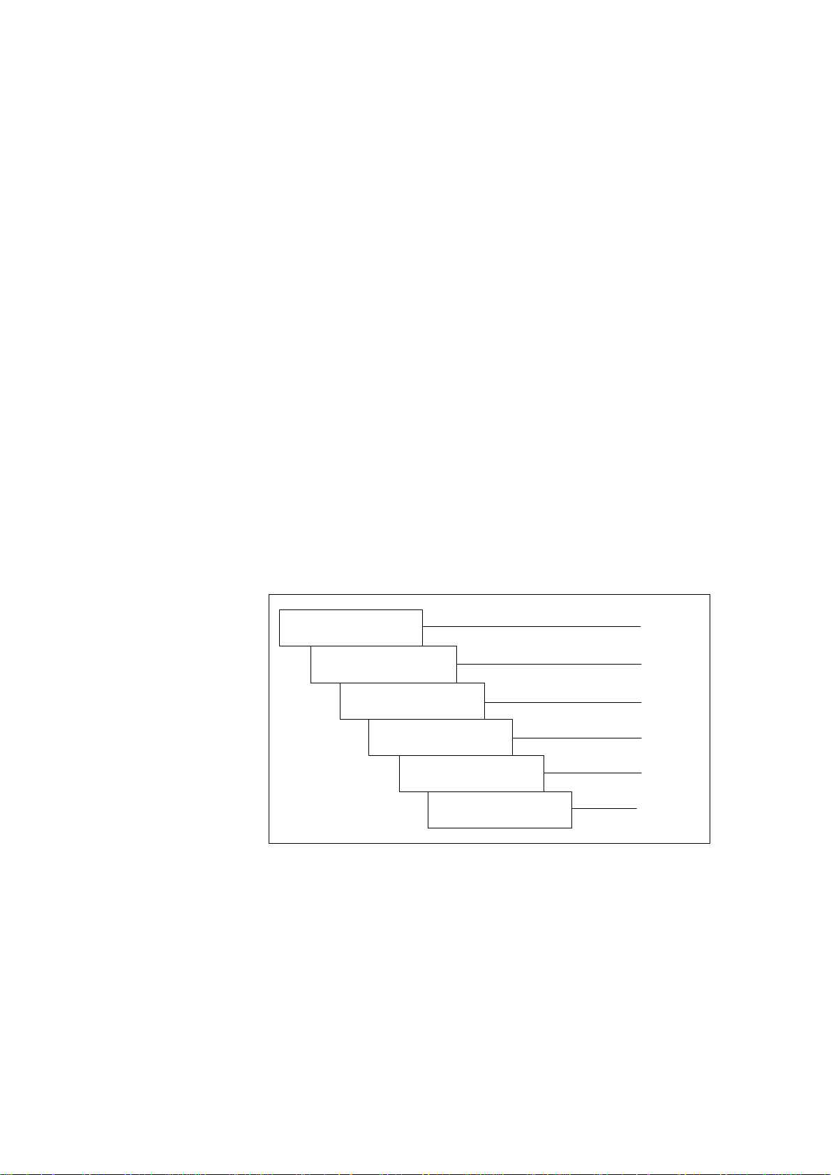
Phase 1
Selection of hydraulic
components
Dimensioning of incoming
mains supply
Dimensioning of
power modules
Dimensioning of external
power supply
Dimensioning of closedloop control components
and publication from Bosch Rexroth AG
and publication 6SN1197-0AA00
and publication 6SN1197-0AA00
2
Section 2.3
Section 2.2
Section 2.2
Section 2.4
Chapter 4
Dimensioning of position
sensor (measuring system)
Fig. 2-1 Configuring steps in start-up sequence
Siemens AG, 2003. All rights reserved
SINUMERIK 840D/SIMODRIVE 611 digital, HLA Module (FBHLA) - 10.03 Edition
Section 7.1
2-21
Page 22

2.1 Configuring steps
2 Configuration
Phase 2
Recommended circuits
EMC measures
10.03
Section 2.4
Block diagrams/
connection diagrams
Abbreviations,
terms and index
Fig. 2-2 2. configuring phase
2.1.2 Procedure for configuring hydraulic components
Hydraulically controlled drives are normally configured by the technical sales
and marketing personnel of the hydraulics supplier (e.g. Bosch
Rexroth, see Chapter 8) in close co-operation with the machine manufacturer.
This configuring phase is divided into the following steps:
S Selection of the cylinder on the basis of forces and velocities required and
the cylinder mounting conditions in the machine
(see Subsection 2.3.1).
Section 2.2
Appendix
S Selection of the servo solenoid valves on the basis of the cylinder data,
forces, velocities and dynamic requirements (see Subsection 2.3.2, 2.3.3).
S Selection of the position measuring system and optionally the pressure sen-
sors with regard to the measuring range, accuracy and linearity (see Section
7.1, 7.3).
S Dimensioning of the hydraulic power unit, taking all loads into account (see
Subsection 2.3.5).
S Calculation of the natural frequency of the drive for an initial assessment of
whether the expected control result can be achieved (see Subsection 2.3.4).
S In difficult cases, it may be worthwhile carrying out a dynamic simulation of
the drive as an aid to configuration.
The basic data required to design a system are obtained from a question-
naire.
2-22
SINUMERIK 840D/SIMODRIVE 611 digital, HLA Module (FBHLA) - 10.03 Edition
Siemens AG, 2003. All rights reserved
Page 23
2 Configuration
02.99
10.03
2.1 Configuring steps
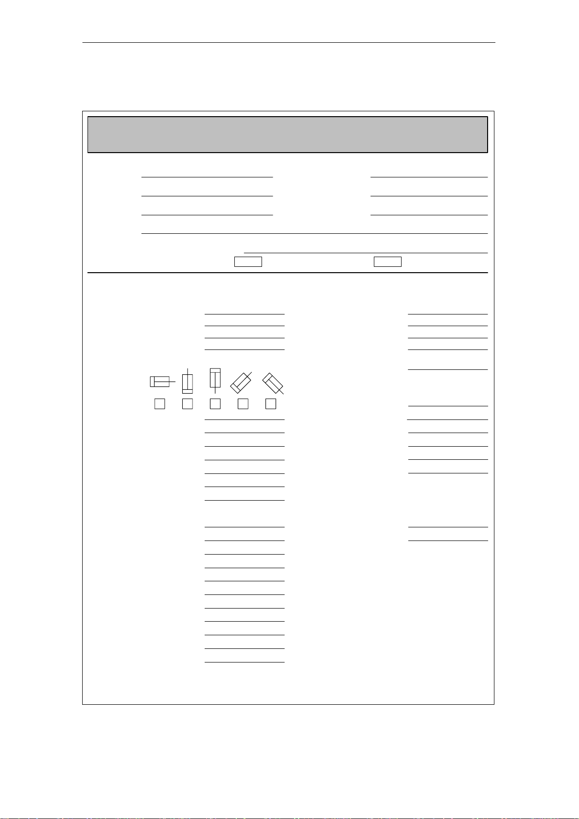
Questionnaire
Company:
Address:
Machine:
Axis: Function/designation:
Straight-cut control: Continuous-path control:
Drive specification
Cylinder dimensions [mm]
Piston diameter:
1st rod diameter:
2nd rod diameter:
Stroke:
Cylinder mounting position: Velocity tolerance
051-001/
Design of hydraulic NC axes
Hydraulic NC axes
Dimensioning of systems with linear motions
Contact person:
Department:
Phone:
Accuracy requirements
Positioning precision [µm]
from rapid traverse:
from feedrate:
Path accuracy:
[mm/min]:
Connection: Position measuring
Valve - cylinder
Pipe/hose length [mm]:
Pipe/hose diameter [mm]:
Moved mass [kg]:
Machining forces [N]
Piston advance:
Piston retraction:
Slide guide friction
µ:
FR [N]:
Pump pressure [bar]:
Velocities [m/min]
Rapid traverse advance:
Rapid traverse retract:
Machining feed advance:
Machining feed retract:
Acceleration rates [m/s2]
Max. acceleration:
Max. delay:
system
Make:
Type:
Other:
Resolution [µm]:
Numerical control
Make:
Type:
incremental,
output signal ...
SIEMENS
840D
Processed by: Dept.: No. of pages: Date:
Siemens AG, 2003. All rights reserved
SINUMERIK 840D/SIMODRIVE 611 digital, HLA Module (FBHLA) - 10.03 Edition
2-23
Page 24

2 Configuration
02.99
10.03
2.2 Integration in SINUMERIK 840D/SIMODRIVE 611 digital
2.2 Integration in SINUMERIK 840D/SIMODRIVE 611 digital
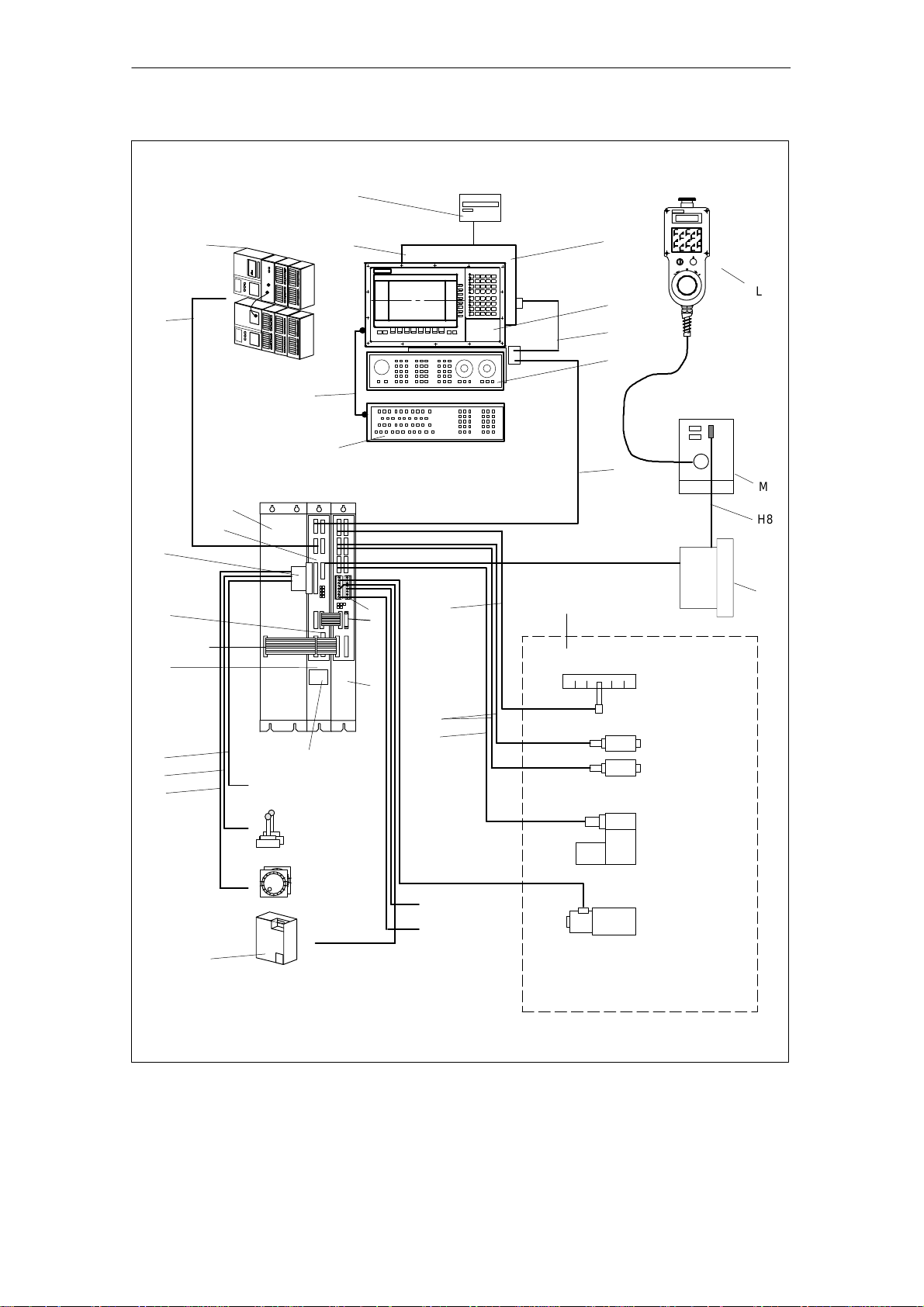
2.2.1 System overview
Components
A complete SINUMERIK 840 digital control system with HLA module consists of
various individual components. These are listed below.
Table 2- 1 Components of SINUMERIK 840 digital control with HLA module (number,
No.in
Fig.
2-3
O NCU box
B NC CPU
component, description)
Component Description
S Enclosure for NC CPU
S Central processing unit of 840D
S Execution of NC program,
S Contains modules with e.g. PLC, communications
functions
S NCU 573.2 includes a fan module
B1 Cable distributor
1)
C
Operator panel
1)
D
MMC module
S For insertion in NCU
S Display, keyboard, power supply unit and
operator controls for NC
S Operator panel calculator (integrated in panel),
S MMC 103 with hard disk
I Mains supply module
(MS)
1)
F
Machine control panel
G11)ISA adapter
G21)Full CNC keyboard
References: /PJ1/ SIMODRIVE 611
S Machine operation
S Allows AT modules to be used in conjunction with
the MMC module MMC103 (mounted in operator
panel)
S Full keyboard for connection to MMC module
G3 Memory card (PCMCIA)
S Contains the system program,
S can be slotted into the NCU 561.2, 571.2, 572.2,
573.2
G4 Diskette unit (accessory)
H1 to
Cable References: /Z/, Catalog of Accessories NC Z
H 9
H10
Cable See Chapter 7, Peripherals/Accessories
to
H12
I SIMODRIVE hydraulics
module (HLA module)
50 mm carrier module
(universal empty housing)
I1 Phoenix cable connection
S Built-in unit for connection to MMC module
S Closed-loop control of hydraulic drive
S Actuation of servo solenoid valve
Holder for HLA closed-loop control plug-in module
(see Fig. 2-6)
S Shutoff valve
S External 24 V supply
S BERO input
S “Power enable”
J SIMATIC components References: /S7H/, Manual
K Terminator Terminator for drive bus (inserted in last module in
drive grouping)
2-24
SINUMERIK 840D/SIMODRIVE 611 digital, HLA Module (FBHLA) - 10.03 Edition
Siemens AG, 2003. All rights reserved
Page 25

10.03
2 Configuration
2.2 Integration in SINUMERIK 840D/SIMODRIVE 611 digital
Table 2-1 Components of SINUMERIK 840 digital control with HLA module (number,
No.in
Fig.
2-3
1)
L
component, description)
Handheld unit
DescriptionComponent
S Connect HHU to K bus via MPI
S Handwheel, EMERGENCY STOP button, key-ac-
tuated switch, override, agreement buttons, dis-
1)
M
Distribution box
play, unassigned keys
S For linking the hand-held unit to the MPI bus
S Connection for EMERGENCY STOP circuit, en-
able keys, handwheel, 24 V DC
N Cable distributor
O Hydraulic Drive References:
P External 24 V supply
1) A description of these components can be found in:
References: /BH/, Operator Components Manual
S 24V supply for connection to MPI connector
/BR1/, “Servo solenoid valves” catalog
/BR2/, “Sensors and electronics” catalog
/BR3/, “Adapter plate valves” catalog
S SITOP stabilized power supply modules
References: SITOP catalog
Order No. E860060-K2410-A101-A4
Note
An HLA module must never be operated directly on a SIMODRIVE monitoring
module, i.e. it must always be connected via a mains infeed module.
For information about connecting further additional SIMODRIVE monitoring
modules in configurations with several HLA modules, please refer to the
Planning Guide for SIMODRIVE 611 Converters /PJU/.
In a multi-tier configuration, all the infeed supply units must be connected
simultaneously.
Siemens AG, 2003. All rights reserved
SINUMERIK 840D/SIMODRIVE 611 digital, HLA Module (FBHLA) - 10.03 Edition
2-25
Page 26
2.2 Integration in SINUMERIK 840D/SIMODRIVE 611 digital
2 Configuration
02.99
10.03
Floppy
G4
J
G1
MMC CPU
D
S7-300
C
L
H1
H5
MCP
F
H4
G2
H6
M
E
B
(GND)
H8
B1
G3
Device bus
A
H2
H3
H9
SITOP power
(external PS)
P
MS
module
HLA
NCU
Battery and plug-in fan
unit
Digital I/O
(high-speed NC I/O)
Measurement (2x)
Handwheel
(2x) (1x of M)
External 26.5 V
supply
I1
H10
O
N
K
I
Position sensing
H11
H12
Pressure sensor A
Pressure sensor B
Servo solenoid
valve
BERO
inputs
Enable
Shutoff valve
Note:
Display of hydraulics for one axis
Fig. 2-3 System components
2-26
SINUMERIK 840D/SIMODRIVE 611 digital, HLA Module (FBHLA) - 10.03 Edition
Siemens AG, 2003. All rights reserved
Page 27
2 Configuration
02.99
10.03
2.2 Integration in SINUMERIK 840D/SIMODRIVE 611 digital
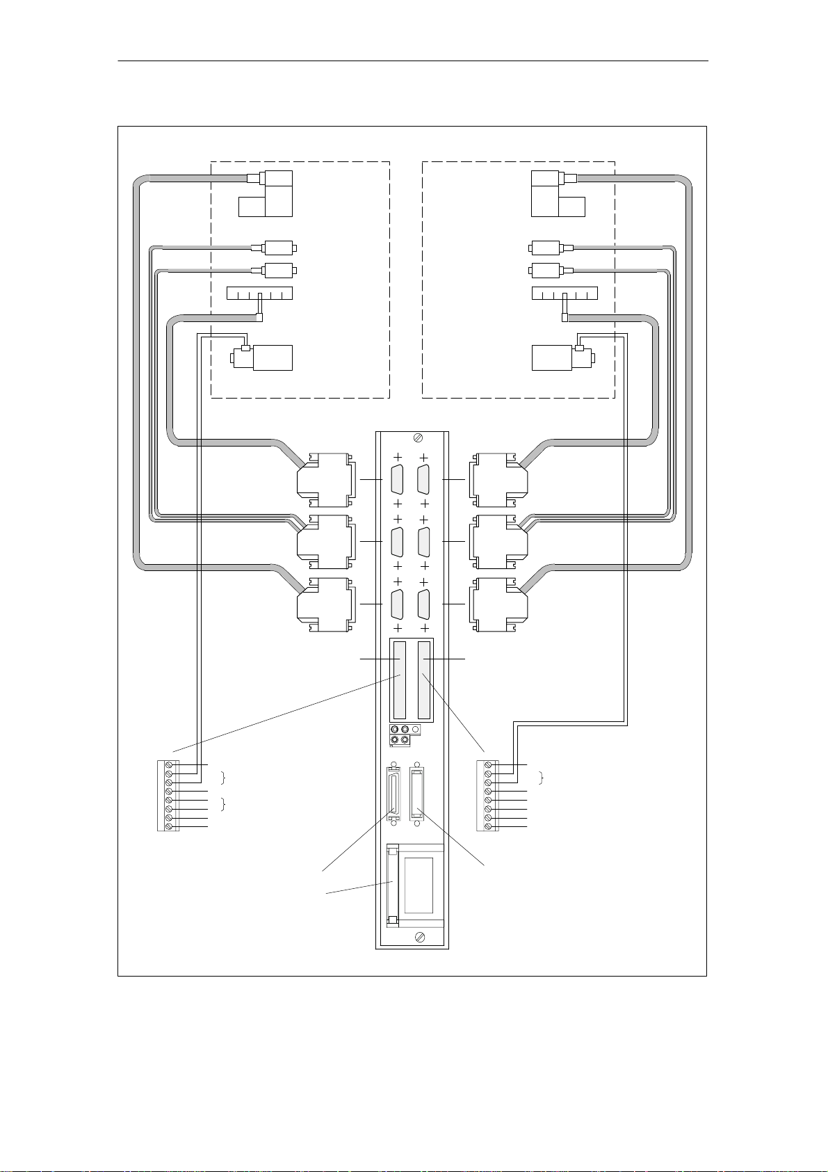
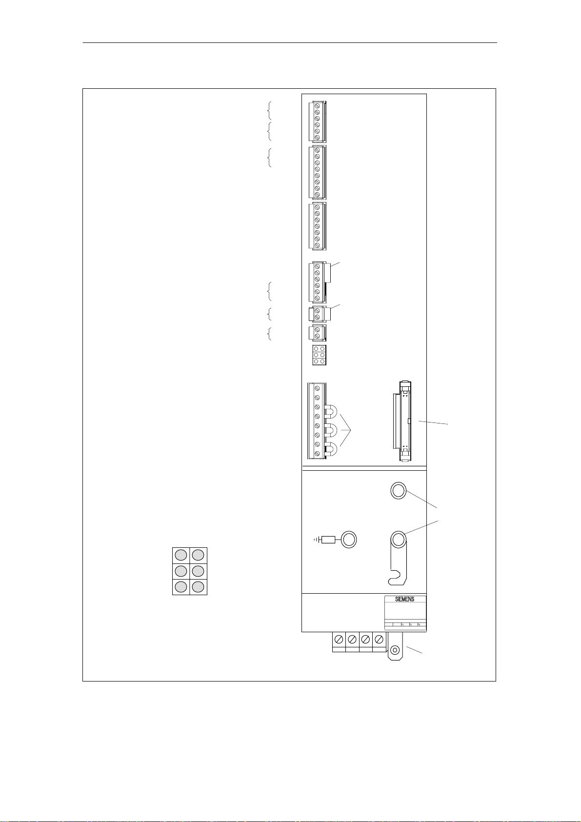
O
B
Hydraulic drive, axis 1
Position
measuring
system
Pressure sensor
Servo solenoid
valve
Pressure
sensor A
Pressure
sensor B
Position sensing
Shutoff valve
Servo solenoid valve
Pressure sensor A
Pressure sensor B
Position sensing
Shutoff valve
O
B
Hydraulic drive, axis 2
Axis 1
HLA
-X101
BOBB
-X102
Axis 2
Position
measuring
system
O
-X111
-X112
Pressure sensor
Servo solenoid
-X121
X431 X432
-X34
M
PV1
MV1
C1
P24
M24
663
9
Functional ground
+
Shutoff valve, axis 1
-
Reserved, do not use!
+
External 26.5 V supply
-
Power enable at term. 663
Internal +24 V enabling voltage
X1141
Drive bus
Device bus interface (X151)
1) Only required if external 26.5 V is not electrically separated safely!
Fig. 2-4 Connection configuration for HLA module
-X35
-X122
X1341
Servo solenoid
valvevalve
M
PV2
MV2
C2
B1
19
B2
9
Functional ground
+
Shutoff valve, axis 2
-
Reserved, do not use!
BERO input, axis 1
Internal 0 V enabling voltage
BERO input, axis 2
Internal +24 V enabling voltage
Drive bus/drive bus terminator on last
module
1)
Siemens AG, 2003. All rights reserved
SINUMERIK 840D/SIMODRIVE 611 digital, HLA Module (FBHLA) - 10.03 Edition
2-27
Page 28
2.2 Integration in SINUMERIK 840D/SIMODRIVE 611 digital
2 Configuration
02.99
10.03
Relay contact,
Ready to operate
message
Relay contact for group message
2
t and motor overtemperature
I
Reference potential for enable voltage
Enabling signal for internal line contactor
Signaling contact for starting lockout (NC contact)
DC link power supply for bridging line failures
Electronics power supply from external source
Electronics power supply from external source
Electronics power supply from external source
Power disable
Enabling voltage
Enabling voltage
Drive enable
P24
P15
N15
N24
M
M
RESET (R+term.15)
Enabling voltage
Setup mode
Contactor energization, start
Signaling contact,
line contactor
NC
contact
NO
contact
74
73.1
73.2
72
5.3
5.2
5.1
63
9
9
64
19
7
45
44
10
15
15
R
9
112
48
111
213
113
NS1
NS2
AS1
AS2
M500
P500
2U1
1U1
2V1
1V1
2W1
1W1
X111
X121
X141
1)
X161
1)
X171
X172
LED displays
X181
1)
X351
Device bus
LED displays
Electronics power
supply faulty
Device is not ready,
no enable signal
(term. 63, 64 or 48)
Line fault
Red
Green
Red
Red
Yellow
Red
5 V voltage level
fault
Device ready
(DC link
precharged)
DC link
overvoltage
1) Jumpers inserted in delivery state
Fig. 2-5 Interfaces on mains supply module (OI and I/RF module)
P600
DC link
connection
M600
Power supply
U1 V1 W1 X131 PE
2-28
SINUMERIK 840D/SIMODRIVE 611 digital, HLA Module (FBHLA) - 10.03 Edition
Siemens AG, 2003. All rights reserved
Page 29
10.03
2 Configuration
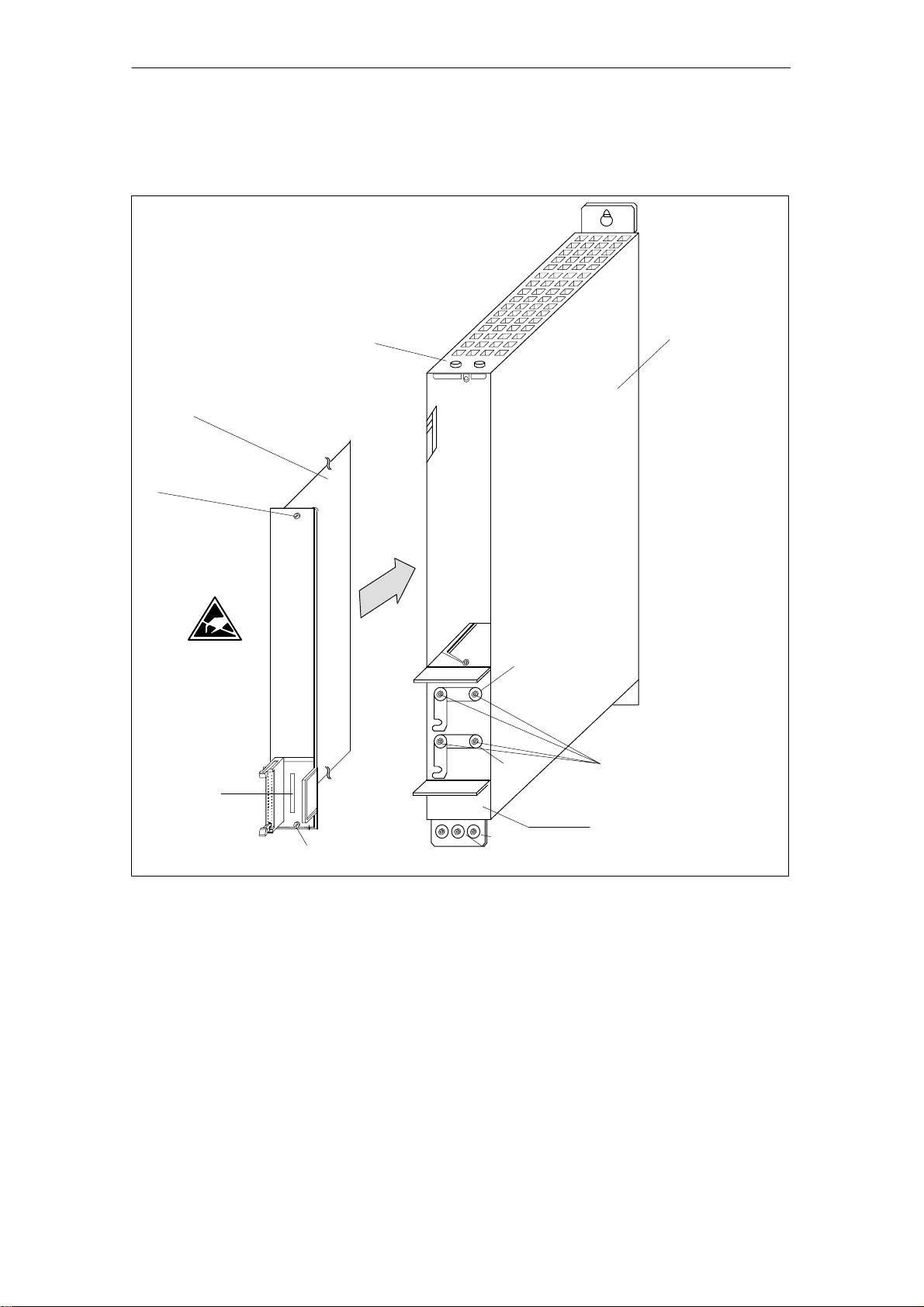
Mounting the HLA
closed-loop control
plug-in module
HLA closed-loop control plug-in
module (6SN1115-0BA11-0AA1)
Slotted screw
M3 / 0.8 Nm
2.2 Integration in SINUMERIK 840D/SIMODRIVE 611 digital
Shield connection
50 mm carrier module
(universal empty housing)
(6SN1162-1AA00-0AA0)
P600
M600
Order No.
Slotted screw
M3 / 0.8 Nm
Fig. 2-6 Mounting the HLA closed-loop control plug-in module in 50 mm carrier module (universal empty housing)
PE
M5 / 3.0 Nm
M4 / 1.8 Nm
Rating plate/Order No.
2.2.2 Required FW packages
S SINUMERIK 840D NCK SW w5.1
including SIMODRIVE 611 digital HLA module w1.0
S SINUMERIK 840D MMC SW u5.1
or
SINUMERIK 840D HMI SW w6
2.2.3 Hardware requirements
S NCU 561.2, 571.2, 572.2, 573.2
Siemens AG, 2003. All rights reserved
SINUMERIK 840D/SIMODRIVE 611 digital, HLA Module (FBHLA) - 10.03 Edition
2-29
Page 30

2.3 Configuring the hydraulic drive
2 Configuration
2.3 Configuring the hydraulic drive
10.03
General
Hydraulic drives are generally configured by technical sales personnel from the
hydraulics supplier, Rexroth.
The configuration is based on the data from the questionnaire in
Subsection 2.1.2 .
Please refer to Appendix A for a description of hydraulic components.
The hydraulic drive is configured in the sequence of steps described below.
2.3.1 Cylinder selection
Piston and rod
diameter
The piston and rod diameters are calculated according to Pascal’s theorem on
the basis of the necessary compressive and tensile forces F and a standard
pressure value of P=40...100 bar for machine tools (a maximum pressure setting of 350 bar is permitted).
The force value calculation must include friction and acceleration forces
as well as the actual feed force. Pistons and rods with the following standard
diameter dimensions are available:
Table 2-2 Typical cylinder data
Description Diameter
Piston ∅ 25 32 40 50 63 80 100 125
Rod ∅ Standard 12 14 18 22 28 36 45 56
Rod ∅ Optional 18 22 28 36 45 56 70 90
p =
F
O
Stroke length
2-30
The stroke is identical to the working stroke of the drive except that
it includes a few additional safety reserves.
SINUMERIK 840D/SIMODRIVE 611 digital, HLA Module (FBHLA) - 10.03 Edition
Siemens AG, 2003. All rights reserved
Page 31

10.03
2 Configuration
2.3 Configuring the hydraulic drive
Mounting
Mounting position
In order to ensure good control quality, backlash-free mountings, e.g. base or
flange mountings, must be used.
Flange mounting
Flange at front Flange at rear
Base mounting
Fig. 2-7 Cylinder mounting methods
This is will depend on the machine’s situation and affects the choice of shutoff
valves (see Subsection 2.3.3). Vertical loads must be protected via poppet
valves. Forces due to weight must be taken into account in the final calculation
of the operating pressure (MD 5151: CYLINDER_A_ORIENTATION).
See Fig. 4-17 in Section 4.9 for the possible cylinder mounting positions.
Seal, friction
Cylinder pipes
Position
measuring system
Suitable seals must be used to minimize friction. Transitions from static to sliding friction have a particularly adverse affect on the control result.
The slide guide friction must be added to the cylinder friction. A friction compensation setting has been provided in the HLA module (MD 5460:
FRICTION_COMP_GRADIENT) for the purpose of counteracting initial friction.
The distance between the cylinder and servo solenoid valve must be kept as
short as possible for the sake of the drive’s natural frequency (compressibility of
the oil volume). In ideal cases, the servo solenoid valve is flange-mounted
directly on the cylinder.
The incremental and absolute position measuring systems supported by the
HLA module are mounted on the machine slide. It is also possible to use position measuring systems (SSI encoders) integrated in the cylinder.
Siemens AG, 2003. All rights reserved
SINUMERIK 840D/SIMODRIVE 611 digital, HLA Module (FBHLA) - 10.03 Edition
2-31
Page 32

2.3 Configuring the hydraulic drive
2 Configuration
2.3.2 Selection of servo solenoid valves
References: /BR1/, “Servo solenoid valves” catalog
Valve types
(overview)
Table 2-3 Overview of servo solenoid and HR servo solenoid valves from Bosch Rexroth AG
The HLA module supports servo solenoid valves with on-board electronics
(OBE) supplied by Bosch Rexroth AG. The technical data for these valves and
valves supplied by other manufacturers is stored in the HLA module software.
The drive is parameterized automatically when the order number is entered.
The following table lists the various types of servo solenoid valve and HR (=
High Response) servo solenoid valves available from Bosch Rexroth AG.
For a complete list, please see Tables 2-4 to 2-10.
10.03
Title Nomi-
4WRPEH
(directly-controlled
servo solenoid valve)
4WRPE
(pilot-controlled
servo solenoid valve)
4WRPEH
(directly-controlled
HR servo solenoid valve)
nal
size
6 up to 40 / 35 bar linear and
10 up to 100 / 35 bar linear and
10 up to 70 / 5 bar with knee 40
16 up to 150 / 5 bar with knee 40
6 up to 40 / 35 bar linear and
Nominal flowrate (l/min)
for nominal pressure drop
per control edge (bar)
curve Limit fre-
110
with knee
with knee
210
with knee
quency
1)
85
(Hz)
4WRVE
(pilot-controlled
HR servo solenoid valve)
1) The characteristic values specified for the valve limit frequencies relate to an amplitude of "5% and a
phase offset in the Bode diagram of -90°, see also data in catalog supplied by Bosch Rexroth AG.
2-32
SINUMERIK 840D/SIMODRIVE 611 digital, HLA Module (FBHLA) - 10.03 Edition
10 up to 70 / 35 bar with knee 80
16 up to 150 / 5 bar with knee 80
Siemens AG, 2003. All rights reserved
Page 33

10.03
2 Configuration
2.3 Configuring the hydraulic drive
The choice of valve for a particular application is made with reference to the
following criteria.
Servo solenoid or
HR servo solenoid
valves
Valve size
HR (High Response) valves are characterized by their improved dynamic quality, i.e. by a higher limit frequency compared to servo solenoid valves. They
react with greater sensitivity to setpoint changes especially in the small-signal
range. The use of HR servo solenoid valves is recommended in the following
cases:
1. When extremely high contour precision is required in high-speed continuous-path control machining operations.
2. When very high response sensitivity is required to achieve the best possible
positioning accuracy.
Note that HR servo solenoid valves do not generally have a fail-safe position.
The connector is also 12-pin, rather than 7-pin as with servo solenoid valves.
The valve size is determined by the maximum flowrate Q
. This maximum flow-
X
rate is calculated according to the law of flow:
=v @ A
Q
X
v: Maximum drive speed for extension and retraction
A: associated cylinder surface area
The calculated maximum flow rate must not exceed the limit for use of the
valve. This limit is generally specified in the catalog by the valve manufacturer
(e.g. Rexroth: /BR1/, “Servo solenoid valves” catalog).
Within the limits for use, the flow rate that can be achieved with the valve is calculated by
Q=Q
nom
@
p
p
nom
Linear/knee-shape
d flowrate
characteristic
In practice, the cylinder speeds that can actually be achieved depend on the
operating pressure, the load pressure and flow-specific characteristics of the
drive. The dimensioning is left to the hydraulic configuration engineer, who has
access to a number of design calculation and simulation programs.
V alues with either a linear or knee-shaped characteristic can be selected.
The latter are suitable for obtaining a higher resolution in the low signal range
(machining) and sufficient flow in the high signal range (rapid traverse).
The definition of the knee-point position as 40% or 60% means that only 10% of
the nominal opening cross-section (nominal flowrate) is released at 40% or 60%
of the nominal control signal (i.e. at U=4 V or 6 V).
The knee-shaped characteristic of the valve must be linearized in the HLA module to adapt it to the closed-loop control of the entire drive (cylinder).
Siemens AG, 2003. All rights reserved
SINUMERIK 840D/SIMODRIVE 611 digital, HLA Module (FBHLA) - 10.03 Edition
2-33
Page 34

2.3 Configuring the hydraulic drive
2 Configuration
10.03
Q/Q
nom
Rapid traverse
10%
40%
Fig. 2-8 Diagram of a knee-shaped servo solenoid valve characteristic and its correction in the HLA module
U/U
nom
Machining velocity
10%
Q/Q
nom
40%
Valve characteristic
Linearized
characteristic
U/U
nom
compensation
Note
Recommended selection:
Servo solenoid valves are generally recommended for applications where there
is a clear separation between machining operation and rapid traverse.
Asymmetrical
flowrate
characteristics
It is a good idea to use valves with asymmetrical restriction cross-sections for
differential cylinders or for cylinders that are not arranged horizontally and move
large loads. This improves the hydraulic clamping of the cylinder and adjusts
the controlled system gain of the hydraulic servo-drive for both directions of
travel.
Q
A
P
A
P
B
Q
OB
PT
Fig. 2-9 Asymmetrical characteristics
B
Q
v
U
G
2-34
SINUMERIK 840D/SIMODRIVE 611 digital, HLA Module (FBHLA) - 10.03 Edition
Siemens AG, 2003. All rights reserved
Page 35

10.03
2 Configuration
2.3 Configuring the hydraulic drive
Fail-safe position
Pin assignments
Directly-controlled servo solenoid valves have a fail-safe position, i.e. the control
spool moves to a safe position when the valve is disconnected from the power
supply. The fail-safe position is either “closed” (A, B, P, T disabled) or “open” (A,
B and T connected and P disabled). It should be noted that the “crossed”
switching position is necessarily passed when the valve is switched on and off,
and there can be temporary responses from the cylinder at these moments.
Separate shut-off valves are therefore required in order to implement safety
functions, such as a totally safe cylinder stop.
Pilot-controlled servo solenoid valves, pilot-controlled HR servo solenoid valves
and directly-controlled HR servo solenoid valves do not have a fail-safe position
and thus do not have a safe basic position when switched off. Any safety functions nmust therefore be implemented via separate shut-off valves.
Fail-safe closed Fail-safe open
OB
PT
Fig. 2-10 Fail-safe position in the valve graphical symbol
OB
PT
A distinction must be made between servo solenoid valves and HR servo solenoid valves.
S Servo solenoid valves (directly and pilot-actuated): 7-pin round connector
2.5 AF
+24 V=O
B
C
100k
100k
10k
Fig. 2-11 Connector pin assignment on servo solenoid valves
D
I
F
0 V
0 V
Sign.
Supply
Reference point for actual
valve spool value
Setpoint 0..."10 V
Actual value spool value
Protective
conductor
Shield
Siemens AG, 2003. All rights reserved
SINUMERIK 840D/SIMODRIVE 611 digital, HLA Module (FBHLA) - 10.03 Edition
2-35
Page 36

2.3 Configuring the hydraulic drive
OB
PT
PT
PT
PT
2 Configuration
S HR servo solenoid valves (directly and pilot-controlled); 12-pin round
connector
+U
B
100k
100k
10k
10
11
10.03
2.5 AF
+24 V=
0 V
1
2
3
4
5
6
7
8
9
24 V
Sign.
0 V
24 V
+24 V =/v0.5 A
0 V
24 V
Output stage supply
enabling of
Setpoint 0..."10 V
Actual value spool value
Enable acknowledgement
Electronics supply
Error message
Protective
conductor
Shield
Fig. 2-12 Connector assignment for HR servo solenoid valves
Preferred range
of servo solenoid
valves
Table 2-4 NG6 directly-controlled servo solenoid valves; model code 4WRPEH 6
HLA
code
no.
10 0 811 404 601 12 Linear.
11 0 811 404 602 24 Linear.
12 0 811 404 603 40 Linear.
13 0 811 404 610 4 Linear. OB
14 0 811 404 611 12 Linear.
15 0 811 404 612 24 Linear.
16 0 811 404 613 40 Linear.
17 0 811 404 642 15 60
18 0 811 404 747 25 60
19 0 811 404 644 40 40
20 0 811 404 645 15 60 OB
21 0 811 404 646 25 60
22 0 811 404 647 40 40
Rexroth
order number
9 0 811 404 600 4 Linear. 7-pin
The following tables list all the servo solenoid valves and HR servo solenoid
valves supplied by Bosch Rexroth AG for which technical data is stored in the
HLA module.
Q
nom
(l/min) for
np / edge
= 35 bar
Character-
istic kneep-
oint (%)
No. of
connector pins
Graphic symbol Rexroth
OB
OB
PT
PT
catalog
/BR1/
2-36
SINUMERIK 840D/SIMODRIVE 611 digital, HLA Module (FBHLA) - 10.03 Edition
Siemens AG, 2003. All rights reserved
Page 37

10.03
2 Configuration
2.3 Configuring the hydraulic drive
Table 2-4 NG6 directly-controlled servo solenoid valves; model code 4WRPEH 6
HLA
code
no.
Rexroth
order number
Q
nom
(l/min) for
np / edge
Character-
istic kneep-
oint (%)
connector pins
Graphic symbolNo. of
= 35 bar
23 0 811 404 648 A:40; B:20
1)
40 7-pin
OB
PT
24 0 811 404 649 A:40; B:20
1)
40 OB
PT
Table 2-5 NG10 directly-controlled servo solenoid valves; model code 4WRPEH 10
HLA
code
no.
Rexroth
order number
Q
nom
(l/min) for
np / edge =
Character-
istic kneep-
oint (%)
No. of
connector pins
Graphic symbol Rexroth
35 bar
41 0 811 404 800 50 Linear. 7-pin
OB
42 0 811 404 801 100 Linear.
PT
43 0 811 404 802 50 Linear. OB
Rexroth
catalog
/BR1/
catalog
/BR1/
44 0 811 404 803 100 Linear.
45 0 811 404 822 50 40
46 0 811 404 823 100 40
47 0 811 404 824 50 40 OB
48 0 811 404 825 100 40
B:50
B:50
1)
1)
1)
1)
40 OB
40
40 OB
40
49 0 811 404 826 A:50; B:25
50 0 811 404 827 A:100;
51 0 811 404 828 A:50; B:25
52 0 811 404 829 A:100;
1) Asymmetrical characteristic
PT
OB
PT
PT
PT
PT
Siemens AG, 2003. All rights reserved
SINUMERIK 840D/SIMODRIVE 611 digital, HLA Module (FBHLA) - 10.03 Edition
2-37
Page 38

2.3 Configuring the hydraulic drive
s
u
s
u
PTX Y
s
u
s
u
PTX Y
OB
PT
PT
OB
PTX Y
PTX Y
2 Configuration
Table 2-6 NG10 pilot-controlled servo solenoid valves; model code 4WRLE 10
10.03
HLA
code
no.
Rexroth
order number
Q
nom
(l/min) for
np / edge =
Character-
istic kneep-
oint (%)
No. of
connector pins
Graphic symbol Rexroth
5 bar
25 0 811 404 686 40 40 7-pin
OB
26 0 811 404 687 70 40
27 0 811 404 688 A:40; B:20
28 0 811 404 689 A:70; B:40
1)
1)
40
40
X Y
PT
Table 2-7 NG16 pilot-controlled servo solenoid valves; model code 4WRLE 16
HLA
code
no.
Rexroth
order number
Q
nom
(l/min) for
np / edge =
Character-
istic kneep-
oint (%)
No. of
connector pins
Graphic symbol Rexroth
5 bar
1 0 811 404 263 90 40 7-pin
OB
2 0 811 404 264 150 40
B:90
1)
1)
40
40
X Y
PT
3 0 811 404 265 A:90; B:50
4 0 811 404 266 A:150;
Table 2-8 NG6 directly-controlled HR servo solenoid valves; model code 4WRREH 6
catalog
/BR1/
catalog
/BR1/
HLA
code
no.
Rexroth
order number
Q
nom
(l/min) for
np / edge =
Character-
istic kneep-
oint (%)
No. of
connector pins
Graphic symbol Rexroth
35 bar
33 0 811 404 720 40 Linear. 12-pin
OB
34 0 811 404 721 24 Linear.
35 0 811 404 722 12 Linear.
36 0 811 404 723 8 Linear.
37 0 811 404 725 15 60
38 0 811 404 726 25 60
39 0 811 404 727 40 40
40 0 811 404 728 A:40; B:20
1)
40
Table 2-9 NG10 pilot-controlled HR servo solenoid valves; model code 4WRVE 10
HLA
code
no.
Rexroth
order number
Q
nom
(l/min) for
np / edge =
Character-
istic kneep-
oint (%)
No. of
connector pins
Graphic symbol Rexroth
5 bar
29 0 811 404 693 40 40 12-pin
OB
30 0 811 404 694 70 40
31 0 811 404 695 A:40; B:20
32 0 811 404 696 A:70; B:40
1)
1)
40
40
catalog
/BR1/
HRV - Size 6
catalog
/BR1/
1) Asymmetrical characteristic
2-38
SINUMERIK 840D/SIMODRIVE 611 digital, HLA Module (FBHLA) - 10.03 Edition
Siemens AG, 2003. All rights reserved
Page 39

10.03
OB
PTX Y
PTX Y
2 Configuration
2.3 Configuring the hydraulic drive
Table 2-10 NG16 pilot-controlled HR servo solenoid valves; model code 4WRVE 16
HLA
code
no.
1) Asymmetrical characteristic
Rexroth
order number
5 0 811 404 296 90 40 12-pin
6 0 811 404 297 150 40
7 0 811 404 298 A:90; B:50
8 0 811 404 299 A:150;
Q
nom
(l/min) for
np / edge =
5 bar
1)
B:90
Character-
istic kneep-
1)
oint (%)
40
40
2.3.3 Selection of shutoff valves
References:/BR3/, “Adapter plate valves” catalog
General
!
The shutoff valves are automatically enabled and disabled in the correct switching sequence by the HLA module.
Start condition: The hydraulic pressure must be available before
the system is switched on.
Warning
In the event of sudden failure (e.g. open circuit) of the external 24 V supply, an
axial storage capacitor on the HLA module provides energy to supply the servo
solenoid valve until such time as the pressure supply for a configured shutoff
valve is disabled.
The machine manufacturer must verify the interaction between valves, making
allowance for all tolerances in the controlled system.
The energy content of the storage capacitors is dependent upon
No. of
connector pins
Graphic symbol Rexroth
OB
catalog
/BR1/
S the tolerances of the capacitors,
S the voltage level of the external supply and
S the charging time of the integrated capacitors (instant of voltage failure).
The available response time is mainly defined by
S the power required for the current machining step,
S the response time of the shutoff valves and
S the trip threshold of the servo solenoid valves.
Siemens AG, 2003. All rights reserved
SINUMERIK 840D/SIMODRIVE 611 digital, HLA Module (FBHLA) - 10.03 Edition
2-39
Page 40

2.3 Configuring the hydraulic drive
2 Configuration
10.03
Examples
Figure 2-13 shows an electrically-switched sandwich-type shut-off valve used to
shut off the system pressure at the servo solenoid valve.
Interruption of the hydraulic power circuit upstream of the servo solenoid valve
is sufficient to meet simple safety requirements. When a servo solenoid valve in
the closed fail-safe position is switched off, then approximate shut-off of the consumer connections with respect to the cylinder is guaranteed.
There are some safety limitations, however, since the servo solenoid valve’s
fail-safe position is not totally free of leakage oil, and thus does not work without
some cylinder drift. In addition, when the servo solenoid valve is switched on
and off, the “crossed” position is necessarily passed, which can result in cylinder movement.
OB
b
S
PT
a
T BOP
U
Servo
solenoid
valve
Shut-off valve
(electrically
switched)
Fig. 2-13 A typical example for an electrically-controlled shut-off valve
The circuit in Figure 2-14 achieves a high level of safety. In this case, an additional barrier block closes the consumer connections to the cylinder safely and
with no leakage of oil. This means that even heavy loads on non-horizontal axis
can be quickly stopped and held safely, regardless of the state of the servo solenoid valve. Totally safe scenarios for switching the drive on and off can thus
be implemented.
OB
b
S
PT
a
T BOP
U
Servo
solenoid
valve
Shutoff valve
(barrier block)
Shutoff valve
(electrically
switched)
2-40
Fig. 2-14 Typical example for the combination of an electrically-switched shut-off valve
with an additional barrier block
SINUMERIK 840D/SIMODRIVE 611 digital, HLA Module (FBHLA) - 10.03 Edition
Siemens AG, 2003. All rights reserved
Page 41

10.03
2 Configuration
2.3 Configuring the hydraulic drive
Preferred range
of shut-off valves
Table 2-11 Shutoff valves
Rexroth
order number
0 811 024 120 6
0 811 020 040 10
0 811 024 125 6
0 811 024 123 6
Nominal
size
Bosch Rexroth shut-off valves from the following table should ideally be used
in conjunction with the HLA module. These are sandwich-plate valves in sizes 6
and 10. Additional shut-off valves are available upon request from Bosch Rexroth.
Graphic symbol Rexroth
P
’
a
P TOB
P
’
P
P
’
T’ A’ B’
T’ A’ B’
TOB
T’ A’ B’
b
catalog
/BR3/
0 811 004 102 6
0 811 004 103 6
0 811 004 104 6
0 811 024 122 6
0 811 024 121 6
P
A
’
a
O
A
’
b
O
B
T
’
’
B
A
’
a
O
P
’
A
’
B
’
B
T
’
T
a
B
’
TOB
P’ T’
PT
B’ P’
BP
A’ P’
OPT
T’ P’
b
TPB
B’ T’
P
Siemens AG, 2003. All rights reserved
SINUMERIK 840D/SIMODRIVE 611 digital, HLA Module (FBHLA) - 10.03 Edition
BTO
2-41
Page 42

2.3 Configuring the hydraulic drive
2 Configuration
2.3.4 Natural frequency of the hydraulic drive
10.03
Servo gain
Natural frequency
The possible servo gain is essentially determined by the natural frequency of
the cylinder and its load ω
ω
.
v
The cylinder and its load constitute a spring/mass attenuation system whose
natural frequency is calculated using the following formula:
wo X
Where: E=modulus of elasticity (N/m2)
Oil volumes in the cylinder pipes must also be taken into account.
The minimum natural frequency occurs only at a particular mid-position about
the middle and increases as the end positions are approached.
The natural frequency of the hydraulic drive is automatically calculated by the
HLA module and applied in the controller once the corresponding data parameters have been set. See machine data, Sections 4.8 and 4.9:
and the limit frequency of the servo solenoid valve
0
A
4 @ E @ A
m @ h
A=piston area (m
AR=ring surface (m2)
h=stroke (m)
α=surface ratio AR/A
m=mass (kg)
1 + α
( )
2
O
h
2
)
R
m
Possible
dynamic response
S MD 5131: CYLINDER_PISTON_DIAMETER
...
MD 5136: CYLINDER_DEAD_VOLUME_B
S MD 5140: VALVE_CYLINDER_CONNECTION
...
MD 5143: PIPE_INNER_ DIAMETER_A_B
S MD 5150: DRIVE_MASS
...
MD 5152: CYLINDER_FASTENING
S MD 5160: PISTON_POS_MIN_NAT_FREQ
...
MD 5163: DRIVE_NATURAL_FREQUENCY
The dynamic response of the servo solenoid valves thus depends on the amplitude of the valve modulation. For valves that are used in controlled axes, the
natural frequency is typically determined for a modulation amplitude of "10%
and a phase offset of -180°. The relevant information is given in the valve
manufacturer’s catalog, e.g. /BR1/.
For pilot-controlled servo solenoid valves, the dynamic response is determined
by the pilot pressure p
The Rexroth catalog data relates to a pilot pressure of 100 bar.
Servo valves can reach corner frequencies of up to 1000 Hz, but are very sensi-
tive to contamination.
, in addition to the valve type:
pilot
fp
~
before0
2-42
SINUMERIK 840D/SIMODRIVE 611 digital, HLA Module (FBHLA) - 10.03 Edition
Siemens AG, 2003. All rights reserved
Page 43

10.03
2 Configuration
2.3.5 Hydraulic power unit
The hydraulic power is supplied by a hydraulic power unit installed separately or
integrated in the machine. The power unit is configured individually to meet the
requirements of all hydraulic loads. The following factors are of particular importance:
2.3 Configuring the hydraulic drive
Pressure p
Flow rate Q
Drive power P
Pump type
The pressure is determined from the cylinder geometry, hydraulic characteristics
of the servo solenoid valve and other data such as load forces or flow resistance values in the hydraulic circuit due to the drive speeds and forces required.
The standard value for the system pressure for machine tool feed drives is
around 40... 100 bar.
The maximum flowrate is calculated from the rapid traverse velocity.
If several cylinders are operating simultaneously, the sum of all loads must be
taken into account.
Maximum flow is often reached for only brief periods and can be supplied by an
accumulator.
The pump capacity is selected to satisfy the mean flow rate.
The power P output by the electric motor to the pump drive is calculated as the
product of pressure p, flow rate Q and efficiency η.
P=p@Q@η
Variable displacement pumps with pressure regulators in combination with an
accumulator are generally employed in order to prevent power losses and to
match the energy supply to the fluctuating delivery requirement during the cycle.
Vane pumps have proven successful in the normal pressure range for these
applications of 70 to 210 bar.
Axial piston pumps are commonly used for high-pressure applications up to 350
bar.
Filtration
Siemens AG, 2003. All rights reserved
SINUMERIK 840D/SIMODRIVE 611 digital, HLA Module (FBHLA) - 10.03 Edition
Classic servo-valves with fluid converters as initial stages are extremely sensitive to contamination. However, even the control edges of modern servo solenoid valves require filtration.
To ensure general operational reliability, but more importantly, to protect the control edges against premature erosion and to maintain the quality of zero overlap,
the oil contamination must be limited in compliance with
Class 7...9 according to NAS 1638.
This is achieved by using class β
in the pressure line directly upstream of the servo solenoid valve.
The most critical phase is start-up, since contamination which has “accumulated” prior to installation often causes failures. For this reason, it is advisable to
purge the system before the servo solenoid valves are fitted.
=75 full flow filters, which must be positioned
10
2-43
Page 44

2.3 Configuring the hydraulic drive
2 Configuration
10.03
Cooling
Since considerable power losses that cannot be compensated for solely
through oil reservoir dissipation occur when the flow is throttled via the control
edges on the valve, additional oil/air or oil/water heat exchangers must be provided in most cases.
P
Q
M
(GND)
°C
Variable displacement pump with pressure regulator
Pressure-relief valve (protection)
Accumulator with fail-safe circuit
Filters in pressure line
Filters in return line
Oil/water heat exchanger
Oil reservoir
Fig. 2-15 Overview of typical hydraulic power unit
2-44
SINUMERIK 840D/SIMODRIVE 611 digital, HLA Module (FBHLA) - 10.03 Edition
Siemens AG, 2003. All rights reserved
Page 45

2 Configuration
04.00
10.03
2.4 Connection
2.4.1 Internal power supply
Comments
Note
The NC CPU is supplied by the SIMODRIVE power supply via the device bus.
No provision has been made for any other type of voltage supply and failure to
use the supply provided could damage the unit.
2.4 Connection
Connection and
power loss
calculation for the
NCU
The HLA module is integrated as a single module into the network of
SIMODRIVE modules (power supply or incoming supply module, possibly feed
modules and/or main spindle modules) and 840D. The power supply is fed in
via the device bus.
The total power requirement for the entire network must be calculated. This
must not exceed the power supplied by the power supply module.
To make the calculation easier, each module has a weighting factor.
This can be found in Chapter 9 of the following reference material:
References: NC 60 catalog
The sum of electronic and control points must not be larger than stated in the
data sheet of the power supply module.
2.4.2 External power supply
Requirements of
external 26.5 V
supply
The purpose of the external power supply is to switch and supply the hydraulic
components
S closed-loop proportional valves
S Shutoff valves
S pressure sensors
via the closed-loop control.
In principle, stabilized or unstabilized power supplies and switched-mode or
in-phase-controlled supplies can be used.
The following points must, however, be noted:
S The required voltage tolerance can only be achieved in practice with stabi-
lization and preferably switched for the existing currents. The ripple associated with an unstabilized power supply may cause tripping at the lower monitoring threshold.
S The stabilization has 24000 µF input capacity per module, which can best
be charged up with a stabilized power supply (with current limitation).
Siemens AG, 2003. All rights reserved
SINUMERIK 840D/SIMODRIVE 611 digital, HLA Module (FBHLA) - 10.03 Edition
2-45
Page 46

2.4 Connection
2 Configuration
!
02.99
10.03
Warning
S The DC supply must be safely electrically isolated.
See also:
References: /PHD/, Configuration NCU 561.2-573.2
S The DC supply must be connected to the functional ground of the control at
one point (e.g. X131 on I/RF module). As a rule, the connection is provided
as standard in the S7-300 I/Os. See also:
References: /EMC/, SINUMERIK, SIROTEC, SIMODRIVE, EMC
Installation Guideline
S The input for the 26.5 V supply is protected against polarity reversal.
26.5 V "2% must be fed from the external 26.5 V supply to connector X431
to supply the hydraulics components (servo solenoid valves, shut-off valves,
and pressure sensors). The power requirements is calculated from the
power required by external components plus 0.1 A for the internal circuit.
The input voltage tolerance relates to the input terminals of the closed-loop
control; the voltage drops on the supply leads are not negligible.
The external 26.5 V supply is monitored for violation of a lower limit in the
control.
Caution
!
After the external 26.5 V supply has powered up, terminal X431 may no longer
be inserted or switched since the high charging currents can irreparably
damage the module or external switch.
S If the external 26.5 V supply has to be switched, then an external “precharg-
ing circuit” (e.g. relay with timer and resistor) must be used.
S The 26.5 V outputs are short-circuit-proof or protected by fuses.
The outputs for the shutoff valves are designed as electronic switches with
integrated zener diodes for disconnecting inductive loads. The zener diodes
are located between the 24 V input and the output, with a typical zener voltage of 58 V.
On supply disconnection, the energy produced by the coil inductance and
the valve spool spring, plus the energy supplied from the 24 V source in the
zener diode and ohmic resistance in the solenoid coil is converted to heat.
This energy must not exceed 1.7 J during one power OFF process or else
the zener diode will be destroyed; no electronic protection against this type
of overload is available.
S Other requirements of the external 26.5 V supply:
- Voltage range (mean value) 25.97 V to 27.03 V DC
- Ripple 240 mVpp
- No voltage dips, otherwise disconnection
2-46
SINUMERIK 840D/SIMODRIVE 611 digital, HLA Module (FBHLA) - 10.03 Edition
Siemens AG, 2003. All rights reserved
Page 47

10.03
(24...28.8 V)
tol. "1%
tol. "1%
2 Configuration
2.4 Connection
Recommended
power supply
The SITOP power product range supplied by SIEMENS is recommended for
use as the external 26.5 V power supply.
References: SITOP catalog
Order no. E86060-K2410-A101-A4
S SITOP power for line supply connection
The SITOP power product types shown in the tables are recommended for
the line supply connection:
Table 2-12 SITOP power for line supply connection
Input Output Order No.
Voltage range
[v]
2AC 85...132/176...550 24 V DC
3AC 320...550
Mains supply module
Voltage
U
a
X431
5
6
HLA module
P24EXTIN
M24EXTIN
Current
I
a Nom
5 A 6EP1333-3BA00
10 A 6EP1334-3BA00
20 A 6EP1436-3BA00
40 A 6EP1437-3BA00
X131
L1
SITOP
Line
Fig. 2-16 Connection of external 26.5 V SITOP power for line connection
L2
L3
PE
AC/DC
M (GND)
L+ (26.5 V)
Siemens AG, 2003. All rights reserved
SINUMERIK 840D/SIMODRIVE 611 digital, HLA Module (FBHLA) - 10.03 Edition
2-47
Page 48

2.4 Connection
2 Configuration
2.4.3 Grounding concept/Electromagnetic compatibility (EMC)
The 840D system with HLA module consists of a number of individual
components. The individual system components are:
S I/RF infeed/regenerative feedback module
S NCU box
S HLA module
S Machine control panel MCP
S Qwerty keyboard
S Operator panel components (various monitors with different MMC CPUs)
S Terminal block (NCU and L2 DP)
S Distributor box and handheld unit
The individual modules are attached to a metal cabinet panel by means of
screws. Make sure that near the screws a low-impedance contact of the NCU
box with the cabinet wall can be made. Insulating varnishes must be avoided
where possible.
The electronic grounding points of the modules are interconnected via the device and drive bus and at the same time conducted to the X131 terminal of the
I/RF module.
The internal electronics ground of the HLA module is directly connected to the
metal front (module) plate.
02.99
10.03
Operator panel
PA/SL
Grounding bar
Fig. 2-17 Grounding concept
MMC
- Ground (frame) -
S7-300 I/Os
PA
Ground terminal
Machine
control panel
PA/SL
Gating
NCU
MB
PA/SL
PA
MB: Shielded signal cable with reference ground
PA: Equipotential bonding conductor
SL: Protective conductor
electronics
MB
Hydraulic drive
Machine bed
Line supply connection S
HLA module
Cross-sections (mm2)
10
S v 16
16 t S v 35
S u 35
Please note the following in relation to electromagnetic compatibility:
References: /EMC/, EMC Installation Guidelines
Standards according to Declaration of Conformity (Appendix E)
Distribution box
PA/SL
Terminal
block
PA/SL
PE minimum
S
16
S/2
J
2-48
SINUMERIK 840D/SIMODRIVE 611 digital, HLA Module (FBHLA) - 10.03 Edition
Siemens AG, 2003. All rights reserved
Page 49

Installation and Start-Up
3.1 Overview of start-up process
3
Selection from
Selection list:
valve data
Fig. 3-1 Overview of start-up process
Machine
Configuration
a list
Data entry
Cylinder data
Mechanical
data
Specially designed start-up menu displays are provided by the
SINUMERIK 840D control system.
Instructions for calling menu displays can be found in:
References: /IAD/, Installation and Start-Up Guide
The hydraulic linear drive (HLA) is displayed as follows next to the electric
drives (SRM, ARM and SLM) in the “Machine Configuration” screen (basic
start-up display):
Calculate drive
model data
Data input Data entry
Model
data
Calculate
controller data
Controller
data
Fig. 3-2 Machine Configuration (basic start-up display)
Siemens AG, 2003. All rights reserved
SINUMERIK 840D/SIMODRIVE 611 digital, HLA Module (FBHLA) - 10.03 Edition
3-49
Page 50

3.1 Overview of start-up process
3 Startup
10.03
Machine Data
Start-up sequence
Hydraulic linear drives (HLA) are adapted to suit the machine using the machine
data.
In addition to the following soft keys:
S General MD
S Channel MD
S Axis MD
S Display MD
Softkey “Drive MD”.
The following list shows the general steps to be taken to start up an HLA module.
1. Select a valve ³ Select a valve from the list
2. Enter cylinder data
3. Mounting/supply data
4. Measuring system data
5. Calculate controller data, save boot file, NCK reset.
6. MD 5474: OUTPUT_VOLTAGE_POS_LIMIT and
MD 5475: OUTPUT_VOLTAGE_NEG_LIMIT
to low values to check the control direction.
7. Approach reference point and adjust position;
Position adjustment if piston is in A position at end stop.
8. Adjust pressure sensors (MD 5550, MD 5551, MD 5552, MD 5553,
MD 5704, MD 5705, MD 5708). Adjust “manually” using this machine data or
automatically via MD 5650. Enter 1000 Hex in MD 5650. The data is reset to
0 after approximately 2 s and the sensors are then adjusted. The sensors
must be unpressurized during adjustment.
9. Run offset compensation MD 5470.
Automatic offset compensation can be run via MD 5650 if 2000 Hex is entered in MD 5650. Automatic offset compensation takes approximately 30 s
and functions only if the P and I components of the velocity controller are
active and all enabling signals are set (see Service Drive).
10.Reduce valve knee-point voltage in MD 5111 by 2...3% if necessary.
11.Area adaptation in MD 5462, set MD 5463 such that the control difference in
the positive and negative traversing directions is almost identical.
12.Force limitation and friction torque compensation, see Section 4.4.
3-50
SINUMERIK 840D/SIMODRIVE 611 digital, HLA Module (FBHLA) - 10.03 Edition
Siemens AG, 2003. All rights reserved
Page 51

3 Startup
02.99
10.03
3.2 Drive configuration
You must configure the drive bus before you can start up the drives. Do this by
pressing softkey “Drive configuration”.
3.2 Drive configuration
Fig. 3-3 “Drive Configuration” menu display
The selected drive type (hydraulic linear drive in this example) is stored in NC
machine data MD 13040: DRIVE_TYPE stored.
Table 3-1 Abbreviations of drive types
Drive Motors Contents of
SRM (FDD) Synchronous rotating motor (1FT6...) 1
ARM (MSD) Asynchronous rotating motor (1PH...) 2
SLM Synchronous linear motor (1FN...) 3
HLA Hydraulic linear drive 5
ANA Analog drive 4
PER I/Os 0
Once (at least) the following axis-specific machine data:
MD 13040 DRIVE_TYPE
S MD 30110: CTRLOUT_MODULE_NR
S MD 30130: CTRLOUT_TYPE
S MD 30220: ENC_MODULE_NR
S MD 30240: ENC_TYPE
has been entered and an NCK power ON reset has been carried out (taking you
to the “Drive Machine Data” menu display), the drive can be started up.
Siemens AG, 2003. All rights reserved
SINUMERIK 840D/SIMODRIVE 611 digital, HLA Module (FBHLA) - 10.03 Edition
3-51
Page 52

3.3 Modify drive machine data
3 Startup
3.3 Modify drive machine data
You can use softkeys “Drive +” and “Drive -” to scroll through all digital (SRM,
ARM, SLM and HLA) drives listed in the drive machine data.
02.99
10.03
Fig. 3-4 “Drive machine data” menu display
The softkey “Motor/Controller...” is renamed “Valve/Controller...” for the HLA.
Softkey “Valve/Controller...” changes the keys of the vertical softkey menu for
the HLA as follows:
Drive +
Drive -
Direct
selection...
Valve/
Controller...
Boot file/
NCK Res...
Search...
Continue
search
Display
options...
File
functions
Drive +
Drive -
Direct
selection
Valve
selection...
Change
valve data...
Calculate
controller
data...
Piston
position...
<<
File
functions
(See Fig. 3-6)
(See Fig. 3-13)
(See Fig. 3-15)
(See Fig. 3-21)
3-52
Fig. 3-5 Rearrangement of vertical softkey menu for HLA
SINUMERIK 840D/SIMODRIVE 611 digital, HLA Module (FBHLA) - 10.03 Edition
Siemens AG, 2003. All rights reserved
Page 53

10.03
3 Startup
3.4 Valve selection
3.4 Valve selection
General
“Valve selection...”
soft key
You can select the servo solenoid valve from a list when you start up the SIMODRIVE 611 for the first time. Once you have made your selection, the valve machine data defaults are overwritten.
If the valve you want to use is not included in the list, you must enter the valve
machine data manually.
This soft key starts the user-prompted start-up process for the HLA module.
You can select a valve from a list stored in the module software, or a non-listed
valve, in the following menu display.
Fig. 3-6 “Valve selection for HLA” menu display
Enter “Unlisted valve” to call a new menu display (see Fig. 3-7) in which the
corresponding machine data can be entered manually.
Choose softkeys “Search...” and “Continue search” to look for any character
string within the list.
Select softkey “Back” to return to the previously displayed menu. This
softkey is disabled in the menu display 3-6.
Note
When you select “Abort”, the program branches back to the drive machine data
display (see Fig. 3-5), both in this screen and the following menu displays for
user-prompted start-up. The “Abort” soft key also activates a prompt box in
which you must confirm that you really want to abort start-up for this drive.
No data is ever changed when you select “Abort”. This also applies to the
following menu displays.
From 10.03 onwards, the name of the company will be changed from Bosch to
Rexroth in the menu displays. The order numbers will remain unchanged.
Siemens AG, 2003. All rights reserved
SINUMERIK 840D/SIMODRIVE 611 digital, HLA Module (FBHLA) - 10.03 Edition
3-53
Page 54

3.4 Valve selection
3 Startup
10.03
If the “Unlisted valve” entry is selected, press the “Continue” soft key to go to the
“Unlisted Valve Data for HLA” menu display (see Fig. 3-7). If you press softkey
“Continue” otherwise, the machine data assigned to the entry are written to a
buffer whose contents are transferred to the drive at the end of the start-up process. The “Cylinder data” menu display then appears (see Fig. 3-9).
Valve selection
from a list
Loaded
valve data
The following data appears in the MMC list display for a stored valve when you
select one:
S Company e.g.: Rexroth
S Order No. e.g.: 0811404829
S Type e.g.: 4WRPEH 10
S Nominal flow rate e.g: 100 l/min.
S Knee-point voltage e.g.: Knee 40%
S Nominal flow rate A:B e.g.: 2.0
S Code e.g.: 52
If you select a valve from the list, the following machine data is preset (i.e. the
default value is overwritten):
S MD 5106: VALVE_CODE (valve code no.)
S MD 5107: VALVE_NOMINAL_FLOW (nominal flow rate of valve)
S MD 5108: VALVE_NOMINAL_PRESSURE (nominal pressure drop of valve)
S MD 5109: VAL VE_NOMINAL_VOLTAGE (nominal valve voltage)
S MD 5110: VALVE_DUAL_GAIN_FLOW (knee-point flow rate of valve)
S MD 5111: VALVE_DUAL_GAIN_VOLTAGE (knee-point voltage of valve)
S MD 5112: VALVE_FLOW_FACTOR_A_B
(ratio of flow rate at the A end to the B end of valve)
S MD 5113: VALVE_CONFIGURATION (valve configuration)
S MD 5114: VALVE_NATURAL_FREQUENCY
(natural frequency of valve in small-signal range)
S MD 5115: VALVE_DAMPING (valve damping)
3-54
SINUMERIK 840D/SIMODRIVE 611 digital, HLA Module (FBHLA) - 10.03 Edition
Siemens AG, 2003. All rights reserved
Page 55

10.03
3 Startup
3.4 Valve selection
Unlisted valve data
You must enter the valve machine data manually for an unlisted valve. You can
also preset the machine data to the settings of a similar valve.
Fig. 3-7 “Unlisted valve data for HLA” menu display
Press the “Continue” softkey to call menu display “Cylinder data”. This data is
not written to the drive until start-up has ended.
By pressing vertical softkey “Preset”, you can go to the corresponding menu
display in which you can preset machine data by selecting “OK”. You then return to menu display “Unlisted valve data for HLA”.
Fig. 3-8 “Preset Unlisted Valve for HLA” menu display
When you press “OK”, the machine data in menu display “Preset unlisted valve
for HLA” are preset. You then return to this menu display.
Siemens AG, 2003. All rights reserved
SINUMERIK 840D/SIMODRIVE 611 digital, HLA Module (FBHLA) - 10.03 Edition
3-55
Page 56

3.5 Cylinder selection
3 Startup
3.5 Cylinder selection
The following cylinder data must be entered manually:
S MD 5131: CYLINDER_PIST ON_DIAMETER
S MD 5132: CYLINDER_ROD_A_DIAMETER
S MD 5133: CYLINDER_ROD_B_DIAMETER
S MD 5134: PISTON_STROKE
S MD 5135: CYLINDER_DEAD_VOLUME_A
S MD 5136: CYLINDER_DEAD_VOLUME_B
10.03
(piston diameter of cylinder)
(cylinder piston rod diameter at A end)
(cylinder piston rod diameter at B end)
(piston stroke)
(cylinder dead volume at A end)
(cylinder dead volume at B end)
3-56
Fig. 3-9 “Cylinder data for HLA” menu display
SINUMERIK 840D/SIMODRIVE 611 digital, HLA Module (FBHLA) - 10.03 Edition
Siemens AG, 2003. All rights reserved
Page 57

3 Startup
02.99
10.03
3.6 Mounting/supply data
3.6 Mounting/supply data
Supply unit
Connection
Fig. 3-10 “Mounting/supply data for HLA” menu display
Select the “Back” softkey to return to the “Cylinder data for HLA” menu display.
Then press “Continue” to go to the “Measuring system data for HLA” menu display.
The following mounting and supply data must be entered manually.
S MD 5100: FLUID_ELASTIC_MODULUS (modulus of elasticity of
hydraulic fluid)
S MD 5101: WORKING_PRESSURE (system pressure)
S MD 5102: PILOT_OPERATION_PRESSURE (pilot pressure, for pilot-
actuated valves only)
S MD 5140: VALVE_CYLINDER_CONNECTION
(valve-cylinder connection configuration)
S MD 5141: PIPE_LENGTH_A (pipe length at A end)
S MD 5142: PIPE_LENGTH_B (pipe length at B end)
S MD 5143: PIPE_INNER_DIAMETER_A_B
(internal pipe diameter A-B (nominal diameter))
S MD 5530: CYLINDER_SAFETY_CONFIG (protection circuit)
Drive data
S MD 5150: DRIVE_MASS (moved mass of drive)
S MD 5151: CYLINDER_A_ORIENTATION
(mounting position A end of cylinder)
S MD 5152: CYLINDER_FASTENING (cylinder mounting)
Siemens AG, 2003. All rights reserved
SINUMERIK 840D/SIMODRIVE 611 digital, HLA Module (FBHLA) - 10.03 Edition
3-57
Page 58

3.7 Measuring system data
3 Startup
3.7 Measuring system data
Fig. 3-11 “Measuring System Data HLA, Incremental” menu display
10.03
Softkey “Ready”
To set the encoder parameters, select either the “Incremental” or the “Absolute
(EnDat interface/SSI interface)” option.
The value of the associated machine data is displayed as the scale graduation.
You can return to menu display “Mounting/supply data for HLA” by selecting
softkey “Back”.
Select the “Ready” softkey to conclude the start-up for this drive.
A dialog message then appears. This must be acknowledged with “Abort” or
“OK”.
Fig. 3-12 Dialog message “Start-up ready”
You can return to menu display “Measuring system data for HLA” by selecting
softkey “Abort”.
Press “OK”, to write the machine data to the drive. The drive model and controller data are then calculated and the boot file saved. The program then jumps to
the “Valve/Controller...” menu display (see Fig. 3-5), where data can be checked
and/or modified using “Change valve data”.
The remaining drives can then be started up.
Activation of data
3-58
The entered/calculated data can be activated by an NCK power On/Reset.
SINUMERIK 840D/SIMODRIVE 611 digital, HLA Module (FBHLA) - 10.03 Edition
Siemens AG, 2003. All rights reserved
Page 59

10.03
3 Startup
3.8 Modifying data
3.8 Modifying data
Changing valve
data
The following menu display appears when you press the “Change valve data...”
softkey (see Fig. 3-5):
Fig. 3-13 Menu display “Change data for HLA”
If you press “Abort”, the old machine data settings are retained and you return
to the initial menu display (see Fig. 3-5).
Softkeys “Valve data...”, “Cylinder data...” and “Mounting data...” each call a display that has the same format as the following screenshot except for display
header and contents (e.g. valve data for HLA):
Fig. 3-14 Menu display “Valve data for HLA”
You can return to menu display “Change data for HLA” (see Fig. 3-13) by pressing “Abort” or “OK”.
Siemens AG, 2003. All rights reserved
SINUMERIK 840D/SIMODRIVE 611 digital, HLA Module (FBHLA) - 10.03 Edition
3-59
Page 60

3.8 Modifying data
3 Startup
02.99
10.03
The valve and cylinder data and the mounting/supply data are used to preset
the following data when you activate “Calculate drive model data”. These settings can be changed manually afterwards. It is advisable to confirm the calculated model data by carrying out tests on the drive and correct them in accordance with the test results.
S MD 5401: DRIVE_MAX_SPEED (maximum useful velocity)
S MD 5440: POS_DRIVE_SPEED_LIMIT (positive velocity setpoint limit)
S MD 5441: NEG_DRIVE_SPEED_LIMIT (neg. velocity setpoint limit)
S MD 5160: PISTON_POS_MIN_NAT_FREQ (min. natural frequency,
piston position)
S MD 5161: DRIVE_DAMPING (drive damping)
S MD 5162: DRIVE_NATURAL_FREQUENCY_A (natural freq. of drive A)
S MD 5163: DRIVE_NATURAL_FREQUENCY (natural frequency of drive)
S MD 5164: DRIVE_NATURAL_FREQUENCY_B (natural freq. of drive B)
S MD 5231: FORCE_LIMIT_WEIGHT (weight force limitation)
S MD5240: FORCECONTROLLED_SYSTEM_GAIN
(controlled system gain force controller)
S MD 5435: CONTROLLED_SYSTEM_GAIN (controlled system gain)
S MD 5462: AREA_F ACTOR_POS_OUTPUT (fact. area adaptation pos.)
S MD 5463: AREA_F ACTOR_NEG_OUTPUT (fact. area adaptation neg.)
The data entered for valve, cylinder, mounting/supply and drive model are used
to preset the following data when you activate “Calculate drive model data”.
These settings can be changed manually afterwards.
S MD 5242: FORCECTRL_GAIN (P-gain of force controller)
S MD 5243: FORCECTRL_GAIN_RED (reduction of force controller P gain)
S MD 5244: FORCECTRL_INTEGRATOR_TIME (force controller reset time)
S MD 5245: FORCECTRL_PT1_TIME (smoothing time constant of
force contr.)
S MD 5246: FORCECTRL_DIFF_TIME (force controller D-action time)
S MD 5476: OUTPUT_VOLTAGE_INVERSION (manip. variable inversion)
S MD 5464: POS_DUAL_GAIN_COMP_FLOW
(knee compensation pos. flow rate)
S MD 5465: POS_DUAL_GAIN_COMP_VOLTAGE (knee comp. pos. voltage)
S MD 5467: NEG_DUAL_GAIN_COMP_FLOW (knee comp. neg. flow rate)
S MD 5468: NEG_DUAL_GAIN_COMP_VOLTAGE (knee comp. neg. voltage)
S MD 5406: SPEEDCTRL_GAIN_A (P gain, P gain
S MD 5407: SPEEDCTRL_GAIN (velocity controller P gain)
S MD 5408: SPEEDCTRL_GAIN_B (P gain, P gain
S MD 5409: SPEEDCTRL_INTEGRATOR_TIME[n] (vel. controller reset time)
S MD 5413: SPEEDCTRL_ADAPT_ENABLE (selection of vel. c. adaptation)
S MD 5414: SPEEDCTRL_REF_MODEL_FREQ[n] (natural freq. of ref.model)
S MD 5415: SPEEDCTRL_REF_MODEL_DAMPING[n]
(damping of velocity controller reference model)
S MD 5430: SPEEDCTRL_PT1_TIME (smoothing time constant vel. lead time)
S MD 5431: SPEEDCTRL_DIFF_TIME_A[n] (velocity controller A
derivative-action time)
S MD 5432: SPEEDCTRL_DIFF_TIME[n] (velocity controller lead time)
S MD 5433: SPEEDCTRL_DIFF_TIME_B[n] (velocity controller B)
3-60
SINUMERIK 840D/SIMODRIVE 611 digital, HLA Module (FBHLA) - 10.03 Edition
Siemens AG, 2003. All rights reserved
Page 61

10.03
3 Startup
3.8 Modifying data
Calculate
controller
data/drive model
data
Press “OK” (in Fig. 3-13) to transfer the modified machine data is transferred to
the drive and, depending on the option settings
S calculate drive model data and/or
S Calculate controller data
the “Calculate controller/drive model data” dialog box appears with the corresponding text (see Fig. 3-15; in this case, for both options).
Fig. 3-15 Menu display “Dialog box for calculate controller/drive data”
Press “Abort” to return to the “Change Data for HLA” menu display
(see Fig. 3-13).
Press “OK”, to recalculate the drive model data and/or controller data and then
return to the initial menu display (see Fig. 3-5).
The filters, friction compensation and limitation parameters can then be set to
suit the application.
Softkey “Help” displays a list of those machine data that are changed with softkey “OK”. In this case as well, the texts are dependent on the set options.
Fig. 3-16 Help screen for changing controller/drive model data
Siemens AG, 2003. All rights reserved
SINUMERIK 840D/SIMODRIVE 611 digital, HLA Module (FBHLA) - 10.03 Edition
3-61
Page 62

3.9 Fine adjustment and optimization
3 Startup
3.9 Fine adjustment and optimization
On completion of start-up, the control loop settings must be checked.
3.9.1 Control direction, travel direction
10.03
General
Limitation of
manipulated
voltage
Determine
control direction
(step 1)
The control direction can be reversed by the following methods:
S Inversion of the manipulated voltage
S Actual value inversion
S Scale rotation
S Pipes A ³ A to A ³ B (inversion)
Any adjustment in the hydraulic piping can be canceled by inversion of the manipulated voltage.
If the scale is rotated or attached at the wrong point (jacket or rod of cylinder),
the control direction can be adjusted by means of actual value inversion.
The manipulated voltage must be limited before the system is first
for a control direction check.
MD 5474: OUTPUT_VOLTAGE_POS_LIMIT [ 1 V
MD 5475: OUTPUT_VOLTAGE_NEG_LIMIT [ 1 V
Note
It is not necessary to determine the control direction if the drive can already
operate in JOG mode. In this case, the control direction is already set correctly
(MD 32110). The control direction of the velocity controller still needs to be
checked (MD 5011 bit 0). The control direction must be set identically: both
“inverted” or both “not inverted”.
Continue from step 2.
switched on
3-62
When the enabling signals are set, the axis may move in an uncontrolled manner.
Causes:
S Incorrect control direction of velocity controller
- Actual value encoder mounting
- Connections combining servo solenoid valve and cylinder
- Manipulated voltage polarity reversed
S Incorrect control direction of position controller
- Actual value encoder mounting
Fig. 3-17 shows the methods which can be used to adjust any uncontrolled traversing movements.
Note
If valve end A is connected to cylinder end B (MD 5140=1), inversion of the
valve manipulated variable (MD 5476) is preset by “Calculate controller data”.
SINUMERIK 840D/SIMODRIVE 611 digital, HLA Module (FBHLA) - 10.03 Edition
Siemens AG, 2003. All rights reserved
Page 63

10.03
3 Startup
3.9 Fine adjustment and optimization
Start
Definition of drive
travel direction
(step 2)
Do MD 5706 and
MD 5707 (v
have the same sign
when the drive
starts?
MD 32110: Modify ENC_FEEDBACK_POL (actual value sign)
or MD 5476: Invert OUTPUT_VOLTAGE_INVERSION (manip. variable
inversion) and MD 5011: invert ACTUAL_VALUE_CONFIG (actual value
sensing)
Fig. 3-17 Start-up flow chart, determine control direction
, v
)
set
act
yes, but fails with error message
Step 2
MD 5476: Invert
no
OUTPUT_VOLTAGE_INVERSION (manip.
variable inversion)
When the cylinder piston moves in the A ³ B direction (flow rate Q > 0) , the
actual velocity value V
must be positive.
act
This definition MUST be made in the drive for the associated functionality of
S velocity controller adaptation and
S force limitation
absolutely essential.
Step 2
Enter a small positive valve manipulated voltage (function generator)
or
traverse the drive in JOG mode to move the cylinder piston from the A to B end.
Is cylinder
piston A ! B traversing
and is MD 5707
positive?
Yes
Step 3
Fig. 3-18 Start-up flow chart, definition of drive travel direction
(adjust sign of actual velocity value)
MD 5476: OUTPUT_VOLTAGE_INVERSION
Modify bit 0 (invert manipulated variable)
no
and
MD 5011: ACTUAL_VALUE_CONFIG Modify
bit 0 (invert actual value)
and
MD 32110: ENC_FEEDBACK_POL
(actual value sign)
Siemens AG, 2003. All rights reserved
SINUMERIK 840D/SIMODRIVE 611 digital, HLA Module (FBHLA) - 10.03 Edition
3-63
Page 64

3.9 Fine adjustment and optimization
3 Startup
10.03
Definition of travel
direction in NC
(Step 3)
The positive direction of travel of the machine is defined by the user.
With adjustment of travel direction with setpoint MD 32100: AX_MOTION_DIR.
Step 3
Traverse with JOG key
(override approx. 10%)
Does cylinder move
in the set direction?
Yes
End
Fig. 3-19 Start-up flow chart, definition of travel direction in NC
(define travel direction of machine)
no
MD 32100: Change AX_MOTION_DIR
(travel direction of machine)
Cancel
manipulated
voltage
The setpoint limitation must be set to 10 V in the following MDs:
MD 5474: OUTPUT_VOLTAGE_POS_LIMIT
MD 5475: OUTPUT_VOLTAGE_NEG_LIMIT
limitation
3.9.2 Offset adjustment
Offset of pressure
sensors
Note
Only in combination with pressure sensing function.
Condition: Sensors are pressure-free!
Ideal: The pressure indicator should also display 0 bar at zero pressure.
Adjustment:
S MD 5650: Set DIAGNOSIS_CONTROL_FLAGS bit 12 (canceled automati-
cally after 2 s).
S Pressure sensor A: MD 5551: PRESSURE_SENS_A_OFFS is automatically
adjusted.
S Pressure sensor B: MD 5553: PRESSURE_SENS_B_OFFS is automatically
adjusted.
For unpressurized pressure sensors, the display must read approximately 0.0
bar for both pressures (MD 5704, MD 5705).
3-64
SINUMERIK 840D/SIMODRIVE 611 digital, HLA Module (FBHLA) - 10.03 Edition
Siemens AG, 2003. All rights reserved
Page 65

10.03
3 Startup
Reference value
for pressure
sensors
3.9 Fine adjustment and optimization
Note
Only in combination with pressure sensing function.
Pressure sensor characteristic data in
S MD 5550: PRESSURE_SENS_A_REF (ref. value for pressure sensor A)
S MD 5552: PRESSURE_SENS_B_REF (ref. value for pressure sensor B)
according to data sheet.
Offset of valve
manipulated
voltage
Ideal: Adjustment of electro-hydraulic zero point
The voltage is adjusted automatically by the following sequence of operations:
S Preset velocity controller with I component (e.g. V
Subsection 4.3.2).
S In position-controlled mode at zero speed with all enabling signals applied
(drive can be traversed with JOG keys).
S Set MD 5650 bit 13. (Bit 13 is automatically reset after about 30 s.)
S MD 5470: OFFSET_COMPENSATION offset compensation is set automati-
cally.
3.9.3 Velocity adjustment
Target
Owing to the tolerances of the valves and drive units with
S real areas
S real valve control edges
it is advisable to readjust the controlled system gain for the purpose of obtaining
a symmetrical actual velocity.
The gain is adjusted via machine data
∆v
move out
= ∆v
move in
=-10%, TN=30 ms) (see
p
S MD 5435: CONTROLLED_SYSTEM_GAIN (stage 1)
and
S MD 5462: AREA_FACTOR_POS_OUTPUT/
MD 5463: AREA_FACTOR_NEG_OUTPUT (stage 2).
is substituted.
Controller parameters
S P: P gain of velocity controller (MD 5406/MD 5407/MD 5408)
S I: reset time of velocity controller (MD 5409)
S D: D-action time of velocity controller (MD 5431/MD 5432/MD 5433)
must be set to 0.
Siemens AG, 2003. All rights reserved
SINUMERIK 840D/SIMODRIVE 611 digital, HLA Module (FBHLA) - 10.03 Edition
3-65
Page 66

3.9 Fine adjustment and optimization
3 Startup
04.00
10.03
Adjustment of
controlled system
gain
Use function generator to enter a velocity setpoint of v
set
,
offset=0.
Output curve behavior ∆
Controller=0; D, I, P
v
0 ∆
1
2
∆
1
v
Cylinder
travel-out
Cylinder
travel-in
Adjustment stage 1: Identical setting for both velocity directions with
MD 5435; match v
v
∆
1
v
Cylinder
travel-out
Cylinder
travel-in
Aim of adjustment ∆v
set
v
act
∆
2
and v
set
set
v
act
∆
= 0
2
at one end.
act
∆v
out
in
= 0
= 0
t
t
Adjustment stage 2: Direction-dependent adjustment with MD 5462 and/or
MD 5463.
v
Cylinder
∆
= 0
1
v
set
travel-out
v
act
∆
= 0
Cylinder
2
travel-in
3. Adjusted state
Fig. 3-20 Adjustment of controlled system gain
Note
S V
is not represented by the “servo trace” function if the setpoint is defined
set
by the function generator.
S The setting must be checked at different velocities.
- Generally speaking, the average value of the calculated controlled
system gain must be set or
- the gain can be adjusted to match the relevant operating range.
S Both adjustment are equivalent, i.e. adjustment by the stage 2 method via
MD 5462 and
(setting) of the controlled system gain (MD 5435) is applied.
MD 5463 produces equivalent results when the preset value
t
3-66
SINUMERIK 840D/SIMODRIVE 611 digital, HLA Module (FBHLA) - 10.03 Edition
Siemens AG, 2003. All rights reserved
Page 67

3 Startup
02.99
10.03
3.9.4 Referencing data for HLA
3.9 Fine adjustment and optimization
Piston zeroing
The position of the cylinder piston is required for the “Force controller” and “Velocity controller adaptation” functions. For this purpose, the piston position must
be adjusted once after referencing.
This is done by the following sequence of operations:
S Reference Point Approach
S Press the “Piston position” soft key (see Fig. 3-5)
S Move cylinder piston to limit stop at A end
S Press softkey “Position adjust.” (see Fig. 3-21) to transfer the value set in
MD 5740: ACTUAL_POSITION to MD 5040: PISTON_ZERO.
S Saving the boot file
Fig. 3-21 Menu display “Referencing data for HLA”
Press the “OK” soft key to return to the initial menu display for HLA.
The following machine data affects the position adjustment:
S MD 5040: PISTON_ZERO (piston zero in relation to machine zero))
S MD 5740: ACTUAL_POSITION (actual position in relation to machine zero)
S MD 5741: ACTUAL_PISTON_POSITION (piston position in relation to piston
zero)
Note
The piston position adjustment must be repeated if the control direction,
reference point offset or travel direction (MD 32110, MD 34090 or MD 32100) in
the axis-specific machine data is changed.
Siemens AG, 2003. All rights reserved
SINUMERIK 840D/SIMODRIVE 611 digital, HLA Module (FBHLA) - 10.03 Edition
3-67
Page 68

3.9 Fine adjustment and optimization
3 Startup
3.9.5 Controller optimization
02.99
10.03
General
The most important travel motions are implemented via the feedforward control
path.
The function of the controller parameters is to damp the oscillation characteristics of the valve/cylinder grouping.
In this respect, we distinguish between three different scenarios relating to the
corner frequency (f):
1. f
valve
<< f
cylinder
(f)
The valve cannot actively influence any cylinder frequency that is higher
than the valve corner frequency.
Disturbances with frequencies f
Amplitude log frequency curve
10
10
10
10
10
10
1
0
-1
-2
-3
-4
> f
St
cannot be damped.
valve
Valve:
fv=100 Hz; Dv=0.8
Drive:
fa=500 Hz; Da=0.1
-5
10
-90
-180
Phase angle log value
-270
Fig. 3-22 Frequency response of controlled system (f
1
10
Phase frequency curve
1
10
10
log f
10
log f
2
2
10
10
3
3
valve
<< f
cylinder
)
3-68
SINUMERIK 840D/SIMODRIVE 611 digital, HLA Module (FBHLA) - 10.03 Edition
Siemens AG, 2003. All rights reserved
Page 69

3 Startup
02.99
10.03
3.9 Fine adjustment and optimization
2. f
valve
10
10
10
10
10
10
10
-90
-1
-2
-3
-4
-5
[ f
1
0
(f)
cylinder
Amplitude log frequency curve
10
1
10
log f
2
Phase frequency curve
10
Valve:
fv=100 Hz; Dv=0.8
Drive:
fa=100 Hz; Da=0.1
3
-180
Phase angle log value
-270
10
1
10
2
10
3
log f
Fig. 3-23 Frequency response of controlled system (f
valve
[ f
cylinder
)
Siemens AG, 2003. All rights reserved
SINUMERIK 840D/SIMODRIVE 611 digital, HLA Module (FBHLA) - 10.03 Edition
3-69
Page 70

3.9 Fine adjustment and optimization
3 Startup
02.99
10.03
3. f
valve
>> f
cylinder
(f)
The valve can actively influence all natural frequencies of the drive.
10
10
10
10
10
10
10
-1
-2
-3
-4
-5
1
0
Amplitude log frequency curve
1
10
Phase frequency curve
10
log f
2
10
3
Valve:
fv=100 Hz; Dv=0.8
Drive:
fa=20 Hz; Da=0.1
-90
-180
Phase angle log value
-270
1
10
Fig. 3-24 Frequency response of controlled system (f
10
log f
2
10
3
valve
>> f
cylinder
)
The controller components are optimized in the following order:
1. P component (proportional component)
2. D component (derivative component)
3. I component (integral component)
The preferred method of optimization uses unit step functions (step response)
with the function generator (FG) after entering a velocity setpoint v
set
.
The measuring function with noise signals (FFT, PBRS) may be difficult to interpret owing to non-linearities in the controlled system.
Differences in the characteristic data may be caused as follows:
S Theor. valve: Real valve
S Pipes: Control pressure = f(Q)
S Additional valves; shut-off valves; filters; throttles (pressure measuring
plates)
3-70
SINUMERIK 840D/SIMODRIVE 611 digital, HLA Module (FBHLA) - 10.03 Edition
Siemens AG, 2003. All rights reserved
Page 71

3 Startup
02.99
10.03
3.9 Fine adjustment and optimization
Optimization of
controller
P component
Relevant machine data:
MD 5406: SPEEDCTRL_GAIN_A (P gain of velocity controller A)
MD 5407: SPEEDCTRL_GAIN (P gain of velocity controller)
MD 5408: SPEEDCTRL_GAIN_B (P gain of velocity controller B)
The theoretical characteristic data of the valve and cylinder are used to calculate a suggested P gain value. The positive feedback area (MD 5406...MD 5408
<0) is included in the calculation to damp the drive system.
The adjustment to real conditions on the machine (special damping requirements) should be made according to the following criteria:
1. P component must be as positive as possible.
Optimization direction
MD 5406
MD 5407
0< 0 > 0
2. The acceptable overshoot behavior represents the upper limit for the setting.
Note
P<0 (positive feedback) may be necessary to achieve the required damping
behavior. However, this setting will degrade the control quality. Friction in
particular causes prolonged settling times.
MD 5408
Optimization of
controller
D component
Threshold values (typical):
S f
S f
S f
(f
...f see section 3.9.5 point 1...3)
Note
The P gain is indicated as a % of MD 5435: CONTROLLED_SYSTEM_GAIN.
P=-100% compensates the feedforward control.
Relevant machine data:
MD 5431: SPEEDCTRL_DIFF_TIME_A (derivative-action time T
MD 5432: SPEEDCTRL_DIFF_TIME (derivative-action time TV of velocity
MD 5433: SPEEDCTRL_DIFF_TIME_B (derivative-action time TV of velocity
MD 5430: SPEEDCTRL_PT1_TIME (velocity controller smoothing time
The positive phase displacement of the derivative term can be used to actively
damp the controlled system for f
The derivative-action time constant/corner frequency parameters must be set to
values higher than the minimum natural frequency of valve and drive.
P>0
P<0, or around zero
P>0
type.
controller A)
controller)
controller B)
constant)
of velocity
V
Siemens AG, 2003. All rights reserved
SINUMERIK 840D/SIMODRIVE 611 digital, HLA Module (FBHLA) - 10.03 Edition
3-71
Page 72

3.9 Fine adjustment and optimization
3 Startup
Test run:
S As long as the damping effect improves, the the D-action time value can be
raised further:
S Leave D-action time at its old value if the damping effect does not improve.
(see Fig. 3-22 - f)
The smoothing time constant is set to values w 1 ms as a function of the con-
trolled system for “Calculate controller”.
Owing to the fact that a derivative action amplifies the actual value noise, it is
necessary in this case to find a compromise between
S the derivative action (and thus vibration damping)
(MD 5430: SPEEDCTRL_PT1_TIME as low as possible, i.e. high corner
frequency of D-action component or wide D-action frequency range)
and
S the noise of the manipulated variable.
Like the P component setting, the optimization criterion here is the maximum
acceptable overshoot of the closed velocity control loop.
The main area of application is the valve/cylinder combination f
with values TV>>0.
For applications f
characteristics are only to be expected at specific points when T
cases TV=0 is the best choice.
(see Fig. 3-24)
+ f (see Figs. 3-22, 3-23) improvements of the damping
}0. In most
V
02.99
10.03
Optimization of
controller
I component
Note
A second iteration loop (optimize P and D components) with further
improvements can be connected in series downstream.
S Integrator/reset time (T
Objective: Elimination of errors in feedforward control channel.
Implementation: TN>5 ms taking the overshoot
Note
The I component is deactivated if TN=0 (MD 5409) or if the P component is
zero (MD 5406=0, MD 5407=0, MD 5408=0).
)
N
of the valve frequency response into account.
3-72
SINUMERIK 840D/SIMODRIVE 611 digital, HLA Module (FBHLA) - 10.03 Edition
Siemens AG, 2003. All rights reserved
Page 73

3 Startup
02.99
10.03
3.9.6 Controller adaptation
3.9 Fine adjustment and optimization
General
Implementation
Since the natural frequency of the cylinder changes as a function of position, it
may be useful to adapt the position of the velocity controller. The maximum values coincide with the limits, and the minimum approximately with the center (MD
5160), of the traversing range.
Requirement:
S NC end has been referenced.
S Cylinder piston in neutral position has been adjusted as described in Section
3.9.4.
S Control parameters have been processed according to the relevant operat-
ing range.
Procedure:
S Optimize the velocity controller (P and D components) with the associated
machine data at the limits and at position set in MD 5160.
Example: (see Fig. 4-11) operating range = total piston stroke
Interpolation point 1 Optimization to A end of cylinder
³ MD 5406: SPEEDCTRL_GAIN_A (P gain)
³ MD 5431: SPEEDCTRL_DIFF_TIME_A (D gain)
Interpolation point 2 Optimization to piston position as set in
MD 5160: PISTON_POS_MIN_NAT_FREQ
³ MD 5407: SPEEDCTRL_GAIN (P gain)
³ MD 5432: SPEEDCTRL_DIFF_TIME (D gain)
Interpolation point 3 Optimization to B end of cylinder
³ MD 5408: SPEEDCTRL_GAIN_B (P gain)
³ MD 5433: SPEEDCTRL_DIFF_TIME_B (D gain)
Note
If one end of a cylinder cannot be approached, then the adaptation process
can be limited to two interpolation points.
S Velocity controller adaptation active
MD 5413: SPEEDCTRL_ADAPT_ENABLE=1
Note
SPEEDCTRL_ADAPT_ENABLE=1 (MD 5413) is switched through only
when the axis has been referenced and adjusted.
(see section 3.9.5), adaptation is deactivated in “Calculate controller
For f
data”.
Siemens AG, 2003. All rights reserved
SINUMERIK 840D/SIMODRIVE 611 digital, HLA Module (FBHLA) - 10.03 Edition
3-73
Page 74

3.9 Fine adjustment and optimization
3 Startup
3.9.7 Hydraulic/electrical interpolation
02.99
10.03
Target
Implementation
Contour accuracy between hydraulic and electric drives is achieved when the
drive dynamic response is set identically on the axes involved.
In addition to identical servo gain settings, it must be ensured that the step response of the closed speed controller is “identical”.
A velocity setpoint filter of the faster axis (e.g. electric) must be set to the difference between the time constants of the closed velocity control loop (Tv, eqv).
T
filter, el
=Tv
eqv, hyd
v
w
v
0,5
- Tv
eqv, el
T
eqv, el
v
act, el
T
eqv, hyd
v
act, hyd
t
Fig. 3-25 Hydraulic/electrical interpolation
If dynamic stiffness control (DSC) is active, the DSC function must be activated
on all interpolating axes.
3-74
SINUMERIK 840D/SIMODRIVE 611 digital, HLA Module (FBHLA) - 10.03 Edition
Siemens AG, 2003. All rights reserved
Page 75

3 Startup
02.99
10.03
3.10 File functions
3.10 File functions
Save data
Load data
The drive type is recorded in the MD files when drive machine data is saved.
Thus, the comment is inserted only if the entry “MdFileDriveType=TRUE” has
been set in the [Compatibility] section of INI file “ib.ini”. This setting is the default.
Only MD files that are suitable for a particular drive type may be downloaded to
that drive. If you attempt, for example, to load an MD file for SLM to an HLA
module, the following message will be displayed:
Fig. 3-26 Menu display “Dialog box Load machine data”
Fig. 3-27 Menu display “File functions”
Siemens AG, 2003. All rights reserved
SINUMERIK 840D/SIMODRIVE 611 digital, HLA Module (FBHLA) - 10.03 Edition
3-75
Page 76

3.11 Start-up functions
3 Startup
3.11 Start-up functions
The following start-up functions are implemented for axes with HLA:
S Measuring functions
- Measurement of valve control loop
- Measurement of velocity control loop
- Position control measurement
S Function generator
S Circularity test
S Servo trace
S DAC configuration
02.99
10.03
Disabled softkeys
Fig. 3-28 Menu display “Start-up functions”
The softkey “Self-opt.AM/MSD” in the “Start-up functions” menu is also disabled
for axes with HLA since this is a special function for AM/MSD.
The “Aut. Controller setting” in the “Startup functions” menu is disabled for axes
with HLA since the algorithms it uses are designed for automatic controller setting for electric digital drives.
3-76
SINUMERIK 840D/SIMODRIVE 611 digital, HLA Module (FBHLA) - 10.03 Edition
Siemens AG, 2003. All rights reserved
Page 77

3 Startup
04.00
10.03
3.11.1 Measurement function
The measurement functions can be used to evaluate the most important speed
and position control loop variables in the time and frequency range on screen
without having to use external measuring devices.
An overview of the measurement functions provided for HLA is given below.
Only the hydraulic-specific functionality for HLA is described in detail.
The following measurement functions can be performed in conjunction with the
HLA:
S Valve control loop measurement
- Valve frequency response
S Velocity control loop measurement
- Reference frequency response
- Setpoint step change
- Interference frequency response
- Disturbance step change
- Velocity path
- Velocity path + controller
3.11 Start-up functions
Valve control loop
measurement
S Position control loop measurement
- Reference frequency response
- Setpoint step change
- Setpoint ramp
Table 3- 2 Measurement types and measured variables for the valve control loop
Measurement Trigger Measured quantities
Valve frequency
response
Table 3-3 Valve control loop measurement parameter settings
Amplitude Typ. 1 V V
Bandwidth typ. 1000 Hz Hz
Averaging operations typ. 10 Settling time typ. 100 ms
Offset typ. 0 V
measurement
Valve spool setpoint in velocity controller cycle, valve control loop closed,
velocity control loop open
Parameters Physical unit
Actual valve spool value/
valve spool setpoint
Note
It must be ensured that the drive is adequately lubricated before PBRS/FFT is
applied (high-frequency movement at one position).
Siemens AG, 2003. All rights reserved
SINUMERIK 840D/SIMODRIVE 611 digital, HLA Module (FBHLA) - 10.03 Edition
3-77
Page 78

3.11 Start-up functions
3 Startup
20.000
Ampl.
[dB]
-60.000
1.000 1.000e+03log [Hz]
+180
Phase
[degrees]
-180
1.000 1.000e+03log [Hz[]
10.03
Measurement of
velocity control
loop
Fig. 3-29 Sample valve frequency response for type 4WRREH 6 HR servo solenoid
Table 3-4 Measurement types and measured variables for the velocity control loop
Measure-
Reference
frequency response
Setpoint step
change
valves from Bosch Rexroth AG
Note: For setting the valve data, see Section 4.7.
measurement
Trigger Measured quantities
ment
Velocity setpoint in velocity controller
cycle, valve control loop closed, velocity
control loop closed
Velocity setpoint in velocity controller
cycle, valve control loop closed, velocity
control loop closed
Actual velocity value/
velocity setpoint
Measured variable 1:
S Velocity setpoint
S valve spool setpoint
Measured variable 2:
Actual velocity
Interference
frequency response
Disturbance
step change
Velocity controller path
Velocity controller path +
controller
Valve spool setpoint in velocity controller
cycle, valve control loop closed, velocity
control loop closed
Valve spool setpoint in velocity controller
cycle, valve control loop closed, velocity
control loop closed
Valve spool setpoint in velocity controller
cycle, valve control loop closed, velocity
control loop closed
Velocity setpoint in velocity controller
cycle, valve control loop closed, velocity
control loop closed
Actual velocity value/
valve spool setpoint
Measured variable 1:
Valve spool setpoint
Measured variable 2:
Actual velocity
Actual velocity value/
actual valve spool value
Actual velocity value/
control deviation
3-78
SINUMERIK 840D/SIMODRIVE 611 digital, HLA Module (FBHLA) - 10.03 Edition
Siemens AG, 2003. All rights reserved
Page 79

10.03
3 Startup
3.11 Start-up functions
Table 3-5 Parameter settings for measurement of velocity control loop
Parameters Physical unit
Reference frequency response
Amplitude (linear axis) mm/min | inch/min
Bandwidth Hz
Averaging operations Settling time ms
Offset (linear axis) mm/min | inch/min
Setpoint step change
Amplitude (linear axis) mm/min | inch/min
Measurement time ms
Settling time ms
Offset (linear axis) mm/min | inch/min
Disturbance step change
Amplitude V
Measurement time ms
Settling time ms
Offset (linear axis) mm/min | inch/min
Velocity controller path
Amplitude V
Bandwidth Hz
Averaging operations Settling time ms
Offset (linear axis) mm/min | inch/min
Velocity controller path + controller
Amplitude (linear axis) mm/min | inch/min
Bandwidth Hz
Averaging operations Settling time ms
Offset (linear axis) mm/min | inch/min
The following functional response in the diagrams were recorded with the equipment combination below:
Valve: Type 4WRREH 6 HR servo solenoid (15 l/min, knee 60 %)
from Bosch Rexroth AG
Siemens AG, 2003. All rights reserved
SINUMERIK 840D/SIMODRIVE 611 digital, HLA Module (FBHLA) - 10.03 Edition
3-79
Page 80

3.11 Start-up functions
3 Startup
02.99
10.03
20.000
Ampl.
[dB]
-60.000
0.100 200.000log [Hz]
180.000
Phase
[degrees]
-180.000
0.100 200.000log [Hz]
Fig. 3-30 Oscillogram showing reference frequency response of velocity control loop
Amplitude: 20 mm/min.
Offset: 100 mm/min.
3-80
0.000 50.000
Fig. 3-31 Timing of setpoint step change in velocity control loop
t [ms]
Step change: 0 → 100 mm/min without closed-loop force control, real friction
conditions
Trace 1: V elocity setpoint
Trace 2: Actual velocity value
SINUMERIK 840D/SIMODRIVE 611 digital, HLA Module (FBHLA) - 10.03 Edition
Siemens AG, 2003. All rights reserved
Page 81

3 Startup
02.99
10.03
3.11 Start-up functions
0.100 100.000t [ms]
Fig. 3-32 Timing of disturbance step change, integral branch of velocity controller
deactivated
Trace 1: valve spool setpoint
Trace 2: Actual velocity value
90.000
Ampl.
[dB]
10.000
1.000 1000.000log [Hz]
180.000
Phase
[degrees]
-180.000
1.000 1000.000log [Hz]
Fig. 3-33 Oscillogram showing velocity controlled system v
act/Qact
Note: Phase crossover -90 degrees essentially characterizes the
cylinder natural frequency
Siemens AG, 2003. All rights reserved
SINUMERIK 840D/SIMODRIVE 611 digital, HLA Module (FBHLA) - 10.03 Edition
3-81
Page 82

3.11 Start-up functions
3 Startup
02.99
10.03
20.000
0
Ampl.
[dB]
-60.000
1.000 2000.000log [Hz]
180.000
Phase
[degrees]
-180.000
1.000 2000.000log [Hz]
Fig. 3-34 Oscillogram for velocity controller path + controller
Phase margin at 0 dB
Amplitude margin at 180 degrees
Note: Measurement of open velocity controlled system,
indicative of the stability of the control loop.
Target values for stability of control loop:
S At least 3 dB amplitude margin at 180 degrees
S At least 60 degrees phase margin at 0 dB
Position control
measurement
Table 3-6 Measurement types and measured variables for position feedback loop
Measurement Trigger Measured quantities
Reference frequency response
Setpoint step
change
Setpoint ramp
measurement
Position setpoint in position controller cycle,
position control loop closed,
velocity control loop closed
Position setpoint in position controller cycle,
position control loop closed,
velocity control loop closed
Actual position/position setpoint
Measured variable 1:
Position setpoint
Measured variable 2:
S Actual position value
S Control deviation
S Following error
S Actual velocity value
3-82
SINUMERIK 840D/SIMODRIVE 611 digital, HLA Module (FBHLA) - 10.03 Edition
Siemens AG, 2003. All rights reserved
Page 83

3 Startup
02.99
10.03
3.11 Start-up functions
Table 3-7 Parameter settings for measurement of position control loop
Parameters Physical unit
Reference frequency response
Amplitude (linear axis) mm | inch
Bandwidth Hz
Averaging operations Settling time ms
Offset (linear axis) mm/min | inch/min
Setpoint step change
Amplitude (linear axis) mm | inch
Measurement time ms
Settling time ms
Offset (linear axis) mm/min | inch/min
Setpoint ramp
Amplitude (linear axis) mm | inch
Measurement time ms
Ramp time ms
Settling time ms
Offset (linear axis) mm/min | inch/min
20.000
Ampl.
[dB]
-60.000
0.100 125.000log [Hz]
180.000
Phase
[degrees]
-180.000
0.100 125.000log [Hz]
Fig. 3-35 Example of measurement of position control loop
Siemens AG, 2003. All rights reserved
SINUMERIK 840D/SIMODRIVE 611 digital, HLA Module (FBHLA) - 10.03 Edition
3-83
Page 84

3.11 Start-up functions
3 Startup
3.11.2 Function generator
The function generator for HLA is based on the existing functionality provided
for other drive types integrated to date. The funct. for HLA, which is not especially designed for hydraulic drives, is based on the SLM range of functions.
The function generator excites the drive with a periodic signal. The signal type
is a modifiable parameter. External measuring instruments such as oscillographs can record the system responses via DAC output jacks.
The following signals (operating modes) and signal types are available on the
HLA:
S Signals (operating modes)
- valve spool setpoint
- Velocity setpoint
- Position setpoint
S Signal type
- Square-wave
- Noise signal (only for signal output via DAC and external evaluation
equipment for frequency response analyses)
02.99
10.03
3-84
Fig. 3-36 Menu display “Function generator selection signal”
Fig. 3-37 Menu display “Function generator selection signal type”
SINUMERIK 840D/SIMODRIVE 611 digital, HLA Module (FBHLA) - 10.03 Edition
Siemens AG, 2003. All rights reserved
Page 85

3 Startup
02.99
10.03
Valve spool
setpoint
(manipulated
voltage)
3.11 Start-up functions
For an explanation of how to use the function generator, please refer to
References: /FBA/, DD2 “Speed control loop”
/SHM/, SIMODRIVE 611 “Manual for MCU 172A”
An overview of the function generator functions provided for HLA is given below,
with only the purely hydraulic-specific functionality for HLA described in detail.
Table 3-8 Signal (operating mode) for valve spool setpoint
Trigger Signal type
Valve spool setpoint in velocity controller cycle, valve
control loop closed, velocity control loop open
Table 3-9 Signal (operating mode) for valve spool setpoint parameter settings
Parameters Physical unit
Signal type: Square-wave
Amplitude V
Period ms
Pulse width ms
Offset V
limitation V
Square-wave
Tr. 1: Valve stroke setpoint
Tr. 2: Actual valve stroke
1.9890
2.0510
V
V
-2.0260
-2.0610
0.0000
Fig. 3-38 Servo trace of actual valve value with square-wave signal type to valve
setpoint
t [ms]
200.0000
Siemens AG, 2003. All rights reserved
SINUMERIK 840D/SIMODRIVE 611 digital, HLA Module (FBHLA) - 10.03 Edition
3-85
Page 86

3.11 Start-up functions
3 Startup
Velocity setpoint
Table 3-10 Signal (operating mode) for velocity setpoint
Trigger Signal type
Velocity setpoint in velocity controller cycle, valve control
loop closed, velocity control loop closed
Table 3-11 Signal (operating mode) for velocity setpoint parameter settings
Parameters Physical unit
Signal type: Square-wave
Amplitude (linear axis) mm/min | inch/min
Period ms
Pulse width ms
Offset (linear axis) mm/min | inch/min
Limitation (linear axis) mm/min | inch/min
Square-wave
02.99
10.03
Note
The following diagram was created using a servo trace.
0.000 2.000e+03
Fig. 3-39 Servo trace of actual velocity with square-wave signal type to velocity setpoint
t [ms]
Amplitude: 100 mm/min.
3-86
SINUMERIK 840D/SIMODRIVE 611 digital, HLA Module (FBHLA) - 10.03 Edition
Siemens AG, 2003. All rights reserved
Page 87

3 Startup
02.99
10.03
Position setpoint
3.11 Start-up functions
Table 3-12 Signal (operating mode) for position setpoint
Trigger Signal type
Position setpoint in position controller cycle, position control loop closed, velocity control loop closed
Table 3-13 Signal (operating mode) for position setpoint parameter settings
Parameters Physical unit
Signal type: Square-wave
Amplitude (linear axis) mm | inch
Period ms
Pulse width ms
Offset (linear axis) mm/min | inch/min
Limitation (linear axis) mm | inch
Square-wave
Note
The following diagram was created using a servo trace.
0.000 2.000e+03
Fig. 3-40 Servo trace of actual position with square-wave signal type to position setpoint
t [ms]
Amplitude: 100 mm
Siemens AG, 2003. All rights reserved
SINUMERIK 840D/SIMODRIVE 611 digital, HLA Module (FBHLA) - 10.03 Edition
3-87
Page 88

3.11 Start-up functions
3 Startup
3.11.3 Circularity test
The circularity test is used among other things as a way of checking the resulting contour precision. It works by measuring the actual positions during a circular movement and displaying the deviations from the programmed radius as a
diagram (especially at the quadrant transitions). For detailed information, see:
References: /FB/Part 2, K3, Sect. 2.7 “Circularity test”
Example: The following example refers to a drive with an HRV.
Tr. 1: X1 axis: Circularity test (electric axis)
Tr. 2: Y1 axis: Circularity test (hydraulic axis)
Scl/Div = 1.000e-03 Radius = 19.999
X1 axis: Horizontal movement by electric drive
Y1 axis: Vertical movement by hydraulic drive
04.00
10.03
Fig. 3-41 Example of circularity test on HRV size 06, 15 l/min, knee-point 60%; V=400 mm/min (traversing velocity)
3.11.4 Servo trace
The servo trace function is used for graphic representation of signals and operating conditions.
A hydraulic-specific signal list (servo and drive signals) is available as a support
function for axes with HLA module.
The following hydraulic-specific drive signals are supported by the servo trace:
S Active power (with pressure sensing)
S Actual force (with pressure sensing)
S Actual velocity value
S Valve stroke setpoint
S Actual valve stroke
S Actual pressure cylinder A end
S Actual pressure cylinder B end
3-88
SINUMERIK 840D/SIMODRIVE 611 digital, HLA Module (FBHLA) - 10.03 Edition
Siemens AG, 2003. All rights reserved
Page 89

3 Startup
02.99
10.03
3.11.5 DAC parameter settings
For DAC measuring sockets see subsection 5.1.5.
3.11 Start-up functions
DAC selection list
Fig. 3-42 Menu display “DAC parameter settings”
Table 3-14 DAC selection list
Description Unit
Pressure p(A) (with pressure sensing) bar
Pressure p(B) (with pressure sensing) bar
Actual value spool value V
valve spool setpoint V
Actual velocity value mm/min
velocity Setpoint (upstream of filter) mm/min
velocity Setpoint (limited at filter output) mm/min
velocity Reference model setpoint mm/min
Actual force (with pressure sensing) N
Active power (with pressure sensing) kW
Control deviation of velocity controller mm/min
Velocity controller P component V
Velocity controller I component V
Velocity controller D component V
Feedforward control component velocity controller V
Friction feedforward control component velocity controller V
Velocity controller output before filter V
Velocity controller output after filter V
Actual position value mm
Force setpoint N
Force controller control deviation N
Siemens AG, 2003. All rights reserved
SINUMERIK 840D/SIMODRIVE 611 digital, HLA Module (FBHLA) - 10.03 Edition
3-89
Page 90

3.12 User views
3 Startup
Table 3-14 DAC selection list
P component of force controller V
I component of force controller V
D component of force controller V
Feedforward control component force controller V
Force controller output V
Zero mark signal BERO signal Physical address (drive) -
3.12 User views
The horizontal softkey HLA is used under menu items “User Views/Edit View/Insert Date”.
Description Unit
02.99
10.03
3-90
Fig. 3-43 Menu display “Edit view”
SINUMERIK 840D/SIMODRIVE 611 digital, HLA Module (FBHLA) - 10.03 Edition
Siemens AG, 2003. All rights reserved
Page 91

3 Startup
02.99
10.03
3.13 Display options
The display options allow the user to selectively reduce the amount of machine
data that is displayed.
3.13 Display options
Machine data
groups
The machine data is grouped for display purposes is similarly to the machine
data display for electric drives.
Fig. 3-44 Menu display “Display options”
Siemens AG, 2003. All rights reserved
SINUMERIK 840D/SIMODRIVE 611 digital, HLA Module (FBHLA) - 10.03 Edition
3-91
Page 92

3.14 Configuring an OEM valve list
Á
Á
Á
Á
Á
Á
Á
Á
Á
Á
Á
Á
Á
Á
Á
Á
Á
Á
Á
Á
Á
Á
3 Startup
3.14 Configuring an OEM valve list
04.00
10.03
General
Structure
Example of an
OEM valve list
[DATA]
;5106
Á
1001=
1050=
Á
1051=
1030=
,
Á
OEM,
OEM,
Á
OEM,
OEM,
01,
02,
03,
04,
,
ÁÁ
abc type,
xyz type,
ÁÁ
OEM users can add their own valves to the valve list by copying file ibhlvlvo.ini
to the “\oem” directory. This list is added as a separate item under the heading
“OEM valves” at the end of the system list (Siemens list).
The syntax of the valve list is identical to that of a Windows INI file. The list may
be created under “Start-up”, “MMC” or “Editor”.
Select C:\OEM, then “New”. Enter the filename ibhlvlvo.ini, followed by “OK”.
This file must have the following structure:
[DATA]
Column1 = Column2, Column3, ... , Column15,
.
.
.
,
def type,
gkl type,
5107,
100.1,
Á
90.1,
40.2,
Á
8.1,
510
35,
35,
510
8,
5110,5111
9,
Á
5,
5,
Á
10,
10,
10,
10,
Á
10,
10,
Á
10,
10,
511
,
Á
39.8,1,
40.1
,
Á
10,
38.5,2,
2,
1,
1,
5113,
Á
0001B,
0001B,
Á
0000B,
0010B,
5114,511
Á
35,
35,
Á
200,
70,
1.0,
1.0,
0.8,
0.8,
5,
Á
90,
40,
Á
8,
100,
,
,
ÁÁ
$T7ƕ40,
$T7ƕ40,
ÁÁ
$T8,
$T7ƕ40,
$L= “End of list”
$L= “- - - - - - - - -”
Note
Columns 1 and 2 are separated by a “=” character. All other columns are
separated by a comma. Column 15 ends with a comma.
An MMC Reset must be performed to make changes effective.
3-92
SINUMERIK 840D/SIMODRIVE 611 digital, HLA Module (FBHLA) - 10.03 Edition
Siemens AG, 2003. All rights reserved
Page 93

10.03
Á
Á
Á
Á
Á
in OEM
MMC display
3 Startup
Table 3-15 Meaning of individual columns
3.14Configuring an OEM valve list
Column
ÁÁ
in OEM
valve
list
1
Valve code number
Description
БББББББ
Column in
ÁÁÁ
MMC display
/ max. char-
acters
7 / 5
ББББББББББ
Reference to MD
Name No.
VALVE_CODE
5106
2 Manufacturer’s name 1 / 7
3
Order Number
4
Type
5
Nominal valve flow
6
Nominal pressure drop of valve
7
Nominal voltage of valve
8
Knee-point flow rate of valve
9
Knee-point voltage of valve
10
Nominal flow rate ratio between
2 / 13
3 / 11
6 / 10
VALVE_NOMINAL_FLOW
VALVE_NOMINAL_PRESSURE
VALVE_NOMINAL_VOLTAGE
VALVE_DUAL_GAIN_FLOW
VALVE_DUAL_GAIN_VOLTAGE
VALVE_FLOW_FACTOR_A_B
5107
5108
5109
5110
5111
5112
A and B ends of valve
11
Valve configuration
12
Natural frequency of valve
13
Valve damping
VALVE_CONFIGURATION
VALVE_NATURAL_FREQUENCY
VALVE_DAMPING
5113
5114
5115
14 Nominal valve flow rate for display 4 / 9 [l/min]
15 Valve knee-point voltage for dis-
5 / 15 [%]
play
Unit
Á
[l/min]
[bar]
[V]
[%]
[%]
[Hz]
The valve code is entered in the first column and must be a number. Numbers 1
to 1000 are reserved for Siemens. Individual values are separated by commas.
Columns 1 and 2 are separated by an equals signal (=). Comments are preceded by a semicolon.
Different numeric formats may be used.
S The following applies to the display (selection list) on the MMC:
The character strings used are identical to those stored in the INI file.
S The following applies to writing machine data:
- Unless otherwise specified, the decimal format is always used. If the
number is followed by a capital B, it is interpreted as a binary number. If
a capital H is inserted after the number, it is interpreted as a hexadecimal
value.
- Floating-point numbers must be specified in US format (decimal
point=“.”) and without the separator symbol for 1000s (“,”).
- The individual fields in this section can be left empty, i.e. they contain 2
commas one after the other or two blanks between the 2 commas.
Empty fields are not written to the drive, i.e. the default setting of the machine data is transferred unchanged. The number of blanks is optional.
The maximum permitted number of characters is shown in Table 3-15.
Siemens AG, 2003. All rights reserved
SINUMERIK 840D/SIMODRIVE 611 digital, HLA Module (FBHLA) - 10.03 Edition
3-93
Page 94

3.15 System variables
3 Startup
Languagedependent texts
10.03
Any language-dependent texts can be inserted in the OEM valve list. These all
start with $T.
Syntax: $T<X> (no semicolon)
<X> refers to a text in the language-dependent
text files
(see also language-dependent OEM texts)
Subheadings can also be inserted in the OEM valve list by adding the instruction “$L=<any text>;” at the beginning of a line. $T<X> can be used to insert
other language-dependent texts within this optional text instruction.
Languagedependent
system texts
Languagedependent
OEM texts
The following language-dependent texts are predefined by the system and can
be used in OEM valve lists.
$T1=Order No.;
$T2=Type;
$T3=Nominal flow rate;
$T4=Knee-point voltage;
$T5=Nominal flow rate A:B;
$T6=Code;
$T7=“ Knee”;
$T8=“ Linear”;
$T9=Company;
$T10=Unlisted valve;
$T11=l/min;
Language-dependent OEM display texts are stored in the \oem\language directory in \ibdrv_<SPRACHE>.ini files
<LANGUAGE> stands for the appropriate language code. This file would be
called ibdrv_gr.ini for German. The codes for all languages installed in a sys-
tem are listed in the \mmc2\mmc.ini file, [LANGUAGE] section,
LanguageList entry. Language-dependent OEM text files must be formatted as
follows:
[TEXT]
$T<X>=<any text>;
:<X> is any number w1000 and v32767, which must only occur once.
The number range from 1 to 999 is reserved for the system.
3.15 System variables
The NC control can use system variables to read in the measuring signals applied to connectors X121/X122 or X111/X112.
Table 3-16 Assignment of system variables
Name Male connector Pin
$VA_VALVELIFT[X] X121/X122 14 and 15
$VA_PRESSURE_A[X] X111/X112 11 and 12
$VA_PRESSURE_B[X] X111/X112 14 and 15
3-94
SINUMERIK 840D/SIMODRIVE 611 digital, HLA Module (FBHLA) - 10.03 Edition
J
Siemens AG, 2003. All rights reserved
Page 95

Firmware Drive Functions
4.1 Block diagram of closed-loop control
4
Integration in
overall system
Control Drive
Velocity feedforward
control v’
Position
setpoint x
forw
Position
controller
set
Actual
position x
Velocity
setpoint v
act
The following diagram shows how the HLA module is embedded between the
control system and the hydraulic drive. The control functions of the module are
shown in greatly simplified form. They are shown in more detail in the diagram
on the following page.
HLA module
Cylinder
Flow feedforward
control
set
Velocity controller
Actual
velocity v
act
Characteristics
compensation
Valve setpoint
voltage U
D
O
p
A
p
B
set
P
U
OB
PT
Actual position value
P
U
Servo solenoid valve
Pressure supply
Valve
amplifier
Fig. 4-1 General block diagram of NC - HLA module - drive system
Possible
dynamic response
The dynamic response is dependent on:
S Natural frequency of the servo solenoid valve (see Subsection 2.3.2)
S Natural frequency of the drive (see Subsection 2.3.4)
The greater the natural frequency, the better the achievable dynamic response.
For the purpose of oscillation damping, the natural frequency of the servo sole-
noid valve must be greater than that of the drive.
Siemens AG, 2003. All rights reserved
SINUMERIK 840D/SIMODRIVE 611 digital, HLA Module (FBHLA) - 10.03 Edition
4-95
Page 96

4.1 Block diagram of closed-loop control
4 Firmware Drive Functions
10.03
Block diagram of
control functions
Manipulated voltage
Control output filter
MD 5280/5281
MD 5284/5285
MD 5288-MD 5290
Area adapt-
Fig.4-2 shows the functionality for velocity and closed-loop force control plus
characteristics implemented in the HLA module.
MD 5474
limitation
MD 5475
Knee-point
compensation
MD 5464-MD 5468
MD 5480-MD 5488
Selection
logic
MD 5241
MD 5462
ation
MD 5463
to
DAC
Offset
MD 5470
Friction injection
MD 5460/MD 5461
Flowrate feedforward control
Control output filter
MD 5200-MD 5205/
Velocity controller
+
P component
MD 5435
Setpoint
limitation
MD 5440/
MD 5210-MD 5215
Adaptation
I component
MD 5406-MD 5408
Reference
model
MD 5415
MD 5414/
MD 5441
set
MD 5409
Limitation
control
Adaptation
D component
MD 5430-MD 5433
act
Actual velocity v
act
Feedforward control filter
MD 5260/5261
MD 5264/5265/MD 5268-MD 5270
Actual position x
Area adapt-
ation
MD 5247
factor
Feedforward control
Force controller
MD 5230-MD 5235
MD 5241 (configuration)
Adaptation
Attenuation
(valve dynamic response)
P component
MD 5243
Adaptation
MD 5242
set
F
I component
MD 5244
only if pressure sensor system is connected
Adaptation
D component
MD 5245/MD 5246
(see Section 4.4, Fig. 4-11)
act
F
Fig. 4-2 Controller and characteristic functions of the HLA module
4-96
Velocity
Setpoint filter
MD 5500-MD 5502/
MD 5506/MD 5507/
MD 5514-MD 5516/
MD 5520/MD 5004
setpoint v
Velocity
SINUMERIK 840D/SIMODRIVE 611 digital, HLA Module (FBHLA) - 10.03 Edition
Siemens AG, 2003. All rights reserved
Page 97

10.03
4 Firmware Drive Functions
4.2 Functions
4.2.1 Overview of functions
The document has been organized under the following main topics with
reference to Fig. 4-2:
S Velocity feedforward control (Subsection 4.3.1)
- Servo gain
- Velocity setpoint filter
- Setpoint limitations
S Velocity controller (Subsection 4.3.2)
- P/D/I components
- Deactivate adaptation
- Integrator feedback
- Reference model
- Control output filter in velocity controller
4.2 Functions
S Force control (Section 4.4)
- P/D/I components
- Force limitations
- Servo gain
S Manipulated voltage output (Section 4.5)
- Characteristic compensation
- Control output filter
- Manipulated voltage limitations
Siemens AG, 2003. All rights reserved
SINUMERIK 840D/SIMODRIVE 611 digital, HLA Module (FBHLA) - 10.03 Edition
4-97
Page 98

4.2 Functions
4 Firmware Drive Functions
4.2.2 Parameter set changeover
It is possible to switch between 8 different parameter sets. Data which are assigned to specific parameter sets are identified by an [n] in the string code [0-7].
The request is made from the PLC by means of IS “Select drive parameter set”
DB 31-61 DBB 21 bits 0-2. They are predominantly controller and filter data
that can be switched over as a function of parameter set.
The status is interrogated by means of IS “Active drive parameter set” DB
31-61 DBB 93 bits 0-2.
Section 4.15 contains a complete parameter list with the attributes for each parameter.
Servo solenoid valve
HLA module
10.03
PLC
Controlled system 1 Controlled system 0
Fig. 4-3 Example of a parameter set changeover
Changeover block
e.g. parameter set 0e.g. parameter set 1
Press
Hydraulic cylinder
4-98
SINUMERIK 840D/SIMODRIVE 611 digital, HLA Module (FBHLA) - 10.03 Edition
Siemens AG, 2003. All rights reserved
Page 99

4 Firmware Drive Functions
08.99
10.03
4.3 Closed-loop velocity control
4.3.1 Velocity adaptation/feedforward control
4.3 Closed-loop velocity control
Velocity setpoint
The NC ³ drive transfer interface is normalized to the maximum velocity set in
data MD 5401: DRIVE_MAX_SPEED.
5401 DRIVE_MAX_SPEED Cross reference: -
Unit:
mm/min
Maximum useful velocity
Default:
0.0
Minimum:
0.0
Maximum:
120 000.0
Related to:
HLA
Data type:
FLOAT
Protection level:
3/3
Active:
Power On
The velocity limit is defined by the settings in MD 5440:
POS_DRIVE_SPEED_LIMIT and MD 5441: NEG_DRIVE_SPEED_LIMIT, but
not with MD 5401: DRIVE_MAX_SPEED.
Velocity setpoint
interpolation
5004 CTRL_CONFIG Cross reference: -
Unit:
HEX
Configuration structure
Default:
1000
Velocity setpoints are preset in the position controller cycle.
In order to prevent rigorous drive positioning motions at the beginning of each
position controller cycle, the current and previous velocity setpoint are interpolated linearly in the drive.
Bit 12=0: no interpolation, velocity setpoint only changes in the
Bit 12=1: linear interpolation of the velocity setpoint over one
Related to:
HLA
Minimum:
0
Maximum:
1000
Data type:
UNS.WORD
position controller cycle.
position controller cycle. The default setting is active.
Protection level:
3/3
Active:
Power On
Velocity
setpoint
Velocity
setpoint
Fig. 4-4 Velocity setpoint interpolation
Siemens AG, 2003. All rights reserved
SINUMERIK 840D/SIMODRIVE 611 digital, HLA Module (FBHLA) - 10.03 Edition
Velocity setpoint interpolation deactivated
Velocity setpoint interpolation activated
Velocity setpoint from
the NC
Velocity setpoint active
in drive
Dwell
Position control cycle
Dwell
Position control cycle
4-99
Page 100

4.3 Closed-loop velocity control
4 Firmware Drive Functions
10.03
Velocity setpoint
filter
The complexity of applying velocity setpoint filters means that it is not possible
to provide generally-applicable, definitive guidelines for their use. However, criteria for selecting filters and their parameters are defined below.
The velocity setpoint filters are used to adapt the velocity-controlled drive grouping to the higher-level position control loop. You can choose between bandstop
filters and low passes (PT2/PT1).
The task of a filter is to
S smooth the control response characteristic,
S damp mechanical resonance and
S symmetrize axes with different dynamic responses, especially the response
of interpolating axes.
Note
Low-pass filters can be employed on interpolating axis groupings to
compensate for differences in dynamic response in velocity control loops.
The total equivalent time constant (equivalent time constant of velocity control
loop + equivalent time constant of velocity setpoint filter) must be set to an
identical value for all mutually interpolating axes.
Entering damping values close to the minimum input limits results in overshoots
up to a factor of 2 in the time range.
5500 NUM_SPEED_FILTERS [n] 0...7 index of the parameter set Cross reference: -
Unit:
-
Unit:
-
Unit:
ms
5501
5502
No. of velocity filters
0: No velocity filters active
1: Velocity filter activated
Default:
0
SPEED_FILTER_TYPE [n] 0...7 index of the parameter set
Type of velocity filter
Bit 0= 0: Low-pass (see MD 5502, MD 5506, MD 5507)
1: Bandstop (see MD 5514 - MD 5516, MD 5520)
Bit 8= 0: PT2 low-pass (see MD 5506, MD 5507)
1: PT1 low-pass (see MD 5502)
Default:
0
SPEED_FILTER_1_TIME [n] 0...7 index of the parameter set
PT1 time constant for velocity filter 1
Default:
0.0
Minimum:
0
Minimum:
0
Minimum:
0.0
Maximum:
1
Maximum:
257
Maximum:
500.0
Related to:
HLA
Data type:
UNS.WORD
Related to:
HLA
Data type:
UNS.WORD
Related to:
HLA
Data type:
FLOAT
Protection level:
3/3
Active:
Immediately
Cross reference: -
Protection level:
3/3
Active:
Immediately
Cross reference: -
Protection level:
3/3
Active:
Immediately
The filter is activated via MD 5500 (1) and deactivated via (0). The default setting is deactivated. The type of velocity filter can be defined by setting
MD 5501 to PT1 or PT2 low-pass or to band-stop filter. The key data for the filter
is defined in MD 5502 to MD 5520.
The filter is deactivated if machine data MD 5502 is set to 0.
4-100
SINUMERIK 840D/SIMODRIVE 611 digital, HLA Module (FBHLA) - 10.03 Edition
Siemens AG, 2003. All rights reserved
 Loading...