

Siemens SINUMERIK 840DE, SINUMERIK 840D, SINUMERIK 840Di, SINUMERIK 840DiE, SINUMERIK 810D Programming Manual
...
Programming Manual 10/2004 Edition
SINUMERIK 840D/840Di/810D
Fundamentals


A
SINUMERIK 840D/840Di/810D
Fundamentals
Programming Manual
Preface
Fundamental Geometrical
Principles
Fundamental Principles of
NC Programming
Positional Data
Programming Motion
Commands
Path Action
Frames
1
2
3
4
5
6
pplicable to
the following controls:
SINUMERIK 840D powerline
SINUMERIK 840DE powerline (export version)
SINUMERIK 840Di
SINUMERIK 840DiE (export version)
SINUMERIK 810D powerline
SINUMERIK 810DE powerline (export version)
software version
NC 7
Feedrate Control and
Spindle Motion
Tool offsets
Special functions
Arithmetic Parameters and
Program Jumps
Subprograms and Repetition
of Program Sections
Tables
List of abbreviations
7
8
9
10
11
12
A
10.2004 Edition
6FC5 298-7AB00-0BP1

Safety Guidelines
This manual contains notices you have to observe in order to ensure your personal safety, as well as to prevent
damage to property. The notices referring to your personal safety are highlighted in the manual by a safety alert
symbol, notices referring to property damage only have no safety alert symbol. These notices shown below are
graded according to the degree of danger.
Danger
indicates that death or severe personal injury will result if proper precautions are not taken.
Warning
indicates that death or severe personal injury may result if proper precautions are not taken.
Caution
with a safety alert symbol, indicates that minor personal injury can result if proper precautions are not taken.
Caution
without a safety alert symbol, indicates that property damage can result if proper precautions are not taken.
Notice
indicates that an unintended result or situation can occur if the corresponding information is not taken into
account.
If more than one degree of danger is present, the warning notice representing the highest degree of danger will
be used. A notice warning of injury to persons with a safety alert symbol may also include a warning relating to
property damage.
Qualified Personnel
The device/system may only be set up and used in conjunction with this documentation. Commissioning and
operation of a device/system may only be performed by qualified personnel. Within the context of the safety notes
in this documentation qualified persons are defined as persons who are authorized to commission, ground and
label devices, systems and circuits in accordance with established safety practices and standards.
Prescribed Usage
Note the following:
Warning
This device may only be used for the applications described in the catalog or the technical description and only in
connection with devices or components from other manufacturers which have been approved or recommended
by Siemens. Correct, reliable operation of the product requires proper transport, storage, positioning and
assembly as well as careful operation and maintenance.
Trademarks
All names identified by ® are registered trademarks of the Siemens AG. The remaining trademarks in this
publication may be trademarks whose use by third parties for their own purposes could violate the rights of the
owner.
Copyright Siemens AG . All rights reserved.
The distribution and duplication of this document or the utilization and transmission of its
contents are not permitted without express written permission. Offenders will be liable for
damages. All rights, including rights created by patent grant or registration of a utility
model or design, are reserved.
Siemens AG
Automation and Drives
Postfach 4848, 90327 Nuremberg, Germany
Siemens Aktiengesellschaft 6FC5 298-7AB00-0BP1
Disclaimer of Liability
We have reviewed the contents of this publication to ensure consistency with the
hardware and software described. Since variance cannot be precluded entirely, we cannot
guarantee full consistency. However, the information in this publication is reviewed
regularly and any necessary corrections are included in subsequent editions.
Siemens AG 2005
Technical data subject to change

Preface
Structure of the documentation
The SINUMERIK documentation is organized in 3 parts:
• General documentation
• User documentation
• Manufacturer/service documentation
Audience
This document is designed for machine tool users. The document describes in detail all the
technical facts an operator needs to understand how to program the SINUMERIK
840D/810D control systems.
Standard scope
This Programming Guide describes the functionality afforded by standard functions.
Extensions or changes made by the machine tool manufacturer are documented by the
machine tool manufacturer.
Please contact your local Siemens office for more detailed information about other
SINUMERIK 840D/810D publications and publications that apply to all SINUMERIK controls
(e.g., universal interface, measuring cycles, etc.).
Other functions not described in this documentation might be executable in the control. This
does not, however, represent an obligation to supply such functions with a new control or
when servicing.
Validity
This Programming Guide applies to the following controls:
SINUMERIK 840D powerline 7
SINUMERIK 840DE powerline (export version) 7
SINUMERIK 840Di 3
SINUMERIK 840DiE (export version) 3
SINUMERIK 810D powerline 7
SINUMERIK 810DE powerline (export version)
with operator panels OP 010, OP 010C, OP 010S, OP 12,
or OP 15 (PCU 20 or PCU 50)
7
Fundamentals
Programming Manual, 10.2004 Edition, 6FC5 298-7AB00-0BP1
iii

Preface
Export version
The following functions are not available in the export version:
Function 810DE 840DE
Five axis machining package − −
Handling transformation package (five axes) − −
Multi-axis interpolation (> four axes) − −
Helical interpolation 2D+6 − −
Synchronized actions, stage 2 − O1)
Measurements, stage 2 − O1)
Adaptive control − O1)
Continuous dressing − O1)
Utilization of compile cycles (OEM) − −
Sag compensation, multi-dimensional − O1)
− function not available
1) limited functionality
Hotline and Internet address
If you have any questions, please get in touch with our hotline:
Description
A&D Technical Support
Phone: +49 (0)180 50 50 222
Fax: +49 (0)180 50 50 223
Please send any queries about the documentation (suggestions or corrections) to the
following fax number or email address:
Fax: +49 (0)9131 98 21 76
E-mail: motioncontrol.docu@erlf.siemens.de
Fax form: See the reply form at the end of the document.
Fundamentals
This Programming Guide "Fundamentals" is intended for use by skilled machine operators
with the appropriate expertise in drilling, milling and turning operations. Simple programming
examples are used to explain the commands and statements, which are also defined
according to DIN 66025.
Job planning
The Programming Guide "Advanced" is intended for use by technicians with in-depth,
comprehensive programming knowledge. By virtue of a special programming language, the
SINUMERIK 840D/810D control enables the user to program complex workpiece programs
(e.g., for sculptured surfaces, channel coordination, etc.) and greatly facilitates the
programming of complicated operations.
Fundamentals
iv Programming Manual, 10.2004 Edition, 6FC5 298-7AB00-0BP1

Preface
The commands and statements described in this Guide are not specific to one particular
technology.
They could be used, for example, for the following:
• Grinding
• Cyclical machines (packaging, woodworking)
• Laser power controls
Fundamentals
Programming Manual, 10.2004 Edition, 6FC5 298-7AB00-0BP1
v


Table of contents
Preface ......................................................................................................................................................iii
1 Fundamental Geometrical Principles ......................................................................................................1-1
1.1 Description of workpiece points ................................................................................................. 1-1
1.1.1 Workpiece coordinate systems.................................................................................................. 1-1
1.1.2 Definition of workpiece positions................................................................................................ 1-2
1.1.3 Polar coordinates ....................................................................................................................... 1-5
1.1.4 Absolute dimensions.................................................................................................................. 1-5
1.1.5 Incremental dimension............................................................................................................... 1-7
1.1.6 Plane designations..................................................................................................................... 1-8
1.2 Position of zero points.............................................................................................................. 1-10
1.3 Position of coordinate systems ................................................................................................ 1-11
1.3.1 Overview of various coordinate systems ................................................................................. 1-11
1.3.2 Machine coordinate system ..................................................................................................... 1-12
1.3.3 Basic coordinate system .......................................................................................................... 1-15
1.3.4 Workpiece coordinate system.................................................................................................. 1-17
1.3.5 Frame system .......................................................................................................................... 1-18
1.3.6 Assignment of workpiece coordinate system to machine axes ............................................... 1-20
1.3.7 Current workpiece coordinate system ..................................................................................... 1-21
1.4 Axes ......................................................................................................................................... 1-22
1.4.1 Main axes/Geometry axes ....................................................................................................... 1-23
1.4.2 Special axes............................................................................................................................. 1-24
1.4.3 Main spindle, master spindle ................................................................................................... 1-24
1.4.4 Machine axes ........................................................................................................................... 1-24
1.4.5 Channel axes ........................................................................................................................... 1-25
1.4.6 Path axes ................................................................................................................................. 1-25
1.4.7 Positioning axes....................................................................................................................... 1-25
1.4.8 Synchronized axes................................................................................................................... 1-26
1.4.9 Command axes........................................................................................................................ 1-27
1.4.10 PLC axes...............................................................................................................
1.4.11 Link axes .................................................................................................................................. 1-27
1.4.12 Lead link axes .......................................................................................................................... 1-28
1.5 Coordinate systems and workpiece machining ....................................................................... 1-30
2 Fundamental Principles of NC Programming.......................................................................................... 2-1
2.1 Structure and contents of an NC program ................................................................................. 2-1
2.2 Language elements of the programming language ................................................................... 2-2
2.3 Programming a sample workpiece........................................................................................... 2-21
2.4 First programming example for milling application .................................................................. 2-22
2.5 Second programming example for milling application ............................................................. 2-23
2.6 Programming example for turning application ......................................................................... 2-26
................... 1-27
Fundamentals
Programming Manual, 10.2004 Edition, 6FC5 298-7AB00-0BP1
vii

Table of contents
3 Positional Data........................................................................................................................................ 3-1
3.1 General notes............................................................................................................................. 3-1
3.1.1 Program dimensions .................................................................................................................. 3-1
3.2 Absolute/relative dimensions ..................................................................................................... 3-2
3.2.1 Absolute dimension (G90, X=AC) .............................................................................................. 3-2
3.2.2 Incremental dimensions (G91, X=IC)......................................................................................... 3-6
3.3 Absolute dimension for rotary axes (DC, ACP, ACN) .............................................................. 3-10
3.4 Dimensions inch/metric, (G70/G700, G71/G710) .................................................................... 3-12
3.5 Special turning functions .......................................................................................................... 3-15
3.5.1 Dimensions for radius, diameter, (DIAMON, DIAMOF, DIAM90) ............................................ 3-15
3.5.2 Position of workpiece ............................................................................................................... 3-17
3.6 Zero offset (frame), G54 to G57, G505 to G599, G53, G500/SUPA ....................................... 3-19
3.7 Selection of working plane (G17 to G19) ................................................................................. 3-25
3.8 Working area limitation (G25/G26, WALIMON, WALIMOF) .................................................... 3-28
3.9 Reference point approach (G74) ............................................................................................. 3-32
4 Programming Motion Commands ........................................................................................................... 4-1
4.1 General notes............................................................................................................................. 4-1
4.2 Travel commands with polar coordinates, polar angle, polar radius ......................................... 4-4
4.2.1 Defining the pole (G110, G111, G112) ...................................................................................... 4-4
4.2.2 Traversing commands with polar coordinates, (G0, G1, G2, G3 AP=..., RP=...) ...................... 4-5
4.3 Rapid traverse movement (G0, RTLION, RTLIOF) ................................................................... 4-9
4.4 Linear interpolation (G1) .......................................................................................................... 4-14
4.5 Circular interpolation types, (G2/G3, CIP, CT)......................................................................... 4-16
4.6 Circular interpolation with center point and end point (G2/G3, I=, J=, K=AC...) ...................... 4-20
4.7 Circular interpolation with radius and end point (G2/G3, CR).................................................. 4-24
4.8 Circular interpolation with arc angle and center point (G2/G3, AR=)....................................... 4-26
4.9 Circular interpolation with polar coordinates (G2/G3, AP=, RP=)............................................ 4-28
4.10 Circular interpolation with intermediate and end points (CIP).................................................. 4-30
4.11 Circular interpolation with tangential transition (CT) ................................................................ 4-3
2
4.12 Helical interpolation (G2/G3, TURN=)...................................................................................... 4-36
4.13 Involute interpolation (INVCW, INVCCW)................................................................................ 4-38
4.14 Contour definitions ................................................................................................................... 4-43
4.14.1 Straight line with angle (X2... ANG...) ...................................................................................... 4-43
4.14.2 Two straight lines (ANG1, X3... Z3... ANG2) ........................................................................... 4-44
4.14.3 Three straight lines (ANG1, X3... Z3... ANG2, X4... Z4...) ....................................................... 4-45
4.14.4 End point programming with angle .......................................................................................... 4-47
4.15 Thread cutting with constant lead (G33) .................................................................................. 4-47
4.15.1 Programmable run-in and run-out paths (DITS, DITE) ............................................................ 4-54
4.16 Linear progressive/degressive thread pitch change (G34, G35) ............................................. 4-56
4.17 Tapping without compensating chuck (G331, G332)............................................................... 4-57
4.18 Tapping with compensating chuck (G63)................................................................................. 4-59
4.19 Stop with thread cutting(LFOF, LFON, LFTXT, LFWP, LFPOS) ............................................. 4-61
Fundamentals
viii Programming Manual, 10.2004 Edition, 6FC5 298-7AB00-0BP1

Table of contents
4.19.1 Retraction for thread cutting (LFOF, LFON, LIFTFAST, DILF, ALF) ....................................... 4-61
4.19.2 Lifting on retraction (LFTXT, LFWP, LFPOS, POLF, POLFMASK; POLFMLIN)..................... 4-63
4.20 Approaching a fixed point (G75) .............................................................................................. 4-66
4.21 Travel to fixed stop (FXS, FXST, FXSW) ................................................................................ 4-67
4.22 Chamfer, rounding (CHF, CHR, RND, RNDM, FRC, FRCM) .................................................. 4-71
5 Path Action ............................................................................................................................................. 5-1
5.1 General notes............................................................................................................................. 5-1
5.1.1 Programming path travel behavior............................................................................................. 5-1
5.2 Exact stop (G60, G9, G601, G602, G603)................................................................................. 5-4
5.3 Continuous-path mode (G64, G641, G642, G643, G644) ......................................................... 5-7
5.4 Acceleration behavior .............................................................................................................. 5-15
5.4.1 Acceleration response, BRISK, SOFT, DRIVE........................................................................ 5-15
5.4.2 Influence of acceleration on following axes (VELOLIMA, ACCLIMA, JERKLIMA).................. 5-17
5.4.3 Technology G groups (DYNNORM, DYNPOS, DYNROUGH, DYNSEMIFIN, DYNFISH)...... 5-19
5.5 Smoothing the path velocity..................................................................................................... 5-20
5.6 Traversing with feedforward control, FFWON, FFWOF........................................................... 5-21
5.7 Contour accuracy, CPRECON, CPRECOF ............................................................................. 5-22
5.8 Dwell time, G4.......................................................................................................................... 5-24
5.9 Internal preprocessor stop ....................................................................................................... 5-25
6 Frames .................................................................................................................................................. 6-1
6.1 General ...................................................................................................................................... 6-1
6.2 Frame instructions ..................................................................................................................... 6-4
6.3 Programmable zero offset.......................................................................................................... 6-6
6.3.1 Zero offset (TRANS, ATRANS).................................................................................................. 6-6
6.3.2 Axial zero offset (G58, G59) .................................................................................................... 6-11
6.4 Programmable rotation (ROT, AROT, RPL) ............................................................................ 6-13
6.5 Programmable frame rotations with solid angles (ROTS, AROTS, CROTS) .......................... 6-24
6.6 Programmable scale factor (SCALE, ASCALE) ...................................................................... 6-25
6.7 Programmable mirroring (MIRROR, AMIRROR) ..................................................................... 6-29
6.8 Frame generation according to tool orientation (TOFRAME, TOROT, PAROT)..................... 6-34
6.9 Deselect frame (G53, G153, SUPA, G500) .....................
........................................................ 6-38
6.10 Deselect DRF (handwheel) offsets, overlaid motions and transformation (DRFOF, CORROF,
TRAFOOF)............................................................................................................................... 6-39
7 Feedrate Control and Spindle Motion ..................................................................................................... 7-1
7.1 Feedrate (G93, G94, G95 or F..., FGROUP, FGREF)............................................................... 7-1
7.2 Traversing positioning axes (POS, POSA, POSP, FA, WAITP, WAITMC) ............................... 7-9
7.3 Position-controlled spindle operation (SPCON, SPCOF) ........................................................ 7-11
7.4 Positioning spindles (position-controlled axis operation) (SPOS, M19 and SPOSA).............. 7-12
7.5 Milling on turned parts (TRANSMIT)........................................................................................ 7-19
7.6 Cylinder surface transformation (TRACYL) ............................................................................. 7-21
Fundamentals
Programming Manual, 10.2004 Edition, 6FC5 298-7AB00-0BP1
ix

Table of contents
7.7 Feedrate for positioning axes/spindles (FA, FPR, FPRAON, FPRAOF) ................................. 7-23
7.8 Percentage feedrate override (OVR, OVRA) ........................................................................... 7-25
7.9 Feedrate with handwheel override (FD, FDA) ......................................................................... 7-26
7.10 Percentage acceleration override (ACC option) ...................................................................... 7-30
7.11 Feedrate optimization for curved path sections (CFTCP, CFC, CFIN).................................... 7-32
7.12 Spindle speed (S), direction of spindle rotation (M3, M4, M5)................................................. 7-34
7.13 Constant cutting rate (G96, G961, G97, G971, LIMS)............................................................. 7-37
7.14 Constant grinding wheel peripheral speed (GWPSON, GWPSOF)......................................... 7-41
7.15 Programmable spindle speed limitation (G25, G26) ................................................................ 7-42
7.16 Multiple feedrate values in one block (F.., ST=.., SR=.., FMA.., STA=.., SRA=..)................... 7-43
7.17 Blockwise feed (FB...) .............................................................................................................. 7-45
8 Tool offsets............................................................................................................................................. 8-1
8.1 General notes............................................................................................................................. 8-1
8.1.1 Tool offsets................................................................................................................................. 8-1
8.1.2 Tool offsets in the control's offset memory ................................................................................ 8-2
8.2 List of tool types ......................................................................................................................... 8-5
8.3 Tool selection/tool call T........................................................................................................... 8-12
8.3.1 Tool change with T commands (turning).................................................................................. 8-12
8.3.2 Tool change with M06 (mill) ..................................................................................................... 8-12
8.4 Tool offset D ............................................................................................................................. 8-15
8.5 Tool selection T with tool management ................................................................................... 8-17
8.5.1 Turning machine with circular magazine (T selection)............................................................. 8-18
8.5.2 Milling machine with chain magazine (T selection).................................................................. 8-19
8.6 Tool offset call D with tool management .................................................................................. 8-20
8.6.1 Turning machine with circular magazine (D call) ..................................................................... 8-20
8.6.2 Milling machine with chain magazine (D call) .......................................................................... 8-21
8.7 Activating the active tool offset immediately ............................................................................ 8-22
8.8 Tool radius compensation (G40, G41, G42) ............................................................................ 8-23
8.9 Contour approach and retraction (NORM, KONT, KONTC, KONTT)...................................... 8-32
8.10 Compensation at the outside corners (G450, G451) ............................................................... 8-38
8.11 Smooth approach and retraction.............................................................................................. 8-42
8.11.1 Approach and retraction (G140 to G143, G147, G148, G247, G248, G347, G348, G340, G341)
................................................................................................................................................. 8-42
8.11.2 Approach and retraction with enhanced retraction strategies (G460, G461, G462)................ 8-54
8.12 Collision monitoring (CDON, CDOF, CDOF2) ......................................................................... 8-58
8.13 2 ½ D tool offset (CUT2D, CUT2DF) ....................................................................................... 8-61
8.14 Tool length compensation for orientable toolholders (TCARR, TCOABS, TCOFR)................ 8-63
8.15 Grinding-specific tool monitoring in parts programs (TMON, TMOF) ...................................... 8-66
8.16 Additive offsets ......................................................................................................................... 8-68
8.16.1 Select offsets (via DL numbers)............................................................................................... 8-68
8.16.2 Specify wear and setup values ($TC_SCPxy[t,d], $TC_ECPxy[t,d]) ....................................... 8-69
8.16.3 Delete additive offsets (DELDL)............................................................................................... 8-70
8.17 Special handling of tool offsets ................................................................................................ 8-71
Fundamentals
x Programming Manual, 10.2004 Edition, 6FC5 298-7AB00-0BP1

Table of contents
8.17.1 Mirroring of tool lengths ........................................................................................................... 8-73
8.17.2 Wear sign evaluation ............................................................................................................... 8-74
8.17.3 Coordinate system of the active machining operation
(TOWSTD/TOWMCS/TOWWCS/TOWBCS/TOWTCS/TOWKCS) ......................................... 8-75
8.17.4 Tool length and plane change.................................................................................................. 8-78
8.18 Tools with a relevant cutting edge length ................................................................................ 8-79
9 Special functions..................................................................................................................................... 9-1
9.1 Auxiliary function outputs ........................................................................................................... 9-1
9.1.1 M functions................................................................................................................................. 9-5
9.1.2 H functions ................................................................................................................................. 9-7
10 Arithmetic Parameters and Program Jumps ......................................................................................... 10-1
10.1 Arithmetic parameter (R).......................................................................................................... 10-1
10.2 Unconditional program jumps .................................................................................................. 10-3
10.3 Conditional program jumps (IF, GOTOB, GOTOF, GOTO, GOTOC) ..................................... 10-5
11 Subprograms and Repetition of Program Sections............................................................................... 11-1
11.1 Use of subprograms................................................................................................................. 11-1
11.2 Subprogram call ....................................................................................................................... 11-4
11.3 Subprogram with program repetition ....................................................................................... 11-6
11.4 Program section repetition ....................................................................................................... 11-7
12 Tables................................................................................................................................................... 12-1
12.1 List of statements ..................................................................................................................... 12-1
12.2 List of addresses .................................................................................................................... 12-22
12.3 List of G functions/preparatory functions ............................................................................... 12-30
12.4 List of predefined subprograms ............................................................................................. 12-44
12.4.1 Predefined subprogram calls ................................................................................................. 12-44
12.4.2 Predefined subprogram calls in motion-synchronous actions ............................................... 12-57
12.4.3 Predefined functions .............................................................................................................. 12-58
12.4.4 Data types ..............................................
................................................................................ 12-63
A List of abbreviations................................................................................................................................A-1
A.1 Abbreviations ............................................................................................................................. A-1
Glossary ..................................................................................................................................... Glossary-1
Index
Fundamentals
Programming Manual, 10.2004 Edition, 6FC5 298-7AB00-0BP1
xi

Fundamental Geometrical Principles
1.1 Description of workpiece points
1.1.1 Workpiece coordinate systems
In order for the machine or control to operate with the specified positions, these data must be
entered in a reference system that corresponds to the direction of motion of the axis slides. A
coordinate system with the axes X, Y and Z is used for this purpose.
Milling:
=
;
r
r
r
:
<
1
<
=
Fundamentals
Programming Manual, 10.2004 Edition, 6FC5 298-7AB00-0BP1
;
1-1
Fundamental Geometrical Principles
1.1 Description of workpiece points
Turning:
<
=
r
r
r
:
;
<
DIN 66217 stipulates that machine tools must use right-handed, rectangular (Cartesian)
coordinate systems.
The workpiece zero (W) is the origin of the workpiece coordinate system. Sometimes it is
advisable or even necessary to work with negative positional data. Positions to the left of the
origin are prefixed by a negative sign (–).
1.1.2 Definition of workpiece positions
To specify a position, imagine that a ruler is placed along the coordinate axes. You can now
describe every point in the coordinate system by specifying the direction (X, Y and Z) and
three numerical values. The workpiece zero always has the coordinates X0, Y0, and Z0.
;
=
The infeed depth must also be described in milling operations.
One plane is sufficient to describe the contour on a lathe.
Workpiece positions in the working area
For the sake of simplicity, we will only use one plane of the coordinate system in this
example, i.e., the X/Y plane. Points P1 to P4 then have the following coordinates:
Fundamentals
1-2 Programming Manual, 10.2004 Edition, 6FC5 298-7AB00-0BP1
Fundamental Geometrical Principles
1.1 Description of workpiece points
<
3
;
3
<
P1 corresponds to X100 Y50
P2 corresponds to X-50 Y100
P3 corresponds to X-105 Y-115
P4 corresponds to X70 Y-75
3
3 3
3
;
3
;
3
=
The workpiece positions are required only in one plane for turning.
Points P1 to P4 are defined by the following coordinates:
P1 corresponds to X25 Z-7.5
P2 corresponds to X40 Z-15
P3 corresponds to X40 Z-25
P4 corresponds to X60 Z-35
Fundamentals
Programming Manual, 10.2004 Edition, 6FC5 298-7AB00-0BP1
1-3
Fundamental Geometrical Principles
1.1 Description of workpiece points
Example of turning positions
Points P1 and P2 are defined by the following coordinates:
;
<
P1 corresponds to X-20 Y-20 Z23
P2 corresponds to X13 Y-13 Z27
Example:Positions for milling
To state the infeed depth, we need to specify a numerical value for the third coordinate (Z in
this case).
3
3
;
3
3
=
3
<
3
3
3
;
3
3
3
<
=
Points P1 to P3 are defined by the following coordinates:
P1 corresponds to X10 Y45 Z-5
P2 corresponds to X30 Y60 Z-20
P3 corresponds to X45 Y20 Z-15
Fundamentals
1-4 Programming Manual, 10.2004 Edition, 6FC5 298-7AB00-0BP1
Fundamental Geometrical Principles
1.1 Description of workpiece points
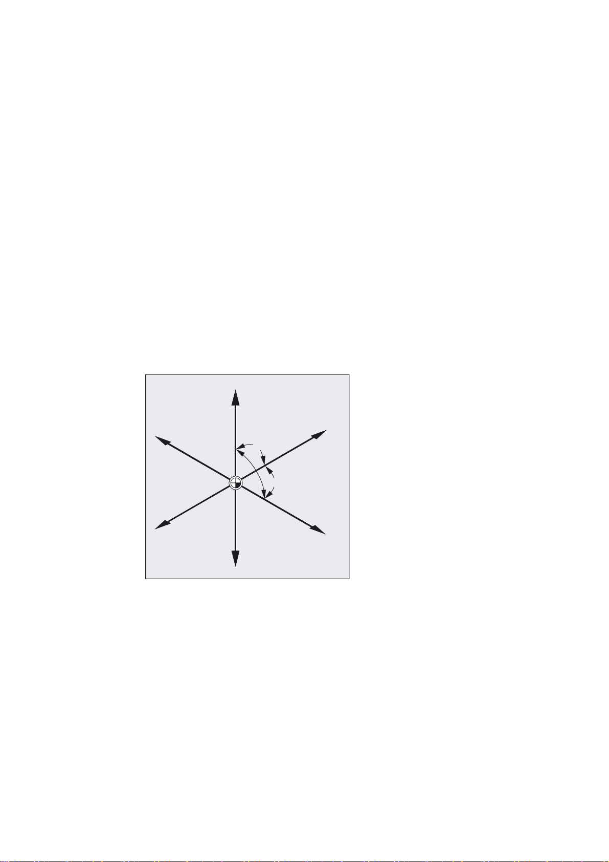
1.1.3 Polar coordinates
The method used to date to specify points in the coordinate system is known as the
"Cartesian coordinate" method.
However, there is another way to specify coordinates, i.e., as so-called "polar coordinates".
The polar coordinate method is useful only if a workpiece or part of a workpiece has radius
and angle measurements. The point, on which the measurements are based, is called the
"pole".
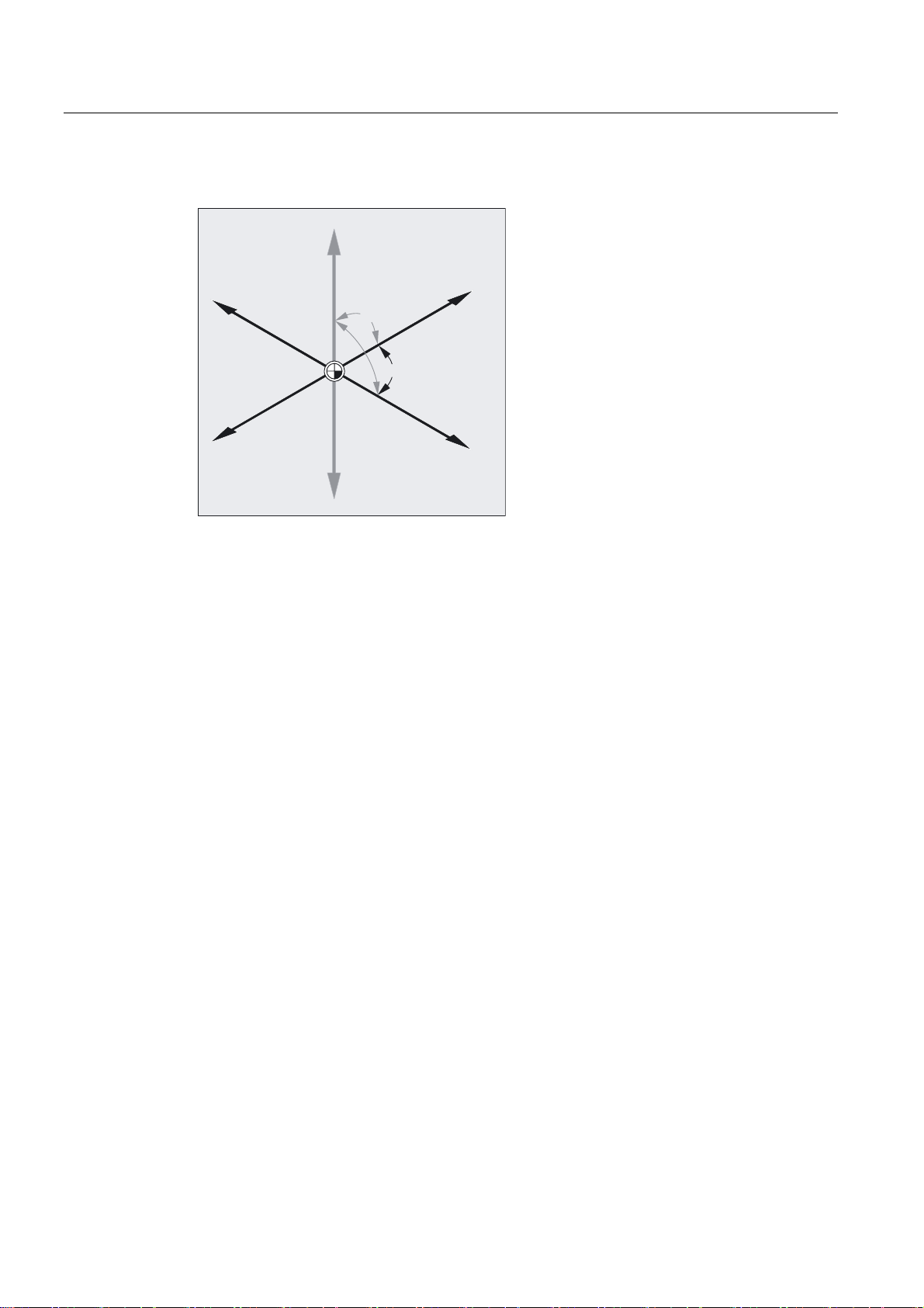
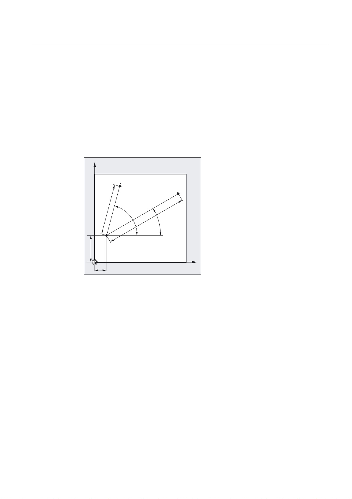
Example of polar data
The points P1 and P2 can then be described, with reference to the pole, as follows:
<
3
3
¡
¡
3ROH
P1 corresponds to radius =100 plus angle =30°
P2 corresponds to radius =60 plus angle =75°
1.1.4 Absolute dimensions
With absolute dimensions, all the positional data refer to the currently valid zero point.
Applied to tool movement this means:
the position, to which the tool is to travel.
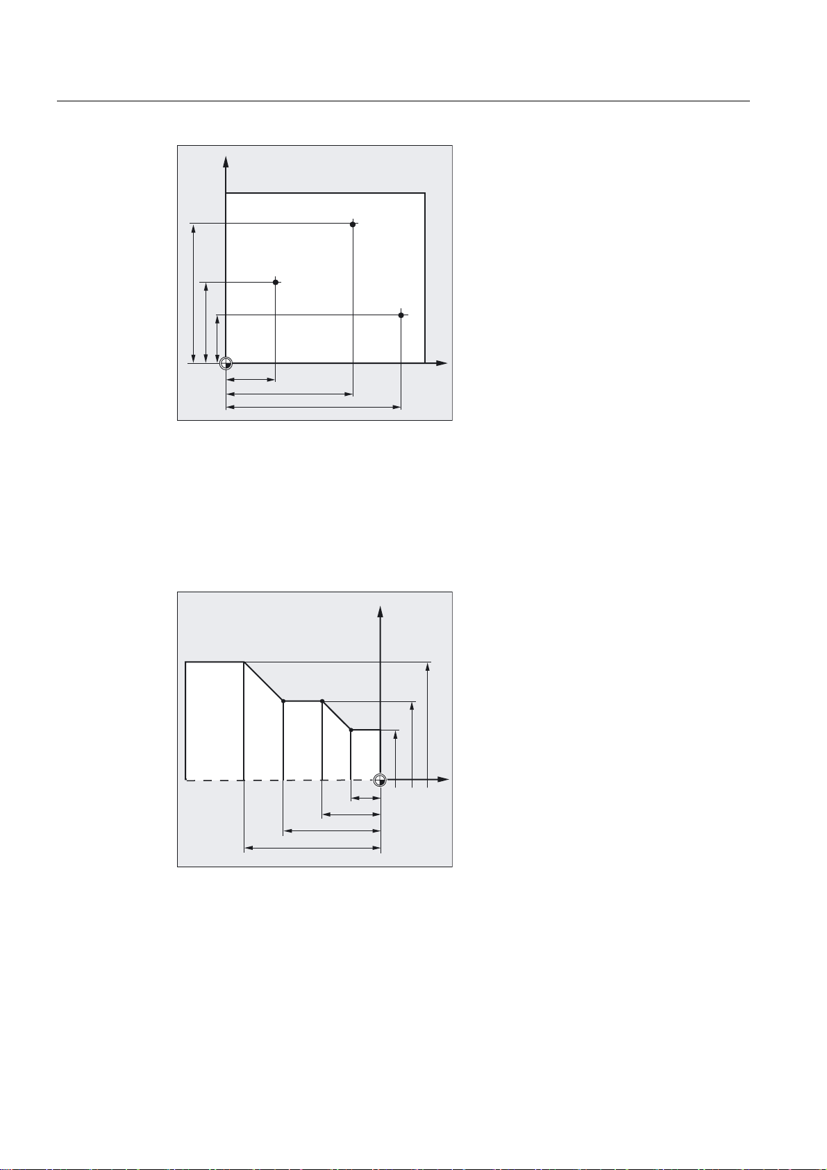
Example of milling
The positional parameters for points P1 to P3 in absolute dimensions referring to the zero
point are the following:
;
Fundamentals
Programming Manual, 10.2004 Edition, 6FC5 298-7AB00-0BP1
1-5
Fundamental Geometrical Principles
1.1 Description of workpiece points
<
3
3
3
;
P1 corresponds to X20 Y35
P2 corresponds to X50 Y60
P3 corresponds to X70 Y20
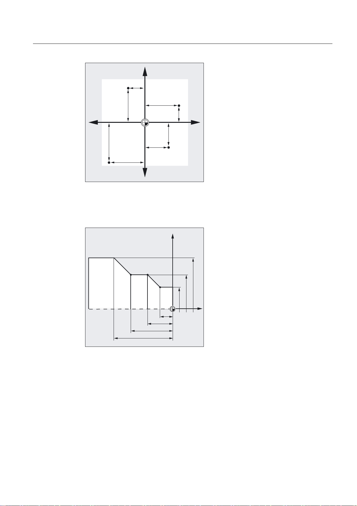
Example of turning
The positions for points P1 to P4 in absolute dimensions are as follows with reference to the
zero point:
P1 corresponds to X25 Z-7.5
P2 corresponds to X40 Z-15
P3 corresponds to X40 Z-25
3
3 3
3
;
=
P4 corresponds to X60 Z-35
Fundamentals
1-6 Programming Manual, 10.2004 Edition, 6FC5 298-7AB00-0BP1
Fundamental Geometrical Principles
1.1 Description of workpiece points
1.1.5 Incremental dimension
Production drawings are frequently encountered, however, where the dimensions refer not to
the origin, but to another point on the workpiece. In order to avoid having to convert such
dimensions, it is possible to specify them in incremental dimensions. Incremental dimensions
refer to the positional data for the previous point. Applied to tool movement this means:
The incremental dimensions describe the distance the tool is to travel.
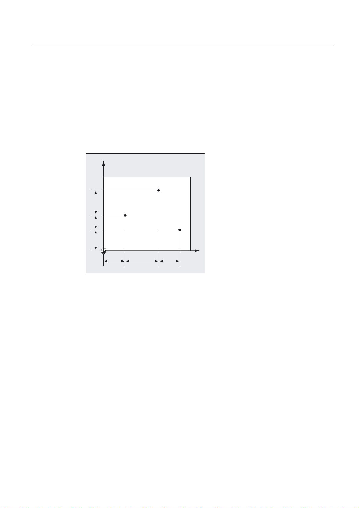
Example of milling
The positional data for points P1 to P3 in incremental dimensions are:
<
3
3
P1 corresponds to X20 Y35 ;(with reference to the zero point)
P2 corresponds to X30 Y20 ;(with reference to P1)
P3 corresponds to X20 Y-35 ;(with reference to P2)
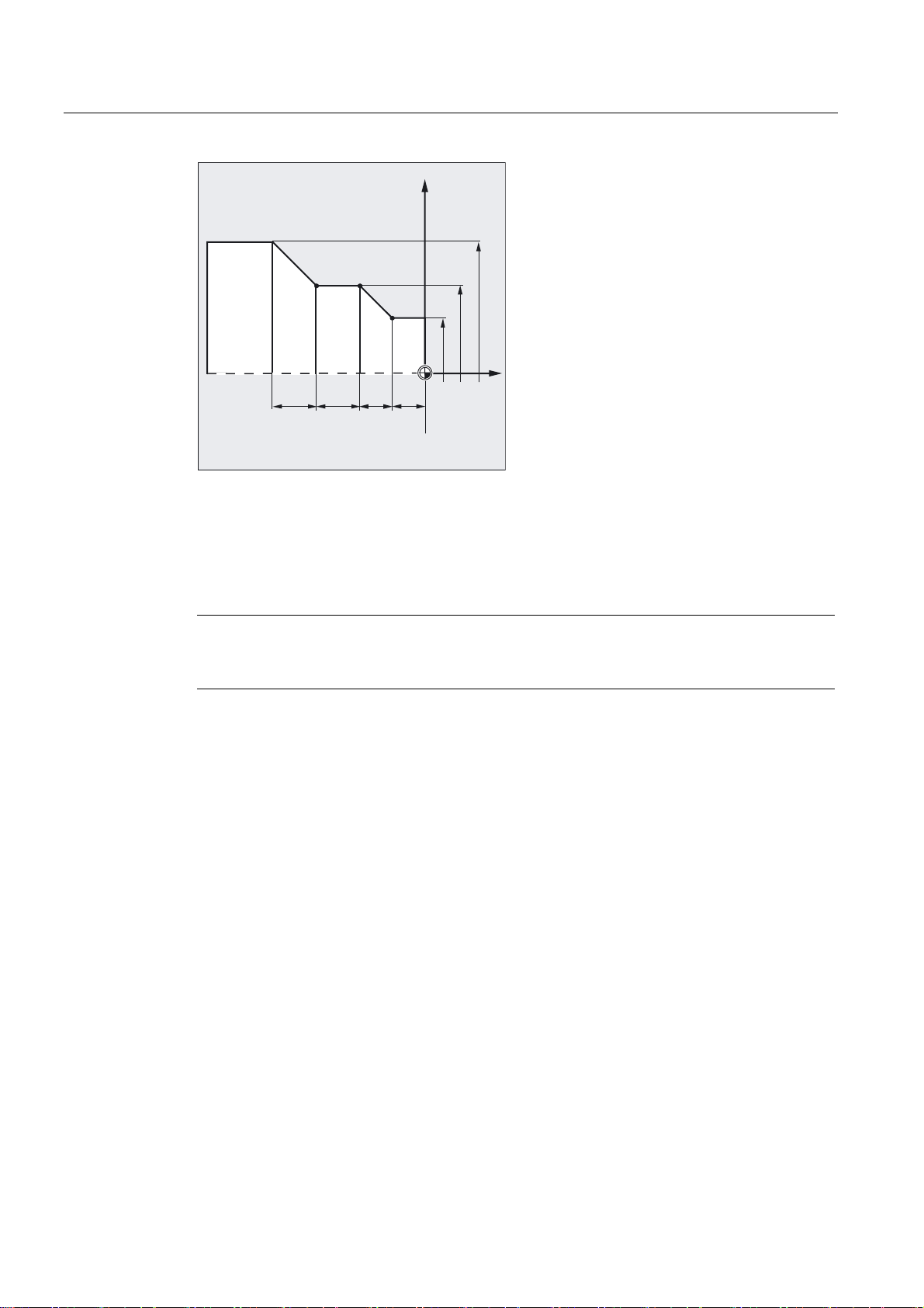
Example of turning
The positions for points P1 to P4 in incremental dimensions are as follows:
3
;
Fundamentals
Programming Manual, 10.2004 Edition, 6FC5 298-7AB00-0BP1
1-7
Fundamental Geometrical Principles
1.1 Description of workpiece points
;
3
3 3
3
=
G90 P1 corresponds to X25 Z-7.5 ;(with reference to the zero point)
G91 P2 corresponds to X15 Z-7.5 ;(with reference to P1)
G91 P3 corresponds to Z-10 ;(with reference to P2)
G91 P4 corresponds to X20 Z-10 ;(with reference to P3)
Note
When DIAMOF or DIAM90 is active, the path setpoint is programmed as a radius dimension
with G91.
1.1.6 Plane designations
When programming, it is necessary to specify the working plane so that the control system
can calculate the tool offset values correctly. The plane is also relevant to certain types of
circular programming and polar coordinates.
A plane is defined by means of two coordinate axes.
Fundamentals
1-8 Programming Manual, 10.2004 Edition, 6FC5 298-7AB00-0BP1
Fundamental Geometrical Principles
1.1 Description of workpiece points
Milling:
=
<
*
*
*
;
Turning:
Working planes
<
;
*
*
*
=
The third coordinate axis is perpendicular to this plane and determines the infeed direction of
the tool (e.g., for 2½ D machining).
The working planes are specified as follows in the NC program with G17, G18 and G19:
Plane
X/Y G17 Z
Z/X G18 Y
Y/Z G19 X
Designation
Infeed direction
Fundamentals
Programming Manual, 10.2004 Edition, 6FC5 298-7AB00-0BP1
1-9
Fundamental Geometrical Principles
1.2 Position of zero points
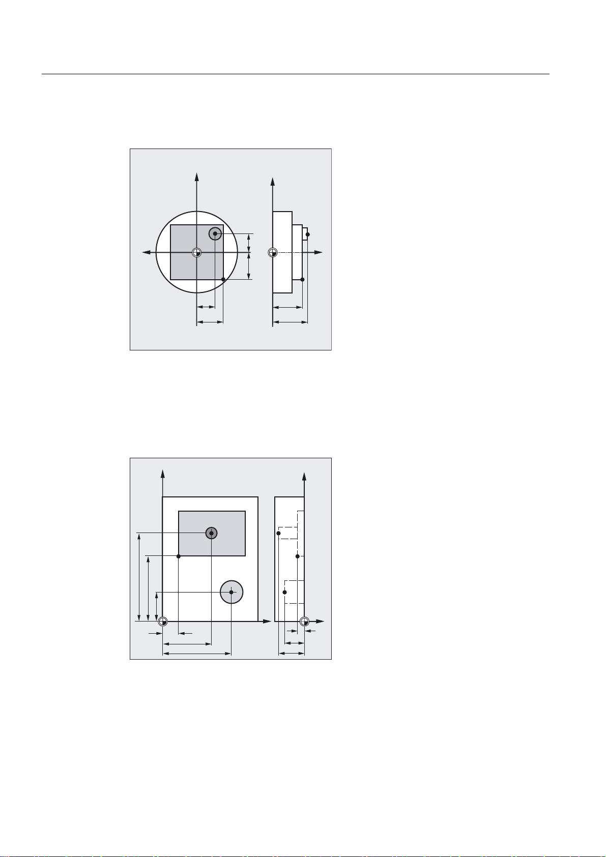
1.2 Position of zero points
The various origins (zero points) and reference positions are defined on the NC machine.
They are reference points
• for the machine to approach and
• for programming the workpiece dimensions.
The diagrams show the zero points and reference points for drilling/milling machines and
turning machines.
Milling:
<
Reference points
::
0
;
Turning:
;
5
%
0
$
:
=
They are:
M Machine zero
A Blocking point. Can coincide with the workpiece zero point (only turning
machines).
W Workpiece zero = Program zero
Fundamentals
1-10 Programming Manual, 10.2004 Edition, 6FC5 298-7AB00-0BP1

Fundamental Geometrical Principles
1.3 Position of coordinate systems
B
R Reference point. Position determined by cams and measuring system.
Start point. Can be defined for each program.
Start point of the first tool for machining.
The distance to the machine zero M must be known, so that the axis
position can be set at this place exactly on this value
1.3 Position of coordinate systems
1.3.1 Overview of various coordinate systems
We distinguish between the following coordinate systems:
• The machine coordinate system with the machine zero M
• The basic coordinate system (this can also be the workpiece coordinate system W)
• The workpiece coordinate system with the workpiece zero W
• The current workpiece coordinate system with the current offset workpiece zero Wa
In cases where different machine coordinate systems are in use (e.g., 5-axis transformation),
an internal transformation function mirrors the machine kinematics on the coordinate system
currently selected for programming.
Note
The individual axis identifiers are explained in the subsection headed "Axis types".
Fundamentals
Programming Manual, 10.2004 Edition, 6FC5 298-7AB00-0BP1
1-11
Fundamental Geometrical Principles
1.3 Position of coordinate systems
Milling coordinate system:
=
Z
P
=
<
P
0
;
P
=
D
<
Z
<
D
:
:D
;
D
;
Z
Turning coordinate system:
<
0
:
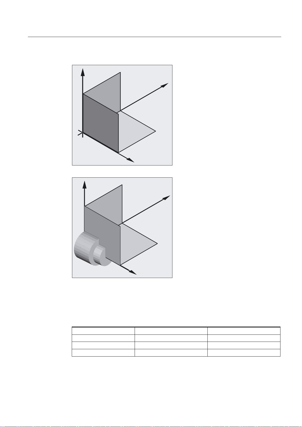
1.3.2 Machine coordinate system
The machine coordinate system comprises all the physically existing machine axes.
Reference points and tool and pallet changing points (fixed machine points) are defined in
the machine coordinate system.
;
=
Fundamentals
1-12 Programming Manual, 10.2004 Edition, 6FC5 298-7AB00-0BP1
Fundamental Geometrical Principles
1.3 Position of coordinate systems
Right-hand rule
=P
0
<P
;P
Where the machine coordinate system is used for programming (this is possible with some
of the G functions), the physical axes of the machine are addressed directly. No allowance
is made for workpiece clamping.
The orientation of the coordinate system relative to the machine depends on the machine
type. The axis directions follow the so-called "three-finger rule" of the right hand (in
accordance with DIN 66217).
Seen from in front of the machine, the middle finger of the right hand points in the opposite
direction to the infeed of the main spindle. Therefore:
• the thumb points in the +X direction
• the index finger points in the +Y direction
• the middle finger points in the +Z direction
Fundamentals
Programming Manual, 10.2004 Edition, 6FC5 298-7AB00-0BP1
1-13

Fundamental Geometrical Principles
1.3 Position of coordinate systems
=
<
;
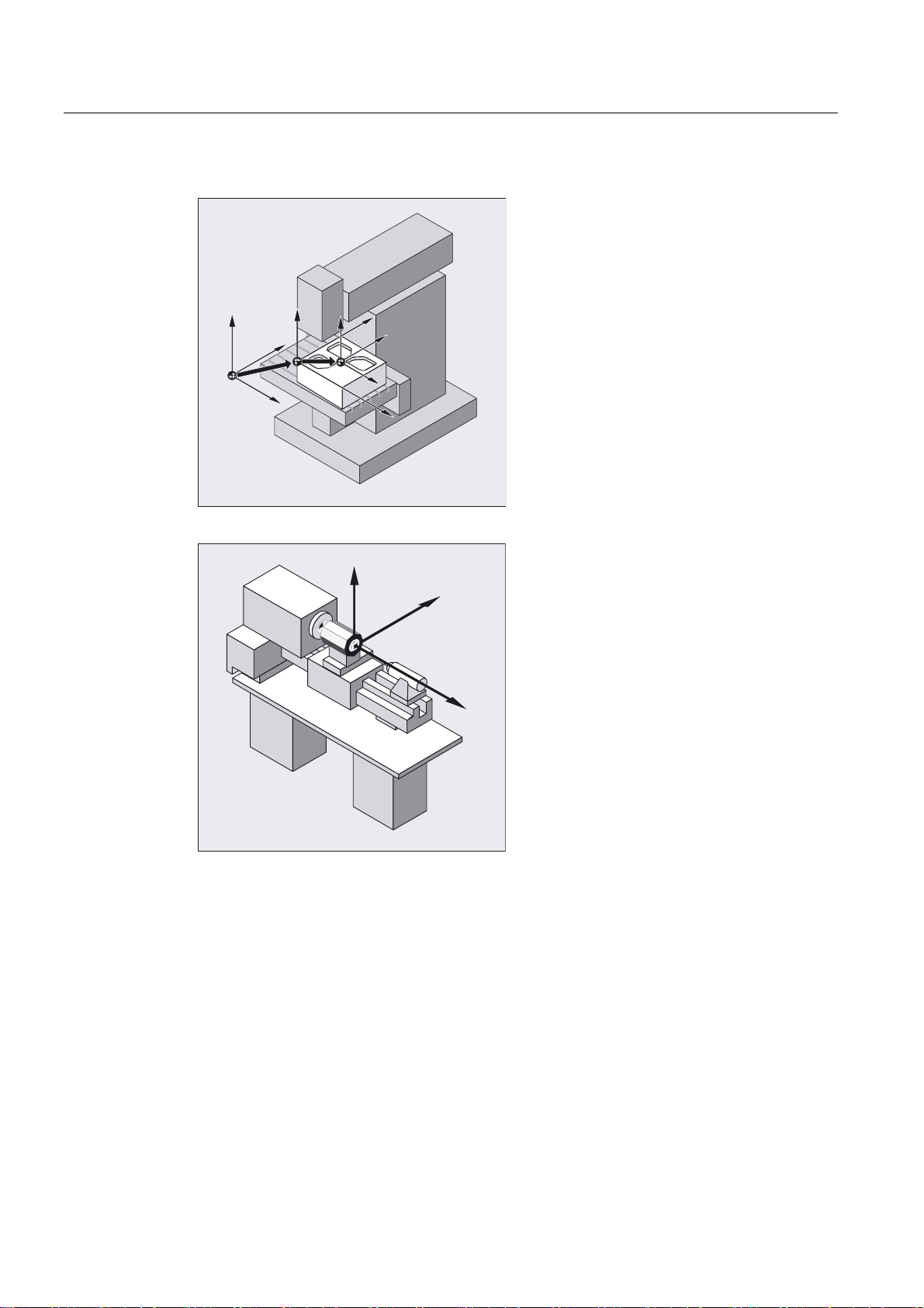
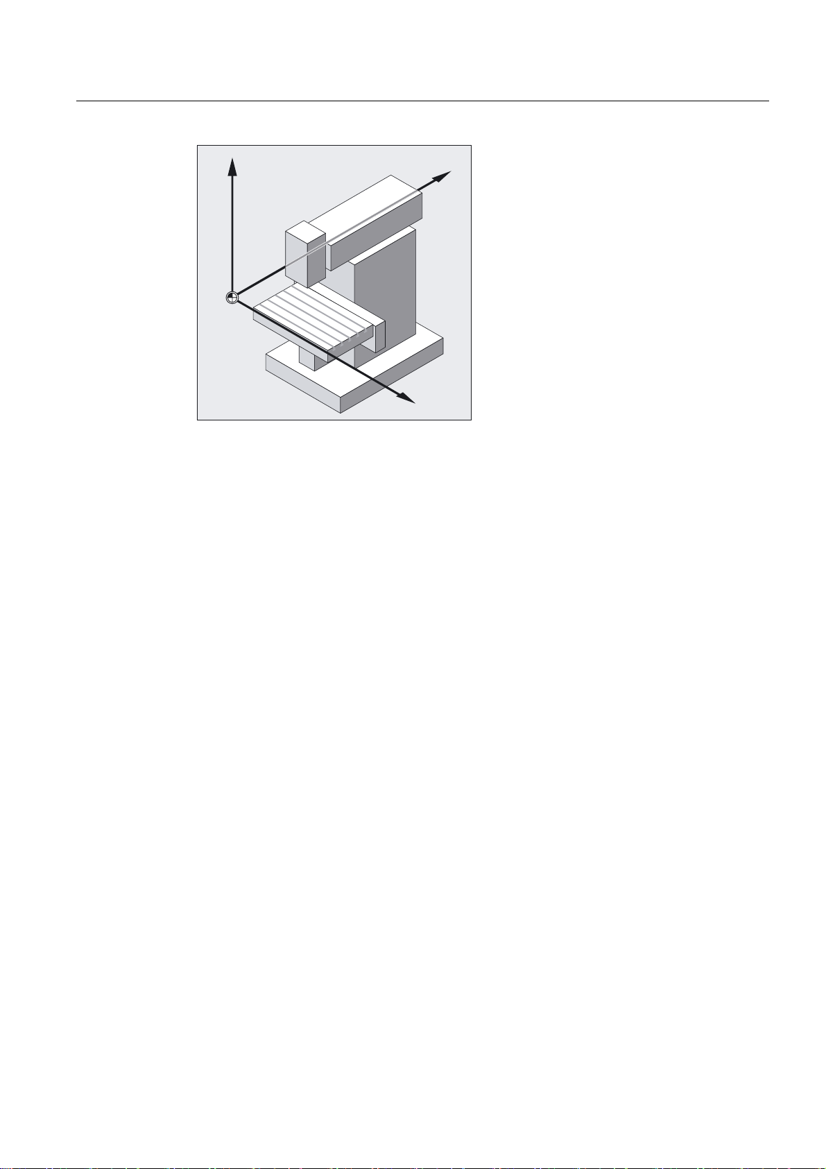
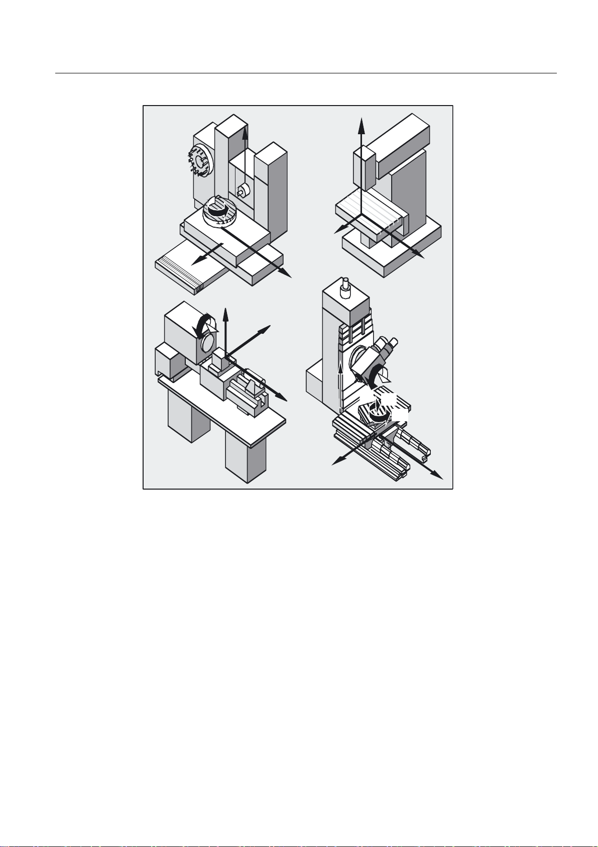
Determination from the right hand rule for different machine types
With different machine types the determination from the right hand rule can look different in
each case. The following are examples of machine coordinate systems for various
machines.
Fundamentals
1-14 Programming Manual, 10.2004 Edition, 6FC5 298-7AB00-0BP1
Fundamental Geometrical Principles
1.3 Position of coordinate systems
=
=
%
<
<
&
<
&
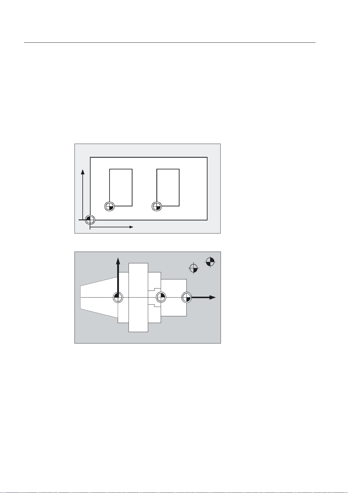
1.3.3 Basic coordinate system
;
=
;
=
;
%
;
%
$
$
<
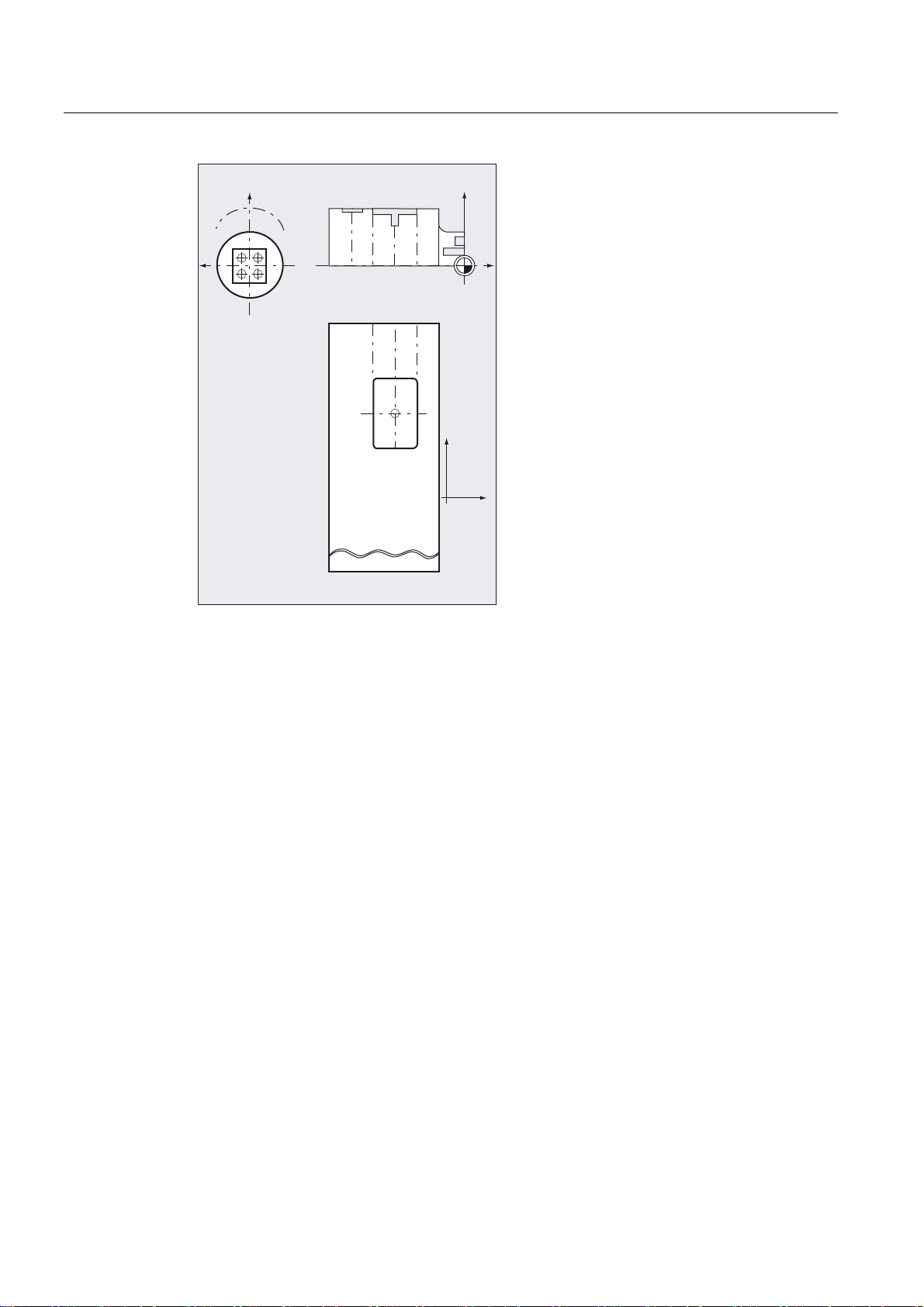
The basic coordinate system is a Cartesian coordinate system, which is mirrored by
kinematic transformation (for example, 5-axis transformation or by using Transmit with
peripheral surfaces) onto the machine coordinate system.
Fundamentals
Programming Manual, 10.2004 Edition, 6FC5 298-7AB00-0BP1
1-15
Fundamental Geometrical Principles
1.3 Position of coordinate systems
%DVLFFRRUGLQDWHV\VWHP
IRUIURQWIDFH
;
<
%DVLF
FRRUGLQDWHV\VWHP
IRUSHULSKHUDOVXUIDFH
:RUNSLHFH
FRRUGLQDWHV\VWHP
IRUSODQHRIURWDWLRQ
:
;
=
<
=
If there is no kinematic transformation, the basic coordinate system differs from the machine
coordinate system only in terms of the axis designations.
The activation of a transformation can produce deviations in the parallel orientation of the
axes. The coordinate system does not have to be at a right angle.
Fundamentals
1-16 Programming Manual, 10.2004 Edition, 6FC5 298-7AB00-0BP1
 Loading...