

Siemens SINUMERIK 840C, SIMODRIVE 611-D Installation Manual

SINUMERIK 840C
SIMODRIVE 611-D
Installation Guide 09.2001 Edition
Installation Lists
Service Documentation


SINUMERIK 840C
SIMODRIVE 611-D
Installation Lists
Installation Guide
Valid for:
Control SINUMERIK 840C/CE
Standard/Export Version
Software Version Software Version
1.x
2.x
3.x 1.x
4.x 2.x
5.x 3.x
6.x 4.x
09.2001 Edition
Drive SIMODRIVE 611-D

SINUMERIK® documentation
Printing history
Brief details of this edition and previous editions are listed below.
The status of each edition is shown by the code in the ”Remarks” column.
Status code in ”Remarks” column:
A . . . New documentation.
B . . . Unrevised reprint with new Order No.
C . . . Revised edition with new status.
If factual changes have been made on the page since the last edition, this is
indicated by a new edition coding in the header on that page.
Edition Order No. Remarks
11.92 6FC5197-0AA60-1BP0 A
06.93 6FC5197-2AA60-0BP0 C
12.93 6FC5197-3AA60-0BP0 C
10.94 6FC5197-4AA60-0BP0 C
03.95 6FC5197-4AA60-0BP1 C
09.95 6FC5197-5AA60-0BP0 C
04.96 6FC5197-5AA60-0BP1 C
08.96 6FC5197-5AA60-0BP2 C
07.97 6FC5197-6AA60-0BP0 C
01.99 6FC5197-6AA60-0BP1 C
09.01 6FC5197-6AA60-0BP2 C
This manual is included in the documentation on CD-ROM (DOCONCD)
Edition Order No. Remarks
10.01 6FC5198-6CA00-0BG2 C
Trademarks
SIMATIC®, SIMATIC HMI®, SIMATIC NET®, SIROTEC®, SINUMERIK® and SIMODRIVE® are trademarks of Siemens AG. All other product and system names are registered trademarks of their
respective companies and must be treated accordingly.
Other functions not described in this documentation might be
executable in the control. This does not, however, represent an
For more information, refer to the Internet:
http://www.ad.siemens.de/sinumerik
The publication was produced on the Siemens 5800 Office System.
The reproduction, transmission or use of this document or its
contents is not permitted without express written authority.
Offenders will be liable for damages. All rights, including created by
patent grant or registration of a utility model or design, are reserved,
© Siemens AG 1992-2001
All Rights Reserved
obligation to supply such functions with a new control or when
servicing.
We have checked that the contents of this publication agree with
the hardware and software described herein. The information given
in this publication is reviewed at regular intervals and any
corrections that might be necessary are made in the subsequent
printings. Suggestions for improvement are welcome at all times.
Subject to change without prior notice.
Order No. 6FC5197-6AA60-0BP2
Printed in the Federal Republic of Germany
Siemens-Aktiengesellschaft
Preliminary Remarks
aaaaaaaaaaaaaaaaaaaaaaaaaaaaaaaaaaaaaaaaaaaaaaaaaaa
a
a
a
a
a
a
a
a
a
a
a
a
a
a
a
a
a
aaaaaaaaaaaaaaaaaaaaaaaaaaaaaaaaaaaaaaaaaaaaaaaaaaa
a
aaaaaaaaaaaaaaaaaaaaaaaaaaaaaaaaaaaaaaaaaaaaaaaaaaa
a
aaaaaaaaaaaaaaaaaaaaaaaaaaaaaaaaaaaaaaaaaaaaaaaaaaa
a
aaaaaaaaaaaaaaaaaaaaaaaaaaaaaaaaaaaaaaaaaaaaaaaaaaa
a
aaaaaaaaaaaaaaaaaaaaaaaaaaaaaaaaaaaaaaaaaaaaaaaaaaa
a
aaaaaaaaaaaaaaaaaaaaaaaaaaaaaaaaaaaaaaaaaaaaaaaaaaa
a
aaaaaaaaaaaaaaaaaaaaaaaaaaaaaaaaaaaaaaaaaaaaaaaaaaa
a
aaaaaaaaaaaaaaaaaaaaaaaaaaaaaaaaaaaaaaaaaaaaaaaaaaa
a
aaaaaaaaaaaaaaaaaaaaaaaaaaaaaaaaaaaaaaaaaaaaaaaaaaa
a
aaaaaaaaaaaaaaaaaaaaaaaaaaaaaaaaaaaaaaaaaaaaaaaaaaaaaaaaaaaaaaaaaaaaaaaaaaaaaaaaaaaaaaaaaaaaaaaaaaaaaaaaaaaaaaa
a
a
a
a
a
a
a
a
a
a
a
a
a
a
a
a
a
a
a
a
a
a
a
a
a
a
a
a
a
a
a
a
a
a
a
a
a
a
a
a
a
a
a
a
a
a
a
aaaaaaaaaaaaaaaaaaaaaaaaaaaaaaaaaaaaaaaaaaaaaaaaaaaaaaaaaaaaaaaaaaaaaaaaaaaaaaaaaaaaaaaaaaaaaaaaa
a
a
a
a
a
a
a
a
a
a
a
a
a
a
a
a
a
a
a
a
a
a
a
a
a
a
a
a
a
a
a
a
a
a
a
a
a
a
a
a
a
aaaaaaaaaaaaaaaaaaaaaaaaaaaaaaaaaaaaaaaaaaaaaaaaa
aaaaaaaaaaaaaaaaaaaaaaaaaaaaaaaaaaaaaaaaaaaaaaaaa
aaaaaaaaaaaaaaaaaaaaaaaaaaaaaaaaaaaaaaaaaaaaaaaaa
aaaaaaaaaaaaaaaaaaaaaaaaaaaaaaaaaaaaaaaaaaaaaaaaa
aaaaaaaaaaaaaaaaaaaaaaaaaaaaaaaaaaaaaaaaaaaaaaaaa
aaaaaaaaaaaaaaaaaaaaaaaaaaaaaaaaaaaaaaaaaaaaaaaaa
aaaaaaaaaaaaaaaaaaaaaaaaaaaaaaaaaaaaaaaaaaaaaaaaa
aaaaaaaaaaaaaaaaaaaaaaaaaaaaaaaaaaaaaaaaaaaaaaaaa
Notes for the reader
a
a
a
a
a
a
a
a
This manual is intended for manufacturers of machine tools who use SINUMERIK 840C.
The "Installation Instructions" discuss the installation and start-up procedures, from installation
of the system through the testing of the most important functions.
The SINUMERIK 840C Installation Guide is divided into two separate manuals:
• 840C Installation Instructions
• 840C Installation Lists
The supplementary manual, which is entitled "SINUMERIK 840, Installation Lists", provides
additional aids in the form of lists and detailed information on NC and PLC machine data and
setting data, as well as lists of control and programmer alarms.
The manufacturer documentation for the SINUMERIK 840C control is divided into the
following parts:
• Interface
Part 1: Signals
Part 2: Connection Conditions
• Planning Guide PLC 135 WB/WB2/WD
• Function Macros
• Function Blocks
Package 0: Basic Functions
Package 1: Tool Management
Package 4/5:Computer Link
Package 7: Code Carrier
Package 8: PLC-controlled Data Input/Output
Additional SINUMERIK publications which are valid for all SINUMERIK controls may also be
consulted (e.g. Universal Interface, Measuring Cycles, CL800 Cycle Language).
Please contact your local SIEMENS office for further details.
Technical notes
A new Installation Guide is required for each new software version. Old Installation Guides can
be used only in part for new software versions.
aaaaaaaaaaaaaaaaaaaaaaaaaaaaaaaaaaaaaaaaaaaaaaaaaaaaaaaaaaaaaaaaaaaaaaaaaaaaaaaaaaaaaaaaaaaaaaaaaaaaaaaaaaaaa
aaaaaaaaaaaaaaaaaaaaaaaaaaaaaaaaaaaaaaaaaaaaaaaaaaaaaaaaaaaaaaaaaaaaaaaaaaaaaaaaaaaaaaaaaaaaaaaaaaaaaaaaaaaaa
aaaaaaaaaaaaaaaaaaaaaaaaaaaaaaaaaaaaaaaaaaaaaaaaaaaaaaaaaaaaaaaaaaaaaaaaaaaaaaaaaaaaaaaaaaaaaaaaaaaaaaaaaaaaa
aaaaaaaaaaaaaaaaaaaaaaaaaaaaaaaaaaaaaaaaaaaaaaaaaaaaaaaaaaaaaaaaaaaaaaaaaaaaaaaaaaaaaaaaaaaaaaa
aaaaaaaaaaaaaaaaaaaaaaaaaaaaaaaaaaaaaaaaaaaaaaaaaaaaaaaaaaaaaaaaaaaaaaaaaaaaaaaaaaaaaaaaaaaaaaaaaaaaaaaaaaaaa
aaaaaaaaaaaaaaaaaaaaaaaaaaaaaaaaaaaaaaaaaaaaaaaaaaaaaaaaaaaaaaaaaaaaaaaaaaaaaaaaaaaaaaaaaaaaaaa
aaaaaaaaaaaaaaaaaaaaaaaaaaaaaaaaaaaaaaaaaaaaaaaaaaaaaaaaaaaaaaaaaaaaaaaaaaaaaaaaaaaaaaaaaaaaaaaaaaaaaaaaaaaaa
aaaaaaaaaaaaaaaaaaaaaaaaaaaaaaaaaaaaaaaaaaaaaaaaaaaaaaaaaaaaaaaaaaaaaaaaaaaaaaaaaaaaaaaaaaaaaaa
As from software version 4, please refer to the Installation Lists manual
aaaaaaaaaaaaaaaaaaaaaaaaaaaaaaaaaaaaaaaaaaaaaaaaaaaaaaaaaaaaaaaaaaaaaaaaaaaaaaaaaaaaaaaaaaaaaaaaaaaaaaaaaaaaa
aaaaaaaaaaaaaaaaaaaaaaaaaaaaaaaaaaaaaaaaaaaaaaaaaaaaaaaaaaaaaaaaaaaaaaaaaaaaaaaaaaaaaaaaaaaaaaa
aaaaaaaaaaaaaaaaaaaaaaaaaaaaaaaaaaaaaaaaaaaaaaaaaaaaaaaaaaaaaaaaaaaaaaaaaaaaaaaaaaaaaaaaaaaaaaaaaaaaaaaaaaaaa
aaaaaaaaaaaaaaaaaaaaaaaaaaaaaaaaaaaaaaaaaaaaaaaaaaaaaaaaaaaaaaaaaaaaaaaaaaaaaaaaaaaaaaaaaaaaaaa
aaaaaaaaaaaaaaaaaaaaaaaaaaaaaaaaaaaaaaaaaaaaaaaaaaaaaaaaaaaaaaaaaaaaaaaaaaaaaaaaaaaaaaaaaaaaaaaaaaaaaaaaaaaaa
aaaaaaaaaaaaaaaaaaaaaaaaaaaaaaaaaaaaaaaaaaaaaaaaaaaaaaaaaaaaaaaaaaaaaaaaaaaaaaaaaaaaaaaaaaaaaaa
aaaaaaaaaaaaaaaaaaaaaaaaaaaaaaaaaaaaaaaaaaaaaaaaaaaaaaaaaaaaaaaaaaaaaaaaaaaaaaaaaaaaaaaaaaaaaaaaaaaaaaaaaaaaa
aaaaaaaaaaaaaaaaaaaaaaaaaaaaaaaaaaaaaaaaaaaaaaaaaaaaaaaaaaaaaaaaaaaaaaaaaaaaaaaaaaaaaaaaaaaaaaa
aaaaaaaaaaaaaaaaaaaaaaaaaaaaaaaaaaaaaaaaaaaaaaaaaaaaaaaaaaaaaaaaaaaaaaaaaaaaaaaaaaaaaaaaaaaaaaaaaaaaaaaaaaaaa
aaaaaaaaaaaaaaaaaaaaaaaaaaaaaaaaaaaaaaaaaaaaaaaaaaaaaaaaaaaaaaaaaaaaaaaaaaaaaaaaaaaaaaaaaaaaaaa
aaaaaaaaaaaaaaaaaaaaaaaaaaaaaaaaaaaaaaaaaaaaaaaaaaaaaaaaaaaaaaaaaaaaaaaaaaaaaaaaaaaaaaaaaaaaaaaaaaaaaaaaaaaaa
aaaaaaaaaaaaaaaaaaaaaaaaaaaaaaaaaaaaaaaaaaaaaaaaaaaaaaaaaaaaaaaaaaaaaaaaaaaaaaaaaaaaaaaaaaaaaaa
aaaaaaaaaaaaaaaaaaaaaaaaaaaaaaaaaaaaaaaaaaaaaaaaaaaaaaaaaaaaaaaaaaaaaaaaaaaaaaaaaaaaaaaaaaaaaaaaaaaaaaaaaaaaa
aaaaaaaaaaaaaaaaaaaaaaaaaaaaaaaaaaaaaaaaaaaaaaaaaaaaaaaaaaaaaaaaaaaaaaaaaaaaaaaaaaaaaaaaaaaaaaa
aaaaaaaaaaaaaaaaaaaaaaaaaaaaaaaaaaaaaaaaaaaaaaaaaaaaaaaaaaaaaaaaaaaaaaaaaaaaaaaaaaaaaaaaaaaaaaaaaaaaaaaaaaaaa
aaaaaaaaaaaaaaaaaaaaaaaaaaaaaaaaaaaaaaaaaaaaaaaaaaaaaaaaaaaaaaaaaaaaaaaaaaaaaaaaaaaaaaaaaaaaaaa
aaaaaaaaaaaaaaaaaaaaaaaaaaaaaaaaaaaaaaaaaaaaaaaaaaaaaaaaaaaaaaaaaaaaaaaaaaaaaaaaaaaaaaaaaaaaaaaaaaaaaaaaaaaaa
aaaaaaaaaaaaaaaaaaaaaaaaaaaaaaaaaaaaaaaaaaaaaaaaaaaaaaaaaaaaaaaaaaaaaaaaaaaaaaaaaaaaaaaaaaaaaaa
aaaaaaaaaaaaaaaaaaaaaaaaaaaaaaaaaaaaaaaaaaaaaaaaaaaaaaaaaaaaaaaaaaaaaaaaaaaaaaaaaaaaaaaaaaaaaaaaaaaaaaaaaaaaa
aaaaaaaaaaaaaaaaaaaaaaaaaaaaaaaaaaaaaaaaaaaaaaaaaaaaaaaaaaaaaaaaaaaaaaaaaaaaaaaaaaaaaaaaaaaaaaa
aaaaaaaaaaaaaaaaaaaaaaaaaaaaaaaaaaaaaaaaaaaaaaaaaaaaaaaaaaaaaaaaaaaaaaaaaaaaaaaaaaaaaaaaaaaaaaaaaaaaaaaaaaaaa
aaaaaaaaaaaaaaaaaaaaaaaaaaaaaaaaaaaaaaaaaaaaaaaaaaaaaaaaaaaaaaaaaaaaaaaaaaaaaaaaaaaaaaaaaaaaaaaaaaaaaaaaaaaaa
aaaaaaaaaaaaaaaaaaaaaaaaaaaaaaaaaaaaaaaaaaaaaaaaaaaaaaaaaaaaaaaaaaaaaaaaaaaaaaaaaaaaaaaaaaaaaaaaaaaaaaaaaaaaa
aaaaaaaaaaaaaaaaaaaaaaaaaaaaaaaaaaaaaaaaaaaaaaaaaaaaaaaaaaaaaaaaaaaaaaaaaaaaaaaaaaaaaaaaaaaaaaaaaaaaaaaaaaaaa
aaaaaaaaaaaaaaaaaaaaaaaaaaaaaaaaaaaaaaaaaaaaaaaaaaaaaaaaaaaaaaaaaaaaaaaaaaaaaaaaaaaaaaaaaaaaaaaaaaaaaaaaaaaaa
aaaaaaaaaaaaaaaaaaaaaaaaaaaaaaaaaaaaaaaaaaaaaaaaaaaaaaaaaaaaaaaaaaaaaaaaaaaaaaaaaaaaaaaaaaaaaaaaaaaaaaaaaaaaa
aaaaaaaaaaaaaaaaaaaaaaaaaaaaaaaaaaaaaaaaaaaaaaaaaaaaaaaaaaaaaaaaaaaaaaaaaaaaaaaaaaaaaaaaaaaaaaaaaaaaaaaaaaaaa
aaaaaaaaaaaaaaaaaaaaaaaaaaaaaaaaaaaaaaaaaaaaaaaaaaaaaaaaaaaaaaaaaaaaaaaaaaaaaaaaaaaaaaaaaaaaaaaaaaaaaaaaaaaaa
As from software version 3, the data relevant to SIMODRIVE 611-D
aaaaaaaaaaaaaaaaaaaaaaaaaaaaaaaaaaaaaaaaaaaaaaaaaaaaaaaaaaaaaaaaaaaaaaaaaaaaaaaaaaaaaaaaaaaaaaa
aaaaaaaaaaaaaaaaaaaaaaaaaaaaaaaaaaaaaaaaaaaaaaaaaaaaaaaaaaaaaaaaaaaaaaaaaaaaaaaaaaaaaaaaaaaaaaa
aaaaaaaaaaaaaaaaaaaaaaaaaaaaaaaaaaaaaaaaaaaaaaaaaaaaaaaaaaaaaaaaaaaaaaaaaaaaaaaaaaaaaaaaaaaaaaa
aaaaaaaaaaaaaaaaaaaaaaaaaaaaaaaaaaaaaaaaaaaaaaaaaaaaaaaaaaaaaaaaaaaaaaaaaaaaaaaaaaaaaaaaaaaaaaa
aaaaaaaaaaaaaaaaaaaaaaaaaaaaaaaaaaaaaaaaaaaaaaaaaaaaaaaaaaaaaaaaaaaaaaaaaaaaaaaaaaaaaaaaaaaaaaa
aaaaaaaaaaaaaaaaaaaaaaaaaaaaaaaaaaaaaaaaaaaaaaaaaaaaaaaaaaaaaaaaaaaaaaaaaaaaaaaaaaaaaaaaaaaaaaa
aaaaaaaaaaaaaaaaaaaaaaaaaaaaaaaaaaaaaaaaaaaaaaaaaaaaaaaaaaaaaaaaaaaaaaaaaaaaaaaaaaaaaaaaaaaaaaa
for a description of the alarms (Monitoring section).
This manual is valid for software versions 1, 2, 3, 4, 5 and 6.
is also provided.
a
a
a
a
a
a
a
a
a
a
a
a
a
a
a
a
a
a
a
a
a
a
a
a
a
a
a
a
a
a
a
a
a
a
a
a
a
a
a
a
a
a
a
aaaaaaaaaaaaaaaaaaaaaaaaaaaaaaaaaaaaaaaaaaaaaaaaaaa
a
a
aaaaaaaaaaaaaaaaaaaaaaaaaaaaaaaaaaaaaaaaaaaaaaaaa
a
a
a
a
a
a
a
a
a
a
a
a
a
a
a
aaaaaaaaaaaaaaaaaaaaa
aaaaaaaaaaaaaaaaaaaaa
aaaaaaaaaaaaaaaaaaaaa
aaaaaaaaaaaaaaaaaaaaa
aaaaaaaaaaaaaaaaaaaaa
aaaaaaaaaaaaaaaaaaaaa
aaaaaaaaaaaaaaaaaaaaa
aaaaaaaaaaaaaaaaaaaaa
aaaaaaaaaaaaaaaaaaaaa
aaaaaaaaaaaaaaaaaaaaa
aaaaaaaaaaaaaaaaaaaaa
aaaaaaaaaaaaaaaaaaaaa
aaaaaaaaaaaaaaaaaaaaa
aaaaaaaaaaaaaaaaaaaaa
aaaaaaaaaaaaaaaaaaaaa
aaaaaaaaaaaaaaaaaaaaa
aaaaaaaaaaaaaaaaaaaaa
aaaaaaaaaaaaaaaaaaaaa
aaaaaaaaaaaaaaaaaaaaa
aaaaaaaaaaaaaaaaaaaaa
aaaaaaaaaaaaaaaaaaaaa
aaaaaaaaaaaaaaaaaaaaa
aaaaaaaaaaaaaaaaaaaaa
aaaaaaaaaaaaaaaaaaaaa
aaaaaaaaaaaaaaaaaaaaa
aaaaaaaaaaaaaaaaaaaaa
aaaaaaaaaaaaaaaaaaaaa
aaaaaaaaaaaaaaaaaaaaa
aaaaaaaaaaaaaaaaaaaaa
aaaaaaaaaaaaaaaaaaaaa
aaaaaaaaaaaaaaaaaaaaa
aaaaaaaaaaaaaaaaaaaaa
aaaaaaaaaaaaaaaaaaaaa
aaaaaaaaaaaaaaaaaaaaa
aaaaaaaaaaaaaaaaaaaaa
aaaaaaaaaaaaaaaaaaaaa
aaaaaaaaaaaaaaaaaaaaa
aaaaaaaaaaaaaaaaaaaaa
aaaaaaaaaaaaaaaaaaaaa
aaaaaaaaaaaaaaaaaaaaa
aaaaaaaaaaaaaaaaaaaaa
aaaaaaaaaaaaaaaaaaaaa
aaaaaaaaaaaaaaaaaaaaa
aaaaaaaaaaaaaaaaaaaaa
aaaaaaaaaaaaaaaaaaaaa
aaaaaaaaaaaaaaaaaaaaa
aaaaaaaaaaaaaaaaaaaaa
aaaaaaaaaaaaaaaaaaaaa
aaaaaaaaaaaaaaaaaaaaa
aaaaaaaaaaaaaaaaaaaaa
aaaaaaaaaaaaaaaaaaaaa
aaaaaaaaaaaaaaaaaaaaa
aaaaaaaaaaaaaaaaaaaaa
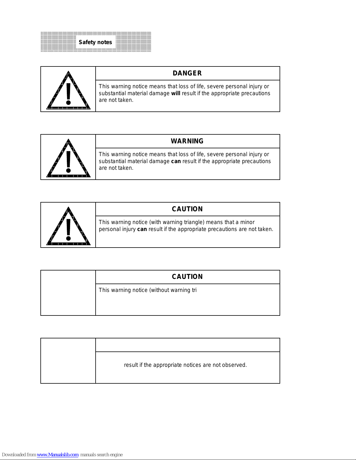
CAUTION
This warning notice (without warning triangle) means that a material
damage can result if the appropriate precautions are not taken.
aaaaaaaaaaaaaaaaaaaaaaaaaaaaaaaaaaaaaaaaaaaaaaaaa
aaaaaaaaaaaaaaaaaaaaaaaaaaaaaaaaaaaaaaaaaaaaaaaaa
aaaaaaaaaaaaaaaaaaaaaaaaaaaaaaaaaaaaaaaaaaaaaaaaa
aaaaaaaaaaaaaaaaaaaaaaaaaaaaaaaaaaaaaaaaaaaaaaaaa
aaaaaaaaaaaaaaaaaaaaaaaaaaaaaaaaaaaaaaaaaaaaaaaaa
aaaaaaaaaaaaaaaaaaaaaaaaaaaaaaaaaaaaaaaaaaaaaaaaa
aaaaaaaaaaaaaaaaaaaaaaaaaaaaaaaaaaaaaaaaaaaaaaaaa
Safety notes
This warning notice means that loss of life, severe personal injury or
substantial material damage will result if the appropriate precautions
are not taken.
This warning notice means that loss of life, severe personal injury or
substantial material damage can result if the appropriate precautions
are not taken.
a
a
a
a
a
a
a
a
DANGER
WARNING
CAUTION
This warning notice (with warning triangle) means that a minor
personal injury can result if the appropriate precautions are not taken.
NOTICE
This warning notice means that an undesired event or an undesired
state can result if the appropriate notices are not observed.

NC/Drive Machine Data 1
PLC Machine Data 2
Cycles Machine Data 3
NC Setting Data 4
PLC Interface 5
Startup, Flowcharts 6

Contents
Page
1 NC/Drive Machine Data . . . . . . . . . . . . . . . . . . . . . . . . . . . . . . . 1–1
1.1 General values . . . . . . . . . . . . . . . . . . . . . . . . . . . . . . . . . . . . . . . 1–2
1.2 Channel-specific values (max. 4 channels)
(as from SW 4: 6 channels) . . . . . . . . . . . . . . . . . . . . . . . . . . . . . . 1–9
1.3 Axis-specific values (max. 30 axes, 15 real and 15 fictitious) . . . . . . . 1–10
1.4 Spindle-specific values (max. 6 spindles) . . . . . . . . . . . . . . . . . . . . 1–13
1.5 General bits . . . . . . . . . . . . . . . . . . . . . . . . . . . . . . . . . . . . . . . . . 1–18
1.5.1 General bits, standard assignments . . . . . . . . . . . . . . . . . . . . . . . . 1–24
1.6 Spindle-specific bits (max. 6 spindles) . . . . . . . . . . . . . . . . . . . . . . 1–27
1.6.1 Spindle-specific bits, standard assignments . . . . . . . . . . . . . . . . . . . 1–28
1.7 Channel-specific bits (max. 4 channels)
(as from SW 4: 6 channels) . . . . . . . . . . . . . . . . . . . . . . . . . . . . . . 1–29
1.7.1 Channel-specific bits 1, standard assignments . . . . . . . . . . . . . . . . . 1–30
1.8 Axis-specific MD bits 1 (max. 30 axes) . . . . . . . . . . . . . . . . . . . . . . 1–31
1.8.1 Axis-specific MD bits 1, standard assignments . . . . . . . . . . . . . . . . 1–32
1.9 Compensation points for leadscrew error compensation . . . . . . . . . . 1–34
1.9.1 Channel-specific bits 2 . . . . . . . . . . . . . . . . . . . . . . . . . . . . . . . . . 1–35
1.9.2 Axis-specific MD 2 . . . . . . . . . . . . . . . . . . . . . . . . . . . . . . . . . . . . 1–36
1.9.3 Axis-specific MD bits 2 (max. 30 axes) . . . . . . . . . . . . . . . . . . . . . . 1–42
1.10 MD for display screen . . . . . . . . . . . . . . . . . . . . . . . . . . . . . . . . . . 1–43
1.10.1 Spindle-specific MD . . . . . . . . . . . . . . . . . . . . . . . . . . . . . . . . . . . 1–44
1.10.2 Axis-specific MD . . . . . . . . . . . . . . . . . . . . . . . . . . . . . . . . . . . . . . 1–47
1.10.3 MD bits for collision detection . . . . . . . . . . . . . . . . . . . . . . . . . . . . 1–49
1.10.4 MDs for flexible memory configuration . . . . . . . . . . . . . . . . . . . . . . 1–50
1.11 611A drive machine data . . . . . . . . . . . . . . . . . . . . . . . . . . . . . . . . 1–52
1.11.1 611A drive machine data MSD (SW 3) . . . . . . . . . . . . . . . . . . . . . . 1–52
1.11.2 611D drive machine data FDD (SW3) . . . . . . . . . . . . . . . . . . . . . . . 1–62
1.11.3 611D drive machine data FDD/MSD (as from SW 4) . . . . . . . . . . . . 1–66
1.11.4 FDD/MSD specific diagnostics/service MD (as from SW 4) . . . . . . . . 1–77
1.11.5 Servo service data (SSD) . . . . . . . . . . . . . . . . . . . . . . . . . . . . . . . 1–78
1.12 Safety Integrated (SI) machine data . . . . . . . . . . . . . . . . . . . . . . . . 1–79
1.12.1 SI NC machine data . . . . . . . . . . . . . . . . . . . . . . . . . . . . . . . . . . . 1–79
1.12.2 SI drive machine data . . . . . . . . . . . . . . . . . . . . . . . . . . . . . . . . . . 1–85
1.12.3 SI service data . . . . . . . . . . . . . . . . . . . . . . . . . . . . . . . . . . . . . . . 1–87
1.13 Coding of resolutions . . . . . . . . . . . . . . . . . . . . . . . . . . . . . . . . . . 1–88
1.14 Code table for axis name . . . . . . . . . . . . . . . . . . . . . . . . . . . . . . . 1–89
2 PLC Machine Data . . . . . . . . . . . . . . . . . . . . . . . . . . . . . . . . . . . 2–1
2.1 PLC machine data for operating system (DB 60) . . . . . . . . . . . . . . . 2–1
2.2 General PLC machine data for function blocks (DB 61) . . . . . . . . . . 2–5
2.3 User PLC machine data (DB 62) . . . . . . . . . . . . . . . . . . . . . . . . . . 2–6
2.4 General bits (DB 63) . . . . . . . . . . . . . . . . . . . . . . . . . . . . . . . . . . . 2–7
2.4.1 PLC MD bits standard assignment . . . . . . . . . . . . . . . . . . . . . . . . . 2–12
2.5 General PLC machine data bits for function blocks (DB 64) . . . . . . . 2–13
2.5.1 PLC machine data bits for user (DB 65) . . . . . . . . . . . . . . . . . . . . . 2–14
2.6 DBs set up for user . . . . . . . . . . . . . . . . . . . . . . . . . . . . . . . . . . . 2–14
2.6.1 Data words for user (DB 68) . . . . . . . . . . . . . . . . . . . . . . . . . . . . . 2–14
2.6.2 Data bits for user (DB 71) . . . . . . . . . . . . . . . . . . . . . . . . . . . . . . . 2–14

3 Cycles Machine Data . . . . . . . . . . . . . . . . . . . . . . . . . . . . . . . . . 3–1
4 NC Setting Data . . . . . . . . . . . . . . . . . . . . . . . . . . . . . . . . . . . . . 4–1
4.1 NC values . . . . . . . . . . . . . . . . . . . . . . . . . . . . . . . . . . . . . . . . . . 4–1
4.2 NC setting data bits . . . . . . . . . . . . . . . . . . . . . . . . . . . . . . . . . . . 4–2
5 PLC Interface . . . . . . . . . . . . . . . . . . . . . . . . . . . . . . . . . . . . . . . 5–1
5.1 Overview PLC interface . . . . . . . . . . . . . . . . . . . . . . . . . . . . . . . . . 5–1
5.1.1 Inputs, outputs, flags . . . . . . . . . . . . . . . . . . . . . . . . . . . . . . . . . . . 5–1
5.1.2 Data blocks (DB) . . . . . . . . . . . . . . . . . . . . . . . . . . . . . . . . . . . . . 5–2
5.1.3 Function blocks (FB, FX) . . . . . . . . . . . . . . . . . . . . . . . . . . . . . . . . 5–6
5.2 Basic signals . . . . . . . . . . . . . . . . . . . . . . . . . . . . . . . . . . . . . . . . 5–13
5.2.1 Assignment of DB 1 (diagnostics) . . . . . . . . . . . . . . . . . . . . . . . . . 5–15
5.2.2 Fast data channels (SW 4 and higher) . . . . . . . . . . . . . . . . . . . . . . 5–19
5.2.2.1 DB 2 configuring DB . . . . . . . . . . . . . . . . . . . . . . . . . . . . . . . . . . . 5–19
5.2.3 DB 3 data transfer areas . . . . . . . . . . . . . . . . . . . . . . . . . . . . . . . . 5–20
5.3 NCK/PLC interface . . . . . . . . . . . . . . . . . . . . . . . . . . . . . . . . . . . . 5–21
5.3.1 Channel-specific signals . . . . . . . . . . . . . . . . . . . . . . . . . . . . . . . . 5–21
5.3.1.1 Signals to NCK channel (DB 10 - DB 13) . . . . . . . . . . . . . . . . . . . . 5–21
5.3.1.2 Signals from NCK channel (DB 10 to DB 13) . . . . . . . . . . . . . . . . . 5–23
5.3.1.3 Auxiliary functions from NCK channel (DB 10 to DB 13) . . . . . . . . . 5–24
5.3.2 Axis-specific signals . . . . . . . . . . . . . . . . . . . . . . . . . . . . . . . . . . . 5–32
5.3.2.1 Axis-specific signals Safety Integrated (DB28) (SW 5 and higher) . . . 5–32
5.3.2.2 Axis-specific GI signals (DB 29) . . . . . . . . . . . . . . . . . . . . . . . . . . . 5–34
5.3.2.3 Axis-specific 611-D signals (DB 29) . . . . . . . . . . . . . . . . . . . . . . . . 5–35
5.3.3 M signals decoded according to list (DB 30) . . . . . . . . . . . . . . . . . . 5–36
5.3.4 Spindle-specific signals (DB31) . . . . . . . . . . . . . . . . . . . . . . . . . . . 5–37
5.3.4.1 Signals from spindle . . . . . . . . . . . . . . . . . . . . . . . . . . . . . . . . . . . 5–37
5.3.4.2 Spindle-specific GI signals . . . . . . . . . . . . . . . . . . . . . . . . . . . . . . . 5–37
5.3.4.3 Signals to spindle . . . . . . . . . . . . . . . . . . . . . . . . . . . . . . . . . . . . . 5–38
5.3.4.4 Spindle-specific GI signals to spindle . . . . . . . . . . . . . . . . . . . . . . . 5–38
5.3.4.5 Spindle-specific 611 D signals . . . . . . . . . . . . . . . . . . . . . . . . . . . . 5–39
5.3.5 Axis-specific signals (DB 32) . . . . . . . . . . . . . . . . . . . . . . . . . . . . . 5–40
5.3.6 Data transfer PLC/NC (DB 36) . . . . . . . . . . . . . . . . . . . . . . . . . . . . 5–42
5.3.7 Data transfer initiated using DB 37 . . . . . . . . . . . . . . . . . . . . . . . . . 5–43
5.3.8 Operator panel signals / PLC (DB 40) . . . . . . . . . . . . . . . . . . . . . . . 5–44
5.3.8.1 Key signals from operator panel (DB 40) . . . . . . . . . . . . . . . . . . . . . 5–44
5.3.8.2 Display dialog line (DB 40) . . . . . . . . . . . . . . . . . . . . . . . . . . . . . . 5–46
5.3.8.3 Menu selection (DB 40)* . . . . . . . . . . . . . . . . . . . . . . . . . . . . . . . . 5–47
5.3.8.4 Cursor data (DB 40) . . . . . . . . . . . . . . . . . . . . . . . . . . . . . . . . . . . 5–48
5.3.8.5 User key signals (DB 40) . . . . . . . . . . . . . . . . . . . . . . . . . . . . . . . 5–49
5.3.9 Interface command channel (DB 41) . . . . . . . . . . . . . . . . . . . . . . . 5–51
5.3.10 General interface NC/PLC (DB 48) . . . . . . . . . . . . . . . . . . . . . . . . . 5–53
5.3.11 PLC messages (DB 58) . . . . . . . . . . . . . . . . . . . . . . . . . . . . . . . . 5–55
5.3.11.1 Softkey function calls DB 59 . . . . . . . . . . . . . . . . . . . . . . . . . . . . . 5–60
5.3.12 DBs for PLC machine data (DB 60-65) . . . . . . . . . . . . . . . . . . . . . . 5–61
5.3.13 DBs set-up for user (DB 66, 67, 68, 71) . . . . . . . . . . . . . . . . . . . . . 5–61
5.3.14 Decoding lists for M signals (DB 80...DB 83) . . . . . . . . . . . . . . . . . . 5–62

6 Startup, Flowcharts . . . . . . . . . . . . . . . . . . . . . . . . . . . . . . . . . . 6–1
6.1 Restart after failure or replacement of the central service board . . . . 6–1
6.2 Saving the PLC program on the hard disk of the MMC . . . . . . . . . . . 6–3
6.3 Saving on/or loading from the hard disk (MMC) . . . . . . . . . . . . . . . . 6–4
6.4 Data transfer NC PC . . . . . . . . . . . . . . . . . . . . . . . . . . . . . . . . 6–5
6.5 Loading the archive file from an external PC to the NC . . . . . . . . . . 6–7

07.97 1 NC/Drive Machine Data
1 NC/Drive Machine Data
NC MD/Drive MD allocation
MD
1000
1599
2000
3999
4000
4999
5000
5199
5200
5399
5400
5599
5600
5999
6000
6999
9000
9299
11000
17969
18000
18599
20400
20449
2400*
3944*
6000*
62029
18000
4000*
4740*
to
999
to
to
to
to
to
to
to
to
to
to
to
to
to
to
to
to
Meaning
0
General MDs General data
Channel-specific MDs Channel data
Axis-specific MD 1 Axial data 1
Spindle-specific MD Spindle data
General MD bits General bits
Spindle-specific MD bits Bit displays
Channel-specific MD bits 1 Channel bits 1
Axis-specific MD bits 1 Axial bits 1
Leadscrew error,
compensation bits
Channel-specific MD bits 2 Channel bits 2
Axis-specific MD 2 Axial data 2
Axis-specific MD bits 2 Axial bits 2
MDs for multi-channel display Channel memory
set changeover, dynam. software
1
MDs for parameter
limit switch
Collision detection
MDs for flexible
memory configuration
Simodrive drive MD
(SW 3 and higher)
Safety Integrated MD
(SW 5.4 and higher)
(see Description of Functions
Softkey
Compensation flags
––––––
Various
axial data
––––––
Safety functions
Safety Integrated)
© Siemens AG 1992 All Rights Reserved 6FC5197- AA60
SINUMERIK 840C (IA)
1–1

1 NC/Drive Machine Data 09.95
1.1 General values
1.1 General values
MD
No.
D e s i g n a t i o n
Standard
value
Maximum
input value
Reference
system
Input
unit
1 Speed after prelimit switch 500 100000 IS 1000 units/min
2
3 Corner deceleration rate 500 100000 IS 1000 units/min
6 Threshold for point of intersect.
switch
1000 16000
2000
IS units
*)
7 Circle end point monitoring 5 32000 IS units
9 Error window on reapproach to
200 32000 IS units
circle contour
10 Feed after block search 1000 100000 IS 1000 units/min
13 Number of TO parameters 10 32 --
14 First password protected R
parameter
15 Last password protected R
parameter
16 First keyswitch protected R
parameter
0 999
1299
0 999
1299
0 999
1299
*)
*)
*)
--
--
--
17 Last keyswitch protected R
parameter
0 999
1299
*)
--
18 Zero offset group (L960) 1 10 --
20 Basic angle for nutating head 0 180000 IS 10
23 Number of buffer pairs
16 16 --
CP 231
24 Number of buffer pairs
16 16 -- --
CP 315 - 1
25 Number of buffer pairs
16 16 --
CP 315 - 2
26 User program useful data
234 254
*)
-- characters
length CP 231
27 User program useful data
234 254
*)
--
length CP 315 - 11 - 16
28 User program useful data
234 254
*)
--
length CP 315 - 2
_______
*) SW 4 and higher
-3
degrees
--
--
characters
characters
1–2
© Siemens AG 1992 All Rights Reserved 6FC5197- AA60
SINUMERIK 840C (IA)

09.95 1 NC/Drive Machine Data
1.1 General values
MD
No.
D e s i g n a t i o n
30 Number of sectors in pro-
Standard
value
Maximum
input value
Reference
system
10 1000 -- Sector
Input
cessing memory
100 Feedrate override
1 150 -- %
switch position 2
101 - // - 3 2 150 -- %
102 - // - 4 4 150 -- %
103 - // - 5 6 150 -- %
104 - // - 6 8 150 -- %
105 - // - 7 10 150 -- %
106 - // - 8 20 150 -- %
107 - // - 9 30 150 -- %
108 - // - 10 40 150 -- %
109 - // - 11 50 150 -- %
110 - // - 12 60 150 -- %
111 - // - 13 70 150 -- %
unit
112 - // - 14 75 150 -- %
113 - // - 15 80 150 -- %
114 - // - 16 85 150 -- %
115 - // - 17 90 150 -- %
116 - // - 18 95 150 -- %
117 - // - 19 100 150 -- %
118 - // - 20 105 150 -- %
119 - // - 21 110 150 -- %
120 - // - 22 115 150 -- %
121 - // - 23 120 150 -- %
122 - // - 24 0 150 -- %
123 - // - 25 0 150 -- %
124 - // - 26 0 150 -- %
125 - // - 27 0 150 -- %
126 - // - 28 0 150 -- %
127 - // - 29 0 150 -- %
128 - // - 30 0 150 -- %
© Siemens AG 1992 All Rights Reserved 6FC5197- AA60
SINUMERIK 840C (IA)
1–3

1 NC/Drive Machine Data 09.95
1.1 General values
MD
No.
D e s i g n a t i o n
Standard
value
Maximum
input value
Reference
system
Input
129 - // - 31 0 150 -- %
130 - // - 32 0 150 -- %
131 Spindle override
50 150 -- %
switch position 1
132 - // - 2 55 150 -- %
133 - // - 3 60 150 -- %
134 - // - 4 65 150 -- %
135 - // - 5 70 150 -- %
136 - // - 6 75 150 -- %
137 - // - 7 80 150 -- %
138 - // - 8 85 150 -- %
139 - // - 9 90 150 -- %
140 - // - 10 95 150 -- %
141 - // - 11 100 150 -- %
unit
142 - // - 12 105 150 -- %
143 - // - 13 110 150 -- %
144 - // - 14 115 150 -- %
145 - // - 15 120 150 -- %
146 - // - 16 120 150 -- %
147 Rapid override
1 100 -- %
switch position 1
148 - // - 2 10 100 -- %
149 - // - 3 50 100 -- %
150 - // - 4 100 100 -- %
151 - // - 5 0 100 -- %
152 - // - 6 0 100 -- %
153 - // - 7 0 100 -- %
154 - // - 8 0 100 -- %
155 Position controller basic cycle 4 40 --
Multiple of the
drive’s basic
cycle
156 Switch-off delay
Controller enable
1–4
200 1000 -- ms
© Siemens AG 1992 All Rights Reserved 6FC5197- AA60
SINUMERIK 840C (IA)

09.01 1 NC/Drive Machine Data
1.1 General values
MD
No.
D e s i g n a t i o n
157 Control type for
standard cycles
Standard
value
T 61..
M 62..
Maximum
input value
--
--
Reference
system
-- --
Input
160 Interpolation cycle 4 32 -- --
161 Number of IKA configurations via
032----
PLC/DB 48
164 Deadtime for calculation for
extended thread
28
36
4)
48 --
1
/8 of IPO clock
frequency
168 Basic cycle time for drive 16 32 -- 62.5 µs
200 Reserved
208 Maximum tool wear P5, P6 999 999 999 999
99 999 999
209 Maximum tool wear P7 999 999 999 999
99 999 999
3)
3)
-- 0.01 units
0.00001
-- 0.01 units
0.00001
210 Number of TO areas 1 4 -- --
211 Start D No. for TO area 1 1 809 -- --
212 ” ” 2 0 809 -- --
213 ” ” 3 0 809 -- --
214 ” ” 4 0 809 -- --
228 User menu for MDA 0 1000 -- --
229 User menu for JOG 0 1000 -- --
230 User menu for TEACH IN 0 1000 -- --
231 User menu for AUTOMATIC 0 1000 -- --
232 User menu for JOG/REFPOINT 0 1000 -- --
250 Change of language
260 M function ”C axis ON”
261 M function ”C axis OFF”
300 Tool allowance for protection
1)
0 1 -- --
-
1 9999 -- --
-
1 9999 -- -0 9999 9999 IS --
zone adjustment
310
Output byte to user interface 0 94
2)
Output byte to mixed I/O 0 22
311
2)
312 Assignment of outputs
module
2)
for emergency
022
999
999
3)
3)
2)
2
-- --
-- --
-- --
retraction 1st mode grp
313:Assignment of outputs
module
2)
for emergency
022----
retraction 2nd mode grp
317 Assignment of outputs
module
2)
for emergency
022
2)
2
-- --
retraction 6th mode grp
MDs 314 to 317 (as from SW 4)
_______
1)
Up to SW 1
2)
SW 3 and higher
3)
SW 4 and higher
4)
SW 5 and higher
unit
© Siemens AG 1992 All Rights Reserved 6FC5197- AA60
SINUMERIK 840C (IA)
1–5

1 NC/Drive Machine Data 01.99
1.1 General values
MD
No.
318
323
D e s i g n a t i o n
Assignment of inputs of Mixed
I/O module for retraction of one
:
mode group 1st mode group
6th mode group
324 Time for interpolator-controlled
continuation
325 Maximum time for interpolator-
controlled deceleration
330 Deadtime compensation for
dwell axis actual value
331 Sine of angular range for
tangential transitions TRC
332 Deadtime compensation dwell
axis setpoint
333 Deadtime compensation dwell
spindle actual value
334 Deadtime compensation dwell
spindle setpoint
335 Min. reduction factor
(velocity limitation FA warning
threshold)
336 Velocity increase factor
(velocity linitation FA warning
threshold)
337 2nd MCS displacement in X
coordinates
338 2nd MCS displacement in Y
coordinates
339 2nd MCS displacement in Z
coordinates
340 3rd MCS displacement in X
coordinates
341 3rd MCS displacement in Y
coordinates
342 3rd MCS displacement in Z
coordinates
343 4th MCS displacement in X
coordinates
344 4th MCS displacement in Y
coordinates
345 4th MCS displacement in Z
coordinates
_______
1) As fromSW 4
2) As from SW 5
3) As from SW 6
:
1)
1)
1)
2)
2)
2)
3)
3)
3)
3)
3)
3)
3)
3)
3)
3)
3)
1)
ˆ=approx.
0.0005 deg.
Standard
value
081
0 1 000
0 1 000
Maximum
input value
1)
8
16 000
16 000
1)
1)
Reference
system
-- --
-- ms
-- ms
550 16 000 -- % of IPO
2
16 000
ˆ=approx.
4.5 degrees
-- 0.5 * 10
450 16 000 -- % of IPO
550 16 000 -- % of IPO
450 16 000 -- % of IPO
100 100 -- %
0 1000 -- 0.01 %
0 9999 9999 IS units
550 16 000 IS units
550 16 000 IS units
550 16 000 IS units
550 16 000 IS units
550 16 000 IS units
550 16 000 IS units
550 16 000 IS units
550 16 000 IS units
Input
unit
cycle
cycle
cycle
cycle
-5
1–6
© Siemens AG 1992 All Rights Reserved 6FC5197- AA60
SINUMERIK 840C (IA)

01.99 1 NC/Drive Machine Data
1.1 General values
MD
No.
D e s i g n a t i o n
Standard
value
Maximum
input value
Reference
system
Input
unit
730 Delta X offset 0 ±99999999 IS units
731 Delta Y offset 0 ±99999999 IS units
732 Delta Z offset 0 ±99999999 IS units
733 Angle of rotation X 0 ±99999999 IS 10
734 Angle of rotation Y 0 ±99999999 IS 10
735 Angle of rotation Z 0 ±99999999 IS 10
-5
-5
-5
736 Parameter 7 0 ±99999999 IS units
737 Parameter 8 0 ±99999999 IS units
738 Minimum speed for TRANSMIT 10 ±99999999 IS units/IPO cycle
739 Axis with constant cutting
speed
0 30 Number of the
axis for G96
740 2nd transformation, param. 1 0 ±99999999 IS units
. - // -- // -- // -- // -- // -
750 3rd transformation, param. 1 0 ±99999999 IS units
. - // -- // -- // -- // -- // -
760 4th transformation, param. 1 0 ±99999999 IS units
. - // -- // -- // -- // -- // -
770 5th transformation, param. 1 0 ±99999999 IS units
. - // -- // -- // -- // -- // -
780 6th transformation, param. 1 0 ±99999999 IS units
. - // -- // -- // -- // -- // -
790 7th transformation, param. 1 0 ±99999999 IS units
. - // -- // -- // -- // -- // -
800 8th transformation, param. 1 0 ±99999999 IS units
. - // -- // -- // -- // -- // -
© Siemens AG 1992 All Rights Reserved 6FC5197- AA60
SINUMERIK 840C (IA)
1–7

1 NC/Drive Machine Data 09.95
1.1 General values
MD
No.
876 Leading axis No. 1 0 9 ---
877 Following axis No. 1 0 9 ---
878 Leading axis No. 2 0 9 ---
879 Following axis No. 2 0 9 ---
880 Leading axis No. 3 0 9
881 Following axis No. 3 0 9
882 Leading axis No. 4 0 9
883 Following axis No. 4 0 9
884 Leading axis No. 5 0 9
885 Following axis No. 5 0 9
886 Leading axis No. 6 0 9
887 Following axis No. 6 0 9
888 Leading axis No. 7 0 9
889 Following axis No. 7 0 9
D e s i g n a t i o n
Standard
value
Maximum
input value
Reference
system
--- ---
--- ---
--- ---
--- ---
--- ---
--- ---
--- ---
--- ---
--- ---
--- ---
Input
unit
---
---
---
---
890 Leading axis No. 8 0 9
891 Following axis No. 8 0 9
892 Leading axis No. 9 0 9
893 Following axis No. 9 0 9
894 Leading axis No. 10 0 9
895 Following axis No. 10 0 9
896 Leading axis No. 11 0 9
897 Following axis No. 11 0 9
898 Leading axis No. 12 0 9
899 Following axis No. 12 0 9
900
901
902
903
904
--- ---
--- ---
--- ---
--- ---
--- ---
--- ---
--- ---
--- ---
--- ---
--- ---
1–8
© Siemens AG 1992 All Rights Reserved 6FC5197- AA60
SINUMERIK 840C (IA)

01.99 1 NC/Drive Machine Data
1.2 Channel-specific values (max. 4 channels) (as from SW 4: 6 channels)
1.2 Channel-specific values (max. 4 channels)
(as from SW 4: 6 channels)
MD
No.
D e s i g n a t i o n
100* Mode group 1 2
Standard
value
Maximum
input value
6
4)
Reference
system
-- --
102* Reserved
104* TO area for channel 1 4
6
106* No. of enabled program 0
4)
1)
-- --
-- --
108* Initial setting 1st G group 1 35 --
110* Initial setting 3rd G group M:17
19 -- --
T:18
112* Initial setting 6th G group 54 57 -- --
114* Initial setting 8th G group M:60
64 -- --
T:64
116* Initial setting 9th G group
118* Initial setting 12th G group M:94
0 0 -- --
97 -- --
T:95
120* Initial setting 15th G group 150 159 -- --
122* Initial setting 25th G group
3)
130* Device type for execution from
450 451 -- --
0 0. 5 -- --
external
132* Device number for execution
0 0 -- --
from external
134* Cycle number on
program start
136* Cycle number on
program end
140* Initial setting of
6th G group
142* Initial setting of tool offset
block
146* Corner deceleration speed
G620/G00
148* Corner deceleration
G62 w/o G36
150* Corner deceleration G62 with
G36
_______
1) % +9999
L - 9999
all %, L = 0
2) SW 3 and higher
3) SW 2 and higher
4) SW 4 and higher
4)
4)
2)
2)
4)
4)
4)
0 9 999 -- --
0 9 999 -- --
54 57 -- --
0 819 -- --
0 100 000 IS 1000 units/min
0 100 000 IS 1000 units/min
0 100 000 IS 1000 units/min
Input
unit
© Siemens AG 1992 All Rights Reserved 6FC5197- AA60 1–9
SINUMERIK 840C (IA)

1 NC/Drive Machine Data 01.99
1.3 Axis-specific values (max. 30 axes, 15 real and 15 fictitious)
1.3 Axis-specific values (max. 30 axes, 15 real and 15 fictitious)*
MD
No.
D e s i g n a t i o n
200* 1st measuring system
connection
2000
Setpoint on digital drive 0 --
2)
1)
6)
Standard
value
0
0
0
Maximum
input value
05 03 00 00
15 02 10 15
30 02 10 30
Reference
system
Analog
Digital
Digital
2-3
2000
SPC/HMS setpoint output 0
4-5
2000
Drive/servo loop module No. 0
6-7
204* Exact stop limit coarse 40
208* Exact stop limit fine 10
212* Zero speed control 100
16000
99 999 999
16000
99 999 999
16000
99 999 999
5)
5)
5)
MS units
MS units
MS units
216* Reserved
220* Backlash compensation
0 +/- 16000 MS units
1st measuring system
224* 1st software limit switch plus 99 999999 +/- 99999999 MS units
228* 1st software limit switch minus - 99999999 +/- 99999999 MS units
232* 2nd software limit switch plus +99999999 +/- 99999999 MS units
236* 2nd software limit switch minus - 99999999 +/- 99999999 MS units
240* Reference point value 0 +/- 99999999 MS units
244* Reference point offset 0 +/- 99999999 MS units
252* Servo gain factor 1666 10000
6)
80 000
256* Scaling max. velocity 10000 99999999 --
0.01 s
mm/min,
inch/min,
deg/min
260* Scaling max. setpoint speed
8000 99999999 mV
2)
5)
264* Threshold for drive error
Max. set speed
268*
(IPO-STOP)
272* Drift compensation
1)
2)
1)
2)
5)
1)
2)
276* Acceleration 50
_______
1) Up to SW 2
2) SW 3 and higher
4) SW 4 and higher
5) SW 4.4 and higher
6) SW 5 and higher
*) SW 5: 30 real axes
10000
9000
9600
12000
20000
20000
15000
20000
8192
20000
20000
0
+/- 500 --
0
2)
16000
9999 9999
9900 0000
4)
5)
0.01 % of max.
setpoint
--
VELO
0.01 % of max.
motor speed
--
VELO
0.01 % of max.
motor speed
VELO
0.01 % of max.
motor speed
IS 10000 units/s
Input
unit
--
-1
2
1–10 © Siemens AG 1992 All Rights Reserved 6FC5197- AA60
SINUMERIK 840C (IA)

09.95 1 NC/Drive Machine Data
1.3 Axis-specific values (max. 30 axes, 15 real and 15 fictitious)
MD
No.
D e s i g n a t i o n
Standard
value
Maximum
input value
Reference
system
Input
unit
280* Max. speed at G00 10000 99999999 IS 1000 units/min
284* Ref. point creep velocity 300 99999999 IS 1000 units/min
288* Jog velocity 2000 99999999 IS 1000 units/min
292* Jog rapid 5000 99999999 IS 1000 units/min
296* Ref. point approach velocity 10000 99999999 IS 1000 units/min
300* Incremental velocity 500 99999999 IS 1000 units/min
304* Interpolation parameter name
T:
M:
1, 2, 3
3040 = 1
3041 = 3
3042 = 0
3640 = 1
3041 = 2
3042 = 3
3
308* Cut-off frequency C encoder 200 16000 kHz
312* Feedforward factor 0 1000 0.1%
316* Reference pointer
0 249 -- MD offset
compensation plus
320* Reference pointer
compensation minus
324* Distance between 2 leadscrew
error compensation values
328* Compensation value with
leadscrew error compensation
0 249 -- MD offset
0 32000 MS units
0 100 MS units
© Siemens AG 1992 All Rights Reserved 6FC5197- AA60 1–11
SINUMERIK 840C (IA)

1 NC/Drive Machine Data 01.99
1.3 Axis-specific values (max. 30 axes, 15 real and 15 fictitious)
MD
No.
D e s i g n a t i o n
332* Tolerance band contour
Standard
value
1000 99999999 MS units
Maximum
input value
Reference
system
Input
unit
monitoring
336* Threshold velocity contour 5 1000000 IS 1000 units/min
344* Module value rotary axis for
360000 + 92160000 MS units
leadscrew error compensation
356* IKA warning unit
1)
±99999999 MS units
360* Mode group 1 2
3)
6
364* u: Pulses var. increment
weighting
368* v: Traversing path var.
increment weighting
1 16000
99999999
2 16000
99999999
2)
-- --
MS --
2)
372* Delay zero speed control 200 1000 ms
376* Acceleration with controlled
0 99 999 999 IS 10 000 units/s
emergency retraction
(G425) (SW 6 and higher)
2
384* Setpoint output
3840
Setpoint on digital drive
2-3
3840
SPC/HMS setpoint output
1)
4)
3)
3)
0
0
0
0 12
05120000
15001000
30001000
ANALOG
DIGITAL
DIGITAL
4-5
3840
Drive/servo loop
6-7
module No.
388* Weighting factor for path
3)
0 30
0 99999999 -- --
conversion
392* Time constant symmetrizing
0 1000 0.1 ms
filter
396* Absolute offset 0 99999999 MS units
_______
1) SW 3 and higher
2) SW 2 and higher
3) SW 4 and higher
4) SW 5 and higher
--
1–12 © Siemens AG 1992 All Rights Reserved 6FC5197- AA60
SINUMERIK 840C (IA)

08.96 1 NC/Drive Machine Data
1.4 Spindle-specific values (max. 6 spindles)
1.4 Spindle-specific values (max. 6 spindles)
MD
No.
D e s i g n a t i o n
400* Assignment spindle 0
4000
Setpoint on digital drive 0
Standard
value
05 03 00 00
0
15 02 10 15
0
30 02 10 30
Maximum
input value
2)
3)
4)
Reference
system
ANALOG
DIGITAL
DIGITAL
Input
2-3
4000
SPC/HMS setpoint output 0 12
4-5
4000
Drive/servo loop module No. 0 30
6-7
401* Drift compensation 0 +/- 500 -- VELO
0.01 % of max.
motor speed
402* -403* Max. speed for gear stage
500 99999 -- rev/min
--
-- --
1
404* - // - gear stage
1000 99999 -- rev/min
2
405* - // - gear stage
4000 99999 -- rev/min
3
406* - // - gear stage
4000 99999 -- rev/min
4
407* - // - gear stage
4000 99999 -- rev/min
5
408* - // - gear stage
4000 99999 -- rev/min
6
409* - // - gear stage
4000 99999 -- rev/min
7
410* - // - gear stage
4000 99999 -- rev/min
8
411* Min. speed for gear stage
50 99999 -- rev/min
1
412* - // - gear stage
500 99999 -- rev/min
2
413* - // - gear stage
1000 99999 -- rev/min
3
414* - // - gear stage
2000 99999 -- rev/min
4
415* - // - gear stage
2000 99999 -- rev/min
5
416* - // - gear stage
2000 99999 -- rev/min
6
_______
1) If MD 520* bit 3 = 1, input resolution 0.1 rev/min
2) Up to SW 2
3) SW 3 and higher
4) SW 5 and higher
unit
--
2)
3)
1)
1)
1)
1)
1)
1)
1)
1)
1)
1)
1)
1)
1)
1)
© Siemens AG 1992 All Rights Reserved 6FC5197- AA60 1–13
SINUMERIK 840C (IA)

1 NC/Drive Machine Data 08.96
1.4 Spindle-specific values (max. 6 spindles)
MD
No.
D e s i g n a t i o n
417* - // - gear stage
Standard
value
2000 99999 -- rev/min
Maximum
input value
Reference
system
Input
unit
7
418* - // - gear stage
2000 99999 -- rev/min
8
419* Acceleration time constant
800 50000 -- 1 ms
for gear stage 1
420* - // - gear stage 2 800 50000 -- 1 ms
421* - // - gear stage 3 800 50000 -- 1 ms
422* - // - gear stage 4 800 50000
--
1 ms
423* - // - gear stage 5 800 50000 -- 1 ms
424* - // - gear stage 6 800 50000 -- 1 ms
425* - // - gear stage 7 800 50000 -- 1 ms
426* - // - gear stage 8 800 50000 -- 1 ms
427* Creep speed M19,
gear stage 1
428* - // - gear stage 2 100 1500
429* - // - gear stage 3 100 1500
430* - // - gear stage 4 100 1500
431* - // - gear stage 5 100 1500
432* - // - gear stage 6 100 1500
433* - // - gear stage 7 100 1500
434* - // - gear stage 8 100 1500
100 1500
16 000
16 000
16 000
16 000
16 000
16 000
16 000
16 000
4)
-- rev/min
-- rev/min
4)
-- rev/min
4)
rev/min
4)
-- rev/min
4)
-- rev/min
4)
-- rev/min
4)
-- rev/min
4)
1)
1)
1)
1)
1)
1)
1)
1)
1)
1)
_____
1) If MD 520* bit 3=1, input resolution is 0.1 rev/min
2) Up to SW 2
3) SW 3 and higher
4) SW 4 and higher
1–14 © Siemens AG 1992 All Rights Reserved 6FC5197- AA60
SINUMERIK 840C (IA)

09.95 1 NC/Drive Machine Data
1.4 Spindle-specific values (max. 6 spindles)
MD
No.
D e s i g n a t i o n
435* Gain factor for M19
gear stage 1
436* - // - gear stage 2 1666 10000
437* - // - gear stage 3 1666 10000
438* - // - gear stage 4 1666 10000
439* - // - gear stage 5 1666 10000
440* - // - gear stage 6 1666 10000
441* - // - gear stage 7 1666 10000
442* - // - gear stage 8 1666 10000
Standard
value
Maximum
input value
1666 10000
80 000
80 000
80 000
80 000
80 000
80 000
80 000
80 000
5)
5)
5)
5)
5)
5)
5)
5)
Reference
system
-- 0.01 s
-- 0.01 s
-- 0.01 s
-- 0.01 s
-- 0.01 s
-- 0.01 s
-- 0.01 s
-- 0.01 s
Input
unit
443* Position limit for M19 2000 720000 MS units
444* Tolerance of spindle speed 10 100 -- %
-1
-1
-1
-1
-1
-1
-1
-1
445* Tolerance max. spindle speed 10 100 -- %
446* Tolerance zero speed 100 10 000
4)
-- 0.01 %
16000
447* Switch-off delay controller
1000 16000 -- ms
enable
448* Lowest set spindle speed 3 16000 -- rev/min
449* Desired speed 50 99999 -- rev/min
450* Set oscillation speed 2)
3)
50
50
1000
10000
-- 0.01 % of max.
motor speed
451* Max. spindle speed 4000 99999 -- rev/min
452* Spindle position with ext. M19 0 35999 -- 0.01 degree
453* Mode group 1 2
455* u: Pulses variable increment
weighting
_____
1) If MD 520* bit 3=1, input resolution is 0.1 rev/min
2) Up to SW 2
3) SW 3 and higher
4) SW 4 and higher
5) SW 5 and higher
32 65000
99999999
6
4)
3)
--
-- --
1)
1)
1)
© Siemens AG 1992 All Rights Reserved 6FC5197- AA60 1–15
SINUMERIK 840C (IA)

1 NC/Drive Machine Data 08.96
1.4 Spindle-specific values (max. 6 spindles)
MD
No.
D e s i g n a t i o n
456* v: Traversing path variable
increment weighting
458* f: Pulse multiplication
EXE/611D/HMS
459* Zero mark offset 0 ±99999999
460* Setpoint output
4600
Setpoint on digital drive
2-3
4600
SPC/HMS setpoint output
4-5
4600
Drive/servo loop
6-7
module No.
2)
3)
4)
3)
3)
3)
Standard
value
5625 65000
Maximum
input value
99999999
0 128
3)
Reference
system
-- --
-- units (MS)
512
-- 0.01 degrees
4)
ANALOG
DIGITAL
DIGITAL
0
05 12 00 00
0
15 00 10 00
0
30 00 10 10
18 000
0 -- --
0 12 -- --
0 30
4)
-- --
Input
461* Assigned C axis 0 30 -- --
462* Cut-off frequency of spindle
200 16000 -- kHz
encoder
unit
--
--
465* Feedforward factor 0 1000 -- 0.1 %
466* Position controller clock
spindle
467* Time constant for feedforward
control
468* Normalization max. set
rev/min 3)
2)
1 64 --
0 9999
1000
10000
10000
4)
9000
32000
4)
32000
20000
Multiple of position
controller's basic
clock frequency
-- 0.1 ms
--
--
4)
mV, 0.01 % of
max. motor
speed
469* Factor for gain changeover 100 16000 -- %
478* Acceleration time constant with
2000 50000 -- 1 ms
position controller
Gear stage 1
479* - // - Gear stage 2 2000 50000 -- 1 ms
480* - // - Gear stage 3 2000 50000 -- 1 ms
481* - // - Gear stage 4 2000 50000 -- 1 ms
482* - // - Gear stage 5 2000 50000 -- 1 ms
483* - // - Gear stage 6 2000 50000 -- 1 ms
_______
1) If MD 520* bit 3=1, input resolution is 0.1 rev/min
2) Up to SW 2
3) SW 3 and higher
4) SW 5 and higher
1–16 © Siemens AG 1992 All Rights Reserved 6FC5197- AA60
SINUMERIK 840C (IA)

04.96 1 NC/Drive Machine Data
1.4 Spindle-specific values (max. 6 spindles)
MD
No.
D e s i g n a t i o n
Standard
value
Maximum
input value
Reference
system
Input
unit
484* - // - Gear stage 7 2000 50000 -- 1 ms
485* - // - Gear stage 8 2000 50000 -- 1 ms
486* Time constant position setpoint
487* P component compensatory
488* I component compensatory
489* D component compensatory
490* Time constant parallel model
491* Tolerance band for synchonism
492* Tolerance band for synchonism
493* Emergency retraction
)
1
filter
controller
controller
controller
)
3
fine
)
coarse
3
threshold
)
3
)
3
)
3
3
)
3
)
55 16000 -- 0.1 ms
0 16000 -- 1
0 16000 -- 1
0 16000 -- 1
6000 16000 -- 0.01 ms
40 16000
99999999
100 16000
99999999
MS 1 units
5)
MS 1 units
5)
400 16000 MS 1 units
494* Warning threshold n
a
max
)
3
max
495* Delay-controlled follow-up
496* Default of link type
_______
1) SW 2 and higher
2) Up to SW 2
3) SW 3 and higher
4) SW 4 and higher
5) SW 5 and higher
and
90 100 -- %
)
3
3
16000 16000 -- 1
)
0 3
4
4)
--
--
© Siemens AG 1992 All Rights Reserved 6FC5197- AA60 1–17
SINUMERIK 840C (IA)

1 NC/Drive Machine Data 09.01
1.5 General bits
1.5 General bits
Bit No.
MD No.
7 6 5 4 3 2 1 0
5000
5001
5002
5003
5004
No delay at
limit switch
Var. increm.
with DRF
(SW 6) Type B Type A
5005
5006
5007
5008
TO in
diameter
Path dimen.
from PLC
without
NC Stop
5009
5010
5011
5D tool length
compensation
@read /
load
5012
5013
5014
Circle
program-
ming
Tool radius
compensa-
tion (TRC)
5015
5016
5017
5018 2nd CP
Slave axis
sorting
Transform-
ation
machine data
change
without warm
restart
(SW 6.2, 5.8)
module
5019
5020
Input resolution
Working area
limitat.
effective with
JOG.
Mode group-specific
Keyswitch group
configurable
Axis/spindle
converter
(as from
SW2)
Do not
include
TO wear
REPOS in
jog mode
Tool offset
for gear cut.
tools
Act. value
display
Polar
coordinates
programming
Blueprint
program-
ming
5)
Transform.
mach. data
change with
active
transform.
permiss.
(SW 6.2, 5.8)
1st CP
module
Soft
approach
and retract
Interpolation
parameters
dependent on
single block
Mixed prog-
G90/G91 in
INC and
REF in jog
G91 pro-
gramming
(Reference
conditioning)
Path dim.
from PLC
G90/G91
ramming
block
mode
Diameter function for
Cycles
Scale
factor
Polar coordi-
nate angle
dependent on
G90/G91
Own rapid
override
ZO fine
ELG pro-
gramming
via input
display
TO type 0
like type 20
G90 progr.
+ TO wear
Feed not
related to
contour
Division
from PLC
Name of radius and chamfer
Name of angle
Internal WAIT
PRESEToffset
not deleted at
Power On
NC-Start
without ref.
point for
all axes
K e y s w i t c h e f f e c t i v e i n
ZO coarse R
parameters
Angle of rot.
K e y s w i t c h e f f e c t i v e w i t h
Part prog.
manual
input
TO basic
dimension
active
Command
chan. on mode
group disable
(from SW 5)
Auxil. function
output before
traversing
p o s i t i o n 1 - 2 - 3
TO wear
Dry run
feedrate
No output
of M17
mark synchro-
nization with
block search
(SW 5.6 and
higher)
handwheel available
geometry
DRF Overstore
G53 like
@706
Type 5D tool length compensation
TO geometry
(Type 1-9)
Do not delete
workpc. name
on PLC progr.
2)
selection
Extended
contour
definition prog.
Coupled
motion of
axes
Incr. dim.
(hand-
wheel), DRF
Writing of
machine data
disabled
by @
M and S add.
extens. for
spindle at PLC
File
tranfer
High
resolution
rotary axis
Emergency
retraction off
Zero offset TO wear
Sign change
handwheel 2
(from
SW 6.3)
Tapping
without
encoder
External
data input
Mem. expans.
to 819 tools
No NC Stop in
dwell block
G045/G14/G24
(SW 5.4 and
higher)
2nd 1st
TO
Tool length
comp. also in
non-program.
axes
CANCEL key
acts channel-
specific (as
from SW2)
Sign change
handwheel 1
(from
SW 6.3)
G63 without
delay
Thread and
revol. feedrate
G33/G95
3D inter-
polation
Mem. expans.
3)
to 409 tools
6)
3)
2) SW 3 and higher
3) Up to SW 2
4) SW 4 and higher
5) SW 4.4 and higher
6) SW 6 and higher
1–18
© Siemens AG 1992 All Rights Reserved 6FC5197- AA60
SINUMERIK 840C (IA)

01.99 1 NC/Drive Machine Data
1.5 General bits
Bit No.
MD No.
5021
1)
5022
1)
5024
5025
5026
5027
5028
5029
5030
from
SW 6.3
5038
5039
5040
5041
5042
5043
5044
5051
5052
5053
5060
5061
5062
5063
5064
5065
5066
5067
5068
5069
7 6 5 4 3 2 1 0
NC-Ready
signal delay by
1 Ipo cycle
with PLC
failure or 5 V
undervoltage
(from SW 6.3)
Reload
workpiece at
POWER ON
(SW2+)
CSB input 7
signal from
UPS: power
failure
F62 pro-
gramming
(from SW 6.3)
Consid. SW
limit switch
Emergency
retract. (from
SW 6)
Endlessly
turning
rotary axis
CSB input 6
signal from
UPS: power
failure
Progr. predec.
with G171/172
(from SW 5)
Neutral pos.
of outputs f.
mode gr. 6
5 V under-
voltage
(from
SW 6.3)
"Alarm" axis
not in C axis
mode (from
SW 5)
CSB input 5
signal from
UPS: power
failure
Neutral pos.
of outputs f.
mode gr. 5
Retract when
PLC failure
(from
SW 6.3)
CSB input 4
signal from
UPS: power
failure
Neutral pos.
of outputs f.
mode gr. 4
Travel thru
transform.
centre
CSB input 3
signal from
UPS: power
failure
Bits for menu selection
Bits for menu selection
Bits for menu selection
Bits for menu selection
Bits for menu selection
2)
1)
1)
1)
1)
1)
Neutral pos.
of outputs f.
mode gr. 3
Extended
threading
package
2nd MCS
mirroring Z
3rd MCS
mirroring Z
4th MCS
mirroring Z
CSB input 2
signal from
UPS: power
failure
Neutral pos.
of outputs f.
mode gr. 2
Autom. bl. end
value synchr.
Axis-specific
G function to
3)
mirroring Y
3)
mirroring Y
3)
mirroring Y
CSB input 1
signal from
UPS: power
interpol. with
4 axes (SW 6)
axes for all
mode groups
(from SW 6)
Extended
stopping
G105/G119
PLC 1)
2nd MCS
3rd MCS
4th MCS
failure
Cylinder
Display of
Channel number of the transformation (1st transformation block)
G function for transformation selection (1st transformation block)
1st fictitious axis (1st transformation block)
2nd fictitious axis (1st transformation block)
3rd fictitious axis (1st transformation block)
1st real axis (1st transformation block)
2nd real axis (1st transformation block)
3rd real axis (1st transformation block)
4th real axis (1st transformation block)
5th real axis (1st transformation block)
Neutral pos.
of outputs f.
Emerg. OFF
contour vio-
3)
mirroring X
3)
mirroring X
3)
mirroring X
Dynamic SW
CSB input 0
UPS: power
Display PLC
setting data
No automat.
Channel-spec.
axis a. spindle
mode gr. 1
Stopping
also on
Abort on
lation CRC
2nd MCS
3rd MCS
4th MCS
limit switch
Following
3)
axes
signal from
failure
Declaration
of PLC (up
to SW 3)
config. (up
to SW 3)
Cycle
gen. of
2)
G68
2)
display
3)
3)
3)
1) SW 4 and higher
2) SW 5 and higher
3) SW 6 and higher
© Siemens AG 1992 All Rights Reserved 6FC5197- AA60
SINUMERIK 840C (IA)
1–19

1 NC/Drive Machine Data 04.96
1.5 General bits
Bit No.
MD No.
5070
5071
5072
5073
5074
5075
5076
5077
5078
5079
7 6 5 4 3 2 1 0
Channel number of transformation (2nd transformation block)
G function for transformation selection (2nd transformation block)
1st fictitious axis (2nd transformation block)
2nd fictitious axis (2nd transformation block)
3rd fictitious axis (2nd transformation block)
1st real axis (2nd transformation block)
2nd real axis (2nd transformation block)
3rd real axis (2nd transformation block)
4th real axis (2nd transformation block)
5th real axis (2nd transformation block)
5080
5081
5082
5083
5084
5085
5086
5087
5088
Channel number of transformation (3rd transformation block)
G function for transformation selection (3rd transformation block)
1st fictitious axis (3rd transformation block
2nd fictitious axis (3rd transformation block)
3rd fictitious axis (3rd transformation block)
1st real axis (3rd transformation block)
2nd real axis (3rd transformation block)
3rd real axis (3rd transformation block)
4th real axis (3rd transformation block)
1–20
© Siemens AG 1992 All Rights Reserved 6FC5197- AA60
SINUMERIK 840C (IA)
 Loading...