

Page 1

_
_
_
_
_
_
_
_
_
_
_
_
_
_
_
_
_
_
_
_
_
_
_
_
_
_
_
_
_
_
_
_
_
_
Turning
SINUMERIK
SINUMERIK 840D sl/828D
Turning
Operating Manual
Valid for:
SINUMERIK 840D sl / 840DE sl / 828D controllers
Software
CNC software for 840D sl / 840DE sl V4.5
SINUMERIK Operate for PCU/PC V4.5
02/2012
6FC5398-8CP40-3BA0
_________________
Preface
_________________
Introduction
_________________
Setting up the machine
_________________
Working in manual mode
_________________
Machining the workpiece
_________________
Simulating machining
_________________
Creating a G code program
Creating a ShopTurn
_________________
program
Programming technology
_________________
functions (cycles)
_________________
Multi-channel view
_________________
Multi-channel support
_________________
User variables
_________________
Teaching in a program
Working with Manual
_________________
Machine
_________________
Working with a B axis
Working with two tool
_________________
carriers
_________________
Tool management
Continued on next page
1
2
3
4
5
6
7
8
9
10
11
12
13
14
15
16
Page 2

Legal information
Siemens AG
Industry Sector
Postfach 48 48
90026 NÜRNBERG
GERMANY
Order number: 6FC5398-8CP40-3BA0
Ⓟ 01/2012 Technical data subject to change
Copyright © Siemens AG 2012.
All rights reserved
Page 3

SINUMERIK 840D sl/828D
Turning
Operating Manual
Continuation
Managing programs
Setting up drives
HT 8
Ctrl-Energy
Easy Message (828D only)
Easy Extend (828D only)
Service Planner (828D only)
Ladder Viewer and Ladder
add-on (828D only)
Alarm, error and system
messages
Appendix
17
18
19
20
21
22
23
24
25
A
Page 4

Legal information
Warning notice system
This manual contains notices you have to observe in order to ensure your personal safety, as well as to prevent
damage to property. The notices referring to your personal safety are highlighted in the manual by a safety alert
symbol, notices referring only to property damage have no safety alert symbol. These notices shown below are
graded according to the degree of danger.
DANGER
indicates that death or severe personal injury will result if proper precautions are not taken.
WARNING
indicates that death or severe personal injury may result if proper precautions are not taken.
CAUTION
with a safety alert symbol, indicates that minor personal injury can result if proper precautions are not taken.
CAUTION
without a safety alert symbol, indicates that property damage can result if proper precautions are not taken.
NOTICE
indicates that an unintended result or situation can occur if the relevant information is not taken into account.
If more than one degree of danger is present, the warning notice representing the highest degree of danger will
be used. A notice warning of injury to persons with a safety alert symbol may also include a warning relating to
property damage.
Qualified Personnel
The product/system described in this documentation may be operated only by personnel qualified for the specific
task in accordance with the relevant documentation, in particular its warning notices and safety instructions.
Qualified personnel are those who, based on their training and experience, are capable of identifying risks and
avoiding potential hazards when working with these products/systems.
Proper use of Siemens products
Note the following:
WARNING
Siemens products may only be used for the applications described in the catalog and in the relevant technical
documentation. If products and components from other manufacturers are used, these must be recommended
or approved by Siemens. Proper transport, storage, installation, assembly, commissioning, operation and
maintenance are required to ensure that the products operate safely and without any problems. The permissible
ambient conditions must be complied with. The information in the relevant documentation must be observed.
Trademarks
All names identified by ® are registered trademarks of Siemens AG. The remaining trademarks in this publication
may be trademarks whose use by third parties for their own purposes could violate the rights of the owner.
Disclaimer of Liability
We have reviewed the contents of this publication to ensure consistency with the hardware and software
described. Since variance cannot be precluded entirely, we cannot guarantee full consistency. However, the
information in this publication is reviewed regularly and any necessary corrections are included in subsequent
editions.
Siemens AG
Industry Sector
Postfach 48 48
90026 NÜRNBERG
GERMANY
Order number: 6FC5398-8CP40-3BA0
Ⓟ 01/2012 Technical data subject to change
Copyright © Siemens AG 2012.
All rights reserved
Page 5

Preface
SINUMERIK documentation
The SINUMERIK documentation is organized in the following categories:
● General documentation
● User documentation
● Manufacturer/service documentation
Additional information
You can find information on the following topics at www.siemens.com/motioncontrol/docu:
● Ordering documentation/overview of documentation
● Additional links to download documents
● Using documentation online (find and search in manuals/information)
Please send any questions about the technical documentation (e.g. suggestions for
improvement, corrections) to the following address:
My Documentation Manager (MDM)
Under the following link you will find information to individually compile OEM-specific
machine documentation based on the Siemens content:
www.siemens.com/mdm
Training
For information about the range of training courses, refer under:
● www.siemens.com/sitrain
SITRAIN - Siemens training for products, systems and solutions in automation technology
● www.siemens.com/sinutrain
SinuTrain - training software for SINUMERIK
FAQs
You can find Frequently Asked Questions in the Service&Support pages under Product
Support. http://support.automation.siemens.com
Turning
Operating Manual, 02/2012, 6FC5398-8CP40-3BA0
5
Page 6

Preface
SINUMERIK
You can find information on SINUMERIK under the following link:
www.siemens.com/sinumerik
Target group
This documentation is intended for users of turning machines running the SINUMERIK
Operate software.
Benefits
The operating manual helps users familiarize themselves with the control elements and
commands. Guided by the manual, users are capable of responding to problems and taking
corrective action.
Standard scope
This documentation describes the functionality of the standard scope. Extensions or changes
made by the machine manufacturer are documented by the machine manufacturer.
Terms
Other functions not described in this documentation might be executable in the control.
However, no claim can be made regarding the availability of these functions when the
equipment is first supplied or in the event of servicing.
Furthermore, for the sake of clarity, this documentation does not contain all detailed
information about all types of the product and cannot cover every conceivable case of
installation, operation or maintenance.
The meanings of some basic terms used in this documentation are given below.
Program
A program is a sequence of instructions to the CNC which combine to produce a specific
workpiece on the machine.
Contour
The term contour refers generally to the outline of a workpiece. More specifically, it refers to
the section of the program that defines the outline of a workpiece comprising individual
elements.
Cycle
A cycle, such as the tapping cycle, is a subprogram defined in SINUMERIK Operate for
executing a frequently repeated machining operation.
Turning
6 Operating Manual, 02/2012, 6FC5398-8CP40-3BA0
Page 7

Preface
Technical Support
You will find telephone numbers for other countries for technical support in the Internet under
http://www.siemens.com/automation/service&support
Turning
Operating Manual, 02/2012, 6FC5398-8CP40-3BA0
7
Page 8

Preface
Turning
8 Operating Manual, 02/2012, 6FC5398-8CP40-3BA0
Page 9

Table of contents
Preface ...................................................................................................................................................... 5
1
Introduction.............................................................................................................................................. 23
1.1
1.2
1.2.1
1.2.2
1.3
1.3.1
1.3.2
1.4
1.4.1
1.4.2
1.4.3
1.4.4
1.4.5
1.4.6
1.4.7
1.4.8
1.4.9
1.4.10
1.4.11
1.4.12
1.4.13
1.4.14
Setting up the machine............................................................................................................................ 63
2
Product overview .........................................................................................................................23
Operator panel fronts ...................................................................................................................25
Overview ......................................................................................................................................25
Keys of the operator panel...........................................................................................................28
Machine control panels................................................................................................................37
Overview ......................................................................................................................................37
Controls on the machine control panel ........................................................................................37
User interface...............................................................................................................................40
Screen layout ...............................................................................................................................40
Status display...............................................................................................................................41
Actual value window ....................................................................................................................44
T,F,S window ...............................................................................................................................45
Current block display ...................................................................................................................47
Operation via softkeys and buttons .............................................................................................47
Entering or selecting parameters.................................................................................................49
Pocket calculator..........................................................................................................................51
Context menu...............................................................................................................................53
Touch operation ...........................................................................................................................53
Changing the user interface language.........................................................................................54
Entering Asian characters............................................................................................................54
Protection levels...........................................................................................................................57
Online help in SINUMERIK Operate............................................................................................59
2.1
2.2
2.2.1
2.2.2
2.3
2.3.1
2.3.2
2.3.3
2.4
2.4.1
2.4.2
2.4.3
2.5
2.5.1
2.5.2
2.5.3
Turning
Operating Manual, 02/2012, 6FC5398-8CP40-3BA0
Switching on and switching off.....................................................................................................63
Approaching a reference point.....................................................................................................64
Referencing axes .........................................................................................................................64
User agreement ...........................................................................................................................65
Modes and mode groups .............................................................................................................67
General ........................................................................................................................................67
Modes groups and channels........................................................................................................69
Channel switchover......................................................................................................................69
Settings for the machine ..............................................................................................................71
Switching over the coordinate system (MCS/WCS) ....................................................................71
Switching the unit of measurement..............................................................................................72
Setting the zero offset ..................................................................................................................73
Measuring the tool .......................................................................................................................75
Measuring a tool manually...........................................................................................................75
Measuring a tool with a tool probe...............................................................................................77
Calibrating the tool probe.............................................................................................................79
9
Page 10

Table of contents
2.5.4 Measuring a tool with a magnifying glass ................................................................................... 81
2.6 Measuring the workpiece zero .................................................................................................... 82
2.7
2.7.1
2.7.2
2.7.3
2.7.4
2.7.5
2.7.6
2.7.7
2.8
2.8.1
2.8.2
2.8.3
2.9
2.10
2.11
2.11.1
2.11.2
2.11.3
2.11.4
Working in manual mode ....................................................................................................................... 105
3
3.1
Zero offsets ................................................................................................................................. 84
Display active zero offset ............................................................................................................ 86
Displaying the zero offset "overview".......................................................................................... 87
Displaying and editing base zero offset ...................................................................................... 88
Displaying and editing settable zero offset ................................................................................. 89
Displaying and editing details of the zero offsets........................................................................ 90
Deleting a zero offset .................................................................................................................. 92
Measuring the workpiece zero .................................................................................................... 93
Monitoring axis and spindle data ................................................................................................ 94
Specify working area limitations.................................................................................................. 94
Editing spindle data..................................................................................................................... 95
Spindle chuck data...................................................................................................................... 96
Displaying setting data lists......................................................................................................... 99
Handwheel assignment............................................................................................................. 100
MDA .......................................................................................................................................... 102
Loading an MDA program from the Program Manager ............................................................ 102
Saving an MDA program........................................................................................................... 103
Executing an MDA program...................................................................................................... 104
Deleting an MDA program......................................................................................................... 104
General...................................................................................................................................... 105
3.2
3.2.1
3.2.2
3.2.3
3.2.4
3.3
3.3.1
3.3.2
3.4
3.5
3.6
3.7
3.8
4
Machining the workpiece ....................................................................................................................... 123
4.1
4.2
4.3
4.4
4.4.1
Selecting a tool and spindle ...................................................................................................... 105
T,S,M window............................................................................................................................ 105
Selecting a tool.......................................................................................................................... 107
Starting and stopping the spindle manually .............................................................................. 108
Positioning the spindle .............................................................................................................. 109
Traversing axes......................................................................................................................... 110
Traverse axes by a defined increment...................................................................................... 111
Traversing axes by a variable increment .................................................................................. 112
Positioning axes ........................................................................................................................ 113
Manual retraction ...................................................................................................................... 114
Simple stock removal of workpiece........................................................................................... 116
Thread synchronizing................................................................................................................ 119
Default settings for manual mode ............................................................................................. 121
Starting and stopping machining............................................................................................... 123
Selecting a program .................................................................................................................. 125
Executing a trail program run.................................................................................................... 126
Displaying the current program block ....................................................................................... 128
Current block display................................................................................................................. 128
Turning
10 Operating Manual, 02/2012, 6FC5398-8CP40-3BA0
Page 11

Table of contents
4.4.2 Displaying a basic block.............................................................................................................128
4.4.3 Display program level ................................................................................................................129
4.5
4.6
4.7
4.7.1
4.7.2
4.7.3
4.7.4
4.7.5
4.7.6
4.7.7
4.8
4.8.1
4.8.2
4.9
4.10
4.10.1
4.10.2
4.10.3
4.10.4
4.10.5
4.10.6
4.10.7
Correcting a program .................................................................................................................131
Repositioning axes.....................................................................................................................133
Starting machining at a specific point ........................................................................................135
Use block search .......................................................................................................................135
Continuing program from search target .....................................................................................137
Simple search target definition...................................................................................................137
Defining an interruption point as search target..........................................................................138
Entering the search target via search pointer ............................................................................139
Parameters for block search in the search pointer ....................................................................140
Block search mode ....................................................................................................................140
Controlling the program run .......................................................................................................143
Program control..........................................................................................................................143
Skip blocks.................................................................................................................................145
Overstore ...................................................................................................................................147
Editing a program.......................................................................................................................149
Searching in programs...............................................................................................................150
Replacing program text..............................................................................................................151
Copying/pasting/deleting a program block.................................................................................153
Renumbering a program............................................................................................................154
Creating a program block...........................................................................................................155
Opening additional programs.....................................................................................................156
Editor settings ............................................................................................................................157
4.11
4.11.1
4.11.2
4.11.3
4.11.4
4.11.5
4.11.5.1
4.11.5.2
4.12
4.12.1
4.12.2
4.12.3
4.13
4.14
5
Simulating machining............................................................................................................................. 177
5.1
5.2
5.3
5.4
5.5
Mold making view ......................................................................................................................159
Mold making view ......................................................................................................................159
Starting the mold making view...................................................................................................161
Specifically jump to the program block ......................................................................................162
Searching for program blocks....................................................................................................163
Changing the view .....................................................................................................................164
Enlarging or reducing the graphical representation...................................................................164
Modifying the viewport ...............................................................................................................165
Displaying G functions and auxiliary functions ..........................................................................166
Selected G functions..................................................................................................................166
All G functions............................................................................................................................168
Auxiliary functions ......................................................................................................................169
Displaying the program runtime and counting workpieces........................................................172
Setting for automatic mode........................................................................................................174
Overview ....................................................................................................................................177
Simulation before machining of the workpiece ..........................................................................183
Simultaneous recording before machining of the workpiece.....................................................185
Simultaneous recording during machining of the workpiece .....................................................186
Different views of the workpiece ................................................................................................187
Turning
Operating Manual, 02/2012, 6FC5398-8CP40-3BA0
11
Page 12

Table of contents
5.5.1 Side view................................................................................................................................... 187
5.5.2 Half section ............................................................................................................................... 187
5.5.3
5.5.4
5.5.5
Face view .................................................................................................................................. 188
3D view...................................................................................................................................... 188
2-window ................................................................................................................................... 189
5.6
5.7
5.7.1
5.7.2
5.8
5.8.1
5.8.2
5.9
5.9.1
5.9.2
5.9.3
5.9.4
5.9.5
5.10
6
Creating a G code program ................................................................................................................... 199
6.1
6.2
6.3
6.4
6.4.1
6.4.2
6.4.3
Graphical display....................................................................................................................... 190
Editing the simulation display.................................................................................................... 191
Blank display ............................................................................................................................. 191
Showing and hiding the tool path.............................................................................................. 191
Program control during the simulation ...................................................................................... 192
Changing the feedrate............................................................................................................... 192
Simulating the program block by block ..................................................................................... 193
Editing and adapting a simulation graphic ................................................................................ 194
Enlarging or reducing the graphical representation.................................................................. 194
Panning a graphical representation .......................................................................................... 195
Rotating the graphical representation....................................................................................... 195
Modifying the viewport .............................................................................................................. 196
Defining cutting planes.............................................................................................................. 197
Displaying simulation alarms..................................................................................................... 198
Graphical programming............................................................................................................. 199
Program views .......................................................................................................................... 200
Program structure ..................................................................................................................... 203
Fundamentals ........................................................................................................................... 204
Machining planes ...................................................................................................................... 204
Current planes in cycles and input screens .............................................................................. 204
Programming a tool (T) ............................................................................................................. 205
6.5
6.6
6.6.1
6.7
Generating a G code program .................................................................................................. 206
Blank input ................................................................................................................................ 208
Function..................................................................................................................................... 208
Machining plane, milling direction, retraction plane, safe clearance and feedrate (PL, RP,
SC, F)........................................................................................................................................ 210
6.8
6.9
6.9.1
6.9.2
6.9.3
6.9.4
6.9.5
6.9.6
6.9.7
6.10
Turning
Selection of the cycles via softkey ............................................................................................ 211
Calling technology cycles.......................................................................................................... 216
Hiding cycle parameters............................................................................................................ 216
Setting data for cycles............................................................................................................... 216
Checking cycle parameters....................................................................................................... 217
Programming variables ............................................................................................................. 217
Changing a cycle call ................................................................................................................ 218
Compatibility for cycle support.................................................................................................. 218
Additional functions in the input screens................................................................................... 219
Measuring cycle support ........................................................................................................... 220
12 Operating Manual, 02/2012, 6FC5398-8CP40-3BA0
Page 13

Table of contents
7 Creating a ShopTurn program............................................................................................................... 221
7.1 Graphic program control, ShopTurn programs ..........................................................................221
7.2
7.3
7.4
7.4.1
7.4.2
7.4.3
7.4.4
7.4.5
7.5
7.6
7.7
7.8
7.9
7.10
7.11
7.12
7.13
7.14
Program views ...........................................................................................................................222
Program structure ......................................................................................................................226
Fundamentals ............................................................................................................................227
Machining planes .......................................................................................................................227
Machining cycle, approach/retraction ........................................................................................229
Absolute and incremental dimensions .......................................................................................231
Polar coordinates .......................................................................................................................233
Clamping the spindle .................................................................................................................234
Creating a ShopTurn program ...................................................................................................235
Program header .........................................................................................................................237
Generating program blocks........................................................................................................239
Tool, offset value, feedrate and spindle speed (T, D, F, S, V)...................................................240
Call work offsets.........................................................................................................................243
Repeating program blocks .........................................................................................................244
Entering the number of workpieces ...........................................................................................246
Changing program blocks..........................................................................................................247
Changing program settings........................................................................................................248
Selection of the cycles via softkey .............................................................................................250
7.15
7.15.1
7.15.2
7.15.3
7.15.4
7.15.5
7.15.6
7.16
7.17
7.18
7.18.1
7.18.2
7.18.3
7.18.4
Programming technology functions (cycles) .......................................................................................... 285
8
8.1
8.1.1
8.1.2
8.1.2.1
8.1.3
8.1.4
8.1.5
Calling technology functions ......................................................................................................255
Additional functions in the input screens ...................................................................................255
Checking cycle parameters........................................................................................................255
Programming variables ..............................................................................................................256
Setting data for technological functions .....................................................................................256
Changing a cycle call .................................................................................................................257
Compatibility for cycle support...................................................................................................257
Programming the approach/retraction cycle..............................................................................258
Measuring cycle support ............................................................................................................260
Example: Standard machining...................................................................................................261
Workpiece drawing ....................................................................................................................262
Programming..............................................................................................................................263
Results/simulation test ...............................................................................................................280
G code machining program........................................................................................................282
Drilling ........................................................................................................................................285
General ......................................................................................................................................285
Centering (CYCLE81)................................................................................................................286
Function .....................................................................................................................................286
Drilling (CYCLE82).....................................................................................................................289
Reaming (CYCLE85) .................................................................................................................291
Boring (CYCLE86) .....................................................................................................................293
Turning
Operating Manual, 02/2012, 6FC5398-8CP40-3BA0
13
Page 14

Table of contents
8.1.6 Deep-hole drilling (CYCLE83)................................................................................................... 296
8.1.7 Tapping (CYCLE84, 840).......................................................................................................... 300
8.1.8
8.1.9
8.1.9.1
8.1.10
8.1.10.1
8.1.11
8.1.12
8.1.13
8.1.14
8.1.14.1
Drill and thread milling (CYCLE78) ........................................................................................... 306
Positions and position patterns ................................................................................................. 310
Approach/retraction................................................................................................................... 310
Arbitrary positions (CYCLE802)................................................................................................ 311
Function..................................................................................................................................... 311
Position pattern line (HOLES1), grid or frame (CYCLE801)..................................................... 314
Circle position pattern (HOLES2).............................................................................................. 317
Displaying and hiding positions................................................................................................. 320
Repeating positions................................................................................................................... 322
Function..................................................................................................................................... 322
8.2
8.2.1
8.2.2
8.2.3
8.2.4
8.2.5
8.2.6
8.2.7
8.2.8
8.3
8.3.1
8.3.2
8.3.3
8.3.4
8.3.5
8.3.6
8.3.7
8.3.8
8.3.9
8.3.10
8.3.11
8.3.12
8.3.13
8.4
8.4.1
8.4.2
8.4.3
8.4.4
8.4.5
8.4.6
8.4.7
8.4.8
8.4.9
8.4.10
8.4.11
8.4.12
Rotate........................................................................................................................................ 323
General...................................................................................................................................... 323
Stock removal (CYCLE951)...................................................................................................... 323
Groove (CYCLE930)................................................................................................................. 327
Undercut form E and F (CYCLE940) ........................................................................................ 330
Thread undercuts (CYCLE940) ................................................................................................ 333
Thread turning (CYCLE99) ....................................................................................................... 336
Thread chain (CYCLE98).......................................................................................................... 346
Cut-off (CYCLE92).................................................................................................................... 349
Contour turning ......................................................................................................................... 351
General information................................................................................................................... 351
Representation of the contour................................................................................................... 352
Creating a new contour............................................................................................................. 354
Creating contour elements........................................................................................................ 356
Entering the master dimension ................................................................................................. 363
Changing the contour................................................................................................................ 364
Contour call (CYCLE62) - only for G code program ................................................................. 365
Stock removal (CYCLE952)...................................................................................................... 366
Stock removal rest (CYCLE952)............................................................................................... 372
Plunge-cutting (CYCLE952)...................................................................................................... 374
Plunge-cutting rest (CYCLE952)............................................................................................... 378
Plunge-turning (CYCLE952) ..................................................................................................... 380
Plunge-turning rest (CYCLE952) .............................................................................................. 384
Milling ........................................................................................................................................ 386
Face milling (CYCLE61)............................................................................................................ 386
Rectangular pocket (POCKET3)............................................................................................... 389
Circular pocket (POCKET4)...................................................................................................... 394
Rectangular spigot (CYCLE76)................................................................................................. 400
Circular spigot (CYCLE77)........................................................................................................ 404
Multi-edge (CYCLE79).............................................................................................................. 408
Longitudinal groove (SLOT1).................................................................................................... 411
Circumferential groove (SLOT2) ............................................................................................... 416
Open groove (CYCLE899)........................................................................................................ 420
Long hole (LONGHOLE) - only for G code program................................................................. 428
Thread milling (CYCLE70) ........................................................................................................ 430
Engraving (CYCLE60)............................................................................................................... 434
8.5
8.5.1
Turning
Contour milling .......................................................................................................................... 442
General information................................................................................................................... 442
14 Operating Manual, 02/2012, 6FC5398-8CP40-3BA0
Page 15

Table of contents
8.5.2 Representation of the contour....................................................................................................442
8.5.3 Creating a new contour..............................................................................................................444
8.5.4
8.5.5
8.5.6
8.5.7
8.5.8
8.5.9
8.5.10
8.5.11
8.5.12
8.5.13
Creating contour elements.........................................................................................................446
Changing the contour.................................................................................................................451
Contour call (CYCLE62) - only for G code program ..................................................................452
Path milling (CYCLE72).............................................................................................................453
Contour pocket/contour spigot (CYCLE63/64) ..........................................................................459
Predrilling contour pocket (CYCLE64).......................................................................................460
Milling contour pocket (CYCLE63).............................................................................................465
Contour pocket residual material (CYCLE63, option)................................................................468
Milling contour spigot (CYCLE63)..............................................................................................471
Contour spigot residual material (CYCLE63, option).................................................................474
8.6
8.6.1
8.6.2
8.6.2.1
8.6.2.2
8.6.2.3
8.6.3
8.6.4
8.7
8.7.1
8.7.2
8.7.3
8.7.4
8.7.5
8.7.6
8.7.7
8.7.8
8.7.9
8.7.10
8.7.11
8.7.12
8.7.13
8.7.14
8.7.15
8.7.16
8.7.17
8.7.17.1
8.7.17.2
8.7.17.3
8.7.17.4
Further cycles and functions ......................................................................................................477
Swiveling plane / aligning tool (CYCLE800) ..............................................................................477
Swiveling tool (CYCLE800)........................................................................................................485
Aligning turning tools - only for G code program (CYCLE800)..................................................485
Aligning milling tools - only for G code program (CYCLE800)...................................................487
Preloading milling tools - only for G code program (CYCLE800)..............................................488
High-speed settings (CYCLE832)..............................................................................................490
Subroutines................................................................................................................................493
Additional cycles and functions in ShopTurn.............................................................................495
Drilling centric.............................................................................................................................495
Thread centered.........................................................................................................................497
Transformations .........................................................................................................................500
Translation .................................................................................................................................501
Rotation......................................................................................................................................502
Scaling .......................................................................................................................................503
Mirroring.....................................................................................................................................504
Rotation C ..................................................................................................................................505
Straight and circular machining..................................................................................................506
Selecting a tool and machining plane ........................................................................................507
Programming a straight line.......................................................................................................508
Programming a circle with known center point ..........................................................................511
Programming a circle with known radius ...................................................................................513
Polar coordinates .......................................................................................................................515
Straight line polar .......................................................................................................................517
Circle polar.................................................................................................................................519
Machining with the counterspindle.............................................................................................521
Programming example: Machining main spindle – Transfer workpiece – Machining
counterspindle............................................................................................................................522
Programming example: Machining, counterspindle - without previous transfer ........................523
Programming example: Machining bar material ........................................................................523
Parameters, counterspindle .......................................................................................................524
Multi-channel view ................................................................................................................................. 529
9
9.1
9.2
9.3
9.4
Turning
Operating Manual, 02/2012, 6FC5398-8CP40-3BA0
Multi-channel view .....................................................................................................................529
Multi-channel view in the "Machine" operating area..................................................................529
Multi-channel view for large operator panels.............................................................................533
Setting the multi-channel view ...................................................................................................535
15
Page 16

Table of contents
10 Multi-channel support ............................................................................................................................ 537
10.1 Working with several channels ................................................................................................. 537
10.2
10.2.1
10.2.2
10.2.3
10.2.3.1
10.2.3.2
10.2.3.3
10.2.3.4
10.2.4
10.2.5
10.3
10.3.1
10.3.2
10.4
10.4.1
10.4.2
10.5
10.6
10.7
11
User variables........................................................................................................................................ 577
11.1
Multi-channel editor................................................................................................................... 538
Creating a multi-channel program............................................................................................. 538
Entering multi-channel data ...................................................................................................... 539
Editing the multi-channel program ............................................................................................ 542
Changing the job list.................................................................................................................. 542
Editing a G code multi-channel program................................................................................... 543
Editing a ShopTurn multi-channel program .............................................................................. 545
Creating a program block.......................................................................................................... 553
Synchronizing programs ........................................................................................................... 556
Optimizing the machining time.................................................................................................. 559
Simulating machining................................................................................................................ 561
Simulation.................................................................................................................................. 561
Different workpiece views for multi-channel support ................................................................ 562
Display/edit the multi-channel functionality in the "Machine" operating area ........................... 564
Running-in a program ............................................................................................................... 564
Block search and program control ............................................................................................ 565
Multi-channel functionality for large operator panels ................................................................ 567
Setting the multi-channel function............................................................................................. 570
Synchronizing a counterspindle ................................................................................................ 572
Overview ................................................................................................................................... 577
11.2
11.3
11.4
11.5
11.6
11.7
11.8
12
Teaching in a program........................................................................................................................... 589
12.1
12.2
12.3
12.3.1
12.4
12.4.1
12.4.2
12.4.3
12.4.4
12.4.5
R parameters ............................................................................................................................ 578
Displaying global user data (GUD) ........................................................................................... 579
Displaying channel GUDs ......................................................................................................... 581
Displaying local user data (LUD) .............................................................................................. 583
Displaying program user data (PUD) ........................................................................................ 584
Searching for user variables ..................................................................................................... 585
Defining and activating user variables ...................................................................................... 586
Overview ................................................................................................................................... 589
General sequence..................................................................................................................... 590
Inserting a block ........................................................................................................................ 591
Input parameters for teach-in blocks......................................................................................... 591
Teach-in via Windows............................................................................................................... 594
General...................................................................................................................................... 594
Teach in rapid traverse G0........................................................................................................ 595
Teach in straight G1.................................................................................................................. 595
Teaching in circle intermediate and circle end point CIP.......................................................... 596
Teach-in A spline ...................................................................................................................... 596
Turning
16 Operating Manual, 02/2012, 6FC5398-8CP40-3BA0
Page 17

Table of contents
12.5 Editing a block............................................................................................................................598
12.6 Selecting a block ........................................................................................................................599
12.7
12.8
13
Working with Manual Machine............................................................................................................... 603
13.1
13.2
13.3
13.4
13.5
13.5.1
13.5.2
13.5.3
13.5.3.1
13.5.3.2
13.6
13.6.1
13.6.2
13.6.3
13.7
14
Working with a B axis ............................................................................................................................ 619
Deleting a block .........................................................................................................................600
Settings for teach-in ...................................................................................................................601
Manual Machine.........................................................................................................................603
Measuring the tool .....................................................................................................................605
Setting the zero offset ................................................................................................................605
Set limit stop...............................................................................................................................606
Simple workpiece machining .....................................................................................................607
Traversing axes .........................................................................................................................607
Taper turning..............................................................................................................................608
Straight and circular machining..................................................................................................609
Straight turning...........................................................................................................................609
Circular turning...........................................................................................................................610
More complex machining ...........................................................................................................612
Drilling with Manual Machine .....................................................................................................613
Turning with manual machine....................................................................................................614
Milling with Manual Machine......................................................................................................615
Simulation and simultaneous recording.....................................................................................617
14.1
14.2
14.3
14.4
14.5
14.6
14.7
14.8
15
Working with two tool carriers................................................................................................................ 633
15.1
15.2
16
Tool management.................................................................................................................................. 637
16.1
16.2
16.3
16.4
16.5
Lathes with B axis ......................................................................................................................619
Tool alignment for turning ..........................................................................................................622
Milling with a B axis....................................................................................................................623
Swiveling....................................................................................................................................624
Approach/retraction....................................................................................................................626
Position pattern ..........................................................................................................................628
Tool selection for the manual mode...........................................................................................630
Measuring a tool with the B axis ................................................................................................632
Programming with two tool carriers ...........................................................................................633
Measure tool ..............................................................................................................................635
Lists for the tool management....................................................................................................637
Magazine management .............................................................................................................639
Tool types...................................................................................................................................640
Tool dimensioning......................................................................................................................643
Tool list.......................................................................................................................................648
Turning
Operating Manual, 02/2012, 6FC5398-8CP40-3BA0
17
Page 18

Table of contents
16.5.1 Additional data .......................................................................................................................... 652
16.5.2 Creating a new tool ................................................................................................................... 653
16.5.3
16.5.4
16.5.5
16.5.6
16.5.7
Measuring the tool..................................................................................................................... 655
Managing several cutting edges ............................................................................................... 656
Delete tool ................................................................................................................................. 657
Loading and unloading tools ..................................................................................................... 657
Selecting a magazine................................................................................................................ 659
16.6
16.6.1
16.7
16.8
16.8.1
16.8.2
16.8.3
16.9
16.10
16.11
16.12
16.13
16.14
16.15
16.15.1
16.15.2
16.15.3
16.15.4
16.15.5
16.15.6
16.15.7
16.15.8
16.15.9
Tool wear................................................................................................................................... 661
Reactivate tool .......................................................................................................................... 664
Tool data OEM .......................................................................................................................... 665
Magazine................................................................................................................................... 667
Positioning a magazine............................................................................................................. 669
Relocating a tool ....................................................................................................................... 670
Unload all tools.......................................................................................................................... 671
Sorting tool management lists................................................................................................... 672
Filtering the tool management lists ........................................................................................... 673
Specific search in the tool management lists............................................................................ 674
Displaying tool details ............................................................................................................... 676
Changing the cutting edge position or tool type........................................................................ 678
Settings for tool lists .................................................................................................................. 679
Working with multitool ............................................................................................................... 681
Tool list for multitool .................................................................................................................. 682
Create multitool ......................................................................................................................... 683
Equipping multitool with tools.................................................................................................... 685
Removing a tool from multitool ................................................................................................. 686
Delete multitool ......................................................................................................................... 686
Loading and unloading multitool ............................................................................................... 687
Reactivating the multitool.......................................................................................................... 688
Relocating a multitool................................................................................................................ 690
Positioning multitool .................................................................................................................. 691
Managing programs............................................................................................................................... 693
17
17.1
17.1.1
17.1.2
17.1.3
17.2
17.3
17.4
17.4.1
17.4.2
17.4.3
17.4.4
17.4.5
17.4.6
17.4.7
Turning
Overview ................................................................................................................................... 693
NC memory ............................................................................................................................... 696
Local drive................................................................................................................................. 697
USB drives ................................................................................................................................ 698
Opening and closing the program............................................................................................. 699
Executing a program................................................................................................................. 701
Creating a directory / program / job list / program list ............................................................... 703
Creating a new directory ........................................................................................................... 703
Creating a new workpiece......................................................................................................... 704
Creating a new G code program............................................................................................... 705
New ShopTurn program............................................................................................................ 706
Storing any new file................................................................................................................... 707
Creating a job list ...................................................................................................................... 708
Creating a program list.............................................................................................................. 710
18 Operating Manual, 02/2012, 6FC5398-8CP40-3BA0
Page 19

Table of contents
17.5 Creating templates.....................................................................................................................711
17.6 Searching directories and files...................................................................................................712
17.7
17.8
17.9
17.10
17.11
17.12
17.13
17.14
17.14.1
17.14.2
17.14.3
17.14.4
17.15
17.15.1
17.15.2
17.16
17.16.1
17.16.2
Setting up drives.................................................................................................................................... 743
18
Displaying the program in the Preview. .....................................................................................714
Selecting several directories/programs......................................................................................715
Copying and pasting a directory/program..................................................................................717
Deleting a directory/program......................................................................................................719
Changing file and directory properties .......................................................................................720
Viewing PDF documents............................................................................................................722
EXTCALL ...................................................................................................................................724
Backing up data .........................................................................................................................727
Generating an archive in the Program Manager........................................................................727
Generating an archive via the system data ...............................................................................728
Reading in an archive in the Program Manager ........................................................................731
Read in archive from system data .............................................................................................732
Setup data..................................................................................................................................734
Backing up setup data ...............................................................................................................734
Reading-in set-up data...............................................................................................................737
RS-232-C ...................................................................................................................................739
Reading-in and reading-out archives.........................................................................................739
Setting V24 in the program manager.........................................................................................741
18.1
18.2
19
HT 8....................................................................................................................................................... 747
19.1
19.2
19.3
19.4
19.5
20
Ctrl-Energy ............................................................................................................................................ 759
20.1
20.2
20.3
20.4
20.5
20.6
Overview ....................................................................................................................................743
Setting up drives ........................................................................................................................744
HT 8 overview ............................................................................................................................747
Traversing keys..........................................................................................................................750
Machine control panel menu......................................................................................................752
Virtual keyboard .........................................................................................................................754
Calibrating the touch panel ........................................................................................................756
Overview ....................................................................................................................................759
Displaying energy consumption.................................................................................................760
Measuring and saving the energy consumption ........................................................................761
Long-term measurement of the energy consumption................................................................763
Displaying measured curves......................................................................................................764
Using the energy-saving profile .................................................................................................765
Turning
Operating Manual, 02/2012, 6FC5398-8CP40-3BA0
19
Page 20

Table of contents
21 Easy Message (828D only).................................................................................................................... 767
21.1 Overview ................................................................................................................................... 767
21.2
21.3
21.4
21.5
21.6
21.7
22
Easy Extend (828D only) ....................................................................................................................... 777
22.1
22.2
22.3
22.4
23
Service Planner (828D only).................................................................................................................. 781
23.1
23.2
24
Ladder Viewer and Ladder add-on (828D only)..................................................................................... 785
24.1
24.2
Activating Easy Message .......................................................................................................... 769
Creating/editing a user profile ................................................................................................... 770
Setting-up events ...................................................................................................................... 772
Logging an active user on and off............................................................................................. 774
Displaying SMS logs ................................................................................................................. 775
Making settings for Easy Message ........................................................................................... 776
Overview ................................................................................................................................... 777
Enabling a device...................................................................................................................... 778
Activating and deactivating a device......................................................................................... 779
Commissioning Easy Extend .................................................................................................... 780
Performing and monitoring maintenance tasks......................................................................... 781
Set maintenance tasks.............................................................................................................. 783
PLC diagnostics ........................................................................................................................ 785
Structure of the user interface................................................................................................... 786
24.3
24.4
24.5
24.6
24.7
24.8
24.9
24.10
24.11
24.12
24.13
24.14
24.15
24.16
24.17
Control options .......................................................................................................................... 788
Displaying PLC properties......................................................................................................... 790
Displaying information on the program blocks.......................................................................... 791
Displaying and editing NC/PLC variables ................................................................................. 794
Downloading a PLC user program............................................................................................ 795
Editing the local variable table .................................................................................................. 796
Creating a new block................................................................................................................. 798
Editing block properties............................................................................................................. 799
Inserting and editing networks .................................................................................................. 800
Editing network properties......................................................................................................... 802
Displaying/canceling the access protection .............................................................................. 803
Displaying and editing symbol tables........................................................................................ 804
Searching for operands............................................................................................................. 805
Inserting/deleting a symbol table .............................................................................................. 807
Displaying the network symbol information table...................................................................... 808
Turning
20 Operating Manual, 02/2012, 6FC5398-8CP40-3BA0
Page 21

Table of contents
24.18 Displaying and editing PLC signals ...........................................................................................809
24.19 Displaying cross references.......................................................................................................810
25
Alarm, error and system messages ....................................................................................................... 813
25.1
25.2
25.3
25.4
25.5
25.5.1
25.5.2
25.5.3
25.6
25.6.1
25.6.2
25.7
25.7.1
25.7.2
25.8
25.9
25.9.1
25.9.2
25.9.3
25.9.4
Displaying alarms.......................................................................................................................813
Displaying an alarm log..............................................................................................................815
Displaying messages .................................................................................................................816
Sorting, alarms, faults and messages........................................................................................817
PLC and NC variables ...............................................................................................................818
Displaying and editing PLC and NC variables...........................................................................818
Saving and loading screen forms ..............................................................................................822
Load symbols.............................................................................................................................823
Version.......................................................................................................................................824
Displaying version data..............................................................................................................824
Save information ........................................................................................................................825
Logbook .....................................................................................................................................827
Displaying and editing the logbook ............................................................................................827
Making a logbook entry..............................................................................................................828
Creating screenshots .................................................................................................................830
Remote diagnostics ...................................................................................................................831
Setting remote access ...............................................................................................................831
Permit modem............................................................................................................................833
Request remote diagnostics ......................................................................................................833
Exit remote diagnostics..............................................................................................................834
Appendix................................................................................................................................................ 835
A
A.1
Index...................................................................................................................................................... 837
Overview ....................................................................................................................................835
Turning
Operating Manual, 02/2012, 6FC5398-8CP40-3BA0
21
Page 22

Table of contents
Turning
22 Operating Manual, 02/2012, 6FC5398-8CP40-3BA0
Page 23

Introduction
1.1 Product overview
The SINUMERIK controller is a CNC (Computerized Numerical Controller) for machine tools.
You can use the CNC to implement the following basic functions in conjunction with a
machine tool:
● Creation and adaptation of part programs
● Execution of part programs
● Manual control
● Access to internal and external data media
● Editing of data for programs
● Management of tools, zero points and further user data required in programs
● Diagnostics of controller and machine
1
Turning
Operating Manual, 02/2012, 6FC5398-8CP40-3BA0
23
Page 24
Introduction
1.1 Product overview
Operating areas
The basic functions are grouped in the following operating areas in the controller:
2SHUDWLQJDUHDV
([HFXWHSDUWSURJUDPVPDQXDOFRQWURO
(GLWLQJRIGDWDIRUSURJUDPV
7RROPDQDJHPHQW
&UHDWLQJDQGDGDSWLQJRISDUWSURJUDPV
$FFHVVWRLQWHUQDODQGH[WHUQDOGDWDPHGLD
$ODUPGLVSOD\6HUYLFHGLVSOD\
$GDSWLQJRIWKH1&GDWDWRWKHPDFKLQH
V\VWHPVHWWLQJ
0$&+,1(
3$5 $ 0(7 (5
352*5$0
352*5$0
0$1$*(5
',$*126,6
67$5783
Turning
24 Operating Manual, 02/2012, 6FC5398-8CP40-3BA0
Page 25

Introduction
1.2 Operator panel fronts
1.2 Operator panel fronts
1.2.1 Overview
Introduction
The display (screen) and operation (e.g. hardkeys and softkeys) of the SINUMERIK Operate
user interface use the operator panel front.
In this example, the OP 010 operator panel front is used to illustrate the components that are
available for operating the controller and machine tool.
Turning
Operating Manual, 02/2012, 6FC5398-8CP40-3BA0
25
Page 26
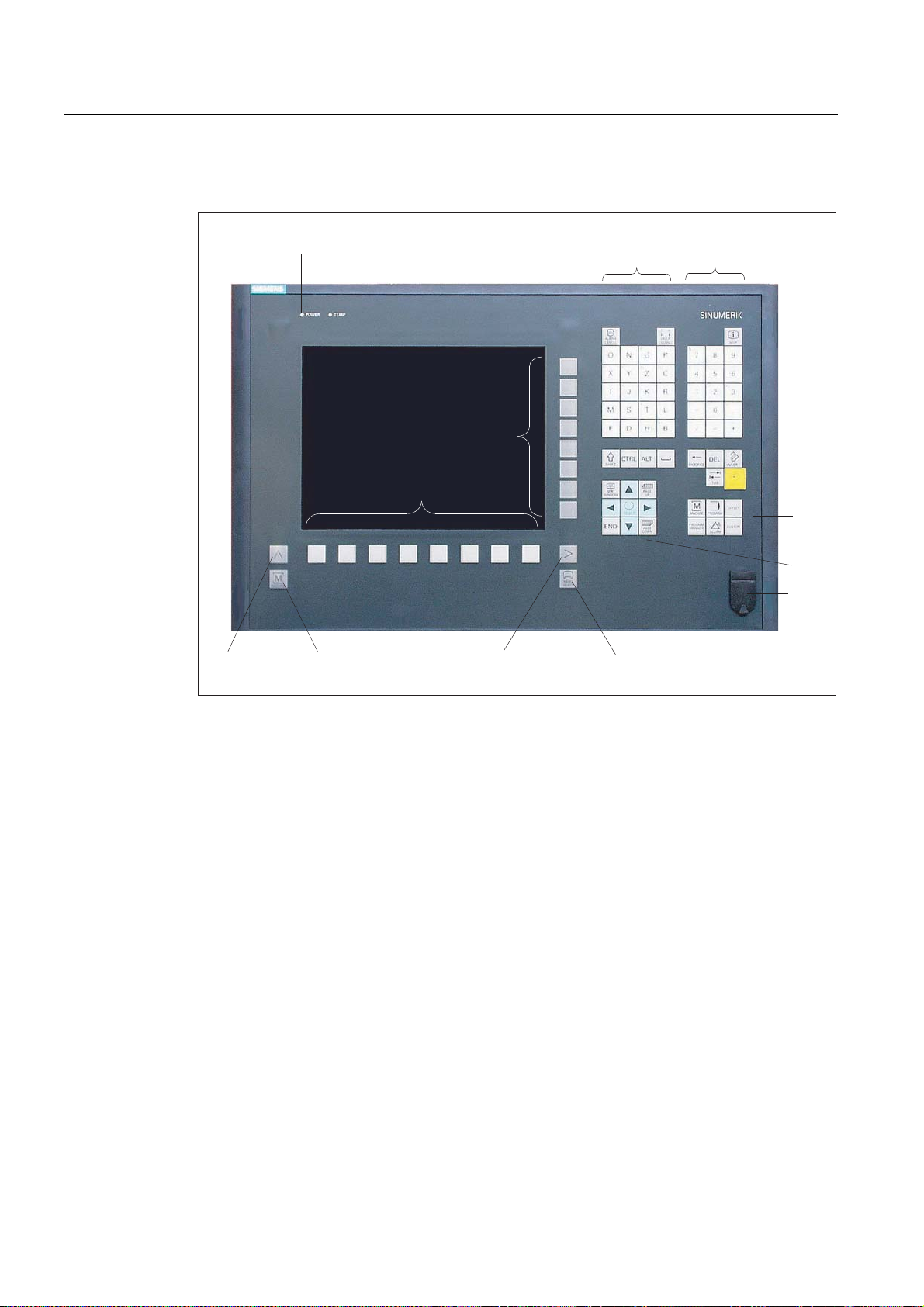
Introduction
1.2 Operator panel fronts
Operator controls and indicators
(5)
(5)
1 Status LED: POWER
2 Status LED: TEMP
(illuminated LEDs indicate increased wear)
3 Alphabetic key group
4 Numerical key group
5 Softkeys
6 Control key group
7 Hotkey group
8 Cursor key group
9 USB interface
10 Menu select key
11 Menu forward button
12 Machine area button
13 Menu back key
Figure 1-1 View of OP 010 operator panel front
Turning
26 Operating Manual, 02/2012, 6FC5398-8CP40-3BA0
Page 27

Introduction
1.2 Operator panel fronts
References
A more precise description as well as a view of the other operator panel fronts that can be
used may be found in the following reference:
Operator Components and Networking Manual; SINUMERIK 840D sl/840Di sl
Turning
Operating Manual, 02/2012, 6FC5398-8CP40-3BA0
27
Page 28

Introduction
1.2 Operator panel fronts
1.2.2 Keys of the operator panel
The following keys and key combinations are available for operation of the controller and the
machine tool.
Keys and key combinations
Key Function
<ALARM CANCEL>
<CHANNEL>
<HELP>
<NEXT WINDOW>
+
<NEXT WINDOW> + <SHIFT>
Cancels alarms and messages that are marked with this
symbol.
Advances for several channels.
Calls the context-sensitive online help for the selected window.
*
Toggles between the windows.
For a multi-channel view or for a multi-channel functionality,
switches within a channel gap between the upper and lower
window.
Selects the first entry in selection lists and in selection fields.
Moves the cursor to the beginning of a text.
* on USB keyboards use the <Home> or <Pos 1> key
Selects the first entry in selection lists and in selection fields.
Moves the cursor to the beginning of a text.
Selects a contiguous selection from the current cursor
position up to the target position.
Selects a contiguous selection from the current cursor
position up to the beginning of a program block.
+
<NEXT WINDOW> + <ALT>
Moves the cursor to the first object.
Moves the cursor in the first column of a table row.
Moves the cursor to the beginning of a program block.
Turning
28 Operating Manual, 02/2012, 6FC5398-8CP40-3BA0
Page 29
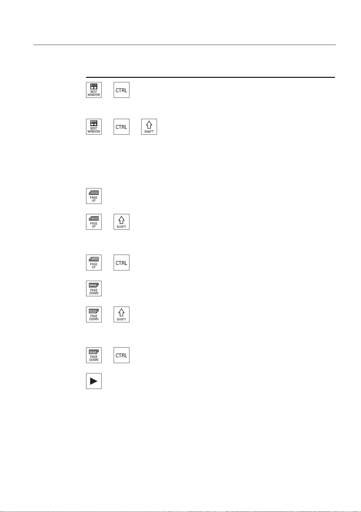
Introduction
1.2 Operator panel fronts
Key Function
+
<NEXT WINDOW> + <CTRL>
Moves the cursor to the beginning of a program.
Moves the cursor in the first row of the current column.
+
+
<NEXT WINDOW> + <CTRL> + <SHIFT>
Moves the cursor to the beginning of a program.
Moves the cursor in the first row of the current column.
Selects a contiguous selection from the current cursor
position up to the target position.
Selects a contiguous selection from the current cursor
position up to the beginning of the program.
<PAGE UP>
+
<PAGE UP> + <SHIFT>
Scrolls upwards by one page in a window.
In the program manager and in the program editor from the
cursor position, selects directories or program blocks up to the
beginning of the window.
+
<PAGE UP> + <CTRL>
Positions the cursor to the topmost line of a window.
<PAGE DOWN>
+
<PAGE DOWN> + <SHIFT>
Scrolls downwards by one page in a window.
In the program manager and in the program editor, from the
cursor position, selects directories or program blocks up to the
end of the window.
+
<PAGE DOWN> + <CTRL>
Positions the cursor to the lowest line of a window.
<Cursor right>
Editing box
Opens a directory or program (e.g. cycle) in the editor.
Navigation
Turning
Operating Manual, 02/2012, 6FC5398-8CP40-3BA0
Moves the cursor further to the right by one character.
29
Page 30
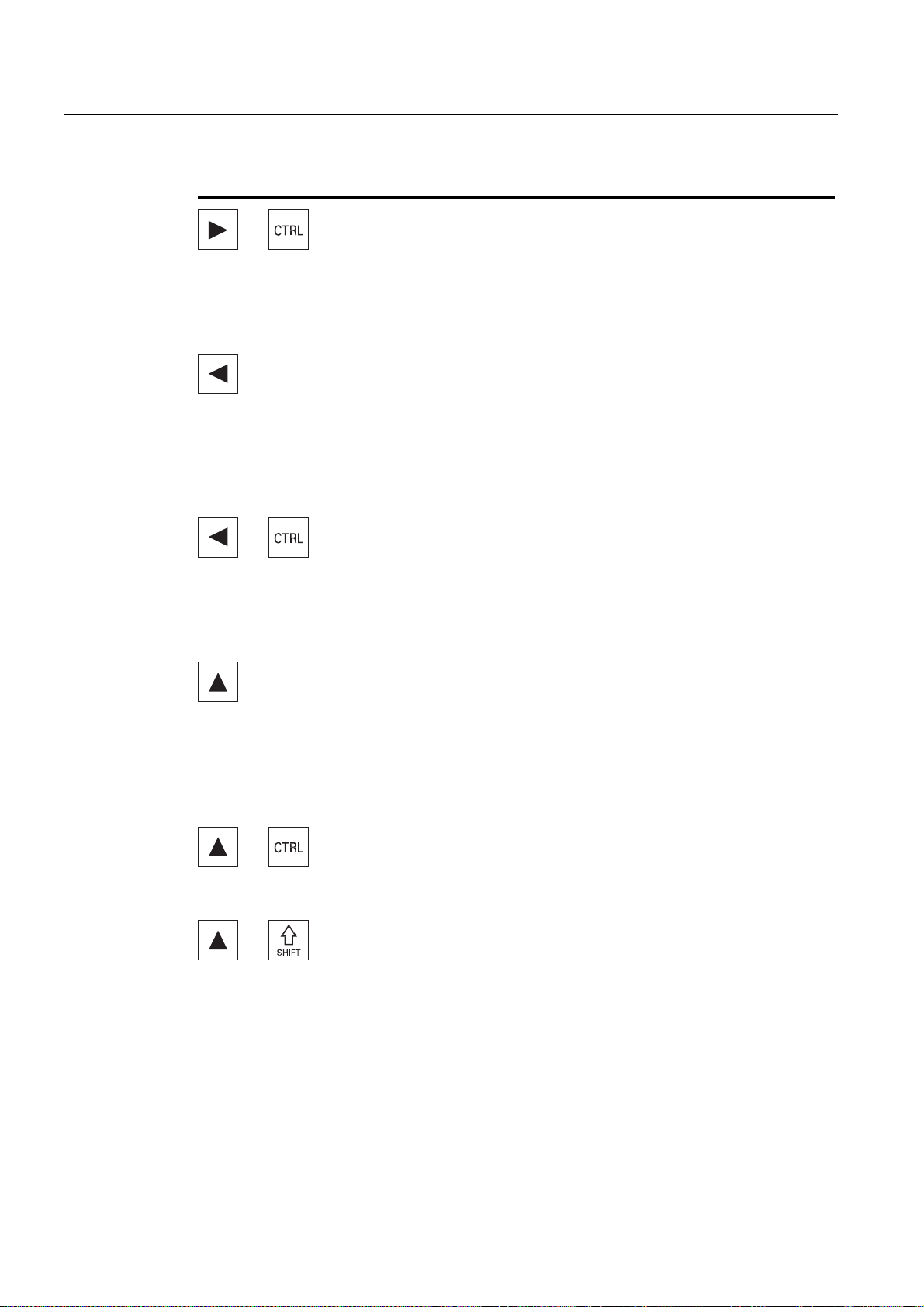
Introduction
1.2 Operator panel fronts
Key Function
+
<Cursor right> + <CTRL>
Editing box
Moves the cursor further to the right by one word.
Navigation
Moves the cursor in a table to the next cell to the right.
<Cursor left>
Editing box
Closes a directory or program (e.g. cycle) in the program
editor. If you have made changes, then these are accepted.
Navigation
Moves the cursor further to the left by one character.
+
<Cursor left> + <CTRL>
Editing box
Moves the cursor further to the left by one word.
Navigation
Moves the cursor in a table to the next cell to the left.
<Cursor up>
Editing box
Moves the cursor into the next upper field.
Navigation
– Moves the cursor in a table to the next cell upwards.
– Moves the cursor upwards in a menu screen.
+
<Cursor up> + <CTRL>
Moves the cursor in a table to the beginning of the table.
Moves the cursor to the beginning of a window.
+
<Cursor up> + <SHIFT>
In the program manager and in the program editor, selects a
contiguous selection of directories and program blocks.
Turning
30 Operating Manual, 02/2012, 6FC5398-8CP40-3BA0
Page 31
Introduction
1.2 Operator panel fronts
Key Function
<Cursor down>
Editing box
Moves the cursor downwards.
Navigation
– Moves the cursor in a table to the next cell downwards.
– Moves the cursor in a window downwards.
+
<Cursor down> + <CTRL>
Navigation
– Moves the cursor in a table to the end of the table.
– Moves the cursor to the end of a window.
Simulation
Reduces the override.
+
<Cursor down> + <SHIFT>
In the program manager and in the program editor, selects a
contiguous selection of directories and program blocks.
<SELECT>
Switches between several specified options in selection dropdown list boxes and in selection boxes.
Activates checkboxes.
In the program editor and in the program manager, selects a
program block or a program.
+
+
<SELECT> + <CTRL>
When selecting table rows, switches between selected and not
selected.
<SELECT> + <SHIFT>
Selects in selection lists and in selection fields the previous
entry or the last entry.
<END>
Moves the cursor to the last entry field in a window, to the end
of a table or a program block.
Selects the last entry in selection lists and in selection fields.
+
<END> + <SHIFT>
Moves the cursor to the last entry.
Selects a contiguous selection from the cursor position up to the
end of a program block.
Turning
Operating Manual, 02/2012, 6FC5398-8CP40-3BA0
31
Page 32

Introduction
1.2 Operator panel fronts
Key Function
+
<END> + <CTRL>
Moves the cursor to the last entry in the last line of the actual
column or to the end of a program.
+
+
<END> + <CTRL> + <SHIFT>
Moves the cursor to the last entry in the last line of the actual
column or to the end of a program.
Selects a contiguous selection from the cursor position up to the
end of a program block.
<BACKSPACE>
Editing box
Deletes a character selected to the left of the cursor.
Navigation
Deletes all of the selected characters to the left of the cursor.
+
<BACKSPACE> + <CTRL>
Editing window
Deletes a word selected to the left of the cursor.
Navigation
Deletes all of the selected characters to the left of the cursor.
<TAB>
+
<TAB> + <SHIFT>
<TAB> + <CTRL>
In the program editor, indents the cursor by one character.
In the program manager, moves the cursor to the next entry
to the right.
In the program editor, indents the cursor by one character.
In the program manager, moves the cursor to the next entry
to the left.
In the program editor, indents the cursor by one character.
In the program manager, moves the cursor to the next entry
to the right.
<TAB> + <SHIFT> + <CTRL>
In the program editor, indents the cursor by one character.
In the program manager, moves the cursor to the next entry
to the left.
Turning
32 Operating Manual, 02/2012, 6FC5398-8CP40-3BA0
Page 33

Introduction
1.2 Operator panel fronts
Key Function
+
$
<CTRL> + <A>
In the actual window, selects all entries (only in the program
editor and program manager).
+
&
+
(
+
)
<CTRL> + <C>
Copies the selected content.
<CTRL> + <E>
Calls the "Ctrl Energy" function.
<CTRL> + <F>
Opens the search dialog in the machine data and setting data
lists, when loading and saving in the MDA editor as well as in
the program manager and in the system data.
+
/
+
<CTRL> + <L>
+
Scrolls the actual user interface through all installed languages
one after the other.
<CTRL> + <SHIFT> + <L>
/
Scrolls the actual operator interface through all installed
languages in the inverse sequence.
+
3
<CTRL> + <P>
Generates a screenshot from the actual operator interface and
saves it as file.
+
6
+
9
<CTRL> + <S>
Switches the single block in or out in the simulation.
<CTRL> + <V>
Pastes the text from the clipboard at the actual cursor
position.
Pastes text from the clipboard at the position of a selected
text.
+
;
+
<
+
=
Turning
Operating Manual, 02/2012, 6FC5398-8CP40-3BA0
<CTRL> + <X>
<CTRL> + <Y>
<CTRL> + <Z>
Cuts out the selected text. The text is located in the clipboard.
Reactivates changes that were undone (only in the program
editor).
Undoes the last action (only in the program editor).
33
Page 34
Introduction
1.2 Operator panel fronts
Key Function
+
+
<CTRL> + <ALT> + <C>
&
Creates a complete standard archive (.ARC) on an external
data carrier (USB-FlashDrive) (for 840D sl / 828D).
Note:
Please refer to the machine manufacturer's specifications.
+
+
<CTRL> + <ALT> + <S>
6
Creates a complete standard archive (.ARC) on an external
data carrier (USB-FlashDrive) (for 840D sl).
Creates a complete Easy Archive (.ARD) on an external data
carrier (USB-FlashDrive) (for 828D).
Note:
Please refer to the machine manufacturer's specifications.
+
+
<CTRL> + <ALT> + <D>
'
Backs up the log files on the USB-FlashDrive. If a USBFlashDrive is not inserted, then the files are backed-up in the
manufacturer's area of the CF card.
+
+
<SHIFT> + <ALT> + <D>
'
Backs up the log files on the USB-FlashDrive. If a USBFlashDrive is not inserted, then the files are backed-up in the
manufacturer's area of the CF card.
+
+
+
+
+
<SHIFT> + <ALT> + <T>
7
Starts "HMI Trace".
<SHIFT> + <ALT> + <T>
7
Exits "HMI Trace".
<ALT> + <S>
6
Opens the editor to enter Asian characters.
<DEL>
Editing box
Deletes the first character right of the cursor.
Navigation
Deletes all characters.
+
<DEL> + <CTRL>
Editing box
Deletes the first word to the right of the cursor.
Navigation
Deletes all characters.
Turning
34 Operating Manual, 02/2012, 6FC5398-8CP40-3BA0
Page 35

Introduction
1.2 Operator panel fronts
Key Function
<Spacebar>
Editing window
Inserts a space
Switches between several specified options in selection
drop-down list boxes and in selection boxes.
<Plus>
Opens a directory which contains the element.
Increases the size of the graphic view for simulation and
traces.
<Minus>
Closes a directory which contains the element.
Reduces the size of the graphic view for simulation and
traces.
<Equals>
Opens the calculator in the entry fields.
<Asterisk>
Opens a directory with all of the subdirectories.
<Tilde>
a
Changes the sign of a number between plus and minus.
<INSERT>
Opens an editing window in the insert mode. Pressing the
key again, exits the window and the entries are undone.
Opens a selection box and shows the selection possibilities.
In the machining step program, enters an empty line for G
code.
+
<INSERT> + <SHIFT>
For G code programming, for a cycle call activates or
deactivates the edit mode.
Turning
Operating Manual, 02/2012, 6FC5398-8CP40-3BA0
35
Page 36

Introduction
1.2 Operator panel fronts
Key Function
<INPUT>
Completes input of a value in the entry field.
Opens a directory or a program.
Inserts an empty program block if the cursor is positioned at
the end of a program block.
Inserts a character to select a new line and the program
block is split up into two parts.
In the G code, inserts a new line after the program block.
In the machining step program, inserts a new line for G code.
<ALARM> - only OP 010 and OP 010C
Select the "Diagnosis" operating area.
<PROGRAM> - only OP 010 and OP 010C
Calls the "Program Manager" operating area.
<OFFSET> - only OP 010 and OP 010C
Calls the "Parameter" operating area.
<PROGRAM MANAGER> - only OP 010 and OP 010C
Calls the "Program Manager" operating area.
Menu forward key
Advances in the extended horizontal softkey bar.
Menu back key
Returns to the higher-level menu.
<MACHINE>
Calls the "Machine" operating area.
<MENU SELECT>
Calls the main menu to select the operating area.
Turning
36 Operating Manual, 02/2012, 6FC5398-8CP40-3BA0
Page 37
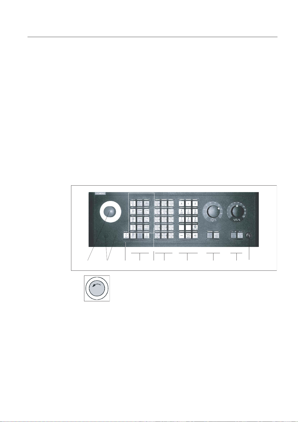
Introduction
1.3 Machine control panels
1.3 Machine control panels
1.3.1 Overview
The machine tool can be equipped with a machine control panel by Siemens or with a
specific machine control panel from the machine manufacturer.
You use the machine control panel to initiate actions on the machine tool such as traversing
an axis or starting the machining of a workpiece.
1.3.2 Controls on the machine control panel
In this example, the MCP 483C IE machine control panel is used to illustrate the operator
controls and displays of a Siemens machine control panel.
Overview
(1)
Turning
Operating Manual, 02/2012, 6FC5398-8CP40-3BA0
EMERGENCY STOP button
Activate the button in situations where
life is at risk.
there is the danger of a machine or workpiece being damaged.
All drives will be stopped with the greatest possible braking torque.
37
Page 38
Introduction
1.3 Machine control panels
(2) Installation locations for control devices (d = 16 mm)
(3)
(4) Program control
(5) Operating modes, machine functions
Machine manufacturer
For additional responses to pressing the Emergency Stop button, please
refer to the machine manufacturer's instructions.
RESET
Stop processing the current programs.
The NCK control remains synchronized with the machine. It is in its initial
state and ready for a new program run.
Cancel alarm.
<SINGLE BLOCK>
Single block mode on/off.
<CYCLE START>
The key is also referred to as NC Start.
Execution of a program is started.
<CYCLE STOP>
The key is also referred to as NC Stop.
Execution of a program is stopped.
<JOG>
Select "JOG" mode.
...
<TEACH IN>
Select "Teach In" submode.
<MDI>
Select "MDI" mode.
<AUTO>
Select "AUTO" mode.
<REPOS>
Repositions, re-approaches the contour.
<REF POINT>
Approach reference point.
Inc <VAR>(Incremental Feed Variable)
Incremental mode with variable increment size.
Inc (incremental feed)
Incremental mode with predefined increment size of 1, ..., 10000
increments.
Turning
38 Operating Manual, 02/2012, 6FC5398-8CP40-3BA0
Page 39
Introduction
1.3 Machine control panels
(6) Customer keys
T1 to T15
(7) Traversal axes with rapid traverse superposition and coordinate exchange
;
...
=
Axis keys
Selects an axis.
Machine manufacturer
A machine data code defines how the increment value is
interpreted.
...
Direction keys
Select the traversing direction.
<RAPID>
Traverse axis in rapid traverse while pressing the direction key.
(8) Spindle control with override switch
(9) Feed control with override switch
(10) Keyswitch (four positions)
Figure 1-2 Front view of machine control panel (milling version)
<WCS MCS>
Switches between the workpiece coordinate system (WCS) and machine
coordinate system (MCS).
<SPINDLE STOP>
Stop spindle.
<SPINDLE START>
Spindle is enabled.
<FEED STOP>
Stops execution of the running program and shuts down axis drives.
<FEED START>
Enable for program execution in the current block and enable for ramp-up to
the feedrate value specified by the program.
Turning
Operating Manual, 02/2012, 6FC5398-8CP40-3BA0
39
Page 40
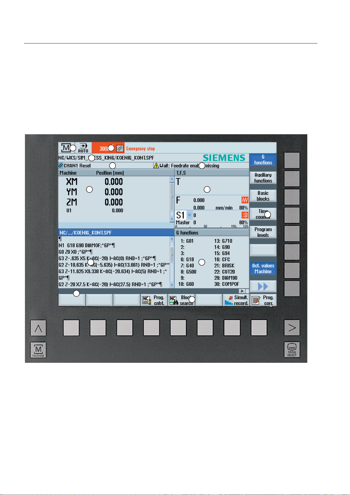
Introduction
1.4 User interface
1.4 User interface
1.4.1 Screen layout
Overview
1 Active operating area and mode
2 Alarm/message line
3 Program name
4 Channel state and program control
5 Channel operational messages
6 Axis position display in actual value window
Turning
40 Operating Manual, 02/2012, 6FC5398-8CP40-3BA0
Page 41

Introduction
1.4 User interface
7 Display for
active tool T
current feedrate F
active spindle with current status (S)
Spindle utilization rate in percent
8 Operating window with program block display
9 Display of active G functions, all G functions, H functions and input window for different functions (for example, skip
blocks, program control)
10 Dialog line to provide additional user notes
11 Horizontal softkey bar
12 Vertical softkey bar
Figure 1-3 User interface
1.4.2 Status display
The status display includes the most important information about the current machine status
and the status of the NCK. It also shows alarms as well as NC and PLC messages.
Depending on your operating area, the status display is made up of several lines:
● Large status display
The status display is made up of three lines in the "Machine" operating area.
● Small status display
In the "Parameter", "Program", "Program Manager", "Diagnosis" and "Start-up" operating
areas, the status display consists of the first line from the large display.
Status display of "Machine" operating area
First line
Display Description
Active operating area
"Machine" operating area
With touch operation, you can change the operating area here.
Turning
Operating Manual, 02/2012, 6FC5398-8CP40-3BA0
"Parameter" operating area
"Program" operating area
41
Page 42
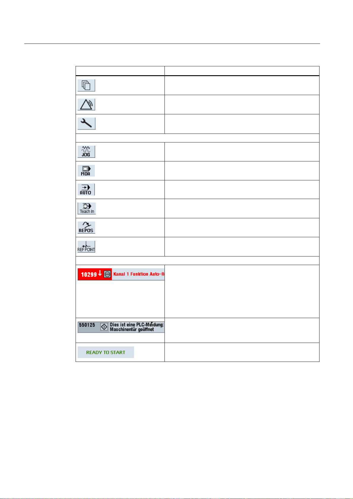
Introduction
1.4 User interface
Display Description
"Program manager" operating area
"Diagnosis" operating area
"Start-up" operating area
Active mode or submode
"Jog" mode
"MDA" mode
"Auto" mode
"Teach In" submode
Alarms and messages
"Repos" submode
"Ref Point" submode
Alarm display
The alarm numbers are displayed in white lettering on a red
background. The associated alarm text is shown in red
lettering.
An arrow indicates that several alarms are active.
An acknowledgment symbol indicates that the alarm can be
acknowledged or canceled.
NC or PLC message
Message numbers and texts are shown in black lettering.
An arrow indicates that several messages are active.
Messages from NC programs do not have numbers and appear
in green lettering.
Turning
42 Operating Manual, 02/2012, 6FC5398-8CP40-3BA0
Page 43
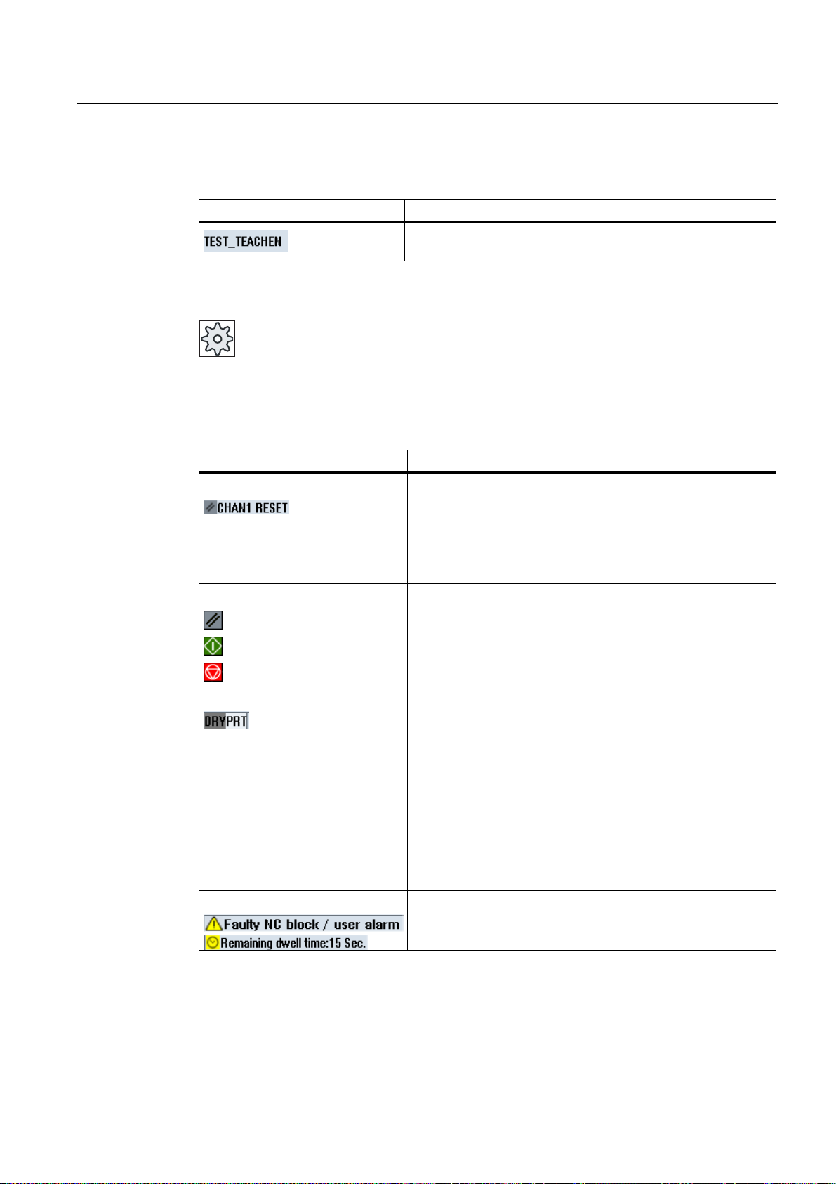
Introduction
1.4 User interface
Second line
Display Description
Program path and program name
The displays in the second line can be configured.
Machine manufacturer
Please also refer to the machine manufacturer's instructions.
Third line
Display Description
Display of channel status.
If several channels are present on the machine, the channel
name is also displayed.
If only one channel is available, only the "Reset" channel status
is displayed.
With touch operation, you can change the channel here.
Display of channel status:
The program was aborted with "Reset".
The program is started.
The program has been interrupted with "Stop".
Display of active program controls:
PRT: no axis motion
DRY: Dry run feedrate
RG0: reduced rapid traverse
M01: programmed stop 1
M101: programmed stop 2 (name varies)
SB1: Single block, coarse (program stops only after blocks
which perform a machine function)
SB2: Data block (program stops after each block)
SB3: Single block, fine (program also only stops after blocks
which perform a machine function in cycles)
Channel operational messages:
Stop: An operator action is usually required.
Wait: No operator action is required.
The machine manufacturer settings determine which program controls are displayed.
Turning
Operating Manual, 02/2012, 6FC5398-8CP40-3BA0
43
Page 44

Introduction
1.4 User interface
Machine manufacturer
Please also refer to the machine manufacturer's instructions.
1.4.3 Actual value window
The actual values of the axes and their positions are displayed.
Work/Machine
The displayed coordinates are based on either the machine coordinate system or the
workpiece coordinate system. The machine coordinate system (Machine), in contrast to the
workpiece coordinate system (Work), does not take any work offsets into consideration.
You can use the "Machine actual values" softkey to toggle between the machine coordinate
system and the workpiece coordinate system.
Maximize display
The actual value display of the positions can also refer to the SZS coordinate system
(settable zero system). However the positions are still output in the Work.
The ENS coordinate system corresponds to the Work coordinate system, reduced by certain
components ($P_TRAFRAME, $P_PFRAME, $P_ISO4FRAME, $P_CYCFRAME), which are
set by the system when machining and are then reset again. By using the ENS coordinate
system, jumps into the actual value display are avoided, that would otherwise be caused by
the additional components.
Machine manufacturer
Please refer to the machine manufacturer's specifications.
Press the ">>" and "Zoom act.val." softkeys.
Turning
44 Operating Manual, 02/2012, 6FC5398-8CP40-3BA0
Page 45

Introduction
1.4 User interface
Overview of display
Display Meaning
Header columns
Work/Machine Display of axes in selected coordinate system.
Item Position of displayed axes.
Display of distance-to-go The distance-to-go for the current NC block is displayed while the
program is running.
Feed/override The feed acting on the axes, as well as the override, are displayed
in the full-screen version.
Repos offset The distances traversed in manual mode are displayed.
This information is only displayed when you are in the "Repos"
submode.
Footer Display of active work offsets and transformations.
The T, F, S values are also displayed in the full-screen version.
See also
Zero offsets (Page 84)
1.4.4 T,F,S window
The most important data concerning the current tool, the feedrate (path feed or axis feed in
JOG) and the spindle are displayed in the T, F, and S windows.
Tool data
Display Meaning
T
Tool name Name of current tool
Location Location number of current tool
D Cutting edge of the current tool
H H number (tool offset data record for DIN-ISO mode)
Ø Diameter of current tool
R Radius of the actual tool
The tool is displayed with the associated tool type symbol corresponding to
the actual coordinate system in the selected cutting edge position.
If the tool is swiveled, then this is taken into account in the display of the
cutting edge position.
In DIN-ISO mode the H number is displayed instead of the cutting edge
number.
If there is a valid D number, this is also displayed.
Turning
Operating Manual, 02/2012, 6FC5398-8CP40-3BA0
45
Page 46
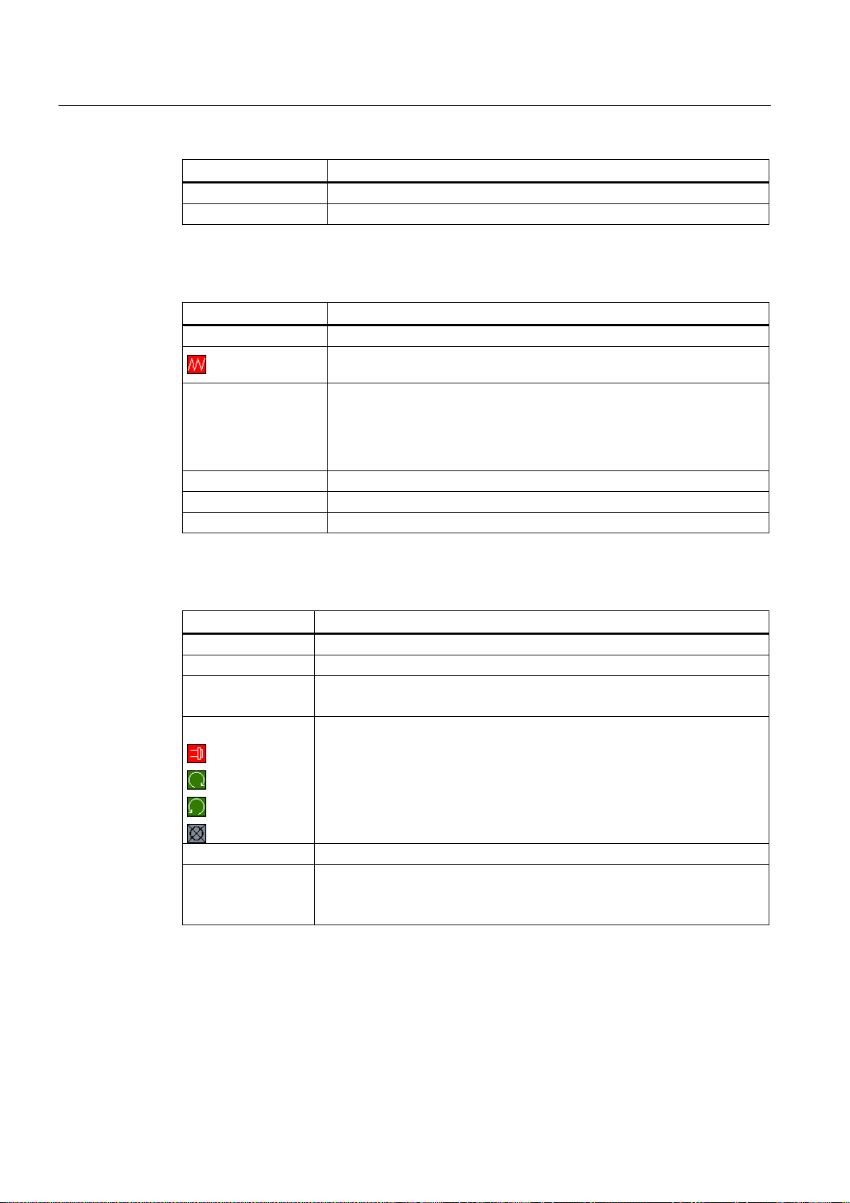
Introduction
1.4 User interface
Display Meaning
Z Z value of the actual tool
X X value of the actual tool
Feed data
Display Meaning
F
Actual feed value
Rapid traverse G0 is active
0.000 No feed is active
Override Display as a percentage
Feed disable
If several axes traverse, is displayed for:
"JOG" mode: Axis feed for the traversing axis
"MDA" and "AUTO" mode: Programmed axis feed
Spindle data
Display Meaning
S
S1 Spindle selection, identification with spindle number and main spindle
Speed Actual value (when spindle turns, display increases)
Setpoint (always displayed, also during positioning)
Symbol
Override Display as a percentage
Spindle utilization
rate
Spindle status
Spindle not enabled
Spindle is turning clockwise
Spindle is turning counterclockwise
Spindle is stationary
Display between 0 and 100%
The upper limit value can be greater than 100%.
See machine manufacturer's specifications.
Turning
46 Operating Manual, 02/2012, 6FC5398-8CP40-3BA0
Page 47

Introduction
1.4 User interface
1.4.5 Current block display
The window of the current block display shows you the program blocks currently being
executed.
Display of current program
The following information is displayed in the running program:
● The workpiece name or program name is entered in the title row.
● The program block which is just being processed appears colored.
Editing a program directly
In the Reset state, you can edit the current program directly.
1. Press the <INSERT> key.
2. Place the cursor at the relevant position and edit the program block.
Direct editing is only possible for G code blocks in the NC memory, not
for external execution.
3. Press the <INSERT> key to exit the program and the edit mode again.
1.4.6 Operation via softkeys and buttons
Operating areas/operating modes
The user interface consists of different windows featuring eight horizontal and eight vertical
softkeys.
You operate the softkeys with the keys next to the softkey bars.
You can display a new window or execute functions using the softkeys.
The operating software is sub-divided into six operating areas (machine, parameter,
program, program manager, diagnosis, startup) and five operating modes or submodes
(JOG, MDA, AUTO, TEACH IN, REF POINT, REPOS).
Turning
Operating Manual, 02/2012, 6FC5398-8CP40-3BA0
47
Page 48
Introduction
1.4 User interface
Changing the operating area
Press the <MENU SELECT> key and select the desired operating area using
You can call the "Machine" operating area directly using the key on the operator panel.
Changing the operating mode
You can select a mode or submode directly using the keys on the machine control panel or
using the vertical softkeys in the main menu.
the horizontal softkey bar.
Press the <MACHINE> key to select the "machine" operating area.
General keys and softkeys
When the
interface, you can change the horizontal softkey bar within an operating area.
To do so, press the menu forward key.
The
symbol indicates that you are in the expanded softkey bar.
Pressing the key again will take you back to the original horizontal softkey bar.
Use the ">>" softkey to open a new vertical softkey bar.
Use the "<<" softkey to return to the previous vertical softkey bar.
Use the "Return" softkey to close an open window.
Use the "Cancel" softkey to exit a window without accepting the entered
values and return to the next highest window.
When you have entered all the necessary parameters in the parameter screen
form correctly, you can close the window and save the parameters using the
"Accept" softkey. The values you entered are applied to a program.
Use the "OK" softkey to initiate an action immediately, e.g. to rename or
delete a program.
symbol appears to the right of the dialog line on the user
Turning
48 Operating Manual, 02/2012, 6FC5398-8CP40-3BA0
Page 49

Introduction
1.4 User interface
1.4.7 Entering or selecting parameters
When setting up the machine and during programming, you must enter various parameter
values in the entry fields. The background color of the fields provides information on the
status of the entry field.
Orange background The input field is selected
Light orange background The input field is in edit mode
Pink background The entered value is incorrect
Selecting parameters
Some parameters require you to select from a number of options in the input field. Fields of
this type do not allow you to type in a value.
Procedure
The selection symbol is displayed in the tooltip:
Associated selection fields
There are selection fields for various parameters:
● Selection of units
● Changeover between absolute and incremental dimensions
1. Keep pressing the <SELECT> key until the required setting or unit is
selected.
The <SELECT> key only works if there are several selection options
available.
- OR -
Press the <INSERT> key.
The selection options are displayed in a list.
2. Select the required setting using the <Cursor down> and <Cursor up>
keys.
3. If required, enter a value in the associated input field.
4. Press the <INPUT> key to complete the parameter input.
Turning
Operating Manual, 02/2012, 6FC5398-8CP40-3BA0
49
Page 50
Introduction
1.4 User interface
Changing or calculating parameters
If you only want to change individual characters in an input field rather than overwriting the
entire entry, switch to insertion mode.
In this mode, you can also enter simple calculation expressions, without having to explicitly
call the calculator. You can execute the four basic calculation types, work with expressions in
brackets as well as generate square roots and squares.
Note
Generating square roots and squares
The extract roots and generate square functions is not available in the parameter screens of
the cycles and functions in the "Program" operating area.
Press the <INSERT> key.
The insert mode is activated.
You can navigate within the input field using the <Cursor left> and
<Cursor right> keys.
Use the <BACKSPACE> and <DEL> key to delete individual characters.
+ <*> Enter the multiplication characters using the <SHIFT> + <*> keys.
+ </> Enter the division character using the <SHIFT> + </> keys.
Enter bracket expressions using the <SHIFT> + <(> and <SHIFT> + <)>
keys.
+ <)>
+ <number> Enter "r" or "R" as well as the number x from which you would like to
5
extract the root.
Turning
50 Operating Manual, 02/2012, 6FC5398-8CP40-3BA0
Page 51

Introduction
1.4 User interface
+ <number> Enter "s" or "S" as well as the number x for which you would like to
6
generate the square.
Close the value entry using the <INPUT> key and the result is
transferred into the field.
Accepting parameters
When you have correctly entered all necessary parameters, you can close the window and
save your settings.
You cannot accept the parameters if they are incomplete or obviously erroneous. In this
case, you can see from the dialog line which parameters are missing or were entered
incorrectly.
Press the "OK" softkey.
- OR -
Press the "Accept" softkey.
1.4.8 Pocket calculator
You can use the calculator to quickly calculate parameter values during programming. If, for
example, the diameter of a workpiece is only dimensioned indirectly in the workpiece
drawing, i.e., the diameter must be derived from the sum of several other dimension
specifications, you can calculate the diameter directly in the input field of this parameter.
Calculation methods
The following arithmetic operations are available:
● Addition
● Subtraction
● Multiplication
● Division
● Calculation with parentheses
● Square root of x
● x squared
You can input a maximum of 256 characters in a field.
Turning
Operating Manual, 02/2012, 6FC5398-8CP40-3BA0
51
Page 52
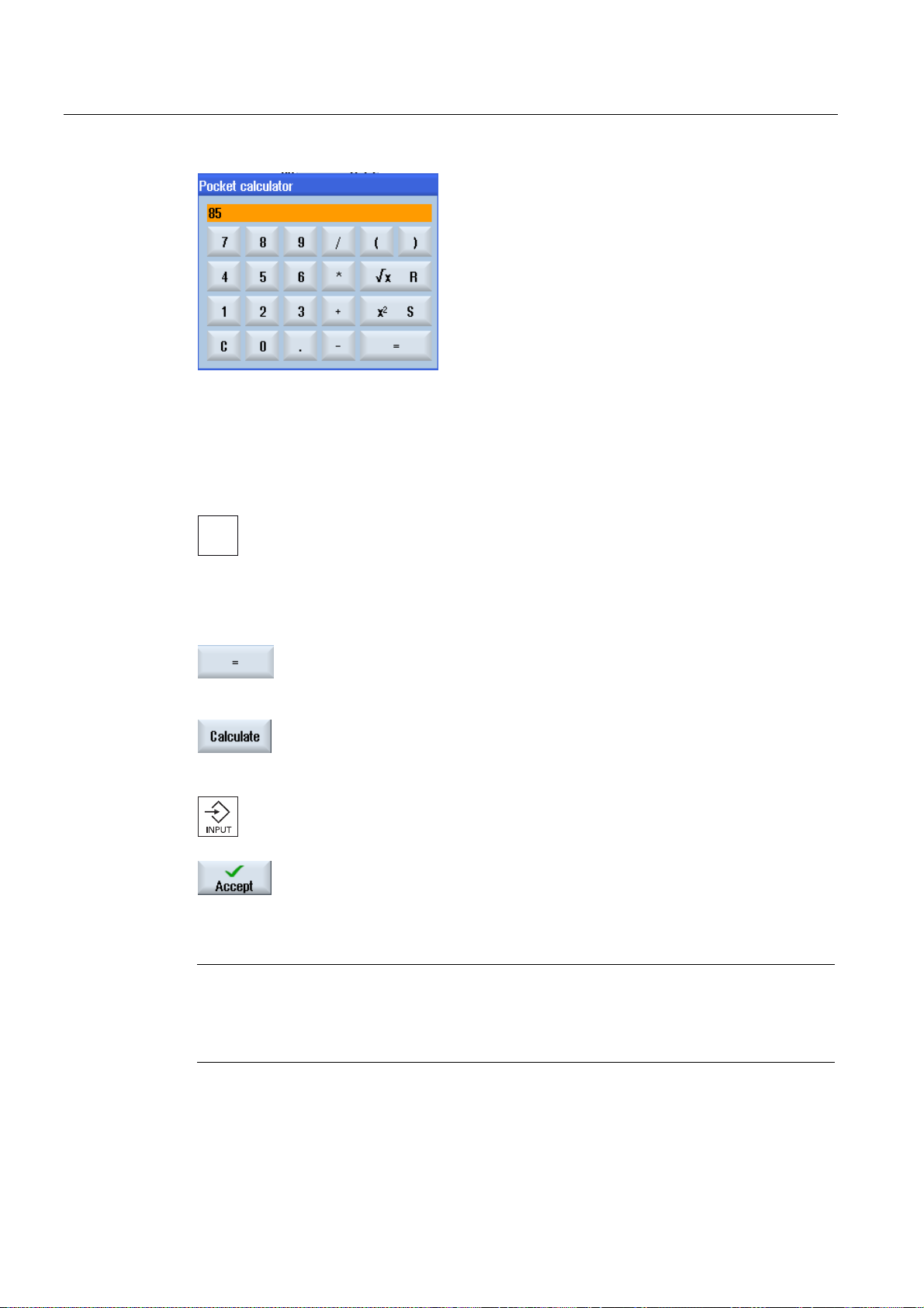
Introduction
1.4 User interface
Procedure
1. Position the cursor on the desired entry field.
2. Press the <=> key.
The calculator is displayed.
3. Input the arithmetic statement.
You can use arithmetic symbols, numbers, and commas.
4. Press the equals symbol on the calculator.
- OR -
Press the "Calculate" softkey.
- OR -
Press the <INPUT> key.
The new value is calculated and displayed in the entry field of the
calculator.
5. Press the "Accept" softkey.
The calculated value is accepted and displayed in the entry field of the
window.
Note
Input order for functions
When using the square root or squaring functions, make sure to press the "R" or "S" function
keys, respectively, before entering a number.
Turning
52 Operating Manual, 02/2012, 6FC5398-8CP40-3BA0
Page 53

Introduction
1.4 User interface
1.4.9 Context menu
When you right-click, the context menu opens and provides the following functions:
● Cut
Cut Ctrl+X
● Copy
Copy Ctrl+C
● Paste
Paste Ctrl+V
Program editor
Additional functions are available in the editor
● Undo the last change
Undo Ctrl+Z
● Redo the changes that were undone
Redo Ctrl+Y
Up to 10 changes can be undone.
1.4.10 Touch operation
If you have an operator panel with a touch screen, you can perform the following functions
with touch operation:
Operating area switchover
You can display the operating area menu by touching the display symbol for
Channel switchover
the active operating area in the status display.
You can switch over to the next channel by touching the channel display
in the status display.
Turning
Operating Manual, 02/2012, 6FC5398-8CP40-3BA0
53
Page 54
Introduction
1.4 User interface
1.4.11 Changing the user interface language
Procedure
1. Select the "Start-up" operating area.
2. Press the "Change language" softkey.
3. Position the cursor on the desired language.
- OR -
The "Language selection" window opens. The language set last is
selected.
4. Press the "OK" softkey.
Press the <INPUT> key.
The user interface changes to the selected language.
Note
Changing the language directly on the input screens
You can switch between the user interface languages available on the controller directly on
the user interface by pressing the key combination <CTRL + L>.
1.4.12 Entering Asian characters
You have the possibility of entering Asian characters.
Note
Call the input editor with <Alt + S>
The input editor can only be called there where it is permissible to enter Asian characters.
You can select a character by using the Pinyin phonetic notation, which enables Chinese
characters to be expressed by combining Latin letters.
Turning
54 Operating Manual, 02/2012, 6FC5398-8CP40-3BA0
Page 55
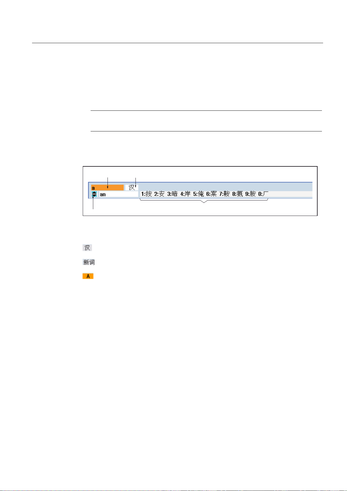
Introduction
1.4 User interface
The editor is available for the following Asian languages:
● Simplified Chinese
● Traditional Chinese
● Korean
Note
You require a special keyboard to enter Korean characters.
Structure of editor
3KRQHWLFLQSXW
3KRQHWLFVHOHFWLRQIURPGLFWLRQDU\
)XQFWLRQVHOHFWLRQ
Functions
Pinyin input
Editing of the dictionary
Input of Latin letters
2IIHUHGFKDUDFWHUV
Turning
Operating Manual, 02/2012, 6FC5398-8CP40-3BA0
55
Page 56

Introduction
1.4 User interface
Precondition
The control has been set to Chinese or Korean.
Procedure
Editing characters
1. Open the screen form and position the cursor on the entry field and
$
+
6
2. Enter the desired phonetic notation.
press the <Alt +S> keys.
The editor is displayed.
3. Click the <Cursor down> key to access the dictionary.
4. By keeping the <Cursor down> key pressed, displays all the entered
phonetic notations and the associated selection characters.
5. Press the <BACKSPACE> softkey to delete entered phonetic notations.
6. Press the number key to insert the associated character.
When a character is selected, the editor records the frequency with
which it is selected for a specific phonetic notation and offers this
character at the top of the list when the editor is next opened.
Editing the dictionary
1. Select the dictionary editing function in the selection box.
The editor provides a further line in which the combined characters and
phonetic notations are displayed.
2. Enter the desired phonetic notation in the phonetic input field.
Various characters are displayed for this phonetic notation, from which
you can select a character by entering either of the appropriate number
(1 to 9).
You can toggle the input cursor between the compound phonetic
notations field and the phonetic input field by pressing the <TAB> key.
Combined characters are cancelled via the <BACKSPACE> key.
3. Press the <SELECT> key to take a combined phonetic notation into the
dictionary.
Turning
56 Operating Manual, 02/2012, 6FC5398-8CP40-3BA0
Page 57
Introduction
1.4 User interface
1.4.13 Protection levels
The input and modification of data in the control system is protected by passwords at
sensitive places.
Access protection via protection levels
The input or modification of data for the following functions depends on the protection level
setting:
● Tool offsets
● Zero offsets
● Setting data
● Program creation / program editing
Note
Configuring access levels for softkeys
You have the option of providing softkeys with protection levels or completely hiding
them.
References
Softkeys
For additional information, please refer to the following documentation:
Commissioning Manual SINUMERIK Operate (IM9) / SINUMERIK 840D sl
Machine operating area Protection level
End user
(protection level 3)
Parameters operating area Protection level
Tool management lists
Keyswitch 3
(protection level 4)
Turning
Operating Manual, 02/2012, 6FC5398-8CP40-3BA0
57
Page 58
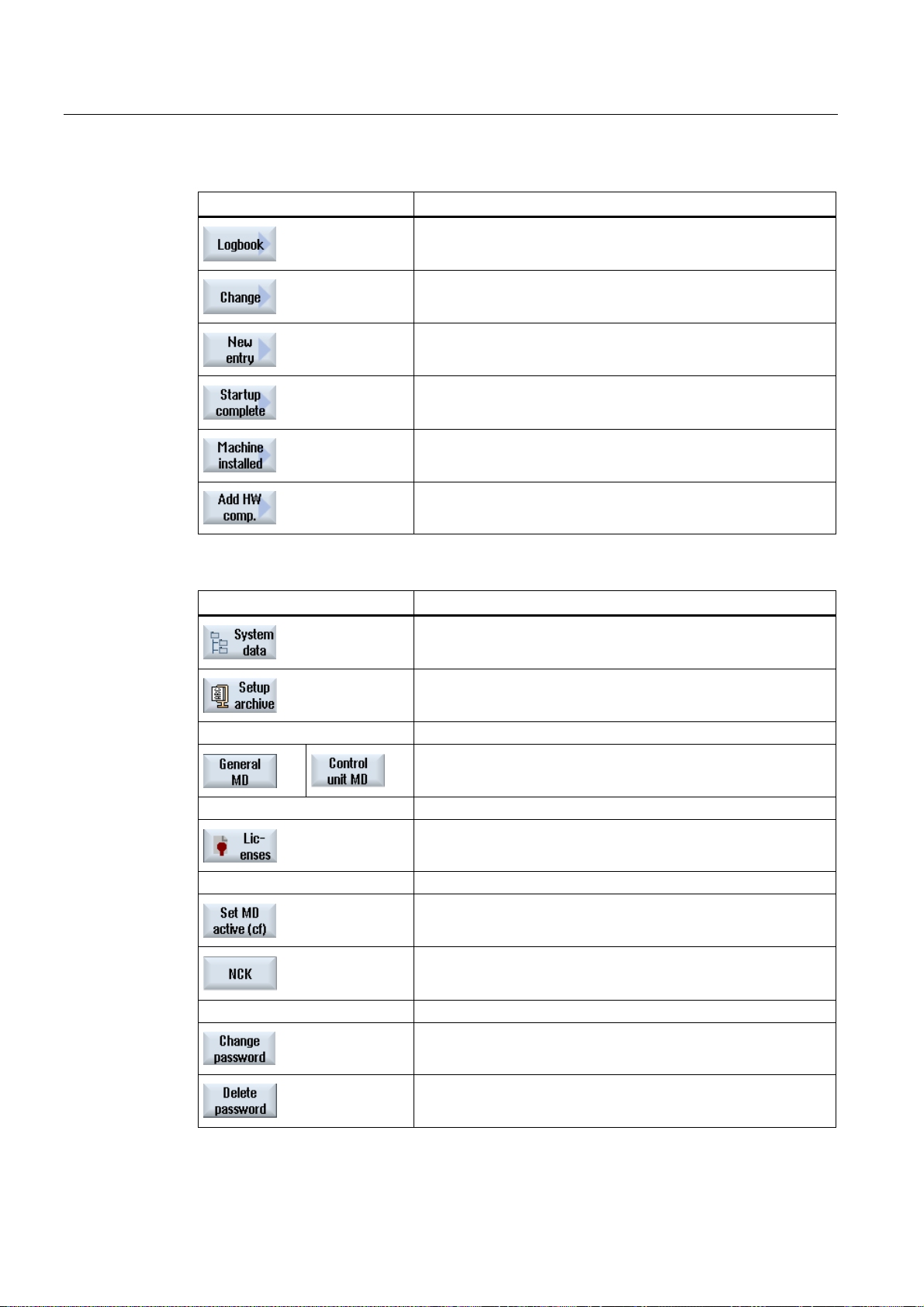
Introduction
1.4 User interface
Diagnostics operating area Protection level
Keyswitch 3
(protection level 4)
User
(protection level 3)
User
(protection level 3)
Manufacturer
(protection level 1)
User
(protection level 3)
Service
(protection level 2)
Start-up operating area Protection levels
End user
(protection level 3)
Keyswitch 3
(protection level 4)
Keyswitch 3
(protection level 4)
Keyswitch 3
(protection level 4)
Keyswitch 3
(protection level 4)
Service
(protection level 2)
End user
(protection level 3)
End user
Turning
(protection level 3)
58 Operating Manual, 02/2012, 6FC5398-8CP40-3BA0
Page 59
Introduction
1.4 User interface
1.4.14 Online help in SINUMERIK Operate
A comprehensive context-sensitive online help is stored in the control system.
● A brief description is provided for each window and, if required, step-by-step instructions
for the operating sequences.
● A detailed help is provided in the editor for every entered G code. You can also display all
G functions and take over a selected command directly from the help into the editor.
● A help page with all parameters is provided on the input screen in the cycle programming.
● Lists of the machine data
● Lists of the setting data
● Lists of the drive parameters
● List of all alarms
Procedure
Calling context-sensitive online help
1. You are in an arbitrary window of an operating area.
2. Press the <HELP> key or on an MF2 keyboard, the <F12> key.
The help page of the currently selected window is opened in a
subscreen.
3. Press the "Full screen" softkey to use the entire user interface for the
display of the online help.
Press the "Full screen" softkey again to return to the subscreen.
4. If further helps are offered for the function or associated topics, position
the cursor on the desired link and press the "Follow reference" softkey.
The selected help page is displayed.
5. Press the "Back to reference" softkey to jump back to the previous help.
Turning
Operating Manual, 02/2012, 6FC5398-8CP40-3BA0
59
Page 60
Introduction
1.4 User interface
Calling a topic in the table of contents
1. Press the "Table of contents" softkey.
Depending on which technology you are using, the Operating Manuals
"Operator control Milling", "Operator control Turning" or "Operator
control Universal" as well as the "Programming" Programming Manual
are displayed.
2. Select the desired manual with the <Cursor down> and <Cursor up>
keys.
3 Press the <Cursor right> or <INPUT> key or double-click to open the
manual and the section.
4. Navigate to the desired topic with the "Cursor down" key.
5. Press the <Follow reference> softkey or the <INPUT> key to display the
help page for the selected topic.
6. Press the "Current topic" softkey to return to the original help.
Searching for a topic
1. Press the "Search" softkey.
The "Search in Help for:" window is opened.
2. Activate the "Full text " checkbox to search in all help pages.
If the checkbox is not activated, a search is performed in the table of
contents and in the index.
3. Enter the desired keyword in the "Text" field and press the "OK" softkey.
If you enter the search term on the operator panel, replace an umlaut
(accented character) by an asterisk (*) as dummy.
All entered terms and sentences are sought with an AND operation. In
this way, only documents and entries that satisfy all the search criteria
are displayed.
4. Press the "Keyword index" softkey if you only want to display the index
of the operating and programming manual.
Turning
60 Operating Manual, 02/2012, 6FC5398-8CP40-3BA0
Page 61
Introduction
1.4 User interface
Displaying alarm descriptions and machine data
1. If messages or alarms are pending in the "Alarms", "Messages" or
"Alarm Log" window, position the cursor at the appropriate display and
press the <HELP> or the <F12> key.
The associated alarm description is displayed.
2. If you are in the "Start-up" operating area in the windows for the display
of the machine, setting and drive data, position the cursor on the
desired machine data or drive parameter and press the <HELP> or the
<F12> key.
The associated data description is displayed.
Displaying and inserting a G code command in the editor
1. A program is opened in the editor.
Position the cursor on the desired G code command and press the
<HELP> or the <F12> key.
The associated G code description is displayed.
2. Press the "Display all G functions" softkey.
3. With the aid of the search function, select, for example, the desired G
code command.
4. Press the "Transfer to editor" softkey.
The selected G function is taken into the program at the cursor position.
5. Press the "Exit help" softkey again to close the help.
Turning
Operating Manual, 02/2012, 6FC5398-8CP40-3BA0
61
Page 62

Introduction
1.4 User interface
Turning
62 Operating Manual, 02/2012, 6FC5398-8CP40-3BA0
Page 63
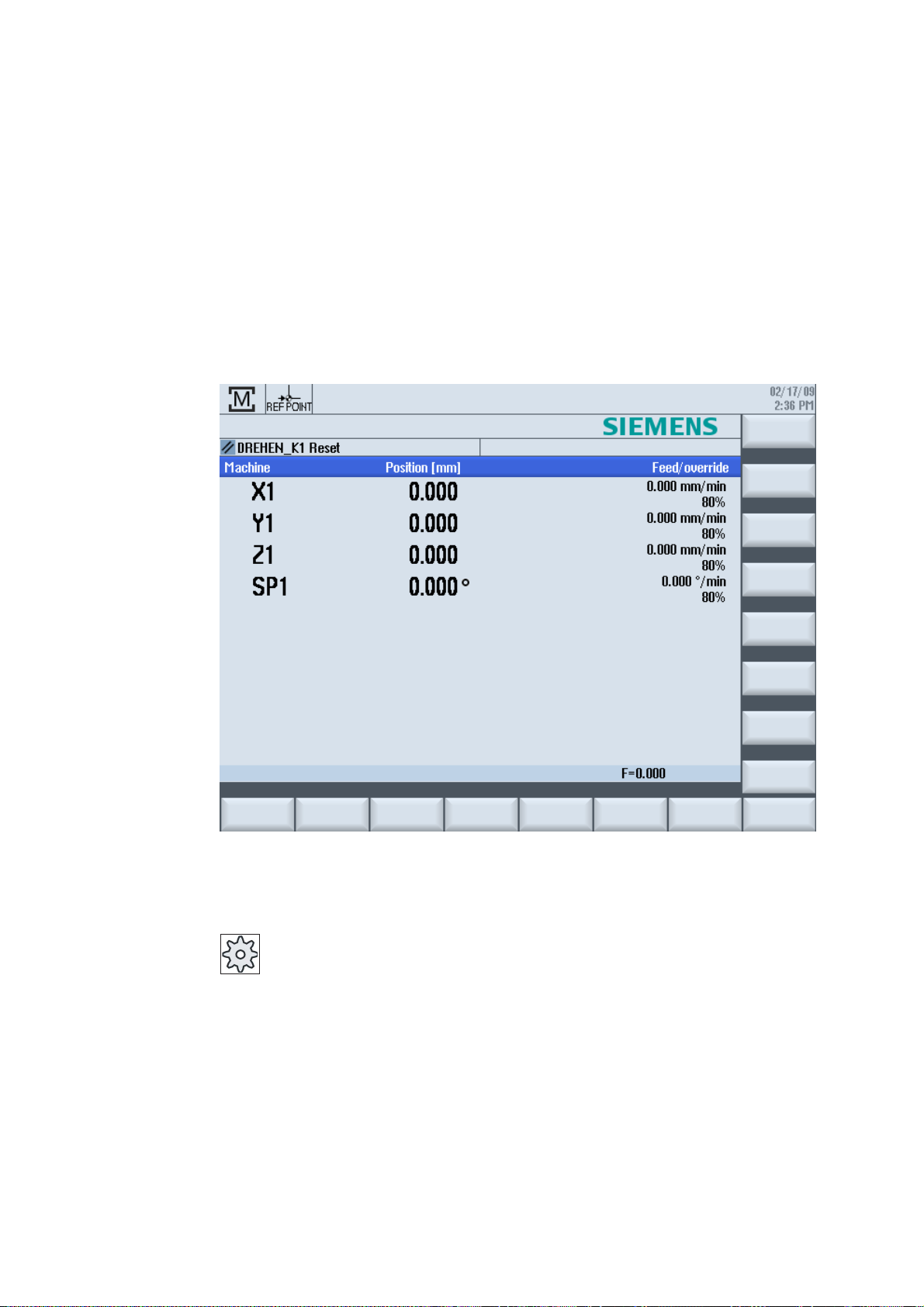
Setting up the machine
2.1 Switching on and switching off
Start-up
2
When the control starts up, the main screen opens according to the operating mode
specified by the machine manufacturer. In general, this is the main screen for the "REF
POINT" submode.
Machine manufacturer
Please also refer to the machine manufacturer's instructions.
Turning
Operating Manual, 02/2012, 6FC5398-8CP40-3BA0
63
Page 64

Setting up the machine
2.2 Approaching a reference point
2.2 Approaching a reference point
2.2.1 Referencing axes
Your machine tool can be equipped with an absolute or incremental path measuring system.
An axis with incremental path measuring system must be referenced after the controller has
been switched on – however, an absolute path measuring system does not have to be
referenced.
For the incremental path measuring system, all the machine axes must therefore first
approach a reference point, the coordinates of which are known to be relative to the machine
zero-point.
Sequence
Prior to the approach, the axes must be in a position from where they can approach the
reference point without a collision.
The axes can also all approach the reference point simultaneously, depending on the
manufacturer’s settings.
Machine manufacturer
Please refer to the machine manufacturer's specifications.
NOTICE
If the axes are not in a collision-free position, you must first traverse them to safe positions
in "JOG" or "MDA" mode.
You must follow the axis motions directly on the machine!
Ignore the actual value display until the axes have been referenced!
The software limit switches are not active!
Turning
64 Operating Manual, 02/2012, 6FC5398-8CP40-3BA0
Page 65

Setting up the machine
2.2 Approaching a reference point
Procedure
1. Press the <JOG> key.
2. Press the <REF. POINT> key.
;
=
The axis is referenced as soon as the reference point is reached. The actual value display is
set to the reference point value.
From now on, path limits, such as software limit switches, are active.
End the function via the machine control panel by selecting operating mode "AUTO" or
"JOG".
3. Select the axis to be traversed.
4. Press the <-> or <+> key.
The selected axis moves to the reference point.
If you have pressed the wrong direction key, the action is not accepted
and the axes do not move.
A symbol is shown next to the axis if it has been referenced.
2.2.2 User agreement
If you are using Safety Integrated (SI) on your machine, you will need to confirm that the
current displayed position of an axis corresponds to its actual position on the machine when
you reference an axis. Your confirmation is the requirement for the availability of other Safety
Integrated functions.
You can only give your user agreement for an axis after it has approached the reference
point.
The displayed axis position always refers to the machine coordinate system (Machine).
Option
User agreement with Safety Integrated is only possible with a software option.
Turning
Operating Manual, 02/2012, 6FC5398-8CP40-3BA0
65
Page 66
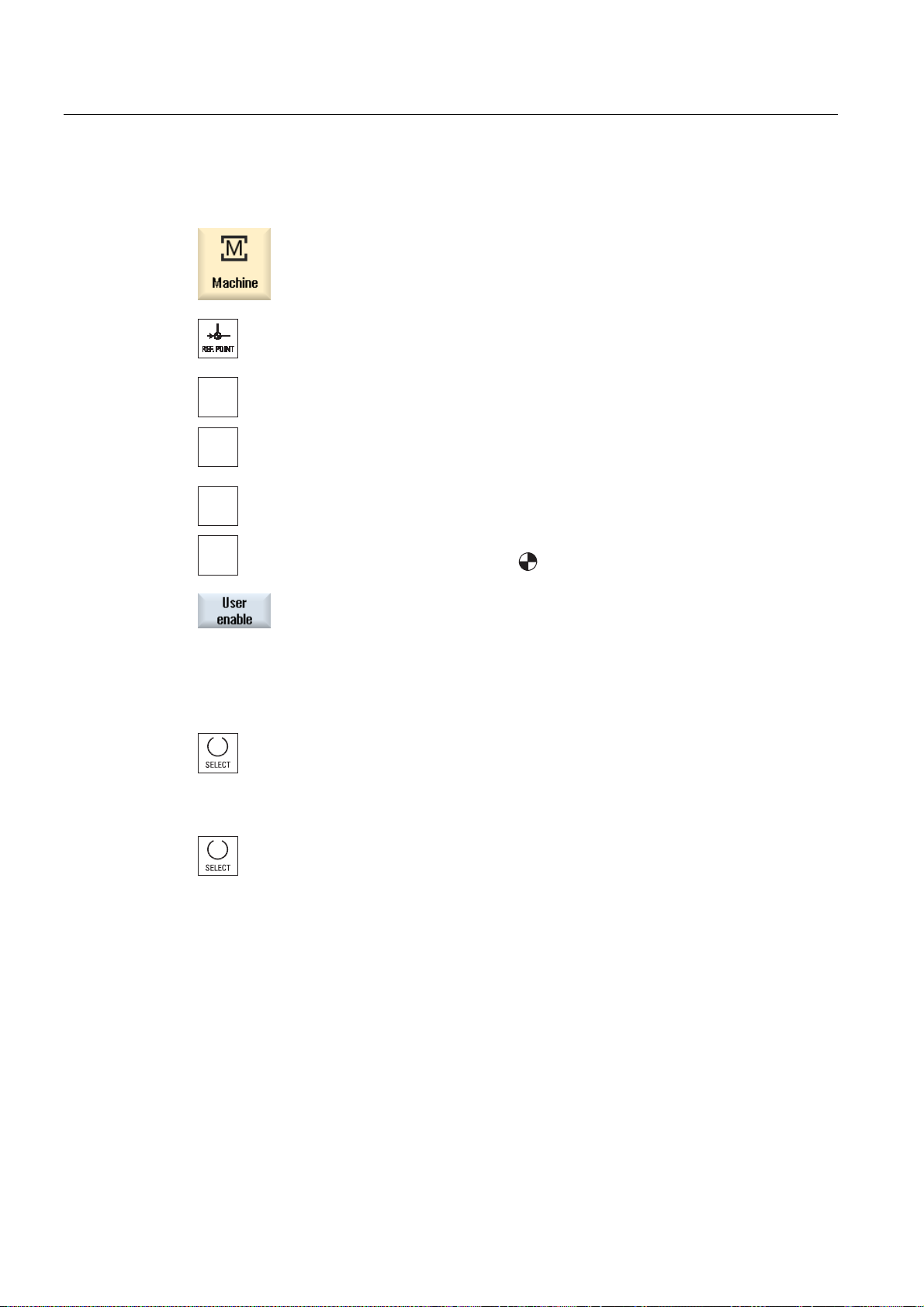
Setting up the machine
2.2 Approaching a reference point
Procedure
1. Select the "Machine" operating area.
2. Press the <REF POINT> key.
;
=
It shows a list of all machine axes with their current position and SI
5. Position the cursor in the "Acknowledgement" field for the axis in
The selected axis is marked with an "x" meaning "safely referenced"
3. Select the axis to be traversed.
4. Press the <-> or <+> key.
The selected axis moves to the reference point and stops. The
coordinate of the reference point is displayed.
The axis is marked with
5. Press the "User enable" softkey.
The "User Agreement" window opens.
position.
question.
6. Activate the acknowledgement with the <SELECT> key.
in the "Acknowledgement" column.
By pressing the <SELECT> key again, you deactivate the
acknowledgement again.
.
Turning
66 Operating Manual, 02/2012, 6FC5398-8CP40-3BA0
Page 67

Setting up the machine
2.3 Modes and mode groups
2.3 Modes and mode groups
2.3.1 General
You can work in three different operating modes.
"JOG" mode
"JOG" mode is used for the following preparatory actions:
● Approach reference point, i.e. the machine axis is referenced
● Preparing a machine for executing a program in automatic mode, i.e. measuring tools,
measuring the workpiece and, if necessary, defining the work offsets used in the program
● Traversing axes, e.g. during a program interruption
● Positioning axes
Select "JOG"
"Ref Point" submode
The "REF POINT" submode is used to synchronize the control and the machine. For this
purpose, you approach the reference point in "JOG" mode.
Selecting "REF POINT"
"REPOS" submode
The "REPOS" submode is used for repositioning to a defined position. After a program
interruption (e.g. to correct tool wear values) move the tool away from the contour in "JOG"
mode.
Press the <JOG> key.
Press the <REF POINT> key.
The distances traversed in "JOG" mode are displayed in the actual value window as the
"Repos" offset.
"REPOS" offsets can be displayed in the machine coordinate system (MCS) or workpiece
coordinate system (WCS).
Turning
Operating Manual, 02/2012, 6FC5398-8CP40-3BA0
67
Page 68

Setting up the machine
2.3 Modes and mode groups
Selecting "Repos"
Press the <REPOS> key.
"MDA" mode (Manual Data Automatic)
In "MDA" mode, you can enter and execute G code commands non-modally to set up the
machine or to perform a single action.
Selecting "MDA"
Press the <MDA> key.
"AUTO" mode
In automatic mode, you can execute a program completely or only partially.
Select "AUTO"
"TEACH IN" submode
The "TEACH IN" submode is available in the "AUTO" and "MDA" modes.
There you may create, edit and execute part programs (main programs or subroutines) for
motional sequences or simple workpieces by approaching and saving positions.
Selecting "Teach In"
Press the <AUTO> key.
Press the <TEACH IN> key.
Turning
68 Operating Manual, 02/2012, 6FC5398-8CP40-3BA0
Page 69

Setting up the machine
2.3 Modes and mode groups
2.3.2 Modes groups and channels
Every channel behaves like an independent NC. A maximum of one part program can be
processed per channel.
● Control with 1channel
One mode group exists.
● Control with several channels
Channels can be grouped to form several "mode groups."
Example
Control with 4 channels, where machining is carried out in 2 channels and 2 other channels
are used to control the transport of the new workpieces.
Mode group 1 channel 1 (machining)
Channel 2 (transport)
Mode group 2 channel 3 (machining)
Channel 4 (transport)
Mode groups (MGs)
Technologically-related channels can be combined to form a mode group.
Axes and spindles of the same mode group can be controlled by one or more channels.
An operating mode group is in one of "Automatic", "JOG" or "MDI" operating modes, i.e.,
several channels of an operating mode group can never assume different operating modes.
2.3.3 Channel switchover
It is possible to switch between channels when several are in use. Since individual channels
may be assigned to different mode groups, a channel switchover command is also an implicit
mode switchover command.
When a channel menu is available, all of the channels are displayed on softkeys and can be
switched over.
Turning
Operating Manual, 02/2012, 6FC5398-8CP40-3BA0
69
Page 70

Setting up the machine
2.3 Modes and mode groups
Changing the channel
Press the <CHANNEL> key.
The channel changes over to the next channel.
- OR -
If the channel menu is available, a softkey bar is displayed. The active
channel is highlighted.
Another channel can be selected by pressing one of the other softkeys.
References
Commissioning Manual SINUMERIK Operate (IM9) / SINUMERIK 840D sl
Channel switchover via touch operation
On the HT 8 and when using a touch screen operator panel, you can switch to the next
channel or display the channel menu via touch operation in the status display.
Turning
70 Operating Manual, 02/2012, 6FC5398-8CP40-3BA0
Page 71
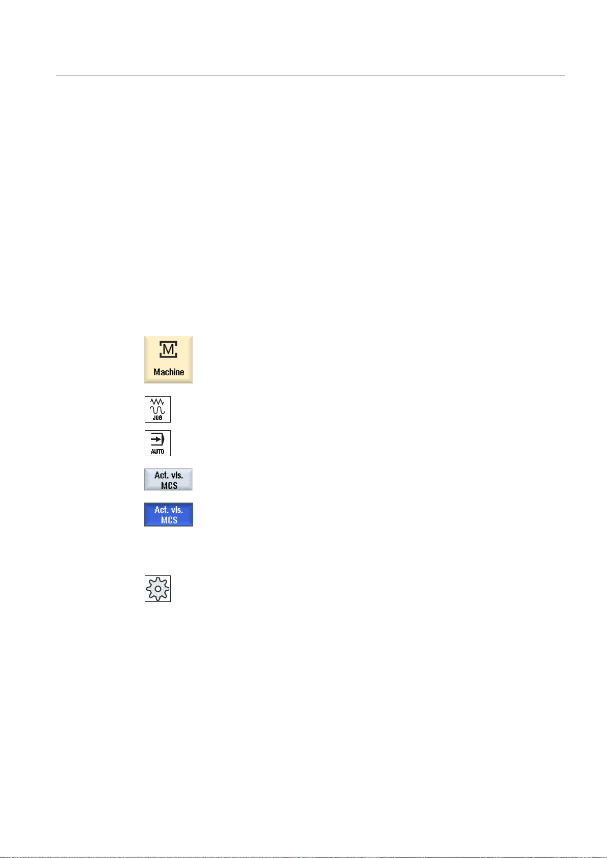
Setting up the machine
2.4 Settings for the machine
2.4 Settings for the machine
2.4.1 Switching over the coordinate system (MCS/WCS)
The coordinates in the actual value display are relative to either the machine coordinate
system or the workpiece coordinate system.
By default, the workpiece coordinate system is set as a reference for the actual value
display.
The machine coordinate system (MCS), in contrast to the workpiece coordinate system
(WCS), does not take into account any zero offsets, tool offsets and coordinate rotation.
Procedure
1. Select the "Machine" operating area.
2. Press the <JOG> or <AUTO> key.
3. Press the "Act.vls. MCS" softkey.
The machine coordinate system is selected.
Machine manufacturer
The softkey to changeover the coordinate system can be hidden. Please refer to the
machine manufacturer's specifications.
The title of the actual value window changes in the MCS.
Turning
Operating Manual, 02/2012, 6FC5398-8CP40-3BA0
71
Page 72
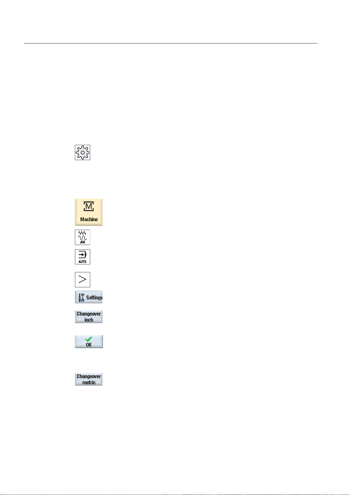
Setting up the machine
2.4 Settings for the machine
2.4.2 Switching the unit of measurement
You can set millimeters or inches as the unit of measurement. Switching the unit of
measurement always applies to the entire machine. All required information is automatically
converted to the new unit of measurement, for example:
● Positions
● Tool offsets
● Work offsets
Machine manufacturer
Please also refer to the machine manufacturer's instructions.
Proceed as follows
1. Select <JOG> or <AUTO> mode in the "Machine" operating area.
2. Press the menu forward key and the "Settings" softkey.
The softkey label changes to "Switch to metric".
A new vertical softkey bar appears.
3. Press the "Switch to inch" softkey.
A prompt asks you whether you really want to switch over the unit of
measurement.
4. Press the "OK" softkey.
The unit of measurement applies to the entire machine.
5. Press the "Switch to metric" softkey to set the unit of measurement of
the machine to metric again.
See also
Default settings for manual mode (Page 121)
Turning
72 Operating Manual, 02/2012, 6FC5398-8CP40-3BA0
Page 73

Setting up the machine
2.4 Settings for the machine
2.4.3 Setting the zero offset
You can enter a new position value in the actual value display for individual axes when a
settable zero offset is active.
The difference between the position value in the machine coordinate system MCS and the
new position value in the workpiece coordinate system WCS is saved permanently in the
currently active zero offset (e.g. G54).
Relative actual value
Further, you also have the possibility of entering position values in the relative coordinate
system.
Note
The new actual value is only displayed. The relative actual value has no effect on the axis
positions and the active zero offset.
Resetting the relative actual value
Press the "Delete REL" softkey.
The actual values are deleted.
The softkeys to set the zero point in the relative coordinate system are only available if the
corresponding machine data is set.
Machine manufacturer
Please refer to the machine manufacturer's specifications.
Requirement
The controller is in the workpiece coordinate system.
The actual value can be set in both the Reset and Stop state.
Note
Setting the ZO in the Stop state
If you enter the new actual value in the Stop state, the changes made are only visible and
only take effect when the program is continued.
Turning
Operating Manual, 02/2012, 6FC5398-8CP40-3BA0
73
Page 74
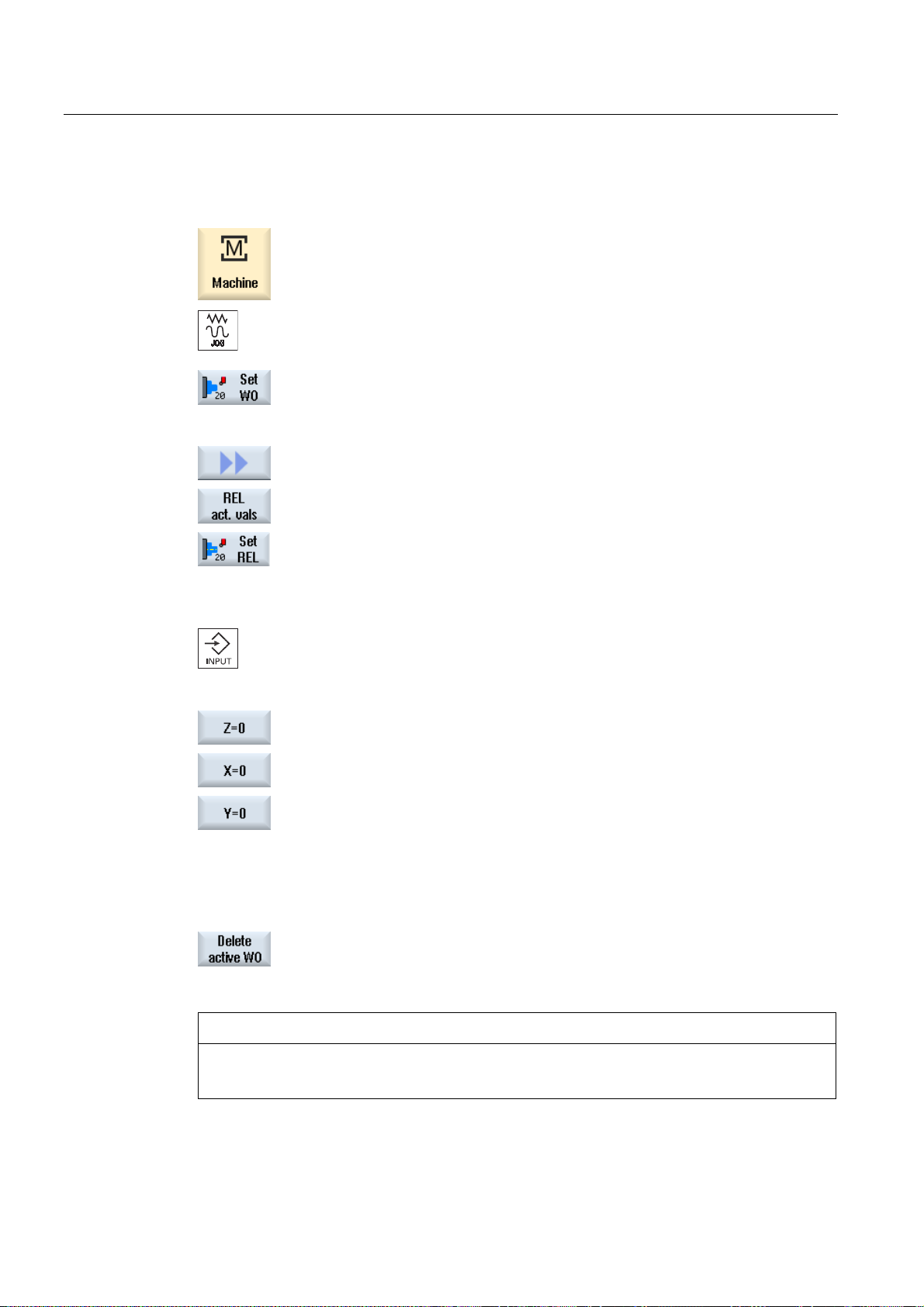
Setting up the machine
2.4 Settings for the machine
Procedure
1. Select the "JOG" mode in the "Machine" operating area.
2. Press the "Set ZO" softkey.
- OR -
Press the ">>", "REL act. vals" and "Set REL" softkeys to set position
values in the relative coordinate system.
- OR -
Resetting the actual value
3. Enter the new required position value for Z, X or Y directly in the actual
value display (you can toggle between the axes with the cursor keys)
and press the <INPUT> key to confirm the entries.
Press softkey "Z=0", "X=0" or "Y=0" (if there is a Y axis), to set the
required position to zero.
Press the "Delete active ZO" softkey.
The offset is deleted permanently.
NOTICE
Irreversible active zero offset
The current active zero offset is irreversibly deleted by this action.
Turning
74 Operating Manual, 02/2012, 6FC5398-8CP40-3BA0
Page 75

Setting up the machine
2.5 Measuring the tool
2.5 Measuring the tool
The geometries of the machining tool must be taken into consideration when executing a
part program. These are stored as tool offset data in the tool list. Each time the tool is called,
the control considers the tool offset data.
When programming the part program, you only need to enter the workpiece dimensions from
the production drawing. After this, the controller independently calculates the individual tool
path.
You can determine the tool offset data, i.e. the length and radius or diameter, either manually
or automatically with tool probes.
See also
Tool dimensioning (Page 643)
Measuring the tool (Page 655)
2.5.1 Measuring a tool manually
When measuring manually, traverse the tool manually to a known reference point in order to
determine the tool dimensions in the X and Z directions. The control system then calculates
the tool offset data from the position of the tool carrier reference point and the reference
point.
Reference point
The workpiece edge is used as the reference point when measuring length X and length Z.
The chuck of the main or counterspindle can also be used when measuring in the Z
direction.
You specify the position of the workpiece edge during the measurement.
Note
Lathes with B axis
For lathes with a B axis, execute the tool change and alignment in the T, S, M window before
performing the measurement.
Turning
Operating Manual, 02/2012, 6FC5398-8CP40-3BA0
75
Page 76
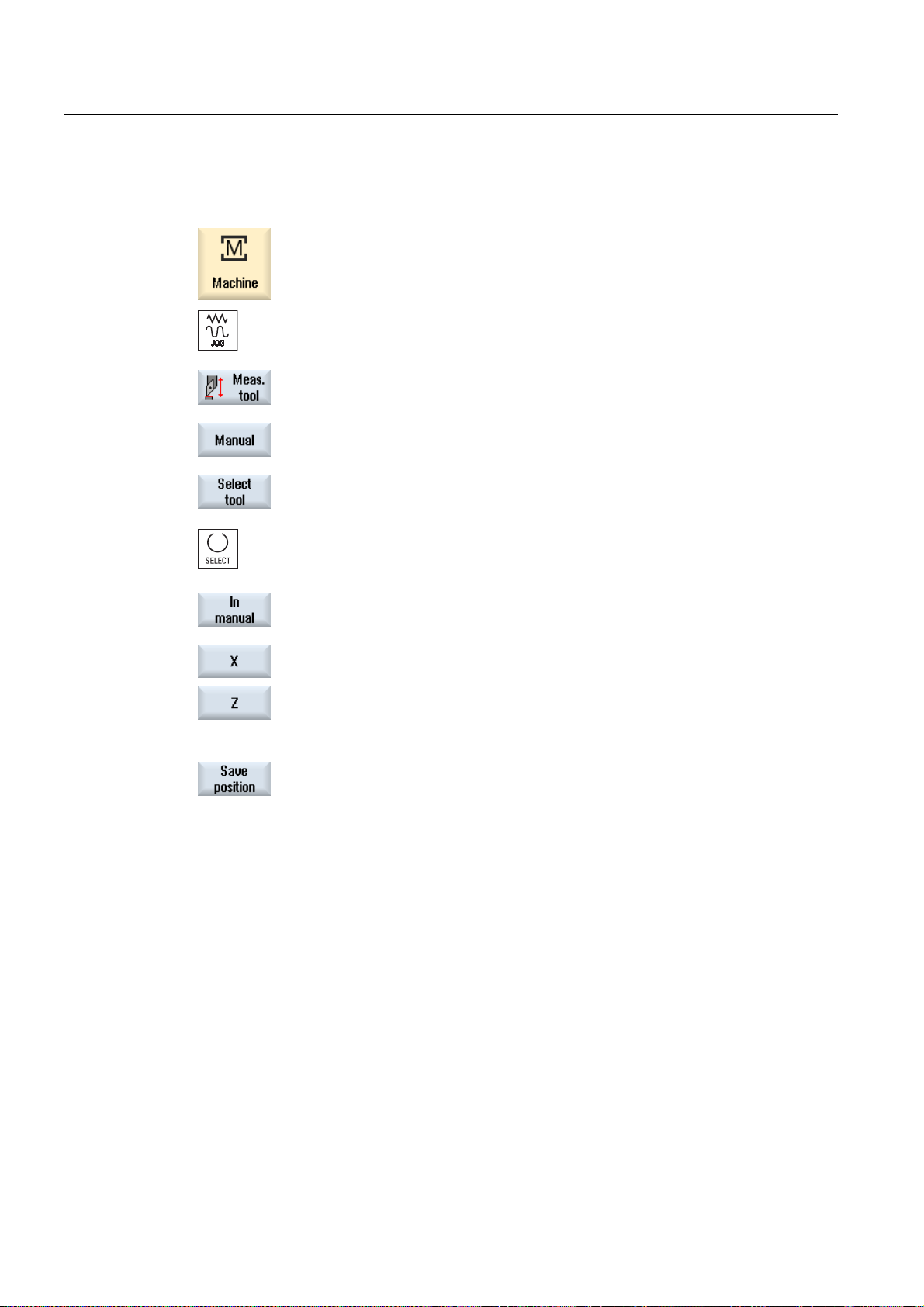
Setting up the machine
2.5 Measuring the tool
Procedure
1. Select "JOG" mode in the "Machine" operating area.
2. Press the "Meas. tool" softkey.
3. Press the "Manual" softkey.
4. Press the "Select tool” softkey.
The "Tool selection" window is opened.
5. Select the tool that you wish to measure.
The cutting edge position and the radius or diameter of the tool must
already be entered in the tool list.
6. Press the "In manual" softkey.
The tool is accepted into the "Length Manual" window.
7. Press the "X" or "Z" softkey, depending on which tool length you want to
measure.
8. Scratch the required edge using the tool.
9. If you do not wish to keep the tool at the workpiece edge, then press the
"Save position" softkey.
The tool position is saved and the tool can be retracted from the
workpiece. For instance, this can be practical if the workpiece diameter
still has to be subsequently measured.
If the tool can remain at the workpiece edge, then after scratching you
can directly continue with step 11.
Turning
76 Operating Manual, 02/2012, 6FC5398-8CP40-3BA0
Page 77

Setting up the machine
2.5 Measuring the tool
10. Enter the position of the workpiece edge in X0 or Z0.
If no value is entered for X0 or Z0, the value is taken from the actual
value display.
11. Press the "Set length" softkey.
The tool length is calculated automatically and entered in the tool list.
Whereby the cutting edge position and tool radius or diameter are
automatically taken into consideration as well.
Note
Tool measurement is only possible with an active tool.
2.5.2 Measuring a tool with a tool probe
During automatic measuring, you determine the tool dimensions in the directions X and Z
with the aid of a probe.
References
You have the possibility of measuring a tool using a tool holder that can be orientated (tool
carrier, swivel).
The function "Measure with tool carrier that can be orientated" is implemented for lathes with
a swivel axis around Y and associated tool spindle. The swivel axis can be used to align the
tool on the X/Z level. The swivel axis can assume any position around Y to measure turning
tools. Multiples of 90° are permitted for milling and drilling tools. Multiples of 180° are
possible when positioning the tool spindle.
Note
Lathes with B axis
For lathes with a B axis, execute the tool change and alignment in the T, S, M window before
performing the measurement.
For further information about lathes with B axis, please refer to the following reference:
Commissioning Manual SINUMERIK Operate / SINUMERIK 840D sl
The tool offset data is then calculated from the known position of the tool carrier reference
point and the probe.
The corresponding windows can be adapted to the measurement tasks in order to
automatically measure tools.
Turning
Operating Manual, 02/2012, 6FC5398-8CP40-3BA0
77
Page 78
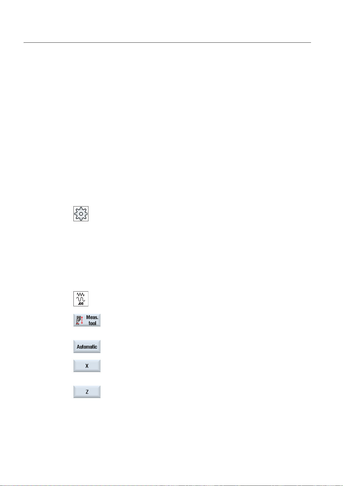
Setting up the machine
2.5 Measuring the tool
Adapting the user interface to calibrating and measuring functions
The following selection options can be switched-in or switched-out:
● Calibration plane, measurement plane
● Probe
● Calibration feedrate (measuring feedrate)
Preconditions
● If you wish to measure your tools with a tool probe, the machine manufacturer must
parameterize special measuring functions for that purpose.
● Enter the cutting edge position and the radius or diameter of the tool in the tool list before
performing the actual measurement. If the tool is measured using a tool carrier that can
be orientated, then the cutting edge position must be entered into the tool list
corresponding to the initial tool carrier position.
● Calibrate the probe first.
Machine manufacturer
Please refer to the machine manufacturer's specifications.
Procedure
1. Insert the tool that you want to measure.
If the tool is to be measured using a tool carrier that can be orientated,
then at this position the tool should be aligned in the same way that it
will be subsequently measured.
2. Select the "JOG" mode in the "Machine" operating area.
3. Press the "Meas. tool" and "Automatic" softkeys.
Press the "X" or "Z" softkey, depending on which tool length you want to
measure.
Turning
78 Operating Manual, 02/2012, 6FC5398-8CP40-3BA0
Page 79

Setting up the machine
2.5 Measuring the tool
4. Manually position the tool in the vicinity of the tool probe in such a way
that any collisions can be avoided when the tool probe is being
traversed in the corresponding direction.
5. Press the <CYCLE START> key.
The automatic measuring process is started, i.e. the tool is traversed at
the measurement feedrate to the probe and back again.
The tool length is calculated and entered in the tool list. Whereby the
cutting edge position and tool radius or diameter are automatically taken
into consideration as well.
If turning tools with tool carrier that can be oriented are measured
around Y using any positions (not multiples of 90°) of the swivel axis,
then it should be taken into consideration that the turning tool is
measured with the same tool position in both axes X/Z, assuming that
this is possible.
2.5.3 Calibrating the tool probe
Sequence
To be able to measure your tools automatically, you must first determine the position of the
tool probe in the machine area in relation to the machine zero.
Machine manufacturer
Please refer to the machine manufacturer's specifications.
The calibrating tool must be a turning tool type (roughing or finishing tool). Cutting edge
positions 1 - 4 can be used for the tool probe calibration. You must enter the length and the
radius or diameter of the calibrating tool in the tool list.
Calibrate the probe in all directions in which you wish to subsequently perform
measurements.
Turning
Operating Manual, 02/2012, 6FC5398-8CP40-3BA0
79
Page 80
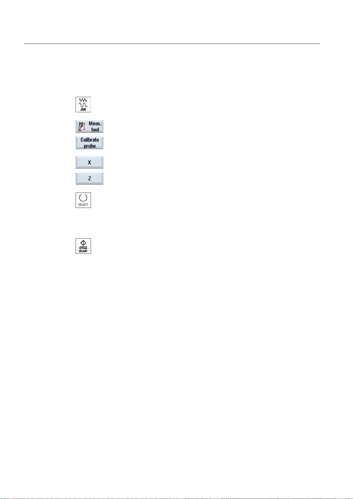
Setting up the machine
2.5 Measuring the tool
Procedure
1. Change the calibrating tool.
2. Select the "JOG" mode in the "Machine" operating area.
3. Press the "Meas. tool" and "Calibrate probe" softkeys.
4. Press the "X" or "Z" softkey, depending on which point of the tool probe
you wish to determine first.
5. Select the direction (+ or -), in which you would like to approach the tool
probe.
6. Position the calibrating tool in the vicinity of the tool probe in such a way
that any collisions can be avoided when the first point of the tool probe
is being approached.
7. Press the <CYCLE START> key.
The calibration process is started, i.e. the calibrating tool is
automatically traversed at the measurement feedrate to the probe and
back again. The position of the tool probe is determined and saved in an
internal data area.
8. Repeat the process for the other other points of the tool probe.
Turning
80 Operating Manual, 02/2012, 6FC5398-8CP40-3BA0
Page 81
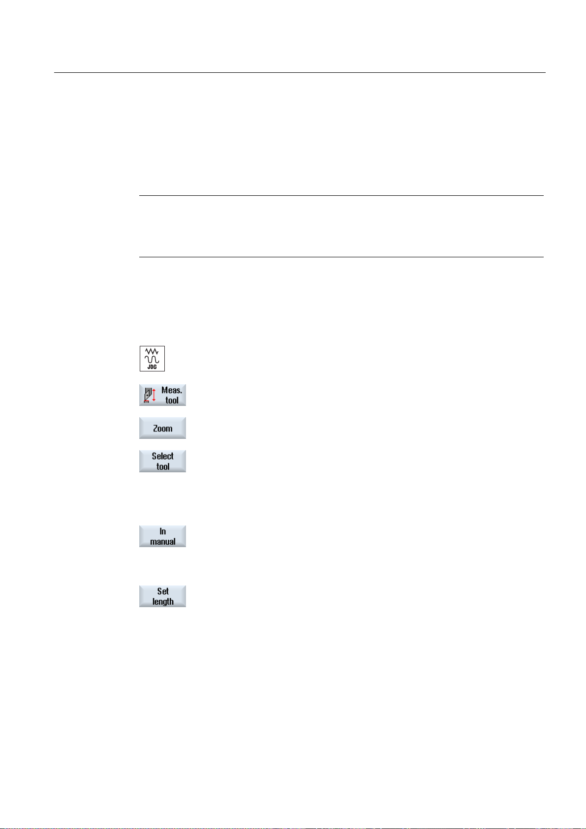
Setting up the machine
2.5 Measuring the tool
2.5.4 Measuring a tool with a magnifying glass
You can also use a magnifying glass to determine the tool dimensions, if this is available on
the machine.
In this case, SINUMERIK Operate calculates the tool offset data from the known positions of
the tool carrier reference point and the cross-hairs of the magnifying glass.
Procedure
Note
Lathes with B axis
For lathes with a B axis, execute the tool change and alignment in the T, S, M window before
performing the measurement.
1. Select the "JOG" mode in the "Machine" operating area.
2. Press the "Meas. tool" softkey.
3. Press the "Zoom" softkey.
4. Press the "Select tool” softkey.
The "Tool selection" window is opened.
5. Select the tool that you wish to measure.
The cutting edge position and the radius or diameter of the tool must
already be entered in the tool list.
6. Press the "In manual" softkey.
The tool is accepted in the "Zoom" window.
7. Traverse the tool towards the magnifying glass and align the tool tip P
with the magnifying glass cross-hairs.
Press the "Set length" softkey.
Turning
Operating Manual, 02/2012, 6FC5398-8CP40-3BA0
81
Page 82

Setting up the machine
2.6 Measuring the workpiece zero
2.6 Measuring the workpiece zero
The reference point for programming a workpiece is always the workpiece zero. To
determine this zero point, measure the length of the workpiece and save the position of the
cylinder's face surface in the direction Z in a zero offset. This means that the position is
stored in the coarse offset and existing values in the fine offset are deleted.
Calculation
When the workpiece zero / zero offset is calculated, the tool length is automatically taken
into account.
Measuring only
If you wish to measure the workpiece zero in "Measuring Only" mode, the measured values
are merely displayed without any changes being made to the coordinate system.
Adapting the user interface to the measurement functions
The following selection options can be switched-in or switched-out:
Requirement
● Calibration plane, measuring plane (only 840D sl)
● Zero offset as basis for the measuring process (only 840D sl)
● Number of the probe calibration data record (only 840D sl)
● Offset target, settable zero offset
● Offset target, basis reference
● Offset target, global basic zero offset (only 840D sl)
● Offset target, channel-specific basic zero offset (only 840D sl)
Machine manufacturer
Please refer to the machine manufacturer's specifications.
The requirement for measuring the workpiece is that a tool with known lengths is in the
machining position.
Turning
82 Operating Manual, 02/2012, 6FC5398-8CP40-3BA0
Page 83
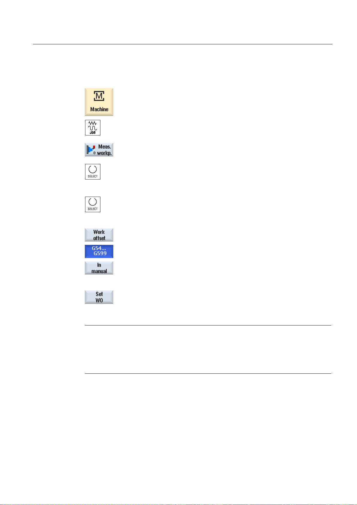
Setting up the machine
2.6 Measuring the workpiece zero
Procedure
1. Select "JOG" mode in the "Machine" operating area.
2. Press the "Workpiece zero" softkey.
- OR -
The "Set Edge" window opens.
3. Select "Measuring only" if you only want to display the measured
values.
Select the desired zero offset in which you want to store the zero point
(e.g. basis reference).
- OR -
Press the "Zero offset" softkey and select the zero offset in which the
zero point is to be saved in the "Zero Offset – G54 … G599" window
that opens and press the "In Manual" softkey.
You return to the "Set Edge" window.
4. Traverse the tool in the Z direction and scratch the workpiece.
5. Enter the position setpoint of the workpiece edge Z0 and press the "Set
ZO" softkey.
Note
Settable zero offsets
The labeling of the softkeys for the settable zero offsets varies, i.e. the settable zero offsets
configured on the machine are displayed (examples: G54…G57, G54…G505, G54…G599).
Please refer to the machine manufacturer's specifications.
Turning
Operating Manual, 02/2012, 6FC5398-8CP40-3BA0
83
Page 84
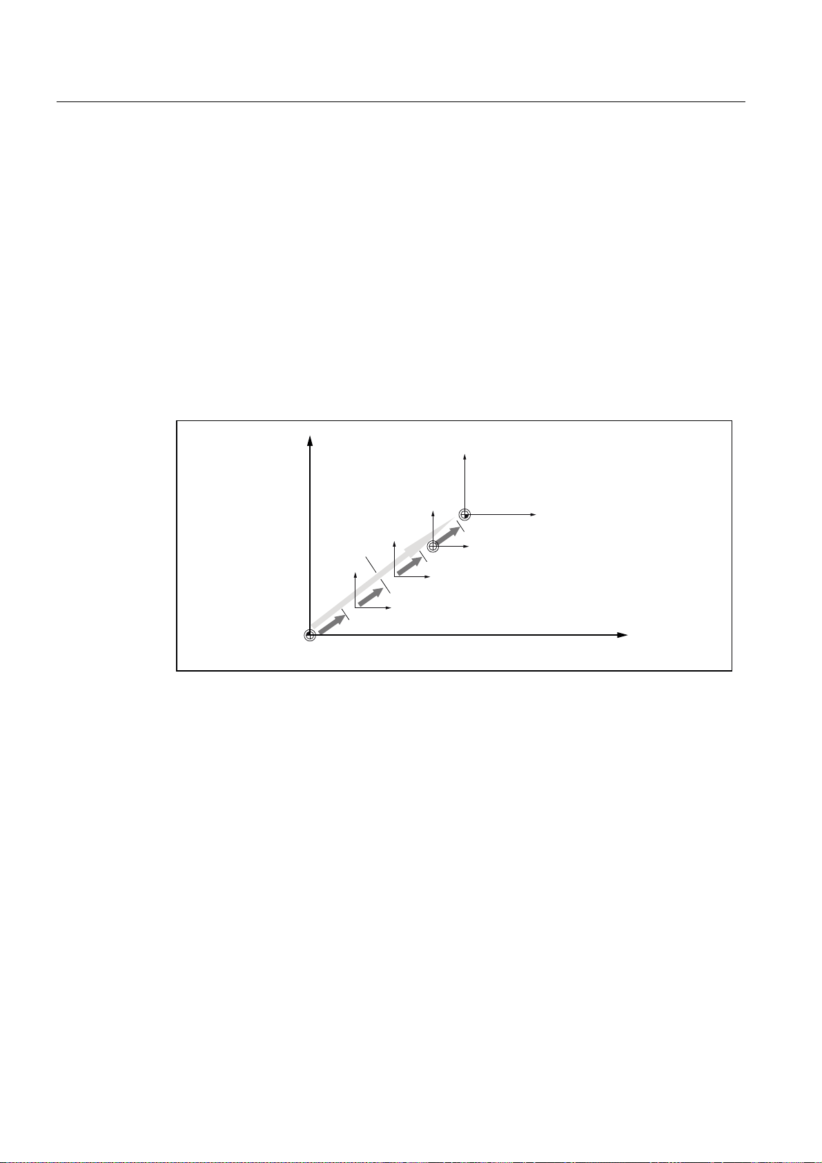
Setting up the machine
2.7 Zero offsets
2.7 Zero offsets
Following reference point approach, the actual value display for the axis coordinates is
based on the machine zero (M) of the machine coordinate system (Machine). The program
for machining the workpiece, however, is based on the workpiece zero (W) of the workpiece
coordinate system (Work). The machine zero and workpiece zero are not necessarily
identical. The distance between the machine zero and the workpiece zero depends on the
workpiece type and how it is clamped. This zero offset is taken into account during execution
of the program and can be a combination of different offsets.
Following reference point approach, the actual value display for the axis coordinates is
based on the machine zero of the machine coordinate system (Machine).
The actual value display of the positions can also refer to the SZS coordinate system
(settable zero system). The position of the active tool relative to the workpiece zero is
displayed.
:
:&6
&RRUGLQDWHWUDQVIRUPDWLRQ
0
7RW D O
RIIVHW
:RUNRIIVHWI LQH
:RUNRIIVHWFRDUVH
%DVLFRIIVHW
6=6
0&6
Figure 2-1 Zero offsets
When the machine zero is not identical to the workpiece zero, at least one offset (base offset
or zero offset) exists in which the position of the workpiece zero is saved.
Base offset
The base offset is a zero offset that is always active. If you have not defined a base offset, its
value will be zero. The base offset is specified in the "Zero Offset - Base" window.
Turning
84 Operating Manual, 02/2012, 6FC5398-8CP40-3BA0
Page 85

Setting up the machine
2.7 Zero offsets
Coarse and fine offsets
Every zero offset (G54 to G57, G505 to G599) consists of a coarse offset and a fine offset.
You can call the zero offsets from any program (coarse and fine offsets are added together).
You can save the workpiece zero, for example, in the coarse offset, and then store the offset
that occurs when a new workpiece is clamped between the old and the new workpiece zero
in the fine offset.
Note
Deselect fine offset
You have the option of deselecting the fine offset via machine data
$MN_MM_FRAM_FINE_TRANS
See also
Actual value window (Page 44)
Turning
Operating Manual, 02/2012, 6FC5398-8CP40-3BA0
85
Page 86

Setting up the machine
2.7 Zero offsets
2.7.1 Display active zero offset
The following zero offsets are displayed in the "Zero Offset - Active" window:
● Zero offsets, for which active offsets are included, or for which values are entered.
● Settable zero offsets
● Total zero offset
This window is generally used only for monitoring.
The availability of the offsets depends on the setting.
Machine manufacturer
Please refer to the machine manufacturer's specifications.
Procedure
1. Select the "Parameter" operating area.
2. Press the "Zero offset" softkey.
The "Zero Offset - Active" window is opened.
Note
Further details on zero offsets
If you would like to see further details about the specified offsets or if you would like to
change values for the rotation, scaling or mirroring, press the "Details" softkey.
Turning
86 Operating Manual, 02/2012, 6FC5398-8CP40-3BA0
Page 87

Setting up the machine
2.7 Zero offsets
2.7.2 Displaying the zero offset "overview"
The active offsets or system offsets are displayed for all set-up axes in the "Zero Offset Overview" window.
In addition to the offset (course and fine), the rotation, scaling and mirroring defined using
this are also displayed.
This window is generally used only for monitoring.
Display of active zero offsets
Zero offsets
DRF Displays the handwheel axis offset.
Rotary table reference Displays the additional zero offsets programmed with $
P_PARTFRAME.
Basic reference Displays the additional zero offsets programmed with $P_SETFRAME.
Access to the system offsets is protected via a keyswitch.
External ZO frame Displays the additional zero offsets programmed with $P_EXTFRAME.
Total base ZO Displays all effective basis offsets.
G500 Displays the zero offsets activated with G54 - G599.
Under certain circumstances, you can change the data using "Set ZO",
i.e. you can correct a zero point that has been set.
Tool reference Displays the additional zero offsets programmed with
$P_TOOLFRAME.
Workpiece reference Displays the additional zero offsets programmed with $P_WPFRAME.
Programmed ZO Displays the additional zero offsets programmed with $P_PFRAME.
Cycle reference Displays the additional zero offsets programmed with $P_CYCFRAME.
Total ZO Displays the active zero offset, resulting from the total of all zero
offsets.
Procedure
1. Select the "Parameter" operating area.
Turning
Operating Manual, 02/2012, 6FC5398-8CP40-3BA0
2 Press the "Zero offset" and "Overview" softkeys.
The "Zero Offsets - Overview" window opens.
87
Page 88
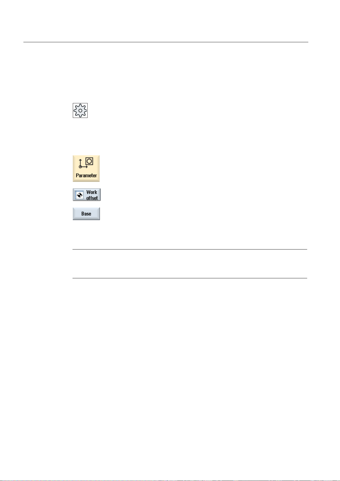
Setting up the machine
2.7 Zero offsets
2.7.3 Displaying and editing base zero offset
The defined channel-specific and global base offsets, divided into coarse and fine offsets,
are displayed for all set-up axes in the "Zero offset - Base" window.
Machine manufacturer
Please refer to the machine manufacturer's specifications.
Procedure
1. Select the "Parameter" operating area.
2. Press the "Zero offset" softkey.
3. Press the "Base" softkey.
The "Zero Offset - Base" window is opened.
4. You can edit the values directly in the table.
Note
Activate base offsets
The offsets specified here are immediately active.
Turning
88 Operating Manual, 02/2012, 6FC5398-8CP40-3BA0
Page 89
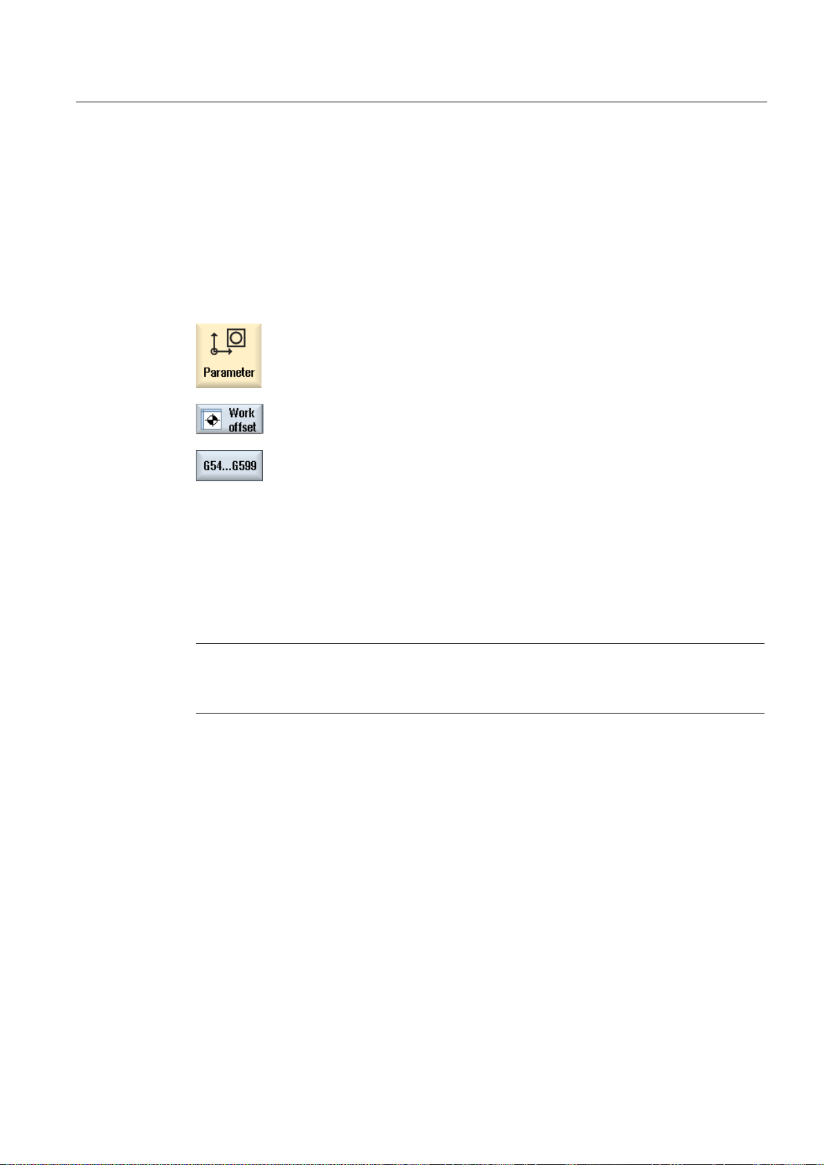
Setting up the machine
2.7 Zero offsets
2.7.4 Displaying and editing settable zero offset
All settable offsets, divided into coarse and fine offsets, are displayed in the "Zero Offset G54..G599" window.
Rotation, scaling and mirroring are displayed.
Procedure
1. Select the "Parameter" operating area.
2. Press the "Zero offset" softkey.
4. You can edit the values directly in the table.
3. Press the "G54…G599" softkey.
The "Zero Offset - G54..G599" window is opened.
Note
The labeling of the softkeys for the settable zero offsets varies, i.e. the
settable zero offsets configured on the machine are displayed
(examples: G54…G57, G54…G505, G54…G599).
Please observe the machine manufacturer's specifications.
Note
Activate settable zero offsets
The settable zero offsets must first be selected in the program before they have an impact.
Turning
Operating Manual, 02/2012, 6FC5398-8CP40-3BA0
89
Page 90
Setting up the machine
2.7 Zero offsets
2.7.5 Displaying and editing details of the zero offsets
For each zero offset, you can display and edit all data for all axes. You can also delete zero
offsets.
For every axis, values for the following data will be displayed:
● Coarse and fine offsets
● Rotation
● Scaling
● Mirroring
Machine manufacturer
Please refer to the machine manufacturer's specifications.
Note
Procedure
Settings for rotation, scaling and mirroring are specified here and can only be changed here.
1. Select the "Parameter" operating area.
2. Press the "Zero offset" softkey.
3. Press the "Active", "Base" or "G54…G599" softkey.
The corresponding window appears.
4. Place the cursor on the desired zero offset to view its details.
5. Press the "Details" softkey.
A window opens, depending on the selected zero offset, e.g. "Zero
Offset - Details: G54 to G599".
6. You can edit the values directly in the table.
- OR -
Press the "Clear offset" softkey to reset all entered values.
Turning
90 Operating Manual, 02/2012, 6FC5398-8CP40-3BA0
Page 91

Setting up the machine
2.7 Zero offsets
Press the "ZO +" or "ZO -" softkey to select the next or previous offset,
...
respectively, within the selected area ("Active", "Base", "G54 to G599")
without first having to switch to the overview window.
If you have reached the end of the range (e.g. G599), you will switch
automatically to the beginning of the range (e.g. G54).
These value changes are available in the part program immediately or after "Reset".
Machine manufacturer
Please refer to the machine manufacturer's specifications.
Press the "Back" softkey to close the window.
Turning
Operating Manual, 02/2012, 6FC5398-8CP40-3BA0
91
Page 92
Setting up the machine
2.7 Zero offsets
2.7.6 Deleting a zero offset
You have the option of deleting zero offsets. This resets the entered values.
Procedure
1. Select the "Parameter" operating area.
2. Press the "Zero offset" softkey.
3. Press the "Active", "Base" or "G54…G599" softkey.
4. Press the "Details" softkey.
5. Position the cursor on the zero offset you would like to delete.
6. Press the "Clear offset" softkey.
Turning
92 Operating Manual, 02/2012, 6FC5398-8CP40-3BA0
Page 93
Setting up the machine
2.7 Zero offsets
2.7.7 Measuring the workpiece zero
Procedure
1. Select the "Parameters" operating area and press the "Zero offset"
softkey.
2. Press the "G54...G599" softkey and select the zero offset in which the
zero point is to be saved.
3. Press the "Workpiece zero" softkey.
You change to the "Set Edge" window in the "JOG" mode.
4. Traverse the tool in the Z direction and scratch it.
5. Enter the position setpoint of the workpiece edge Z0 and press the "Set
ZO" softkey.
Turning
Operating Manual, 02/2012, 6FC5398-8CP40-3BA0
93
Page 94

Setting up the machine
2.8 Monitoring axis and spindle data
2.8 Monitoring axis and spindle data
2.8.1 Specify working area limitations
The "Working area limitation" function can be used to limit the range within which a tool can
traverse in all channel axes. These commands allow you to set up protection zones in the
working area which are out of bounds for tool movements.
In this way, you are able to restrict the traversing range of the axes in addition to the limit
switches.
Requirements
You can only make changes in "AUTO" mode when in the RESET condition. These changes
are then immediate.
You can make changes in "JOG" mode at any time. These changes, however, only become
active at the start of a new motion.
Procedure
1. Select the "Parameter" operating area.
2. Press the "Setting data" softkey.
The "Working Area Limitation" window appears.
3. Place the cursor in the required field and enter the new values via the
numeric keyboard.
The upper or lower limit of the protection zone changes according to
your inputs.
4. Click the "active" checkbox to activate the protection zone.
Note
You will find all of the setting data in the "Start-up" operating area under "Machine data" via
the menu forward key.
Turning
94 Operating Manual, 02/2012, 6FC5398-8CP40-3BA0
Page 95

Setting up the machine
2.8 Monitoring axis and spindle data
2.8.2 Editing spindle data
The speed limits set for the spindles that must not be under- or overshot are displayed in the
"Spindles" window.
You can limit the spindle speeds in fields "Minimum" and "Maximum" within the limit values
defined in the relevant machine data.
Spindle speed limitation at constant cutting rate
In field "Spindle speed limitation at G96", the programmed spindle speed limitation at
constant cutting speed is displayed together with the permanently active limitations.
This speed limitation, for example, prevents the spindle from accelerating to the max. spindle
speed of the current gear stage (G96) when performing tapping operations or machining
very small diameters.
Note
The "Spindle data" softkey only appears if a spindle is configured.
Procedure
1. Select the "Parameter" operating area.
2. Press the "Setting data" and "Spindle data" softkeys.
The "Spindles" window opens.
3. If you want to change the spindle speed, place the cursor on the
"Maximum", "Minimum", or "Spindle speed limitation at G96" and enter a
new value.
Turning
Operating Manual, 02/2012, 6FC5398-8CP40-3BA0
95
Page 96
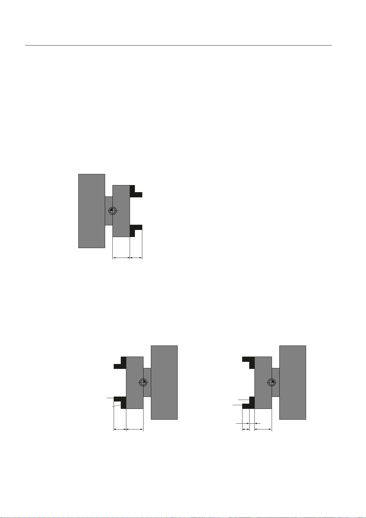
Setting up the machine
2.8 Monitoring axis and spindle data
2.8.3 Spindle chuck data
You store the chuck dimensions of the spindles at your machine in the "Spindle chuck data"
window.
Manually measuring a tool
If you want to use the chuck of the main or counter spindle as a reference point during
manual measuring, specify the chuck dimension ZC.
Main spindle
Counterspindle
=& =6
Dimensioning the main spindle
You can measure either the forward edge or stop edge of the counter-spindle. The forward
edge or stop edge automatically serves as the valid reference point when traversing the
counter-spindle. This is especially important when gripping the workpiece using the counterspindle.
)URQWHGJH
6WRSHGJH
=&
=6
Dimensions, counterspindle jaw type 1
6WRSHGJH
)URQWHGJH
=6
=&
=(
Dimensions, counterspindle jaw type 2
Turning
96 Operating Manual, 02/2012, 6FC5398-8CP40-3BA0
Page 97

Setting up the machine
2.8 Monitoring axis and spindle data
Tailstock
;5
Procedure
=5
Dimensioning the tailstock
The length of the tailstock (ZR) and the diameter of the tailstock (XR) of the spindle screen
are needed for the display of the tailstock in the simulation.
1. Select the "Parameter" operating area.
2. Press softkeys "Setting data" and "Spindle chuck data".
The "Spindle chuck data" window opens.
3. Enter the desired parameters.
The settings become active immediately.
See also
Machining with the counterspindle (Page 521)
Turning
Operating Manual, 02/2012, 6FC5398-8CP40-3BA0
97
Page 98

Setting up the machine
2.8 Monitoring axis and spindle data
Parameter Description Unit
ZC1 Main spindle chuck dimensions (inc) mm
Jaw type Dimensions of the forward edge or stop edge
Jaw type 1
Jaw type 2
ZC3 Chuck dimension, counter-spindle (inc) - only for a counter-spindle that has been
set-up
ZS3 Stop dimension, counter-spindle (inc) - only for a counter-spindle that has been
set-up
ZE3 Jaw dimension, counter-spindle (inc) - only for a counter-spindle that has been
set-up and "Jaw type 1"
XR Tailstock diameter - only for tailstock that has been set-up mm
ZR Tailstock length - only for tailstock that has been set-up mm
mm
mm
mm
Turning
98 Operating Manual, 02/2012, 6FC5398-8CP40-3BA0
Page 99
Setting up the machine
2.9 Displaying setting data lists
2.9 Displaying setting data lists
You can display lists with configured setting data.
Machine manufacturer
Please refer to the machine manufacturer's specifications.
Procedure
1. Select the "Parameter" operating area.
2. Press the "Setting data" and "Data lists" softkeys.
The "Setting Data Lists" window opens.
3. Press the "Select data list" softkey and in the "View" list, select the
required list with setting data.
Turning
Operating Manual, 02/2012, 6FC5398-8CP40-3BA0
99
Page 100
Setting up the machine
2.10 Handwheel assignment
2.10 Handwheel assignment
You can traverse the axes in the machine coordinate system (Machine) or in the workpiece
coordinate system (Work) via the handwheel.
Software option
All axes are provided in the following order for handwheel assignment:
● Geometry axes
When traversing, the geometry axes taken into account the actual machine status (e.g.
rotations, transformations). All channel machine axes, which are currently assigned to the
geometry axis, are in this case simultaneously traversed.
● Channel machine axes
Channel machine axes are assigned to the particular channel. They can only be
individually traversed, i.e. the actual machine state has no influence.
You require the "Extended operator functions" option for the handwheel offset
(only for 828D).
Procedure
The also applies to channel machine axes, that are declared as geometry axes.
Machine manufacturer
Please refer to the machine manufacturer's specifications.
1. Select the "Machine" operating area.
Press the <JOG>, <AUTO> or <MDI> key.
2. Press the menu forward key and the "Handwheel" softkey.
The "Handwheel" window appears.
A field for axis assignment will be offered for every connected
handwheel.
3. Position the cursor in the field next to the handwheel with which you
wish to assign the axis (e.g. No. 1).
Turning
100 Operating Manual, 02/2012, 6FC5398-8CP40-3BA0
 Loading...