

Page 1

SINUMERIK
SINUMERIK 840D sl / 828D
Ctrl-Energy
Valid for
Control system
SINUMERIK 840D sl / 840DE sl / 828D
Software Version
CNC Software 4.7 SP1
Preface
Fundamental safety
instructions
1
System Manual
Introduction
Ctrl-E Analysis
Ctrl-E Profiles
Reactive power
compensation
Flux reduction
User know-how
Appendix
2
3
4
5
6
7
A
01/2015
6FC5397-0EP40-5BA2
Page 2
Legal information
Warning notice system
This manual contains notices you have to observe in order to ensure your personal safety, as well as to prevent
damage to property. The notices referring to your personal safety are highlighted in the manual by a safety alert
symbol, notices referring only to property damage have no safety alert symbol. These notices shown below are
graded according to the degree of danger.
DANGER
indicates that death or severe personal injury will result if proper precautions are not taken.
WARNING
indicates that death or severe personal injury may result if proper precautions are not taken.
CAUTION
indicates that minor personal injury can result if proper precautions are not taken.
NOTICE
indicates that property damage can result if proper precautions are not taken.
If more than one degree of danger is present, the warning notice representing the highest degree of danger will be
used. A notice warning of injury to persons with a safety alert symbol may also include a warning relating to property
damage.
Qualified Personnel
The product/system described in this documentation may be operated only by personnel qualified for the specific
task in accordance with the relevant documentation, in particular its warning notices and safety instructions. Qualified
personnel are those who, based on their training and experience, are capable of identifying risks and avoiding
potential hazards when working with these products/systems.
Proper use of Siemens products
Note the following:
WARNING
Siemens products may only be used for the applications described in the catalog and in the relevant technical
documentation. If products and components from other manufacturers are used, these must be recommended or
approved by Siemens. Proper transport, storage, installation, assembly, commissioning, operation and
maintenance are required to ensure that the products operate safely and without any problems. The permissible
ambient conditions must be complied with. The information in the relevant documentation must be observed.
Trademarks
All names identified by ® are registered trademarks of Siemens AG. The remaining trademarks in this publication
may be trademarks whose use by third parties for their own purposes could violate the rights of the owner.
Disclaimer of Liability
We have reviewed the contents of this publication to ensure consistency with the hardware and software described.
Since variance cannot be precluded entirely, we cannot guarantee full consistency. However, the information in
this publication is reviewed regularly and any necessary corrections are included in subsequent editions.
Siemens AG
Division Digital Factory
Postfach 48 48
90026 NÜRNBERG
GERMANY
Order number: 6FC5397-0EP40-5BA2
Ⓟ 07/2015 Subject to change
Copyright © Siemens AG 2011 - 2015.
All rights reserved
Page 3

Preface
SINUMERIK documentation
SINUMERIK documentation
The SINUMERIK documentation is organized in the following categories:
● General documentation
● User documentation
● Manufacturer/service documentation
Additional information
You can find information on the following topics at www.siemens.com/motioncontrol/docu:
● Ordering documentation/overview of documentation
● Additional links to download documents
● Using documentation online (find and search in manuals/information)
Please send any questions about the technical documentation (e.g. suggestions for
improvement, corrections) to the following address:
My Documentation Manager (MDM)
Under the following link you will find information to individually compile OEM-specific machine
documentation based on the Siemens content:
www.siemens.com/mdm
Training
For information about the range of training courses, refer under:
● www.siemens.com/sitrain
SITRAIN - Siemens training for products, systems and solutions in automation technology
● www.siemens.com/sinutrain
SinuTrain - training software for SINUMERIK
FAQs
You can find Frequently Asked Questions in the Service&Support pages under Product
Support. http://support.automation.siemens.com
Ctrl-Energy
System Manual, 01/2015, 6FC5397-0EP40-5BA2 3
Page 4

Preface
SINUMERIK
You can find information on SINUMERIK under the following link:
www.siemens.com/sinumerik
Hotline and Internet address
Technical Support
You will find telephone numbers for other countries for technical support in the Internet under
http://www.siemens.com/automation/service&support
EC Declaration of Conformity
The EC Declaration of Conformity for the EMC Directive can be found on the Internet at:
http://support.automation.siemens.com/WW/view/de/10805517/134200
Ctrl-Energy
4 System Manual, 01/2015, 6FC5397-0EP40-5BA2
Page 5

Table of contents
Preface.........................................................................................................................................................3
1 Fundamental safety instructions...................................................................................................................7
1.1 General safety instructions.......................................................................................................7
1.2 Industrial security.....................................................................................................................7
2 Introduction...................................................................................................................................................9
3 Ctrl-E Analysis............................................................................................................................................11
3.1 SENTRON PAC3200/4200....................................................................................................12
3.1.1 Hardware................................................................................................................................12
3.1.2 Commissioning the Power Monitoring Device........................................................................13
3.1.3 Commissioning the PAC PROFIBUS expansion module (840D sl).......................................14
3.1.4 Commissioning the expansion module PAC PROFINET (828D)...........................................15
3.2 Commissioning the PLC for SENTRON PAC........................................................................15
3.2.1 SINUMERIK 840D sl..............................................................................................................15
3.2.1.1 Commissioning the PLC with PROFIBUS..............................................................................15
3.2.1.2 Commissioning the PLC with PROFINET..............................................................................19
3.2.2 SINUMERIK 828D..................................................................................................................22
3.3 Commissioning the PLC for Ctrl-E Analysis...........................................................................23
3.3.1 Configuring the energy consumption display for SINUMERIK 840D sl..................................23
3.3.1.1 PLC user program for SINUMERIK 840D sl programming....................................................27
3.3.2 Configuring the display of energy consumption for SINUMERIK 828D.................................29
3.3.2.1 Programming the PLC user program for SINUMERIK 828D.................................................33
3.4 Commissioning the HMI for Ctrl-E Analysis...........................................................................37
3.4.1 Changing display texts of the auxiliary systems.....................................................................37
3.5 Long time measurement.......................................................................................................38
3.6 Power display in the status line of the "Machine" operating area..........................................38
4 Ctrl-E Profiles.............................................................................................................................................39
4.1 Commissioning the PLC for Ctrl-E Profiles............................................................................39
4.1.1 Overview................................................................................................................................39
4.1.2 Automatic state machine PLC functions................................................................................40
4.1.3 Checking the energy-saving states........................................................................................42
4.1.4 PLC user program..................................................................................................................43
4.1.5 Interface signals 840D sl........................................................................................................44
4.1.5.1 Signals for controlling energy-saving profiles.........................................................................44
4.1.5.2 Signals for parameterization..................................................................................................45
4.1.6 Interface signals 828D...........................................................................................................46
4.1.6.1 Signals for controlling energy-saving profiles.........................................................................46
4.1.6.2 Signals for parameterization..................................................................................................47
4.2 Creating and editing energy-saving profiles...........................................................................48
Ctrl-Energy
System Manual, 01/2015, 6FC5397-0EP40-5BA2 5
Page 6

Table of contents
5 Reactive power compensation...................................................................................................................53
6 Flux reduction.............................................................................................................................................55
7 User know-how...........................................................................................................................................57
7.1 Commissioning user screen forms.........................................................................................57
A Appendix.....................................................................................................................................................59
A.1 Overview................................................................................................................................59
Index...........................................................................................................................................................61
Ctrl-Energy
6 System Manual, 01/2015, 6FC5397-0EP40-5BA2
Page 7
Fundamental safety instructions
1.1 General safety instructions
WARNING
Risk of death if the safety instructions and remaining risks are not carefully observed
If the safety instructions and residual risks are not observed in the associated hardware
documentation, accidents involving severe injuries or death can occur.
● Observe the safety instructions given in the hardware documentation.
● Consider the residual risks for the risk evaluation.
WARNING
Danger to life or malfunctions of the machine as a result of incorrect or changed
parameterization
As a result of incorrect or changed parameterization, machines can malfunction, which in turn
can lead to injuries or death.
● Protect the parameterization (parameter assignments) against unauthorized access.
● Respond to possible malfunctions by applying suitable measures (e.g. EMERGENCY
STOP or EMERGENCY OFF).
1
1.2 Industrial security
Note
Industrial security
Siemens provides products and solutions with industrial security functions that support the
secure operation of plants, solutions, machines, equipment and/or networks. They are
important components in a holistic industrial security concept. With this in mind, Siemens’
products and solutions undergo continuous development. Siemens recommends strongly that
you regularly check for product updates.
For the secure operation of Siemens products and solutions, it is necessary to take suitable
preventive action (e.g. cell protection concept) and integrate each component into a holistic,
state-of-the-art industrial security concept. Third-party products that may be in use should also
be considered. For more information about industrial security, visit this address (http://
www.siemens.com/industrialsecurity).
To stay informed about product updates as they occur, sign up for a product-specific
newsletter. For more information, visit this address (http://support.automation.siemens.com).
Ctrl-Energy
System Manual, 01/2015, 6FC5397-0EP40-5BA2 7
Page 8

Fundamental safety instructions
1.2 Industrial security
WARNING
Danger as a result of unsafe operating states resulting from software manipulation
Software manipulation (e.g. by viruses, Trojan horses, malware, worms) can cause unsafe
operating states to develop in your installation which can result in death, severe injuries and/
or material damage.
● Keep the software up to date.
You will find relevant information and newsletters at this address (http://
support.automation.siemens.com).
● Incorporate the automation and drive components into a holistic, state-of-the-art industrial
security concept for the installation or machine.
You will find further information at this address (http://www.siemens.com/
industrialsecurity).
● Make sure that you include all installed products into the holistic industrial security concept.
Ctrl-Energy
8 System Manual, 01/2015, 6FC5397-0EP40-5BA2
Page 9

Introduction
The topics of energy efficiency and energy saving are also playing an increasingly important
role in the machine tool environment.
With SINUMERIK Ctrl-Energy, Siemens is offering an extensive range of components,
functions, software tools and services to increase the efficiency of machine tools.
Ctrl-Energy
You will find an overview of the complete range of functions under the following link:
www.siemens.com/sinumerik/ctrl-energy
Acquisition, evaluation, and control of energy consumption
The functions Ctrl-E Analysis to acquire and evaluate the energy consumption of the machine
and Ctrl-E Profiles, to control energy-saving states of the machine are available in SINUMERIK
Operate. Additional energy-saving functions or user know-how on this topic can be added in
this area of SINUMERIK Operate.
2
Ctrl-Energy
System Manual, 01/2015, 6FC5397-0EP40-5BA2 9
Page 10

Introduction
Ctrl-Energy
10 System Manual, 01/2015, 6FC5397-0EP40-5BA2
Page 11

Ctrl-E Analysis
In order to sensitize users to the topic of energy efficiency, the power and energy data of the
machine are first acquired.
Acquiring and evaluating energy consumption
A control system with SINUMERIK Operate without a connected measuring instrument
determines the power directly from the drives and displays this.
Additional consumption-relevant data can be retrieved and displayed at the control using the
additional SENTRON PAC Power Monitoring Device.
Depending on where the SENTRON PAC measuring transducer is installed, you have the
possibility of either measuring the power of the whole machine or only a specific load.
With an integrated measuring function, the energy consumption during a measuring period
can be acquired for all drives together with an additional measuring location – and the electrical
power drawn for a selected load can be recorded with respect to time.
Display of energy consumption
● The user can see a graphic of the current power consumption in the first status line of the
"Machine" operating area.
3
● Additionally, in the Ctrl-Energy initial display the user is shown the consumption in the form
of colored bars, which indicate the current power and the results of today's and yesterday's
long time measurement.
Maximum measuring time
The maximum measuring time for energy between start and stop as well as for an NC part
program is, as a result of the trace recording, 922 seconds (00:15:22).
Ctrl-Energy
System Manual, 01/2015, 6FC5397-0EP40-5BA2 11
Page 12

Ctrl-E Analysis
3.1 SENTRON PAC3200/4200
3.1 SENTRON PAC3200/4200
3.1.1 Hardware
Hardware components
You require the following hardware in order to be able to use all of the "Ctrl-Energy" functions:
● SENTRON PAC3200 (Firmware ≥ V2.2.0)
http://support.automation.siemens.com/WW/view/de/25240652/130000
● SENTRON PAC4200 (Firmware ≥ V1.4.0)
http://support.automation.siemens.com/WW/view/de/31675630/130000
● SENTRON PAC - accessories
http://www.automation.siemens.com/btlv-static/
Lowvoltage_LV10-1_complete_German_2011.pdf
– Power Monitoring Device (page 11/27 ff)
– Current transformer (Page 11/39)
● The expansion modules must be temporarily removed in order to upgrade the firmware
using powerconfig.
● Protection/fusing of the supply and measuring voltages according to Configuration Manual
● Expansion module PAC PROFINET; order number 7KM 9300-0AE01-0AA0
● Expansion module PAC PROFIBUS; order number 7KM 9300-0AB01-0AA0
● PC software powerconfig (≥ V2.2)
http://support.automation.siemens.com/WW/view/de/50246395
● Current transformer depending on
– the connection type at the SENTRON PAC
– Accuracy requirements
– Currents
DANGER
Open current transformer circuits result in electric shock and arcing
If not observed, will cause death, serious injury or considerable property damage.
Only measure the current using external current transformers. DO NOT protect the
circuits using a fuse. Do not open the secondary circuit of the current transformer under
load. Short circuit the secondary current terminals of the current transformer before
removing this device. The safety information for the current transformers used must
be carefully followed.
Selection example
Catalog, Siemens LV 1/Accessories and spare parts:
Ctrl-Energy
12 System Manual, 01/2015, 6FC5397-0EP40-5BA2
Page 13

References
Ctrl-E Analysis
3.1 SENTRON PAC3200/4200
For a three-phase measurement according to connection type 3P4W (four conductors,
unbalanced load, without voltage transformers, with three current transformers), accuracy
class 1, primary rated current 100 A, secondary rated current 1A, three window-type
transformers are recommended (4NC5117-0CC20).
Note
When measuring the complete machine, it is recommended that the current is sensed directly
after the main switch. For the voltage tap, please observe the usual protection/fusing.
Information on the installation, configuration and operation of the Power Monitoring Device
and the expansion module can be found in the following references:
● SENTRON PAC3200 Power Monitoring Device Manual
(Document order number A5E01168664A-05)
● SENTRON PAC4200 Power Monitoring Device System Manual
(Document order number A5E02316180A-03)
● PAC PROFIBUS DP, SWITCHED ETHERNET PROFINET Expansion Module Manual
(document order number A5E01168846A-06)
3.1.2 Commissioning the Power Monitoring Device
A detailed description of commissioning of the SENTRON PAC Power Monitoring Device is
provided in the corresponding manuals.
Preconditions
● The device has been installed.
● The optional expansion modules have been installed.
● The device has been connected in accordance with the possible connection methods.
● The battery has been inserted into the battery compartment (only for the SENTRON
PAC4200).
General procedure when commissioning the device
● Connected the supply voltage
● Parameterizing SENTRON PAC
● Connect the measuring voltage
● Connect the current to be measured
● Check the displayed measured values
● Check the polarity and phase assignment of the measuring transducer
Ctrl-Energy
System Manual, 01/2015, 6FC5397-0EP40-5BA2 13
Page 14

Ctrl-E Analysis
3.1 SENTRON PAC3200/4200
Parameterizing SENTRON PAC
You have the option of parameterizing the measuring device in the following ways:
● Using the input keys and display of the SENTRON PAC
● Using a PC connected to the SENTRON PAC, which has the software this has been
supplied (powerconfig).
After booting select the language and the measuring device is then ready for operation.
3.1.3 Commissioning the PAC PROFIBUS expansion module (840D sl)
To communicate via Profibus, the SENTRON PROFIBUS module in combination with Sentron
PAC3200/4200 must be parameterized differently.
1. Select SENTRON PAC "Settings" > "PROFIBUS modules".
- OR For SENTRON PAC4200, select "Settings" > "Expansion modules" > "MOD1" >
"PROFIBUS MODULE".
2. Press "Enter".
You obtain the following information in the subsequent window:
– Order number
– Serial number of the SENTRON PROFIBUS module
– Firmware version of the SENTRON PROFIBUS module
– PROFIBUS ADDR.:
The DP address of module is displayed here.
3. Press "Enter".
This means that you have the option of entering the same PROFIBUS address as in the
automation system.
Ctrl-Energy
14 System Manual, 01/2015, 6FC5397-0EP40-5BA2
Page 15

3.2 Commissioning the PLC for SENTRON PAC
3.1.4 Commissioning the expansion module PAC PROFINET (828D)
To communicate via PROFINET, the SENTRON SWITCHED ETHERNET PROFINET module
in combination with Sentron PAC3200/4200 must be parameterized differently.
1. Select SENTRON PAC "Settings" > "SWITCHED ETHERNET".
- OR Select SENTRON PAC "Settings" > "Expansion modules" > "MOD1" > "SWITCHED
ETHERNET".
2. Press "ENTER".
You obtain the following information in the subsequent window:
– Order number
– Serial number of the SENTRON SWITCHED ETHERNET PROFINET module
– Firmware version of the SENTRON SWITCHED ETHERNET PROFINET module
– The first character of the NameOfStation of the SENTRON SWITCHED ETHERNET
PROFINET module that can be a maximum of 26 characters
– IP-ADDR.:
The IP address of the module is displayed here.
Ctrl-E Analysis
3. Using the menu item "- ->", open the next window and obtain among other things the
information about the SUBNET address of the module.
Specifying/changing the device name
The device name can only be entered (it must be specified) using the powerconfig software
in the submenu "Expansion slot1".
● Sentron PAC3200: pac3200-pn22
● Sentron PAC4200: pac4200-pn21
The next time that the 828D boots, the 828D IO controller assigns the correct IP address to
the expansion module according to the device name:
● pac4200-pn21 --> 192.168.214.21
● pac3200-pn22 --> 192.168.214.22
3.2 Commissioning the PLC for SENTRON PAC
3.2.1 SINUMERIK 840D sl
3.2.1.1 Commissioning the PLC with PROFIBUS
PROFIBUS is commissioned with the PLC Toolbox 4.6 or higher.
Ctrl-Energy
System Manual, 01/2015, 6FC5397-0EP40-5BA2 15
Page 16

Ctrl-E Analysis
3.2 Commissioning the PLC for SENTRON PAC
Preconditions
● Configure the hardware, save and compile the project
● Generating the system data for the PLC
● Install the Toolbox software, which also contains the libraries for the PLC basic program of
an NCU 7x0.3.
Note
PLC Toolbox 4.6SP1 requires STEP 7 V5.5 SP3 or higher.
Procedure
You are on the main screen of the SIMATIC Manager.
1. Select the "File" > "Open" menu and then click on the "Libraries" tab.
2. Select the library for the PLC basic program "bp7x0_46" and confirm the dialog with "OK".
3. You have inserted the library and selected the PLC program under "PLC-First-Startup 840D
sl" > "SINUMERIK" > "PLC317F-3 PN/DP " > "S7 Program".
Ctrl-Energy
16 System Manual, 01/2015, 6FC5397-0EP40-5BA2
Page 17
3.2 Commissioning the PLC for SENTRON PAC
4. Copy the sources, modules and symbols to the PLC program
Ctrl-E Analysis
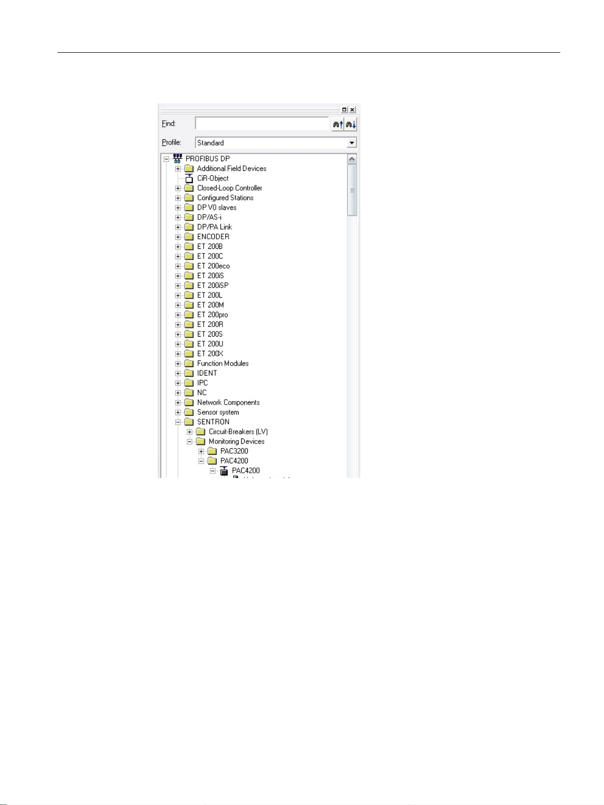
Figure 3-1 Hardware catalog after incorporating the GSD file
Ctrl-Energy
System Manual, 01/2015, 6FC5397-0EP40-5BA2 17
Page 18
Ctrl-E Analysis
3.2 Commissioning the PLC for SENTRON PAC
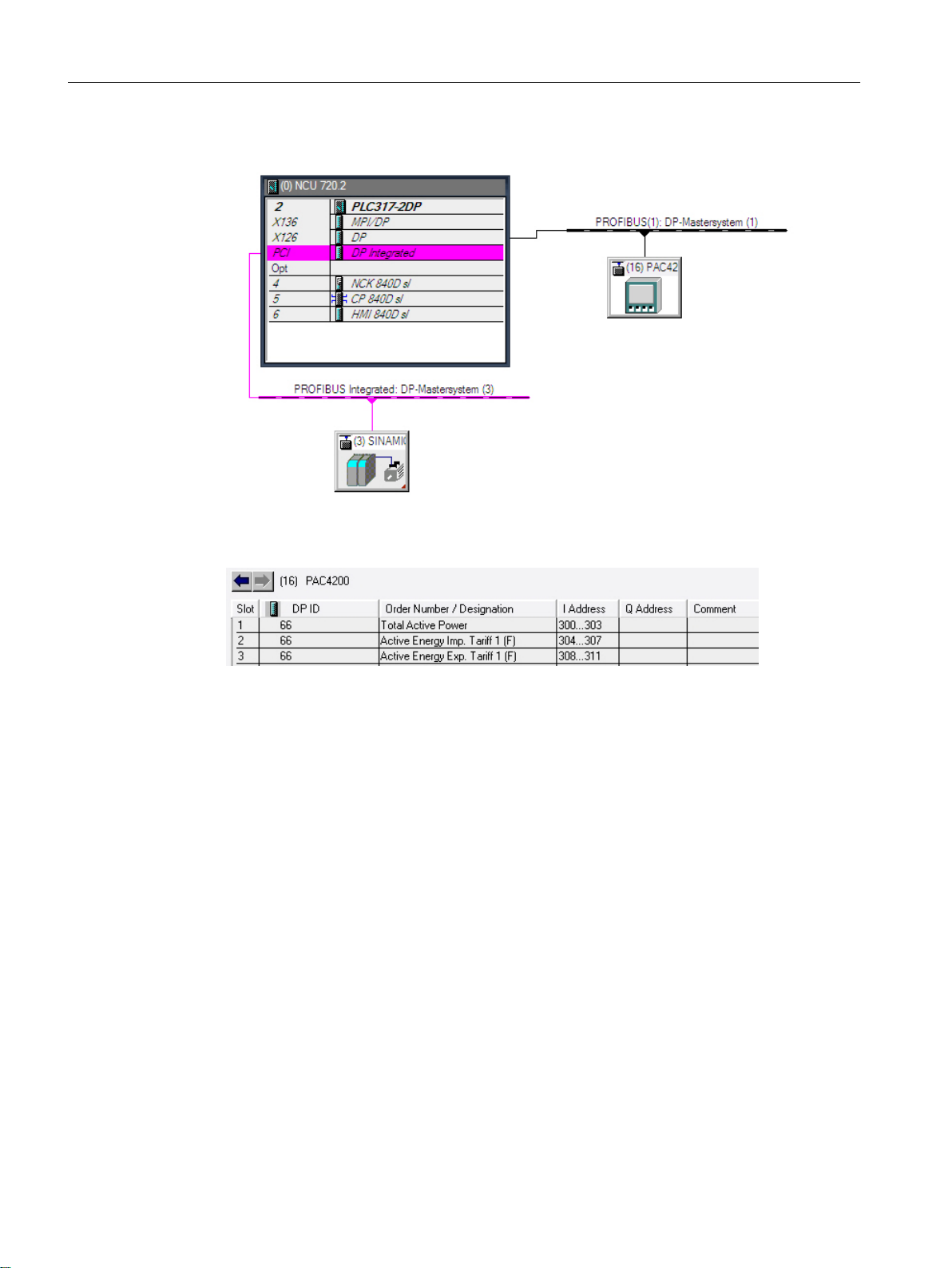
5. In HW Config, drag the selected module to the Profibus DP master system.
6. In the hardware catalog, open the required module and assign the subslots as shown in
the diagram.
Ctrl-Energy
18 System Manual, 01/2015, 6FC5397-0EP40-5BA2
Page 19
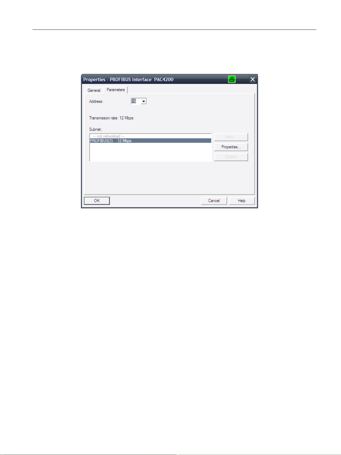
PROFIBUS interface
PROFIBUS must be configured with a data transfer rate of 12 Mbit/s.
Ctrl-E Analysis
3.2 Commissioning the PLC for SENTRON PAC
Setting the PROFIBUS address
Set the PROFIBUS address of the expansion module either directly at the SENTRON PAC or
enter using the powerconfig software.
References
Additional information about commissioning the PLC can be found in the following references:
CNC Commissioning Manual: NCK, PLC, drive / SINUMERIK 840D sl
3.2.1.2 Commissioning the PLC with PROFINET
PROFINET is commissioned with the PLC Toolbox 4.6 or higher. This requires SIMATIC STEP
7 V5.5SP3 or higher.
Preconditions
● Configure the hardware, save and compile the project
● Generating the system data for the PLC
● Install the Toolbox software, which also contains the libraries for the PLC basic program of
an NCU 7x0.3PN.
● GSDML for PAC PROFINET
http://support.automation.siemens.com/WW/view/de/50186868
Ctrl-Energy
System Manual, 01/2015, 6FC5397-0EP40-5BA2 19
Page 20
Ctrl-E Analysis
3.2 Commissioning the PLC for SENTRON PAC
Procedure
You are on the main screen of the SIMATIC Manager.
1. Select the "File" > "Open" menu and then click on the "Libraries" tab.
2. Select the library for the PLC basic program "bp7x0_46" and confirm the dialog with "OK".
3. You have inserted the library and selected the PLC program under "PLC-First-Startup 840D
sl" > "SINUMERIK" > "CPU 317F-3 PN/DP" > "S7 Program".
4. Copy the sources, modules and symbols to the PLC program
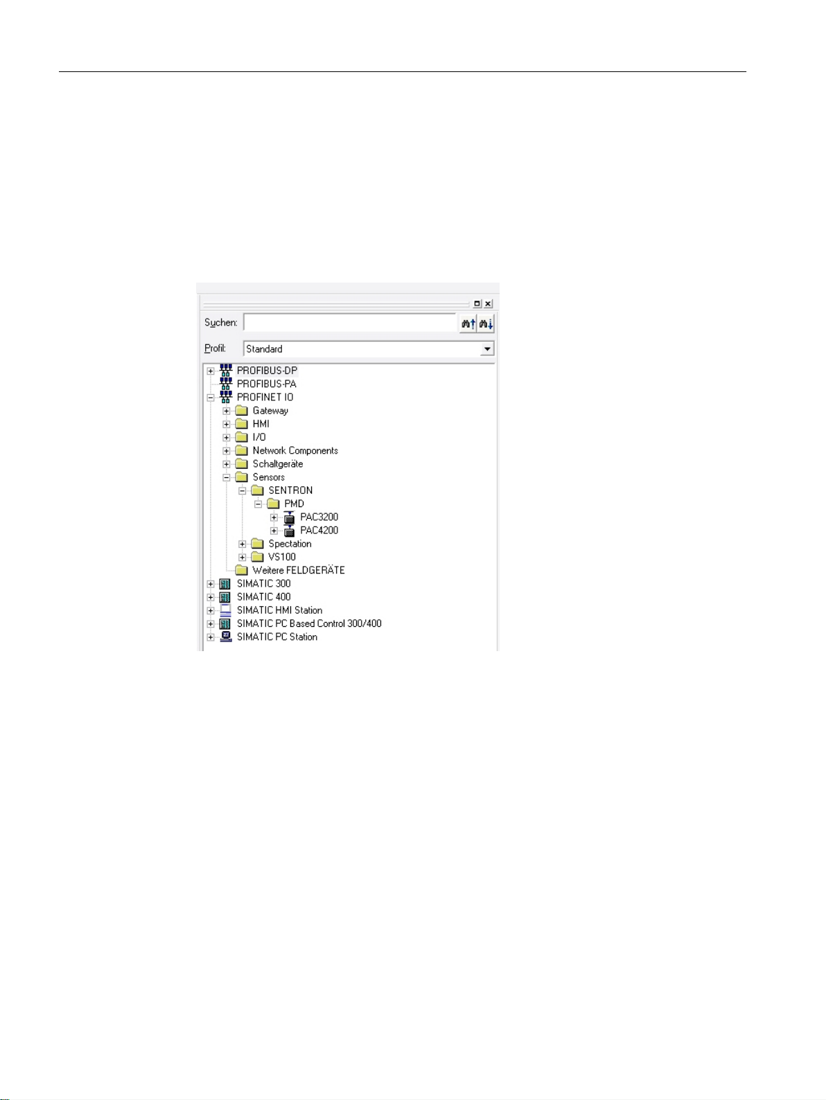
Figure 3-2 Hardware catalog after linking-in the GSDML file
Ctrl-Energy
20 System Manual, 01/2015, 6FC5397-0EP40-5BA2
Page 21
3.2 Commissioning the PLC for SENTRON PAC
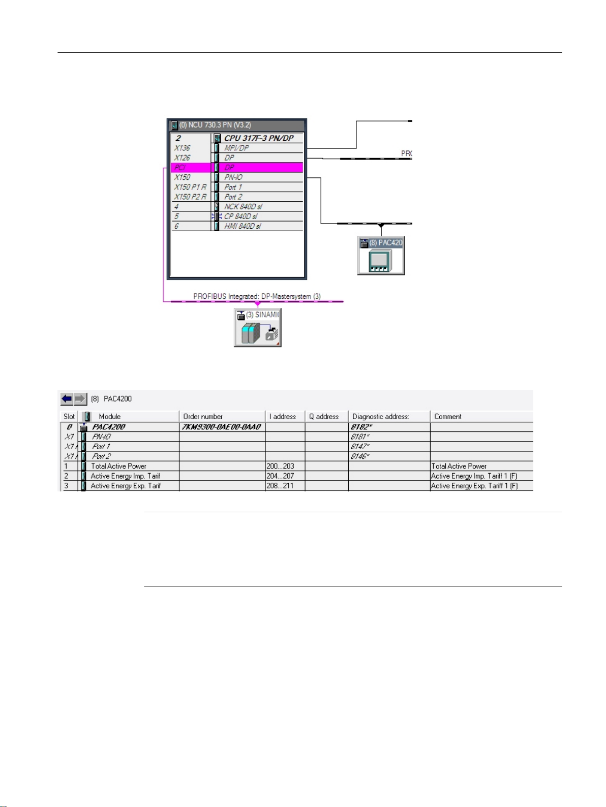
5. In HW Config, drag the selected module to the Profinet IO system.
Ctrl-E Analysis
6. In the hardware catalog, open the required module and assign the subslots as shown in
the diagram.
Note
Port interconnection
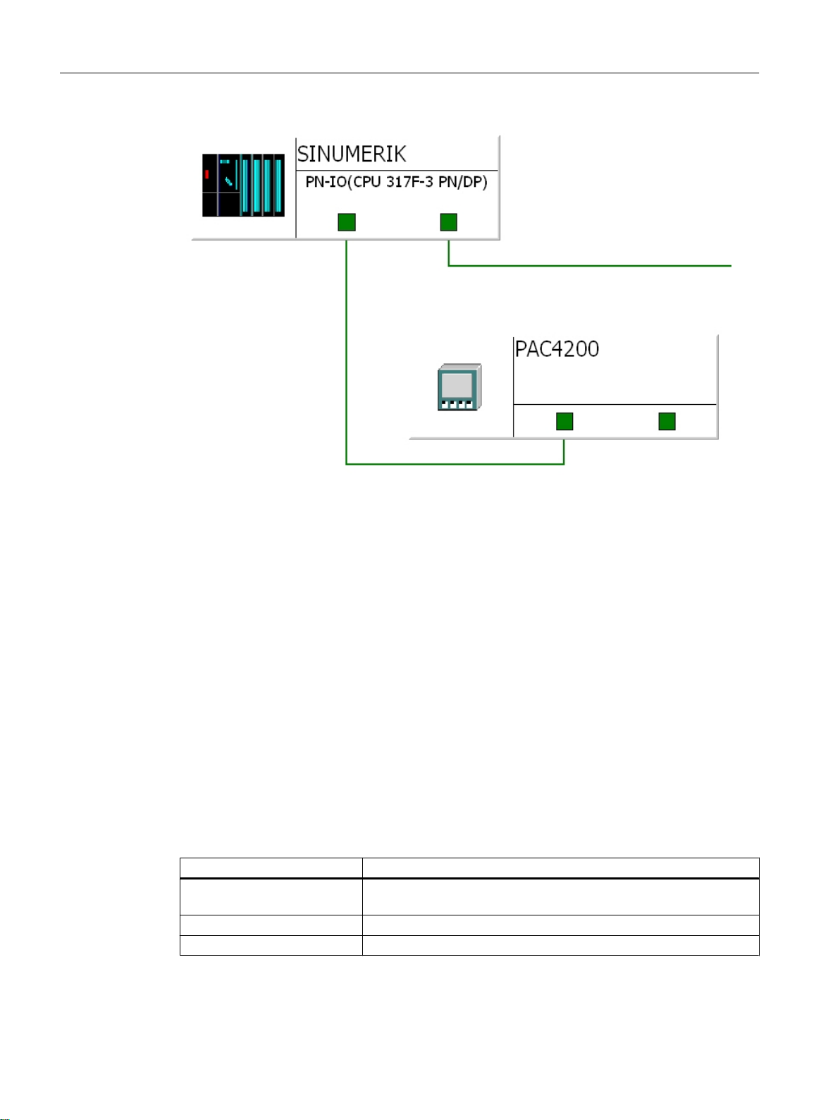
To simplify commissioning, in HW Config configure the PAC PROFINET using port
interconnection at the PROFINET ports of the NCU. This saves you from having to initialize
PAC.
Ctrl-Energy
System Manual, 01/2015, 6FC5397-0EP40-5BA2 21
Page 22
Ctrl-E Analysis
3.2 Commissioning the PLC for SENTRON PAC
References
Additional information about commissioning the PLC can be found in the following references:
CNC Commissioning Manual: NCK, PLC, drive / SINUMERIK 840D sl
3.2.2 SINUMERIK 828D
The PLC of the 828D has a fixed PLC I/O image.
Using the general machine data MD12986[...], the possible peripheral connections (addresses)
are activated or deactivated. When delivered, these addresses are deactivated for the Sentron
devices by entering the address.
Activating the peripheral connection
● SENTRON PAC4200
I address
132 ... 135 Total active power
136 ... 139 Active energy, imported, tariff 1 (instantaneous value)
140 ... 143 Active energy, exported, tariff 1 (instantaneous value)
(value saved from SENTRON PAC)
Ctrl-Energy
22 System Manual, 01/2015, 6FC5397-0EP40-5BA2
Page 23

References
Ctrl-E Analysis
3.3 Commissioning the PLC for Ctrl-E Analysis
For example, you activate the logical input address 132 by changing the machine data MD[...]
with entry 132 to -1.
● SENTRON PAC3200
I address
144 ... 147 Total active power
(value saved from SENTRON PAC)
148 ... 151 Active energy, imported, tariff 1 (instantaneous value)
152 ... 155 Active energy, exported, tariff 1 (instantaneous value)
For example, you activate the logical input address 144 by changing the machine data MD[...]
with entry 144 to -1.
The measured values are transferred in the float format.
Additional information about commissioning the PLC can be found in the following references:
SINUMERIK 828D Turning and Milling Commissioning Manual
3.3 Commissioning the PLC for Ctrl-E Analysis
3.3.1 Configuring the energy consumption display for SINUMERIK 840D sl
The energy consumption is displayed in the "SINUMERIK Ctrl-E Analysis" window.
See also
Signals for controlling energy-saving profiles (Page 44)
Signals for parameterization (Page 45)
The data block can be imported via the Toolbox and is loaded to the NCU via the user program.
Data block
DB1001
Name: SentronPac
DB1001.DBX0.0 PLC -> HMI Display manual value ManualVal BOOL
DB1001.DBX0.1 PLC -> HMI SENTRON PAC rep‐
Signal
direction
Meaning Identifier Format
SentronPacMach BOOL
resents the complete
machine
Ctrl-Energy
System Manual, 01/2015, 6FC5397-0EP40-5BA2 23
Page 24

Ctrl-E Analysis
3.3 Commissioning the PLC for Ctrl-E Analysis
DB1001
Name: SentronPac
DB1001.DBX0.2 PLC -> HMI Imported active ener‐
DB1001.DBX0.3 PLC -> HMI Exported active ener‐
DB1001.DBX1.0 PLC -> GP Measuring request to
DB1001.DBX2.0 HMI -> GP Measurement is run‐
DB1001.DBX3.0 PLC -> HMI Power display shown
DB1001.DBD4 PLC -> HMI Manual value ManualValue REAL
DB1001.DBD8 GP -> HMI Total active power ActivePowerItem REAL
DB1001.DBD12 MeasAuto
DB1001.DBD16 MeasAuto
DB1001.DBD20 PLC -> GP Total active power
DB1001.DBD24 PLC -> GP Imported active ener‐
DB1001.DBD28 PLC -> GP Exported active ener‐
DB1001.DBD32 GP -> HMI Imported active ener‐
DB1001.DBD36 GP -> HMI Exported active ener‐
DB1001.DBD40 GP -> HMI Imported active ener‐
DB1001.DBD44 GP -> HMI Exported active ener‐
Signal
direction
== 0:
PLC -> HMI
MeasAuto
== 1:
GP -> HMI
== 0:
PLC -> HMI
MeasAuto
== 1:
GP -> HMI
Meaning Identifier Format
FeedInEnergyReadSP BOOL
gy is read from SEN‐
TRON PAC
FeedBackEnergyReadSP BOOL
gy is read from SEN‐
TRON PAC
MeasAuto BOOL
PLC basic program
MeasAct BOOL
ning
EStateOn BOOL
in status display
Measured imported
active energy in kWh
to HMI
Measured exported
active energy in kWh
to HMI
in watts from SEN‐
TRON
gy at tariff 1 (F) in Wh
from SENTRON
gy at tariff 1 (F) in Wh
from SENTRON
gy in kWh current day
to HMI
gy in kWh current day
to HMI
gy in kWh previous
day to HMI
gy in kWh previous
day to HMI
ActiveEnergyItem REAL
ReactiveEnergyItem REAL
ActivePowerSentron REAL
ActiveEnergySentron REAL
ReactiveEnergySentron REAL
ActiveEnergyDay REAL
ReactiveEnergyDay REAL
ActiveEnergyPrevDay REAL
ReactiveEnergyPrevDay REAL
Ctrl-Energy
24 System Manual, 01/2015, 6FC5397-0EP40-5BA2
Page 25

Ctrl-E Analysis
3.3 Commissioning the PLC for Ctrl-E Analysis
DB1001
Name: SentronPac
DB1001.DBD48 GP -> HMI Imported active ener‐
DB1001.DBD52 GP -> HMI Exported active ener‐
DB1001.DBD56 GP -> HMI Imported active ener‐
DB1001.DBD60 GP -> HMI Exported active ener‐
DB1001.DBD64 GP -> HMI Imported active ener‐
DB1001.DBD68 GP -> HMI Exported active ener‐
DB1001.DBD72 GP -> HMI Imported active ener‐
DB1001.DBD76 GP -> HMI Exported active ener‐
DB1001.DBB96 PLC -> HMI Presentation of the en‐
Signal
direction
Meaning Identifier Format
gy in kWh month to
HMI
gy in kWh month to
HMI
gy in kWh previous
month to HMI
gy in kWh previous
month to HMI
gy in kWh year to HMI
gy in kWh year to HMI
gy in kWh previous
year to HMI
gy in kWh previous
year to HMI
ergy consumption in
the status display
ActiveEnergyMonth REAL
ReactiveEnergyMonth REAL
ActiveEnergyPrevMonth REAL
ReactiveEnergyPrevMonth REAL
ActiveEnergyYear REAL
ReactiveEnergyYear REAL
ActiveEnergyPrevYear REAL
ReactiveEnergyPrevYear REAL
ProductionAct Byte
Note
Evaluation of the energy consumption of the complete machine
If you have installed SENTRON PAC in the main circuit of the machine or SENTRON PAC
evaluates the energy consumption of the complete machine, set bit DB1001.DBX0.1 to 1.
As a consequence, in the display for Ctrl-E Analysis, the line "SentronPAC" is removed and
the measured value of the SENTRON PAC is entered into the line "Total machine".
Data block for auxiliary systems
Up to 10 auxiliary systems are supported by the data block. A data structure is defined for each
auxiliary system. In order to display the energy/power of an auxiliary system in the HMI, bit 0
of the first byte of the data structure must be set.
Auxiliary system Start of the data structure End of the data structure
Auxiliary system 1 (n=0) DB1001.DBB100 DB1001.DBB139
Auxiliary system 2 (n=40) DB1001.DBB140 DB1001.DBB179
Auxiliary system 3 (n=80) DB1001.DBB180 DB1001.DBB219
Auxiliary system 4 (n=120) DB1001.DBB220 DB1001.DBB259
Auxiliary system 5 (n=160) DB1001.DBB260 DB1001.DBB299
Auxiliary system 6 (n=200) DB1001.DBB300 DB1001.DBB339
Ctrl-Energy
System Manual, 01/2015, 6FC5397-0EP40-5BA2 25
Page 26

Ctrl-E Analysis
3.3 Commissioning the PLC for Ctrl-E Analysis
Auxiliary system Start of the data structure End of the data structure
Auxiliary system 7 (n=240) DB1001.DBB340 DB1001.DBB379
Auxiliary system 8 (n=280) DB1001.DBB380 DB1001.DBB419
Auxiliary system 9 (n=320) DB1001.DBB420 DB1001.DBB459
Auxiliary system 10 (n=360) DB1001.DBB460 DB1001.DBB499
DB1001
Name: SentronPac
DB1001.DBX(100+n).0 PLC ->
DB1001.DBX(100+n).1 PLC ->
DB1001.DBX(100+n).2 PLC ->
DB1001.DBX(100+n).3 PLC ->
DB1001.DBX(100+n).4 PLC ->
DB1001.DBX(100+n).7 PLC ->
DB1001.DBD(104+n) PLC ->
DB1001.DBD(108+n) GP ->
DB1001.DBD(112+n) GP ->
DB1001.DBD(116+n) GP ->
DB1001.DBD(120+n) GP ->
Signal
direction
GP/HMI
GP/HMI
GP/HMI
GP/HMI
GP/HMI
GP/HMI
GP/HMI
HMI
HMI
HMI
HMI
Meaning Identifier Format
GP calculates the energy/
power of the auxiliary sys‐
tem
Actual value update ReadEnergy BOOL
Measurement in progress MeasACT BOOL
1: Differential values are
written to the variables for
the measurement end
0: Absolute values are
written to the variables for
the measurement start
and measurement end
1: Energy
0: Power
Delete data structure ResetAux BOOL
Active power or active en‐
ergy of the auxiliary sys‐
tem
Active energy drawn by
the auxiliary system in
kWh
Active energy supplied by
the auxiliary system in
kWh
Active energy drawn by
the auxiliary system at
the measurement start in
kWh
Active energy supplied by
the auxiliary system at
the measurement start in
kWh
ProcessAux BOOL
MeasMode BOOL
InputMode BOOL
ActivePowerAux REAL
ActiveEnAux REAL
ReActiveEnAux REAL
ActiveEnAuxMeasON REAL
ReActiveEnAuxMeasON REAL
Ctrl-Energy
26 System Manual, 01/2015, 6FC5397-0EP40-5BA2
Page 27

Ctrl-E Analysis
3.3 Commissioning the PLC for Ctrl-E Analysis
DB1001
Name: SentronPac
DB1001.DBD(124+n) GP ->
DB1001.DBD(128+n) GP ->
Signal
direction
HMI
HMI
Meaning Identifier Format
Active energy drawn by
the auxiliary system at
the measurement end in
kWh
Active energy supplied by
the auxiliary system at
the measurement end in
kWh
3.3.1.1 PLC user program for SINUMERIK 840D sl programming
Via the expansion modules, SENTRON PAC devices provide the total active power in the unit
W and the active energy data in Wh. In HMI the units kW and kWh are used.
PLC basic program
The PLC basic program offers the following functions:
● Provision of the total active power [kW]
● Provision of the values for imported and exported active energy [kWh]
for the current day, month and the current year as well as for the previous day, previous
month and the previous year.
The values of the current time periods are updated in every cycle. If one of the time periods
changes (new day, new month or new year) then the "current" variables of the time period
that changes is copied into its previous day, previous month or previous year variables and
the "current" variables are accumulated again starting from 0.
ActiveEnAuxMeasOFF REAL
ReActiveEnAuxMeasOFF REAL
● Two measuring procedures for imported and exported active energy [kWh]
– Measuring carried out by the basic program
– The user calculates and writes the measured values
This allows user-specific measuring routines to be implemented.
The two values of measured imported energy [kWh] (DBD12) and the measured exported
energy [kWh] (DBD16) are made available for the HMI. The source of the values as well as
measuring procedure and measuring duration (start, stop) are defined using measurement
control bits.
Programming the PLC user program
● You take the total active power from the input address and transfer the value to
DB1001.DBD20.
● You take the imported active power from the input address and transfer the value to
DB1001.DBD24.
● You take the exported active power from the input address and transfer the value to
DB1001.DBD28.
Ctrl-Energy
System Manual, 01/2015, 6FC5397-0EP40-5BA2 27
Page 28

Ctrl-E Analysis
3.3 Commissioning the PLC for Ctrl-E Analysis
● If the control bits DB1001.DBX0.2 and DBX0.3 are equal to 0, then the HMI counts the
energy on the basis of the total active power transferred from the SENTRON between the
start and stop.
● If the imported and exported energy is to be directly evaluated by SENTRON PAC
(DB1001.DBX0.2 and DBX0.3 equal to 1), then program this measurement in the user
program as follows:
– SENTRON PAC devices permanently cumulate the "imported active energy (tariff 1)"
or "the exported active energy (tariff 1)" separately when their supply voltages are
connected.
– With the positive edge of the signal "Measurement running" (DB1001.DBX2.0) you
buffer these instantaneous values from SENTRON (imported and exported active
energy T1)
– Cyclically generate the differences between the energy data now being counted minus
the initial values, divide the differences by 1000.0 and transfer the results to
DB1001.DBD12 (for measured imported active energy T1) and DB1001.DBD16
(measured exported active energy T1) up to the STOP signal (falling edge).
– During the measurement, the increasing difference (energy in kWh) is displayed on the
HMI, which can then be read as measured value with Stop measurement.
Measurement control HMI → GP and PLC → GP
● With a 1 signal of the control bit "MeasAuto" (DBX1.0), the user requests that the basic
program makes the measurement.
If this bit is not set, then the user is responsible for calculating and writing the measured
values.
● Using a 1 signal of the control bit "MeasAct" (DBX2.0), via the HMI it is signaled as to when
the measurement should be made: 0→1 start measurement, 1→0 stop measurement.
The basic program only evaluates this signal if control bit "MeasAuto" (DBX1.0) is set.
Measurement carried out by the basic program:
For these measurements, the cyclic increases in the energy values are accumulated in the
measured variables.
Ctrl-Energy
28 System Manual, 01/2015, 6FC5397-0EP40-5BA2
Page 29
0HDVXUHG
YDOXH
'%;
'%;
0HDVXUHG
YDOXH
'%;
'%;
Ctrl-E Analysis
3.3 Commissioning the PLC for Ctrl-E Analysis
The behavior for different signal sequences of both measurement control signals are described
in the following:
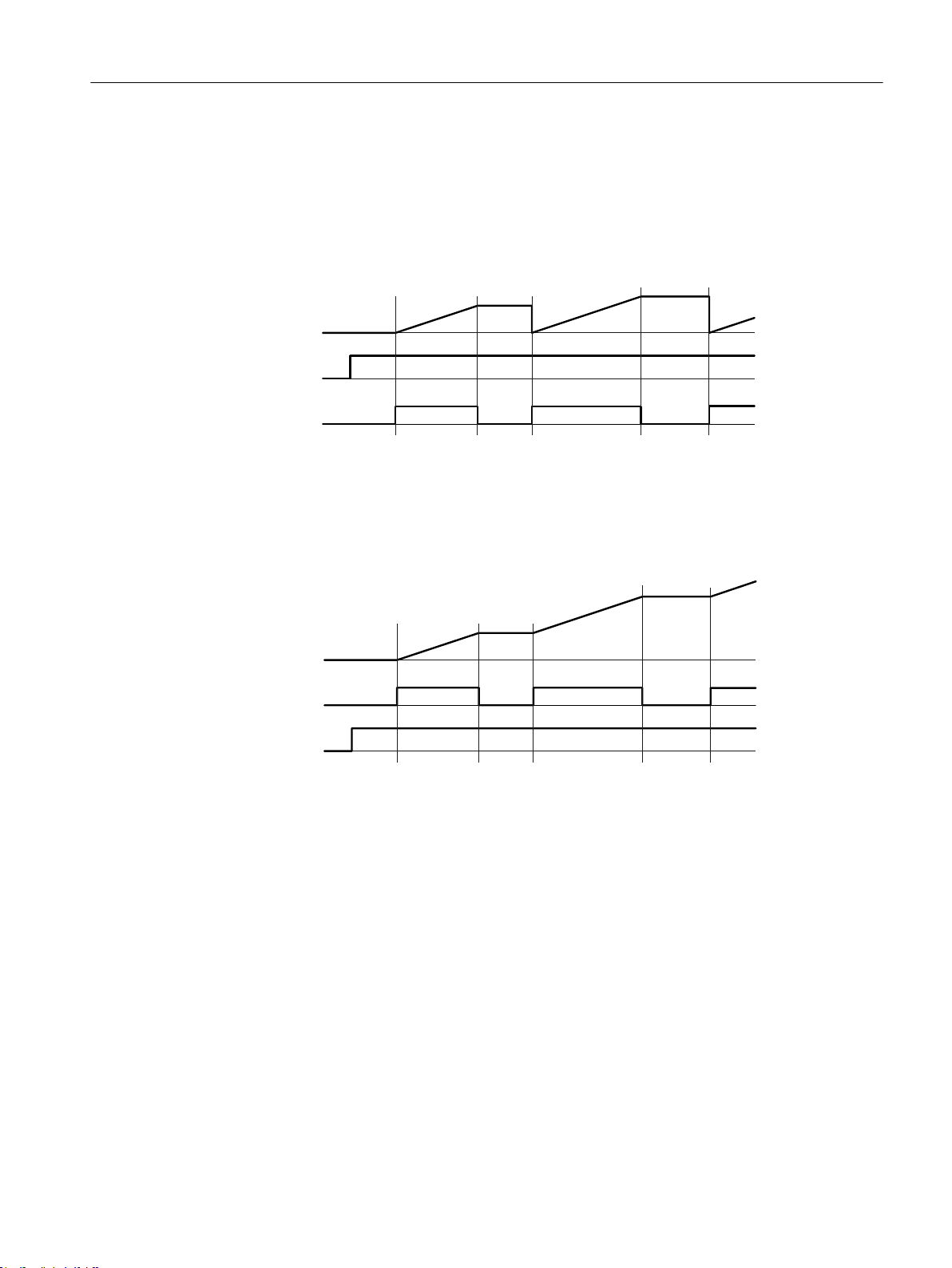
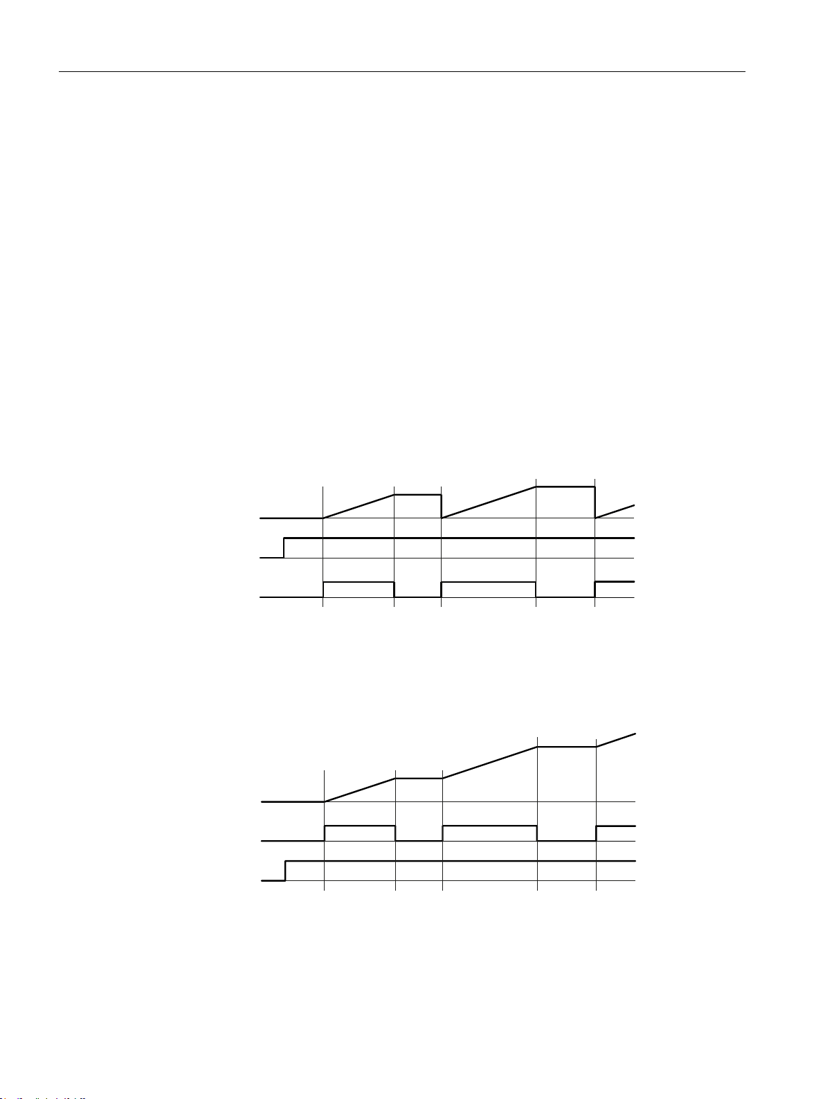
● DBX1.0 is set first
If DBX1.0 ("MeasAuto") is first set, and then remains statically present, every 0-1 edge of
DBX2.0 ("MeasAct") deletes the measured value and then starts the measurement.
If DBX2.0 is reset, the measurement is canceled and the measured value remains constant.
The sequence is repeated at the next 0-1 edge of DBX2.0.
Figure 3-3 Measurement control signal DBX1.0 is set first
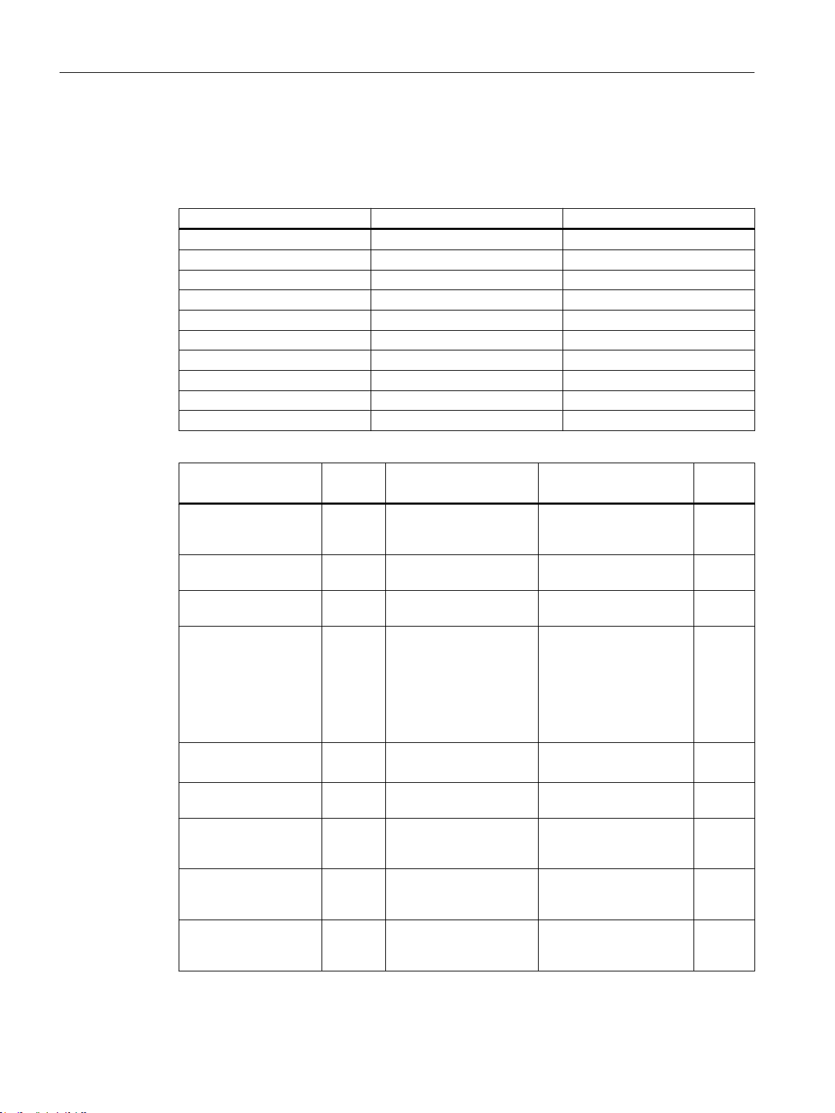
● DBX2.0 is set first
If DBX2.0 ("MeasAct") is set first, and then remains statically present, every 0-1 edge of
DBX1.0 ("MeasAuto") accumulates the measured value without deleting the previous value.
If DBX1.0 is reset, the measurement is only interrupted and the measured value remains
constant.
Figure 3-4 Measurement control signal DBX2.0 is set first
3.3.2 Configuring the display of energy consumption for SINUMERIK 828D
The energy consumption is displayed in the "SINUMERIK Ctrl-E Analysis" window.
See also
Signals for controlling energy-saving profiles (Page 46)
Signals for parameterization (Page 47)
Ctrl-Energy
System Manual, 01/2015, 6FC5397-0EP40-5BA2 29
Page 30

Ctrl-E Analysis
3.3 Commissioning the PLC for Ctrl-E Analysis
Data block
DB9907
Name: Sentron‐
Pac
DB9907.DBX0.0 PLC -> HMI Display manual value ManualVal BOOL
DB9907.DBX0.1 PLC -> HMI SENTRON PAC rep‐
DB9907.DBX0.2 PLC -> HMI Imported active ener‐
DB9907.DBX0.3 PLC -> HMI Exported active ener‐
DB9907.DBX1.0 PLC -> FW Measuring request to
DB9907.DBX2.0 HMI -> FW Measurement is run‐
DB9907.DBD4 PLC -> HMI Manual value ManualValue REAL
DB9907.DBD8 FW -> HMI Total active
DB9907.DBD12 MeasAuto
DB9907.DBD16 MeasAuto
DB9907.DBD20 PLC -> FW Total active
DB9907.DBD24 PLC -> FW Imported active ener‐
DB9907.DBD28 PLC -> FW Exported active ener‐
DB9907.DBD32 FW -> HMI Imported active ener‐
Signal
direction
== 0:
PLC -> HMI
MeasAuto
== 1:
FW -> HMI
== 0:
PLC -> HMI
MeasAuto
== 1:
FW -> HMI
Meaning Symbol Format
SentronPacMach BOOL
resents the complete
machine
FeedInEnergyReadSP BOOL
gy is read from SEN‐
TRON PAC
FeedBackEnergyReadSP BOOL
gy is read from SEN‐
TRON PAC
MeasAuto BOOL
PLC FW
MeasAct BOOL
ning
ActivePowerItem REAL
power
Measured imported
active energy tariff1
Measured exported
active energy tariff1
power
in watts from SEN‐
TRON
gy at tariff 1 (F) in Wh
from SENTRON
gy at tariff 1 (F) in Wh
from SENTRON
gy in kWh current day
to HMI
ActiveEnergyItem REAL
ReactiveEnergyItem REAL
ActivePowerSentron REAL
ActiveEnergySentron REAL
ReactiveEnergySentron REAL
ActiveEnergyDay REAL
Ctrl-Energy
30 System Manual, 01/2015, 6FC5397-0EP40-5BA2
Page 31

Ctrl-E Analysis
3.3 Commissioning the PLC for Ctrl-E Analysis
DB9907
Name: Sentron‐
Pac
DB9907.DBD36 FW -> HMI Exported active ener‐
DB9907.DBD40 FW -> HMI Imported active ener‐
DB9907.DBD44 FW -> HMI Exported active ener‐
DB9907.DBD48 FW -> HMI Imported active ener‐
DB9907.DBD52 FW -> HMI Exported active ener‐
DB9907.DBD56 FW -> HMI Imported active ener‐
DB9907.DBD60 FW -> HMI Exported active ener‐
DB9907.DBD64 FW -> HMI Imported active ener‐
DB9907.DBD68 FW -> HMI Exported active ener‐
DB9907.DBD72 FW -> HMI Imported active ener‐
DB9907.DBD76 FW -> HMI Exported active ener‐
Signal
direction
Meaning Symbol Format
gy in kWh current day
to HMI
gy in kWh previous
day to HMI
gy in kWh previous
day to HMI
gy in kWh month to
HMI
gy in kWh month to
HMI
gy in kWh previous
month to HMI
gy in kWh previous
month to HMI
gy in kWh year to HMI
gy in kWh year to HMI
gy in kWh previous
year to HMI
gy in kWh previous
year to HMI
ReactiveEnergyDay REAL
ActiveEnergyPrevDay REAL
ReactiveEnergyPrevDay REAL
ActiveEnergyMonth REAL
ReactiveEnergyMonth REAL
ActiveEnergyPrevMonth REAL
ReactiveEnergyPrevMonth REAL
ActiveEnergyYear REAL
ReactiveEnergyYear REAL
ActiveEnergyPrevYear REAL
ReactiveEnergyPrevYear REAL
Note
Evaluation of the energy consumption of the complete machine
If you have installed SENTRON PAC in the main circuit of the machine or SENTRON PAC
evaluates the energy consumption of the complete machine, set bit DB9907.DBX0.1 to 1.
As a consequence, in the display for Ctrl-E Analysis, the line "SentronPAC" is removed and
the measured value of the SENTRON PAC is entered into the line "Total machine".
Ctrl-Energy
System Manual, 01/2015, 6FC5397-0EP40-5BA2 31
Page 32
Ctrl-E Analysis
3.3 Commissioning the PLC for Ctrl-E Analysis
Data block for auxiliary systems
Up to 10 auxiliary systems are supported by the data block. A data structure is defined for each
auxiliary system. In order to display the energy/power of an auxiliary system in the HMI, bit 0
of the first byte of the data structure must be set.
Auxiliary system Start of the data structure End of the data structure
Auxiliary system 1 (n=0) DB9907.DBB100 DB9907.DBB139
Auxiliary system 2 (n=40) DB9907.DBB140 DB9907.DBB179
Auxiliary system 3 (n=80) DB9907.DBB180 DB9907.DBB219
Auxiliary system 4 (n=120) DB9907.DBB220 DB9907.DBB259
Auxiliary system 5 (n=160) DB9907.DBB260 DB9907.DBB299
Auxiliary system 6 (n=200) DB9907.DBB300 DB9907.DBB339
Auxiliary system 7 (n=240) DB9907.DBB340 DB9907.DBB379
Auxiliary system 8 (n=280) DB9907.DBB380 DB9907.DBB419
Auxiliary system 9 (n=320) DB9907.DBB420 DB9907.DBB459
Auxiliary system 10 (n=360) DB9907.DBB460 DB9907.DBB499
DB9907
Name: SentronPac
DB9907.DBX(100+n).0 PLC ->
DB9907.DBX(100+n).1 PLC ->
DB9907.DBX(100+n).2 PLC ->
DB9907.DBX(100+n).3 PLC ->
DB9907.DBX(100+n).4 PLC ->
DB9907.DBX(100+n).7 PLC ->
DB9907.DBD(104+n) PLC ->
DB9907.DBD(108+n) FW ->
DB9907.DBD(112+n) FW ->
Signal
direction
FW/HMI
FW/HMI
FW/HMI
FW/HMI
FW/HMI
FW/HMI
FW/HMI
HMI
HMI
Meaning Identifier Format
FW calculates the energy/
power of the auxiliary sys‐
tem
Actual value update ReadEnergy BOOL
Measurement in progress MeasACT BOOL
1: Differential values are
written to the variables for
the measurement end
0: Absolute values are
written to the variables for
the measurement start
and measurement end
1: Energy
0: Power
Delete data structure ResetAux BOOL
Active power or active en‐
ergy of the auxiliary sys‐
tem
Active energy drawn by
the auxiliary system in
kWh
Active energy supplied by
the auxiliary system in
kWh
ProcessAux BOOL
MeasMode BOOL
InputMode BOOL
ActivePowerAux REAL
ActiveEnAux REAL
ReActiveEnAux REAL
Ctrl-Energy
32 System Manual, 01/2015, 6FC5397-0EP40-5BA2
Page 33

Ctrl-E Analysis
3.3 Commissioning the PLC for Ctrl-E Analysis
DB9907
Name: SentronPac
DB9907.DBD(116+n) FW ->
DB9907.DBD(120+n) FW ->
DB9907.DBD(124+n) FW ->
DB9907.DBD(128+n) FW ->
Signal
direction
HMI
HMI
HMI
HMI
Meaning Identifier Format
Active energy drawn by
the auxiliary system at
the measurement start in
kWh
Active energy supplied by
the auxiliary system at
the measurement start in
kWh
Active energy drawn by
the auxiliary system at
the measurement end in
kWh
Active energy supplied by
the auxiliary system at
the measurement end in
kWh
ReActiveEnAuxMeasON REAL
ReActiveEnAuxMeasOFF REAL
3.3.2.1 Programming the PLC user program for SINUMERIK 828D
Via the expansion modules, SENTRON PAC devices provide the total active power in the unit
W and the active energy data in Wh. In HMI the units kW and kWh are used.
ActiveEnAuxMeasON REAL
ActiveEnAuxMeasOFF REAL
PLC firmware
The PLC firmware offers the following functions:
● Provision of the total active power [kW]
● Provision of the values for imported and exported active energy [kWh]
for the current day, month and the current year as well as for the previous day, previous
month and the previous year.
The values of the current time periods are updated in every cycle. If one of the time periods
changes (new day, new month or new year) then the "current" variables of the time period
that changes is copied into its previous day, previous month or previous year variables and
the "current" variables are accumulated again starting from 0.
● Two measuring procedures for imported and exported active energy [kWh]
– Measurement carried out by the PLC firmware (see "Measurement control HMI → FW
and PLC → FW")
– The user calculates and writes the measured values
This allows user-specific measuring routines to be implemented.
The two values of measured imported energy [kWh] (DBD12) and the measured exported
energy [kWh] (DBD16) are made available for the HMI. The source of the values as well as
measuring procedure and measuring duration (start, stop) are defined using measurement
control bits.
Ctrl-Energy
System Manual, 01/2015, 6FC5397-0EP40-5BA2 33
Page 34
Ctrl-E Analysis
3.3 Commissioning the PLC for Ctrl-E Analysis
Programming the PLC user program
● You take the total active power from the input address and transfer the value to
DB9907.DBD20. This must be realized according to the following point "Adapt byte
sequence".
● You take the imported active power from the input address and transfer the value to
DB9907.DBD24. This must be realized according to the following point "Adapt byte
sequence".
● You take the exported active power from the input address and transfer the value to
DB9907.DBD28. This must be realized according to the following point "Adapt byte
sequence".
● If the control bits DB9907.DBX0.2 and DBX0.3 are equal to 0, then the HMI counts the
energy on the basis of the total active power transferred from the SENTRON between the
start and stop.
● If the imported and exported energy is to be directly evaluated by SENTRON PAC
(DB9907.DBX0.2 and DBX0.3 equal to 1), then program this measurement in the user
program as follows:
– SENTRON PAC devices permanently cumulate the "imported active energy (tariff 1)"
or "the exported active energy (tariff 1)" separately when their supply voltages are
connected.
– With the positive edge of the signal "Measurement running" (DB9907.DBX2.0) you
buffer these instantaneous values from SENTRON (imported and exported active
energy T1)
– Cyclically generate the differences between the energy data now being counted minus
the initial values, divide the differences by 1000.0 and transfer the results to
DB9907.DBD12 (for measured imported active energy T1) and DB9907.DBD16
(measured exported active energy T1) up to the STOP signal (falling edge).
– During the measurement, the increasing difference (energy in kWh) is displayed on the
HMI, which can then be read as measured value with Stop measurement.
Adapting the byte sequence
Save the values of the SENTRON PAC so that the byte sequence of the double words is
swapped over (Endian conversion).
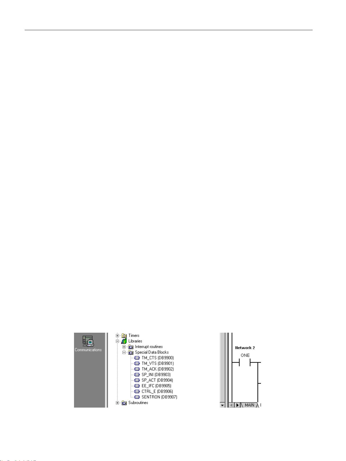
The CTRL_E and SENTRON blocks are located in the following directory:
Ctrl-Energy
34 System Manual, 01/2015, 6FC5397-0EP40-5BA2
Page 35
Ctrl-E Analysis
3.3 Commissioning the PLC for Ctrl-E Analysis
Example for SINUMERIK 828D with SENTRON PAC3200
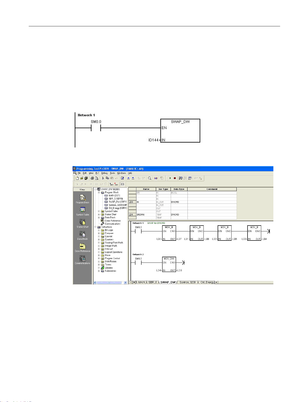
Swap over the byte sequence of the total active power in ID144:
For the total active power, the numerical value of 18.4 is supplied from SENTRON. This
corresponds to a hexadecimal value of 0x41933334, which is located just like this in the double
word ID144. To be further processed by the PLC, the sequence of these four bytes must be
swapped over: 0x34339341.
Also the values for the active energy import tariff 1 and active energy export tariff 1 must be
handled in this way.
Figure 3-5 SWAP_DW subroutine
Figure 3-6 Byte sequence
You can find the SWAP_DW subroutine on the Toolbox-CD under Examples\PLC
Ctrl-Energy
System Manual, 01/2015, 6FC5397-0EP40-5BA2 35
Page 36
0HDVXUHG
YDOXH
'%;
'%;
0HDVXUHG
YDOXH
'%;
'%;
Ctrl-E Analysis
3.3 Commissioning the PLC for Ctrl-E Analysis
Measurement control HMI → FW and PLC → FW
● With a 1 signal of the control bit "MeasAuto" (DBX1.0), the user requests that the firmware
makes the measurement.
If this bit is not set, then the user is responsible for calculating and writing the measured
values.
● Using a 1 signal of the control bit "MeasAct" (DBX2.0), via the HMI it is signaled as to when
the measurement should be made: 0→1 start measurement, 1→0 stop measurement.
The firmware only evaluates this signal if control bit "MeasAuto" (DBX1.0) is set.
Measurement carried out by the firmware
For these measurements, the cyclic increases in the energy values are accumulated in the
measured variables.
The behavior for different signal sequences of both measurement control signals are described
in the following:
● DBX1.0 is set first
If DBX1.0 ("MeasAuto") is first set, and then remains statically present, every 0-1 edge of
DBX2.0 ("MeasAct") deletes the measured value and then starts the measurement.
If DBX2.0 is reset, the measurement is canceled and the measured value remains constant.
The sequence is repeated at the next 0-1 edge of DBX2.0.
Figure 3-7 Measurement control signal DBX1.0 is set first
● DBX2.0 is set first
If DBX2.0 ("MeasAct") is set first, and then remains statically present, every 0-1 edge of
DBX1.0 ("MeasAuto") accumulates the measured value without deleting the previous value.
If DBX1.0 is reset, the measurement is only interrupted and the measured value remains
constant.
Figure 3-8 Measurement control signal DBX2.0 is set first
Ctrl-Energy
36 System Manual, 01/2015, 6FC5397-0EP40-5BA2
Page 37

3.4 Commissioning the HMI for Ctrl-E Analysis
3.4 Commissioning the HMI for Ctrl-E Analysis
No additional adaptation is required.
As soon as the DB1001 (840D sl) or the DB9907 (828D) is available and actively assigned
with data words, then the HMI automatically accepts this data.
If you have configured auxiliary systems, these devices are displayed as "AUX1" to "AUX10"
in the Ctrl-E analysis. You can assign these devices language-dependent display texts.
3.4.1 Changing display texts of the auxiliary systems
The display texts for the auxiliary systems are stored in the "slnrgauxunits_xxx.ts" file. A
dedicated file must be created for each supported language. The file names differ by the
language code. Set the appropriate language code for "xxx" (e.g. "slnrgauxunits_eng.ts" for
English).
Structure of the "slnrgauxunits_xxx.ts" file
Ctrl-E Analysis
Procedure
In the "slnrgauxunits_xxx.ts" file, the text identifiers from the software are assigned languagedependent texts.
Tag Meaning
source Text identifier
The auxiliary systems are identified with "AUX_UNIT_1" to
"AUX_UNIT_10".
translation Text which is displayed on the user interface.
You can enter single and multi-line texts. "%n" is used to generate a line
break.
chars Text length (number of characters)
lines Number of lines
1. Copy the "slnrgauxunits_deu.ts" template file from the directory: siemens/sinumerik/
hmi/template/lng.
2. Save the file to the /oem/sinumerik/hmi/lng or /user/sinumerik/hmi/lng
directory.
3. If required, change the file name.
If you wish to create texts for additional languages, then a separate file must be created
for each language. Save the file with the appropriate language code in the file name.
4. Open the file and enter the text to be displayed between the <translation> and </translation>
tags.
5. Restart SINUMERIK Operate.
The file must still be converted into a binary format so that the texts can be displayed during
the program runtime. This conversion is only executed when the HMI powers up.
Ctrl-Energy
System Manual, 01/2015, 6FC5397-0EP40-5BA2 37
Page 38

Ctrl-E Analysis
3.6 Power display in the status line of the "Machine" operating area
3.5 Long time measurement
In order that you can read the usage values in the Ctrl-Energy initial window and in the "Long
time measurement" window, program the PLC user program as specified in Chapter 2.3.1.1
(840D sl) or 2.3.2.1 (828D).
3.6 Power display in the status line of the "Machine" operating area
The current energy consumption is displayed in the first line of the status display in the
"Machine" operating area in the form of colored bars.
To show the power display set DB1001.DBX3.0 = 1 in the STEP 7 program of the PLC.
The following machine statuses are displayed:
Displaying the machine status
DB1001.DBB96 = 0 Red bar upwards – the machine is unproductive
DB1001.DBB96 = 1 Dark green bar upwards – the machine is productive and consumes
energy
DB1001.DBB96 = 2 Light green bar downwards – the machine feeds energy back into
the line supply (generator operation)
Ctrl-Energy
38 System Manual, 01/2015, 6FC5397-0EP40-5BA2
Page 39

Ctrl-E Profiles
To optimize the energy consumption, you have the option of defining energy saving profiles
and saving them.
Controlling the energy-saving states of the machine
The following pre-defined energy-saving profiles are available when the system is delivered:
● Simple energy-saving mode (machine standby)
A specific interface signal is initiated if the control has not exited the reset state after a
defined time. Using this signal, with the PLC a pre-defined energy state is established,
where, for example it is still possible to operate the machine for setting-up purposes.
● Full energy-saving mode (NC standby)
A specific interface signal is initiated if none of the keys on the machine control panel at
the control has been pressed for a specific time. A pre-defined energy state can be
established with the PLC using this signal, where it is still possible, for example, to transfer
programs to the control or edit them.
● Maximum energy-saving mode (auto shut-off)
An additional interface signal is initiated if, at the control, no key on the operator panel and
machine control panel has been pressed for a defined time and there is no active
communication with the external device. Via the PLC, the main switch is automatically
opened, e.g. using the undervoltage release function.
4
These predefined energy-saving profiles only become effective if the control system is in the
reset state. They can be blocked using a PLC user signal. The energy-saving profiles can be
changed at any time and supplemented to include up to a total of 8 profiles.
For instance, you have the option of assigning a customer key to an energy-saving profile,
with which the control can be immediately shut down.
4.1 Commissioning the PLC for Ctrl-E Profiles
4.1.1 Overview
In every machine tool, the PLC is the central part of the control for the peripherals and mounted
equipment/devices. Each machine can have several operating stations.
The energy-saving profiles are managed and stored in the PLC. The signals to monitor energy
within the machine are available in the PLC; these signals can then be appropriately logically
combined in the PLC user program.
Ctrl-Energy
System Manual, 01/2015, 6FC5397-0EP40-5BA2 39
Page 40

Ctrl-E Profiles
4.1 Commissioning the PLC for Ctrl-E Profiles
SINUMERIK 840D sl
In SINUMERIK 840D sl, "Ctrl+Energy" is integrated in the basic program (FB15). Data for each
energy-saving profile is saved in DB1000, which is supplied with the Toolbox.
SINUMERIK 828D
In SINUMERIK 828D, "Ctrl+Energy" is integrated in the PLC firmware. The data for each
energy-saving profile is saved in the DB9906, which is included in the Programming Tool 828D.
In the other versions, for the "basic program (FB15)" for 828D, "PLC firmware" applies.
Energy-saving profiles
The PLC supports 8 energy-saving profiles. After the relevant configured delay times have
expired, the energy-saving profiles are individually active. The total time up until the energysaving profile is activated is obtained from its activation time plus the prewarning time. During
the two time intervals, the selected signals, enabled using masking, are monitored for any
activity and the profile only becomes finally active when the signals are completely inactive.
Of course, when required OEMs can configure either one or both times with zero.
The energy-saving profile in the PLC is characterized by the following data:
● the maximum time for T1 – the activation time
● the maximum time for T2 – the prewarning limit time of the user
● the actual value for T1
● the actual value for T2
● masking of the signals to assume/exit the energy-saving state
The times have the units of seconds, are 16 bits wide and unsigned. A maximum time is
therefore approximately 18 hours.
Note
The time until the energy-saving profile has been finally activated is obtained by adding the
actual values of T1 and T2
The data for each energy-saving profile is saved in DB1000 for the 840Dsl and in DM9906 for
the 828D.
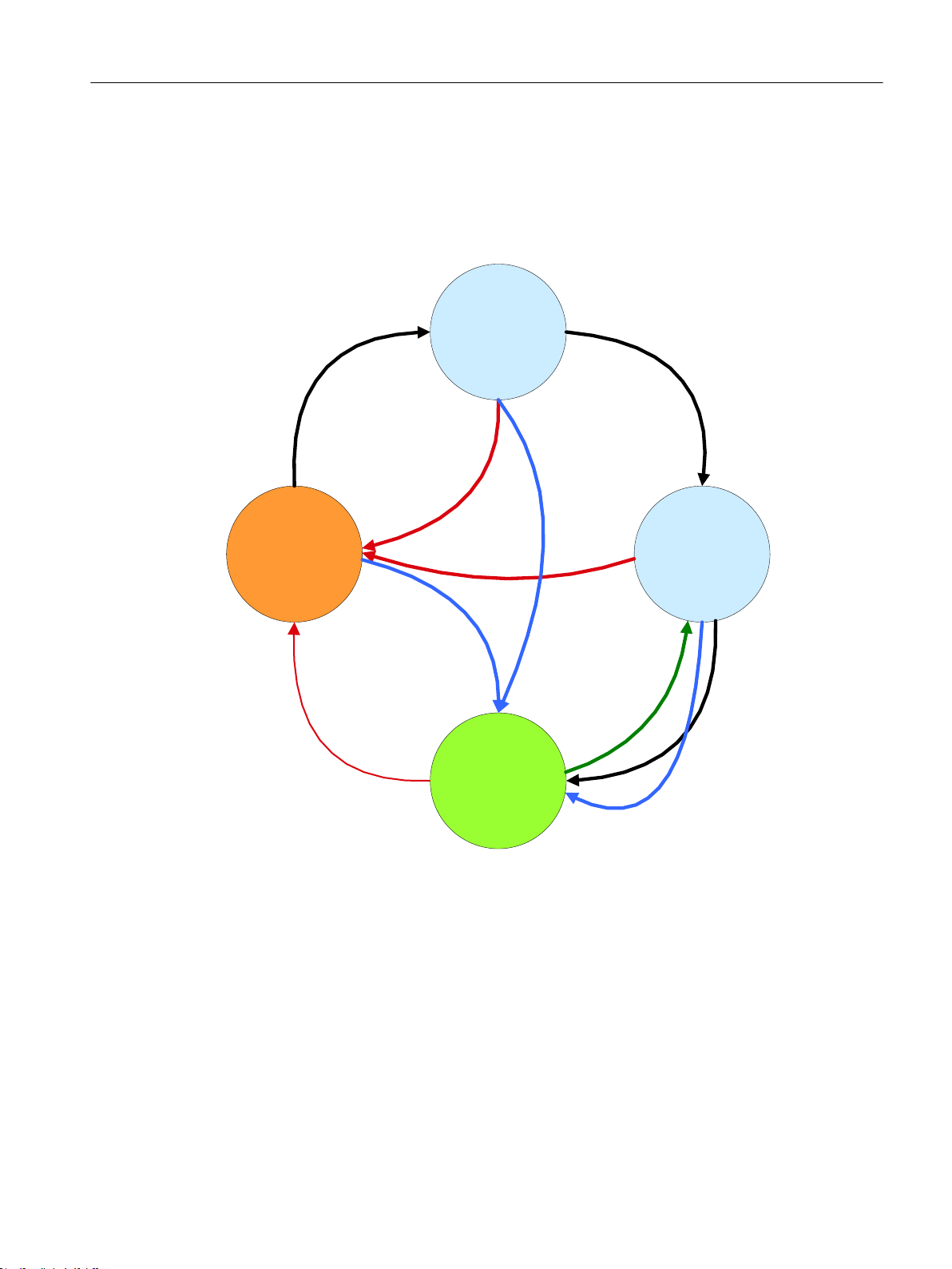
4.1.2 Automatic state machine PLC functions
The automatic state machine shows the functionality in the PLC.
The state transition "OFF" results in a change into the "Energy-saving state inactive" from
every other state. This corresponds to "waking up" the machine.
After the NCU powered up, every energy-saving profile in the state "Energy-saving state
inactive" and the actual values of the times T1 and T2 are set to the maximum values.
Ctrl-Energy
40 System Manual, 01/2015, 6FC5397-0EP40-5BA2
Page 41
7UDQVLWLRQ
581
7UDQVLWLRQ
581
7UDQVLWLRQ
581
7KDVH[SLUHG
'LUHFWO\DFWLYDWH
HQHUJ\VDYLQJSURILOH
VHW
'LUHFWO\DFWLYDWH
HQHUJ\VDYLQJSURILOH
VHW
7UDQVLWLRQ
2))
'LUHFWO\DFWLYDWH
HQHUJ\VDYLQJSURILOH
VHW
6HWWLPHWR
SUHZDUQLQJOLPLW
ORDG7ZLWK
VHWSRLQW
7UDQVLWLRQ
2))
7UDQVLWLRQ
2))
7KDVH[SLUHG
(QHUJ\
VDYLQJVWDWH
LQDFWLYH
(QHUJ\
VDYLQJVWDWH
DFWLYH
7LPHU7
LV
GHFUHPHQWHG
7LPHU7
LV
GHFUHPHQWHG
Ctrl-E Profiles
4.1 Commissioning the PLC for Ctrl-E Profiles
An energy-saving profile runs through the displayed automatic state machine if the associated
"energy-saving profile initialized" bit is set. The HMI resets this bit before changing the times
or the signal mask, and sets it after the values have been consistently written into the PLC.
When the "Energy-saving profile active" bit is set, then an energy-saving profile is considered
to have been assigned.
Figure 4-1 State monitoring
Transition to "RUN"
All of the signals that have been enabled for evaluation using the following masking bits, are
inactive
(also see Chapter 3.1.5.2.):
DBX 11.0, DBX 11.1, DBX 11.2 HMI activities
DBX 12.0 MCP activities
Ctrl-Energy
System Manual, 01/2015, 6FC5397-0EP40-5BA2 41
DBX 13.0 – DBX 13.7 NCK channel activities
DBX 14.0, DBX 14.1 NCK channel activities
DBX 15.0, DBX 15.1 Master computer and PLC prohibit signals
The specified signals refer to energy-saving profile 1.
Page 42
83VLJQDO
0DVWHUFRPSXWHU
SURKLELWV
3/&XVHU
SURJUDP
1&.DFWLYLW\
0&3RSHUDWHG
6FUHHQFKDQJH
DFWLYH
'DWDWUDQVIHUDFWLYH
.H\ERDUGKDVEHHQXVHG
0
D
V
N
L
H
U
X
Q
J
3/&*3
+0,
2SHUDWH
Ctrl-E Profiles
4.1 Commissioning the PLC for Ctrl-E Profiles
Transition to "OFF"
DBX 10.1 == 1 ("deactivate profile") or delete the profile: highest priority and independent
of the profile initialization
- OR -
0-1 edge at the DBX 10.0 ("profile is initialized")
- OR -
At least one of the signals that have been enabled for evaluation using the following masking
bits, is inactive (also see Chapter 3.1.5.2.):
DBX 11.0, DBX 11.1, DBX 11.2 HMI activities
DBX 12.0 MCP activities
DBX 13.0 – DBX 13.7 NCK channel activities
DBX 14.0, DBX 14.1 NCK channel activities
DBX 15.0, DBX 15.1 Master computer and PLC prohibit signals
The specified signals refer to energy-saving profile 1.
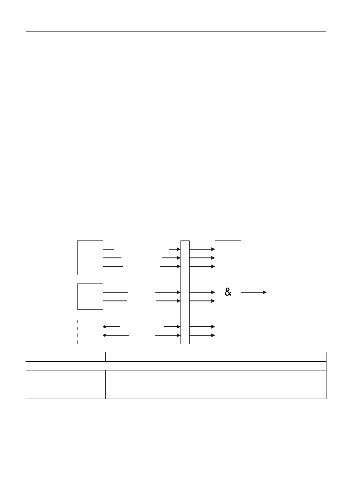
4.1.3 Checking the energy-saving states
The following signals are checked when entering or retaining the energy-saving profile. The
signals can be masked for each energy-saving profile.
Signal Function
Generated by the HMI
Keyboard has been used
(state condition "No key press‐
ed on the operator panel")
42 System Manual, 01/2015, 6FC5397-0EP40-5BA2
This signal is set if in the last second the keyboard of the SINUMERIK control was used.
This signal is only available once for each control system and is automatically linked through
the masking. In the case of several operator panels, the group signal of all keyboards is
used. For a keystroke, the HMI sets this bit and the PLC handles the reset process.
Ctrl-Energy
Page 43

Signal Function
Data transfer active
(state condition "No communi‐
cation with an external device
active (USB, Ethernet, V24)")
Screen change active
(state condition "No screen
change realized")
Generated by the PLC basic program (828D: PLC firmware)
Machine control panel used
(state condition "No key press‐
ed on the machine control pan‐
el")
NCK activity
(state condition "NC channel/
channels in reset")
From the PLC user program interface
Master computer prohibits
(state condition "master com‐
puter signal prohibits")
PLC user program signal
(state condition "PLC user sig‐
nal prohibits")
This signal is set if data is being transferred. After completion of the data transfer, the HMI
resets this bit. This includes the use of a USB memory medium, a V24 connection or a
network drive.
This signal is also set when generating or importing a commissioning archive. This signal
is only available once for each control system and is automatically linked through the mask‐
ing. In the case of several operating stations, the group signal is formed. Acyclic S7 com‐
munication in the sense of a connected engineering system or an external HMI does not
apply as data transfer in the sense of this signal.
This signal is set if a screen is being changed. After processing, the PLC resets the bit.
This signal is only available once for each control system and is automatically linked through
the masking. For several operator stations, the group signal is formed here.
This signal is set if the machine control panel in the PLC is used. To do this, a specified
address range of the inputs is monitored in the PLC.
● For 840D sl, the ranges addressed via parameters DB7 MCP1In and MCP2IN
● For 828D, the input range of the PN-MCP
This signal is only available once for each control system and is automatically linked through
the masking. The group signal is formed when several machine control panels are being
used.
This signal is set if the NCK channel is not in the Reset channel state.
Note: Static synchronized actions, which are also active in the Reset channel state = TRUE,
are not detected and must be taken into account by the user.
Using this signal, an external master computer or a coupled control system can prevent
that the energy-saving profile is activated. This signal is available in the user interface for
each energy-saving profile.
Using this signal, from the user program in the PLC, an energy-saving profile can be pre‐
vented from being activated. This signal is available in the user interface for each energysaving profile.
Ctrl-E Profiles
4.1 Commissioning the PLC for Ctrl-E Profiles
4.1.4 PLC user program
The following signals are available in the user program for controlling the energy-saving
profiles. These signals are not masked within the energy profile, and are available for each
profile.
Signal Function
Control signal to "directly acti‐
vate the energy-saving profile"
Set time to prewarning limit When setting this signal, the timer for the prewarning limit T2 is set to its setpoint and is
Ctrl-Energy
System Manual, 01/2015, 6FC5397-0EP40-5BA2 43
The energy-saving profile is immediately activated when this signal is set. The two timers
are set to zero. For the case that the energy profile has already been activated, no change
is made.
then restarted. This is also the case, even if the energy-saving profile is already active. The
activation is then reset, and after the prewarning time is set again.
Page 44
Ctrl-E Profiles
4.1 Commissioning the PLC for Ctrl-E Profiles
Signal Function
Feedback signal, "prewarning
time T1 expired"
Feedback signal, "prewarning
time T2 expired"
This signal is set by the basic PLC program (FB15) if the timer has expired and the pre‐
warning is output on the HMI.
This signal is set by the basic PLC program (FB15) if, after the prewarning limit has been
reached, also the prewarning time of the corresponding energy profile has expired. This
means that this signal is equivalent to the information "Energy-saving state active".
Note
Shutdown auxiliary equipment
If auxiliary equipment is also to be shut down using the "Prewarning time expired" signal, which
acknowledges the shutdown process, then using a normal PLC timer and the signal "PLC user
program signal", a monitoring function can be installed in the basic PLC program. If the auxiliary
equipment has still not been run down after the PLC timer has expired, then the energy-saving
state can be exited again using the "PLC user program signal".
4.1.5 Interface signals 840D sl
4.1.5.1 Signals for controlling energy-saving profiles
Dynamic data are cleared when the control powers up.
The signals described in the following section refer to energy-saving profile 1.
Control signals (user program)
DB1000
DBX0.0 Directly activate energy-saving profile
DBX0.1 Set time to prewarning limit
Control signals (HMI)
DB1000
DBX1.0 Directly activate energy-saving profile
Signals to check the energy-saving state (user program)
DB1000
DBX2.0 Master computer prohibits energy-saving state
DBX2.1 PLC user program signal prohibits energy-saving state
Ctrl-Energy
44 System Manual, 01/2015, 6FC5397-0EP40-5BA2
Page 45
Status signals
DB1000
DBX4.0 Energy-saving profile is active
DBX4.1 Prewarning limit T1 reached
Actual values
DB1000
DBW6 Actual value T
DBW8 Actual value T
4.1.5.2 Signals for parameterization
Retentive parameterization data.
Effectiveness (HMI → PLC)
Ctrl-E Profiles
4.1 Commissioning the PLC for Ctrl-E Profiles
1
2
DB1000
DBX 10.0 Energy-saving profile configured
DBX 10.1 Disable energy-saving profile
Masking (HMI → PLC)
DB1000
DBX 11.0 Keyboard has been used
DBX 11.1 Data transfer active
DBX 11.2 Screen change active
DBX 12.0 Machine control panel used
DBX 13.0 NCK channel 1
DBX 13.1 NCK channel 2
DBX 13.2 NCK channel 3
DBX 13.3 NCK channel 4
DBX 13.4 NCK channel 5
DBX 13.5 NCK channel 6
DBX 13.6 NCK channel 7
DBX 13.7 NCK channel 8
DBX 14.0 NCK channel 9
DBX 14.1 NCK channel 10
DBX 15.0 Master computer prohibits*
DBX 15.1 PLC user program signal prohibits*
*prohibits changing into the energy-saving mode
Ctrl-Energy
System Manual, 01/2015, 6FC5397-0EP40-5BA2 45
Page 46
Ctrl-E Profiles
4.1 Commissioning the PLC for Ctrl-E Profiles
Maximum times (HMI → PLC)
DB1000
DBW 16 Activation time T
DBW 18 Time for the prewarning limit T
Additional profile instances
DB1000
DBW 20 Energy-saving profile 2
DBW 40 Energy-saving profile 3
DBW 60 Energy-saving profile 4
DBW 80 Energy-saving profile 5
DBW 100 Energy-saving profile 6
DBW 120 Energy-saving profile 7
DBW 140 Energy-saving profile 8
1
2
4.1.6 Interface signals 828D
4.1.6.1 Signals for controlling energy-saving profiles
Dynamic data are cleared when the control powers up.
Control signals (user program)
DB9906
DBX0.0 Directly activate energy-saving profile
DBX0.1 Set time to prewarning limit
Control signals (HMI)
DB9906
DBX1.0 Directly activate energy-saving profile
Signals to check the energy-saving profile (user program)
DB9906
DBX2.0 Master computer prohibits energy-saving state
DBX2.1 PLC user program signal prohibits energy-saving state
Ctrl-Energy
46 System Manual, 01/2015, 6FC5397-0EP40-5BA2
Page 47
Status signals
DB9906
DBX4.0 Energy-saving profile is active
DBX4.1 Prewarning limit T1 reached
Actual values
DB9906
DBW6 Actual value T
DBW8 Actual value T
4.1.6.2 Signals for parameterization
Retentive parameterization data.
Effectiveness (HMI → PLC)
Ctrl-E Profiles
4.1 Commissioning the PLC for Ctrl-E Profiles
1
2
DB9906
DBX10.0 Energy-saving profile configured
DBX 10.1 Disable energy-saving profile
Masking (HMI → PLC)
DB9906
DBX11.0 Keyboard has been used
DBX11.1 Data transfer active
DBX11.2 Screen change active
DBX12.0 Machine control panel used
DBX13.0 NCK channel 1
DBX13.1 NCK channel 2
DBX15.0 Master computer prohibits*
DBX15.1 PLC user program signal prohibits*
*prohibits changing into the energy-saving mode.
Maximum times (HMI → PLC)
DB9906
DBW16 Activation time T
DBW18 Time for the prewarning limit T
1
2
Ctrl-Energy
System Manual, 01/2015, 6FC5397-0EP40-5BA2 47
Page 48

Ctrl-E Profiles
4.2 Creating and editing energy-saving profiles
Additional instances
DB9906
DBW20 Energy profile 2
DBW40 Energy profile 3
DBW60 Energy profile 4
DBW80 Energy profile 5
DBW100 Energy profile 6
DBW120 Energy profile 7
DBW140 Energy profile 8
4.2 Creating and editing energy-saving profiles
You can make the following changes in the list of energy-saving profiles in the commissioning
mode:
● Creating new energy-saving profiles with prewarning time and activation time period.
● Changing state conditions, prewarning time and activation time period
● Deleting energy-saving profiles
● Importing externally generated energy-saving profiles into the system
● Backing up energy-saving profiles on an external medium
Note
Maximum number of energy-saving profiles
A maximum of 8 energy-saving profiles can be created.
If the maximum number of profiles already exists, then the "New" softkey is no longer
available. To create a new energy-saving profile, remove a profile using the "Delete" softkey
or change an existing profile using the "Change" softkey.
Note
Access level of the energy-saving profiles for users
You specify the access level for the "Energy-saving profiles" softkey in the "Parameter"
operating area using the machine data 51071 $MNS_ ACTIVATE_CTRL_E (protection level
1 as standard; this must be explicitly enabled by the manufacturer).
Note
Designations of energy-saving profiles that have been created
The names of the new energy-saving profiles that have been created are only visible at the
control where you generated them.
Ctrl-Energy
48 System Manual, 01/2015, 6FC5397-0EP40-5BA2
Page 49

Energy conditions
Ctrl-E Profiles
4.2 Creating and editing energy-saving profiles
The following criteria are available for configuring an energy-saving profile:
State conditions Meaning
No key on the operator panel pressed To activate the energy-saving profile, it is not permis‐
sible that an operator panel key is pressed.
No key on the machine control panel pressed To activate the energy-saving profile, it is not permis‐
sible that a machine control panel key is pressed.
No screen change realized To activate the energy-saving profile it is not permis‐
sible that a screen is being changed.
No communication with an external device ac‐
tive (USB, Ethernet, V24)
NC channel/channels in Reset To activate the energy-saving profile, NC channel/
Master computer signal prohibits To activate the energy-saving profile, it is not permis‐
PLC user signal prohibits To activate the energy-saving profile, it is not permis‐
Activation of the energy-saving profile after Here, you enter the time period after which the ener‐
Prewarning after Here, you enter when the system starts to display the
To activate the energy-saving profile, it is not permis‐
sible that data is being exchanged with an external
device, for example.
channels must be in the Reset state.
sible that a signal is received from the master com‐
puter.
sible that a signal is received from the PLC user pro‐
gram.
The OEM can logically combine other state condi‐
tions with this signal and influence the profiles.
gy-saving profile is activated.
prewarning.
Note:
If you enter the same value into the "Activation of the
energy-saving profile after" and "Prewarning after"
fields, then no message is displayed specifying the
remaining time up until the energy-saving profile is
activated.
Note
Protection levels for editing energy-saving profiles
You define the protection level that is required in order to create or edit an energy-saving profile
in machine data 51072 $MNS_ACCESS_EDIT CTRL_E (default, protection level 2 (service)).
Ctrl-Energy
System Manual, 01/2015, 6FC5397-0EP40-5BA2 49
Page 50
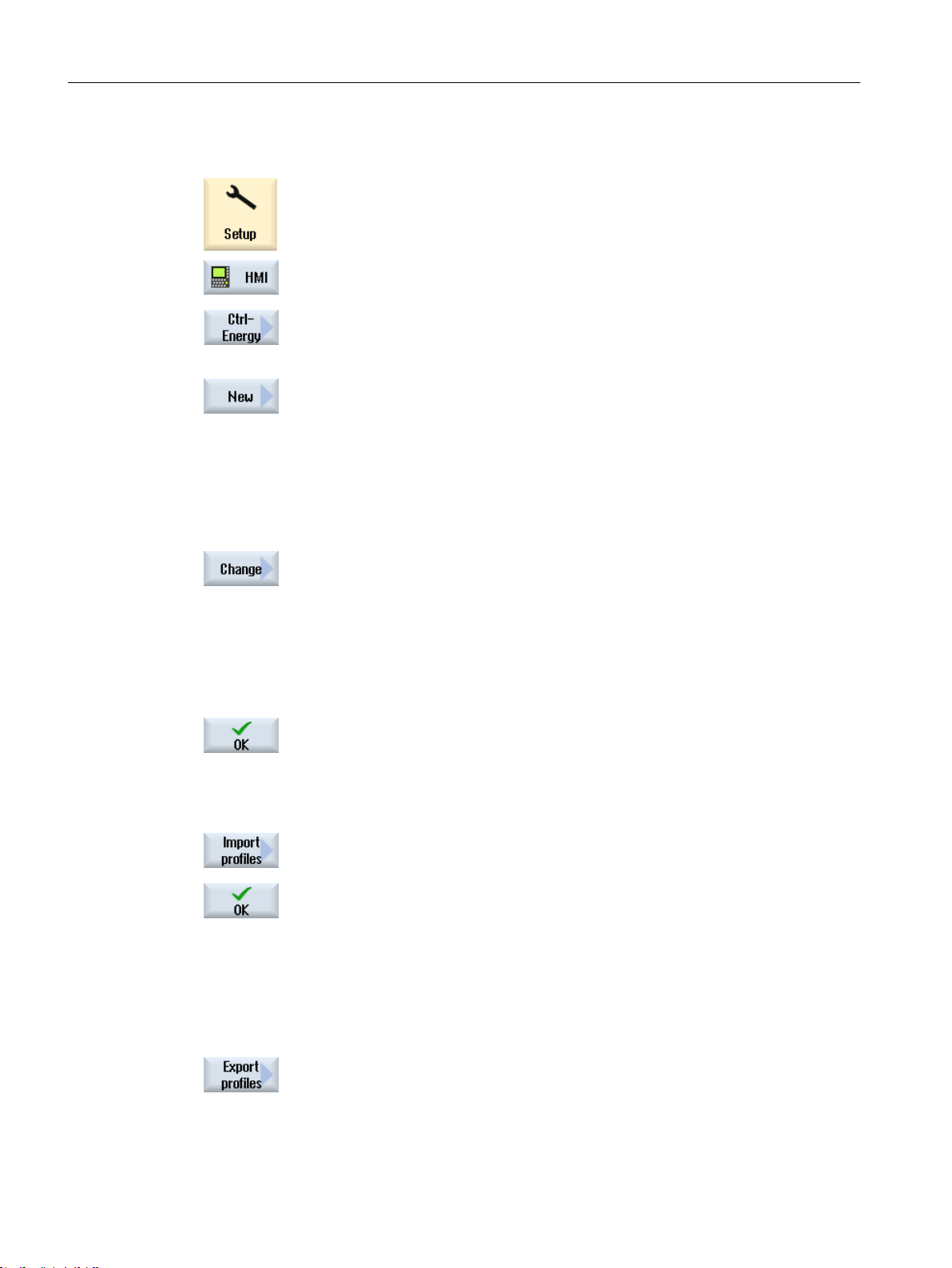
Ctrl-E Profiles
4.2 Creating and editing energy-saving profiles
Procedure
1. Select the "Startup" operating area.
2. Press the "HMI" and "Ctrl-Energy" softkeys.
The window "SINUMERIK Ctrl-Energy: Definition of the energy-saving
profile" is opened.
Newly creating/changing energy profiles
3. Position the cursor on the line where you wish to create a new energysaving profile and press the "New" softkey.
The window "SINUMERIK Ctrl-Energy: Definition of the energy-saving
profile" is opened.
In the "Designation" field, enter the desired name for the new energysaving profile. Activate the required state conditions. Specify the times to
display the prewarning limit and to activate the energy-saving profile.
- OR Position the cursor on the energy-saving profile that you want to edit and
press the "Change" softkey.
The window "SINUMERIK Ctrl-Energy: Definition of the energy-saving
profile" is opened.
In the "Designation" entry field, enter the modified name of the energy-
saving profile. Select or deselect the state conditions that should be ef‐
fective for the modified energy-saving profile - and when required, change
the time data.
4. Press the "OK" softkey.
The new or modified energy-saving profiles are activated.
The modified texts (def_conditions<long>.ts) are saved in the \oem\sinu‐
merik\hmi\lng directory.
Importing energy-saving profiles
5. Press the "Import profile" softkey.
The "Import energy-saving profiles" window is displayed.
Select the required XML file and press the "OK" softkey. After a prompt,
the energy-saving profiles are downloaded into the PLC.
The associated text files (def_conditions<long>.ts) are saved in the \oem
\sinumerik\hmi\lng directory.
Note:
After importing the energy-saving profiles, a restart is required in order
to make the profiles effective.
Exporting energy-saving profiles
6. Press the "Export profiles" softkey.
The window "Export energy-saving profiles: Select storage location"
opens.
Ctrl-Energy
50 System Manual, 01/2015, 6FC5397-0EP40-5BA2
Page 51

7. Select the required storage location and press the "OK" softkey.
The language-neutral state data are stored in the XML format, the asso‐
ciated texts in a .ts file. You have the option of selecting a name for the
XML file (default: def_conditions.xml).
The text files are saved under a fixed name. All of the defined energysaving profiles are always exported.
Note:
Please note that the energy-saving profiles supplied from Siemens are
also deleted. It is recommended that the energy-saving profiles are al‐
ways exported and backed up.
Deleting energy-saving profiles
8. Select the energy-saving profile that you want to delete from the list and
press the "Delete" softkey.
9. Confirm the prompt with "OK" to remove the profile.
Ctrl-E Profiles
4.2 Creating and editing energy-saving profiles
Ctrl-Energy
System Manual, 01/2015, 6FC5397-0EP40-5BA2 51
Page 52

Ctrl-E Profiles
4.2 Creating and editing energy-saving profiles
Ctrl-Energy
52 System Manual, 01/2015, 6FC5397-0EP40-5BA2
Page 53
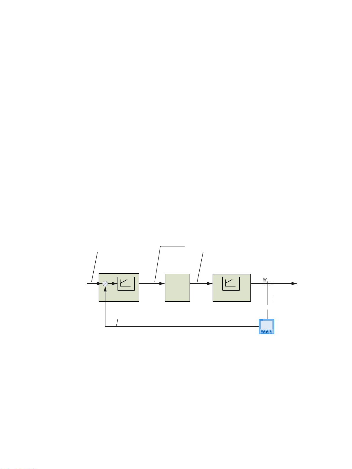
Reactive power compensation
7UDQVSRUW
D[LV
&XUUHQW
9ROWDJH
5HDFWLYHSRZHU4EDVLFIXQGDPHQWDO
$FWXDOYDOXH
5HDFWLYHSRZHU4EDVLFIXQGDPHQWDO
6HWSRLQW
6XSSOHPHQWDU\UHDFWLYHSRZHUVHWSRLQW
DVDSHUFHQWDJH
3KDVH
VKLIWHU
352),%86352),1(7
6(17521
3$&
3/&$/0
6)%
)%
3/&*3
*HW3XW
%,&2
The Active Line Modules of the SINAMICS S120 series offer the option of compensating
capacitive or inductive reactive current. As standard, this function is used to compensate for
the system's own modules.
In addition, within a sensible scope, this feature can be used to compensate other (generally
inductive) loads connected to machine.
As a result of the properties of the SINAMICS S120 Active Line Module as actuator on one
hand, the properties of SENTRON PAC4200 as measuring element as well as additional PLC
blocks (also as controller), this function can be implemented with the SINUMERIK 840D sl also
independent of NC software releases.
Further information
Please contact your local sales organization if you require additional information regarding
reactive power compensation.
Function schematic
5
Ctrl-Energy
System Manual, 01/2015, 6FC5397-0EP40-5BA2 53
Figure 5-1 Principle of operation of reactive power compensation
Page 54

Reactive power compensation
Ctrl-Energy
54 System Manual, 01/2015, 6FC5397-0EP40-5BA2
Page 55

Flux reduction
In the drive parameters (p1581 [0..n]), the rated magnetization for induction motors – which is
normally 100% – can be permanently reduced. This includes the switching times for reducing
and building up the flux (r1578, r1579[0…n]).
In this case, not only can the magnetizing losses in the motors be reduced at standstill, but
also during operations that only require a lower power.
Optimization criterion
Under no-load conditions, the percentage value of the rated magnetization is reduced in steps
of between 5-10% to just above a value where the no-load behavior starts to become uneven.
From this limit value onwards, rough operating behavior can be heard as a result of the
significantly fluctuating active current.
It makes sense to monitor the current characteristic and this transition point using a trace
function.
Options for use
You have various options to specifically use this.
6
● Permanently set the actual parameter set p1581 [0] to the determined value <100%.
Taking into consideration the time constants, the flux is automatically reduced if the
instantaneous active power permits this. If more active power is demanded, then the flex
automatically increases back up to 100% with the corresponding time constant. This does
not have a negative impact on the process.
● Preselecting various parameter sets
If load changes are to be expected in a time shorter than the time constant (e.g. for an
interrupted roughing cut with facing head milling tools), it may be more favorable for the
process if the flux is permanently controlled by pre-selecting various parameter sets by
knowing the machining to be expected or the tool involved.
Example ((see the interface signals at the spindle DB31-61.DBB21))
Bit0: = 0:
p1581 [0] = 100%;
p1578 [0] and p1579 [0] = factory setting, e.g. for an interrupted cut
Bit0: = 1:
p1581 [1] < 100%;
p1578 [1], p1579 [1], adapted for partial load or no load
Ctrl-Energy
System Manual, 01/2015, 6FC5397-0EP40-5BA2 55
Page 56

Flux reduction
Ctrl-Energy
56 System Manual, 01/2015, 6FC5397-0EP40-5BA2
Page 57

User know-how
Machine manufacturers are being increasingly confronted with special demands from users
regarding proving energy consumption data or displaying limit values, for example.
Using SINUMERIK Integrate Run MyScreens (Easy Screen), it is possible to visualize the
functions obtained from these requirements, and also position them in the context of CtrlEnergy.
Displaying additional measuring data
The SENTRON PAC 3200/4200 Power Monitoring Devices provide, in different expansion
stages, a wealth of electrical measured data.
In addition to the active power/active energy displayed today in SINUMERIK Operate, using
Easy Screen, you have the option of displaying, for example, the reactive power/reactive
energy and the apparent power/apparent energy of the measuring location in customized
screen forms.
References
More information on the various measuring options is available in the following references:
7
● SENTRON PAC3200 Power Monitoring Device Manual
● SENTRON PAC4200 Power Monitoring Device System Manual
7.1 Commissioning user screen forms
General procedure
● You create your own screen forms in SINUMERIK Integrate Run MyScreens (Easy Screen),
for example in a xxx.com file.
● You insert the new "xxx.com" project file name in "easyscreen.ini" in the "Parameter" area.
● Save the modified "easyscreen.ini" in the following directory: oem\sinumerik\hmi\cfg\.
● If the released horizontal softkey 7 in the extended softkey bar of the "Parameter" operating
area is already used with a "yyy.com", then you have the option of programming the vertical
softkey 4 behind the "Ctrl-Energy" softkey for an additional "xxx.com".
An additional neutral "aufruf.com" file is created with the following start softkeys:
//S(START)
VS4=("Start XXX")
Ctrl-Energy
System Manual, 01/2015, 6FC5397-0EP40-5BA2 57
Page 58

User know-how
7.1 Commissioning user screen forms
PRESS(VS4)
LM("maske_xxx","xxx.com")
END_PRESS
HS7=("Start YYY")
PRESS(HS7)
LM("maske_yyy","yyy.com")
END_PRESS
//END
These start calls directly access the specified screen forms of the relevant *.com files. A start
softkey in these particular *.com files can be omitted.
● Save the project files "xxx.com", "yyy.com" and "aufruf.com" in the following directory: oem
\sinumerik\hmi\proj\.
References
Additional information on the design and configuration of user interfaces is provided in the
following references on SINUMERIK Integrate Run MyScreens (Easy Screen):
Programming Manual Easy Screen (BE2); SINUMERIK 840D sl
Ctrl-Energy
58 System Manual, 01/2015, 6FC5397-0EP40-5BA2
Page 59

Appendix
A.1 Overview
A
Ctrl-Energy
System Manual, 01/2015, 6FC5397-0EP40-5BA2 59
Page 60
(OHFWURQLF'RFXPHQWDWLRQ
,QIR7UDLQLQJ
7UDLQLQJ'RFXPHQWV
ದ0LOOLQJPDGHHDV\
ZLWK6KRS0LOO
ದ7XUQLQJPDGHHDV\
ZLWK6KRS7XUQ
0DQXDO
7RRODQG
PROGPDNLQJ
*HQHUDO'RFXPHQWDWLRQ
6,180(5,.'LVO'RFXPHQWDWLRQ2YHUYLHZ
8VHU'RFXPHQWDWLRQ
0DQXIDFWXUHU6HUYLFH'RFXPHQWDWLRQ
0DQXIDFWXUHU6HUYLFH'RFXPHQWDWLRQ
6DOHV%URFKXUH&DWDORJ1&
&DWDORJ30b6,027,21
6,1$0,&6b6DQG0RWRUV
IRU3URGXFWLRQ0DFKLQHV
)XQFWLRQ0DQXDO
'ULYH)XQFWLRQV
)XQFWLRQ0DQXDO
6DIHW\,QWHJUDWHG
&RQILJXUDWLRQ0DQXDO
(0&,QVWDOODWLRQ
*XLGHOLQHV
0DQXDO
ದ1&8
ದ2SHUDWRU&RPSRQHQWV
DQG1HWZRUNLQJ
)XQFWLRQ0DQXDO
ದ%DVLF)XQFWLRQV
ದ([WHQGHG)XQFWLRQV
ದ6SHFLDO)XQFWLRQV
ದ6\QFKURQL]HG$FWLRQV
ದ,62'LDOHFWV
)XQFWLRQ0DQXDO
7RRO0DQDJHPHQW
2SHUDWLQJ0DQXDO
ದ8QLYHUVDO
ದ7XUQLQJ
ದ0LOOLQJ
3URJUDPPLQJ0DQXDO
ದ)XQGDPHQWDOV
ದ$GYDQFHG
ದ0HDVXULQJ&\FOHV
3URJUDPPLQJ0DQXDO
ದ,627XUQLQJ
ದ,620LOOLQJ
'LDJQRVWLFV0DQXDO
&RPPLVVLRQLQJ0DQXDO
ದ&1&1&.3/&
'ULYH
ದ%DVHVRIWZDUHDQG
2SHUDWLQJ6RIWZDUH
/LVW0DQXDO
ದ0DFKLQH'DWD
ದ,QWHUIDFH6LJQDOV
ದ9DULDEOHV
6\VWHP0DQXDO
*XLGHOLQHVIRUPDFKLQH
FRQILJXUDWLRQ
6\VWHP0DQXDO
&WUO(QHUJ\
,QGXVWU\0DOO
0\'RFXPHQWDWLRQ
0DQDJHU
'2&RQ&'
6,180(5,.6,180(5,.
6,180(5,.
'VO
6,180(5,.
'VO
'
6,180(5,.
'VO
'
6,180(5,.
'VO
'
6,1$0,&6
6
6,180(5,.
'VO
6,180(5,.
'VO
6,180(5,.
6,180(5,.
'VO
6,180(5,.
'VO
'
6,180(5,.
'VO
6,180(5,.
'VO
6,180(5,.
'VO
6,180(5,.
'VO
6,180(5,.
'VO
'
6,1$0,&6
6
6,1$0,&6
6
6,1$0,&6
6
Appendix
A.1 Overview
60 System Manual, 01/2015, 6FC5397-0EP40-5BA2
Ctrl-Energy
Page 61

Index
C
Commissioning HMI, 39
Configuring
Energy-saving profiles, 48
Ctrl Energy
Functions, 9
E
Energy consumption
display in status line, 38
Energy-saving profiles, 39
Edit, 48
H
Hardware, 12
P
PLC functions, 40
PLC user program, 43
Power Monitoring Device
Commissioning, 13
PROFIBUS
Commissioning the PLC (840D sl), 15
S
SENTRON PAC3200/4200
Commissioning the PLC (840D sl), 15, 19
Parameterizing, 14
Profibus (840D sl), 15
Status bar
Displaying energy consumption, 38
Ctrl-Energy
System Manual, 01/2015, 6FC5397-0EP40-5BA2 61
Page 62

Index
Ctrl-Energy
62 System Manual, 01/2015, 6FC5397-0EP40-5BA2
 Loading...