

Siemens SINUMERIK 840DE, SINUMERIK 840D, SINUMERIK 840Di, SINUMERIK 840DiE, SINUMERIK 810D Programming Manual
...Page 1

Programming Manual 10/2004 Edition
SINUMERIK 840D/840Di/810D
Fundamentals
Page 2

Page 3

A
SINUMERIK 840D/840Di/810D
Fundamentals
Programming Manual
Preface
Fundamental Geometrical
Principles
Fundamental Principles of
NC Programming
Positional Data
Programming Motion
Commands
Path Action
Frames
1
2
3
4
5
6
pplicable to
the following controls:
SINUMERIK 840D powerline
SINUMERIK 840DE powerline (export version)
SINUMERIK 840Di
SINUMERIK 840DiE (export version)
SINUMERIK 810D powerline
SINUMERIK 810DE powerline (export version)
software version
NC 7
Feedrate Control and
Spindle Motion
Tool offsets
Special functions
Arithmetic Parameters and
Program Jumps
Subprograms and Repetition
of Program Sections
Tables
List of abbreviations
7
8
9
10
11
12
A
10.2004 Edition
6FC5 298-7AB00-0BP1
Page 4

Safety Guidelines
This manual contains notices you have to observe in order to ensure your personal safety, as well as to prevent
damage to property. The notices referring to your personal safety are highlighted in the manual by a safety alert
symbol, notices referring to property damage only have no safety alert symbol. These notices shown below are
graded according to the degree of danger.
Danger
indicates that death or severe personal injury will result if proper precautions are not taken.
Warning
indicates that death or severe personal injury may result if proper precautions are not taken.
Caution
with a safety alert symbol, indicates that minor personal injury can result if proper precautions are not taken.
Caution
without a safety alert symbol, indicates that property damage can result if proper precautions are not taken.
Notice
indicates that an unintended result or situation can occur if the corresponding information is not taken into
account.
If more than one degree of danger is present, the warning notice representing the highest degree of danger will
be used. A notice warning of injury to persons with a safety alert symbol may also include a warning relating to
property damage.
Qualified Personnel
The device/system may only be set up and used in conjunction with this documentation. Commissioning and
operation of a device/system may only be performed by qualified personnel. Within the context of the safety notes
in this documentation qualified persons are defined as persons who are authorized to commission, ground and
label devices, systems and circuits in accordance with established safety practices and standards.
Prescribed Usage
Note the following:
Warning
This device may only be used for the applications described in the catalog or the technical description and only in
connection with devices or components from other manufacturers which have been approved or recommended
by Siemens. Correct, reliable operation of the product requires proper transport, storage, positioning and
assembly as well as careful operation and maintenance.
Trademarks
All names identified by ® are registered trademarks of the Siemens AG. The remaining trademarks in this
publication may be trademarks whose use by third parties for their own purposes could violate the rights of the
owner.
Copyright Siemens AG . All rights reserved.
The distribution and duplication of this document or the utilization and transmission of its
contents are not permitted without express written permission. Offenders will be liable for
damages. All rights, including rights created by patent grant or registration of a utility
model or design, are reserved.
Siemens AG
Automation and Drives
Postfach 4848, 90327 Nuremberg, Germany
Siemens Aktiengesellschaft 6FC5 298-7AB00-0BP1
Disclaimer of Liability
We have reviewed the contents of this publication to ensure consistency with the
hardware and software described. Since variance cannot be precluded entirely, we cannot
guarantee full consistency. However, the information in this publication is reviewed
regularly and any necessary corrections are included in subsequent editions.
Siemens AG 2005
Technical data subject to change
Page 5

Preface
Structure of the documentation
The SINUMERIK documentation is organized in 3 parts:
• General documentation
• User documentation
• Manufacturer/service documentation
Audience
This document is designed for machine tool users. The document describes in detail all the
technical facts an operator needs to understand how to program the SINUMERIK
840D/810D control systems.
Standard scope
This Programming Guide describes the functionality afforded by standard functions.
Extensions or changes made by the machine tool manufacturer are documented by the
machine tool manufacturer.
Please contact your local Siemens office for more detailed information about other
SINUMERIK 840D/810D publications and publications that apply to all SINUMERIK controls
(e.g., universal interface, measuring cycles, etc.).
Other functions not described in this documentation might be executable in the control. This
does not, however, represent an obligation to supply such functions with a new control or
when servicing.
Validity
This Programming Guide applies to the following controls:
SINUMERIK 840D powerline 7
SINUMERIK 840DE powerline (export version) 7
SINUMERIK 840Di 3
SINUMERIK 840DiE (export version) 3
SINUMERIK 810D powerline 7
SINUMERIK 810DE powerline (export version)
with operator panels OP 010, OP 010C, OP 010S, OP 12,
or OP 15 (PCU 20 or PCU 50)
7
Fundamentals
Programming Manual, 10.2004 Edition, 6FC5 298-7AB00-0BP1
iii
Page 6

Preface
Export version
The following functions are not available in the export version:
Function 810DE 840DE
Five axis machining package − −
Handling transformation package (five axes) − −
Multi-axis interpolation (> four axes) − −
Helical interpolation 2D+6 − −
Synchronized actions, stage 2 − O1)
Measurements, stage 2 − O1)
Adaptive control − O1)
Continuous dressing − O1)
Utilization of compile cycles (OEM) − −
Sag compensation, multi-dimensional − O1)
− function not available
1) limited functionality
Hotline and Internet address
If you have any questions, please get in touch with our hotline:
Description
A&D Technical Support
Phone: +49 (0)180 50 50 222
Fax: +49 (0)180 50 50 223
Please send any queries about the documentation (suggestions or corrections) to the
following fax number or email address:
Fax: +49 (0)9131 98 21 76
E-mail: [email protected]
Fax form: See the reply form at the end of the document.
Fundamentals
This Programming Guide "Fundamentals" is intended for use by skilled machine operators
with the appropriate expertise in drilling, milling and turning operations. Simple programming
examples are used to explain the commands and statements, which are also defined
according to DIN 66025.
Job planning
The Programming Guide "Advanced" is intended for use by technicians with in-depth,
comprehensive programming knowledge. By virtue of a special programming language, the
SINUMERIK 840D/810D control enables the user to program complex workpiece programs
(e.g., for sculptured surfaces, channel coordination, etc.) and greatly facilitates the
programming of complicated operations.
Fundamentals
iv Programming Manual, 10.2004 Edition, 6FC5 298-7AB00-0BP1
Page 7

Preface
The commands and statements described in this Guide are not specific to one particular
technology.
They could be used, for example, for the following:
• Grinding
• Cyclical machines (packaging, woodworking)
• Laser power controls
Fundamentals
Programming Manual, 10.2004 Edition, 6FC5 298-7AB00-0BP1
v
Page 8

Page 9

Table of contents
Preface ......................................................................................................................................................iii
1 Fundamental Geometrical Principles ......................................................................................................1-1
1.1 Description of workpiece points ................................................................................................. 1-1
1.1.1 Workpiece coordinate systems.................................................................................................. 1-1
1.1.2 Definition of workpiece positions................................................................................................ 1-2
1.1.3 Polar coordinates ....................................................................................................................... 1-5
1.1.4 Absolute dimensions.................................................................................................................. 1-5
1.1.5 Incremental dimension............................................................................................................... 1-7
1.1.6 Plane designations..................................................................................................................... 1-8
1.2 Position of zero points.............................................................................................................. 1-10
1.3 Position of coordinate systems ................................................................................................ 1-11
1.3.1 Overview of various coordinate systems ................................................................................. 1-11
1.3.2 Machine coordinate system ..................................................................................................... 1-12
1.3.3 Basic coordinate system .......................................................................................................... 1-15
1.3.4 Workpiece coordinate system.................................................................................................. 1-17
1.3.5 Frame system .......................................................................................................................... 1-18
1.3.6 Assignment of workpiece coordinate system to machine axes ............................................... 1-20
1.3.7 Current workpiece coordinate system ..................................................................................... 1-21
1.4 Axes ......................................................................................................................................... 1-22
1.4.1 Main axes/Geometry axes ....................................................................................................... 1-23
1.4.2 Special axes............................................................................................................................. 1-24
1.4.3 Main spindle, master spindle ................................................................................................... 1-24
1.4.4 Machine axes ........................................................................................................................... 1-24
1.4.5 Channel axes ........................................................................................................................... 1-25
1.4.6 Path axes ................................................................................................................................. 1-25
1.4.7 Positioning axes....................................................................................................................... 1-25
1.4.8 Synchronized axes................................................................................................................... 1-26
1.4.9 Command axes........................................................................................................................ 1-27
1.4.10 PLC axes...............................................................................................................
1.4.11 Link axes .................................................................................................................................. 1-27
1.4.12 Lead link axes .......................................................................................................................... 1-28
1.5 Coordinate systems and workpiece machining ....................................................................... 1-30
2 Fundamental Principles of NC Programming.......................................................................................... 2-1
2.1 Structure and contents of an NC program ................................................................................. 2-1
2.2 Language elements of the programming language ................................................................... 2-2
2.3 Programming a sample workpiece........................................................................................... 2-21
2.4 First programming example for milling application .................................................................. 2-22
2.5 Second programming example for milling application ............................................................. 2-23
2.6 Programming example for turning application ......................................................................... 2-26
................... 1-27
Fundamentals
Programming Manual, 10.2004 Edition, 6FC5 298-7AB00-0BP1
vii
Page 10

Table of contents
3 Positional Data........................................................................................................................................ 3-1
3.1 General notes............................................................................................................................. 3-1
3.1.1 Program dimensions .................................................................................................................. 3-1
3.2 Absolute/relative dimensions ..................................................................................................... 3-2
3.2.1 Absolute dimension (G90, X=AC) .............................................................................................. 3-2
3.2.2 Incremental dimensions (G91, X=IC)......................................................................................... 3-6
3.3 Absolute dimension for rotary axes (DC, ACP, ACN) .............................................................. 3-10
3.4 Dimensions inch/metric, (G70/G700, G71/G710) .................................................................... 3-12
3.5 Special turning functions .......................................................................................................... 3-15
3.5.1 Dimensions for radius, diameter, (DIAMON, DIAMOF, DIAM90) ............................................ 3-15
3.5.2 Position of workpiece ............................................................................................................... 3-17
3.6 Zero offset (frame), G54 to G57, G505 to G599, G53, G500/SUPA ....................................... 3-19
3.7 Selection of working plane (G17 to G19) ................................................................................. 3-25
3.8 Working area limitation (G25/G26, WALIMON, WALIMOF) .................................................... 3-28
3.9 Reference point approach (G74) ............................................................................................. 3-32
4 Programming Motion Commands ........................................................................................................... 4-1
4.1 General notes............................................................................................................................. 4-1
4.2 Travel commands with polar coordinates, polar angle, polar radius ......................................... 4-4
4.2.1 Defining the pole (G110, G111, G112) ...................................................................................... 4-4
4.2.2 Traversing commands with polar coordinates, (G0, G1, G2, G3 AP=..., RP=...) ...................... 4-5
4.3 Rapid traverse movement (G0, RTLION, RTLIOF) ................................................................... 4-9
4.4 Linear interpolation (G1) .......................................................................................................... 4-14
4.5 Circular interpolation types, (G2/G3, CIP, CT)......................................................................... 4-16
4.6 Circular interpolation with center point and end point (G2/G3, I=, J=, K=AC...) ...................... 4-20
4.7 Circular interpolation with radius and end point (G2/G3, CR).................................................. 4-24
4.8 Circular interpolation with arc angle and center point (G2/G3, AR=)....................................... 4-26
4.9 Circular interpolation with polar coordinates (G2/G3, AP=, RP=)............................................ 4-28
4.10 Circular interpolation with intermediate and end points (CIP).................................................. 4-30
4.11 Circular interpolation with tangential transition (CT) ................................................................ 4-3
2
4.12 Helical interpolation (G2/G3, TURN=)...................................................................................... 4-36
4.13 Involute interpolation (INVCW, INVCCW)................................................................................ 4-38
4.14 Contour definitions ................................................................................................................... 4-43
4.14.1 Straight line with angle (X2... ANG...) ...................................................................................... 4-43
4.14.2 Two straight lines (ANG1, X3... Z3... ANG2) ........................................................................... 4-44
4.14.3 Three straight lines (ANG1, X3... Z3... ANG2, X4... Z4...) ....................................................... 4-45
4.14.4 End point programming with angle .......................................................................................... 4-47
4.15 Thread cutting with constant lead (G33) .................................................................................. 4-47
4.15.1 Programmable run-in and run-out paths (DITS, DITE) ............................................................ 4-54
4.16 Linear progressive/degressive thread pitch change (G34, G35) ............................................. 4-56
4.17 Tapping without compensating chuck (G331, G332)............................................................... 4-57
4.18 Tapping with compensating chuck (G63)................................................................................. 4-59
4.19 Stop with thread cutting(LFOF, LFON, LFTXT, LFWP, LFPOS) ............................................. 4-61
Fundamentals
viii Programming Manual, 10.2004 Edition, 6FC5 298-7AB00-0BP1
Page 11

Table of contents
4.19.1 Retraction for thread cutting (LFOF, LFON, LIFTFAST, DILF, ALF) ....................................... 4-61
4.19.2 Lifting on retraction (LFTXT, LFWP, LFPOS, POLF, POLFMASK; POLFMLIN)..................... 4-63
4.20 Approaching a fixed point (G75) .............................................................................................. 4-66
4.21 Travel to fixed stop (FXS, FXST, FXSW) ................................................................................ 4-67
4.22 Chamfer, rounding (CHF, CHR, RND, RNDM, FRC, FRCM) .................................................. 4-71
5 Path Action ............................................................................................................................................. 5-1
5.1 General notes............................................................................................................................. 5-1
5.1.1 Programming path travel behavior............................................................................................. 5-1
5.2 Exact stop (G60, G9, G601, G602, G603)................................................................................. 5-4
5.3 Continuous-path mode (G64, G641, G642, G643, G644) ......................................................... 5-7
5.4 Acceleration behavior .............................................................................................................. 5-15
5.4.1 Acceleration response, BRISK, SOFT, DRIVE........................................................................ 5-15
5.4.2 Influence of acceleration on following axes (VELOLIMA, ACCLIMA, JERKLIMA).................. 5-17
5.4.3 Technology G groups (DYNNORM, DYNPOS, DYNROUGH, DYNSEMIFIN, DYNFISH)...... 5-19
5.5 Smoothing the path velocity..................................................................................................... 5-20
5.6 Traversing with feedforward control, FFWON, FFWOF........................................................... 5-21
5.7 Contour accuracy, CPRECON, CPRECOF ............................................................................. 5-22
5.8 Dwell time, G4.......................................................................................................................... 5-24
5.9 Internal preprocessor stop ....................................................................................................... 5-25
6 Frames .................................................................................................................................................. 6-1
6.1 General ...................................................................................................................................... 6-1
6.2 Frame instructions ..................................................................................................................... 6-4
6.3 Programmable zero offset.......................................................................................................... 6-6
6.3.1 Zero offset (TRANS, ATRANS).................................................................................................. 6-6
6.3.2 Axial zero offset (G58, G59) .................................................................................................... 6-11
6.4 Programmable rotation (ROT, AROT, RPL) ............................................................................ 6-13
6.5 Programmable frame rotations with solid angles (ROTS, AROTS, CROTS) .......................... 6-24
6.6 Programmable scale factor (SCALE, ASCALE) ...................................................................... 6-25
6.7 Programmable mirroring (MIRROR, AMIRROR) ..................................................................... 6-29
6.8 Frame generation according to tool orientation (TOFRAME, TOROT, PAROT)..................... 6-34
6.9 Deselect frame (G53, G153, SUPA, G500) .....................
........................................................ 6-38
6.10 Deselect DRF (handwheel) offsets, overlaid motions and transformation (DRFOF, CORROF,
TRAFOOF)............................................................................................................................... 6-39
7 Feedrate Control and Spindle Motion ..................................................................................................... 7-1
7.1 Feedrate (G93, G94, G95 or F..., FGROUP, FGREF)............................................................... 7-1
7.2 Traversing positioning axes (POS, POSA, POSP, FA, WAITP, WAITMC) ............................... 7-9
7.3 Position-controlled spindle operation (SPCON, SPCOF) ........................................................ 7-11
7.4 Positioning spindles (position-controlled axis operation) (SPOS, M19 and SPOSA).............. 7-12
7.5 Milling on turned parts (TRANSMIT)........................................................................................ 7-19
7.6 Cylinder surface transformation (TRACYL) ............................................................................. 7-21
Fundamentals
Programming Manual, 10.2004 Edition, 6FC5 298-7AB00-0BP1
ix
Page 12

Table of contents
7.7 Feedrate for positioning axes/spindles (FA, FPR, FPRAON, FPRAOF) ................................. 7-23
7.8 Percentage feedrate override (OVR, OVRA) ........................................................................... 7-25
7.9 Feedrate with handwheel override (FD, FDA) ......................................................................... 7-26
7.10 Percentage acceleration override (ACC option) ...................................................................... 7-30
7.11 Feedrate optimization for curved path sections (CFTCP, CFC, CFIN).................................... 7-32
7.12 Spindle speed (S), direction of spindle rotation (M3, M4, M5)................................................. 7-34
7.13 Constant cutting rate (G96, G961, G97, G971, LIMS)............................................................. 7-37
7.14 Constant grinding wheel peripheral speed (GWPSON, GWPSOF)......................................... 7-41
7.15 Programmable spindle speed limitation (G25, G26) ................................................................ 7-42
7.16 Multiple feedrate values in one block (F.., ST=.., SR=.., FMA.., STA=.., SRA=..)................... 7-43
7.17 Blockwise feed (FB...) .............................................................................................................. 7-45
8 Tool offsets............................................................................................................................................. 8-1
8.1 General notes............................................................................................................................. 8-1
8.1.1 Tool offsets................................................................................................................................. 8-1
8.1.2 Tool offsets in the control's offset memory ................................................................................ 8-2
8.2 List of tool types ......................................................................................................................... 8-5
8.3 Tool selection/tool call T........................................................................................................... 8-12
8.3.1 Tool change with T commands (turning).................................................................................. 8-12
8.3.2 Tool change with M06 (mill) ..................................................................................................... 8-12
8.4 Tool offset D ............................................................................................................................. 8-15
8.5 Tool selection T with tool management ................................................................................... 8-17
8.5.1 Turning machine with circular magazine (T selection)............................................................. 8-18
8.5.2 Milling machine with chain magazine (T selection).................................................................. 8-19
8.6 Tool offset call D with tool management .................................................................................. 8-20
8.6.1 Turning machine with circular magazine (D call) ..................................................................... 8-20
8.6.2 Milling machine with chain magazine (D call) .......................................................................... 8-21
8.7 Activating the active tool offset immediately ............................................................................ 8-22
8.8 Tool radius compensation (G40, G41, G42) ............................................................................ 8-23
8.9 Contour approach and retraction (NORM, KONT, KONTC, KONTT)...................................... 8-32
8.10 Compensation at the outside corners (G450, G451) ............................................................... 8-38
8.11 Smooth approach and retraction.............................................................................................. 8-42
8.11.1 Approach and retraction (G140 to G143, G147, G148, G247, G248, G347, G348, G340, G341)
................................................................................................................................................. 8-42
8.11.2 Approach and retraction with enhanced retraction strategies (G460, G461, G462)................ 8-54
8.12 Collision monitoring (CDON, CDOF, CDOF2) ......................................................................... 8-58
8.13 2 ½ D tool offset (CUT2D, CUT2DF) ....................................................................................... 8-61
8.14 Tool length compensation for orientable toolholders (TCARR, TCOABS, TCOFR)................ 8-63
8.15 Grinding-specific tool monitoring in parts programs (TMON, TMOF) ...................................... 8-66
8.16 Additive offsets ......................................................................................................................... 8-68
8.16.1 Select offsets (via DL numbers)............................................................................................... 8-68
8.16.2 Specify wear and setup values ($TC_SCPxy[t,d], $TC_ECPxy[t,d]) ....................................... 8-69
8.16.3 Delete additive offsets (DELDL)............................................................................................... 8-70
8.17 Special handling of tool offsets ................................................................................................ 8-71
Fundamentals
x Programming Manual, 10.2004 Edition, 6FC5 298-7AB00-0BP1
Page 13

Table of contents
8.17.1 Mirroring of tool lengths ........................................................................................................... 8-73
8.17.2 Wear sign evaluation ............................................................................................................... 8-74
8.17.3 Coordinate system of the active machining operation
(TOWSTD/TOWMCS/TOWWCS/TOWBCS/TOWTCS/TOWKCS) ......................................... 8-75
8.17.4 Tool length and plane change.................................................................................................. 8-78
8.18 Tools with a relevant cutting edge length ................................................................................ 8-79
9 Special functions..................................................................................................................................... 9-1
9.1 Auxiliary function outputs ........................................................................................................... 9-1
9.1.1 M functions................................................................................................................................. 9-5
9.1.2 H functions ................................................................................................................................. 9-7
10 Arithmetic Parameters and Program Jumps ......................................................................................... 10-1
10.1 Arithmetic parameter (R).......................................................................................................... 10-1
10.2 Unconditional program jumps .................................................................................................. 10-3
10.3 Conditional program jumps (IF, GOTOB, GOTOF, GOTO, GOTOC) ..................................... 10-5
11 Subprograms and Repetition of Program Sections............................................................................... 11-1
11.1 Use of subprograms................................................................................................................. 11-1
11.2 Subprogram call ....................................................................................................................... 11-4
11.3 Subprogram with program repetition ....................................................................................... 11-6
11.4 Program section repetition ....................................................................................................... 11-7
12 Tables................................................................................................................................................... 12-1
12.1 List of statements ..................................................................................................................... 12-1
12.2 List of addresses .................................................................................................................... 12-22
12.3 List of G functions/preparatory functions ............................................................................... 12-30
12.4 List of predefined subprograms ............................................................................................. 12-44
12.4.1 Predefined subprogram calls ................................................................................................. 12-44
12.4.2 Predefined subprogram calls in motion-synchronous actions ............................................... 12-57
12.4.3 Predefined functions .............................................................................................................. 12-58
12.4.4 Data types ..............................................
................................................................................ 12-63
A List of abbreviations................................................................................................................................A-1
A.1 Abbreviations ............................................................................................................................. A-1
Glossary ..................................................................................................................................... Glossary-1
Index
Fundamentals
Programming Manual, 10.2004 Edition, 6FC5 298-7AB00-0BP1
xi
Page 14

Page 15
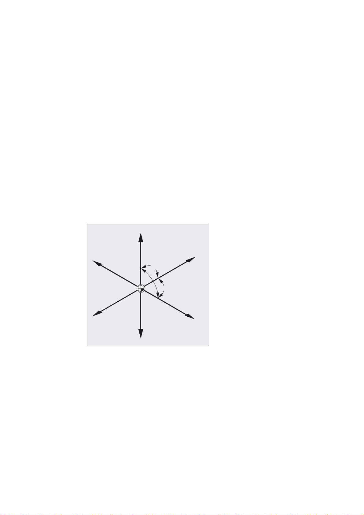
Fundamental Geometrical Principles
1.1 Description of workpiece points
1.1.1 Workpiece coordinate systems
In order for the machine or control to operate with the specified positions, these data must be
entered in a reference system that corresponds to the direction of motion of the axis slides. A
coordinate system with the axes X, Y and Z is used for this purpose.
Milling:
=
;
r
r
r
:
<
1
<
=
Fundamentals
Programming Manual, 10.2004 Edition, 6FC5 298-7AB00-0BP1
;
1-1
Page 16
Fundamental Geometrical Principles
1.1 Description of workpiece points
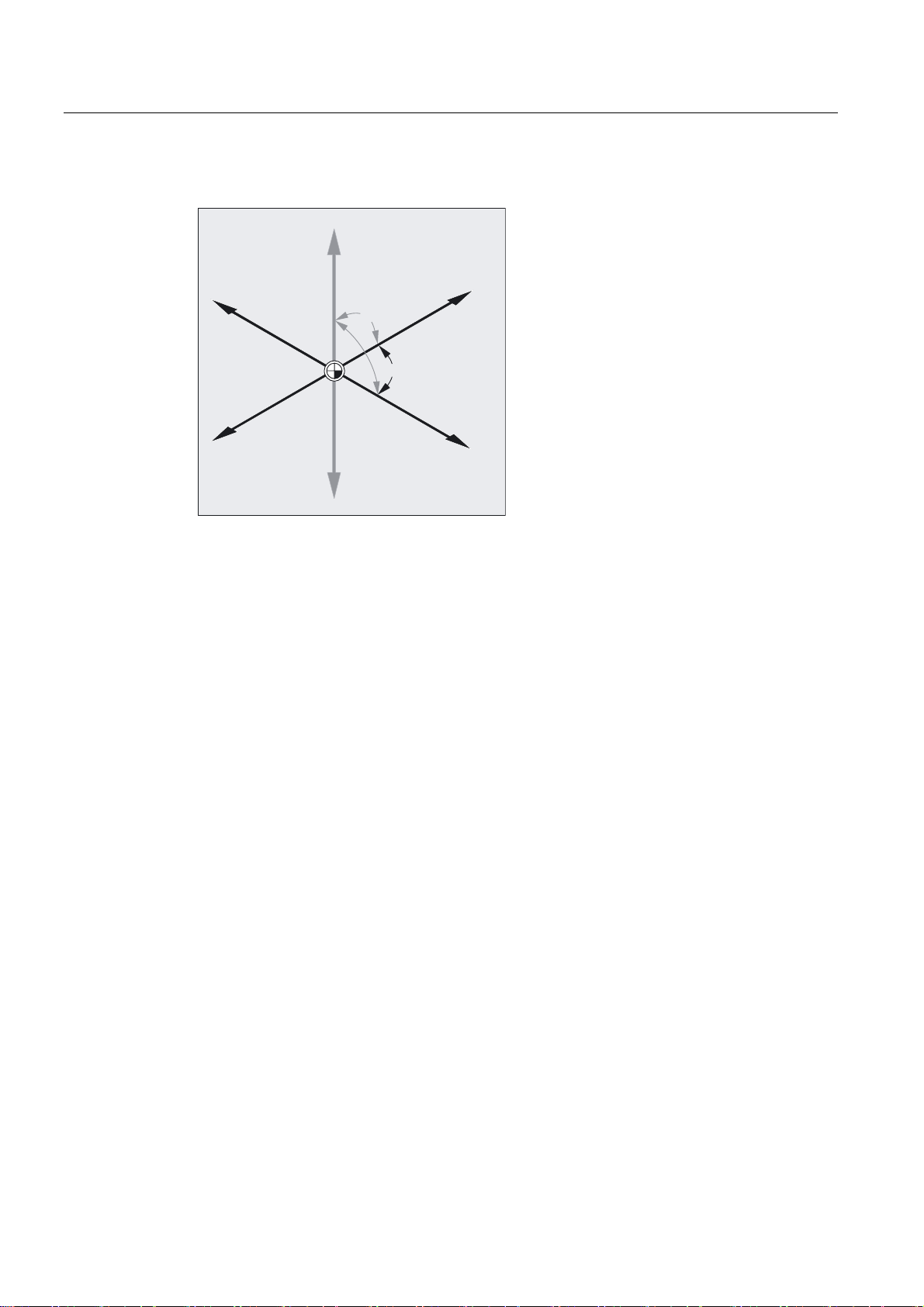
Turning:
<
=
r
r
r
:
;
<
DIN 66217 stipulates that machine tools must use right-handed, rectangular (Cartesian)
coordinate systems.
The workpiece zero (W) is the origin of the workpiece coordinate system. Sometimes it is
advisable or even necessary to work with negative positional data. Positions to the left of the
origin are prefixed by a negative sign (–).
1.1.2 Definition of workpiece positions
To specify a position, imagine that a ruler is placed along the coordinate axes. You can now
describe every point in the coordinate system by specifying the direction (X, Y and Z) and
three numerical values. The workpiece zero always has the coordinates X0, Y0, and Z0.
;
=
The infeed depth must also be described in milling operations.
One plane is sufficient to describe the contour on a lathe.
Workpiece positions in the working area
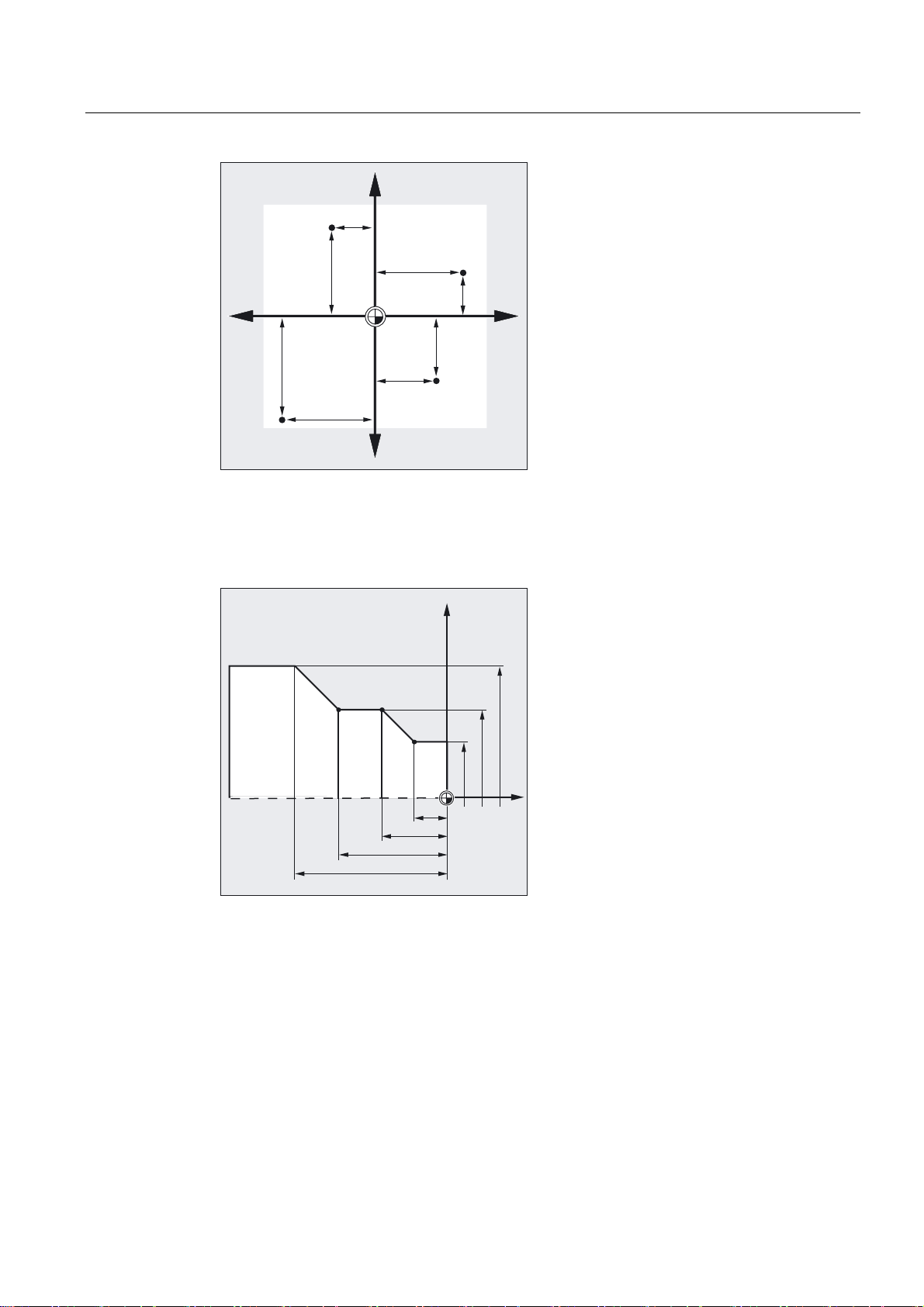
For the sake of simplicity, we will only use one plane of the coordinate system in this
example, i.e., the X/Y plane. Points P1 to P4 then have the following coordinates:
Fundamentals
1-2 Programming Manual, 10.2004 Edition, 6FC5 298-7AB00-0BP1
Page 17
Fundamental Geometrical Principles
1.1 Description of workpiece points
<
3
;
3
<
P1 corresponds to X100 Y50
P2 corresponds to X-50 Y100
P3 corresponds to X-105 Y-115
P4 corresponds to X70 Y-75
3
3 3
3
;
3
;
3
=
The workpiece positions are required only in one plane for turning.
Points P1 to P4 are defined by the following coordinates:
P1 corresponds to X25 Z-7.5
P2 corresponds to X40 Z-15
P3 corresponds to X40 Z-25
P4 corresponds to X60 Z-35
Fundamentals
Programming Manual, 10.2004 Edition, 6FC5 298-7AB00-0BP1
1-3
Page 18
Fundamental Geometrical Principles
1.1 Description of workpiece points
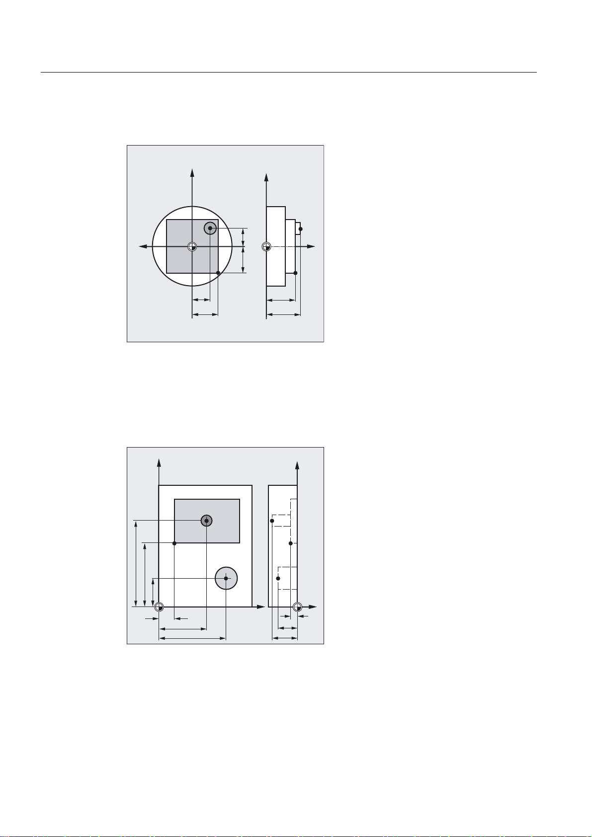
Example of turning positions
Points P1 and P2 are defined by the following coordinates:
;
<
P1 corresponds to X-20 Y-20 Z23
P2 corresponds to X13 Y-13 Z27
Example:Positions for milling
To state the infeed depth, we need to specify a numerical value for the third coordinate (Z in
this case).
3
3
;
3
3
=
3
<
3
3
3
;
3
3
3
<
=
Points P1 to P3 are defined by the following coordinates:
P1 corresponds to X10 Y45 Z-5
P2 corresponds to X30 Y60 Z-20
P3 corresponds to X45 Y20 Z-15
Fundamentals
1-4 Programming Manual, 10.2004 Edition, 6FC5 298-7AB00-0BP1
Page 19
Fundamental Geometrical Principles
1.1 Description of workpiece points
1.1.3 Polar coordinates
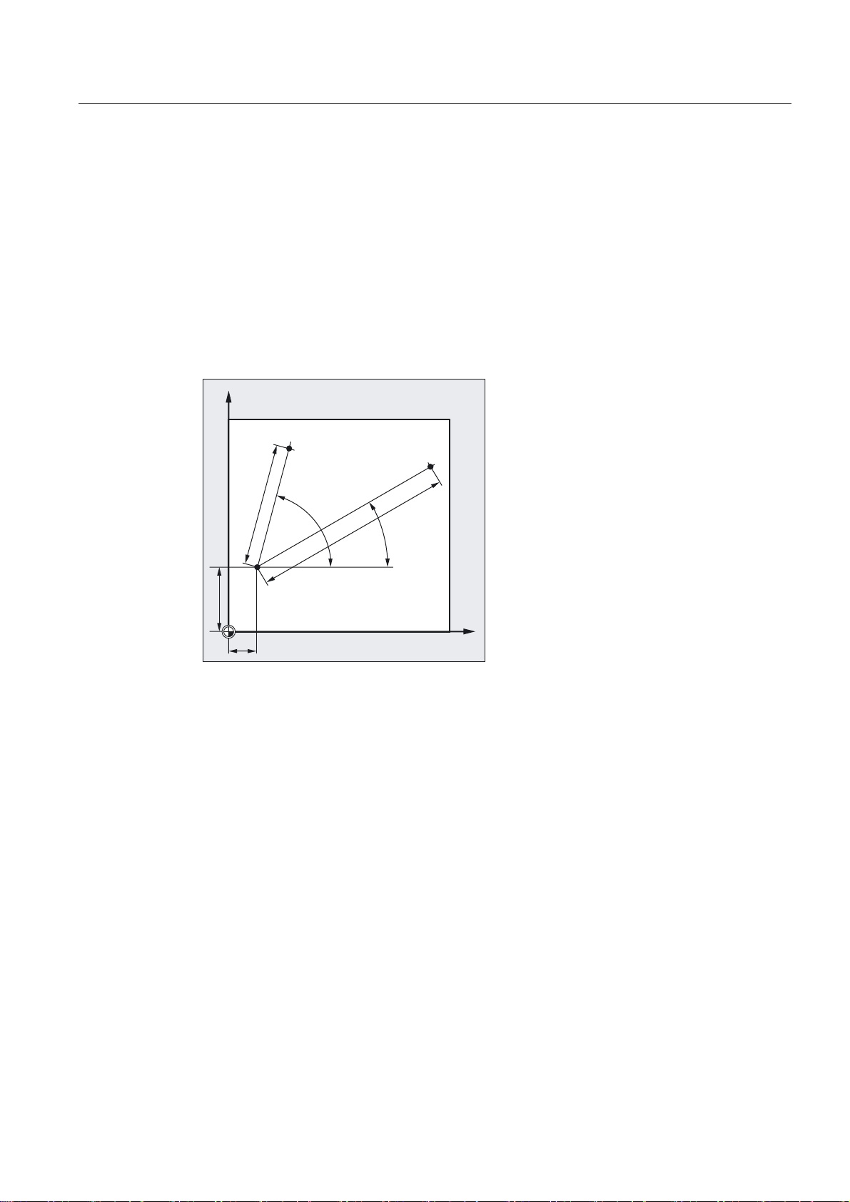
The method used to date to specify points in the coordinate system is known as the
"Cartesian coordinate" method.
However, there is another way to specify coordinates, i.e., as so-called "polar coordinates".
The polar coordinate method is useful only if a workpiece or part of a workpiece has radius
and angle measurements. The point, on which the measurements are based, is called the
"pole".
Example of polar data
The points P1 and P2 can then be described, with reference to the pole, as follows:
<
3
3
¡
¡
3ROH
P1 corresponds to radius =100 plus angle =30°
P2 corresponds to radius =60 plus angle =75°
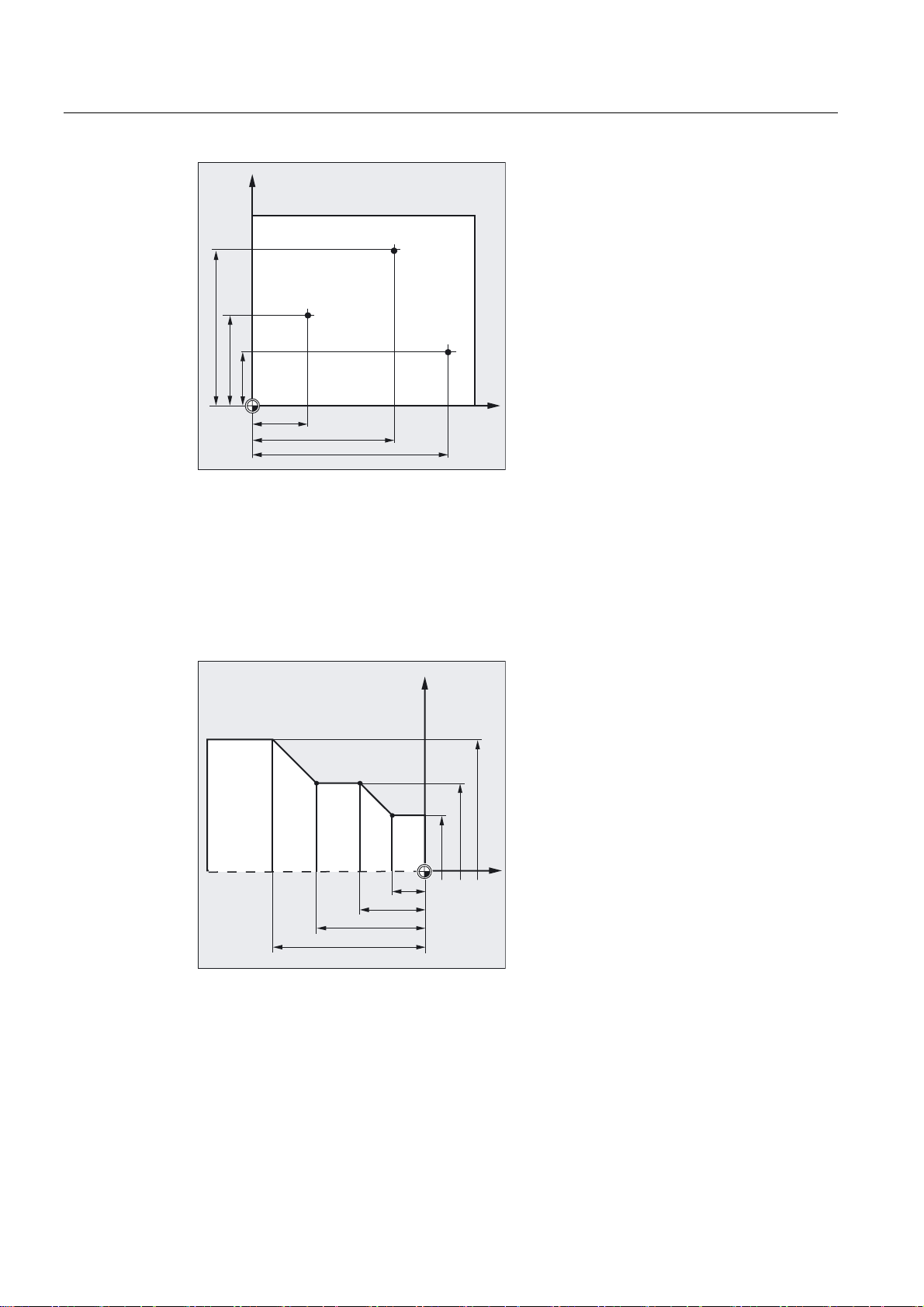
1.1.4 Absolute dimensions
With absolute dimensions, all the positional data refer to the currently valid zero point.
Applied to tool movement this means:
the position, to which the tool is to travel.
Example of milling
The positional parameters for points P1 to P3 in absolute dimensions referring to the zero
point are the following:
;
Fundamentals
Programming Manual, 10.2004 Edition, 6FC5 298-7AB00-0BP1
1-5
Page 20
Fundamental Geometrical Principles
1.1 Description of workpiece points
<
3
3
3
;
P1 corresponds to X20 Y35
P2 corresponds to X50 Y60
P3 corresponds to X70 Y20
Example of turning
The positions for points P1 to P4 in absolute dimensions are as follows with reference to the
zero point:
P1 corresponds to X25 Z-7.5
P2 corresponds to X40 Z-15
P3 corresponds to X40 Z-25
3
3 3
3
;
=
P4 corresponds to X60 Z-35
Fundamentals
1-6 Programming Manual, 10.2004 Edition, 6FC5 298-7AB00-0BP1
Page 21
Fundamental Geometrical Principles
1.1 Description of workpiece points
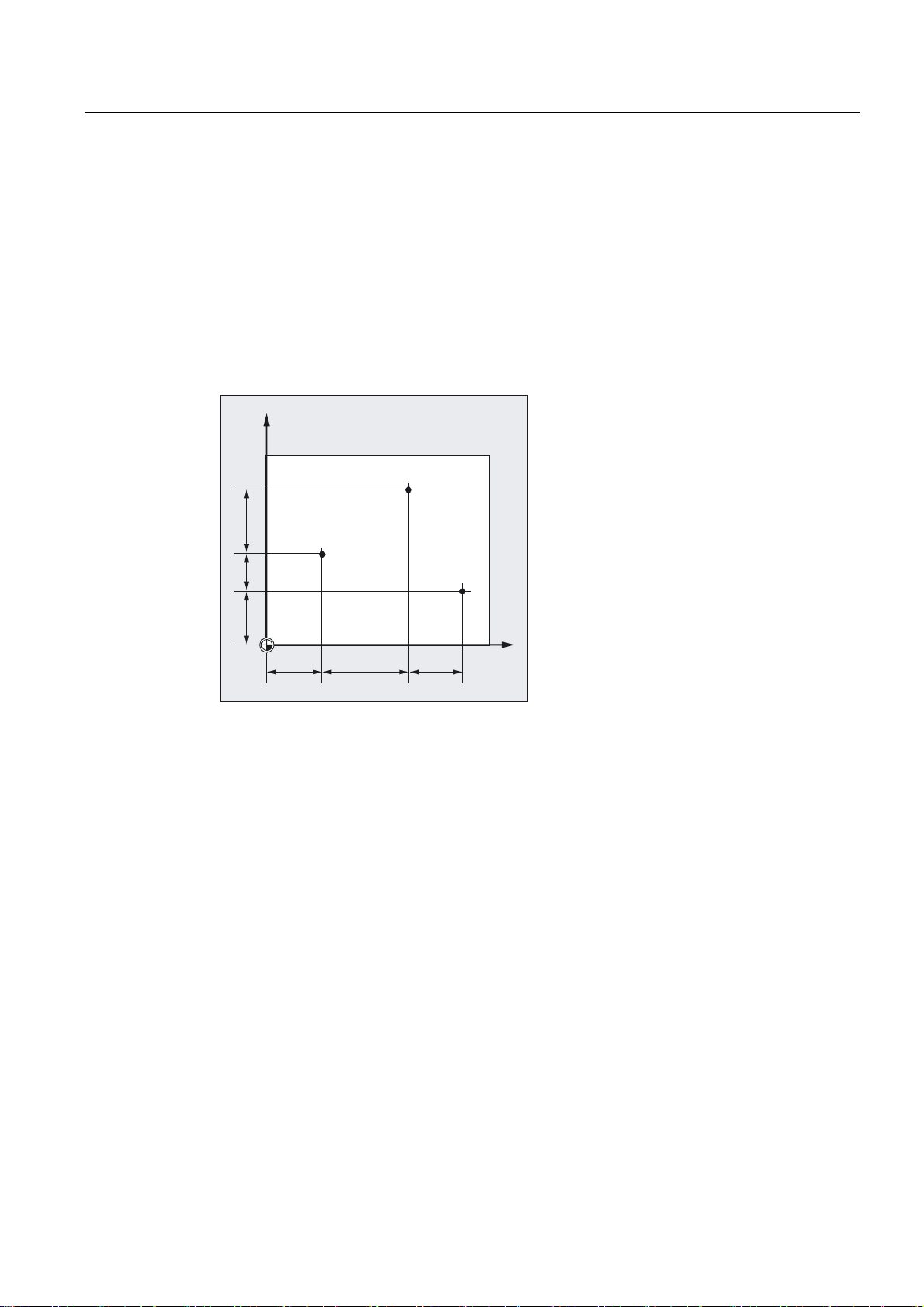
1.1.5 Incremental dimension
Production drawings are frequently encountered, however, where the dimensions refer not to
the origin, but to another point on the workpiece. In order to avoid having to convert such
dimensions, it is possible to specify them in incremental dimensions. Incremental dimensions
refer to the positional data for the previous point. Applied to tool movement this means:
The incremental dimensions describe the distance the tool is to travel.
Example of milling
The positional data for points P1 to P3 in incremental dimensions are:
<
3
3
P1 corresponds to X20 Y35 ;(with reference to the zero point)
P2 corresponds to X30 Y20 ;(with reference to P1)
P3 corresponds to X20 Y-35 ;(with reference to P2)
Example of turning
The positions for points P1 to P4 in incremental dimensions are as follows:
3
;
Fundamentals
Programming Manual, 10.2004 Edition, 6FC5 298-7AB00-0BP1
1-7
Page 22
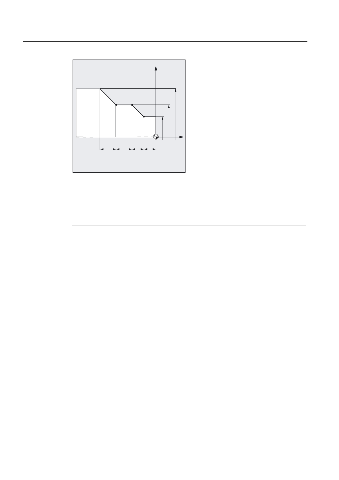
Fundamental Geometrical Principles
1.1 Description of workpiece points
;
3
3 3
3
=
G90 P1 corresponds to X25 Z-7.5 ;(with reference to the zero point)
G91 P2 corresponds to X15 Z-7.5 ;(with reference to P1)
G91 P3 corresponds to Z-10 ;(with reference to P2)
G91 P4 corresponds to X20 Z-10 ;(with reference to P3)
Note
When DIAMOF or DIAM90 is active, the path setpoint is programmed as a radius dimension
with G91.
1.1.6 Plane designations
When programming, it is necessary to specify the working plane so that the control system
can calculate the tool offset values correctly. The plane is also relevant to certain types of
circular programming and polar coordinates.
A plane is defined by means of two coordinate axes.
Fundamentals
1-8 Programming Manual, 10.2004 Edition, 6FC5 298-7AB00-0BP1
Page 23
Fundamental Geometrical Principles
1.1 Description of workpiece points
Milling:
=
<
*
*
*
;
Turning:
Working planes
<
;
*
*
*
=
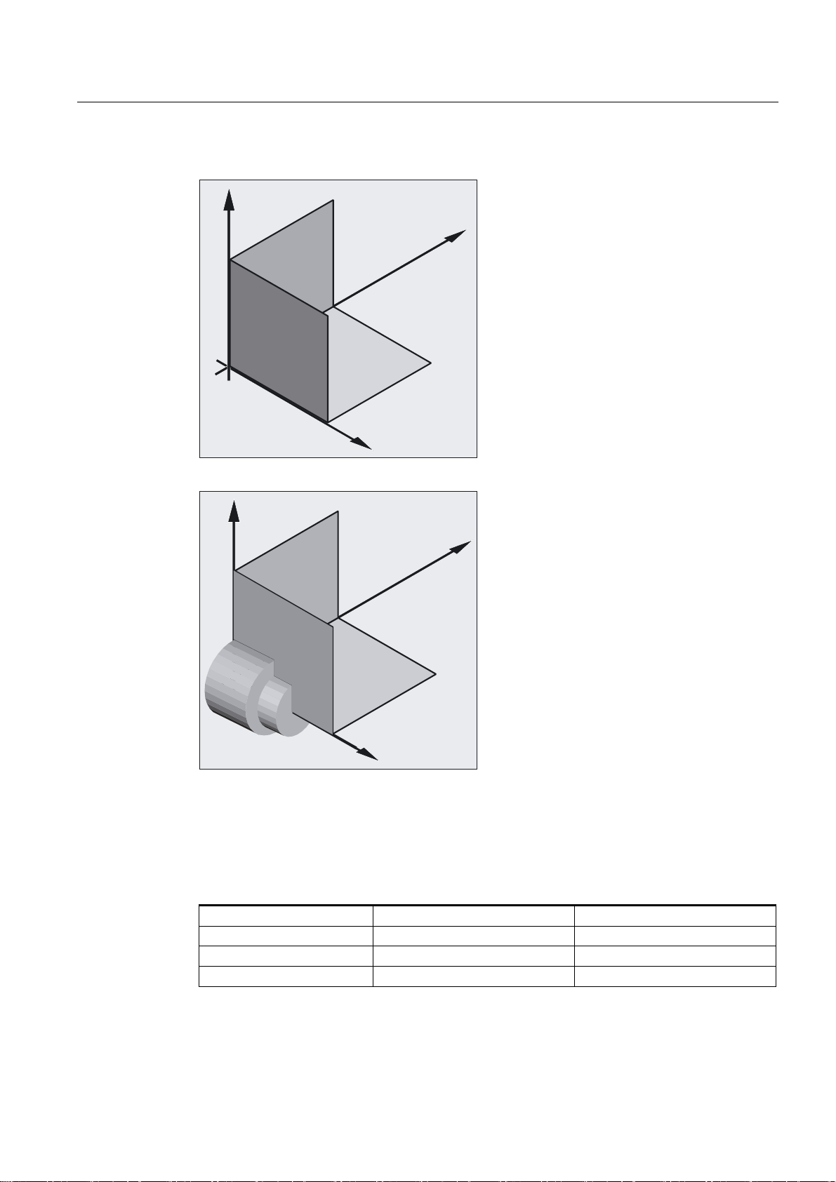
The third coordinate axis is perpendicular to this plane and determines the infeed direction of
the tool (e.g., for 2½ D machining).
The working planes are specified as follows in the NC program with G17, G18 and G19:
Plane
X/Y G17 Z
Z/X G18 Y
Y/Z G19 X
Designation
Infeed direction
Fundamentals
Programming Manual, 10.2004 Edition, 6FC5 298-7AB00-0BP1
1-9
Page 24
Fundamental Geometrical Principles
1.2 Position of zero points
1.2 Position of zero points
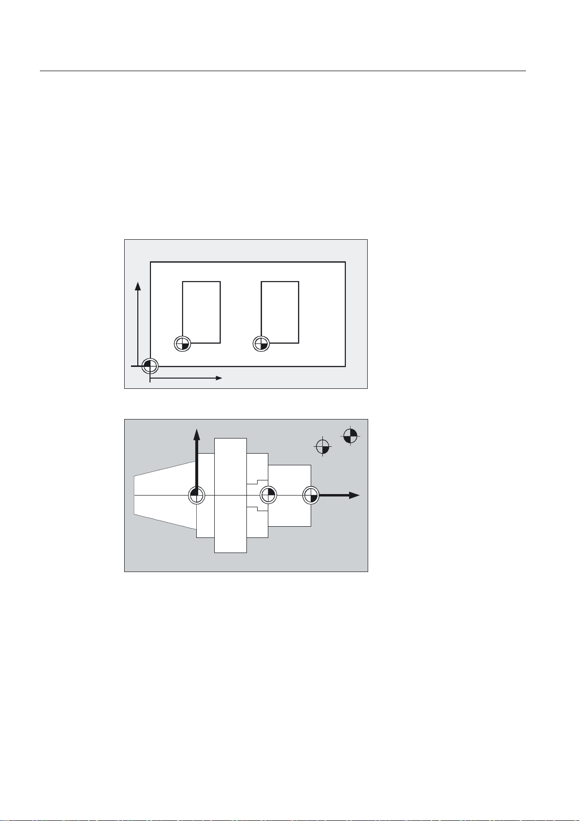
The various origins (zero points) and reference positions are defined on the NC machine.
They are reference points
• for the machine to approach and
• for programming the workpiece dimensions.
The diagrams show the zero points and reference points for drilling/milling machines and
turning machines.
Milling:
<
Reference points
::
0
;
Turning:
;
5
%
0
$
:
=
They are:
M Machine zero
A Blocking point. Can coincide with the workpiece zero point (only turning
machines).
W Workpiece zero = Program zero
Fundamentals
1-10 Programming Manual, 10.2004 Edition, 6FC5 298-7AB00-0BP1
Page 25

Fundamental Geometrical Principles
1.3 Position of coordinate systems
B
R Reference point. Position determined by cams and measuring system.
Start point. Can be defined for each program.
Start point of the first tool for machining.
The distance to the machine zero M must be known, so that the axis
position can be set at this place exactly on this value
1.3 Position of coordinate systems
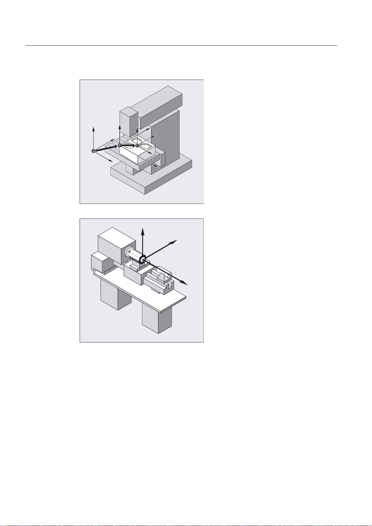
1.3.1 Overview of various coordinate systems
We distinguish between the following coordinate systems:
• The machine coordinate system with the machine zero M
• The basic coordinate system (this can also be the workpiece coordinate system W)
• The workpiece coordinate system with the workpiece zero W
• The current workpiece coordinate system with the current offset workpiece zero Wa
In cases where different machine coordinate systems are in use (e.g., 5-axis transformation),
an internal transformation function mirrors the machine kinematics on the coordinate system
currently selected for programming.
Note
The individual axis identifiers are explained in the subsection headed "Axis types".
Fundamentals
Programming Manual, 10.2004 Edition, 6FC5 298-7AB00-0BP1
1-11
Page 26
Fundamental Geometrical Principles
1.3 Position of coordinate systems
Milling coordinate system:
=
Z
P
=
<
P
0
;
P
=
D
<
Z
<
D
:
:D
;
D
;
Z
Turning coordinate system:
<
0
:
1.3.2 Machine coordinate system
The machine coordinate system comprises all the physically existing machine axes.
Reference points and tool and pallet changing points (fixed machine points) are defined in
the machine coordinate system.
;
=
Fundamentals
1-12 Programming Manual, 10.2004 Edition, 6FC5 298-7AB00-0BP1
Page 27
Fundamental Geometrical Principles
1.3 Position of coordinate systems
Right-hand rule
=P
0
<P
;P
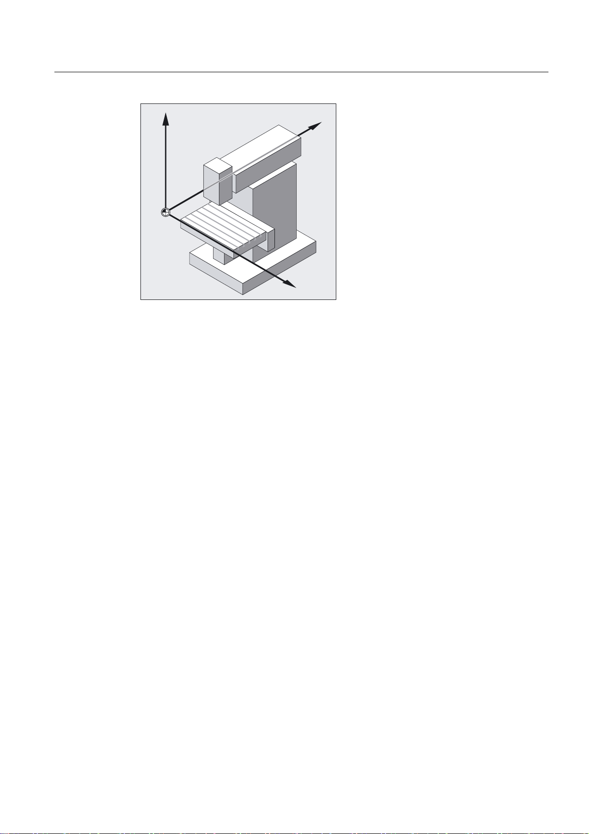
Where the machine coordinate system is used for programming (this is possible with some
of the G functions), the physical axes of the machine are addressed directly. No allowance
is made for workpiece clamping.
The orientation of the coordinate system relative to the machine depends on the machine
type. The axis directions follow the so-called "three-finger rule" of the right hand (in
accordance with DIN 66217).
Seen from in front of the machine, the middle finger of the right hand points in the opposite
direction to the infeed of the main spindle. Therefore:
• the thumb points in the +X direction
• the index finger points in the +Y direction
• the middle finger points in the +Z direction
Fundamentals
Programming Manual, 10.2004 Edition, 6FC5 298-7AB00-0BP1
1-13
Page 28

Fundamental Geometrical Principles
1.3 Position of coordinate systems
=
<
;
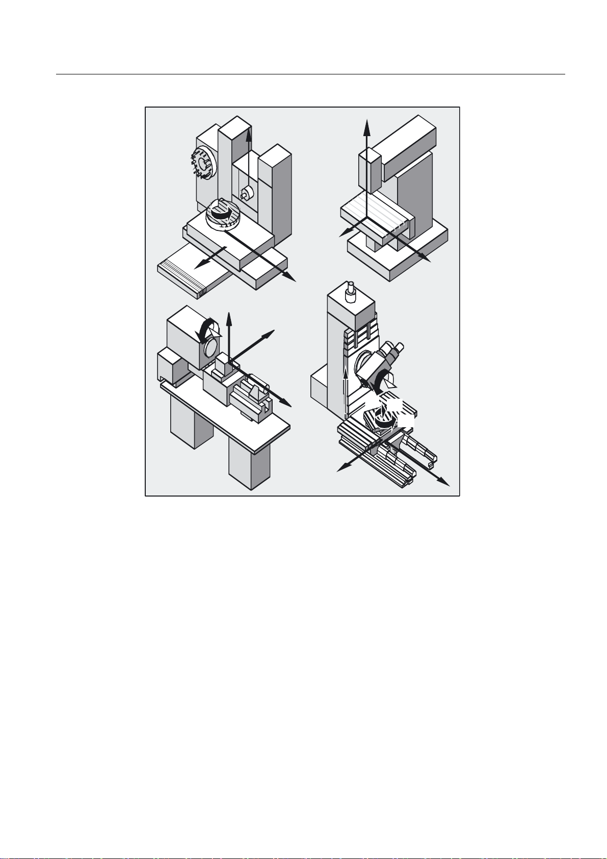
Determination from the right hand rule for different machine types
With different machine types the determination from the right hand rule can look different in
each case. The following are examples of machine coordinate systems for various
machines.
Fundamentals
1-14 Programming Manual, 10.2004 Edition, 6FC5 298-7AB00-0BP1
Page 29
Fundamental Geometrical Principles
1.3 Position of coordinate systems
=
=
%
<
<
&
<
&
1.3.3 Basic coordinate system
;
=
;
=
;
%
;
%
$
$
<
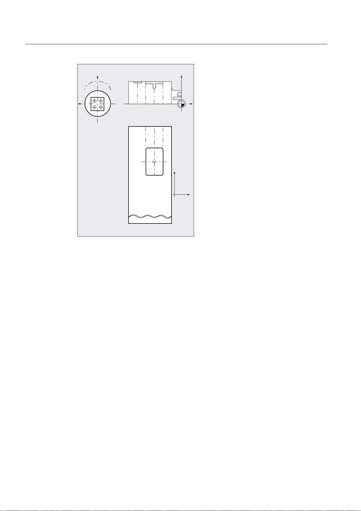
The basic coordinate system is a Cartesian coordinate system, which is mirrored by
kinematic transformation (for example, 5-axis transformation or by using Transmit with
peripheral surfaces) onto the machine coordinate system.
Fundamentals
Programming Manual, 10.2004 Edition, 6FC5 298-7AB00-0BP1
1-15
Page 30
Fundamental Geometrical Principles
1.3 Position of coordinate systems
%DVLFFRRUGLQDWHV\VWHP
IRUIURQWIDFH
;
<
%DVLF
FRRUGLQDWHV\VWHP
IRUSHULSKHUDOVXUIDFH
:RUNSLHFH
FRRUGLQDWHV\VWHP
IRUSODQHRIURWDWLRQ
:
;
=
<
=
If there is no kinematic transformation, the basic coordinate system differs from the machine
coordinate system only in terms of the axis designations.
The activation of a transformation can produce deviations in the parallel orientation of the
axes. The coordinate system does not have to be at a right angle.
Fundamentals
1-16 Programming Manual, 10.2004 Edition, 6FC5 298-7AB00-0BP1
Page 31
Fundamental Geometrical Principles
1.3 Position of coordinate systems
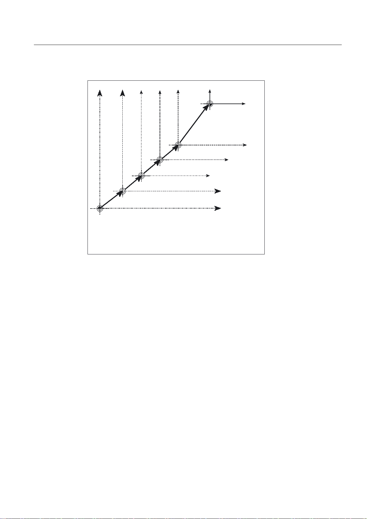
Further determinations
<0&6
<%&6
<%=6
<6=6
<:&6
:&6
;:&6
%=6
%DVLFIUDPHEDVLFRIIVHW
'5)RIIVHW]HURRIIVHWH[WHUQDO
%&6
.LQHPDWLFWUDQVIRUPDWLRQ
0&6
0&6 0DFKLQH&RRUGLQDWH6\VWHP%&6 %DVLF&RRUGLQDWH6\VWHP
%=6 %DVLF=HUR6\VWHP 6=6 6HWWDEOH=HUR6\VWHP
:&6 :RUNSLHFH&RRUGLQDWH6\VWHP
Zero offsets, scaling, etc., are always executed in the basic coordinate system.
The coordinates also refer to the basic coordinate system when specifying the working field
limitation.
1.3.4 Workpiece coordinate system
3URJUDPPDEOH)5$0(
6=6
**VHWWDEOH)5$0(6
;%&6
;0&6
;%=6
;6=6
The geometry of a workpiece is described in the workpiece coordinate system. In other
words, the data in the NC program refer to the workpiece coordinate system.
Fundamentals
Programming Manual, 10.2004 Edition, 6FC5 298-7AB00-0BP1
1-17
Page 32
Fundamental Geometrical Principles
1.3 Position of coordinate systems
=
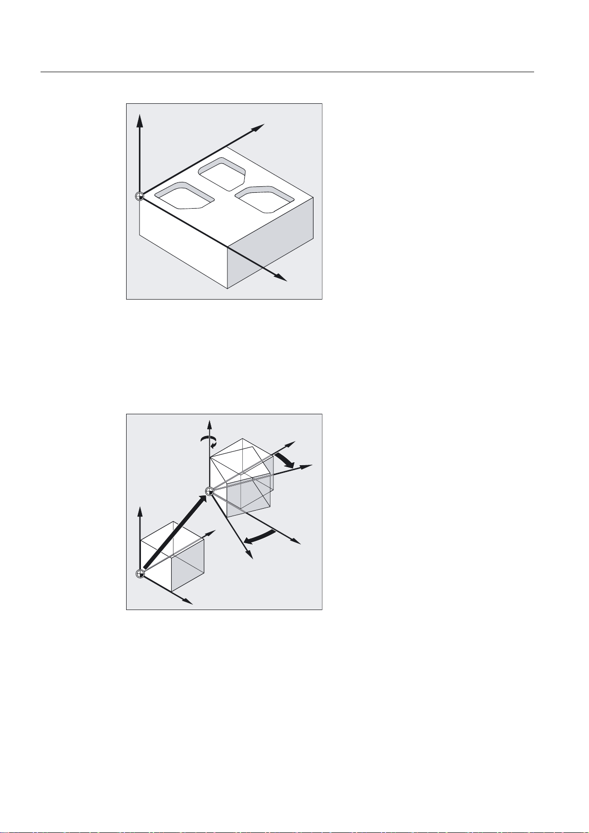
The workpiece coordinate system is always a Cartesian coordinate system and assigned to
a specific workpiece.
1.3.5 Frame system
The frame is a self-contained arithmetic rule that transforms one Cartesian coordinate
system into another Cartesian coordinate system.
<
;
= =
5RWDWLRQ
DURXQGWKH=D[LV
=
<
=HURRIIVHW
;
;
<
<
;
It is a spatial description of the workpiece coordinate system
The following components are available within a frame:
• Zero offset
• Rotate
• Mirroring
• Scaling
Fundamentals
1-18 Programming Manual, 10.2004 Edition, 6FC5 298-7AB00-0BP1
Page 33
Fundamental Geometrical Principles
1.3 Position of coordinate systems
These components can be used individually or in any combination.
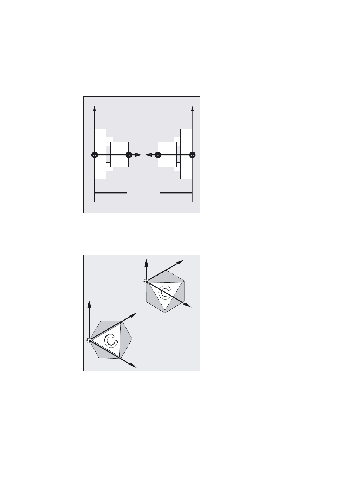
Mirroring of the Z axis
;
=
=
0
=HURRIIVHW
:
:
=HURRIIVHW
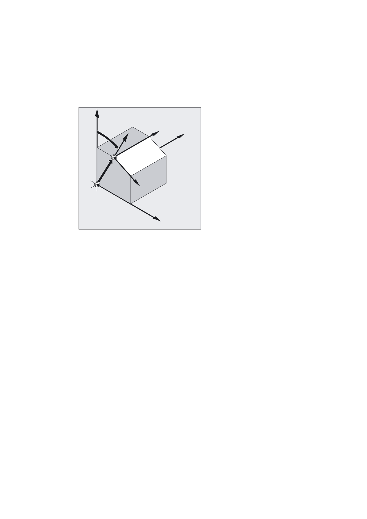
Shifting and turning the workpiece coordinate system
One way of machining inclined contours is to use appropriate fixtures to align the workpiece
parallel to the machine axes.
=
;
0
<
=
<
;
... Another way is to generate a coordinate system, which is oriented to the workpiece. The
coordinate system can be moved and/or rotated with programmable frames.
This enables you to
• move the zero point to any position on the workpiece
Fundamentals
Programming Manual, 10.2004 Edition, 6FC5 298-7AB00-0BP1
;
1-19
Page 34
Fundamental Geometrical Principles
1.3 Position of coordinate systems
• align the coordinate axes parallel to the desired working plane by rotation
• and thus machine surfaces clamped in inclined positions, produce drill holes at different
angles.
• Performing multi-side machining operations.
=
<
=
;
;
<
The conventions for the working plane and the tool offsets must be observed – in
accordance with the machine kinematics – for machining operations in inclined working
planes.
For further information, please see "Selection of working plane, G17 to G19".
1.3.6 Assignment of workpiece coordinate system to machine axes
The location of the workpiece coordinate system in relation to the basic coordinate system
(or machine coordinate system) is determined by settable frames.
Fundamentals
1-20 Programming Manual, 10.2004 Edition, 6FC5 298-7AB00-0BP1
Page 35
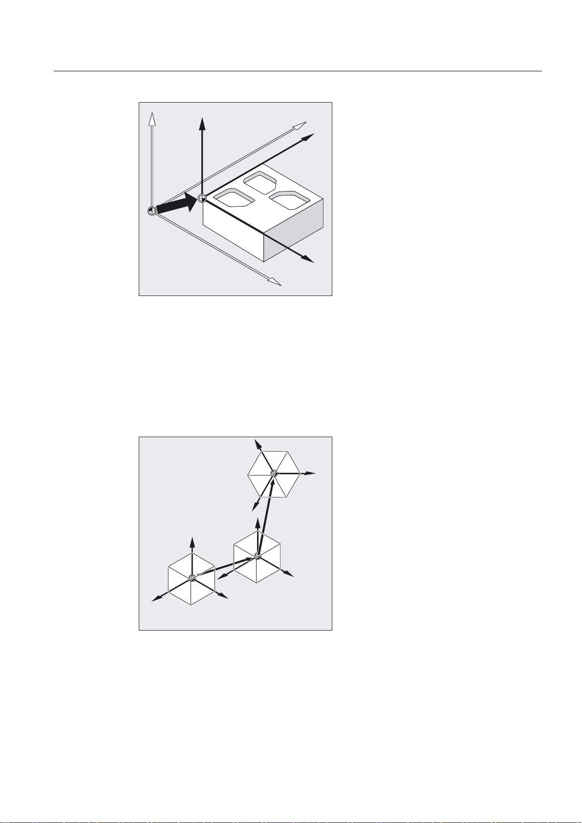
Fundamental Geometrical Principles
1.3 Position of coordinate systems
<0 =
;0 ;
%
<
0
;
:
%
0
=0 =
*
%
=
:
The settable frames are activated in the NC program by means of commands such as G54.
1.3.7 Current workpiece coordinate system
Sometimes it is advisable or necessary to reposition and to rotate, mirror and/or scale the
originally selected workpiece coordinate system within a program.
The programmable frames can be used to reposition (rotate, mirror and/or scale) the current
zero point at a suitable point in the workpiece coordinate system. You will thus obtain the
current workpiece coordinate system.
<
&XUUHQWZRUNSLHFH
FRRUGLQDWHV\VWHP
=
<
<%
)UDPH
=
=%
)UDPHVHWWDEOHRIIVHWDQGURWDWLRQ
)UDPHSURJUDPPDEOHRIIVHWDQGURWDWLRQ
;%
Several zero offsets are possible in the same program.
)UDPH
;
:RUNSLHFH
FRRUGLQDWHV\VWHP
;
Fundamentals
Programming Manual, 10.2004 Edition, 6FC5 298-7AB00-0BP1
1-21
Page 36
Fundamental Geometrical Principles
1.4 Axes
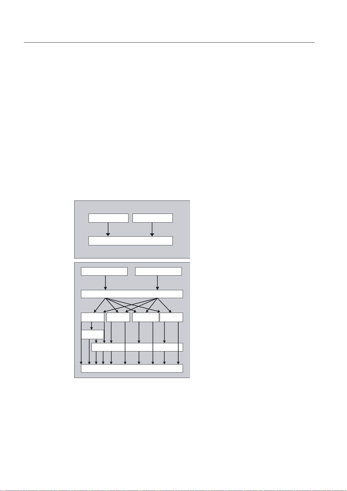
1.4 Axes
A distinction is made between the following types of axes when programming:
• Machine axes
• Channel axes
• Geometry axes
• Special axes
• Path axes
• Synchronized axes
• Positioning axes
• Command axes (motion-synchronous actions)
• PLC axes
• Link axes
• Lead link axes
*HRPHWU\D[HV
0DFKLQHD[HV
*HRPHWU\D[HV
3DWKD[HV
6\QFKU
D[HV
3RVLWLRQLQJ
D[HV
.LQHPDWLFWUDQVIRUPDWLRQ
3RVLWLRQLQJD[HV
&KDQQHOD[HV
&RPPDQG
D[HV
0DFKLQHD[HV
6SHFLDOD[HV
3/&D[HV
Behavior of programmed axis types
Geometry, synchronized and positioning axes are programmed.
• Path axes traverse with feedrate F in accordance with the programmed travel commands.
Fundamentals
1-22 Programming Manual, 10.2004 Edition, 6FC5 298-7AB00-0BP1
Page 37
Fundamental Geometrical Principles
1.4 Axes
• Synchronized axes traverse synchronously to path axes and take the same time to
traverse as all path axes.
• Positioning axes traverse asynchronously to all other axes. These traversing movements
take place independently of path and synchronized movements.
• Command axes traverse asynchronously to all other axes. These traversing movements
take place independently of path and synchronized movements.
• PLC axes are controlled by the PLC and can traverse asynchronously to all other axes.
The traversing movements take place independently of path and synchronized
movements.
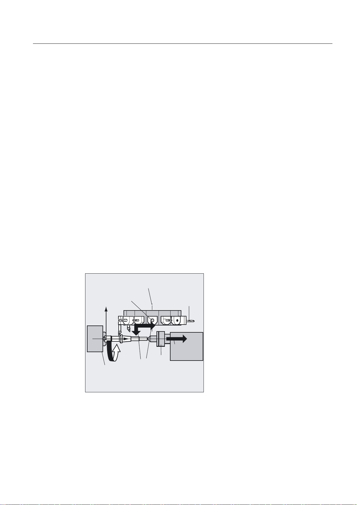
1.4.1 Main axes/Geometry axes
The main axes define a right-angled, right-handed coordinate system. Tool movements are
programmed in this coordinate system.
In NC technology, the main axes are called geometry axes. This term is also used in this
Programming Guide.
The "Switchable geometry axes" function (see Advanced) can be used to alter the geometry
axes grouping configured by machine data. Here any geometry axis can be replaced by a
channel axis defined as a synchronous special axis.
Axis identifier
For turning machines:
Geometry axes X and Z are used, and sometimes Y.
5HYROYHUVZLYHO
D[LV
7RROV
;
0DLQVSLQGOH
PDVWHUVSLQGOH
&D[LV
=
*HRPHWU\
D[HV
6SHFLDOVSLQGOH
6SHFLDOD[LV
7DLO
VWRFN
For milling machines:
Geometry axes X, Y and Z are used.
A maximum of three geometry axes are used for programming frames and the workpiece
geometry (contour).
Fundamentals
Programming Manual, 10.2004 Edition, 6FC5 298-7AB00-0BP1
1-23
Page 38

Fundamental Geometrical Principles
1.4 Axes
The identifiers for geometry and channel axes may be the same, provided a reference is
possible.
Geometry axis and channel axis names can be the same in any channel so that the same
programs can be executed.
1.4.2 Special axes
In contrast to the geometry axes, no geometrical relationship is defined between the special
axes.
Axis identifier
In a turning machine with revolver magazine, for example,
Turret position U, tailstock V
Application examples
Typical special axes are tool revolver axes, swivel table axes, swivel head axes, and loader
axes.
N10 G1 X100 Y20 Z30 A40 F300 ;Path axis movements
N20 POS[U]=10POS[X]=20 FA[U]=200 FA[X]=350 ;Positioning axis movements
N30 G1 X500 Y80 POS[U]=150FA[U]=300 F550 ;Path and positioning axis
N40 G74 X1=0 Z1=0 ;Approaching a reference point
1.4.3 Main spindle, master spindle
The machine kinematics determine, which spindle is the main spindle. This spindle is
declared the master spindle in the machine data. As a rule, the main spindle is declared the
master spindle. This assignment can be changed with the program command SETMS
(spindle number). By issuing SETMS without statement of the spindle number you can
switch back to the master spindle defined in the machine data. Special functions such as
thread cutting apply to the master spindle, see "Spindle speed S, spindle direction of rotation
M3, M4, M5".
Spindle identifier
Identifiers: S or S0
1.4.4 Machine axes
Machine axes are the axes physically existing on a machine. The movements of axes can
still be assigned by transformations (TRANSMIT, TRACYL, or TRAORI) to the machine
axes. If transformations are intended for the machine, different axis names must be
determined.
Fundamentals
1-24 Programming Manual, 10.2004 Edition, 6FC5 298-7AB00-0BP1
Page 39

Fundamental Geometrical Principles
1.4 Axes
The machine axis names are programmed only in special cases, such as reference point or
fixed point approaching.
Axis identifier
The axis identifiers can be set in the machine data.
Standard identifiers:
X1, Y1, Z1, A1, B1, C1, U1, V1
There are also standard axis identifiers that can always be used:
AX1, AX2, ..., AXn
1.4.5 Channel axes
Channel axes are all axes, which traverse in a channel.
Axis identifier
Identifiers: X, Y, Z, A, B, C, U, V
1.4.6 Path axes
Path axes define the path and therefore the movement of the tool in space.
The programmed feed is active for this path. The axes involved in this path reach their
position at the same time. As a rule, these are the geometry axes.
However, default settings define, which axes are the path axes, and therefore determine the
velocity.
Path axes can be specified in the NC program with FGROUP, see "Path behavior".
1.4.7 Positioning axes
Positioning axes are interpolated separately, i.e., each positioning axis has its own axis
interpolator and its own feedrate. Positioning axes do not interpolate with the path axes.
Positioning axes are traversed by the NC program or the PLC. If an axis is to be traversed
simultaneously by the NC program and the PLC, an error message appears.
Typical positioning axes are:
• Loaders for moving workpieces to machine
Fundamentals
Programming Manual, 10.2004 Edition, 6FC5 298-7AB00-0BP1
1-25
Page 40

Fundamental Geometrical Principles
1.4 Axes
• Loaders for moving workpieces away from machine
• Tool magazine/turret
Programming
A distinction is made between positioning axes with synchronization at the block end or over
several blocks.
Parameters
POS axes:
Block change occurs at the end of the block when all the path and positioning axes
programmed in this block have reached their programmed end point.
POSA axes:
The movement of these positioning axes can extend over several blocks.
POSP axes:
The movement of these positioning axes for approaching the end position takes place in
sections.
Note
Positioning axes become synchronized axes if they are traversed without the special
POS/POSA identifier.
Continuous-path mode (G64) for path axes is only possible if the positioning axes (POS)
reach their final position before the path axes.
Path axes that are programmed with POS/POSA are removed from the path axis grouping
for the duration of this block.
You will find further information on POS, POSA, and POSP in the section on "Traversing
positioning axes, POS, POSA, POSP".
1.4.8 Synchronized axes
Synchronized axes traverse synchronously to the path from the start position to the
programmed end position.
The feedrate programmed in F applies to all the path axes programmed in the block, but
does not apply to synchronized axes. Synchronized axes take the same time as the path
axes to traverse.
A synchronized axis can be a rotary axis, which is traversed synchronously to the path
interpolation.
Fundamentals
1-26 Programming Manual, 10.2004 Edition, 6FC5 298-7AB00-0BP1
Page 41
Fundamental Geometrical Principles
1.4 Axes
1.4.9 Command axes
Command axes are started from synchronized actions in response to an event (command).
They can be positioned, started, and stopped fully asynchronous to the parts program. An
axis cannot be moved from the parts program and from synchronized actions
simultaneously.
Command axes are interpolated separately, i.e., each command axis has its own axis
interpolator and its own feedrate.
References:/FBSY/, Synchronized Actions
1.4.10 PLC axes
PLC axes are traversed by the PLC via special function blocks in the basic program; their
movements can be asynchronous to all other axes. The traversing movements take place
independently of path and synchronized movements..
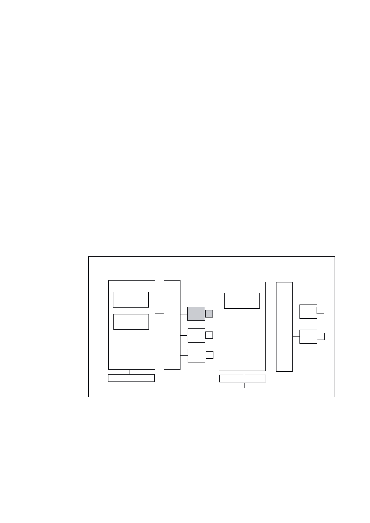
1.4.11 Link axes
Link axes are axes, which are physically connected to another NCU and whose position is
controlled from this NCU. Link axes can be assigned dynamically to channels of another
NCU. Link axes are not local axes from the perspective of a particular NCU.
The axis container concept is used for the dynamic modification of the assignment to an
NCU. Axis substitution with GET and RELEASE from the parts program is not available for
link axes.
1&8
&KDQQHO
&KDQQHO
/LQNPRGXOH+:
'
$
$
$
/LQNFRPPXQLFDWLRQ
1&8
&KDQQHO
/LQNPRGXOH+:
'
%
%
Fundamentals
Programming Manual, 10.2004 Edition, 6FC5 298-7AB00-0BP1
1-27
Page 42

Fundamental Geometrical Principles
1.4 Axes
Precondition
The participating NCUs, NCU1 and NCU2, must be connected by means of high-speed
communication via the link module.
References:
/PHD/, Configuring Manual NCU 571-573.2, Link Module
The axis must be configured appropriately by machine data.
The link axis option must be installed.
Description
The position control is implemented on the NCU on which the axis is physically connected to
the drive. This NCU also contains the associated axis VDI interface. The position setpoints
for link axes are generated on another NCU and communicated via the NCU link.
The link communication must provide the means of interaction between the interpolators and
the position controller or PLC interface. The setpoints calculated by the interpolators must be
transported to the position control loop on the home NCU and, vice versa, the actual values
must be returned from there back to the interpolators.
For further information about link axes, please refer to
References: Function description /FB/ B3, Multiple Operator Panels and NCUs
Axis container
An axis container is a circular buffer data structure in which local axes and/or link axes are
assigned to channels. The entries in the circular buffer can be shifted cyclically.
In addition to the direct reference to local axes or link axes, the link axis configuration in the
logical machine axis image also allows references to axis containers. This type of reference
consists of:
• a container number and
• a slot (circular buffer location within the container)
The entry in a circular buffer location contains:
• a local axis or
• a link axis
Axis container entries contain local machine axes or link axes from the perspective of an
individual NCU. The entries in the logical machine axis image
MN_AXCONF_LOGIC_MACHAX_TAB of an individual NCU are fixed.
The axis container function is described in
References: Function description /FB/ B3, Multiple Operator Panels and NCUs
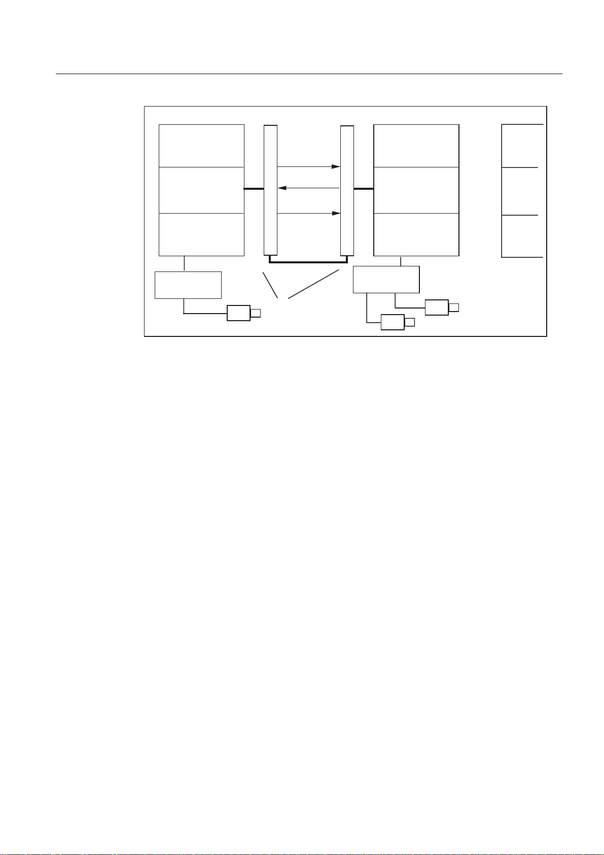
1.4.12 Lead link axes
A leading link axis is one that is interpolated by one NCU and utilized by one or several other
NCUs as the master axis for controlling slave axes.
Fundamentals
1-28 Programming Manual, 10.2004 Edition, 6FC5 298-7AB00-0BP1
Page 43
Fundamental Geometrical Principles
1.4 Axes
'
%
1&8
,QWHUSRODWRU
6HUYR
%
1&8Q
1&8
,QWHUSRODWRU
6HUYR
'
$
6HWSRLQWVIURP$
&KDQQHOFRQWURO
E\IROORZLQJ
D[LVD[HV
$FWXDOYDOXHV
IURP$
1&8OLQNPRGXOH
An axial position controller alarm is sent to all other NCUs, which are connected to the
affected axis via a leading link axis.
NCUs that are dependent on the leading link axis can utilize the following coupling
relationships with it:
• Master value (setpoint, actual master value, simulated master value)
• Coupled motion
Programming
Prerequisites
• Tangential correction
• Electronic gear (ELG)
• Synchronous spindle
Master NCU:
Only the NCU, which is physically assigned to the master value axis can program travel
motions for this axis. The travel program must not contain any special functions or
operations.
NCUs of slave axes:
The travel program on the NCUs of the slave axes must not contain any travel commands for
the leading link axis (master value axis). Any violation of this rule triggers an alarm.
The leading link axis is addressed in the usual way via channel axis identifiers. The states of
the leading link axis can be accessed by means of selected system variables.
• The dependent NCUs, i.e., NCU1 to NCUn (n equals, max. of 8), must be interconnected
via the link module for high-speed communication.
References:
/PHD/, Configuring Manual NCU 571-573.2, Link Module
Fundamentals
Programming Manual, 10.2004 Edition, 6FC5 298-7AB00-0BP1
1-29
Page 44

Fundamental Geometrical Principles
1.5 Coordinate systems and workpiece machining
• The axis must be configured appropriately by machine data.
• The link axis option must be installed.
• The same interpolation cycle must be configured for all NCUs connected to the leading
link axis.
Restrictions
• A master axis, which is leading link axis cannot be a link axis, i.e., it cannot be operated
by NCUs other than its home NCU.
• A master axis, which is leading link axis cannot be a container axis, i.e., it cannot be
addressed alternately by different NCUs.
• A leading link axis cannot be the programmed leading axis in a gantry grouping.
• Couplings with leading link axes cannot be cascaded.
• Axis replacement can only be implemented within the home NCU of the leading link axis.
System variables:
The following system variables can be used in conjunction with the channel axis identifier of
the leading link axis:
• $AA_LEAD_SP; Simulated master value position
• SAA_LEAD_SV; Simulated master value velocity
If these system variables are updated by the home NCU of the master axis, the new values
are also transferred to any other NCUs, which wish to control slave axes as a function of this
master axis.
References: /FB/ Function description B3, Multiple Operator Panels and NCUs
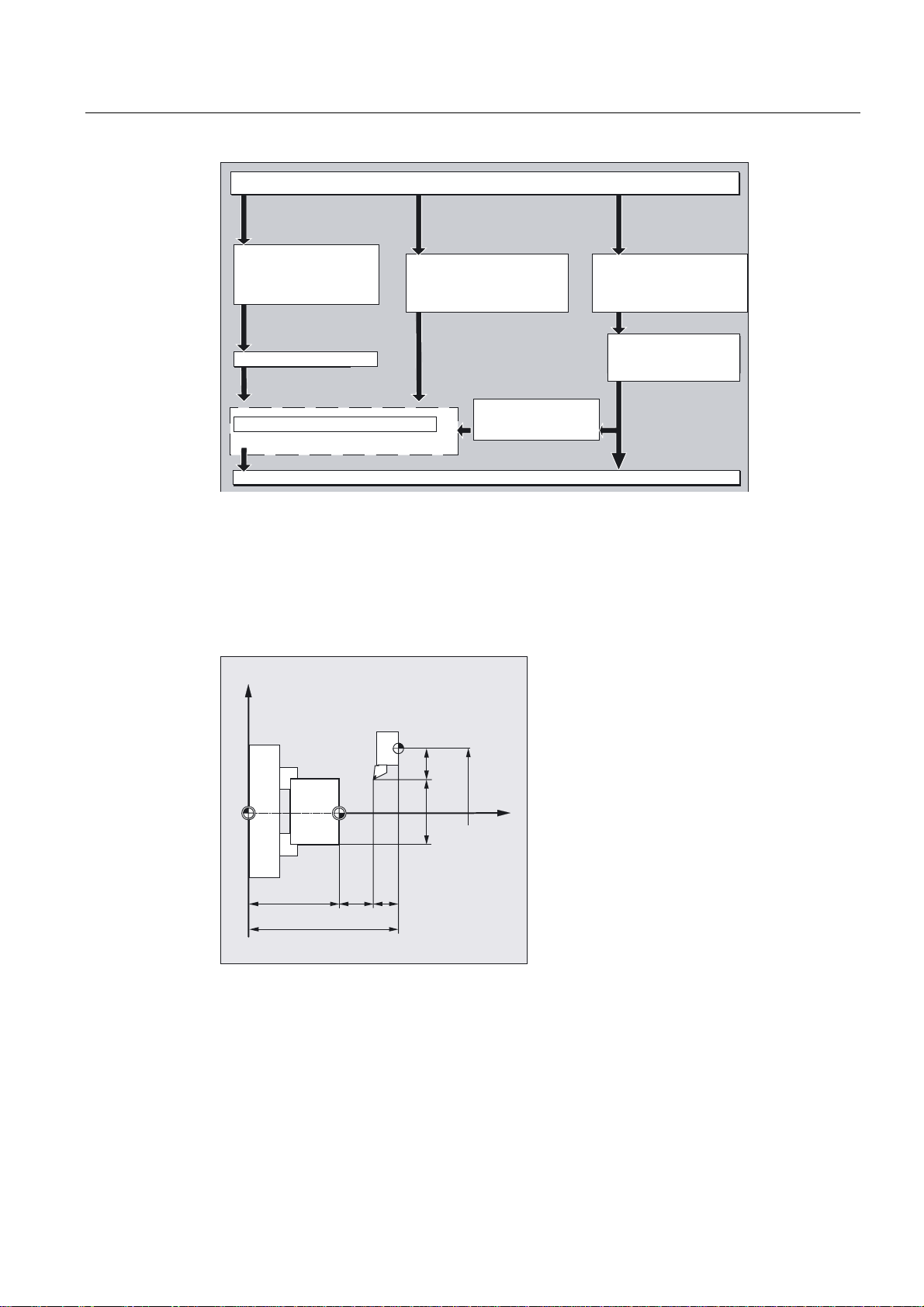
1.5 Coordinate systems and workpiece machining
The relationship between travel commands of the programmed axis movements from the
workpiece coordinates and the resulting machine movement is displayed.
How you can determine the distance traveled taking into account all shifts and corrections is
shown by reference to the path calculation.
Relationship between the travel commands from workpiece coordinates and the resulting machine
movements
Axis movement programmed in the workpiece coordinate system
Fundamentals
1-30 Programming Manual, 10.2004 Edition, 6FC5 298-7AB00-0BP1
Page 45
Fundamental Geometrical Principles
1.5 Coordinate systems and workpiece machining
$[LVPRYHPHQWSURJUDPPHGLQWKHZRUNSLHFHFRRUGLQDWHV\VWHP
'HVFULSWLRQRIWKH
ZRUNSLHFHJHRPHWU\YLDJHRPHWU\
D[HVHJ;<=
)UDPHFDOFXODWLRQ
2IIVHW75$16
5RWDWLRQ527
6FDOLQJ6&$/(
&RQWRXULQ&DUWHVLDQ
FRRUGLQDWHV\VWHP
RIWKHFKDQQHO%&6
7RROUDGLXVFRPSHQVDWLRQ
0RYHPHQWRI
WRRO]HUR
LQ%&6
7RROOHQJWKFRPSHQVDWLRQ
.LQHPDWLFWUDQVIRUPDWLRQLIDFWLYH
'HVFULSWLRQRIWRRO
RULHQWDWLRQE\PHDQVRI
RULHQWDWLRQYHFWRU(XOHUDQJOH
5RWDU\D[HVIRU
D[LVWUDQVIRUPDWLRQ
5HPDLQLQJWUDYHUVLQJ
LQVWUXFWLRQV
YLDVRFDOOHGVSHFLDOD[HV
HJ&89
)UDPHFDOFXODWLRQ
2IIVHW
6FDOLQJ
Path calculation
0RYHPHQWRIPDFKLQHD[HVRIFKDQQHODEF
The path calculation determines the distance to be traversed in a block, taking into account
all offsets and compensations.
In general:
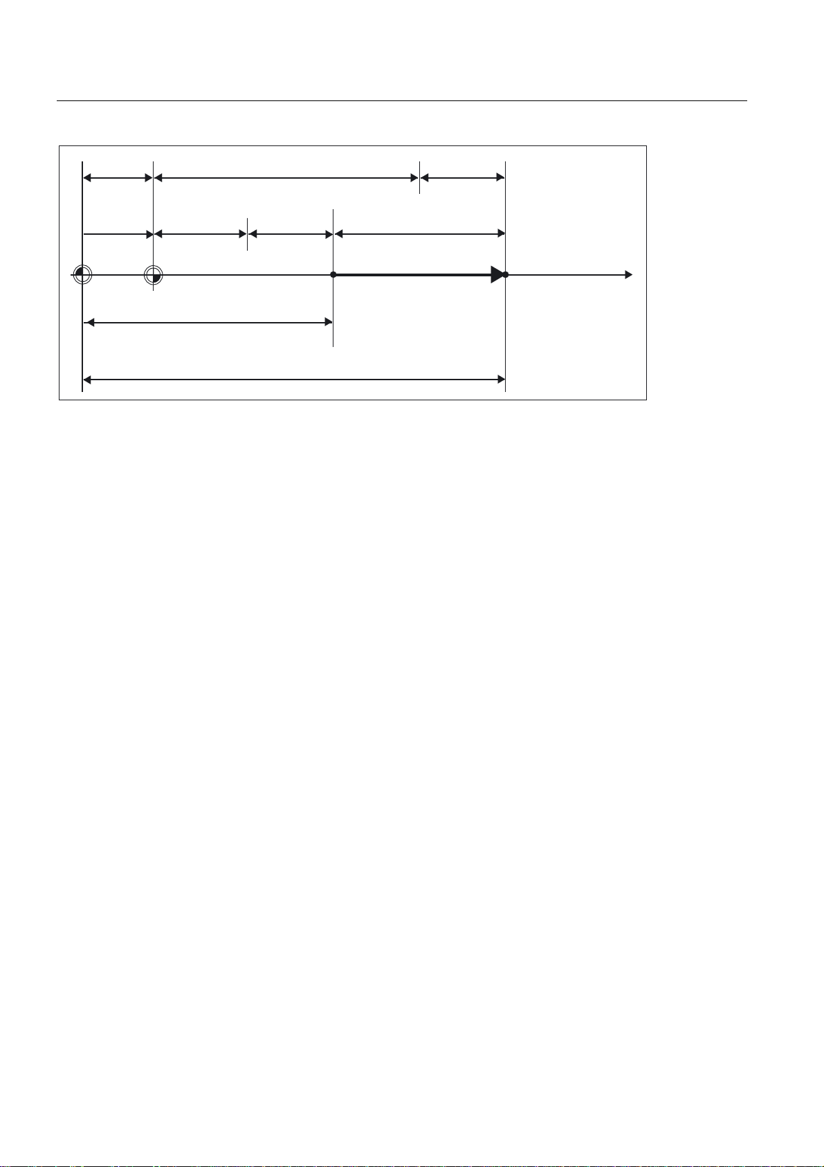
Distance = setpoint - actual value + zero offset (ZO) + tool offset (TO)
;
7
:.
SRLQW
9DOXH
$EVROXWH
0
=2
$EVROXWHSRVLWLRQ
:
6HW
SRLQW
YDOXH
6HW
:.
SRVLWLRQ
=
If a new zero offset and a new tool offset are programmed in a new program block, the
following applies:
• With absolute dimensioning:
Distance = (absolute dimension P2 - absolute dimension P1) + (ZO P2 - ZO P1) + (TO P2
- TO P1).
• With incremental dimensioning:
Distance = incremental dimension + (ZO P2 - ZO P1) + (TO P2 - TO P1).
Fundamentals
Programming Manual, 10.2004 Edition, 6FC5 298-7AB00-0BP1
1-31
Page 46
Fundamental Geometrical Principles
1.5 Coordinate systems and workpiece machining
193
193
0
$EVROXWHGLPHQVLRQVVHWSRLQWIRU3
$EVROXWH
GLPHQVLRQV
VHWSRLQW
IRU3
:
$FWXDOYDOXH
:.3
$FWXDOYDOXH
3
0RWLRQ
:.3
'LVWDQFH
3
Fundamentals
1-32 Programming Manual, 10.2004 Edition, 6FC5 298-7AB00-0BP1
Page 47

Fundamental Principles of NC Programming
2.1 Structure and contents of an NC program
Note
DIN 66025 is the guideline for designing a parts program.
An (NC/part) program consists of a sequence of NC blocks (see table below). Each data
block represents one machining step. Instructions are written in the blocks in the form of
words. The last block in the execution sequence contains a special word for the end of
program: M2, M17 or. M30.
Set Word Word Word ... ;Comment
Set N10 G0 X20 ... ;1st Set
Set N20 G2 Z37 ... ;2nd Set
Set N30 G91 ... ... ;...
Set N40 ... ... ...
Set N50 M30 ... ... ;End of program (last block)
2
Program names
Each program has a different name; the name can be chosen freely during program creation
(except for punch tape format), taking the following conditions into account:
• The first two characters must be letters (or a letter with an underscore character)
• other letters, digits
Example:
_MPF100 or
SHAFT or
SHAFT_2
Only the first 24 characters of a program identifier are displayed on the NC.
Punch tape format
File names:
Fundamentals
Programming Manual, 10.2004 Edition, 6FC5 298-7AB00-0BP1
2-1
Page 48

Fundamental Principles of NC Programming
2.2 Language elements of the programming language
File names can contain the characters 0...9, A...Z, a...z or _ and must not exceed 24
characters in total.
File names must have a 3-character extension (_xxx).
Data in punch tape format can be generated externally or processed with an editor. A file
name of a file that is filed internally in the NC memory starts with "_N_".
A file in punch tape format is introduced with %<name>, "%" must be in the first column of
the first row.
Examples:
%_N_SHAFT123_MPF = part program SHAFT123
Or
%flange3_MPF = part program flange3
For further information on downloading, creating, and storing parts programs, please refer to:
/BAD/, /BEM/ Operating Instructions HMI Advanced, HMI Embedded section "Program
operating area" / "Services operating area"
2.2 Language elements of the programming language
Overview
The language elements of the programming language are determined by
• Character set with uppercase and lowercase letters and digits
• Words with addresses and sequence of digits
• Blocks and block format
• Block length with maximum possible number of characters
• Order of the words in a block with table of the addresses and their meaning
• Main blocks and subblocks
• Block number
• Addresses with table for important addresses and explanations
• Addresses effective modally or non-modally
• Addresses with axial extension with table of extended address notations
• Fixed addresses with table and statement of the meaning for default setting
• Fixed addresses with axis extension with table and statement of the meaning for default
setting
• Adjustable addresses with statement of the adjustable address letters
• Predefined computing functions as well as arithmetic, comparative and logical operators
with corresponding value assignments.
• Identifiers such as variables, subroutines, keywords, DIN addresses and jump markers
Fundamentals
2-2 Programming Manual, 10.2004 Edition, 6FC5 298-7AB00-0BP1
Page 49

Fundamental Principles of NC Programming
2.2 Language elements of the programming language
Character set
The following characters are available for writing NC programs:
Uppercase characters
A, B, C, D, E, F, G, H, I, J, K, L, M, N,(O),P, Q, R, S, T, U, V, W, X, Y, Z
Please note:
Take care to differentiate between the letter "O" and the digit "0".
Lowercase letters
a, b, c, d, e, f, g, h, i, j, k, l, m, n, o, p, q, r, s, t, u, v, w, x, y, z
Note
No distinction is made between upper and lower case letters.
Digits
1, 2, 3, 4, 5, 6, 7, 8, 9
Special characters
% Program start character (used only for writing programs on an external PC)
( For bracketing parameters or expressions
) For bracketing parameters or expressions
[ For bracketing addresses or indexes
] For bracketing addresses or indexes
< Less than
> Greater than
: Main block, end of label, chain operator
= Assignment, part of equation
/ Division, block suppression
* Multiplication
+ Addition
- Subtraction, minus sign
" Double quotation marks, identifier for character string
' Single quotation marks, identifier for special numerical values: hexadecimal,
binary
$ System variable identifiers
_ Underscore, belonging to letters
? Reserved
! Reserved
. Decimal point
, Comma, parameter separator
; Comment start
& Format character, same effect as space character
Fundamentals
Programming Manual, 10.2004 Edition, 6FC5 298-7AB00-0BP1
2-3
Page 50

Fundamental Principles of NC Programming
2.2 Language elements of the programming language
LF End of block
Tab character Separator
space character Separator (blank)
Words
Note
Non-printable special characters are treated like blanks.
In the same way as our language, NC programs are made up of blocks and each block is
made up of words.
A word in the "NC language" consists of an address character and a digit or sequence of
digits representing an arithmetic value.
:RUG
$GGUHVV
*
:RUG
$GGUHVV
1XPEHUVWULQJ
1XPEHUVWULQJ
:RUG
$GGUHVV
; 6
1XPEHUVWULQJ
6HW
The address character of the word is usually a letter. The sequence of digits can contain a
leading sign and decimal point. The leading sign always appears between the address letter
and the sequence of digits. The positive leading sign (+) does not have to be specified.
Blocks and block format
An NC program consists of individual blocks. A block generally consists of (several) words.
A block should contain all the data required for performing an operation step and is
terminated with the character "L
Fundamentals
2-4 Programming Manual, 10.2004 Edition, 6FC5 298-7AB00-0BP1
" (LINE FEED = new line).
F
Page 51

Fundamental Principles of NC Programming
2.2 Language elements of the programming language
Note
The "L
" character does not have to be inserted manually, it is generated automatically when
F
you change lines.
Block length
A block can contain a maximum of 512 characters (including the comment and end-of-block
character "L
Note
Three blocks of up to 66 characters each are normally displayed in the current block display
on the screen. Comments are also displayed. Messages are displayed in a separate
message window.
Word sequence in blocks
In order to keep the block structure as clear as possible, the words in a block should be
arranged as follows:
").
F
Example:
N10 G… X… Y… Z… F… S… T… D… M… H…
Address Meaning
N Address of block number
10 Block number
G Preparatory function
X,Y,Z Positional data
F Feed
S Spindle speed
T Tool
D Tool offset number
M Miscellaneous (i.e., special) function
H Auxiliary function
Note
Certain addresses can be used repeatedly within a block
(e.g., G…, M…, H…)
Fundamentals
Programming Manual, 10.2004 Edition, 6FC5 298-7AB00-0BP1
2-5
Page 52

Fundamental Principles of NC Programming
2.2 Language elements of the programming language
Main block/subblock
There are two types of blocks:
• Main blocks and
• subblocks
The main block must contain all the words necessary to start the operation sequence in the
program section beginning with the main block.
Block number
Note
Main blocks can be contained in both main programs and subprograms. The control does
not check whether a main block contains all the necessary information.
Main blocks are identified by a main block number. A main block number comprises the
character ":" and a positive whole number (block number). The block number always
appears at the start of a block.
Note
Main block numbers must be unique within a program to achieve an unambiguous result
when searching.
Example:
:10 D2 F200 S900 M3
Subblocks are identified by a subblock number. A subblock number comprises the character
"N" and a positive whole number (block number). The block number always appears at the
start of a block.
Example:
N20 G1 X14 Y35
N30 X20 Y40
Note
Subblock numbers must be unique within a program in order to achieve an unambiguous
result when searching.
The order of the block numbers is arbitrary, however increasing block numbers are
recommended. You can also program NC blocks without block numbers.
Fundamentals
2-6 Programming Manual, 10.2004 Edition, 6FC5 298-7AB00-0BP1
Page 53

Fundamental Principles of NC Programming
2.2 Language elements of the programming language
Addresses
Addresses are fixed or settable identifiers for axes (X, Y, etc.), spindle speed (S), feedrate
(F), circle radius (CR), etc.
Example:
N10 X100
Important addresses
Address Meaning (default setting) Notes
A=DC(...)
A=ACP(...)
A=ACN(...)
ADIS Rounding clearance for path functions fixed
B=DC(...)
B=ACP(...)
B=ACN(...)
C=DC(...)
C=ACP(...)
C=ACN(...)
CHR=... Chamfer the contour corner fixed
D... Cutting edge number fixed
F... Feed fixed
FA[axis]=... or
FA[spindle]=... or
[SPI(spindle)]=...
G... Preparatory function fixed
H...
H=QU(...)
I... Interpolation parameters variable
J... Interpolation parameters variable
K... Interpolation parameters variable
L... Subprogram call fixed
M...
M=QU(...)
N... Subblock fixed
OVR=... Path override fixed
P... Number of program passes fixed
POS[Axis]=... Position axis fixed
POSA[Axis]=... Positioning axis across block boundary fixed
SPOS=...
SPOS[n]=...
SPOSA=...
SPOSA[n]=...
Q... Axis variable
R0=... to Rn=...
R...
Rotary axis variable
Rotary axis variable
Rotary axis variable
Axial feed
(only if spindle no. defined by variable)
Auxiliary function
Auxiliary function without read stop
Miscellaneous (i.e., special) function
Miscellaneous fct. w/o read stop
Spindle position fixed
Spindle position across block boundary fixed
Arithmetic parameter, n can be set via MD
(default 0-99)
- Axis
fixed
fixed
fixed
fixed
variable
Fundamentals
Programming Manual, 10.2004 Edition, 6FC5 298-7AB00-0BP1
2-7
Page 54

Fundamental Principles of NC Programming
2.2 Language elements of the programming language
RND Round the contour corner fixed
RNDM Round contour corner (modally) fixed
S... Spindle speed fixed
T... Tool number fixed
U... Axis variable
V... Axis variable
W... Axis variable
X...
X=AC(...)
X=IC(...)
Y...
Y=AC(...)
Y=IC(...)
Z...
Z=AC(...)
Z=IC(...)
AR+=... Aperture angle variable
AP=... Polar angle variable
CR=... Circle radius variable
RP=... Main block fixed
:... variable
Axis
" absolute
" incremental
Axis variable
Axis variable
variable
"fixed"
These address names are available for a specific function.
Machine manufacturer
"variable"
The machine manufacturer may assign another name to these addresses via machine data.
Modal/non-modal addresses
Modal addresses remain valid with the programmed value (in all subsequent blocks) until a
new value is programmed at the same address.
Non-modal addresses only apply in the block, in which they were programmed.
Example:
N10 G01 F500 X10
N20 X10 ;Feedrate remains operative until a new feed value is entered
Addresses with axial extension
In addresses with axial extension, an axis name is inserted in square brackets after the
address. The axis name assigns the axis.
Fundamentals
2-8 Programming Manual, 10.2004 Edition, 6FC5 298-7AB00-0BP1
Page 55

Fundamental Principles of NC Programming
2.2 Language elements of the programming language
Example:
FA[U]=400 ;Axis-specific feed for U axis
Extended addresses
Extended address notation enables a larger number of axes and spindles to be organized in
a system. An extended address is composed of a numeric extension or a variable identifier
enclosed in square brackets and an arithmetic expression with an "=" sign.
Example:
X7 ;No "=" required, 7 is a value, but the "=" character can
X4=20 ;Axis X4 ("=" required)
CR=7.3 ;2 letters ("=" required)
S1=470 ;Speed for 1st spindle 470 rpm
M3=5 ;Spindle stop for 3rd spindle
The extended address notation is only permitted for the following direct addresses:
;also be used here
Address Meaning
X, Y, Z Axis addresses
I, J, K Interpolation parameters
S Spindle speed
SPOS,
SPOSA
M Special functions
H Auxiliary functions
T Tool number
F Feed
Spindle position
In the case of extended address notation, the number (index) can be substituted by a
variable for addresses M, H and S and for SPOS and SPOSA. The variable identifier is
enclosed in square brackets.
Example:
S[SPINU]=470 ;Speed for the spindle, whose number is stored in the
M[SPINU]=3 ;Clockwise rotation for the spindle, whose number is stored in
T[SPINU]=7 ;Selection of the tool for the spindle, whose number is stored
Fundamentals
Programming Manual, 10.2004 Edition, 6FC5 298-7AB00-0BP1
;SPINU variables.
the
;SPINU variables.
in the
;SPINU variables.
2-9
Page 56

Fundamental Principles of NC Programming
2.2 Language elements of the programming language
Fixed addresses
The following addresses are set permanently:
Address Meaning (default setting)
D Cutting edge number
F Feed
G Preparatory function
H Auxiliary function
L Subprogram call
M Miscellaneous (i.e., special) function
N Subblock
P Number of program passes
R Arithmetic variables
S Spindle speed
T Tool number
: Main block
Example for programming:
N10 G54 T9 D2
Fixed addresses with axis extension
Address Meaning (default setting)
AX Axis value (variable axis programming)
ACC Axial acceleration
FA Axial feed
FDA Axis feed for handwheel override
FL Axial feed limit
IP Interpolation parameter (variable axis programming)
OVRA Axial override
PO Polynomial coefficient
POS Position axis
POSA Positioning axis across block boundary
Example:
N10 POS[X]=100
Explanation:
When programming with the axis extension, the axis to be traversed is enclosed in square
brackets.
You will find a complete list of all fixed addresses in the Appendix.
Fundamentals
2-10 Programming Manual, 10.2004 Edition, 6FC5 298-7AB00-0BP1
Page 57

Fundamental Principles of NC Programming
2.2 Language elements of the programming language
Settable addresses
Addresses can be defined either as an address letter (with numerical extension if necessary)
or as freely selected identifiers.
Note
Variable addresses must be unique within the control, i.e., the same identifier name may not
be used for different address types.
A distinction is made between the following address types:
• Axis values and end points
• Interpolation parameters
• Feedrates
• Approximate positioning criteria
• Measurement
• Axis, spindle behavior
• …
Variable address letters are:
A, B, C, E, I, J, K, Q, U, V, W, X, Y, Z
Note
The user can change the names of the variable addresses in the machine data.
Example:
X1, Y30, U2, I25, E25, E1=90, …
The numeric extension has one or two digits and is always positive.
Address identifiers:
The address notation can be expanded by adding extra letters.
Example:
CR ;e.g., for circle radius
XPOS
Fundamentals
Programming Manual, 10.2004 Edition, 6FC5 298-7AB00-0BP1
2-11
Page 58

Fundamental Principles of NC Programming
2.2 Language elements of the programming language
Operators/mathematical functions
Operators and
mathematical
functions
+ Addition
- Subtraction
* Multiplication
/ Division
DIV Division, for variable types INT and REAL
MOD Modulo division (INT type only) produces the remainder of INT division, e.g.,
: Chain operator (for FRAME variables)
Sin() Sine
COS() Cosine
TAN() Tangent
ASIN() Arcsine
ACOS() Arccosine
ATAN2() Arctangent2
SQRT() Square root
ABS() Absolute number
POT() 2nd power (square)
TRUNC() Truncate to integer
ROUND() Round to integer
LN() Natural logarithm
EXP() Exponential function
Meaning
Notice!: (type INT)/(type INT)=(type REAL); e.g., 3/4 = 0.75
Notice!: (type INT)DIV(type INT)=(type INT); e.g., 3 DIV 4 = 0
3 MOD 4=3
Comparison and logic operators
Comparison and logic
operators
== Equal to
<> Not equal to
> Greater than
< Less than
>= Greater than or equal to
<= Less than or equal to
AND AND
OR OR
NOT Negation
XOR Exclusive OR
Fundamentals
2-12 Programming Manual, 10.2004 Edition, 6FC5 298-7AB00-0BP1
Meaning
Page 59

Fundamental Principles of NC Programming
2.2 Language elements of the programming language
In arithmetic expressions, the execution order of all the operators can be specified by
parentheses, in order to override the normal priority rules.
Value assignments
Values can be assigned to the addresses. The method of value assignment depends on the
type of address identifier.
An "=" sign must be inserted between the address identifier and the value if
• The address identifier comprises more than one letter,
• The value includes more than one constant.
The "="-sign can be omitted if the address identifier is a single letter and the value consists
of only one constant. Leading signs are allowed and separators are permitted after the
address letter.
Example of value assignments
X10 ;Value assignment (10) to address X, "=" not required
X1=10 ;Value assignment (10) to address (X) with
FGROUP(X1, Y2) ;Axis names from passed parameters
AXDATA[X1] ;Axis name as an index when accessing axis data
AX[X1]=10 ;Indirect axis programming
X=10*(5+SIN(37.5)) ;Value assignment by means of a numeric expression
;numeric extension (1), "=" required
;"=" required
Names
Note
A numeric extension must always be followed by one of the special characters "=", "(", "[",
")", "]", ",", or an operator, in order to distinguish an address name with numeric extension
from an address letter with a value.
Identifiers can also be used to describe words (in compliance with DIN 66025). The
identifiers have the same meaning as the words within an NC block. Identifiers must be
unique. The same identifier must not be used for different objects.
Identifiers can stand for:
• Variable
– System variable
– User variable
• Subprograms
Fundamentals
Programming Manual, 10.2004 Edition, 6FC5 298-7AB00-0BP1
2-13
Page 60

Fundamental Principles of NC Programming
2.2 Language elements of the programming language
• Vocabulary words
• DIN addresses with several letters
• Jump markers
Design
The identifiers are composed of up to 32 characters. The following characters may be used:
• Letters
• Underscore symbols
• Digits
The first two characters must be letters or underscores, separators must not be programmed
between the individual characters (see the following pages).
Example:
CMIRROR, CDON
Note
Reserved vocabulary words must not be used as identifiers. Separators are not permitted
between the individual characters.
Note
Number of characters for each identifier
• Program names: 24 characters
• Axis identifiers: 8 characters
• Variable identifiers: 31 characters
Rules for allocating identifiers
The following rules are provided in order to avoid identifier collisions:
• All identifiers beginning with "CYCLE" or "_" are reserved for SIEMENS cycles.
• All identifiers beginning with "CCS" are reserved for SIEMENS compile cycles.
• User compile cycles begin with "CC”.
• We recommend that users select identifier names, which either begin with "U" (User) or
contain the underscore symbol, because these are not used by the system, compile
cycles or SIEMENS cycles.
Further reserved identifiers
• The identifier "RL" is reserved for conventional turning machines.
Fundamentals
2-14 Programming Manual, 10.2004 Edition, 6FC5 298-7AB00-0BP1
Page 61

Fundamental Principles of NC Programming
2.2 Language elements of the programming language
• All identifiers beginning with "E_ " are reserved for EASYSTEP programming.
Variable identifiers
In variables used by the system, the first letter is replaced by the "$" character. This
character may not be used for user-defined variables.
Examples (see "List of system variables"):
$P_IFRAME, $P_F
Leading zeroes are ignored in variables with numeric extensions (i.e., R01 is interpreted as
R1). Separators are allowed before a numeric extension.
Array identifiers
The rules for elementary variables also apply to array identifiers. It is possible to address
arithmetic variables as arrays.
Example:
R[10]=…
Data types
A variable can contain a numeric value (or several) or a character (or several), e.g., an
address letter.
The data type permitted for the variable is determined when the variable is defined. The data
type for system variables and predefined variables is fixed.
Elementary variable types/data types are:
Type Meaning Range of values
INT Integers with leading sign ±(231 - 1)
REAL Real numbers (fractions with decimal
point, LONG REAL to IEEE)
BOOL Boolean values: TRUE (1) and
FALSE (0)
CHAR ASCII character specified by the
code
STRING Character string, number of
characters in [...], maximum of 200
characters
AXIS Axis names (axis addresses) only Any axis identifiers in the channel
FRAME Geometrical parameters for
translation, rotation, scaling, and
mirroring
±(10-300 … 10+300)
1, 0
0 … 255
Sequence of values with 0 ... 255
Identical elementary types can be combined in arrays. Up to two-dimensional arrays are
possible.
Fundamentals
Programming Manual, 10.2004 Edition, 6FC5 298-7AB00-0BP1
2-15
Page 62

Fundamental Principles of NC Programming
2.2 Language elements of the programming language
Constants
Integer constants
Integer with or without leading sign, e.g., for assigning a value to an address
Examples:
X10.25 ;Assignment of the value +10.25 to address X
X -10.25 ;Assignment of the value –.25 to address X
X0.25 ;Assignment of the value +0.25 to address X
X.25 ;Assignment of the value +0.25 to address X without leading "0"
X=-.1EX-3 ;Assignment of the value –.1*10-3 to address X
Note
If, in an address, which permits decimal point input, more decimal places are specified than
actually provided for the address, then they are rounded to fit the number of places provided.
X0 cannot be replaced with X.
Example:
Do not replace G01 X0 with G01 X!
Hexadecimal constants
Constants can also be interpreted in hexadecimal format. The letters "A" to "F" stand for the
digits 10 to 15.
Hexadecimal constants are enclosed in single quotation marks and start with the letter "H",
followed by the value in hexadecimal notation. Separators are allowed between the letters
and digits.
Example for machine data (see also "Programming Guide Advanced"):
$MC_TOOL_MANAGEMENT_MASK='H3C7F' ;Assignment of hexadecimal values to
The maximum number of characters is limited by the value range of the integer data type.
Binary constants
;machine data
Constants can also be interpreted in binary format. In this case, only the digits "0" and "1"
are used.
Binary constants are enclosed in single quotation marks and start with the letter "B", followed
by the binary value. Separators are allowed between the digits.
Fundamentals
2-16 Programming Manual, 10.2004 Edition, 6FC5 298-7AB00-0BP1
Page 63

Fundamental Principles of NC Programming
2.2 Language elements of the programming language
Example for machine data (see also "Programming Guide Advanced"):
$MN_AUXFU_GROUP_SPEC='B10000001' ;Assignment of binary constants to
The maximum number of characters is limited by the value range of the integer data type.
Program section
A program section consists of a main block and several subblocks.
Examples:
:10 D2 F200 S900 M3
N20 G1 X14 Y35
N30 X20 Y40
N40 Y-10
...
N100 M30
;machine data bit 0 and 7 are set
Skipping blocks
Blocks, which are not to be executed in every program pass (e.g., execute a trial program
run), can be skipped.
1
1
1
1
1
1
1
1
1
1
1
1
3URJUDPH[HFXWLRQ
Blocks, which are to be skipped are marked with an oblique "/" in front of the block number.
Several consecutive blocks can also be skipped. The instructions in the skipped blocks are
not executed; the program continues with the next block, which is not skipped.
Fundamentals
Programming Manual, 10.2004 Edition, 6FC5 298-7AB00-0BP1
2-17
Page 64

Fundamental Principles of NC Programming
2.2 Language elements of the programming language
Example of skipping blocks
N10 ;Is executed
/N20 … ;Skipped
N30 … ;Is executed
/N40 … ;Skipped
N70 … ;Is executed
Up to 10 skip levels can be programmed. Only one skip level can be specified per NC block:
/ ... ;Block is skipped (1st skip level)
/0 ... ;Block is skipped (1st skip level)
/1 N010... ;Block is skipped (2nd skip level)
/2 N020... ;Block is skipped (3rd skip level)
...
/7 N100... ;Block is skipped (8th skip level)
/8 N080... ;Block is skipped (9th skip level)
/9 N090... ;Block is skipped (10th skip level)
Machine manufacturer
The number of skip levels that can be used depends on a display machine datum.
Block skipping of levels /0 to /9 is activated by an operator action (see /BA/ Operator's Guide
HMI Advanced Embedded, program control menu in Machine operating area) or by the
programmable controller.
Note
System and user variables can also be used in conditional jumps in order to control program
execution.
Jump destinations (labels)
Labels can be defined to jump within a program.
Label names are allocated with at least two and up to 32 characters (letters, digits,
underscore). The first two characters must be letters or underscores. The label name is
followed by a colon (":").
For further information refer to
References: /PGA/, Programming Guide Advanced.
Fundamentals
2-18 Programming Manual, 10.2004 Edition, 6FC5 298-7AB00-0BP1
Page 65

Fundamental Principles of NC Programming
2.2 Language elements of the programming language
Note
Labels must be unique within a program.
Labels always appear at the start of a block. If a program number exists, the label appears
immediately after the block number.
Comments
To make NC programs easier to understand for other users and programmers, it is advisable
to insert meaningful comments in the program.
Comments are appended to the end of a block and are separated from the program section
of the NC block by a semicolon (";").
Examples of comments
N10 G1 F100 X10 Y20 ;Comments to explain the NC block
Or
N10 ;Company G&S, order no. 12A71
N20 ;Program written by H. Müller, Dept. TV 4
N50 ;Section no. 12, housing for submersible pump type
;on November 21, 1994
TP23A
Note
Comments are stored and appear in the current block display when the program is running.
Programming messages
Messages can be programmed to provide the user with information about the current
machining situation during program execution.
A message in an NC program is generated when the message text is typed after vocabulary
word "MSG" in round parentheses "()" and double quotation marks.
A message can be deleted using "MSG ()".
Example of activating/deleting messages
N10 MSG ("Roughing the contour") ;Activate message
N20 X… Y…
N …
N90 MSG () ;Clear message from N10
Fundamentals
Programming Manual, 10.2004 Edition, 6FC5 298-7AB00-0BP1
2-19
Page 66

Fundamental Principles of NC Programming
2.2 Language elements of the programming language
Setting alarms
Note
A message text can be up to 124 characters long and is displayed in two lines
(2*62 characters). Contents of variables can also be displayed in message texts.
Example of message texts
N10 R12=$AA_IW [X] ;Current position of the X axis in R12
N20 MSG (″Check position of X axis″<<R12<<)
N …
N90 MSG () ;Clear message from N20
Or
N20 MSG (″Check position of X axis″<<$AA_IW[X]<<)
You can also set alarms in addition to messages in an NC program. Alarms are displayed in
a separate field on the screen display. An alarm always goes hand in hand with a response
from the controller according to the alarm category.
Alarms are programmed by writing the vocabulary word "SETAL" followed by the alarm
number enclosed in round brackets.
The valid range for alarm numbers is between 60,000 and 69,999, whereby 60,000 to 64,999
are reserved for SIEMENS cycles and 65,000 to 69,999 are available to the user.
Note
Alarms are always programmed in a separate block.
Example:
N100 SETAL (65000) ;Set alarm no. 65000
You will find a list of reactions associated with specific alarms in the Installation and Start-up
Guide.
The alarm text must be configured in the MMC.
Programmable cycle alarms
A character string containing up to 4 parameters can be specified in addition to the alarm
number for the predefined subprogram SETAL.
Fundamentals
2-20 Programming Manual, 10.2004 Edition, 6FC5 298-7AB00-0BP1
Page 67

Fundamental Principles of NC Programming
2.3 Programming a sample workpiece
Programming
SETAL(<alarmnumber>, <string>)
Parameters
Variable user texts can be defined in these parameters. Predefined parameters with the
following meaning are also provided:
%1 = Channel number
%2 = Block number, label
%3 = Text index for cycle alarms
%4 = additional alarm parameters
2.3 Programming a sample workpiece
Programming
Procedures
The programming of the individual operation steps in the NC language generally represents
only a small proportion of the work in the development of an NC program.
Programming of the actual instructions should be preceded by the planning and preparation
of the operation steps. The more accurately you plan in advance how the NC program is to
be structured and organized, the faster and easier it will be to produce a complete program,
which is clear and free of errors.
Clearly structured programs are a particular advantage if you need to make changes at a
later date.
Since workpieces differ in shape and form, it is not advisable to create every program using
exactly the same method. There are certain methods, which have proven to be successful in
most instances. A sort of "checklist" can be found below.
• Prepare the workpiece drawing
– define the workpiece zero
– Draw in the coordinate system
– Calculate any missing coordinates
• Define machining sequence
– Which tools are used when and to machine which type of contour?
– In what order are the individual elements of the workpiece machined?
– Which individual elements repeat (possibly rotated) and should therefore be included
in a subprogram?
Fundamentals
Programming Manual, 10.2004 Edition, 6FC5 298-7AB00-0BP1
2-21
Page 68

Fundamental Principles of NC Programming
2.4 First programming example for milling application
– Can you use part contours or similar elements, which already exist in other
subprograms or subroutines?
Where is it advisable or necessary to perform zero offset, rotation, mirroring or scaling
(frame concept)?
• Create a machining plan
Define all the machining processes in steps, e.g.:
– Rapid traverse motions for positioning
– Tool change
– Retract to tool change point
– Activate/deactivate spindle, coolant
– Call tool data
– Infeed
– Path override
– Approach contour
– Retraction from the contour
– etc.
• Translate the work steps into the programming language
– Enter each individual step in an NC block or blocks.
• Combine all the individual steps in a program
2.4 First programming example for milling application
Testing first programming steps on the NC
Please proceed on the NC as described below to verify the following programming example:
• Create a new parts program (name)
• Edit the parts program
• Select the parts program
• Activate single block
• Start the parts program
References: See Operator's Guide
Note
Alarms can occur during program verification. These alarms have to be reset first.
Fundamentals
2-22 Programming Manual, 10.2004 Edition, 6FC5 298-7AB00-0BP1
Page 69

Fundamental Principles of NC Programming
2.5 Second programming example for milling application
Machine manufacturer
The machine data settings must be defined correctly before the program can run on the
machine.
References: /FB1/ Functional description, K2, "Axes, Coordinate Systems,.."
Programming example
_MILL1_MPF
N10 MSG("THIS IS MY NC PROGRAM") ;MSG = Message output in an alarm line
:10 F200 S900 T1 D2 M3 ;Feed, spindle, tool,
N20 G0 X100 Y100 ;Rapid traverse to position
N30 G1 X150 ;Rectangle with feed, straight line in X
N40 Y120 ;Straight line in Y
N50 X100 ;Straight line in X
N60 Y100 ;Straight line in Y
N70 G0 X0 Y0 ;Return rapid traverse movement
N100 M30 ;End of block
;tool offset, spindle clockwise
2.5 Second programming example for milling application
Programming a sample workpiece
This programming example contains surface and side milling, as well as drilling.
• The workpiece is intended for machining on a vertical milling machine.
• The dimensions are in inches.
Machine manufacturer
The machine data settings must be defined correctly before the program can run on the
machine.
References: /FB1/Functional description, K2, "Axes, Coordinate Systems,.."
Example
%_N_RAISED_BOSS_MPF
N005 MSG ("Traverse axes to tool change location")
N010 START01:SUPA G0 G70 Z0 D0
N015 SUPA X0 Y0
;********************Tool change********************
Fundamentals
Programming Manual, 10.2004 Edition, 6FC5 298-7AB00-0BP1
2-23
Page 70

Fundamental Principles of NC Programming
2.5 Second programming example for milling application
N025 T1 M6 ;d = 3 inch face cutter
N030 MSG () ;Clears the message from block N020
N035 MSG ("Face milling Z=0 workpiece surface")
N040 G0 G54 X-2 Y.6 S800 M3 M8
N045 Z1 D1
N050 G1 Z0 F50
N055 X8 F25
N060 G0 Y3.5
N065 G1 X-2
N070 SUPA G0 Z0 D0 M5 M9
;********************Tool change********************
N075 T2 M6 ;d = 1 inch facing tool
MSG ("Side machining")
N080 G0 X-1 Y.25 S1200 M3 M8
N085 Z1 D1
N090 G1 Z-.5 F50
N095 G42 X.5 F30
N100 X5.5 RNDM=-.375 ;Modal rounding. Radius=0.375
N105 Y3.625
N110 X.5
N115 Y.25
N120 X=IC(.375) RNDM=0 ;Needed for edge rounding
N125 G40 G0 Y-1 M5 M9 ;Rapid traverse to initial setting
N130 Z1
N135 X-1 Y0
N140 Z-.25
,********************Continue to use 1-inch mill****************
MSG ("Side Cut Top Boss")
N145 G01 G41 X1 Y2
N150 G2 X1.5476 Y3.375 CR=2
N155 G3 X4.4524 CR=3
N160 G2 Y.625 CR=2
N165 G3 X1.5476 CR=3
N170 G2 X1 Y2 CR=2
N175 G0 G40 X0
N180 SUPA G0 Z0 D0 M5 M9 ;Z approaches tool change position
N185 SUPA X0 Y0 ;X and Y to tool change position
;********************Tool change********************
N190 T3 M6 ;27/64 drill
MSG ("Drill 3 holes")
N195 G0 X1.75 Y2 S1500 M3 M8 ;Approach first drill hole
N200 Z1 D1
N205 MCALL CYCLE81 (1,0,.1,-.5,)
N207 X1.75 ;Drill first hole
Fundamentals
2-24 Programming Manual, 10.2004 Edition, 6FC5 298-7AB00-0BP1
Page 71
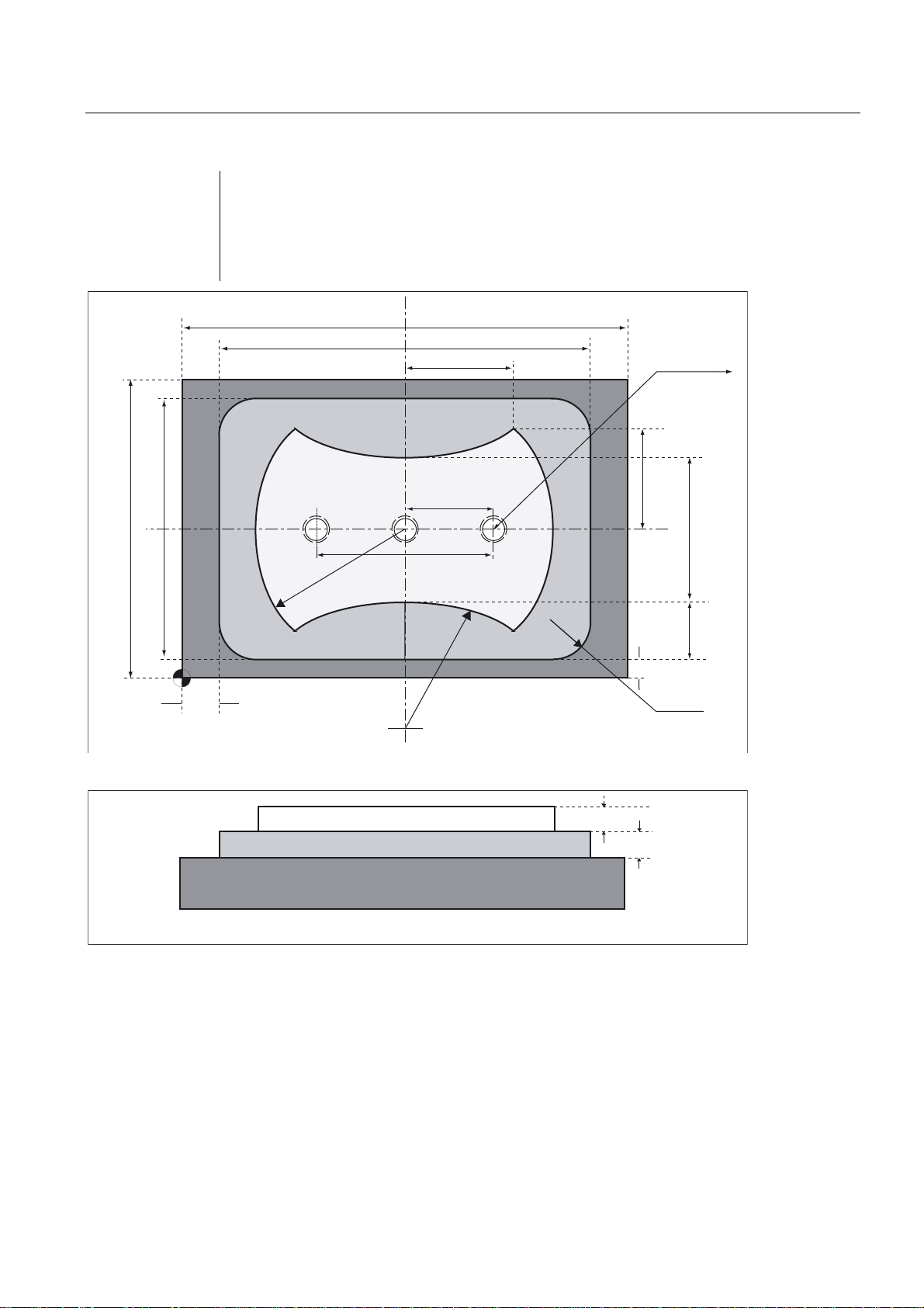
Fundamental Principles of NC Programming
2.5 Second programming example for milling application
N215 X4.25 ;Drill third hole
N220 MCALL
N221 SUPA Z0 D0 M5 M9 ;Delete modal call. Z axis traverses to ;machine
N225 SUPA X0 Y0
MSG ()
N230 M30 ;End of program
5
;Drill second hole
zero
;'3
'LPHQVLRQVDUHLQLQFKHV
6LGHYLHZ
'LPHQVLRQVLQLQFKHV
5
5
Dimension drawing of workpiece "The Raised Boss" (not to scale).
Fundamentals
Programming Manual, 10.2004 Edition, 6FC5 298-7AB00-0BP1
2-25
Page 72

Fundamental Principles of NC Programming
2.6 Programming example for turning application
2.6 Programming example for turning application
Radius programming and tool radius compensation
The sample program contains radius programming and tool radius compensation.
Programming example
%_N_1001_MPF
N5 G0 G53 X280 Z380 D0 ;Start point
N10 TRANS X0 Z250 ;Zero offset
N15 LIMS=4000 ;Speed limitation (G96)
N20 G96 S250 M3 ;Select constant cutting speed
N25 G90 T1 D1 M8 ;Select tool and offset
N30 G0 G42 X-1.5 Z1 ;Activate tool with tool radius compensation
N35 G1 X0 Z0 F0.25
N40 G3 X16 Z-4 I0 K-10 ;Rotate radius 10
N45 G1 Z-12
N50 G2 X22 Z-15 CR=3 ;Rotate radius 3
N55 G1 X24
N60 G3 X30 Z-18 I0 K-3 ;Rotate radius 3
N65 G1 Z-20
N70 X35 Z-40
N75 Z-57
N80 G2 X41 Z-60 CR=3 ;Rotate radius 3
N85 G1 X46
N90 X52 Z-63
N95 G0 G40 G97 X100 Z50 M9 ;Deselect tool radius compensation and approach
N100 T2 D2 ;Call up tool and select offset
N105 G96 S210 M3 ;Select constant cutting speed
N110 G0 G42 X50 Z-60 M8 ;Activate tool with tool radius compensation
N115 G1 Z-70 F0.12 ;Rotate diameter 50
N120 G2 X50 Z-80 I6.245 K-5 ;Rotate radius 8
N125 G0 G40 X100 Z50 M9 ;Retract tool and deselect tool radius
N130 G0 G53 X280 Z380 D0 M5 ;Move to tool change location
N135 M30 ;Program end
tool change location
compensation
Fundamentals
2-26 Programming Manual, 10.2004 Edition, 6FC5 298-7AB00-0BP1
Page 73
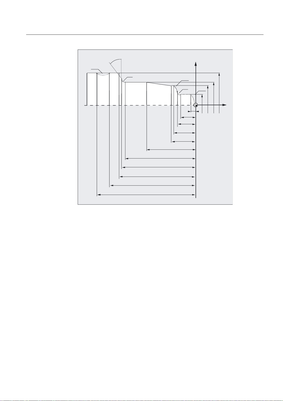
Fundamental Principles of NC Programming
2.6 Programming example for turning application
5
r
5
5
5
;
5
=
Machine manufacturer
The MD settings must be defined correctly before the program can run on the machine.
References: /FB/ Functional description, K2, "Axes, Coordinate Systems,.."
Fundamentals
Programming Manual, 10.2004 Edition, 6FC5 298-7AB00-0BP1
2-27
Page 74

Page 75

Positional Data
3.1 General notes
3.1.1 Program dimensions
In this section you will find descriptions of the commands, with which you can directly
program dimensions taken from a drawing. This has the advantage that no extensive
calculations have to be made for NC programming.
Note
The commands described in this section stand in most cases at the start of a NC program.
The way, in which these functions are combined, is not intended to be a patent remedy. For
example, the choice of working plane may be made at another point in the NC program.
The real purpose of this and all the following sections is to illustrate the conventional
structure of an NC program.
3
Overview of typical dimensions
The basis of most NC programs is a drawing with concrete dimensions.
When implementing in a NC program, it is helpful to take over exactly the dimensions of a
workpiece drawing into the machining program. These can be:
• Absolute dimension, G90 modally effective applies for all axes in the block, up to
revocation by G91 in a following block.
• Absolute dimension, X=AC(value) only this value applies only for the stated axis and is
not influenced by G90/G91. This is possible for all axes and also for SPOS, SPOSA
spindle positionings, and interpolation parameters I, J, K.
• Absolute dimension, X=CC(value) directly approaching the position by the shortest route,
only this value applies only for the stated rotary axis and is not influenced by G90/G91. Is
also possible for SPOS, SPOSA spindle positionings.
• Absolute dimension, X=ACP(value) approaching the position in positive direction, only
this value is set for the rotary axis, the range of which is set in the machine datum to 0...<
360°.
Fundamentals
Programming Manual, 10.2004 Edition, 6FC5 298-7AB00-0BP1
3-1
Page 76

Positional Data
3.2 Absolute/relative dimensions
• Absolute dimension, X=ACN(value) approaching the position in negative direction, only
this value is set for the rotary axis, the range of which is set in the machine datum to 0...<
360°.
• Incremental dimension, G91 modally effective applies for all axes in the block, until it is
revoked by G90 in a following block.
• Incremental dimension, X=IC(value) only this value applies exclusively for the stated axis
and is not influenced by G90/G91. This is possible for all axes and also for SPOS,
SPOSA spindle positionings, and interpolation parameters I, J, K.
• Inch dimension, G70 applies for all linear axes in the block, until revoked by G71 in a
following block.
• Metric dimension, G71 applies for all linear axes in the block, until revoked by G70 in a
following block.
• Inch dimension as for G70, but applies also for feedrate and length-related setting data.
• Metric dimension as for G71, but applies also for feedrate and length-related setting data.
• Diametral programming, DIAMON on
• Diametral programming, DIAMOF off
Diametral programming, DIAM90 for traversing blocks with G90. Radius programming for
traversing blocks with G91.
3.2 Absolute/relative dimensions
3.2.1 Absolute dimension (G90, X=AC)
Function
With the G90 command or the non-modal statement AC you determine the descriptive
system for approaching individual axes from setpoints in absolute dimensions.
You program where the tool should travel.
Programming
G90
Or
X=AC(...) Y=AC(...) Z=AC(...)
Fundamentals
3-2 Programming Manual, 10.2004 Edition, 6FC5 298-7AB00-0BP1
Page 77
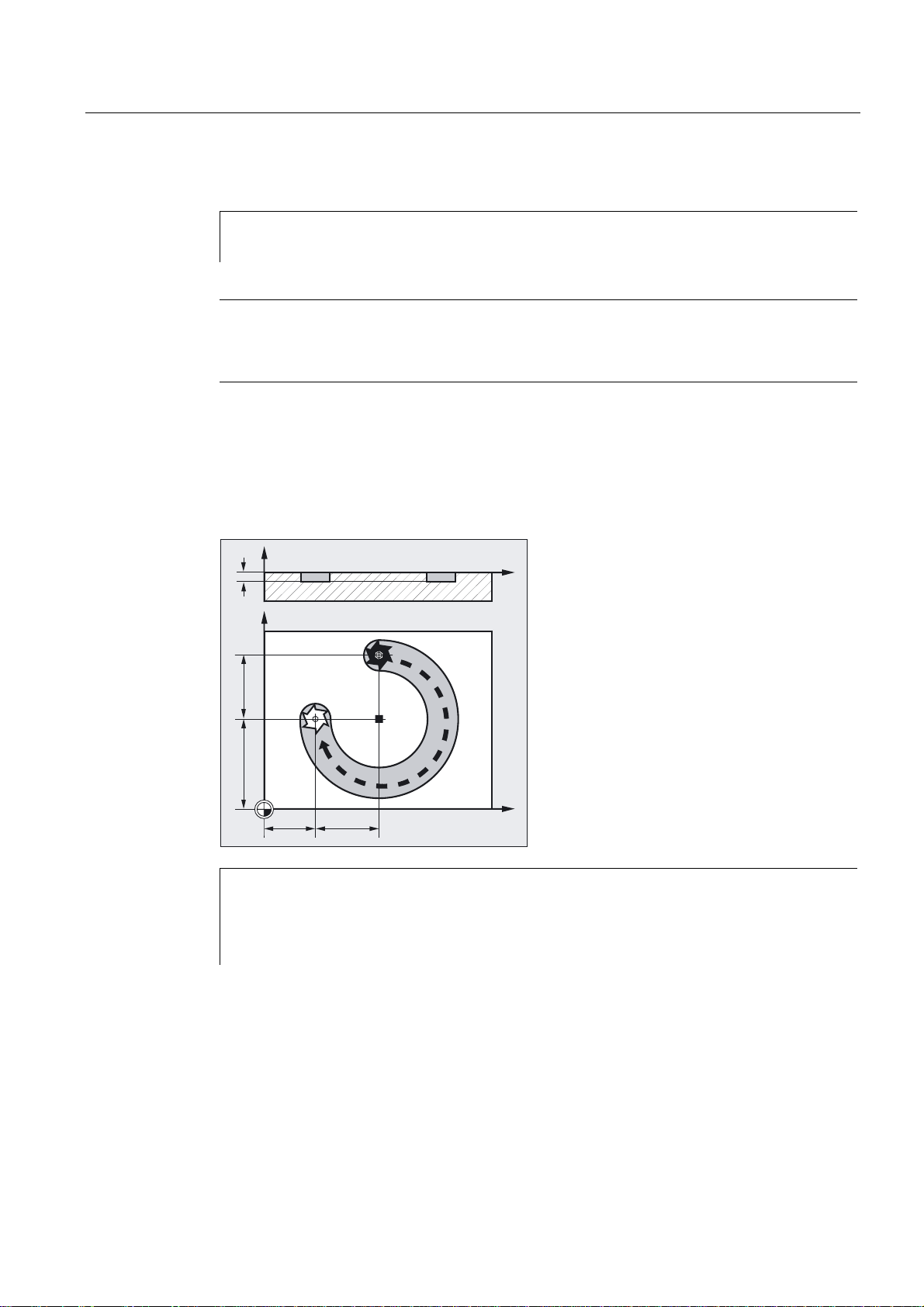
Positional Data
3.2 Absolute/relative dimensions
Parameters
G90 Absolute reference dimension
X Y Z Axis identifiers of the axes to be
AC Absolute dimensions non-modally effective
traversed
Note
The command G90 is modal.
Generally G90 applies to all axes programmed in subsequent NC blocks.
Example of milling
The traverse paths are entered in absolute coordinates with reference to the workpiece zero.
For entering the circle center point coordinates I and J see circle interpolation G2/G3.
=
<
;
N10 G90 G0 X45 Y60 Z2 T1 S2000 M3 ;Absolute dimensioning, rapid traverse to
N20 G1 Z-5 F500 ;Tool infeed at feedrate
N30 G2 X20 Y35 I=AC(45) J=AC(35) ;Circle center point in absolute
N40 G0 Z2 ;Retracting
N50 M30 ;End of block
Fundamentals
Programming Manual, 10.2004 Edition, 6FC5 298-7AB00-0BP1
;
;XYZ, tool, spindle on
;clockwise
dimensions
3-3
Page 78
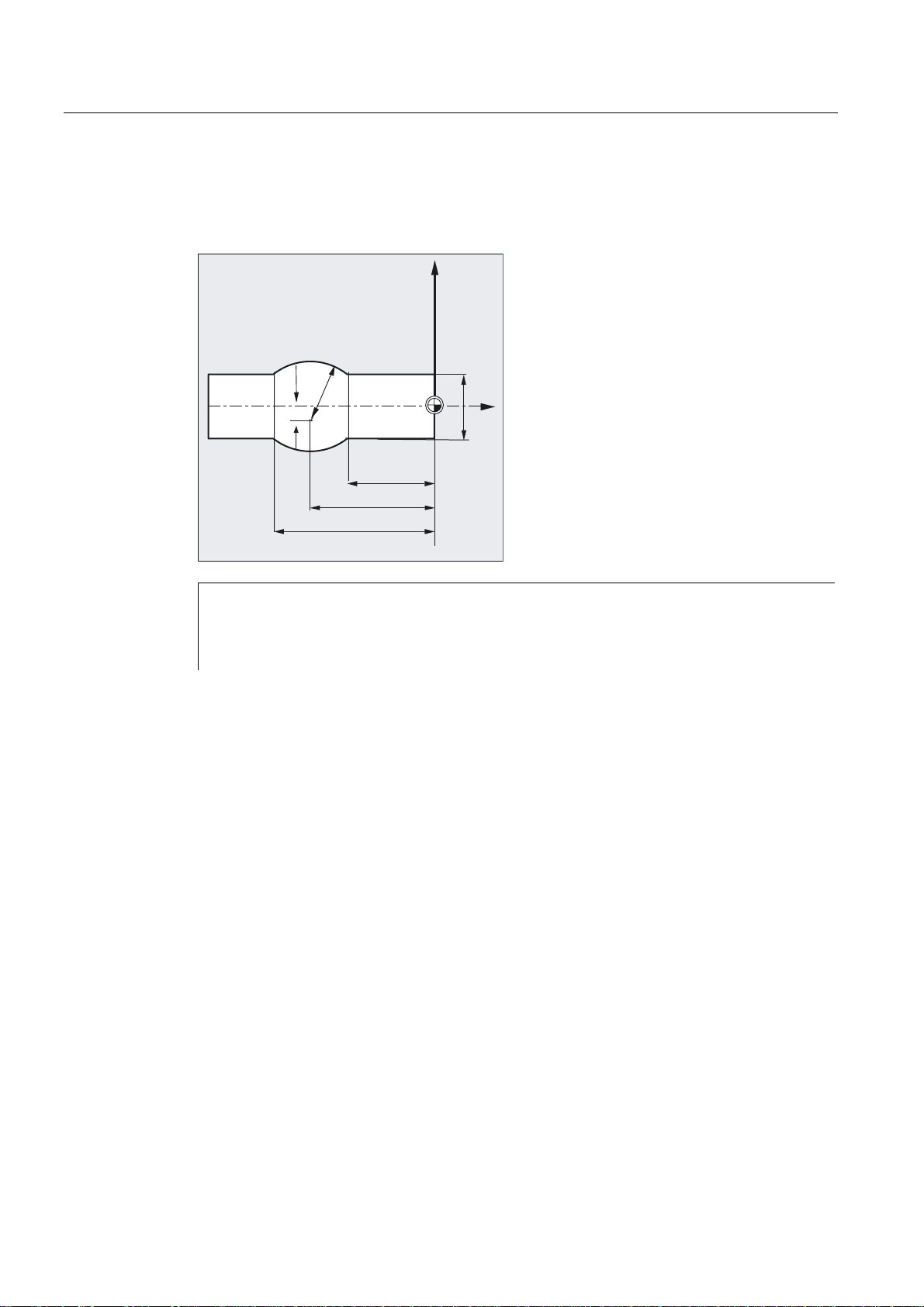
Positional Data
3.2 Absolute/relative dimensions
Example of turning
The traverse paths are entered in absolute coordinates with reference to the workpiece zero.
For entering the circle center point coordinates I and J see circle interpolation G2/G3.
;
N5 T1 D1 S2000 M3 ;Tool, spindle on clockwise
N10 G0 G90 X11 Z1 ;Absolute dimensioning, rapid traverse
N20 G1 Z-15 F0.2 ;Tool infeed at feedrate
N30 G3 X11 Z-27 I=AC(-5) K=AC(-21) ;Circle center point in absolute
N40 G1 Z-40 ;Retracting
Description
Absolute dimensions, G90
The dimensions refer to the origin of the active coordinate system. You program the point to
which the tool is to travel, e.g. in the workpiece coordinate system.
=
:
;to position XYZ
dimensions
Non-modal absolute dimensioning AC
When G91 is active, AC can be used to allow entry of incremental dimensions for individual
axes in a specific block.
Fundamentals
3-4 Programming Manual, 10.2004 Edition, 6FC5 298-7AB00-0BP1
Page 79
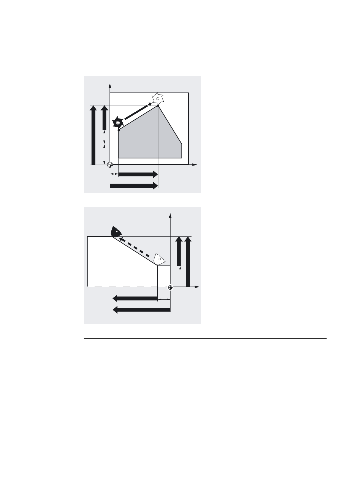
Positional Data
3.2 Absolute/relative dimensions
Milling:
<
*
*
*
*
;
Turning:
;
*
*
=
*
*
Note
On conventional turning machines it is standard practice to interpret incremental NC blocks
in the transverse axis as radius values, while diameter dimensions are valid for absolute
coordinates. This conversion for G90 is performed using the commands DIAMON, DIAMOF
or DIAM90.
For dimensioning for diameter or radius see
Circular interpolation, G2/G3
Fundamentals
Programming Manual, 10.2004 Edition, 6FC5 298-7AB00-0BP1
3-5
Page 80
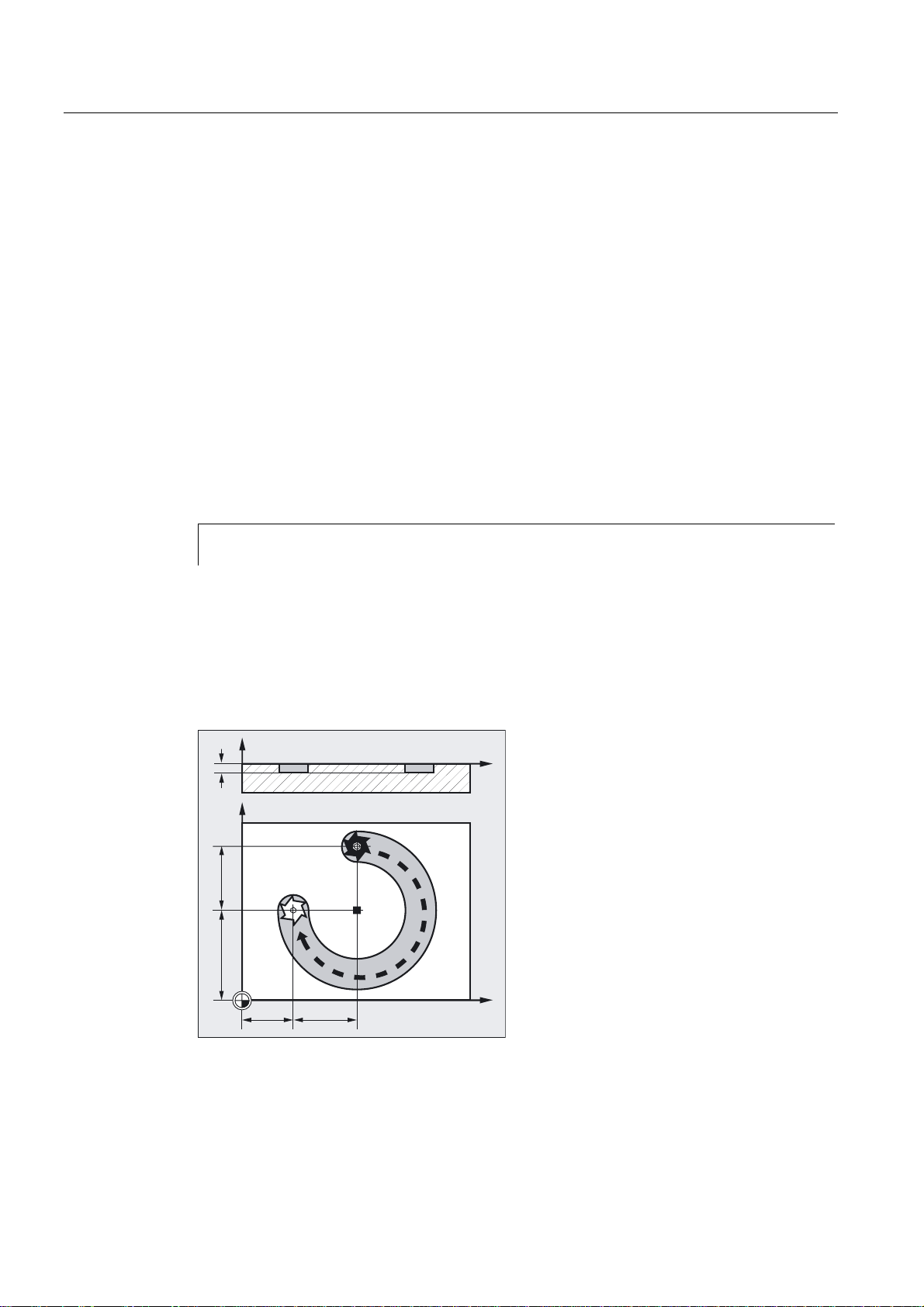
Positional Data
3.2 Absolute/relative dimensions
3.2.2 Incremental dimensions (G91, X=IC)
Function
With the G91 command or the non-modal statement IC, you determine the descriptive
system for approaching individual axes from setpoints in incremental dimensions.
You program how far the tool is to travel.
Programming
G91
Or
X=IC(...) Y=IC(...) Z=IC(...)
Parameters
G91 Relative incremental dimensioning
X Y Z Axis identifiers of the axes to be traversed
=IC Incremental dimensions non-modally effective
Example of milling
The dimensions refer to the last point approached.
The circle center point coordinates of the circle interpolation are stated non-modally in
absolute coordinates, since as default the circle center point is independent of G91.
For entering the circle center point coordinates I and J see circle interpolation G2/G3.
=
<
;
;
Fundamentals
3-6 Programming Manual, 10.2004 Edition, 6FC5 298-7AB00-0BP1
Page 81
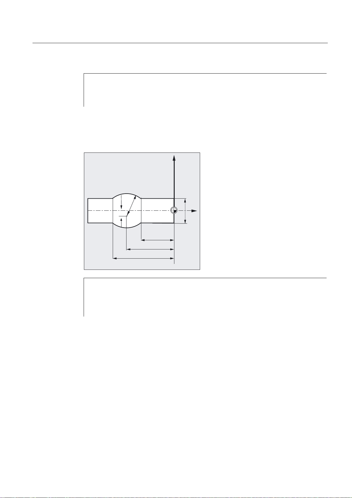
Positional Data
3.2 Absolute/relative dimensions
N10 G90 G0 X45 Y60 Z2 T1 S2000 M3 ;Absolute dimensioning, rapid traverse to
N20 G1 Z-5 F500 ;Tool infeed at feedrate
N30 G2 X20 Y35 I0 J-25) ;Circle center point in incremental
N40 G0 Z2 ;Retracting
N50 M30 ;End of block
Example of turning
The dimensions refer to the last point approached.
For entering the circle center point coordinates I and J see circle interpolation G2/G3.
;
;XYZ, tool, spindle on clockwise
dimensions
:
=
N5 T1 D1 S2000 M3 ;Tool, spindle on clockwise
N10 G0 G90 X11 Z1 ;Absolute dimensioning, rapid traverse to
N20 G1 Z-15 F0.2 ;Tool infeed at feedrate
N30 G3 X11 Z-27 I-8 K-6 ;Circle center point in incremental
N40 G1 Z-40 ;Retracting
N50 M30 ;End of block
;position XYZ
dimensions
Fundamentals
Programming Manual, 10.2004 Edition, 6FC5 298-7AB00-0BP1
3-7
Page 82
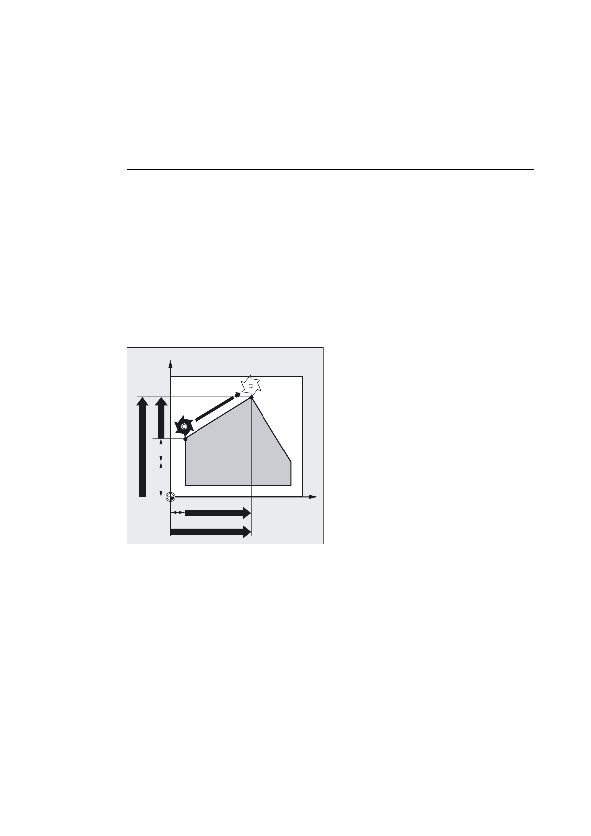
Positional Data
3.2 Absolute/relative dimensions
Example without traversing through the active zero offset
• G54 contains an offset of 25 in X
• SD 42440: FRAME_OFFSET_INCR_PROG = 0
N10 G90 G0 G54 X100
N20 G1 G91 X10 ;Traverse X by 10 mm, the offset is
N30 G90 X50 ;Traverse to position X75, the offset
Description
The dimensions refer to the last point approached. You program how far the tool is to travel.
Non-modally effective incremental dimensioning IC
Using IC and with a predefined absolute G90 dimension the incremental dimensioning can
be set non-modally for individual axes.
Milling:
;not traversed
;is traversed
*
<
*
*
;
*
Fundamentals
3-8 Programming Manual, 10.2004 Edition, 6FC5 298-7AB00-0BP1
Page 83
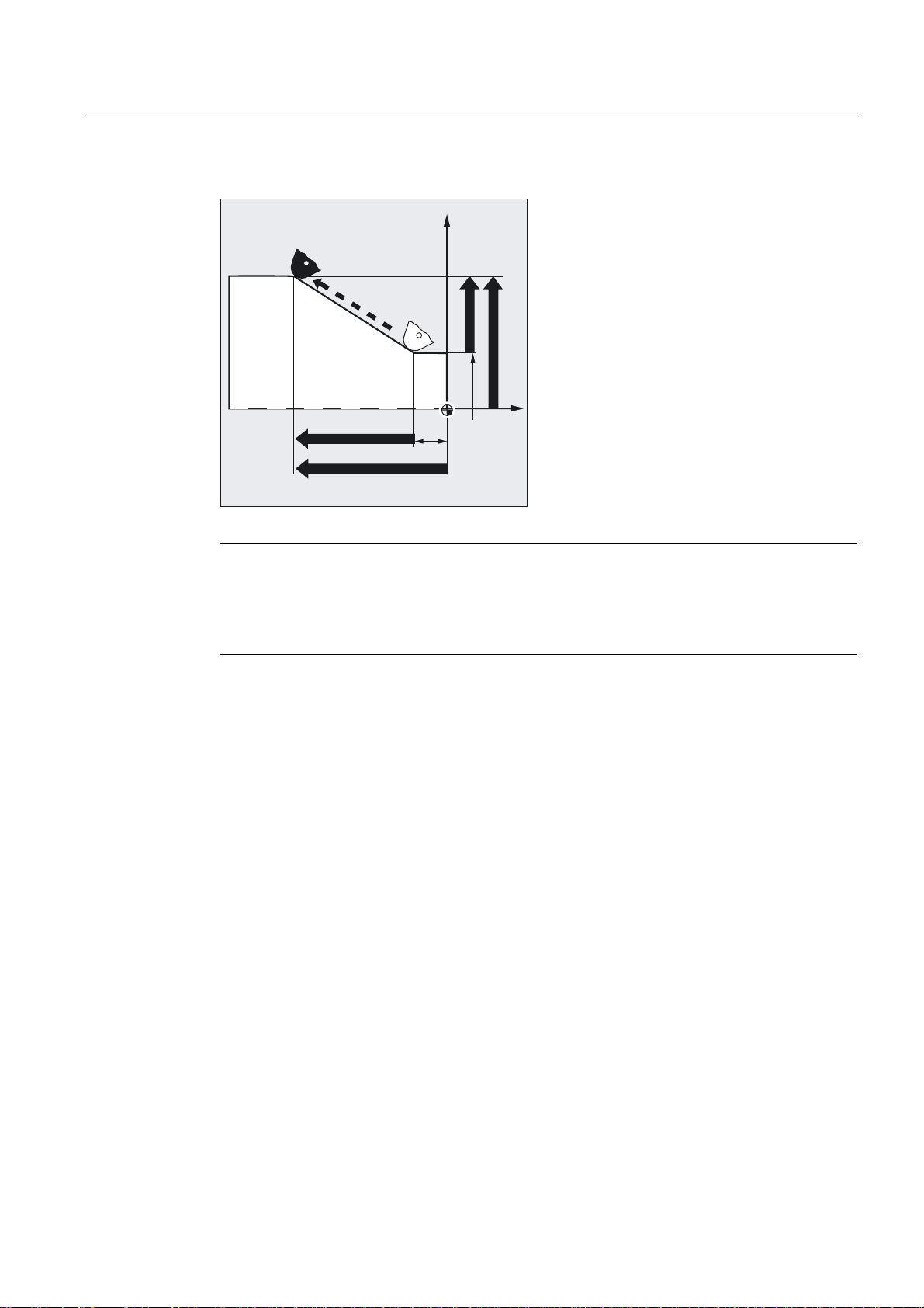
Positional Data
3.2 Absolute/relative dimensions
Turning:
;
*
*
=
*
*
G91 extension
Note
On conventional turning machines it is standard practice to interpret incremental NC blocks
in the transverse axis as radius values, while diameter dimensions are valid for absolute
coordinates. This conversion for G91 is performed using the commands DIAMON, DIAMOF
or DIAM90.
For dimensioning for diameter or radius see circular interpolation G2/G3.
For applications such as scratching, it is necessary only to traverse the path programmed in
the incremental coordinates. The active zero offset or tool offset is not traversed. This can be
set separately using setting data.
Incremental dimensioning without traversing through the active tool offset
The active tool offset is not traversed if the setting datum
SD 42442: TOOL_OFFSET_INCR_PROG = 0.
Incremental dimensioning without traversing through the active zero offset
The active zero offset is not traversed if the setting datum
SD 42440: FRAME_OFFSET_INCR_PROG = 0
Fundamentals
Programming Manual, 10.2004 Edition, 6FC5 298-7AB00-0BP1
3-9
Page 84
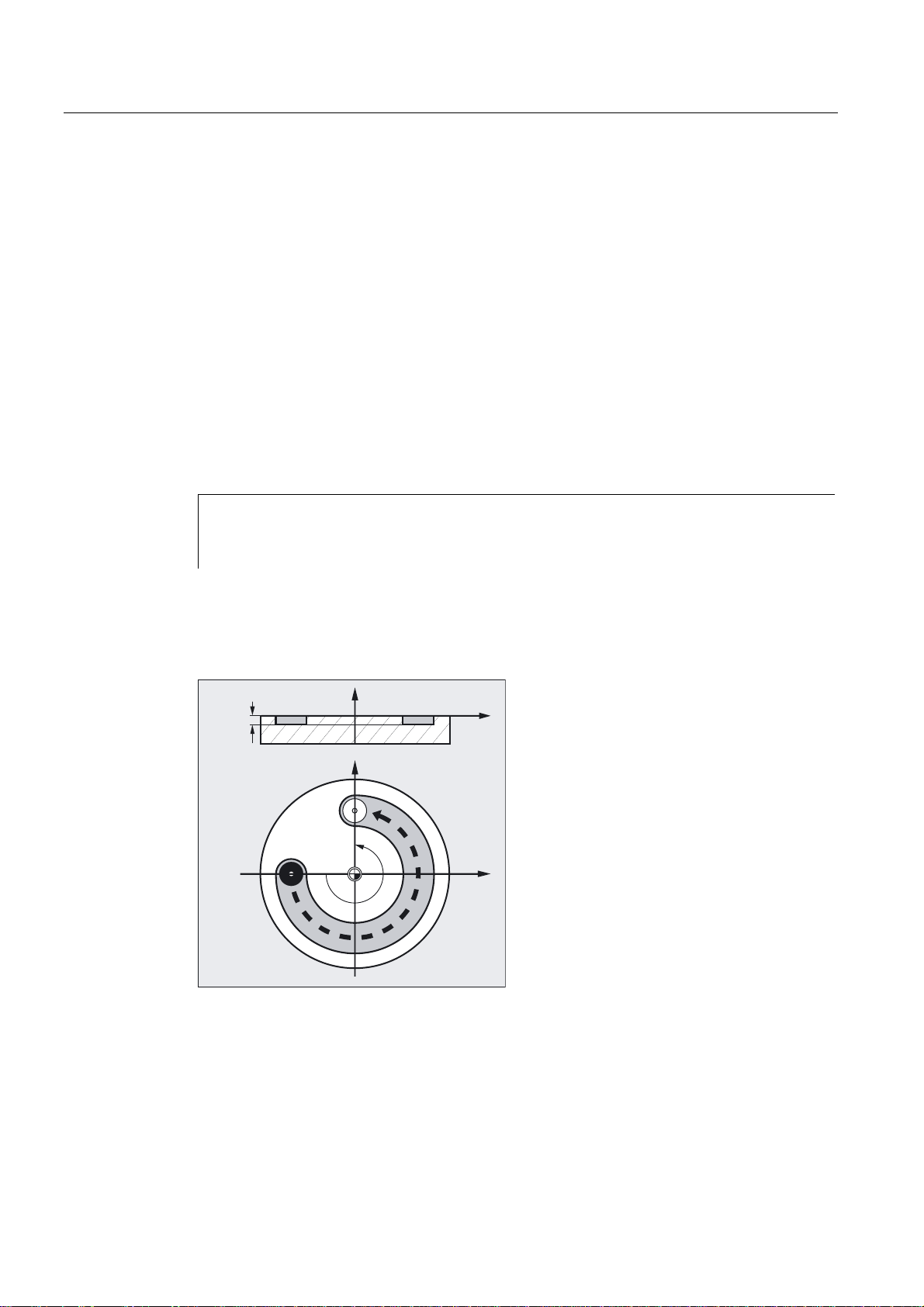
Positional Data
3.3 Absolute dimension for rotary axes (DC, ACP, ACN)
3.3 Absolute dimension for rotary axes (DC, ACP, ACN)
With the above parameters you can define the desired approach strategy for positioning
rotary axes.
Programming
A=DC(…) B=DC(…) C=DC(…)
Or
A=ACP(…) B=ACP(…) C=ACP(…)
Or
A=ACP(…) B=ACP(…) C=ACP(…)
Parameters
A B C Axis identifier for rotary axis to be traversed
DC Absolute dimensions, approach position directly
ACP Absolute dimensions, approach position in positive
ACN Absolute dimensions, approach position in negative
direction
direction
Example of milling
Machining on a rotary table: The tool is stationary, the table rotates through 270° in
clockwise direction. to produce a circular groove.
=
<
r
;
;
Fundamentals
3-10 Programming Manual, 10.2004 Edition, 6FC5 298-7AB00-0BP1
Page 85
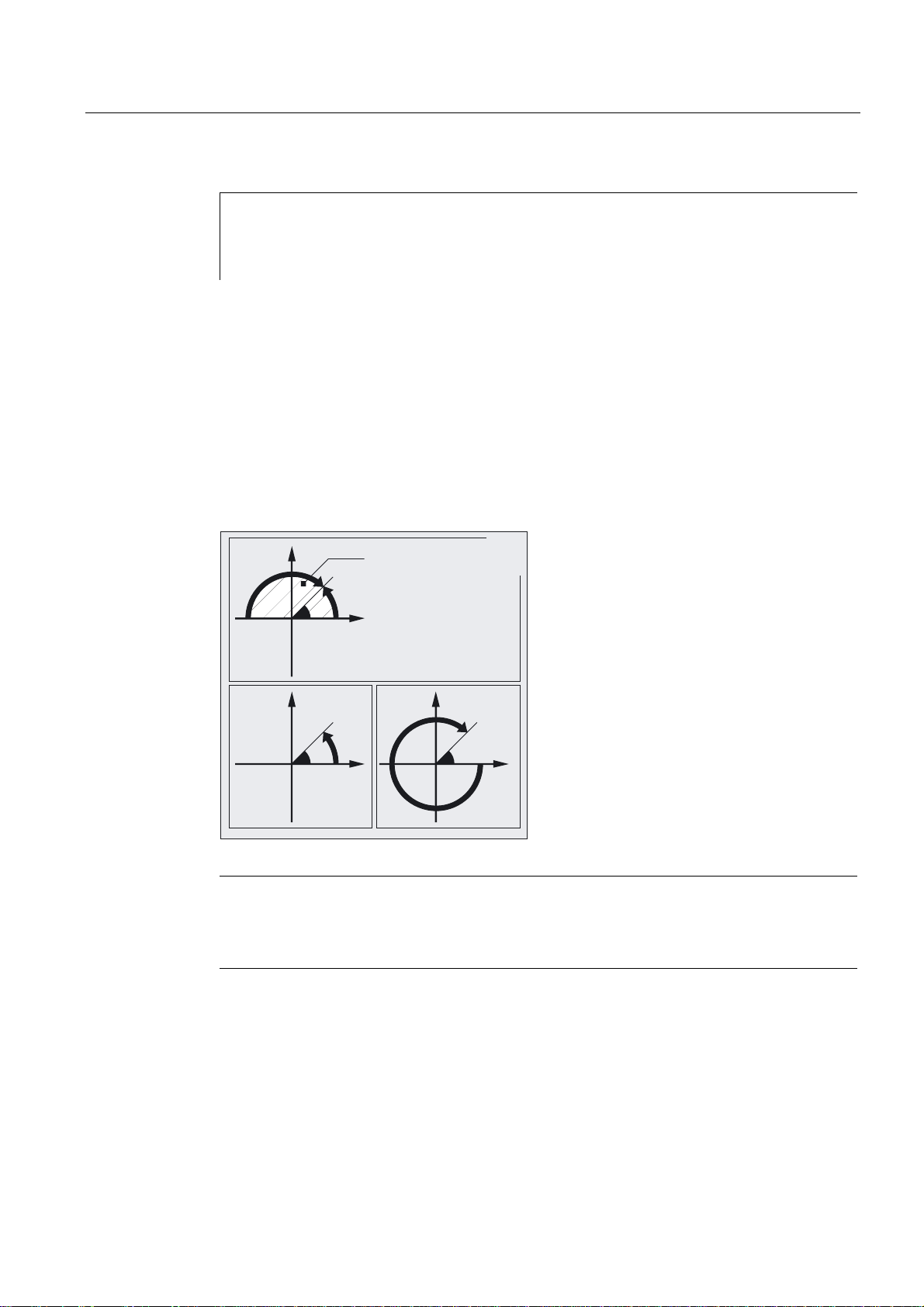
Positional Data
3.3 Absolute dimension for rotary axes (DC, ACP, ACN)
N10 SPOS=0 ;Spindle in position control
N20 G90 G0 X-20 Y0 Z2 T1 ;Absolute, infeed in rapid traverse
N30 G1 Z-5 F500 ;Lower at feedrate
N40 C=ACP(270) ;The table rotates through 270° in
N50 G0 Z2 M30 ;Lift, end of program
Absolute dimensioning with DC
The rotary axis travels to the position programmed in absolute coordinates along the shortest
direct path. The rotary axis traverses across an area of up to 180°.
Absolute dimensioning with ACP
The rotary axis travels to the positions programmed in absolute coordinates in the positive
direction of axis rotation (counterclockwise).
Absolute dimensioning with ACN
The rotary axis travels to the positions programmed in absolute coordinates in the negative
direction of axis rotation (clockwise).
;clockwise direction (positive), the tool
;mills a circular groove
'&
$&3 $&1
0D[LPXP
7UDYHUVLQJUDQJH
Note
The traversing range must be set to between 0° and 360° in the machine data (modulo
method) for positioning with directional data (ACP, ACN). To traverse modulo rotary axes by
more than 360° in a block, G91 or IC must be programmed.
The positive direction of rotation (clockwise or counterclockwise) is set in the machine data.
Fundamentals
Programming Manual, 10.2004 Edition, 6FC5 298-7AB00-0BP1
3-11
Page 86

Positional Data
3.4 Dimensions inch/metric, (G70/G700, G71/G710)
All of the commands are non-modal.
You can also use DC, ACP and ACN for spindle positioning from zero speed.
Example: SPOS=DC(45)
3.4 Dimensions inch/metric, (G70/G700, G71/G710)
Function
Depending on the dimensions in the production drawing, you can program workpiece
geometries alternately in metric measurements and inches.
Programming
Call-up
G70 or G71
G700 or G710
Parameters
G700/G710
The functionality of G70/G71 has been extended with G700/G710. In addition to the
geometrical parameters, the technological parameters, such as feed F, are interpreted
during parts program execution in the system of units set in G700/G710.
The controller interprets all feedrates used with G700/G710 in the programmed system of
units, unlike G70/G71.
The programmed feedrate value is modal and thus does not change automatically on
subsequent G70/G71/G700/G710 selections.
Example of milling
Change between metric and imperial input with basic setting metric (G70/G71).
G70 Imperial measure (length [inches])
G71 Metric dimensions (length [mm])
G700 Imperial measure (length [inch]; feedrate [inch/min])
G710 Metric dimensions (length [mm]; feedrate F [mm/min])
Fundamentals
3-12 Programming Manual, 10.2004 Edition, 6FC5 298-7AB00-0BP1
Page 87
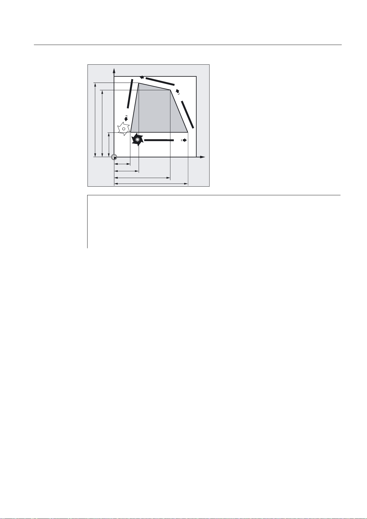
Positional Data
3.4 Dimensions inch/metric, (G70/G700, G71/G710)
<
*
* *
Description
*
;
G70
;is active until deselected by G71 or
;end of program
program
N10 G0 G90 X20 Y30 Z2 S2000 M3 T1 ;Basic setting metric
N20 G1 Z-5 F500 ;At feedrate in Z [mm/min]
N30 X90
N40 G70 X2.75 Y3.22 ;Enter destination positions in inches,
N50 X1.18 Y3.54
N60 G71 X 20 Y30 ;Enter positions in mm
N70 G0 Z2 M30 ;Retract in rapid traverse, end of
G70 or G71
You can instruct the control to convert the following geometrical dimensions (with necessary
deviations) into the system of units not set and enter them directly:
Examples
• Positional data X, Y, Z, ...
• Intermediate point coordinates I1, J1, K1
Interpolation parameters I, J, K and circle radius
CR in circle programming
• Thread lead (G34, G35)
• Programmable zero offset (TRANS)
• Polar radius RP
Fundamentals
Programming Manual, 10.2004 Edition, 6FC5 298-7AB00-0BP1
3-13
Page 88

Positional Data
3.4 Dimensions inch/metric, (G70/G700, G71/G710)
Further information
All other parameters such as feedrates, tool offsets or settable zero offsets are interpreted
(when using G70/G71) in the default system of units (MD 10240:
SCALING_SYSTEM_IS_METRIC).
The representation of system variables and machine data is also independent of the
G70/G71 context.
If the feedrate in the G70/G71/G700/G710 context is to be activated, a new F value must be
programmed explicitly.
All length-related NC data, machine data and setting data for G700/G710 are always read
and written in the programmed context of G700/G710.
References:/FB1/, Description of Functions, Basic Machine, G2 section "Metric/inch
measuring system"
Synchronized actions
If positioning tasks are performed in synchronized actions and no G70/G71/G700/G710
command is programmed in the synchronized action itself, the G70/G71/G700/G710 context
active at the time of execution determines which system of units is used.
References:/PGA/ Programming Guide, Advanced, Section "Movement Synchronized
Actions".
/FBSY/ , Description of Functions, Synchronized Actions
Fundamentals
3-14 Programming Manual, 10.2004 Edition, 6FC5 298-7AB00-0BP1
Page 89
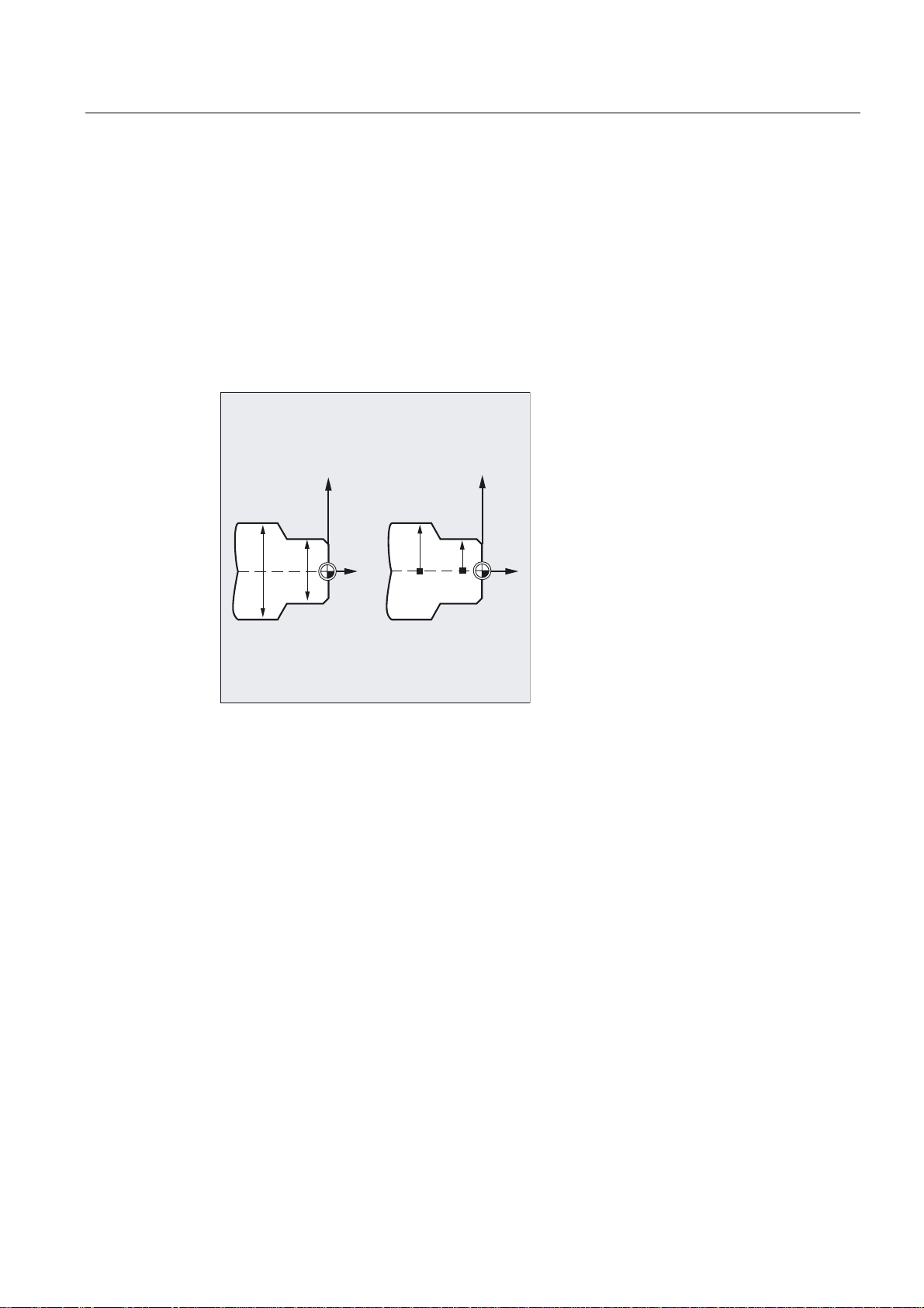
Positional Data
3.5 Special turning functions
3.5 Special turning functions
3.5.1 Dimensions for radius, diameter, (DIAMON, DIAMOF, DIAM90)
Function
The free choice of diameter or radius dimensions allows you to program the dimensions
straight from the engineering drawing without conversion.
Programming
',$021
'
;
:
'
',$02)
=
5
;
:
5
=
After power up of
• DIAMON/DIAM90, diameter dimensions are defined for the specified transverse axis. as
diameter.
• DIAM90 is displayed as a diameter, irrespective of the traversing method (G90/G91) the
actual value of the transverse axis. This also applies to reading of actual values in the
workpiece coordinate system with MEAS, MEAW, $P_EP[x] and $AA_IW[x].
DIAMON
Or
DIAMOF
Or
DIAM90
Fundamentals
Programming Manual, 10.2004 Edition, 6FC5 298-7AB00-0BP1
3-15
Page 90

Positional Data
3.5 Special turning functions
Parameters
Absolute dimensioning (G90) Incremental dimensioning
DIAMON Diameter Diameter
DIAMOF Radius (for default, see
DIAM90 Diameter Radius
The diameter programming is set with DIAM90 for G90 and
machine manufacturer)
the radius programming for G91.
Further information
The commands for diameter and radius data are modal.
By programming DIAMOF you can switch at any time to radius as dimension.
Diameter values (DIAMON/DIAM90)
Diameter values apply to the following data:
• Actual-value display of transverse axis in the workpiece coordinate system
• JOG mode: Increments for incremental dimension and travel with handwheel
• Programming:
End positions, independent of G90/G91 interpolation parameters inG2/G3, if these are
programmed with AC absolutely
(G91)
Radius
Example
• Actual values read in the workpiece coordinate system in
MEAS, MEAW, $P_EP[X], $AA_IW[X] (see PGA, Programming Guide "Advanced")
N10 G0 X0 Z0 Approach starting point
N20 DIAMOF Diameter input off
N30 G1 X30 S2000 M03 F0.7 X axis = transverse axis; radius
N40 DIAMON Diameter dimensions active
N50 G1 X70 Z-20 Traverse to diameter position X70 and
N60 Z-30
N70 DIAM90 Diameter programming for absolute
N80 G91 X10 Z-20 Incremental dimension
N90 G90 X10 Absolute dimensions
N100 M30 ; End of program
dimensions active
Traverse to radius position X30
Z–20
dimensions and radius programming for
incremental dimensions
Fundamentals
3-16 Programming Manual, 10.2004 Edition, 6FC5 298-7AB00-0BP1
Page 91
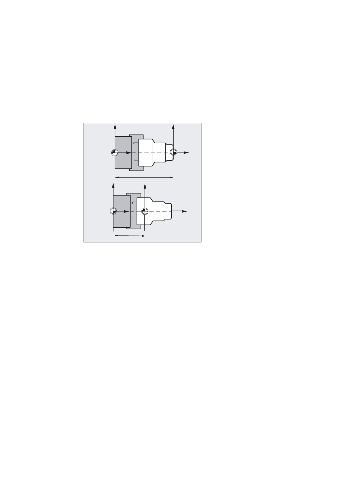
Positional Data
3.5 Special turning functions
3.5.2 Position of workpiece
Function
While the machine zero is fixed, you can choose the position for the workpiece zero on the
longitudinal axis. The workpiece zero is generally located on the front or rear side of the
workpiece.
:RUNSLHFH
]HUR
IURQW
:RUNSLHFH
]HUR
UHDU
;
0DFKLQH
0
**RU75$16
;
0DFKLQH
0
**
RU75$16
;
:RUNSLHFH
;
:RUNSLHFH
:
=
:RUNSLHFH
=
=
:RUNSLHFH
Zero points
Both the machine zero and the workpiece zero are positioned on the center of rotation. The
settable offset on the X axis is thus zero.
coordinate system
The dimensions for the transverse axis are generally specified as diameter measurements
(double path dimension as compared to other axes).
The geometry axis to be used as a transverse axis is defined in machine data.
Fundamentals
Programming Manual, 10.2004 Edition, 6FC5 298-7AB00-0BP1
3-17
Page 92
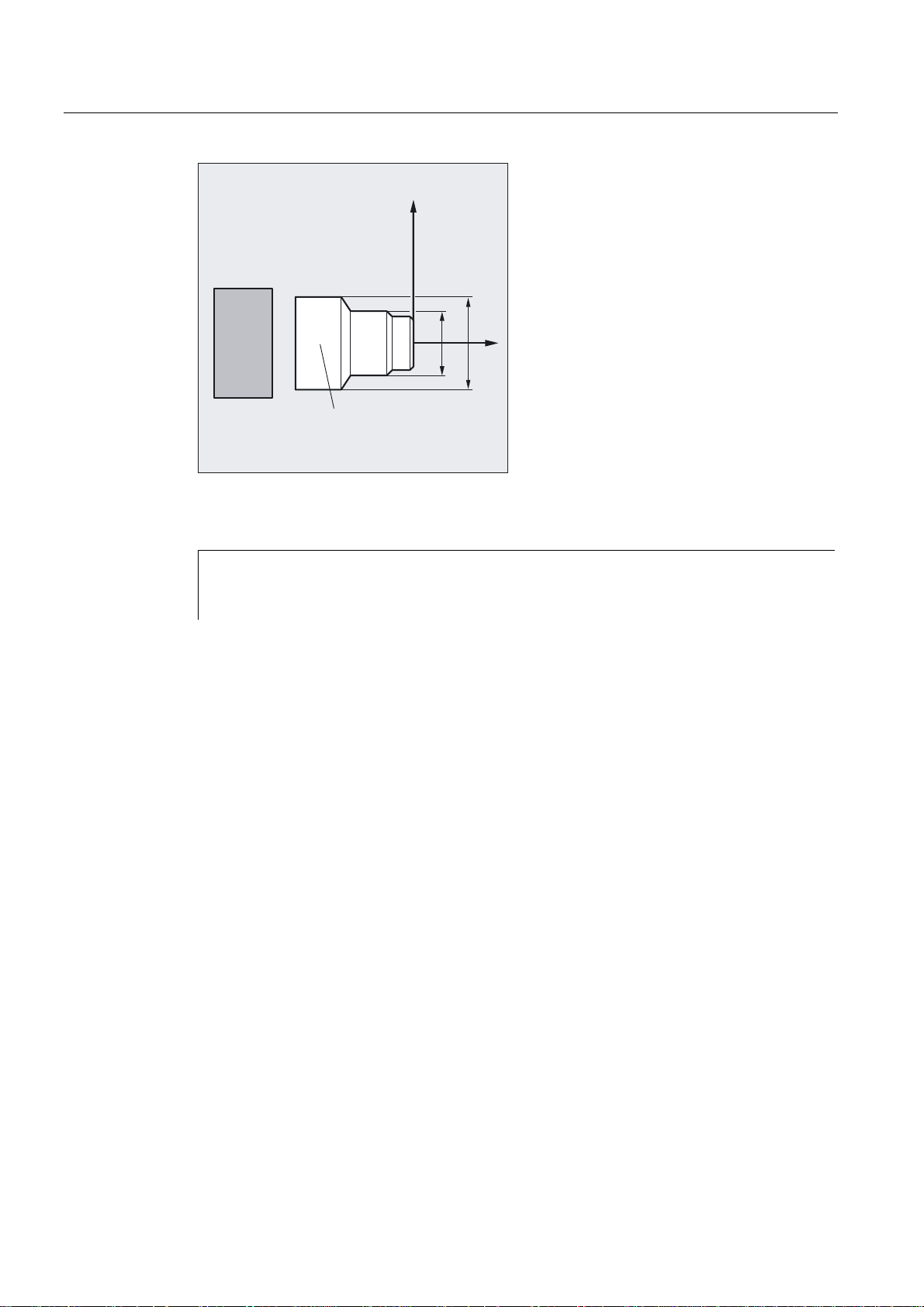
Positional Data
3.5 Special turning functions
;
7UDQVYHUVHD[LV
Parameters
0
/RQJLWXGLQDOD[LV
:
=
'
'
G54 to G599 or TRANS Call for the position of the workpiece zero
M Machine zero
W Tool zero point
Z axis Longitudinal axis
X axis Transverse axis
The two mutually perpendicular geometry axes are usually designated as follows:
• Longitudinal axis= Z axis (abscissa)
• Transverse axis= X axis (ordinate)
Fundamentals
3-18 Programming Manual, 10.2004 Edition, 6FC5 298-7AB00-0BP1
Page 93
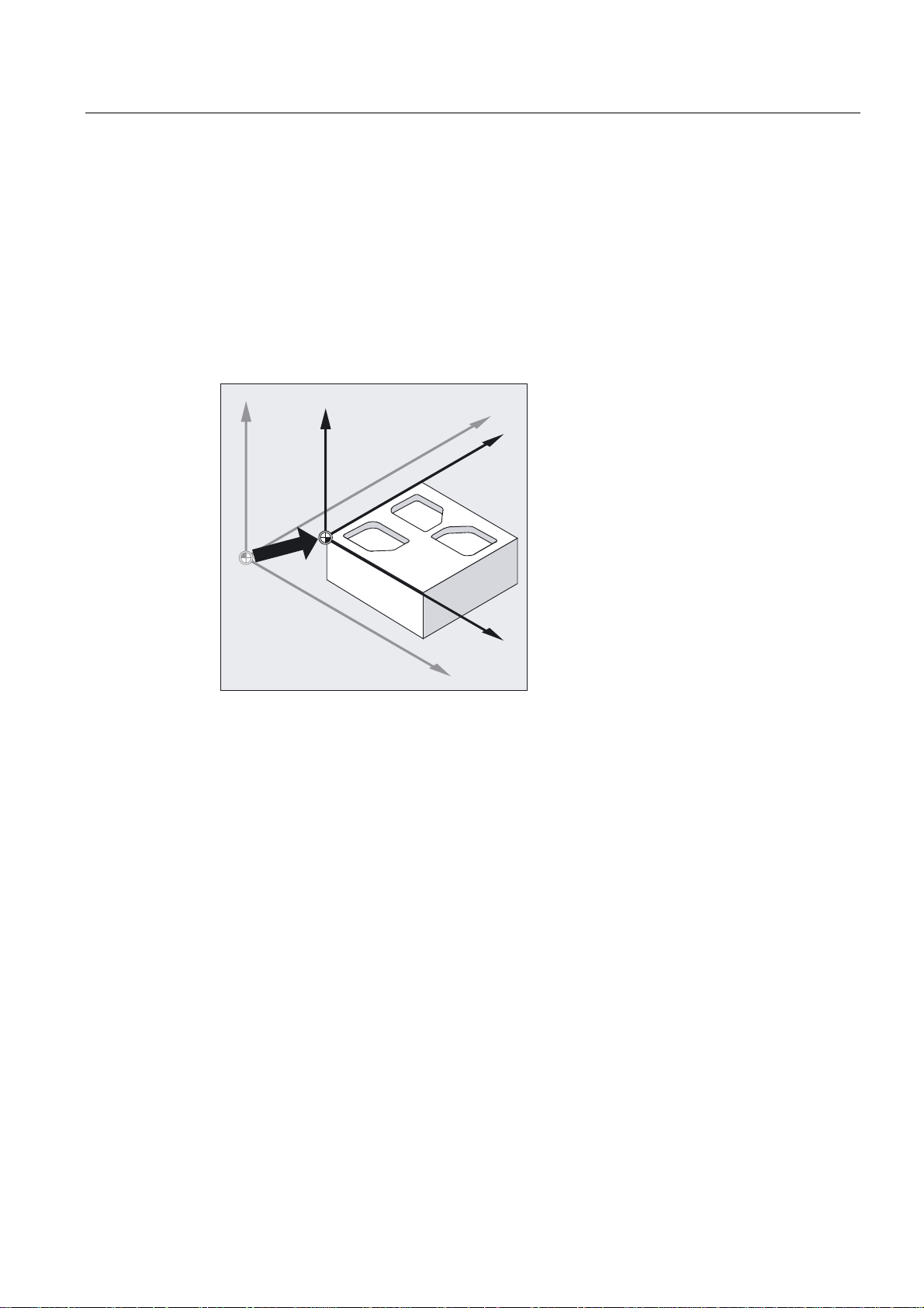
Positional Data
3.6 Zero offset (frame), G54 to G57, G505 to G599, G53, G500/SUPA
3.6 Zero offset (frame), G54 to G57, G505 to G599, G53, G500/SUPA
Function
The settable zero offset relates the workpiece zero on all axes to the origin of the basic
coordinate system.
It is, therefore, possible to call up cross-program zero points for different fixtures with a G
command.
Milling:
=
*
=
<
<
;
;
For turning, for example, the offset value for tightening the chuck is entered in G54.
Fundamentals
Programming Manual, 10.2004 Edition, 6FC5 298-7AB00-0BP1
3-19
Page 94
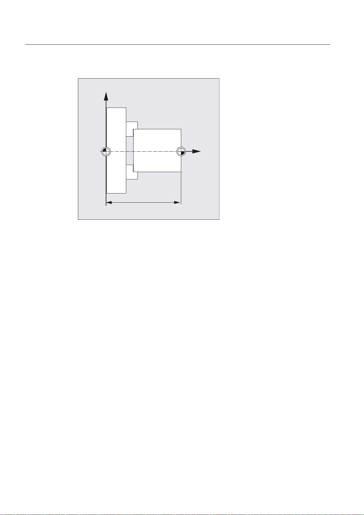
Positional Data
3.6 Zero offset (frame), G54 to G57, G505 to G599, G53, G500/SUPA
Turning:
;
=
Programming
0
Call-up
G54
Or
G55
Or
G56
Or
G57
Or
G505 … G599
Switching off
G53
Or
G500
Or
SUPA
Or
G153
:
*
Fundamentals
3-20 Programming Manual, 10.2004 Edition, 6FC5 298-7AB00-0BP1
Page 95

Positional Data
3.6 Zero offset (frame), G54 to G57, G505 to G599, G53, G500/SUPA
Parameters
G54 to G57 Call the second to fifth settable zero offset/frame
G505 ...G599 Call the 6th to the 99th settable zero offset
G53 Non-modal deactivation of current settable zero offset and
G500 G500=zero frame, default setting,
SUPA Non-modal deactivation, including programmed offsets,
G153 Non-modal suppression of settable, programmable and total
For more information please refer to Frame section.
Offset of the zero in the Cartesian coordinate system by frames such as
• Programmable zero offset, e.g., TRANS, ATRANS
• Programmable rotations, e.g., ROT, AROT
programmable zero offset
(contains no offset, rotation, mirroring or scaling)
Deactivation of settable zero offsets/frames (G54 to G599)
until the next call.
Activation of the total basic frame ($P_ACTBFRAME).
G500 is not 0
Activation of first settable zero offset/frames
($P_UIFR[0]) and
Activation of total basic frame ($P_ACTBFRAME), or a
modified basic frame is activated.
handwheel offsets (DRF), external zero offset and PRESET
offset.
basic frame
Example
• Programmable scalings, e.g., SCALE, ASCALE
• Programmable mirrorings, e.g., MIRROR, AMIRROR
In this example, three workpieces, arranged on a pallet according to the zero offset values
G54 to G56, are machined successively. The machining sequence is programmed in
subprogram L47.
Fundamentals
Programming Manual, 10.2004 Edition, 6FC5 298-7AB00-0BP1
3-21
Page 96
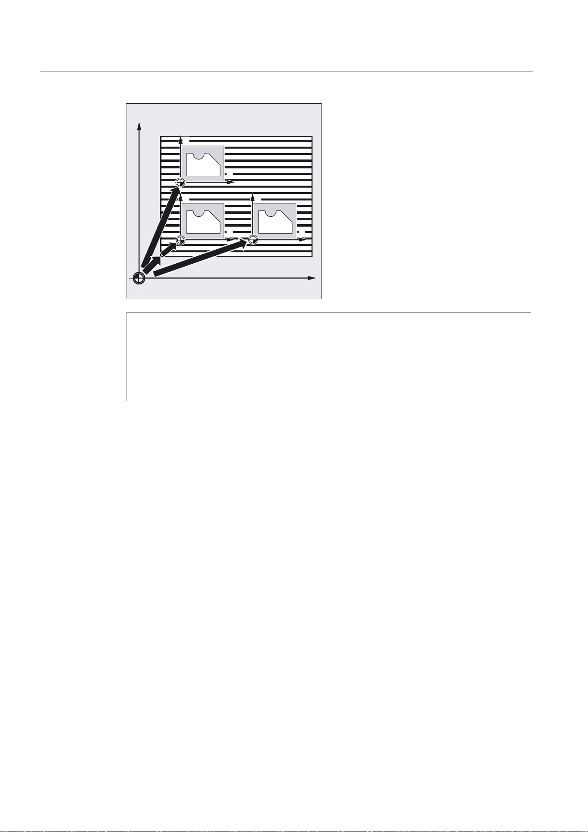
Positional Data
3.6 Zero offset (frame), G54 to G57, G505 to G599, G53, G500/SUPA
<
0
<
;
Description
<
*
*
*
75$16;0
<
;
;
;
0
N10 G0 G90 X10 Y10 F500 T1 ;Approach
N20 G54 S1000 M3 ;Call the first zero offset,
N30 L47 ;Run program, in this case as a
N40 G55 G0 Z200 ;Call the second zero offset
N50 L47 ;Run program as subprogram
N60 G56 ;Call third zero offset
N70 L47 ;Run program as subprogram
N80 G53 X200 Y300 M30 ;Suppress zero offset, ;end of program
;spindle clockwise
subprogram
;Z via obstacle
Setting the offset values
On the operator panel or universal interface, enter the following values in the internal control
zero offset table:
• Coordinates for the offset
• Angle for rotated clamping and
• Scale factors if necessary
Fundamentals
3-22 Programming Manual, 10.2004 Edition, 6FC5 298-7AB00-0BP1
Page 97
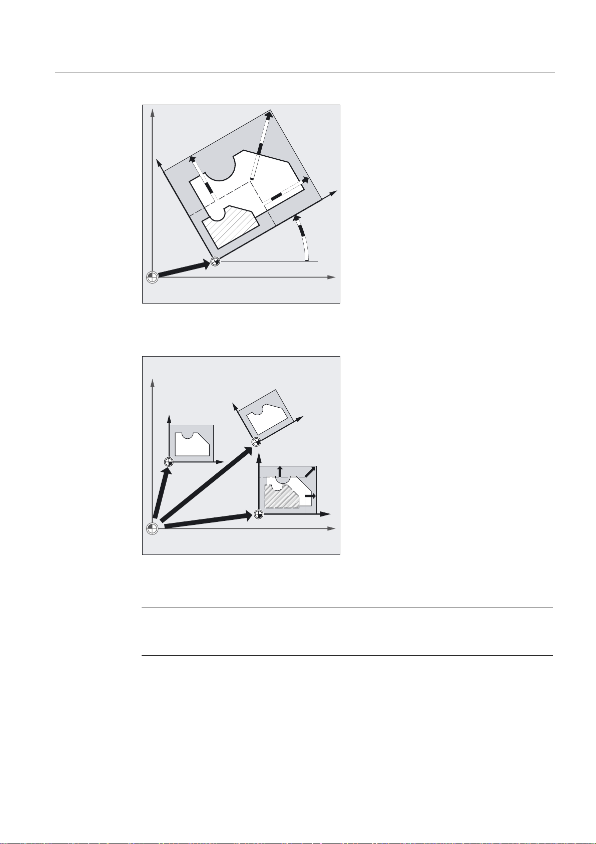
Positional Data
3.6 Zero offset (frame), G54 to G57, G505 to G599, G53, G500/SUPA
<
6FDOLQJ
<
;
5RWDWH
2II FVHW
;
Switching on zero offset, G54 to G57
In the NC program, the zero offset is moved from the machine coordinate system to the
workpiece coordinate system by executing one of the four commands G54 to G57.
<
<
<
;
<
;
;
;
In the next NC block with a programmed movement, all of the positional parameters and thus
the tool movements refer to the workpiece zero, which is now valid.
Note
The 4 available zero offsets can be used, for example, for multiple machining operations, to
describe 4 workpiece clamping positions simultaneously and execute them in the program.
Fundamentals
Programming Manual, 10.2004 Edition, 6FC5 298-7AB00-0BP1
3-23
Page 98

Positional Data
3.6 Zero offset (frame), G54 to G57, G505 to G599, G53, G500/SUPA
Further settable zero offsets, G505 to G599
Command numbers G505 to G599 are available for this purpose. This enables you to create
up to 100 settable zero offsets in total, in addition to the 4 default zero offsets G54 to G57,
by using the machine data. They are stored in the zero point memory.
Deactivating a zero offset
Command G500 activates the first settable zero offset including basic offset, i.e., when zero
frame is selected as the default, the current settable zero offset is deactivated.
G53 suppresses the programmable and settable offset modally.
G153 has the same effect as G53 and also suppresses the total basic frame.
SUPA has the same effect as G153 and also suppresses the DRF offset, overlaid motions,
and external ZOs.
Note
The basic setting at program start, e.g., G54 or G500, can be set with machine data.
You will find more information on programmable zero offsets in the Frames section
"Programmable zero offset".
Fundamentals
3-24 Programming Manual, 10.2004 Edition, 6FC5 298-7AB00-0BP1
Page 99
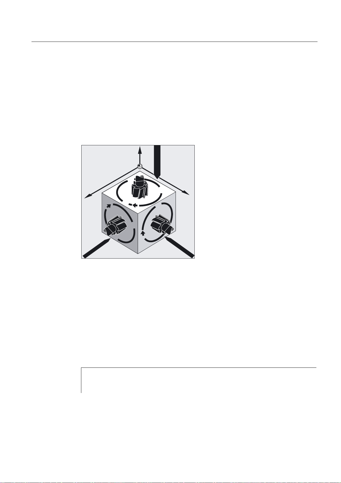
Positional Data
3.7 Selection of working plane (G17 to G19)
3.7 Selection of working plane (G17 to G19)
Function
By specification of working plane, in which the contour is to be machined also defines the
following functions:
• The plane for tool radius compensation.
• The infeed direction for tool length compensation depending on the tool type.
• The plane for circular interpolation.
=
,QIHHG
Programming
;
,QIHHG
Call-up
G17
Or
G18
Or
G19
*
*
<
*
,QIHHG
Parameters
G17 Working plane X/Y
G18 Working plane Z/X
G19 Working plane Y/Z
Fundamentals
Programming Manual, 10.2004 Edition, 6FC5 298-7AB00-0BP1
Infeed direction Z Plane selection 1st - 2nd geometry axis
Infeed direction Y Plane selection 3rd - 1st geometry axis
Infeed direction X Plane selection 2nd - 3rd geometry axis
3-25
Page 100

Positional Data
3.7 Selection of working plane (G17 to G19)
Important
In the basic setting, preset for millingG17 (X/Y plane) and G18 (Z/X plane) for turning.
With selection of the tool path compensationG41/G42 (see section "Tool offsets") the
working plane must be specified so that the control can correct the tool length and radius.
Example for milling
The "conventional" approach with milling tool:
• define working plane (G17 basic setting for milling),
• select tool type (T) and tool offset values (D),
• switch on path compensation (G41),
• program traversing movements.
N10 G17 T5 D8 ;G17 selection of the working plane, here
N20 G1 G41 X10 Y30 Z-5 F500 The radius compensation is performed in
N30 G2 X22.5 Y40 I50 J40 Circular interpolation / tool radius
X/Y T,
;D tool selection. The length
compensation is performed in the Z
direction
the X/Y plane.
compensation in the X/Y plane.
Description
It is advisable to define the working plane G17 to G19 at the beginning of the program. In the
basic setting the Z/X plane is preset for turning G18
Fundamentals
3-26 Programming Manual, 10.2004 Edition, 6FC5 298-7AB00-0BP1
 Loading...