

Siemens SINUMERIK 810D, SINUMERIK 810DE, SINUMERIK 810D powerline, SINUMERIK 810DE powerline Configuration Manual
RGB ELEKTRONIKA AGACIAK CIACIEK
SPÓŁKA JAWNA
Jana Dlugosza 2-6 Street
51-162 Wrocław
Poland
biuro@rgbelektronika.pl
+48 71 325 15 05
www.rgbautomatyka.pl
www.rgbelektronika.pl
DATASHEET
www.rgbautomatyka.pl
www.rgbelektronika.pl
OTHER SYMBOLS:
6FC 3541-0AA-Z
SIEMENS
YOUR
PARTNER IN
MAINTENANCE
At our premises in Wrocław, we have a fully equipped servicing facility. Here we perform all the repair
works and test each later sold unit. Our trained employees, equipped with a wide variety of tools and
having several testing stands at their disposal, are a guarantee of the highest quality service.
OUR SERVICES
ENCODERS
SERVO
DRIVERS
LINEAR
ENCODERS
SERVO AMPLIFIERS
CNC
MACHINES
MOTORS
POWER
SUPPLIERS
OPERATOR
PANELS
CNC
CONTROLS
INDUSTRIAL
COMPUTERS
PLC
SYSTEMS
Repair this product with RGB ELEKTRONIKA
ORDER A DIAGNOSIS
∠
Buy this product at RGB AUTOMATYKA
BUY
∠
Manual 11/2002 Edition
Hardware Configuration
SINUMERIK 810D

Valid for
Control Software Version
SINUMERIK 810D 3
SINUMERIK 810DE (export version) 3
SINUMERIK 810D powerline 6
SINUMERIK 810DE powerline 6
1 1.2002 Edition
SINUMERIK 810D
Hardware Configuration
Manual
System Overview 1
Installation Conditions 2
Design and Installation 3
Description 4
Axis Expansion 5
I/O Modules 6
NCU Terminal Block 7
DMP Compact Modules 8
Maintenance and Service 9
Abbreviations A
References B
EC Declaration of
Conformity
C
Index
SINUMERIKRDocumentation
Printing history
Brief details of this edition and previous editions are listed below .
The status of each edition is shown by the code in the “Remarks” columns.
Status code in the “Remarks” column:
A New documentation......
B Unrevised reprint with new order no......
C Revised edition with new status......
If factual changes have been made on the page within the same
software version, this is indicated by a new edition coding in the
header on that page.
Edition Order No. Remarks
12.95 6FC5 297-1AD10-0BP0 A
07.96 6FC5 297-1AD10-0BP1 C
08.97 6FC5 297-2AD10-0BP0 C
12.98 6FC5 297-3AD10-0BP0 C
08.99 6FC5 297-3AD10-0BP1 C
04.00 6FC5 297-3AD10-0BP2 C
10.00 6FC5 297-4AD10-0BP0 C
12.01 6FC5 297-4AD10-0BP1 C
03.02 6FC5 297-6AD10-0BP0 C
1 1.02 6FC5 297-6AD10-0BP1 C
This manual is included in the documentation available on CD--ROM (DOCONCD)
Edition Order No. Remarks
1 1.02 6FC5 298-6CA00-0BG3 C
Trademarks
SIMATICr,SIMATIC HMIr, SIMATIC NETr,SIROTECr, SINUMERIKr and SIMODRIVEr are registered
trademarksof Siemens AG. Otherproduct names used in this documentation may be trademarks which, if
used by thirdparties,could infringe the rightsof their owners.
Further information is available on the Internet under:
http://www.ad.siemens.de/sinumerik
This publication was produced with Interleaf V7.
The reproduction, transmission or use of this document or its
contents is not permitted without express written authority. Offenders
will be liable for damages. All rights, including rights created by patent
grant or registration of a utility model or design, are reserved.
E Siemens AG, 1995--2002. All rights reserved
Other functions not described in this documentation might be
executable in the control. However, no claim can be made regarding
the availability of these functions when the equipment is first supplied
or for service cases.
We have checked that the contents of this document correspond to
the hardware and software described. Nonetheless, differences might
exist. The information contained in this document is, however,
reviewed regularly and any necessary changes will be included in the
next edition. We welcome suggestions for improvement.
Subject to change without prior notice
Siemens Aktiengesellschaft
Order No. 6FC5 297-6AD10-0BP1
Printed in Germany
v
E Siemens AG, 2002. All rights reserved
SINUMERIK 810D Manual Hardware Configuration (PHC) -- 11.02 Edition
Preface
SINUMERIK documentation is split into three levels:
S General Documentation
S User Documentation
S Manufacturer/Service Documentation.
For more detailed information on SINUMERIK810D publications and other pu-
blicationscovering all the SINUMERIK controls, please contact your local SIE-
MENS office.
You will also requirethe following
References: /PJU/ SIMODRIVE Planning Guide
As from 12.2001,
S SINUMERIK 810D powerline and
S SINUMERIK 810DE powerline
are available with improved performance. A listof the available powerline
modules can be found in the hardware description:
References: /PHC/ ConfigurationManual SINUMERIK 810D
Armed with the information contained in this manual,itis possible to install the
SINUMERIK 810D numerical control and take measures to maintain and ser-
vice it.
If you have any questions, please call the following hotline:
A&D TechnicalSupport Phone: +49(0)180-5050-222
Fax: +49(0)180-5050-223
Email:adsupport@siemens.com
For questions about the documentation(suggestionsfor improvement,correc-
tions) please send a fax to the following number or send an email:
Fax: +49 (0)9131 98 -- 2176
E-- mail: motioncontrol.docu@erl.siemens.de
Fax form: see feedback page at the end of this publication.
Internet address http://www.ad.siemens.de/sinumerik
S Project planning engineers, electriciansand fitters
S Service and operating personnel.
Notes for the
reader
SINUMERIK 810D
powerline
Subject matter of
this manual
Hotline
Who is this
manual intended
for?
12.95
vi
E Siemens AG, 2002. All rights reserved
SINUMERIK 810D Manual Hardware Configuration (PHC) -- 11.02 Edition
The following notices are intendedfirstly for your personal safety and secondly
to prevent damage occurring to the products described or any connected
devices and machines.
!
Warning
When operating electrical devices, it is impossible to avoidapplying hazardous
voltages to certain parts of the equipment.
Afterall power has been cut off, there will still be dangerous voltages present in
the intermediatecircuitof all SIMODRIVE modules fora further 5 minutes!
See operating instructions.
Unqualifiedoperatoractionof the device/system or failure to observethe war-
ning notices may resultin serious physical injury or material damage. Only
suitably qualifiedpersonnel trainedin assembling, installing,activating or
operatingthe product, should operate thisdevice/system.
Should measurements or tests need to be carriedout on theactive device, it is
importantto comply with the definitions and implementation instructionsof acci-
dent prevention regulation VBG 4.0, in particular§ 8 ”Permissible differences
when working on active components”. Suitable electric tools should be used.
!
Danger
This warning notice indicates thatdeath,serious physical injury or considerable
materialdamage will occur if the relevant safety precautions are not taken.
!
Warning
This warning notice indicates thatdeath,serious physical injury or considerable
materialdamage may occur if the relevant safety precautions are not taken.
!
Caution
This warning notice (with warning triangle) indicates that slight physical injury or
some material damage may occur if the relevant safety precautions are not
taken.
Caution
This warning notice (without a warningtriangle) indicates that some material
damage may occur if the relevant safety precautions are not taken.
Danger notices
Additional notices
P
l
a
nningGuide SINUMERI
K
8
10D
P
ref
a
ce
12.95
vii
E Siemens AG, 2002. All rights reserved
SINUMERIK 810D Manual Hardware Configuration (PHC) -- 11.02 Edition
Atention
This warning notice indicates that an unwelcome event or unwanted situation
may occur if the relevant notices are ignored.
!
Important
This notice indicates that there is an important issue to be considered.
Note
This notice indicates that itthereis a further issue to be considered.
!
Warning
S Repairs to devices thathave been supplied by our company must only be
carriedout by SIEMENS Customer Service or by repair centers author-
ized by SIEMENS.When replacing parts or components,only use those
parts that are included in the spare parts list.
S Before opening the device,always disconnect the powersupply.
S EMERGENCY STOP devices complying with EN 60204 IEC 204 (VDE
0113) must remain effective in all automation equipment modes. Resetting
the EMERGENCY STOP device must not cause an uncontrolled or unde-
fined restart.
S Anywhere in the automationequipmentwhere faults might cause major
materialdamage or even physical injury, in other words, wherefaultscould
be dangerous, additional external precautions must be taken, or facilities
must be provided,that guarantee or enforce a safe operational state, even
when there is a fault (e.g. caused by an independentlimitswitch, mechani-
cal interlocks,etc.).
!
Caution
S Connecting cables and signal lines should be installedso that inductive and
capacitive interference does not in any way impair the automation func-
tions.
P
l
a
nningGuide SINUMERI
K
8
10D
P
ref
a
ce
10.00
12.95
viii
E Siemens AG, 2002. All rights reserved
SINUMERIK 810D Manual Hardware Configuration (PHC) -- 11.02 Edition
!
Warning
Proper transportation, expert storage, installation and mounting, as well as
careful operationand maintenance are essentialforthis device to operate
correctlyand reliably.
If warning notices are ignored,serious physicalinjuryor material damage may
result.
Warning
The modules containelectrostatic sensitive components. Before touching an
electronicmodule,the persons carrying out the work must themselves be
electrostatically discharged. The simplest way of doing this is to touch an
electrically conducting earthed object(e.g.a bare metal part of a switchboard
or a plug socket protective conductor).
P
l
a
nningGuide SINUMERI
K
8
10D
P
ref
a
ce
12.95
ix
E Siemens AG, 2002. All rights reserved
SINUMERIK 810D Manual Hardware Configuration (PHC) -- 11.02 Edition
Electrostatic Sensitive Devices
!
Important
Handling ESD modules:
S When dealing with electrostatic components, make surethat people, work-
places and packaging are well earthed!
S The fundamental principle here is that you should only ever touch electronic
modules if this is unavoidable because work needs to be carriedout. Under
no circumstances should you take hold of printed circuitboards so that you
touch component pins or printed conductors.
S You should only ever touch the units if
-- you are permanently earthed by an ESD armband,
-- you are wearingESD shoes or ESD shoe grounding strips in connection
with an ESD base.
S Modules must only be put on conductive supports (machine table with ESD
layer, conductive ESD foam, ESD packing bag, ESD transport container).
S Do not place modules near to display units, monitors or television sets (mi-
nimum distance to screen > 10 cm).
S Modules must not be brought into contact with chargeable and highly insu-
lating materials, such as plastic sheets, insulating table tops or clothing ma-
de of synthetic fibers.
S Measurements must only be carried out on modules if
-- the measuring instrument is grounded (e.g.by protectiveconductors)or
-- before measuring, with an isolated measuring instrument, the measu-
ring head is briefly discharged (e.g.touching a bare metal control hou-
sing).
The device must only be put to the uses prescribed in the manualand only in
conjunction with third party devices and components recommended or appro-
ved by SIEMENS.
Should any problemsor questions arise while you are using thismanual,please
contact the Siemens office concerned using the form provided at theend of this
manual.
J
ESD notices
Intended use
Contact persons
P
l
a
nningGuide SINUMERI
K
8
10D
P
ref
a
ce
07.96

12.95
x
E Siemens AG, 2002. All rights reserved
SINUMERIK 810D Manual Hardware Configuration (PHC) -- 11.02 Edition
P
l
a
nningGuide SINUMERI
K
8
10D
P
ref
a
ce
Notes
xi
E Siemens AG, 2002. All rights reserved
SINUMERIK 810D Manual Hardware Configuration (PHC) -- 11.02 Edition
1 System Overview 1-13....................................................
1.1 SINUMERIK 810D powerline 1-13..................................
1.2 System configuration 1-14.........................................
1.3 Labeling and adhesive labels 1-23..................................
2 Installation Conditions 2-25...............................................
2.1 Secondary electrical conditions 2-25................................
2.1.1 Electromagnetic compatibility (EMC) 2-26...........................
2.1.2 Power supply 2-27...............................................
2.1.3 Safe electrical isolation 2-29.......................................
2.1.4 Earthing concept 2-31............................................
2.1.5 RI suppression measures 2-32.....................................
2.2 Ambient climatic and mechanical conditions 2-34.....................
2.2.1 Transport and storage conditions 2-34..............................
2.2.2 Operating conditions 2-35.........................................
2.2.3 Exposure to contaminants 2-36....................................
2.3 Technical data of the individual components 2-37.....................
2.4 MPI network 2-38................................................
2.4.1 MPI interconnecting cables 2-38....................................
2.4.2 MPI network rules 2-39...........................................
3 Design and Installation of the 810D 3-41...................................
3.1 Design of the SINUMERIK 810D 3-41...............................
3.2 Installing the SINUMERIK 810D 3-42...............................
3.2.1 Modification for external cooling, 2-axis CCU box (SW 5 and higher) 3-47
3.3 Mains supply (MS) 3-49...........................................
4 Description of the SINUMERIK 810D 4-51..................................
4.1 Components of the SINUMERIK 810D 4-51..........................
4.1.1 Overview 4-51...................................................
4.2 Interfaces of the SINUMERIK 810D 4-54............................
4.2.1 Brief description 4-54.............................................
4.2.2 Hardware interfaces overview 4-55.................................
4.2.3 CCU1/CCU2: Description of the interfaces,
operating and display elements 4-56................................
4.2.4 CCU3: Description of the interfaces, operating and display elements 4-64
4.2.5 Cable distributor 4-66.............................................
4.3 Measuring system 4-69...........................................
4.3.1 Measuring system and motor connection assignments 4-69............
4.3.2 Evaluative encoder systems 4-70...................................
4.3.3 Measuring channels, indirect and direct measuring systems 4-72.......
4.4 Integrated power sections: 3-axis CCU box 4-77......................
4.5 Integrated power sections: 2-axis CCU box 4-79......................
Contents
12.95
xii
E Siemens AG, 2002. All rights reserved
SINUMERIK 810D Manual Hardware Configuration (PHC) -- 11.02 Edition
4.6 PLC module 4-80................................................
4.7 PCMCIA card (memory card) 4-80..................................
4.8 CCU1: 6th axis (SW 3.2 and higher) 4-81............................
5 Axis Expansion 5-83.....................................................
5.1 Axis expansion plug-in unit 5-83....................................
5.2 Axis expansion with the SIMODRIVE 611D
closed-loop control module 5-86....................................
6 I/O Modules 6-89.........................................................
6.1 Single I/O module 6-89............................................
7 NCU Terminal Block 7-97.................................................
8 DMP Compact Modules 8-103..............................................
8.1 DMP compact module 16I (6FC5 111-0CA01-0AA0) 8-103..............
8.2 DMP compact module 16O (6FC5 111-0CA02-0AA1) 8-105............
8.3 DMP compact module 8O (6FC5 111-0CA03-0AA1) 8-107.............
8.4 DMP compact module 1I analog (6FC5 111-0CA04-0AA0) 8-109.........
8.5 DMP compact module 1I NC analog (6FC5 211-0AA10-0AA0) 8-112.....
8.6 DMP compact module 1O analog (6FC5 111-0CA05-0AA0) 8-115........
9 Maintenance and Service 9-117.............................................
9.1 Warning notices 9-117.............................................
9.2 Battery replacement
(6FC5 247-0AA18-0AA0, GWE-570 665 000 101) 9-118................
A Abbreviations A-121.......................................................
B References B-123..........................................................
C EC Declaration of Conformity C-135........................................
D Index Index-139..............................................................
11.02
1-13
E Siemens AG, 2002. All rights reserved
SINUMERIK 810D Manual Hardware Configuration (PHC) -- 11.02 Edition
System Overview
1.1 SINUMERIK 810D powerline
As from 03.2002
S SINUMERIK 810D powerline and
S SINUMERIK 810DE powerline
are ready for delivery.The followingpowerline modules are now available with
enhanced performance:
Table 1-1 powerline modules for SINUMERIK 810D/810DE
Module
Description
CCU3 with additional pulse interface and two machining channels
Note
The SINUMERIK 810D powerline and SINUMERIK 810DE powerline are
suppliedwithSW6.
Earliersystem software versions of the SINUMERIK810D cannot be used on
the
SINUMERIK 810D powerline or SINUMERIK 810DE powerline.
1
12.95
1.2 System configuration
1-14
E Siemens AG, 2002. All rights reserved
SINUMERIK 810D Manual Hardware Configuration (PHC) -- 11.02 Edition
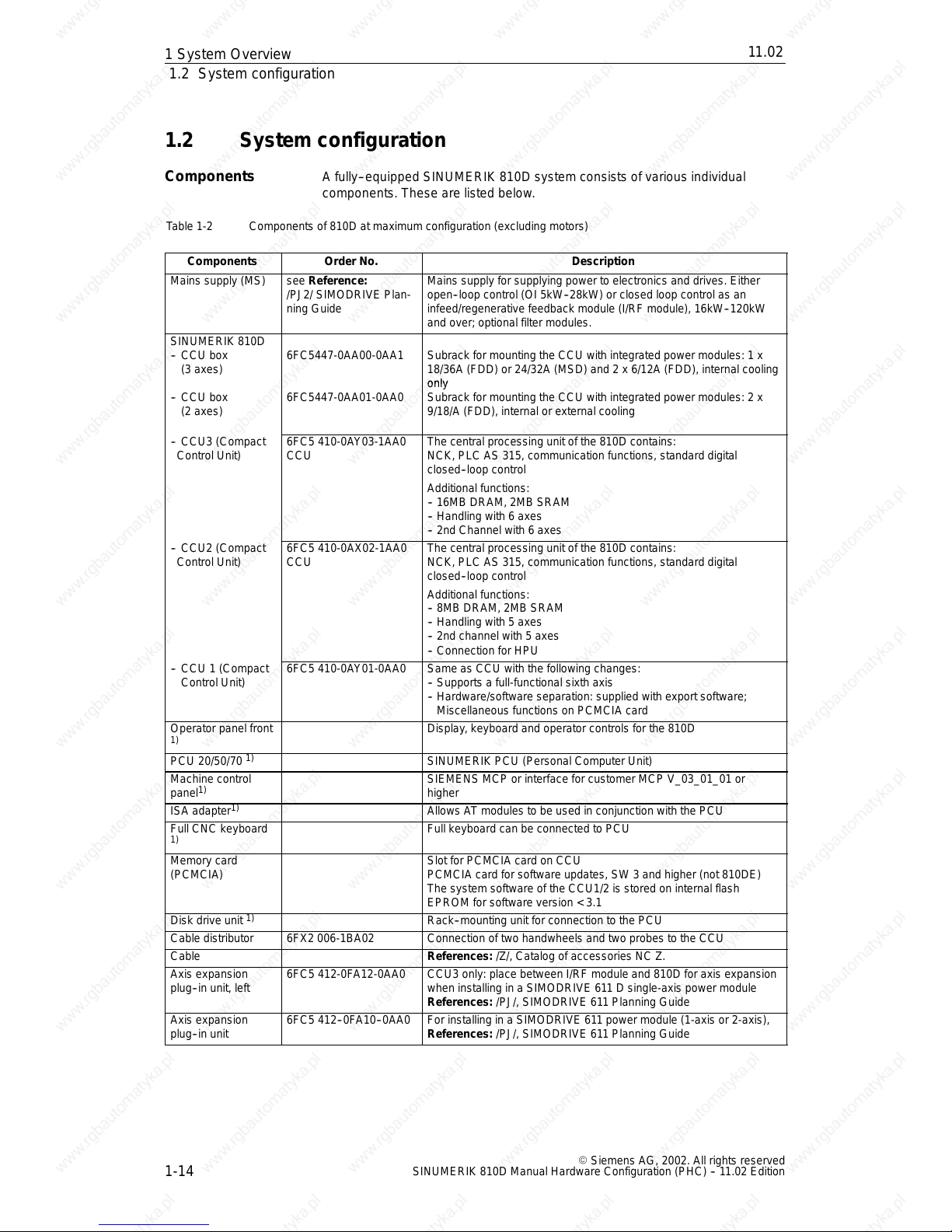
1.2 System configuration
A fully-- equipped SINUMERIK 810D system consistsof various individual
components. These are listedbelow.
Table 1-2 Components of 810D at maximum configuration (excluding motors)
Components Order No. Description
Mains supply (MS) see Reference:
/PJ2/ SIMODRIVE Plan-
ning Guide
Mains supply for supplying power to electronics and drives. Either
open--loop control (OI 5kW--28kW) or closed loop control as an
infeed/regenerative feedback module (I/RF module), 16kW--120kW
and over; optional filter modules.
SINUMERIK 810D
-- CCU box
(3 axes)
6FC5447-0AA00-0AA1 Subrack for mounting the CCU with integrated power modules: 1 x
18/36A (FDD) or 24/32A (MSD) and 2 x 6/12A (FDD), internal cooling
-- CCU box
(2 axes)
6FC5447-0AA01-0AA0
only
Subrack for mounting the CCU with integrated power modules: 2 x
9/18/A (FDD), internal or external cooling
-- CCU3 (Compact
Control Unit)
6FC5 410-0AY03-1AA0
CCU
The central processing unit of the 810D contains:
NCK, PLC AS 315, communication functions, standard digital
closed--loop control
Additional functions:
-- 16MB DRAM, 2MB SRAM
-- Handling with 6 axes
-- 2nd Channel with 6 axes
-- CCU2 (Compact
Control Unit)
6FC5 410-0AX02-1AA0
CCU
The central processing unit of the 810D contains:
NCK, PLC AS 315, communication functions, standard digital
closed--loop control
Additional functions:
-- 8MBDRAM, 2MB SRAM
-- Handling with 5 axes
-- 2nd channel with 5 axes
-- Connection for HPU
-- CCU 1 (Compact
Control Unit)
6FC5 410-0AY01-0AA0 Same as CCU with the following changes:
-- Supports a full-functional sixth axis
-- Hardware/software separation: supplied with export software;
Miscellaneous functions on PCMCIA card
Operator panel front
1)
Display, keyboard and operator controls for the 810D
PCU 20/50/70
1)
SINUMERIK PCU (Personal Computer Unit)
Machine control
panel
1)
SIEMENS MCP or interface for customer MCP V_03_01_01 or
higher
ISA adapter
1)
Allows AT modules to be used in conjunction with the PCU
Full CNC keyboard
1)
Full keyboard can be connected to PCU
Memory card
(PCMCIA)
Slot for PCMCIA card on CCU
PCMCIA card for software updates, SW 3 and higher (not 810DE)
The system software of the CCU1/2 is stored on internalflash
EPROM for software version < 3.1
Disk drive unit
1)
Rack--mounting unit for connection to the PCU
Cable distributor 6FX2 006-1BA02 Connection of two handwheels and two probes to the CCU
Cable References: /Z/, Catalog of accessories NC Z.
Axis expansion
plug--in unit, left
6FC5 412-0FA12-0AA0 CCU3 only: place between I/RF module and 810D for axis expansion
when installing in a SIMODRIVE 611 D single-axis power module
References: /PJ/, SIMODRIVE 611 Planning Guide
Axis expansion
plug--in unit
6FC5 412--0FA10--0AA0 For installing in a SIMODRIVE 611 power module (1-axis or 2-axis),
References: /PJ/, SIMODRIVE 611 Planning Guide
Components
1S
y
s
tem Overview
11.02
12.95
1.2 System configuration
1-15
E Siemens AG, 2002. All rights reserved
SINUMERIK 810D Manual Hardware Configuration (PHC) -- 11.02 Edition
Components DescriptionOrder No.
SIMATIC
components
References: /S7H/, Manual
Single I/O module
(EFP)
6FC5 411-0AA00-0AA0 PLC I/O module with 64 inputs and 32 short-circuit-proof outputs
NCU terminal
block
1)
6FC5 211-0AA00-0AA0 High-speed digital and analog NC I/Os on the SINUMERIK 810D
drive bus
Handheld unit
(HHU)
1)
6FX2 007-1AC.. Handheld unit with
handwheel, Emergency Stop button, keyswitch, override, enabling
switches, display, user-assignable keys,
connection via MPI bus and cable distributor
Handheld Terminal
(HT 6)
1)
6FC5 403-0AA10-0AA0 Handheld device combining the functions of the operator panel front
and MCP with
-- D i s pl a y,
-- Keyboard, enable key, Emergency Stop and Override button
-- RS-232 interface for archiving programs and data
-- Connection via cable and distributor to SINUMERIK 810D/840Di/
840D and FM357-2H
Distributor box
1)
6FX2 006-1BC00 For connection of the handheld unit to the MPI bus Connection for
Emergency Stop circuit, enabling, handwheel, 24VDC
Mini handheld unit
1)
6FX2 006-1BG00 Small handheld unit for setting up and operating simple machines in
the JobShop sector or similar applications.
Can be used with 810D, 840C, 840D and FM-NC.
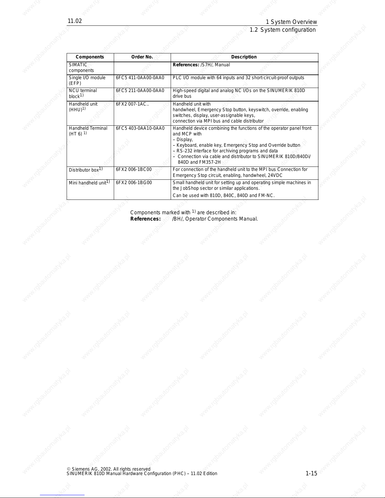
Components marked with1)are described in:
References: /BH/, OperatorComponents Manual.
1S
y
s
tem Overview
11.02
12.95
1.2 System configuration
1-16
E Siemens AG, 2002. All rights reserved
SINUMERIK 810D Manual Hardware Configuration (PHC) -- 11.02 Edition
MCP
Disk drive
unit
Operator panel front
Axis
expansion
plug
-in
unit
I/RF
FDD FDD
Handwheel (2x)
Measuring (2x) *)
Cable
distributor
Single
I/O module
810D
2x
Motor encoder
cable
Terminalblock
Motors
e.g. 1FNx, 1FEx, 1FKx
Distributor box
Motor cable
QWERTY
keyboard
5x
OI
or
2x
1x
PCU
MPI
cable
SIMATIC
IM cable
611
power
module
Encoder lead
direct
measuring system
Direct measuring
(e.g. at X416)
SIMATIC
PROFIBUS I/Os
Handheld
unit
HHU or miniHHU or HT 6
14
15
14
*) One measuring output can be replaced by a 3rd handwheel
HT 6
16
17
(CCU3)
Axis
expansion
plug
-in
unit
1x
MSD
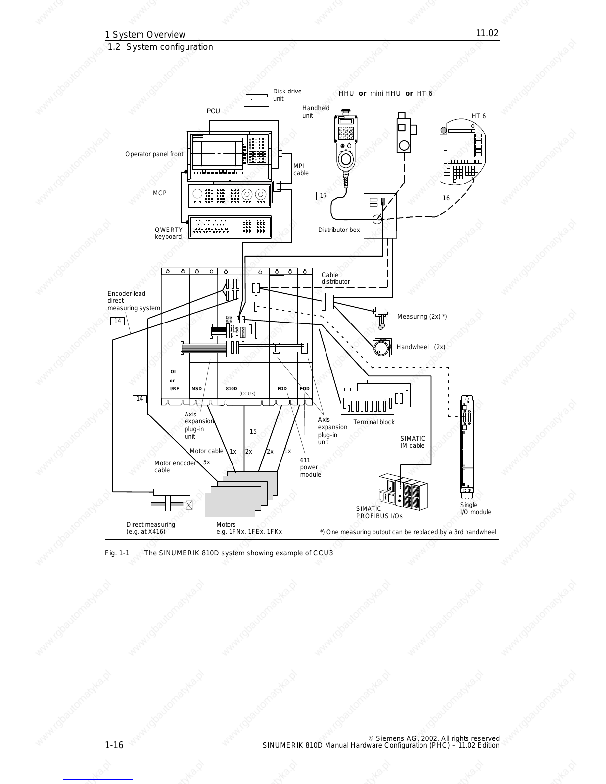
Fig. 1-1 The SINUMERIK 810D system showing example ofCCU3
1S
y
s
tem Overview
11.02
12.95
1.2 System configuration
1-17
E Siemens AG, 2002. All rights reserved
SINUMERIK 810D Manual Hardware Configuration (PHC) -- 11.02 Edition
17
X3
Floppy/interface
MCP
PG740 programming device
Cable distributor
QWERTY
MPI bus cable
MPI cable
X20
(rear view)
Distributor box
HHU
HHU handwheel
X4
X1
X2
X5
CCU 3
MPI bus cable
2
3
4
1
5
6
Handwheel
Probe
Shield
or
HT 6
16
PCU50
(right side of
housing)
PC card
Port on the left side of the housing
PS/2 mouse
COM1/RS--232/PLC
LPT1/PRINTER
VGA
24V power supply
USB
COM2
Ethernet
PCI slot PCI/ISA slot
MPI/DP
2
- -X307
- -X122
- -X102
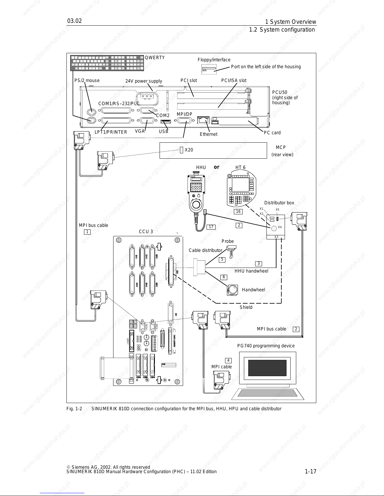
Fig. 1-2 SINUMERIK 810D connection configuration for the MPI bus, HHU, HPU and cable distributor
1S
y
s
tem Overview
03.02
12.95
1.2 System configuration
1-18
E Siemens AG, 2002. All rights reserved
SINUMERIK 810D Manual Hardware Configuration (PHC) -- 11.02 Edition
CCU3
IM
SIMATIC S7--300 I/Os
PS SMs
X2
SIMATIC S7-300 IM interconnecting cable
Shielded interconnecting cables
Single I/O module
Terminal block
Drive bus cable
Do not exceed maximum configuration !!
1)
1)
Terminator
Single I/O module Single I/O module
--X307
--X130
8
8
8
7 9
-- X 4 11
--X412
--X413--X416
--X415
--X414
--X121
--X111
--X122
--X102
--X431
Memory card
- -X306
- -X305 --X304
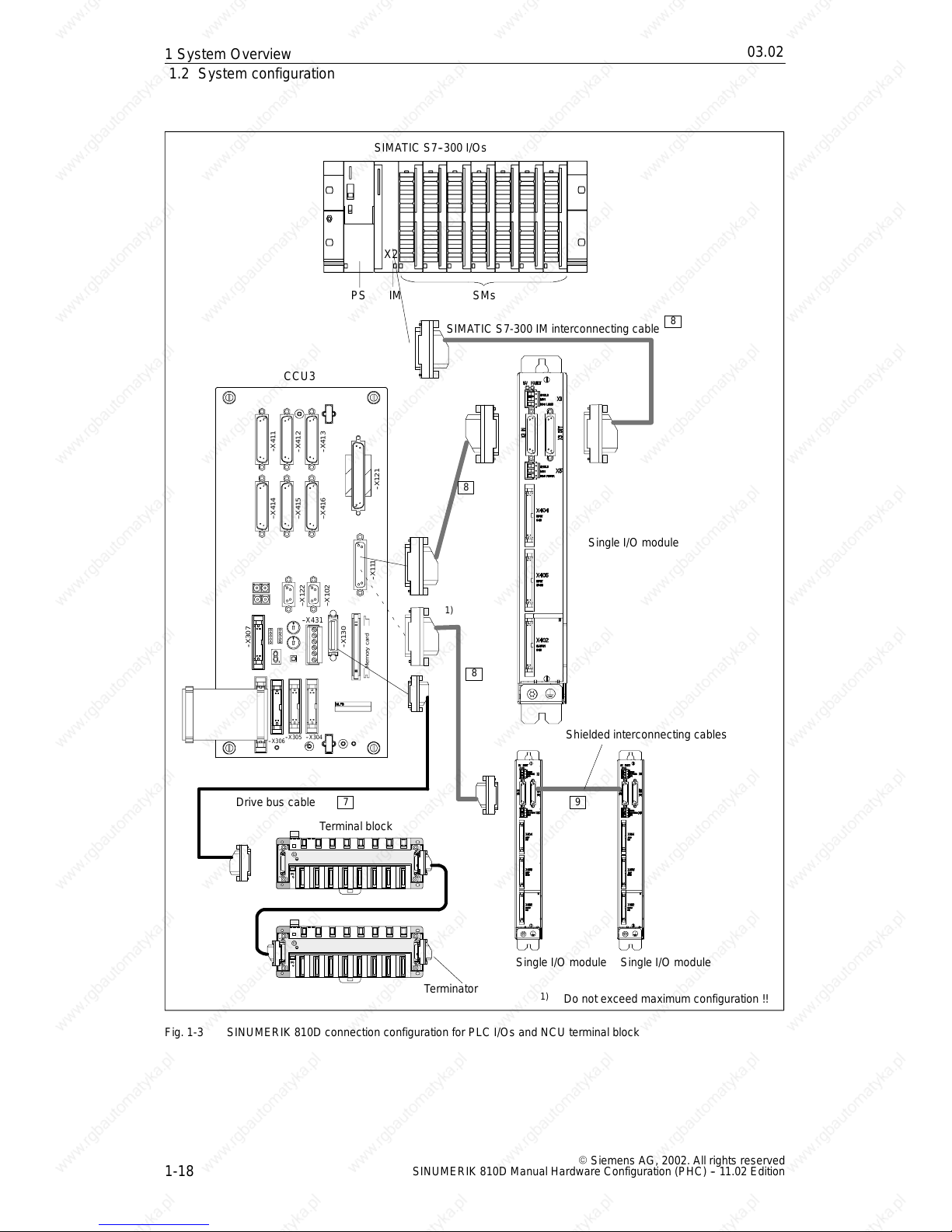
Fig. 1-3 SINUMERIK 810D connection configuration for PLC I/Os and NCU terminal block
1S
y
s
tem Overview
04.0003.02
12.95
1.2 System configuration
1-19
E Siemens AG, 2002. All rights reserved
SINUMERIK 810D Manual Hardware Configuration (PHC) -- 11.02 Edition
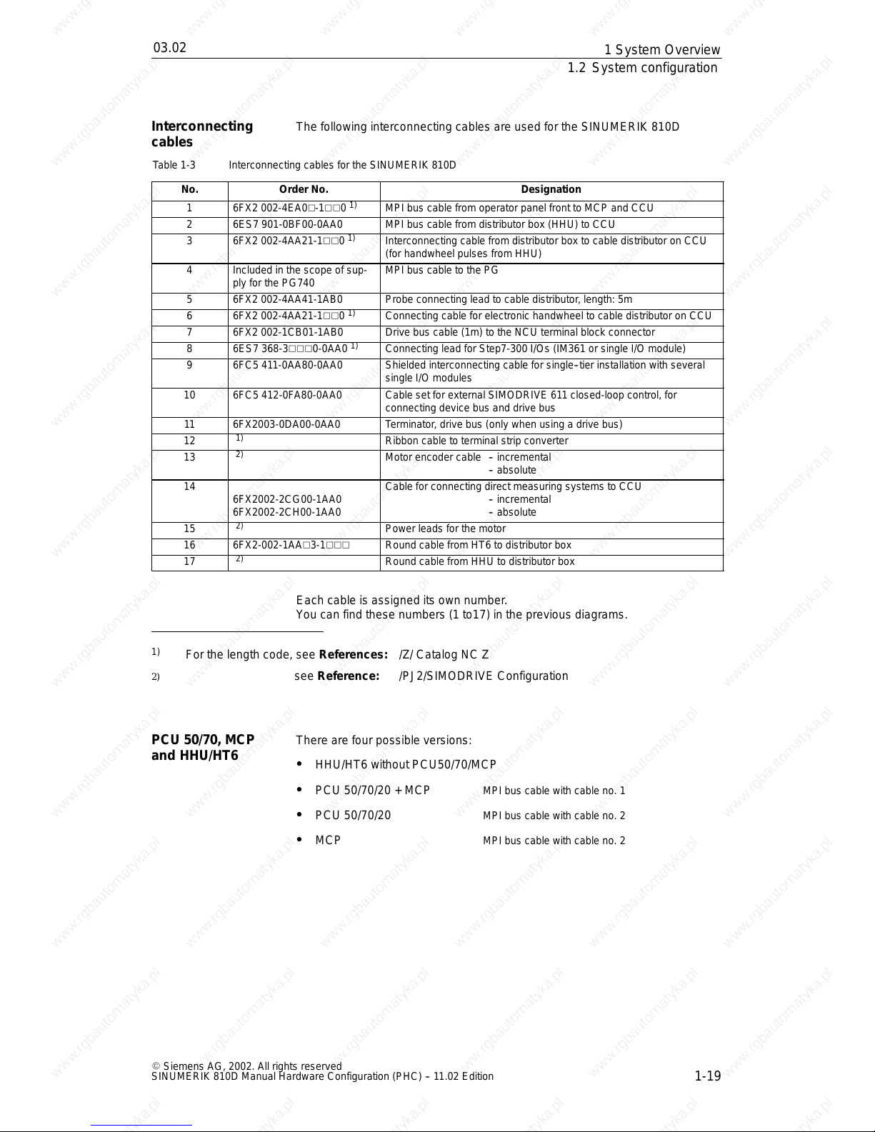
The following interconnecting cables are used for the SINUMERIK 810D
Table 1-3 Interconnecting cables for the SINUMERIK 810D
No.
Order No. Designation
1 6FX2 002-4EA0V-1VV0
1)
MPI bus cable from operator panel front to MCP and CCU
2 6ES7 901-0BF00-0AA0 MPI bus cable from distributorbox (HHU) to CCU
3 6FX2 002-4AA21-1VV0
1)
Interconnecting cable from distributor box to cable distributor on CCU
(for handwheel pulses from HHU)
4 Included in the scope of sup-
ply for the PG740
MPI bus cable to the PG
5 6FX2 002-4AA41-1AB0 Probe connecting lead to cable distributor,length: 5m
6 6FX2 002-4AA21-1VV0
1)
Connecting cable for electronic handwheel to cable distributor on CCU
7 6FX2 002-1CB01-1AB0 Drive bus cable (1m) to the NCU terminal block connector
8 6ES7 368-3VVV0-0AA0
1)
Connecting lead for Step7-300 I/Os (IM361 or single I/O module)
9 6FC5 411-0AA80-0AA0 Shielded interconnecting cable for single--tier installation with several
single I/O modules
10 6FC5 412-0FA80-0AA0 Cable set for external SIMODRIVE 611 closed-loop control, for
connecting device bus and drive bus
11 6FX2003-0DA00-0AA0 Terminator ,drive bus (only when using a drive bus)
12
1)
Ribbon cable to terminal strip converter
13
2)
Motor encoder cable -- incremental
-- absolute
14
6FX2002-2CG00-1AA0
6FX2002-2CH00-1AA0
Cable for connecting direct measuring systems to CCU
-- incremental
-- absolute
15
2)
Power leads for the motor
16 6FX2-002-1AAV3-1VVV Round cable from HT6 to distributor box
17
2)
Round cable from HHU to distributor box
Each cable is assigned its own number.
You can find these numbers (1to17) in the previousdiagrams.
1)
For the length code, see References: /Z/ Catalog NC Z
2) see Reference: /PJ2/SIMODRIVEConfiguration
There are four possibleversions:
S HHU/HT6 without PCU50/70/MCP
S PCU 50/70/20 + MCP MPI bus cable with cable no. 1
S PCU 50/70/20 MPI bus cable with cable no. 2
S MCP MPI bus cable with cable no. 2
Interconnecting
cables
PCU 50/70, MCP
and HHU/HT6
1S
y
s
tem Overview
03.02
12.95
1.2 System configuration
1-20
E Siemens AG, 2002. All rights reserved
SINUMERIK 810D Manual Hardware Configuration (PHC) -- 11.02 Edition
The number of axes on the SINUMERIK 810D can be expanded:
S to five axes including spindle with CCU2 and CCU1 (< SW 3.1)
S to six axes including spindle with CCU1 (SW 3.1 and higher)and CCU3 (a
closed
-loop control card is required for the 6th axis with CCU1)
There are two ways of doing this:
either an axis expansion plug
-in unit and a SIMODRIVE 611 power
module connected at the axis expansion terminal
or SIMODRIVE 611Dclosed
-loop control module with SIMODRIVE611
power module connected to the drive bus/device bus
Axis expansion plug --in units arealways used when no more than six measu-
ring channels are required for the SINUMERIK 810D. The unit is plugged intoa
SIMODRIVE 611power module. Axis expansion plug
-in units are designed for
1
-axis and 2-axis power modules. The plug--in unitis supplied complete with
ribbon cables.
If six SINUMERIK 810D measuring channels are not enough, SIMODRIVE 611
closed
-loop control modules must be installed in the SIMODRIVE611 power
modules to connect furthermeasuring systems (connectionvia drive bus with
drive bus terminator).When using 611D closed
-loop control modules, it may be
necessary to connect the NCU terminal block to the free drive bus connector on
the 611D closed
-loop control.
See Chapter 5, Axis Expansion
CCU1/2:
1
-axis or 2-axis power modules can be used foraxis expansion. 2-axis power
modules can be used for axes and spindles.Power modules must always be
installedon the rightof the SINUMERIK 810D.
CCU3:
The new CCU3 can controlup to 6 axes “onboard”. A new left expansion plug
-in
unit is available in addition to the existing axis expansion units.
All power sections af the 611Dseries can be connected for axis expansion as
external power modules.
With SW 3.1 or lower, it is not possible to combinethe two types of axis expan-
sion. The numberof drives is limited to 5 for CCU1/2.
With SW 6.3 and higher,the limitation for CCU3 is six drives.
Many differentdrive combinations can be used to implement expansion levels
1-- 6. If the spindles are to be operated on the internal power module, thismust
be connected to the 24A/32A power section (A1).
Axis expansion on
the 810D
Axis expansion
plug
-in unit
Axis expansion
closed
-loop
control
module
Power modules
Combinations
1S
y
s
tem Overview
11.02
12.95
1.2 System configuration
1-21
E Siemens AG, 2002. All rights reserved
SINUMERIK 810D Manual Hardware Configuration (PHC) -- 11.02 Edition
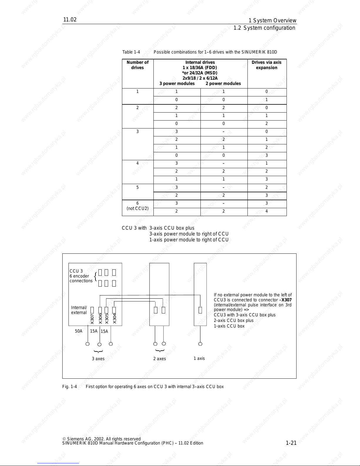
Table 1-4 Possible combinations for 1--6 drives with the SINUMERIK 810D
Number of
drives
Internal drives
1 x 18/36A (FDD)
*or 24/32A (MSD)
2x9/18 / 2 x 6/12A
3 power modules 2power modules
Drives via axis
expansion
1 1 1 0
0 0 1
2 2 2 0
1 1 1
0 0 2
3 3 -- 0
2 2 1
1 1 2
0 0 3
4 3 -- 1
2 2 2
1 1 3
5 3 -- 2
2 2 3
6
3 -- 3
(not CCU2)
2 2 4
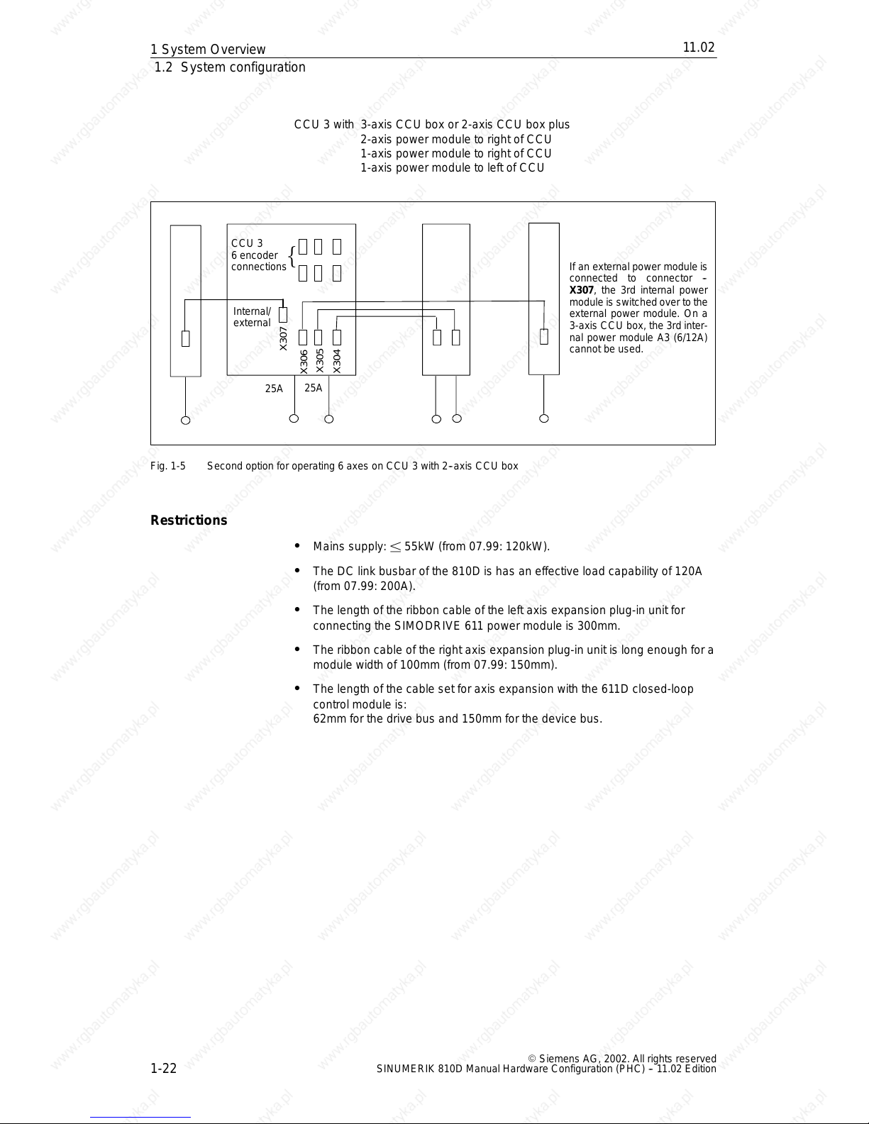
CCU 3 with 3-axis CCU box plus
3-axis power module to right of CCU
1-axis power module to right of CCU
CCU 3
6 encoder
connections
Internal/
external
X307
50A 15A
15A
3 axes 2 axes
1axis
≡
≡
≡
If no external power module to the left of
CCU3 is connected to connector --X307
(internal/external pulse interface on 3rd
power module) =>
CCU3 with 3
-axis CCU box plus
2
-axis CCU box plus
1
-axis CCU box
X306
X305
X304
Fig. 1-4 First option for operating 6 axes on CCU 3 with internal 3--axis CCU box
1S
y
s
tem Overview
11.02
12.95
1.2 System configuration
1-22
E Siemens AG, 2002. All rights reserved
SINUMERIK 810D Manual Hardware Configuration (PHC) -- 11.02 Edition
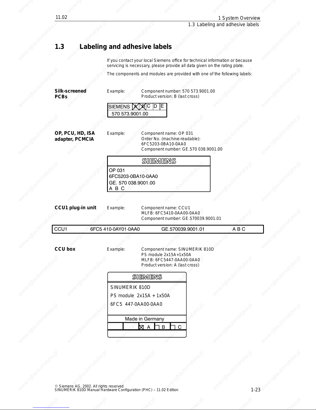
CCU 3 with 3-axis CCU box or 2-axis CCU box plus
2-axis power module to right of CCU
1-axis power module to right of CCU
1-axis power module to left of CCU
CCU 3
6 encoder
connections
Internal/
external
X304
25A
25A
≡
If an external power module is
connected to connector --
X307, the 3rd internal power
module is switchedover to the
external power module. On a
3-axis CCU box, the 3rd inter-
nal power module A3 (6/12A)
cannot be used.
X305
X306
X307
Fig. 1-5 Second option for operating 6 axes on CCU 3 with 2--axis CCU box
S Mains supply: ± 55kW (from 07.99: 120kW).
S The DC link busbar of the 810D is has an effective load capability of 120A
(from07.99: 200A).
S The length of the ribbon cable of the left axis expansion plug-inunit for
connecting the SIMODRIVE 611 power module is 300mm.
S The ribbon cable of the right axis expansion plug-in unit is long enough for a
module width of 100mm (from07.99: 150mm).
S The length of the cable set foraxis expansion with the 611D closed-loop
controlmodule is:
62mm for the drivebus and 150mm for the device bus.
Restrictions
1S
y
s
tem Overview
11.02
12.95
1.3 Labeling and adhesive labels
1-23
E Siemens AG, 2002. All rights reserved
SINUMERIK 810D Manual Hardware Configuration (PHC) -- 11.02 Edition
1.3 Labeling and adhesive labels
If you contact your local Siemens office for technical informationor because
servicing is necessary,please provide all data given on the rating plate.
The components and modules are providedwith one of the following labels:
Example: Component number: 570 573.9001.00
Product version: B (last cross)
570 573.9001.00
E
D
C
SIEMENS
A
B
Example: Component name: OP 031
Order No. (machine-readable):
6FC5203-0BA10-0AA0
Component number: GE.570 038.9001.00
GE. 570 038.9001.00
OP 031
6FC5203-0BA10-0AA0
CBA
Example: Component name: CCU1
MLFB: 6FC5410-0AA00-0AA0
Component number: GE.570039.9001.01
ABCGE.570039.9001.016FC5 410-0AY01-0AA0CCU1
Example: Component name: SINUMERIK 810D
PS module 2x15A+1x50A
MLFB: 6FC5447-0AA00-0AA0
Product version: A (last cross)
SINUMERIK 810D
PS module 2x15A + 1x50A
6FC5 447
-0AA00-0AA0
CBA
Made in Germany
Silk-screened
PCBs
OP, PCU, HD, ISA
adapter, PCMCIA
CCU1 plug
-in unit
CCU box
1S
y
s
tem Overview
11.02
12.95
1.3 Labeling and adhesive labels
1-24
E Siemens AG, 2002. All rights reserved
SINUMERIK 810D Manual Hardware Configuration (PHC) -- 11.02 Edition
Warning
The modules containelectrostatic sensitive components. Before touching an
electronicmodule,the persons carrying out the work must themselves be
electrostatically discharged. The simplest way of doing this is to touch an
electrically conducting earthed object(e.g.a bare metal part of a switchboard
or a plug socket protective conductor).
J
ESD symbol
1S
y
s
tem Overview
2-25
E Siemens AG, 2002. All rights reserved
SINUMERIK 810D Manual Hardware Configuration (PHC) -- 11.02 Edition
Installation Conditions
2.1 Secondary electrical conditions
The control is testedfor compliance with the ambient conditions specified
below.Trouble-free operation is guaranteed only if:
S these ambient conditions are maintained in operation and transportation.
S originalcomponents and spare parts are used. This applies in particular to
the use of specified cables and plug connectors.
S mounting is carried out properly.
The control must notbe started up untilit has been confirmedthatit complies
with the provisions of the 98/37/EC Directive.
Reference: /EMV/, EMC Installation Guideline
The installation conditions must be complied with forthe complete system.
Please contact your localSiemens officeor representativefor assistance and
advice.
Compliance with
the connection
conditions
Additional
information
Assistance and
advice
2
12.95
2.1 Secondary electrical conditions
2-26
E Siemens AG, 2002. All rights reserved
SINUMERIK 810D Manual Hardware Configuration (PHC) -- 11.02 Edition
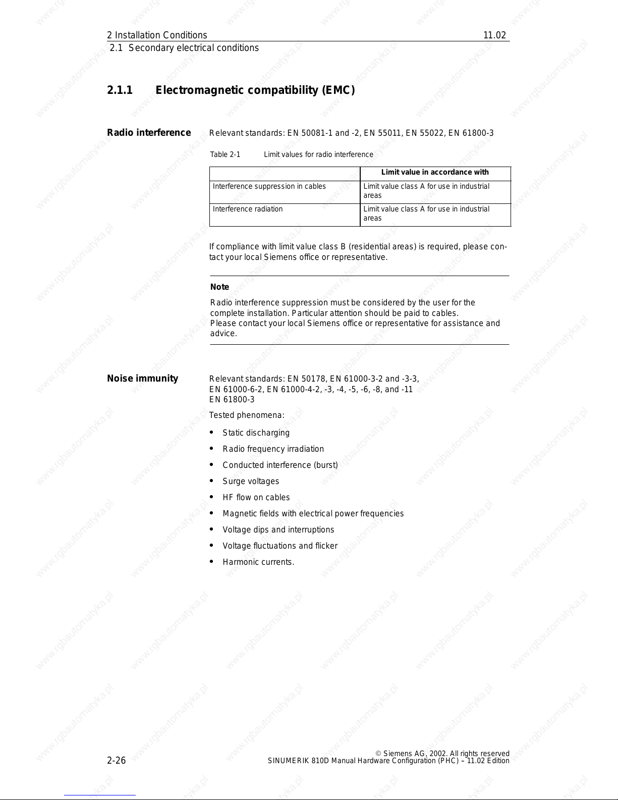
2.1.1 Electromagnetic compatibility (EMC)
Relevant standards: EN 50081-1 and -2, EN 55011, EN 55022,EN 61800-3
Table 2-1 Limit values for radio interference
Limit value in accordance with
Interference suppression in cables Limitvalue class A for use in industrial
areas
Interference radiation Limit value class A for use in industrial
areas
If compliance with limit value class B (residentialareas) is required,please con-
tact your local Siemens office or representative.
Note
Radio interferencesuppression must be consideredby the userfor the
complete installation. Particular attentionshould be paid to cables.
Please contact your localSiemens officeor representativefor assistance and
advice.
Relevant standards: EN 50178, EN 61000-3-2 and -3-3,
EN 61000-6-2, EN 61000-4-2,-3,-4, -5, -6, -8, and -11
EN 61800-3
Tested phenomena:
S Static discharging
S Radio frequency irradiation
S Conducted interference(burst)
S Surge voltages
S HF flow on cables
S Magnetic fields with electrical power frequencies
S Voltage dips and interruptions
S Voltage fluctuations and flicker
S Harmonic currents.
Radio interference
Noise immunity
2In
stall
a
tion Condition
s
11.02
12.95
2.1 Secondary electrical conditions
2-27
E Siemens AG, 2002. All rights reserved
SINUMERIK 810D Manual Hardware Configuration (PHC) -- 11.02 Edition
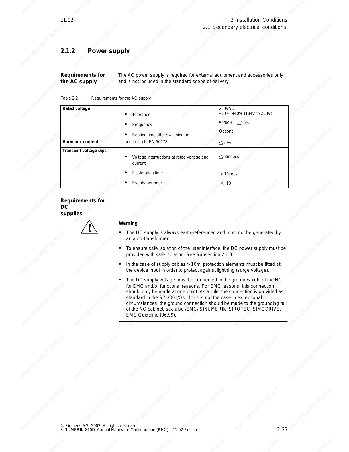
2.1.2 Power supply
The AC power supply is required for external equipment and accessories only
and is not included in the standardscope of delivery.
Table 2-2 Requirements for the AC supply
Rated voltage
S Tolerance
S Frequency
S Booting time after switching on
230VAC
--20%, +10% (184V to 253V)
50/60Hz ¦10%
Optional
Harmonic content according to EN 50178
±10%
Transient voltage dips
S Voltage interruptions at rated voltage and
current
S Restoration time
S Events per hour
± 3msecs
² 10secs
± 10
!
Warning
S The DC supply is always earth-referenced and must not be generated by
an auto-transformer.
S To ensure safeisolationof the user interface, the DC power supply must be
provided with safe isolation. See Subsection2.1.3.
S In the case of supply cables > 10m, protection elements must be fittedat
the device input in order to protect against lightning (surge voltage).
S The DC supply voltage must be connected to the ground/shield of the NC
for EMC and/or functional reasons. For EMC reasons, this connection
should only be made at one point. As a rule, the connection is provided as
standard in the S7-300 I/Os.If this is not the case in exceptional
circumstances,the ground connection should be made to the grounding rail
of the NC cabinet; see also /EMC/ SINUMERIK, SIROTEC, SIMODRIVE,
EMC Guideline (06.99).
Requirements for
the AC supply
Requirements for
DC
supplies
2In
stall
a
tion Condition
s
11.02
12.95
2.1 Secondary electrical conditions
2-28
E Siemens AG, 2002. All rights reserved
SINUMERIK 810D Manual Hardware Configuration (PHC) -- 11.02 Edition
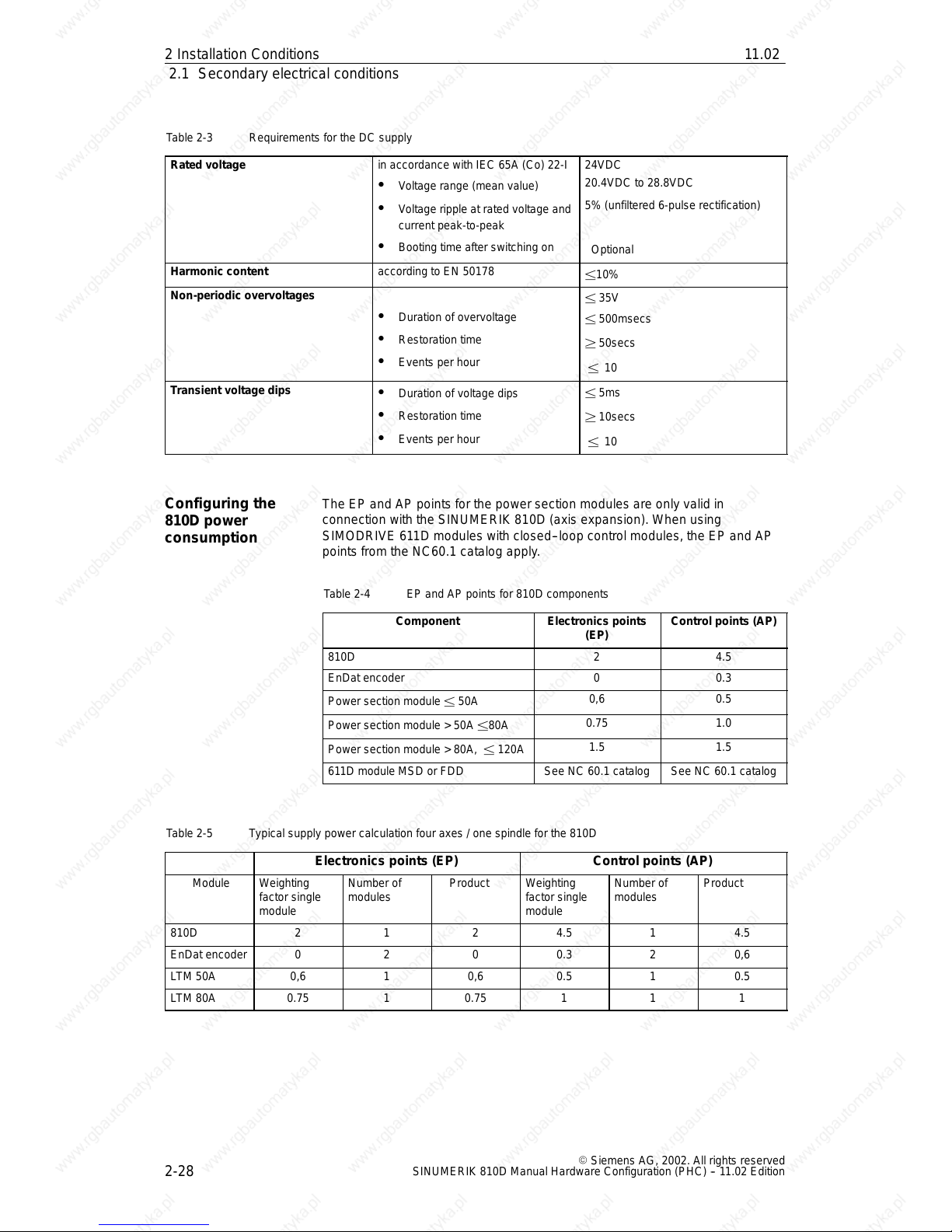
Table 2-3 Requirements for the DC supply
Rated voltage
in accordance with IEC 65A (Co) 22-I
S Voltage range (mean value)
S Voltage ripple at rated voltage and
current peak-to-peak
S Booting time after switching on
24VDC
20.4VDC to 28.8VDC
5% (unfiltered 6-pulse rectification)
Optional
Harmonic content according to EN 50178
±10%
Non-periodic overvoltages
S Duration of overvoltage
S Restoration time
S Events per hour
± 35V
± 500msecs
² 50secs
± 10
Transient voltage dips
S Duration of voltage dips
S Restoration time
S Events per hour
± 5ms
² 10secs
± 10
The EP and AP pointsfor the power section modules are only validin
connection with the SINUMERIK 810D (axis expansion). When using
SIMODRIVE 611Dmodules with closed--loop control modules, the EP and AP
points from the NC60.1 catalog apply.
Table 2-4 EP and AP points for 810D components
Component
Electronics points
(EP)
Control points (AP)
810D 2 4.5
EnDat encoder 0 0.3
Power section module ± 50A
0,6 0.5
Power section module > 50A ±80A
0.75 1.0
Power section module > 80A, ± 120A
1.5 1.5
611D module MSD or FDD See NC 60.1 catalog See NC 60.1 catalog
Table 2-5 Typical supply power calculation four axes / one spindle for the 810D
Electronicspoints (EP) Control points (AP)
Module Weighting
factor single
module
Number of
modules
Product Weighting
factor single
module
Number of
modules
Product
810D
2
1 2 4.5 1 4.5
EnDat encoder 0 2 0 0.3 2 0,6
LTM 50A 0,6 1 0,6 0.5 1 0.5
LTM 80A 0.75 1 0.75 1 1 1
Configuring the
810D power
consumption
2In
stall
a
tion Condition
s
11.02
 Loading...