

SINUMERIK
SINUMERIK 808D ADVANCED
Programming and Operating Manual (Turning)
User Manual
Legal information
Warning notice system
DANGER
will
WARNING
may
CAUTION
NOTICE
Qualified Personnel
personnel qualified
Proper use of Siemens products
WARNING
This manual contains notices you have to observe in order to ensure your personal safety, as well as to prevent damage to property. The
notices referring to your personal safety are highlighted in the manual by a safety alert symbol, notices referring only to property damage
have no safety alert symbol. These notices shown below are graded according to the degree of danger.
indicates that death or severe personal injury
indicates that death or severe personal injury
indicates that minor personal injury can result if proper precautions are not taken.
indicates that property damage can result if proper precautions are not taken.
If more than one degree of danger is present, the warning notice representing the highest degree of danger will be used. A notice warning of
injury to persons with a safety alert symbol may also include a warning relating to property damage.
The product/system described in this documentation may be operated only by
the relevant documentation, in particular its warning notices and safety instructions. Qualified personnel are those who, based on their
training and experience, are capable of identifying risks and avoiding potential hazards when working with these products/systems.
Note the following:
Siemens products may only be used for the applications described in the catalog and in the relevant technical documentation. If products
and components from other manufacturers are used, these must be recommended or approved by Siemens. Proper transport, storage,
installation, assembly, commissioning, operation and maintenance are required to ensure that the products operate safely and without any
problems. The permissible ambient conditions must be complied with. The information in the relevant documentation must be observed.
result if proper precautions are not taken.
result if proper precautions are not taken.
for the specific task in accordance with
© Siemens AG 2015. All rights reserved
6FC5398-5DP10-0BA2, 06/2015
1
Preface
Applicable software versions for turning
Applicable products
Control system
Software version
Preface
Documentation components and target groups
Document
Recommended target group
My Documentation Manager (MDM)
Standard scope
Technical support
Country
Hotline
Further service contact information:
http://www.siemens.com.cn/808D
EC Declaration of Conformity
67385845
This manual is applicable to the following control system:
SINUMERIK 808D ADVANCED T (Turning) V4.7
Programming and Operating Manual (Turning) Programmers and operators of turning machines
Programming and Operating Manual (Milling) Programmers and operators of milling machines
Diagnostics Manual Mechanical and electrical designers, commissioning engi-
neers, machine operators, and service and maintenance
personnel
Under the following link you will find information to individually compile your documentation based on the Siemens content:
www.siemens.com/mdm
This manual only describes the functionality of the standard version. Extensions or changes made by the machine tool
manufacturer are documented by the machine tool manufacturer.
Germany +49 911 895 7222
China +86 400 810 4288
1)
You can find more hotline information at the global Web site given above.
The EC Declaration of Conformity for the EMC Directive can be found on the Internet at:
http://www.siemens.com/automation/service&support.
Here, enter the number
Programming and Operating Manual (Turning)
2 6FC5398-5DP10-0BA2, 06/2015
1)
• Global Web site:
https://support.industry.siemens.com/sc/us/en/sc/list-of-countries/oid2044
• Chinese Web site:
as the search term or contact your local Siemens office.

Table of contents
Preface ................................................................................................................................................................... 2
1 Fundamental safety instructions .............................................................................................................................. 7
2 Introduction............................................................................................................................................................. 8
3 Turning on, reference point approach .................................................................................................................... 15
4 Setting-up ............................................................................................................................................................. 16
5 Part programming ................................................................................................................................................. 30
6 Automatic machining ............................................................................................................................................. 36
7 Data backup ......................................................................................................................................................... 49
1.1 General safety instructions ...................................................................................................................... 7
1.2 Industrial security .................................................................................................................................... 7
2.1 CNC operator panels ............................................................................................................................... 8
2.1.1 Panel Processing Unit (PPU) versions .................................................................................................... 8
2.1.2 Control elements on the PPU161.3 ......................................................................................................... 8
2.2 Machine control panels .......................................................................................................................... 10
2.2.1 Machine Control Panel (MCP) versions ................................................................................................. 10
2.2.2 Control elements on the MCP ............................................................................................................... 10
2.3 Screen layout ........................................................................................................................................ 12
2.4 Protection levels .................................................................................................................................... 13
2.5 Setting user interface language ............................................................................................................. 14
4.1 Coordinate systems ............................................................................................................................... 16
4.2 Setting up tools ...................................................................................................................................... 18
4.2.1 Creating a new tool................................................................................................................................ 18
4.2.2 Activating the tool .................................................................................................................................. 20
4.2.3 Assigning the handwheel ....................................................................................................................... 21
4.2.4 Activating the spindle............................................................................................................................. 22
4.2.5 Measuring the tool (manually) ............................................................................................................... 23
4.2.6 Verifying the tool offset result in "MDA" mode ....................................................................................... 27
4.2.7 Entering/modifying the tool wear data ................................................................................................... 28
4.3 Operating area overview ....................................................................................................................... 29
5.1 Creating a part program ........................................................................................................................ 31
5.2 Editing part programs ............................................................................................................................ 31
5.3 Managing part programs ....................................................................................................................... 33
6.1 Simulating machining ............................................................................................................................ 37
6.1.1 Simulation prior to machining of the workpiece ..................................................................................... 37
6.1.2 Simultaneous recording prior to machining of the workpiece ................................................................ 39
6.1.3 Simultaneous recording during machining of the workpiece .................................................................. 39
6.2 Program control ..................................................................................................................................... 40
6.3 Program test .......................................................................................................................................... 41
6.4 Starting and stopping/interrupting a part program ................................................................................. 43
6.5 Executing/transferring a part program through the Ethernet connection ............................................... 44
6.5.1 Configuring the network drive ................................................................................................................ 44
6.5.2 Executing from external (through Ethernet connection)......................................................................... 46
6.5.3 Transferring from external (through Ethernet connection) ..................................................................... 47
6.6 Machining at a specific point ................................................................................................................. 48
7.1 Internal data backup .............................................................................................................................. 49
Programming and Operating Manual (Turning)
6FC5398-5DP10-0BA2, 06/2015
3

8 Programming principles .........................................................................................................................................53
7.2 External data backup ............................................................................................................................ 50
7.2.1 External data backup in a data archive ................................................................................................. 50
7.2.2 Exernal data backup of separate files ................................................................................................... 52
8.1 Fundamentals of programming ............................................................................................................. 53
8.1.1 Program names .................................................................................................................................... 53
8.1.2 Program structure ................................................................................................................................. 53
8.2 Positional data ...................................................................................................................................... 53
8.2.1 Programming dimensions ..................................................................................................................... 53
8.2.2 Absolute/incremental dimensioning: G90, G91, AC, IC ......................................................................... 54
8.2.3 Dimensions in metric units and inches: G71, G70, G710, G700 ........................................................... 55
8.2.4 Radius/diameter dimensions: DIAMOF, DIAMON, DIAM90 .................................................................. 56
8.2.5 Programmable work offset: TRANS, ATRANS ...................................................................................... 56
8.2.6 Programmable scaling factor: SCALE, ASCALE ................................................................................... 59
8.2.7 Workpiece clamping - settable work offset: G54 to G59, G500, G53, G153 ......................................... 60
8.2.8 Kinematic transformation ...................................................................................................................... 61
8.2.8.1 Milling on turned parts (TRANSMIT) ..................................................................................................... 61
8.2.8.2 Cylinder surface transformation (TRACYL) ........................................................................................... 63
8.3 Linear interpolation................................................................................................................................ 69
8.3.1 Linear interpolation with rapid traverse: G0 ........................................................................................... 69
8.3.2 Feedrate F ............................................................................................................................................ 70
8.3.3 Linear interpolation with feedrate: G1 ................................................................................................... 71
8.4 Circular interpolation ............................................................................................................................. 71
8.4.1 Circular interpolation: G2, G3 ................................................................................................................ 71
8.4.2 Circular interpolation via intermediate point: CIP .................................................................................. 74
8.4.3 Circle with tangential transition: CT ....................................................................................................... 75
8.5 Thread cutting ....................................................................................................................................... 75
8.5.1 Thread cutting with constant lead: G33 ................................................................................................. 75
8.5.2 Programmable run-in and run-out path for G33: DITS, DITE ................................................................ 78
8.5.3 Thread cutting with variable lead: G34, G35 ......................................................................................... 79
8.5.4 Thread interpolation: G331, G332 ......................................................................................................... 80
8.6 Fixed point approach............................................................................................................................. 81
8.6.1 Fixed point approach: G75 .................................................................................................................... 81
8.6.2 Reference point approach: G74 ............................................................................................................ 81
8.7 Acceleration control and exact stop/continuous path ............................................................................ 82
8.7.1 Exact stop/continuous-path control mode: G9, G60, G64 ..................................................................... 82
8.7.2 Acceleration pattern: BRISK, SOFT ...................................................................................................... 84
8.7.3 Dwell Time: G4 ..................................................................................................................................... 84
8.8 The third axis ........................................................................................................................................ 85
8.9 Spindle movements............................................................................................................................... 85
Spindle speed S, directions of rotation .................................................................................................. 85
8.9.1
8
.9.2 Spindle positioning ................................................................................................................................ 86
8.9.2.1 Spindle positioning (SPOS, SPOSA, M19, M70, WAITS) ..................................................................... 86
8.9.2.2 Spindle positioning (SPOS, SPOSA, M19, M70, WAITS): Further information ..................................... 90
8.9.3 Gear stages .......................................................................................................................................... 92
8.10 Special turning functions ....................................................................................................................... 92
8.10.1 Constant cutting rate: G96, G97 ........................................................................................................... 92
8.10.2 Rounding, chamfer ................................................................................................................................ 93
8.10.3 Contour definition programming ............................................................................................................ 96
8.11 Tool and tool offset................................................................................................................................ 97
8.11.1 General information (turning) ................................................................................................................ 97
8.11.2 Tool T (turning) ..................................................................................................................................... 98
8.11.3 Tool offset number D (turning) .............................................................................................................. 98
8.11.4 Selecting the tool radius compensation: G41, G42 ............................................................................. 101
8.11.5 Corner behavior: G450, G451 ............................................................................................................. 103
8.11.6 Tool radius compensation OFF: G40 .................................................................................................. 103
8.11.7 Special cases of the tool radius compensation ................................................................................... 104
8.11.8 Example of tool radius compensation (turning) ................................................................................... 105
8.11.9 Special handling of tool compensation (turning) ................................................................................. 105
Programming and Operating Manual (Turning)
4 6FC5398-5DP10-0BA2, 06/2015

9 Cycles ................................................................................................................................................................ 119
10 Typical turning programs ..................................................................................................................................... 189
A Appendix ............................................................................................................................................................ 194
8.12 Miscellaneous function M .................................................................................................................... 106
8.13 H function ............................................................................................................................................ 107
8.14 Arithmetic parameters, LUD and PLC variables .................................................................................. 107
8.14.1 Arithmetic parameter R ........................................................................................................................ 107
8.14.2 Local User Data (LUD) ........................................................................................................................ 108
8.14.3 Reading and writing PLC variables ..................................................................................................... 109
8.15 Program jumps .................................................................................................................................... 110
8.15.1 Unconditional program jumps .............................................................................................................. 110
8.15.2 Conditional program jumps .................................................................................................................. 111
8.15.3 Program example for jumps ................................................................................................................ 112
8.15.4 Jump destination for program jumps ................................................................................................... 113
8.16 Subroutine technique........................................................................................................................... 113
8.16.1 General information ............................................................................................................................. 113
8.16.2 Calling machining cycles (turning) ....................................................................................................... 115
8.16.3 Executing external subroutines (EXTCALL) ........................................................................................ 115
8.17 Timers and workpiece counters ........................................................................................................... 116
8.17.1 Runtime timer ...................................................................................................................................... 116
8.17.2 Workpiece counter............................................................................................................................... 118
9.1 Overview of cycles............................................................................................................................... 119
9.2 Programming cycles ............................................................................................................................ 120
9.3 Graphical cycle support in the program editor ..................................................................................... 121
9.4 Drilling cycles ...................................................................................................................................... 122
9.4.1 General information ............................................................................................................................. 122
9.4.2 Requirements ...................................................................................................................................... 122
9.4.3 Drilling, centering - CYCLE81 .............................................................................................................. 125
9.4.4 Drilling, counterboring - CYCLE82....................................................................................................... 127
9.4.5 Deep-hole drilling - CYCLE83 ............................................................................................................. 129
9.4.6 Rigid tapping - CYCLE84 .................................................................................................................... 133
9.4.7 Tapping with compensating chuck - CYCLE840 ................................................................................. 137
9.4.8 Reaming1 - CYCLE85 ......................................................................................................................... 141
9.4.9 Boring - CYCLE86 ............................................................................................................................... 143
9.5 Turning cycles ..................................................................................................................................... 145
9.5.1 Requirements ...................................................................................................................................... 145
9.5.2 Cutoff - CYCLE92 ................................................................................................................................ 147
9.5.3 Groove - CYCLE93.............................................................................................................................. 149
9.5.4 Undercut (forms E and F to DIN) - CYCLE94 ...................................................................................... 156
9.5.5 Cutting with relief cut - CYCLE95 ........................................................................................................ 159
9.5.6 Thread undercut - CYCLE96 ............................................................................................................... 173
9.5.7 Thread chaining - CYCLE98 ................................................................................................................ 176
9.5.8 Thread cutting - CYCLE99 .................................................................................................................. 181
9.6 Error messages and error handling ..................................................................................................... 188
9.6.1 General Information ............................................................................................................................. 188
9.6.2 Error handling in the cycles ................................................................................................................. 188
9.6.3 Overview of cycle alarms ..................................................................................................................... 188
9.6.4 Messages in the cycles ....................................................................................................................... 188
A.1 Creating a new cutting edge ................................................................................................................ 194
A.2 Setting up the workpiece ..................................................................................................................... 195
A.2.1 Measuring the workpiece ..................................................................................................................... 195
A.2.2 Entering/modifying work offsets ........................................................................................................... 197
A.3 Entering/modifying the setting data ..................................................................................................... 197
A.4 Setting R parameters........................................................................................................................... 201
A.5 Setting user data ................................................................................................................................. 202
Programming and Operating Manual (Turning)
6FC5398-5DP10-0BA2, 06/2015
5

A.6 Other settings in "JOG" mode ............................................................................................................. 202
A.6.1 Setting the relative coordinate system (REL) ...................................................................................... 204
A.6.2 Setting the JOG data ........................................................................................................................... 204
A.7 Activating the contour handwheel via the NC program ....................................................................... 205
A.8 Notes on part programs in "MDA" mode ............................................................................................. 207
A.9 The help system .................................................................................................................................. 207
A.10 Operation wizard ................................................................................................................................. 210
A.11 Editing Chinese characters ................................................................................................................. 211
A.12 Pocket calculator ................................................................................................................................. 212
A.13 Calculating contour elements .............................................................................................................. 213
A.14 Free contour programming .................................................................................................................. 217
A.14.1 Programming a contour ....................................................................................................................... 219
A.14.2 Defining a start point ........................................................................................................................... 219
A.14.3 Programming contour element ............................................................................................................ 220
A.14.4 Parameters for contour elements ........................................................................................................ 223
A.14.5 Undercuts for turning technology ........................................................................................................ 226
A.14.6 Specifying contour elements in polar coordinates ............................................................................... 226
A.14.7 Cycle support ...................................................................................................................................... 229
A.14.8 Programming example for turning application ..................................................................................... 229
A.15 Word structure and address ................................................................................................................ 233
A.16 Character set ...................................................................................................................................... 234
A.17 Block format ........................................................................................................................................ 235
A.18 List of instructions ............................................................................................................................... 236
Programming and Operating Manual (Turning)
6 6FC5398-5DP10-0BA2, 06/2015
1
Fundamental safety instructions
1.1
General safety instructions
WARNING
Risk of death if the safety instructions and remaining risks are not carefully observed
WARNING
Danger to life or malfunctions of the machine as a result of incorrect or changed parameterization
1.2
Industrial security
Note
Industrial security
WARNING
Danger as a result of unsafe operating states resulting from software manipulation
If the safety instructions and residual risks are not observed in the associated hardware documentation, accidents involving
severe injuries or death can occur.
• Observe the safety instructions given in the hardware documentation.
• Consider the residual risks for the risk evaluation.
As a result of incorrect or changed parameterization, machines can malfunction, which in turn can lead to injuries or death.
• Protect the parameterization (parameter assignments) against unauthorized access.
• Respond to possible malfunctions by applying suitable measures (e.g. EMERGENCY STOP or EMERGENCY OFF).
Siemens provides products and solutions with industrial security functions that support the secure operation of plants,
solutions, machines, equipment and/or networks. They are important components in a holistic industrial security concept.
With this in mind, Siemens’ products and solutions undergo continuous development. Siemens recommends strongly that
you regularly check for product updates.
For the secure operation of Siemens products and solutions, it is necessary to take suitable preventive action (e.g. cell
protection concept) and integrate each component into a holistic, state-of-the-art industrial security concept. Third-party
products that may be in use should also be considered. For more information about industrial security, visit this address
(http://www.siemens.com/industrialsecurity).
To stay informed about product updates as they occur, sign up for a product-specific newsletter. For more information, visit
this address (http://support.automation.siemens.com).
Software manipulation (e.g. by viruses, Trojan horses, malware, worms) can cause unsafe operating states to develop in
your installation which can result in death, severe injuries and/or material damage.
• Keep the software up to date.
You will find relevant information and newsletters at this address (http://support.automation.siemens.com).
• Incorporate the automation and drive components into a holistic, state-of-the-art industrial security concept for the
installation or machine.
You will find further information at this address (http://www.siemens.com/industrialsecurity).
• Make sure that you include all installed products into the holistic industrial security concept.
Programming and Operating Manual (Turning)
6FC5398-5DP10-0BA2, 06/2015
7

2
Introduction
2.1
CNC operator panels
2.1.1
Panel Processing Unit (PPU) versions
PPU version
Panel layout
Applicable control system
2.1.2
Control elements on the PPU161.3
Vertical and horizontal softkeys
Return key
Menu extension key
Alphabetic and numeric keys
Control keys
Alarm cancellation key
On-board wizard key
Help key
Cursor keys
Operating area keys
USB interface
Status LEDs
PPU161.3 Horizontal, English version SINUMERIK 808D ADVANCED T (Turning)/M (Milling)
Horizontal, Chinese version
①
Calls specific menu functions
②
Returns to the next higher-level menu
③
Opens the next lower-level menu or navigate between the menus of the same level
④
⑤
⑥
Cancels alarms and messages that are marked with this symbol
⑦
Provides step-by-step guides on basic commissioning and operation procedures
⑧
Calls help information
⑨
⑩
⑪
⑫
Programming and Operating Manual (Turning)
8 6FC5398-5DP10-0BA2, 06/2015
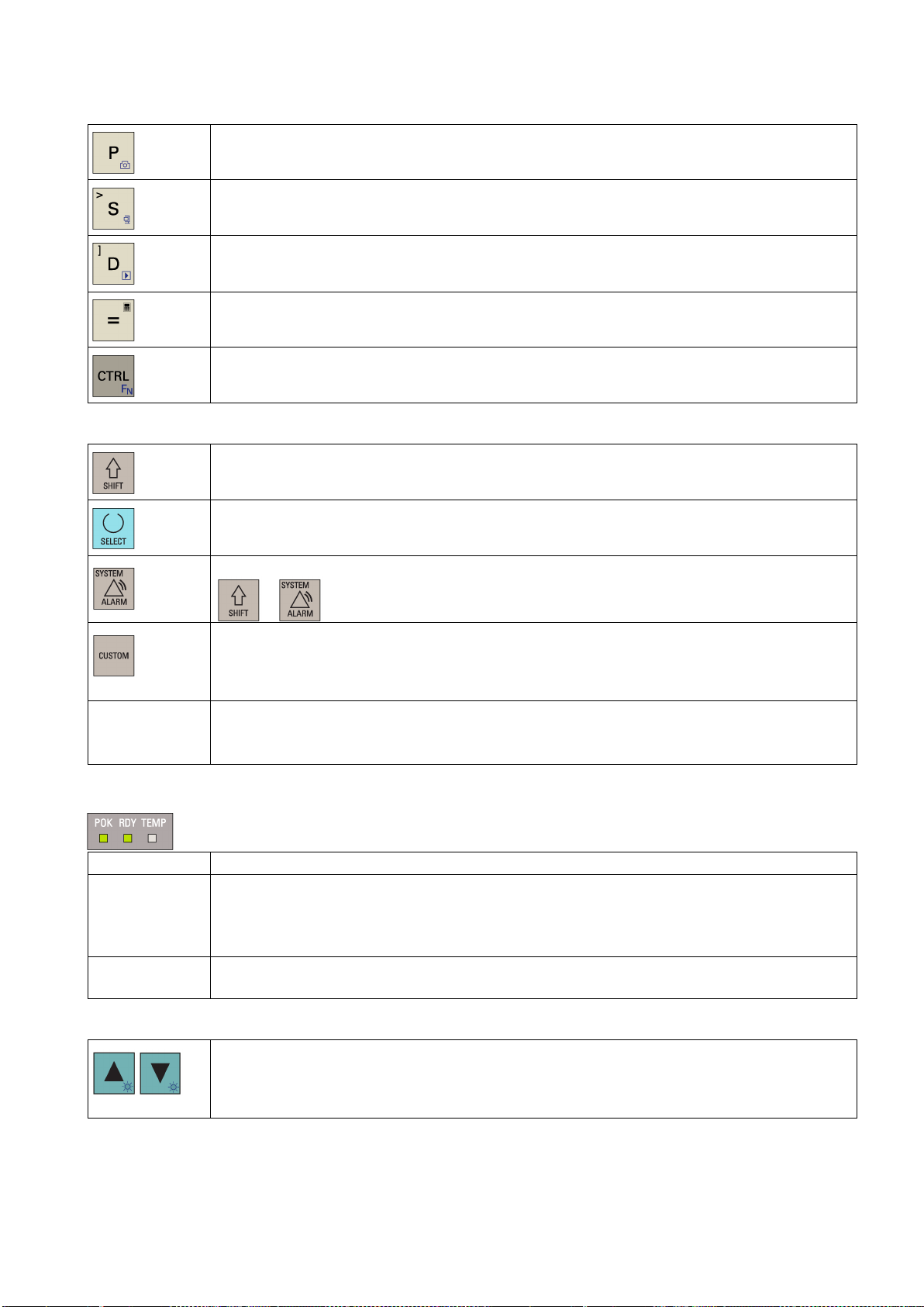
Keys with icons
Further information
The icon on the key is a hint that you can press both <CTRL> and this key as shortcuts for capturing
screens.
The icon on the key is a hint that you can press both <CTRL> and this key as shortcuts for saving
start-up archives and action logs to a USB stick.
The icon on the key is a hint that you can press both <CTRL> and this key as shortcuts for displaying
pre-defined slides on the screen or both <ALT> and this key as shortcuts for saving action logs to a
USB stick.
The icon on the key is a hint that you can press this key to call the calculator function.
The icon on the key is a hint that this key can be used together with another key to function as a key
combination.
To enter the upper character on an alphabetic/numeric/operating area key, keep this key pressed.
• Toggles between entries in the input field
• Enters the "Set-up menu" dialog at NC start-up
To open the system data management operating area, press the following key combination:
USB interface Connects to a USB device, for example:
Status LEDs
LED "POK" Solid green: The power supply for the CNC is switched on.
LED "RDY"
LED "TEMP"
Backlight brightness control
+
Enables user-defined extension applications, for example, generation of user dialogs with the
EasyXLanguage function.
For more information about this function, see the SINUMERIK 808D/SINUMERIK 808D ADVANCED
Function Manual.
• An external USB memory stick, to transfer data between the USB stick and the CNC
• An external USB keyboard which functions as an external NC keyboard
• Solid green: The CNC is ready and the PLC is in running mode.
• Solid red: The CNC is in stop mode.
• Solid orange: The PLC is in stop mode.
• Flashing orange: The PLC is in power-up mode.
• Off: The CNC temperature is within the specified range.
• Solid orange: The CNC temperature is out of range.
Pressing <CTRL> and the cursor keys sets the screen backlight brightness by an increment of 10%
(brightness range: 10% to 100%).
Note that after you release the key combination, the HMI saves your brightness settings and the
brightness bar disappears after three seconds.
Programming and Operating Manual (Turning)
6FC5398-5DP10-0BA2, 06/2015
9
2.2
Machine control panels
2.2.1
Machine Control Panel (MCP) versions
MCP version
Applicable control system
Vertical MCP with an override switch for the spindle, Chinese version
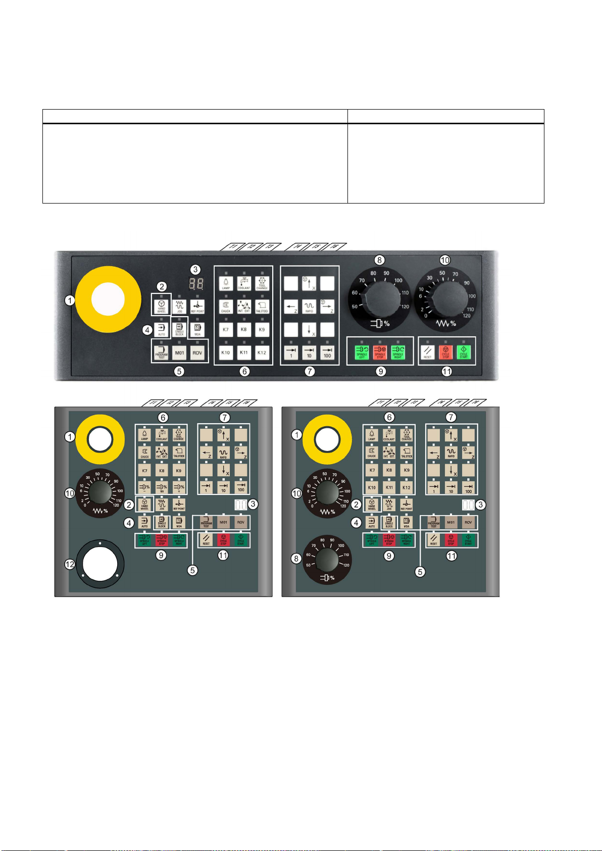
2.2.2
Control elements on the MCP
①
Reserved hole for emergency stop button
⑦
Axis traversing keys
②
Handwheel key
⑧
Spindle override switch
for the handwheel)
③
Tool number display
Displays the current tool number
⑨
Spindle state keys
④
Operating mode keys
⑩
Feedrate override switch
override
⑤
Program control keys
⑪
Keys for program start, stop, and reset
⑥
User-defined keys
⑫
Reserved slot for the handwheel
• Horizontal MCP, English version
• Horizontal MCP, Chinese version
• Vertical MCP with a reserved slot for the handwheel, English version
• Vertical MCP with a reserved slot for the handwheel, Chinese version
• Vertical MCP with an override switch for the spindle, English version
•
SINUMERIK 808D ADVANCED T (Turning)/M
(Milling)
Controls the axis movement with external handwheels
Programming and Operating Manual (Turning)
10 6FC5398-5DP10-0BA2, 06/2015
(unavailable for the vertical MCP with a reserved slot
Traverses the selected axis at the specified feedrate
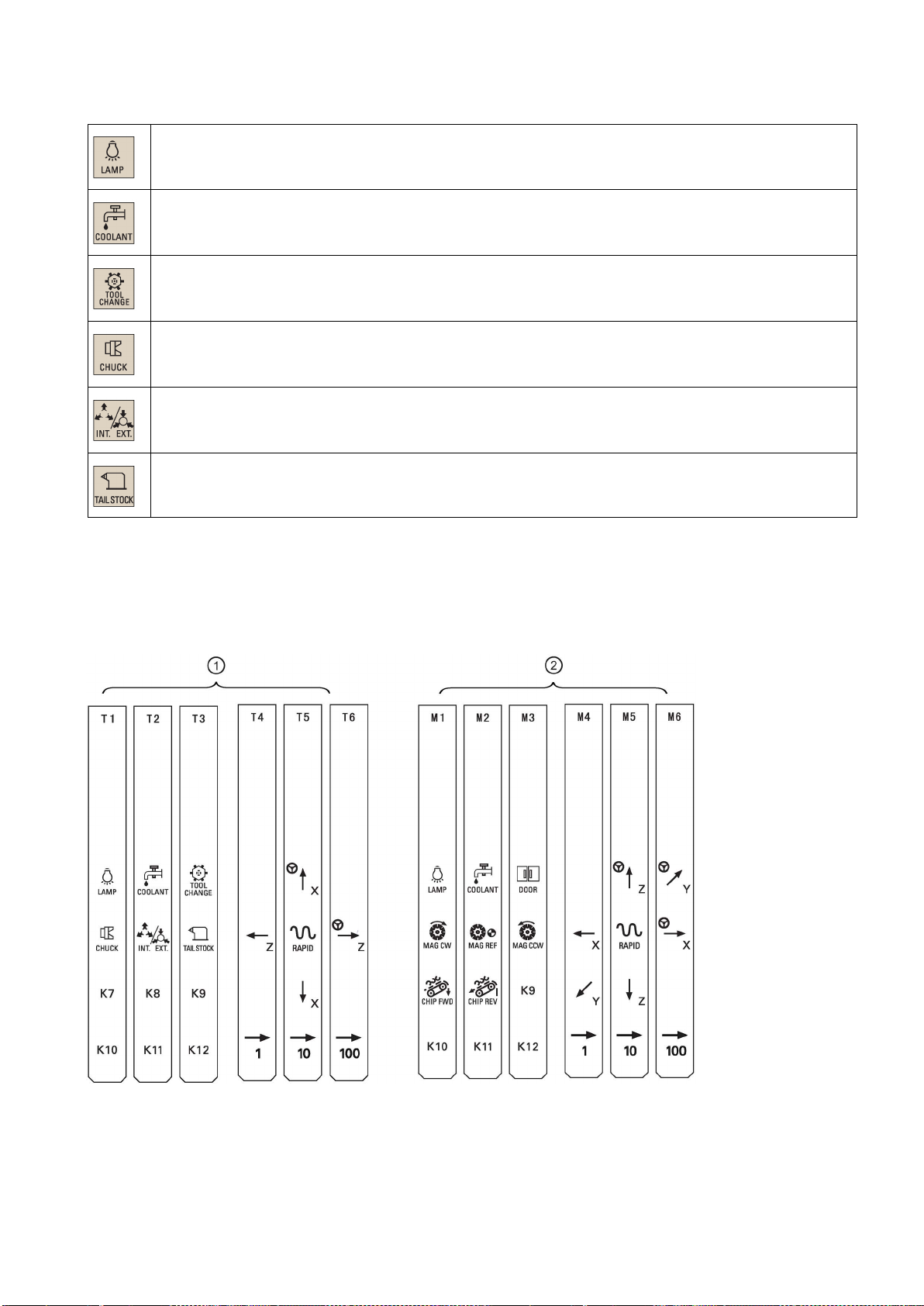
User-defined keys
Pre-defined insertion strips
Pressing this in any operating mode switches on/off the lamp.
LED on: The lamp is switched on.
LED off: The lamp is switched off.
Pressing this key in any operating mode switches on/off the coolant supply.
LED on: The coolant supply is switched on.
LED off: The coolant supply is switched off.
Pressing this key starts sequential tool changes (active only in "JOG" mode).
LED on: The machine starts sequential tool changes
LED off: The machine stops sequential tool changes
Pressing this key in any operating mode activates the chuck to clamp/unclamp the workpiece.
LED on: Activates the chuck to clamp the workpiece
LED off: Activates the chuck to unclamp the workpiece
Pressing this key only when the spindle stops operation.
LED on: Activates the external chuck to clamp the workpiece inwards
LED off: Activates the internal chuck to clamp the workpiece outwards
Pressing this key in any operating mode advances/retracts the tailstock.
LED on: Advances the tailstock towards the workpiece until it firmly engages with the end of the workpiece
The MCP package includes two sets (six pieces each) of pre-defined insertion strips. One set is for the turning variant of the
control system and is pre-inserted on the back of the MCP. The other set is for the milling variant of the control system.
If your control system is a milling variant of the control system, replace the pre-inserted strips with the milling-specific
insertion strips.
Programming and Operating Manual (Turning)
6FC5398-5DP10-0BA2, 06/2015
11
Customized insertion strips
Note
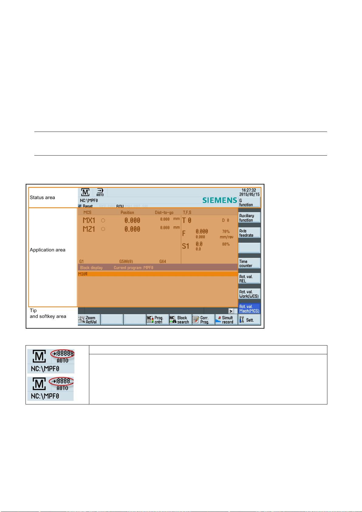
2.3
Screen layout
Display of variable increments in the status area
The MCP package also includes an A4-sized blank plastic sheet with detachable strips. You can customize insertion strips if
the pre-defined strips cannot meet your needs.
In the \examples\SINUMERIK_808D_ADVANCED\MCP folder of the Toolbox DVD for the control system, there is a symbol
library file and an insertion strip template file. To make customized insertion strips, follow the steps below:
1. Copy the desired symbols from the symbol library file to the desired locations in the insertion strip template.
2. Print the template to the A4-sized blank plastic sheet.
3. Detach the insertion strips from the blank plastic sheet.
4. Pull out the pre-inserted strips from the MCP.
5. Insert the customized strips on the back of the MCP.
This manual assumes a SINUMERIK 808D ADVANCED standard MCP. Should you use a different MCP, the operation
may be other than described herein.
Displays the variable increment if it is defined in the standard subroutine program
• Value ≤ five digits: displays the complete value
• Value > five digits: displays the first four digits plus ".."
Programming and Operating Manual (Turning)
12 6FC5398-5DP10-0BA2, 06/2015
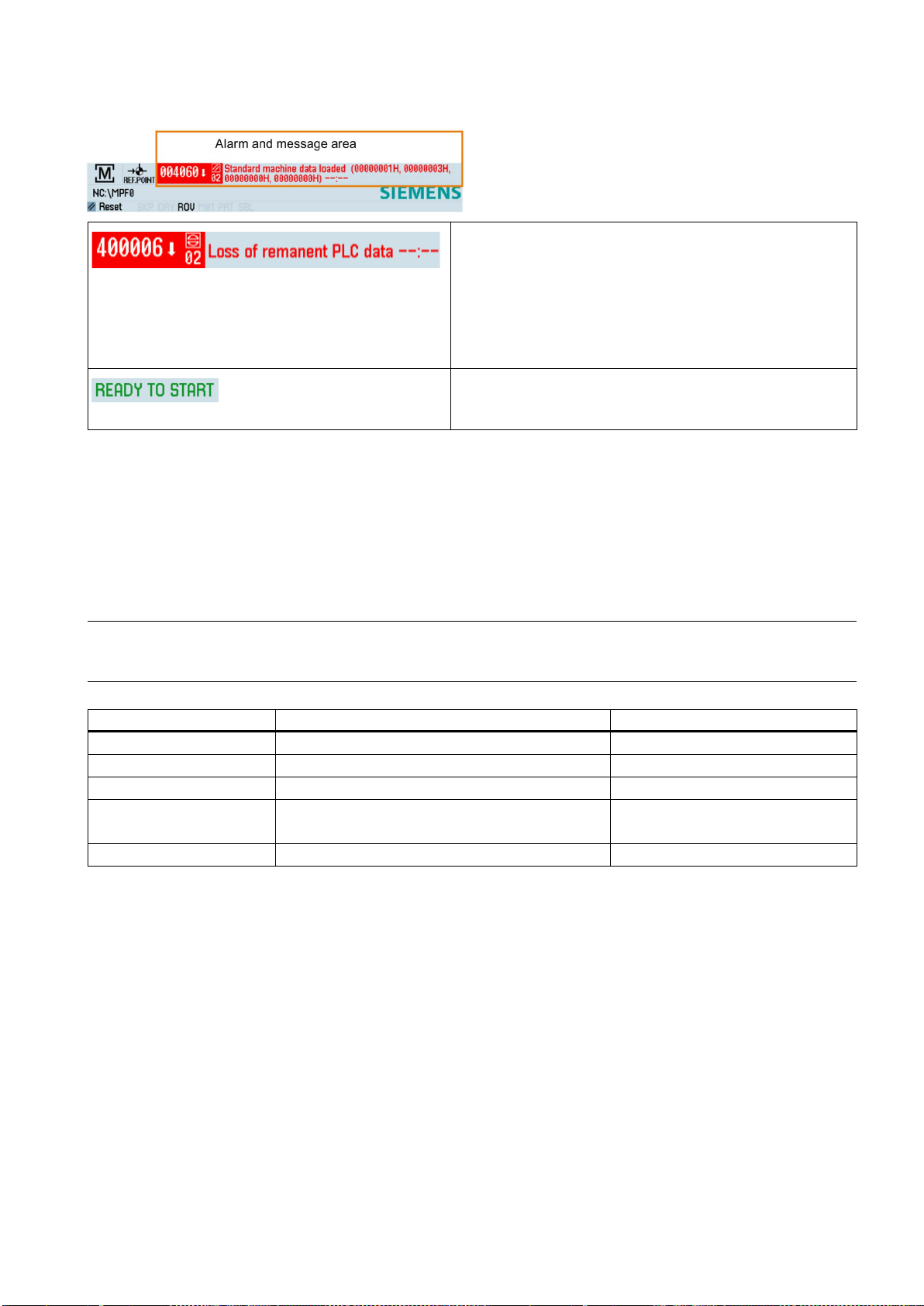
Alarms and messages
Displays active alarms with alarm text
Displays messages from NC programs
2.4
Protection levels
Overview
Note
Protection level
Locked by
Area
0
1
2
3-6
7
Protection level 1
Protection level 3-6
The alarm number is displayed in white lettering on a red background. The associated alarm text is shown in red lettering. An
arrow indicates that several alarms are active. The number to
the right of the arrow indicates the total number of active
alarms. When more than one alarm is active, the display scrolls
through the alarms in sequence. An acknowledgement symbol
indicates the alarm cancel criterion.
Messages from NC programs do not have numbers and appear
in green lettering.
The control system provides a concept of protection levels for enabling data areas. Different protection levels control
different access rights.
The control system delivered by Siemens is set by default to the lowest protection level 7 (without password). If the
password is no longer known, the control system must be reinitialized with the default machine/drive data. All passwords are
then reset to default passwords for this software release.
Before you boot the control system with default machine/drive data, make sure that you have backed up your machine/drive
data; otherwise, all data are lost after rebooting with default machine/drive data.
Siemens password Siemens, reserved
Manufacturer password Machine manufacturers
Reserved
End user password
(Default password: "CUSTOMER")
No password End users
Protection level 1 requires a manufacturer password. With this password entry, you can perform the following operations:
● Entering or changing part of the machine data and drive data
● Conducting NC and drive commissioning
Protection level 3-6 requires an end user password. With this password entry, you can perform the following operations:
● Entering or changing part of the machine data
● Editing programs
● Setting offset values
● Measuring tools
End users
Programming and Operating Manual (Turning)
6FC5398-5DP10-0BA2, 06/2015
13
Protection level 7
USER_CLASS
Setting password
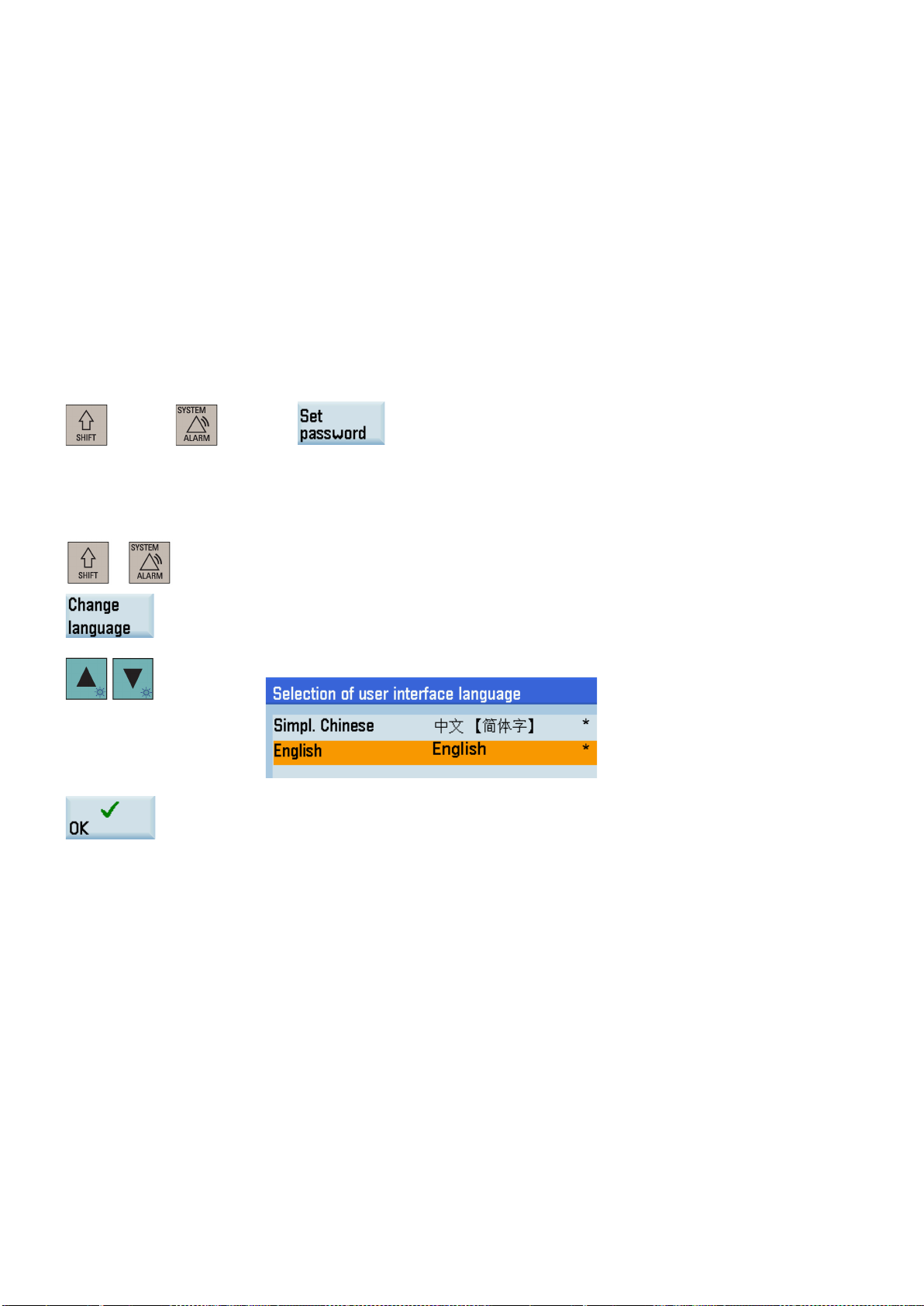
2.5
Setting user interface language
Operating sequence
Note:
Protection level 7 is set automatically if no password is set and no protection level interface signal is set. The protection level
7 can be set from the PLC user program by setting the bits in the user interface.
In the menus listed below the input and modification of data depends on the set protection level:
● Tool offsets
● Work offsets
● Setting data
● Program creation/program correction
The number of machine data and drive data which can be read or modified depends on the protection level. You can set the
protection level for these function areas with the display machine data (
You can set the desired password through the following operating area:
+
+
→
1. Select the desired operating area.
2. Press this softkey to open the user interface language selection window.
...).
3. Use the cursor keys to select the desired language.
4. Press this softkey to confirm your selection.
The HMI (Human Machine Interface) is automatically restarted when a new language is
selected.
Programming and Operating Manual (Turning)
14 6FC5398-5DP10-0BA2, 06/2015
3
Turning on, reference point approach
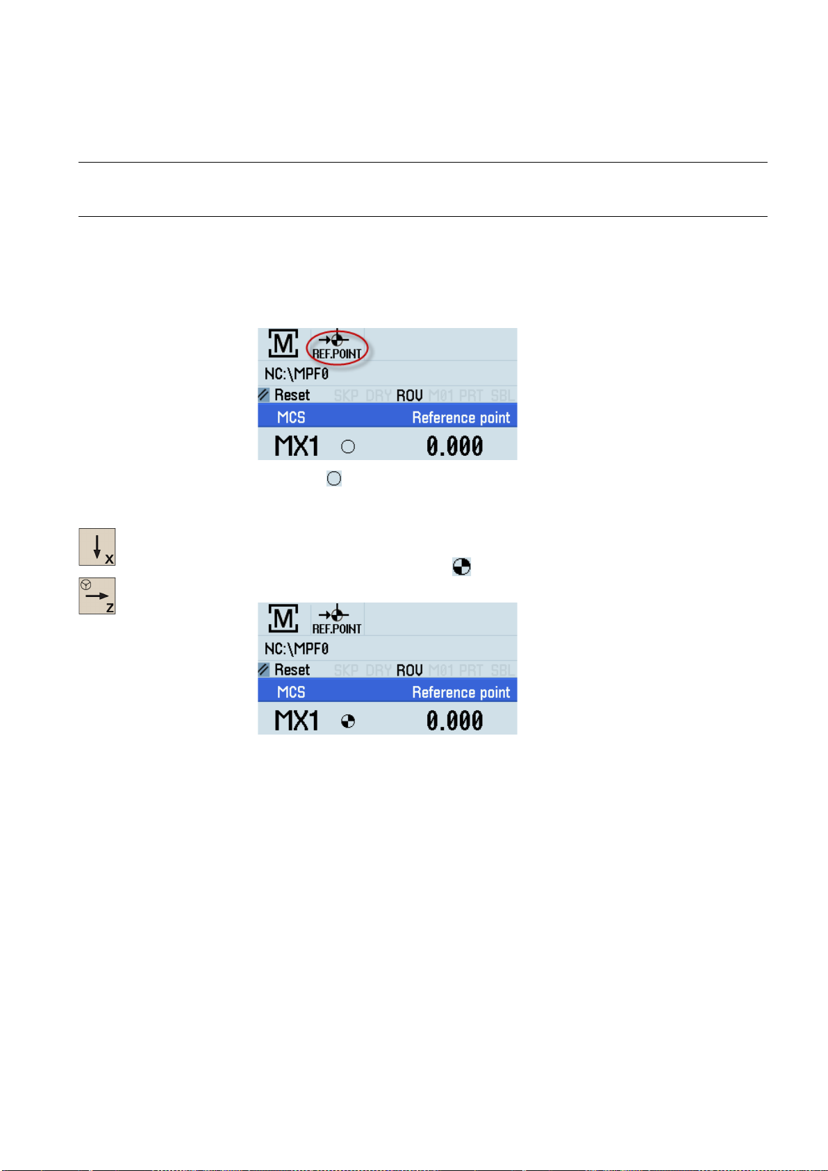
Note
Operating sequence
d, the symbol is always visible in the current (machining) operating
When turning on the CNC and the machine, also observe the machine tool manufacturer's documentation, since turning-on
and reference point approach are machine-dependent functions.
1. Switch on the power supply for the control system and the machine.
2. Release all emergency stop buttons on the machine.
By default, the control system is in the "REF.POINT" window after booting.
The symbol
If an axis is not reference
area.
3. Press the corresponding axis traversing keys on the MCP to traverse each axis to the reference point.
Note that axis traversing directions and axis key functions are defined by the machine man-
If the axis is referenced, a symbol (
in the "REF.POINT" window.
ufacturer.
shown next to the axis identifier indicates that the axis is not yet referenced.
) appears next to the axis identifier and is visible only
Programming and Operating Manual (Turning)
6FC5398-5DP10-0BA2, 06/2015
15
4
Setting-up
4.1
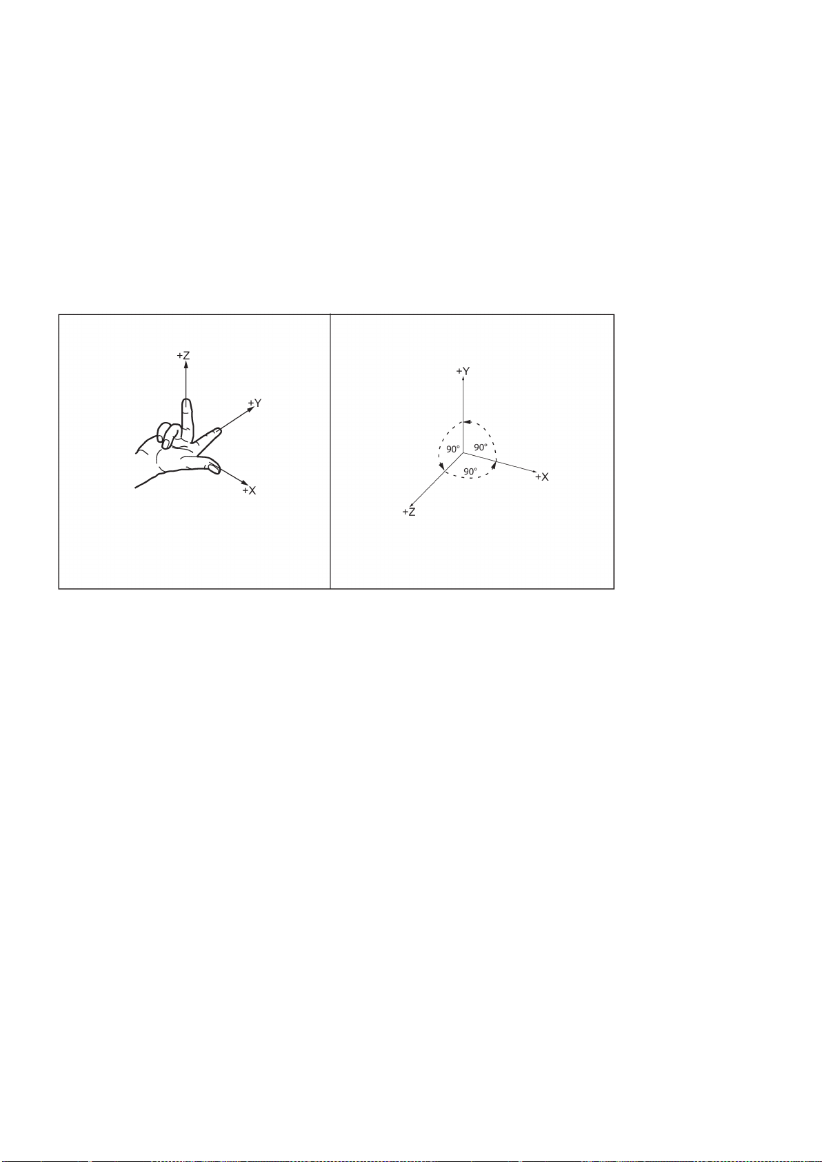
Coordinate systems
Machine coordinate system (MCS)
As a rule, a coordinate system is formed from three mutually perpendicular coordinate axes. The positive directions of the
coordinate axes are defined using the so-called "3-finger rule" of the right hand. The coordinate system is related to the
workpiece and programming takes place independently of whether the tool or the workpiece is being traversed. When
programming, it is always assumed that the tool traverses relative to the coordinate system of the workpiece, which is
intended to be stationary.
The figure below illustrates how to determine the axis directions.
The orientation of the coordinate system relative to the machine depends on the machine type. It can be rotated in different
positions.
The directions of the axes follow the "3-finger rule" of the right hand. Seen from the front of the machine, the middle finger of
the right hand points in the opposite direction to the infeed of the spindle.
Programming and Operating Manual (Turning)
16 6FC5398-5DP10-0BA2, 06/2015
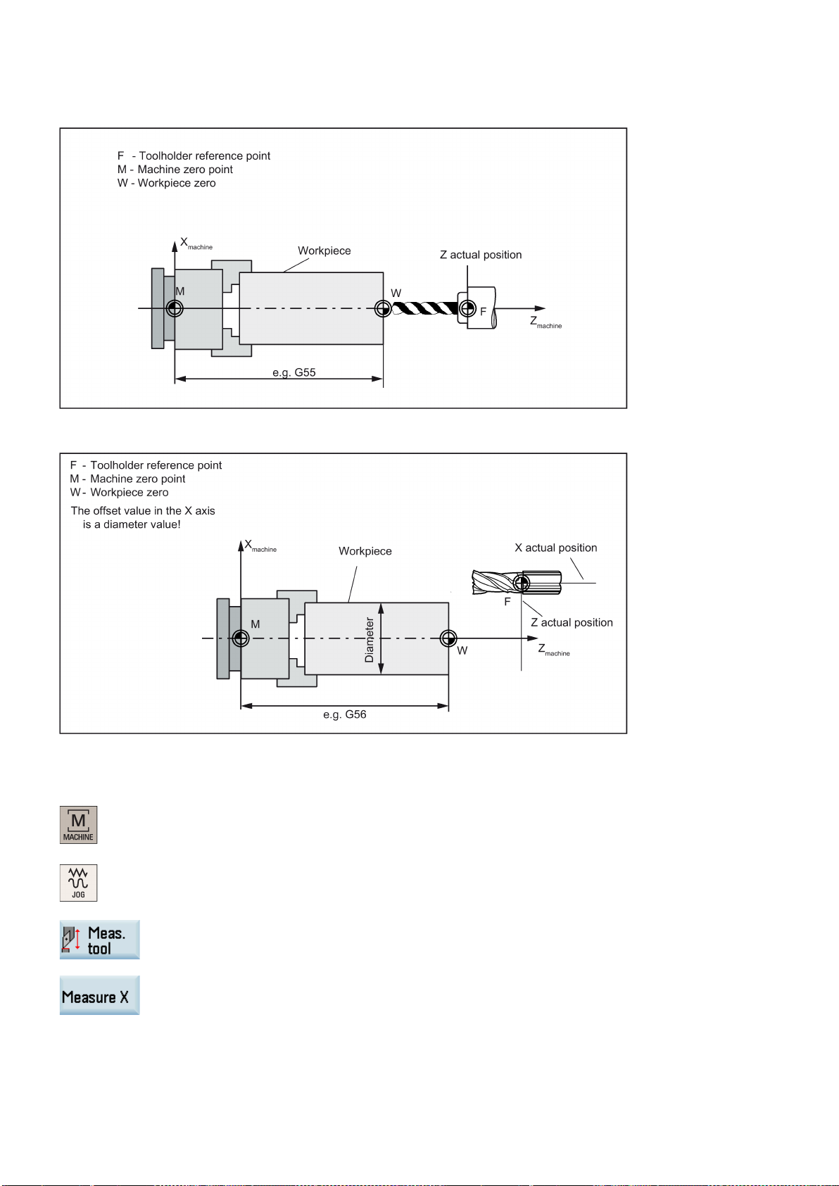
machine zero.
machine axes
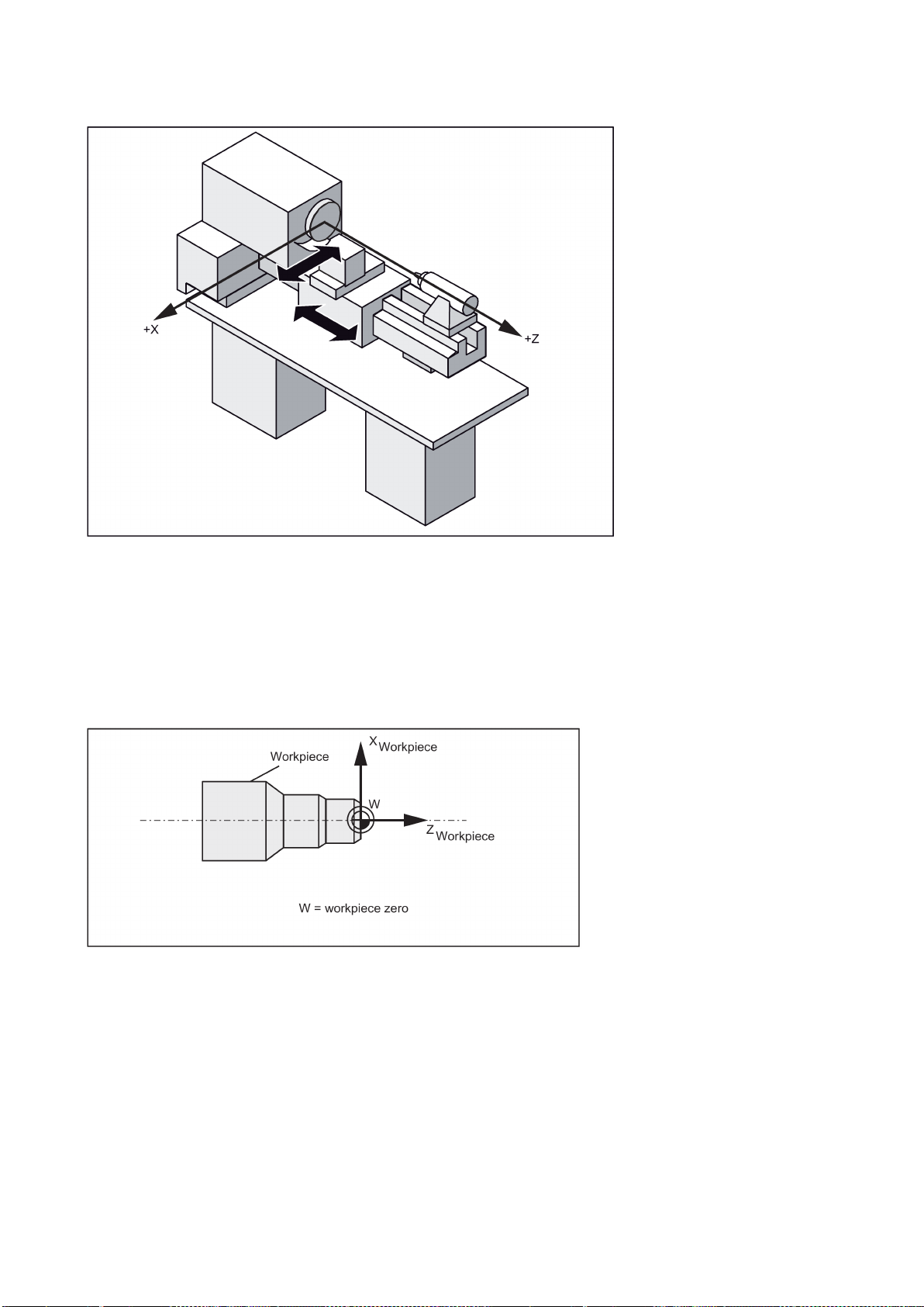
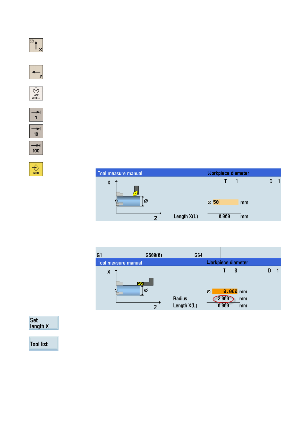
Workpiece coordinate system (WCS)
workpiece zero
Relative coordinate system (REL)
Clamping the workpiece
settable work
offset
G54
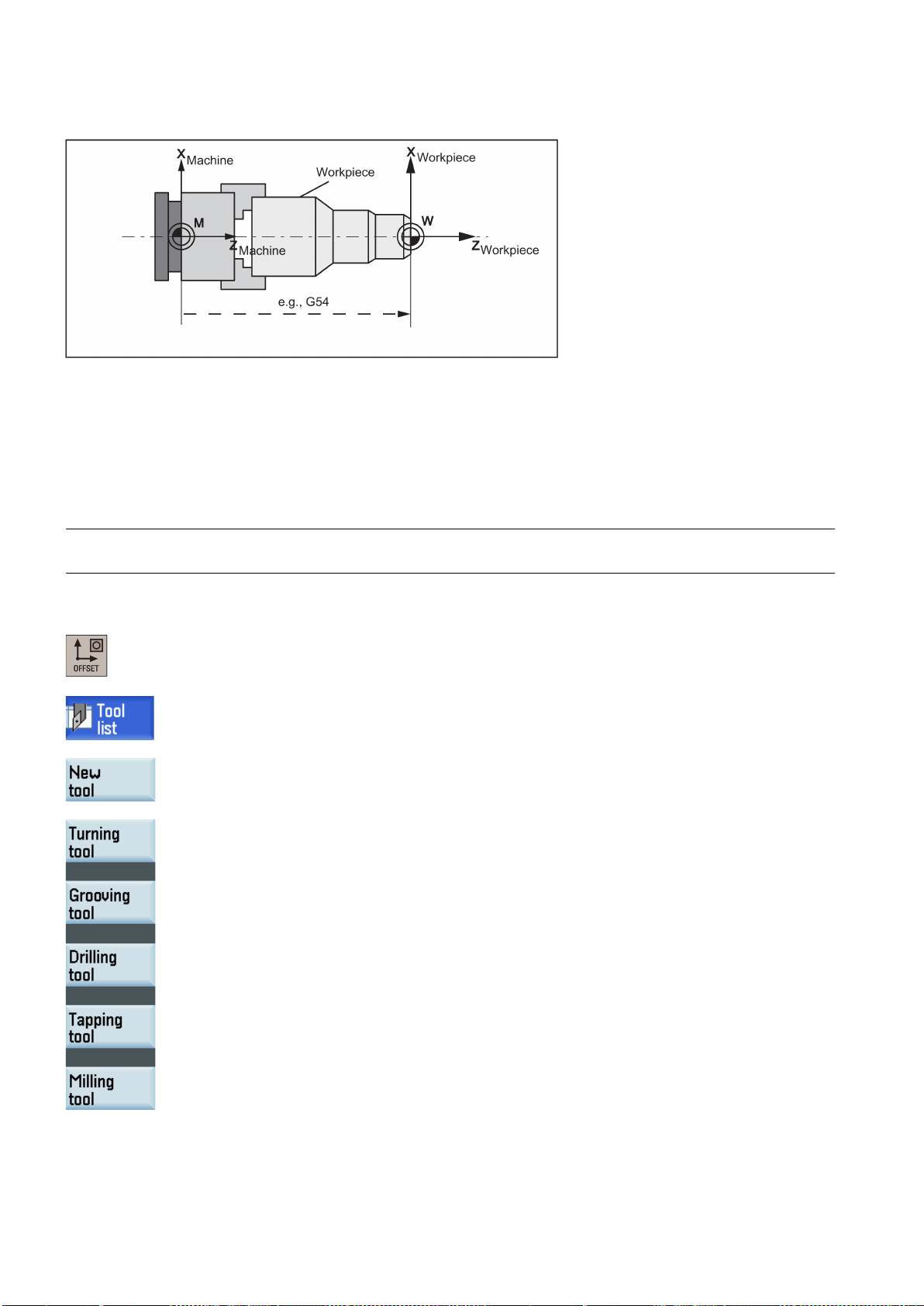
The figure below shows an example of the machine coordinate system of a turning machine.
The origin of this coordinate system is the
This point is only a reference point which is defined by the machine manufacturer. It does not have to be approachable.
The traversing range of the
To describe the geometry of a workpiece in the workpiece program, a right-handed, right-angled coordinate system is also
used.
The
The figure below shows an example of the workpiece coordinate system.
In addition to the machine and workpiece coordinate systems, the control system provides a relative coordinate system. This
coordinate system is used to set reference points that can be freely selected and have no influence on the active workpiece
coordinate system. All axis movements are displayed relative to these reference points.
can be freely selected by the programmer in the Z axis. In the X axis, it lies in the turning center.
can be in the negative range.
For machining, the workpiece is clamped on the machine. The workpiece must be aligned such that the axes of the
workpiece coordinate system run in parallel with those of the machine. Any resulting offset of the machine zero with
reference to the workpiece zero is determined along the Z axis and entered in a data area intended for the
. In the NC program, this offset is activated during program execution, for example, using a programmed
command.
Programming and Operating Manual (Turning)
6FC5398-5DP10-0BA2, 06/2015
17
Current workpiece coordinate system
4.2
Setting up tools
4.2.1
Creating a new tool
Note
Operating sequence
The figure below shows an example of the workpiece clamped on the machine.
The programmed work offset TRANS (Page 56) can be used to generate an offset with reference to the workpiece
coordinate system, resulting in the current workpiece coordinate system.
The control system supports a maximum of 64 tools or 128 cutting edges.
1. Select the desired operating area.
2. Open the tool list window.
3. Open the lower-level menu for tool type selection.
4. Select a desired tool type with the corresponding softkey.
Programming and Operating Manual (Turning)
18 6FC5398-5DP10-0BA2, 06/2015

5. Enter the tool number (value range: 1 to 31999; preferentially enter a value less than 100)
and select the corresponding tool edge position code according to the actual tool point direction in the following windows:
• Available edge positions for turning tool and grooving tool: 1, 2, 3 and 4 (taking new
turning tool as an example)
• Available edge positions for drilling tool, tapping tool and milling tool: 5, 6, 7 and 8
(taking new milling tool as an example)
6. Use this softkey to confirm your settings. The window below shows the information of the
new tool created.
① Tool type
② Tool number
③ Tool offset number
④ Tool offset number
⑤ Tool length in the X and Z axes
⑥ Tool radius
⑦ Clearance angle
⑧ Tip width of the cutting edge, which is only active for the grooving tool
⑨ Cutting edge direction
Programming and Operating Manual (Turning)
6FC5398-5DP10-0BA2, 06/2015
19
Note:
4.2.2
Activating the tool
Operating sequence
7. Enter the tool radius data or tool tip width as desired and confirm your settings.
1. Select the desired operating area.
2. Switch to "JOG" mode.
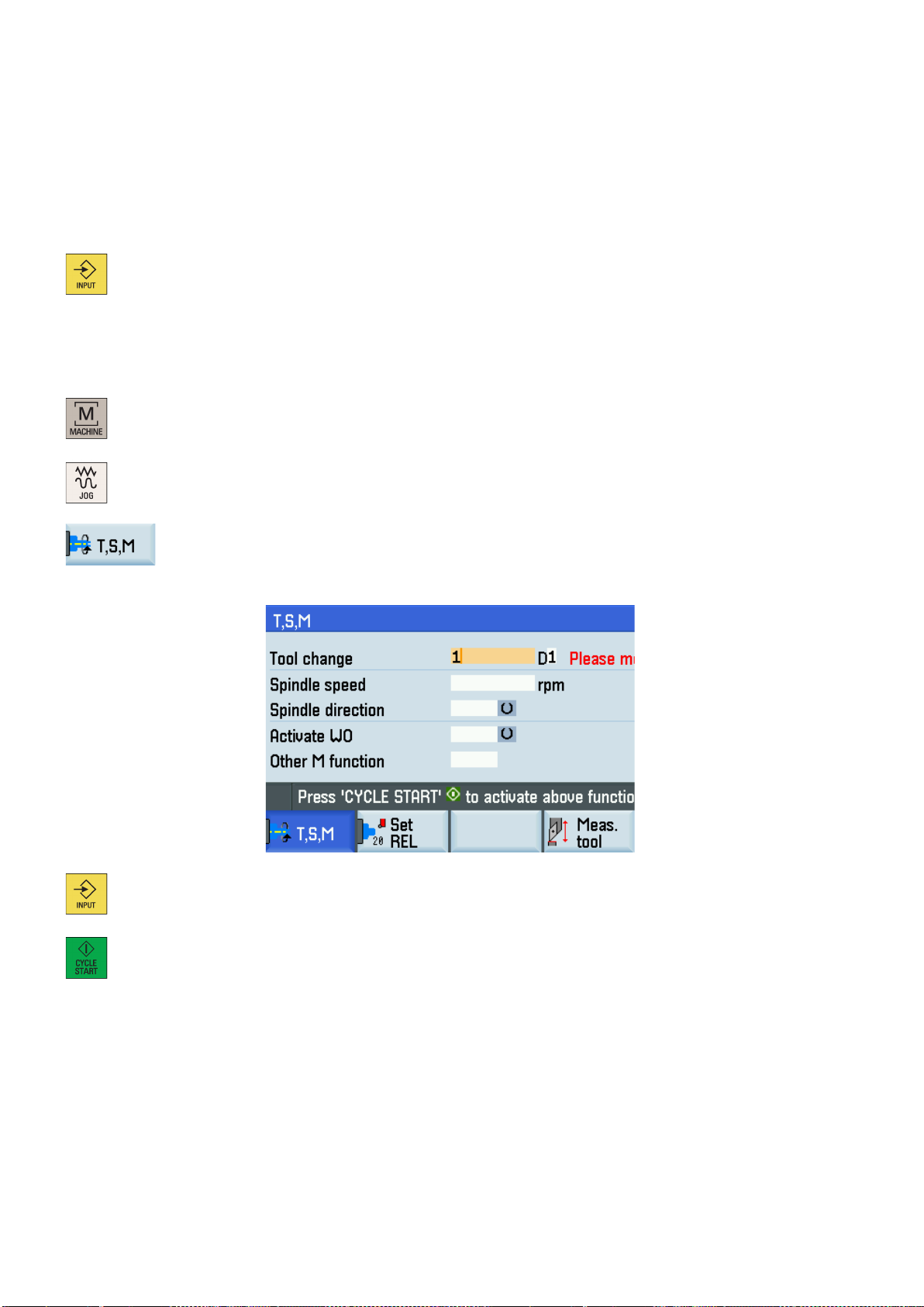
3. Open the "T, S, M" window.
4. Enter the desired tool number (for example, 1) in the "T, S, M" window.
• Column ④ is invisible in Siemens mode. The function of activating the compensation
data via the "H" column is active only in ISO dialect mode.
• Column
40000H. By default, MD19730 = 0H. Note that MD19730 is visible only with the
manufacturer password. For more information about the clearance angle, see the
SINUMERIK 808D/SINUMERIK 808D ADVANCED Function Manual.
⑦ is visible only when you set bit 18 of MD19730 to 1, that is, MD19730 =
5. Use this key or move the cursor to confirm your entries.
6. Press this key on the MCP to activate the tool.
Programming and Operating Manual (Turning)
20 6FC5398-5DP10-0BA2, 06/2015

4.2.3
Assigning the handwheel
Method 1: Assigning through the PPU
ey to activate the value change. Note that the control system restarts
1. Select the desired operating area.
+
2. Open the machine data window.
3. Press this softkey to open the basic machine data list.
4. Use the cursor keys or the following softkey to search for the general machine data "14512
5. Select bit 7 by using the following key and cursor keys:
USER_DATA_HEX[16]".
Press the following softkey to confirm your input.
6. Press this vertical softk
to accept the new value.
7. After the control system has booted, select the desired operating area.
8. Press this key on the MCP.
9. Press this key to view more menu options.
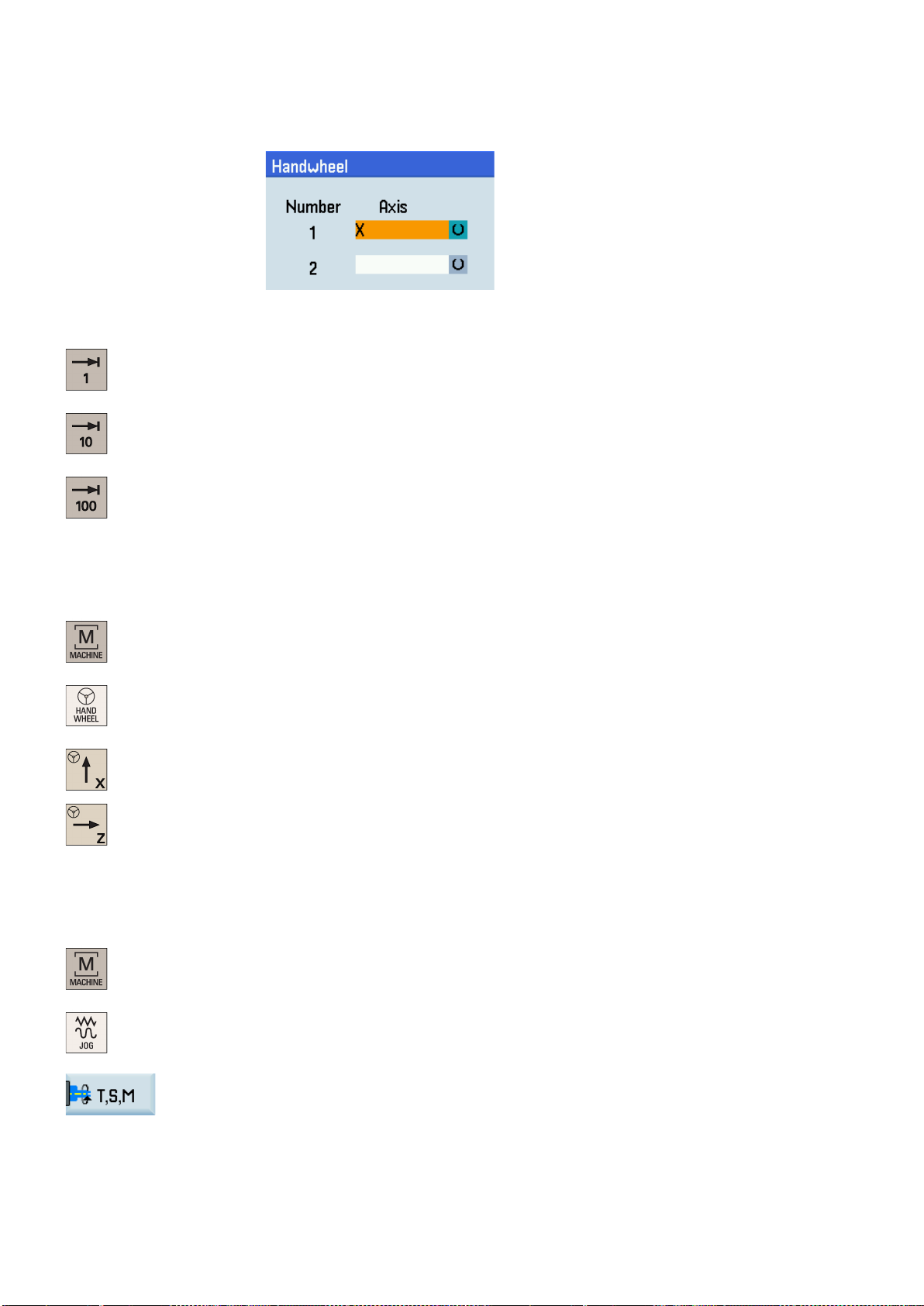
10. Open the handwheel assignment window.
11. Select the desired handwheel number with the cursor keys.
12. Press the desired vertical softkey (<X> ... <MZ1>) or the following key for the handwheel
assignment.
Programming and Operating Manual (Turning)
6FC5398-5DP10-0BA2, 06/2015
21
Select the required override increment with the following axis traversing keys on the MCP to
Method 2: Assigning through the MCP
Precondition:
4.2.4
Activating the spindle
Operating sequence
The axis identifier (for example, "X") which appears in the window indicates that you have
assigned the handwheel to the selected axis.
13.
move the selected axis.
The override increment is 0.001 mm.
The override increment is 0.010 mm.
The override increment is 0.100 mm.
MD14512[16].7 = 0 (factory default)
1. Select the desired operating area.
2. Press this key on the MCP to control the axis movement with external handwheels.
3. Press the desired axis traversing keys to assign the handwheel.
1. Select the desired operating area.
2. Switch to "JOG" mode.
3. Open the "T, S, M" window.
4. Enter the desired value for the spindle speed in the "T, S, M" window.
Programming and Operating Manual (Turning)
22 6FC5398-5DP10-0BA2, 06/2015
4.2.5
Measuring the tool (manually)
Overview
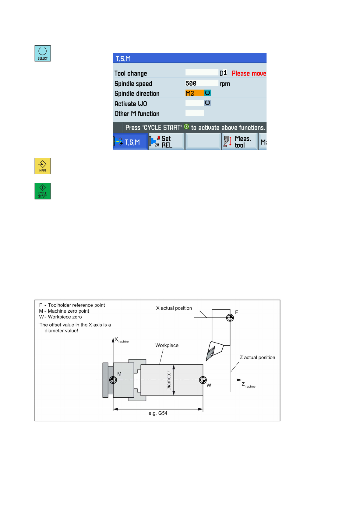
5. Press this key to select the spindle direction.
6. Use this key or move the cursor to confirm your entries.
7. Press this key on the MCP to activate the spindle.
The geometries of the machining tool must be taken into consideration when you execute a part program. These are stored
as tool offset data in the tool list. Each time the tool is called, the control considers the tool offset data.
You can determine the tool offset data, including the length, radius and diameter by either measuring the tool or entering the
values in the tool list (for more information, see Section "Creating a new tool (Page 18)").
As per the actual position of the point F (the machine coordinate) and the reference point, the control system can calculate
the offset value assigned to the lengths for the X and Z axes.
See the following illustration for determining the length offsets using the example of a turning tool:
Programming and Operating Manual (Turning)
6FC5398-5DP10-0BA2, 06/2015
23
Operating sequence
Measuring the tool in the X direction
See the following illustration for determining the length offsets using the example of a drill: Length 1/Z axis
See the following illustration for determining the length offsets using the example of a milling tool:
1. Select the desired operating area.
2. Switch to "JOG" mode.
3. Open the manual tool measurement window.
4. Press this vertical softkey to measure the tool in the X direction.
Programming and Operating Manual (Turning)
24 6FC5398-5DP10-0BA2, 06/2015
override feedrate, and then use the handwheel to move the tool to scratch
Note:
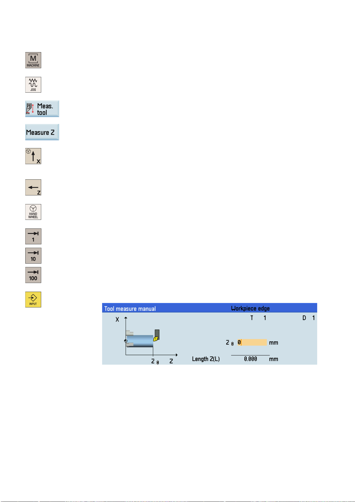
Save the length value in the X axis. The tool diameter, radius, and cutting edge position are
...
5. Move the tool to approach the workpiece in the X direction.
6. Switch to handwheel control mode.
7. Select a suitable
the required workpiece edge (or the edge of the setting block, if it is used).
8. Enter the workpiece diameter in the "Ø" field (for example, 50).
For a milling tool with edge position 5 or 7, the radius of the tool itself is displayed in the
following window:
9.
all taken in to account.
10. Press this softkey and you can see that the compensation data values have been automatically added to the tool data.
Programming and Operating Manual (Turning)
6FC5398-5DP10-0BA2, 06/2015
25
Measuring the tool in the Z direction
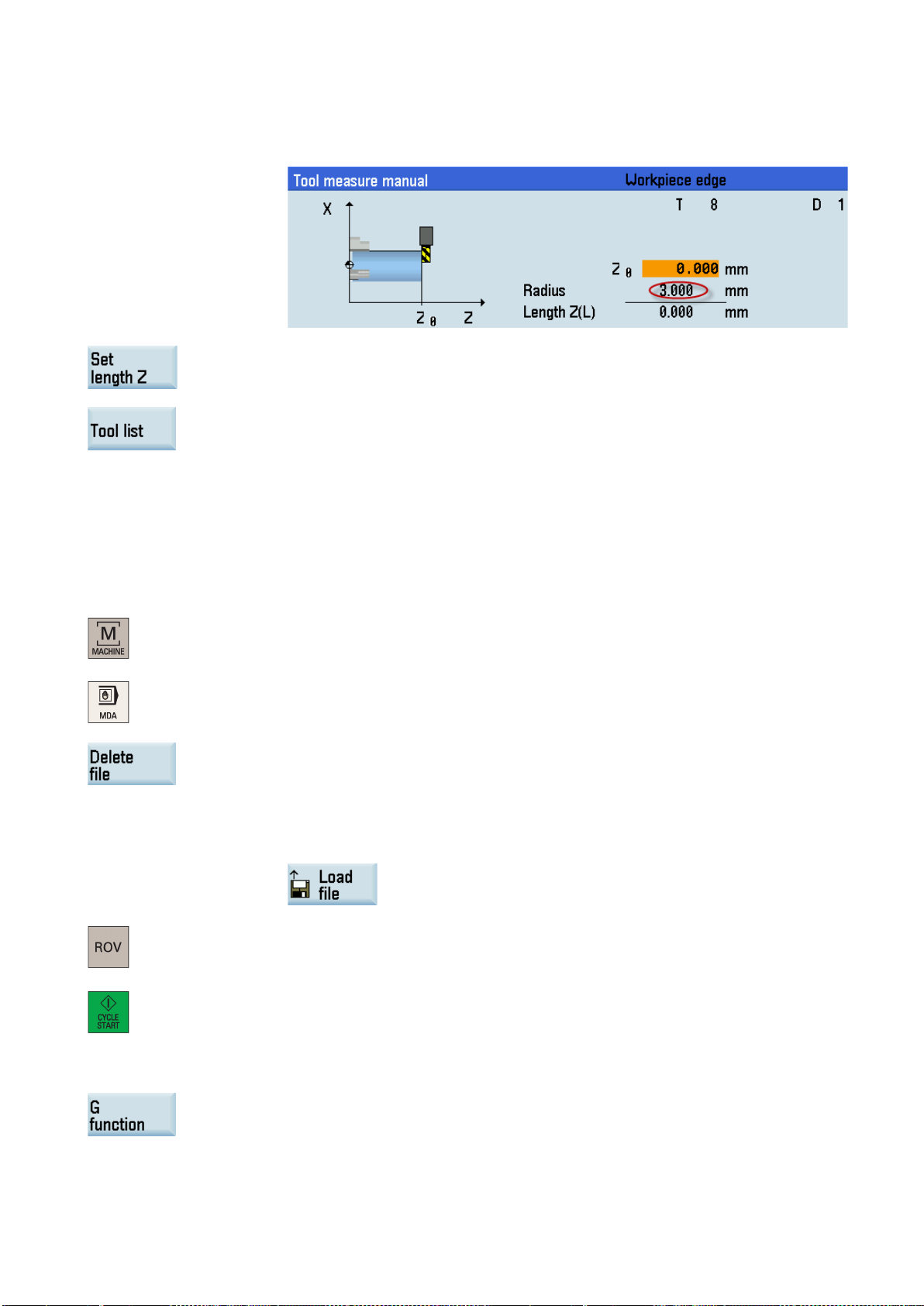
Select a suitable override feedrate, and then use the handwheel to move the tool to scratch
1. Select the desired operating area.
2. Switch to "JOG" mode.
3. Open the manual tool measurement window.
4. Press this vertical softkey to measure the tool in the Z direction.
5. Move the tool to approach the workpiece in the Z direction.
...
6. Switch to handwheel control mode.
7.
the required workpiece edge (or the edge of the setting block, if it is used).
8. Enter the distance between the tool tip and the workpiece edge in the "Z0" field, for example, "0". (This value is the thickness of a setting block if it is used.)
Programming and Operating Manual (Turning)
26 6FC5398-5DP10-0BA2, 06/2015
Note:
4.2.6
Verifying the tool offset result in "MDA" mode
Operating sequence
Note:
Further softkey functions in "MDA" mode
9. Save the length value in the Z axis.
10. Press this softkey and you can see that the compensation data values have been automati-
Repeat the above operations for other tools and make sure you measure all the tools before machining, which also eases
the tool changing process.
In order to ensure the machine safety and correctness, you must test the results of the tool offset appropriately.
For a milling tool with edge position 6 or 8, the radius of the tool itself is displayed in the
following window:
cally added to the tool data.
1. Select the desired operating area.
2. Switch to "MDA" mode.
3. Press this softkey on the PPU.
4. Enter the test program, for example: G500 T1 D1 G00 X0 Z5.
You can alternatively load an existing part program from a system directory using the follow-
ing softkey if desired:
5. Press this key to ensure the "ROV" function is active (LED on).
The "ROV" function activates the feedrate override switch under the G00 function.
6. Press this key on the MCP.
Increase the feedrate override gradually to avoid accidents caused by an axis moving too
fast and observe whether the axis moves to the set position.
This window displays important G functions whereby each G function is assigned to a group and
has a fixed position in the window. To close the window, press this softkey once again.
Programming and Operating Manual (Turning)
6FC5398-5DP10-0BA2, 06/2015
27
This window displays the auxiliary and M functions currently active. To close the window, press this
a name and a storage medium for
Note:
4.2.7
Entering/modifying the tool wear data
Note
Operating sequence
To display additional G functions, use the corresponding keys.
softkey once again.
This softkey opens the file saving window where you can specify
the program displayed in the MDA window. To save your program, either enter a new program
name in the input field or select an existing program for overwriting.
If you do not save with this softkey, the program edited in "MDA" mode is actually a temporary file.
Pressing this softkey deletes all the blocks displayed in the MDA window.
This softkey opens a window where you can select an existing program file from a system directory
to load into the MDA buffer.
For the explanation of other softkeys in this mode, see Section "Other settings in "JOG" mode (Page 202)".
For the explanation of part programming in "MDA" mode, see Section "Notes on part programs in "MDA" mode (Page 207)".
You must distinguish the direction of tool wear compensation clearly.
1. Select the desired operating area.
2. Open the tool wear window.
3. Use the cursor keys to select the required tools and their edges.
4. Enter the tool length wear parameter of axis X and axis Z as well as the tool radius wear
parameter.
Positive value: The tool moves away from the workpiece.
Negative value: The tool moves closer to the workpiece.
Programming and Operating Manual (Turning)
28 6FC5398-5DP10-0BA2, 06/2015

4.3
Operating area overview
Softkey functions
①
Displays and modifies the tool offsets
②
Displays and modifies the tool wear data
③
Displays and modifies the work offsets
④
Displays and modifies the R variables
⑤
Configures and displays lists of setting data
⑥
Displays the defined user data
⑦
Measures the tool manually
⑧
For more information, see Section "Creating a new tool (Page 18)".
⑨
For more information, see Section "Creating a new cutting edge (Page 194)".
⑩
Removes the currently selected tool from the tool list
⑪
Searches for your desired tool with the tool number
5. Press this key or move the cursor to activate the compensation.
When working with the CNC, you need to set up the machine and the tools, etc. as follows:
● Create the tools and cutting edges.
● Enter/modify the tool and work offsets.
● Enter the setting data.
Pressing this key on the PPU allows you to open the following window:
Creates a new tool
Opens a lower-level menu for cutting edge settings
Programming and Operating Manual (Turning)
6FC5398-5DP10-0BA2, 06/2015
29
5
Part programming
Softkey functions
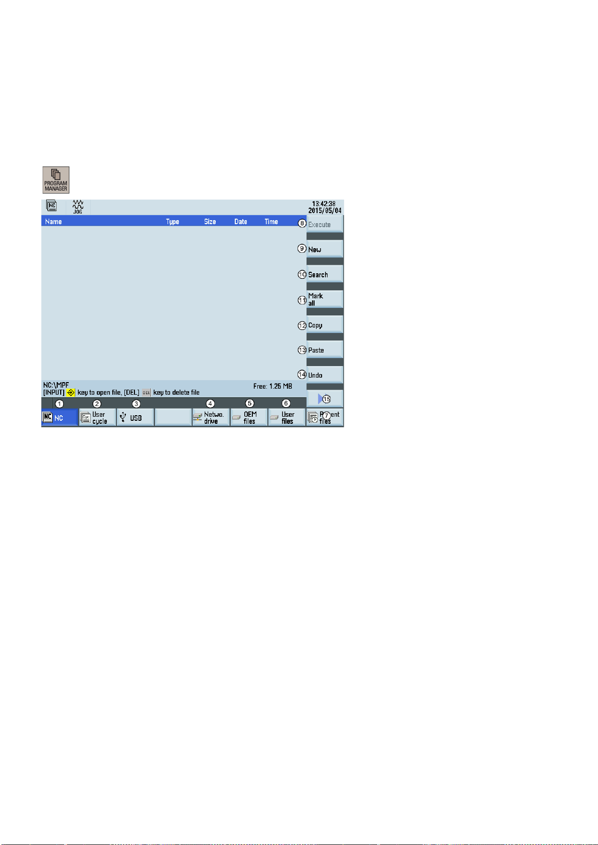
The control system can store a maximum of 300 part programs which include those created by the control system for certain
functions such as MM+, TSM, and so on.
Pressing this key on the PPU allows you to open the following window:
Stores the NC programs for subsequent operations
①
Manages and transfers the manufacturer cycles
②
Reads in/out files via the USB drive and executes the program from the external storage media
③
Reads in/out files via the Ethernet interface and executes the program from an external PC
④
Backs up manufacturer files
⑤
Backs up user files
⑥
Shows the recently accessed files
⑦
Executes the selected file. No editing is allowed in the execution process.
⑧
Creates new files or directories
⑨
Searches for files
⑩
Selects all files for the subsequent operations
⑪
Copies the selected file(s) to the clipboard
⑫
Pastes the selected file(s) from the clipboard to the current directory
⑬
Restores the deleted file(s)
⑭
Opens the lower-level menu for more options:
⑮
• Rename the part programs
• Cut the part programs
Note: Softkeys
Programming and Operating Manual (Turning)
30 6FC5398-5DP10-0BA2, 06/2015
② and ⑤ are visible only with the manufacturer password.

5.1
Creating a part program
Operating sequence
If you desire to directly create a new program file, press this softkey and proceed directly to
sary to enter the file extension ".MPF". If you desire to create a subprogram, you must enter
5.2
Editing part programs
Overview
Operating sequence
B. Enter a desired name for the new directory.
1. Select the desired operating area.
2. Enter the folder for the new program to be created.
3.
Step 4.
If you desire to create a new program directory first, press this softkey and proceed as follows before you go to Step 4:
A. Press this softkey to activate the window for creating a new directory.
C. Press this softkey to confirm your entry.
D. Select the new directory with the cursor keys.
E. Press this key on the PPU to open the directory.
4. Press this softkey to activate the window for creating a new program.
5. Enter the name of the new program. If you desire to create a main program, it is unneces-
the file extension ".SPF". The character length of a program name is limited to 24 English
characters or 12 Chinese characters. It is recommended that you do not use any special
characters in the program name.
6. Press this softkey to confirm your entry. The part program editor window opens. Enter the
blocks in the window, which are saved automatically.
A part program or sections of a part program can only be edited if currently not being executed. Any modifications to the part
program are stored immediately.
1. Select the desired operating area.
2. Enter the program directory.
Programming and Operating Manual (Turning)
6FC5398-5DP10-0BA2, 06/2015
31

e extension ".MPF" or ".SPF" must be entered if you desire to search for a program
Renumbering blocks
Searching for blocks
3. Select the program file you desire to edit. You can also search for a file or directory by either:
• Pressing this softkey and specifying the desired criteria in the search dialog. Note that
the fil
file. Or,
• Entering the first character on the main screen of the program directory. The system
directly navigates to the first file starting with that character.
window.
See below for the detailed description of the editing options.
switches to the "AUTO" mode in the machining area.
4. Press this key to open the program file. The system switches over to the program editor
5. Edit the blocks in the window as required. Any program changes are automatically stored.
6. After finishing the editing, you can press this softkey to execute the program. The system
With this softkey, the system automatically assigns block numbers to each block. The block numbers are inserted in front of each block in the ascending order in a step of 10.
Proceed through the following steps to search for a block:
1. Press this softkey in the opened program editor window.
2. Press this softkey to search via text.
Alternatively, you can search with a given line number by pressing this softkey.
3. Enter the search text or line number in the input field. Press this key to select a starting
point for search if you choose to search via text.
4. Press this softkey to start the search.
Pressing this softkey cancels the search.
Programming and Operating Manual (Turning)
32 6FC5398-5DP10-0BA2, 06/2015

Copying, cutting, and pasting blocks
5.3
Managing part programs
Searching for programs
Note:
Proceed through the following steps to copy, cut, and paste blocks:
1. Press this softkey in the opened program editor window to insert a marker.
2 Use the cursor keys to select the desired program blocks.
3. Press the corresponding softkey/key to copy/cut the selection to the buffer memory.
4. Place the cursor on the desired insertion point in the program and press this softkey.
1. Select the desired operating area.
2. Select the storage medium in which you wish to perform the search.
The following two folders are visible only with the manufacturer password:
3. Press this vertical softkey to open the search window.
4. Enter the complete name with extension of the program file to be searched in the first input
field in the search window. To narrow your search, you can enter the desired text in the
second field.
5. Use this key to choose whether to include subordinate folders or observe upper/lower case.
Programming and Operating Manual (Turning)
6FC5398-5DP10-0BA2, 06/2015
33

Copying, cutting, and pasting programs
Deleting/restoring programs
6. Press this softkey to start the search.
Pressing this softkey cancels the search.
1. Select the desired operating area.
2. Open the desired directory.
3. Select the program file that you would like to copy.
4. Perform either of the following operations as desired:
• Press this softkey to copy the selected file or directory:
5. Select the target directory with the horizontal softkeys.
2. Open the desired directory.
• Press the following softkeys to cut the selected file to the buffer memory:
→
6. Press this softkey to paste the file or directory from the clipboard to the current directory.
1. Select the desired operating area.
3. Select the program file that you would like to delete.
4. Press this key, and the following message appears on the screen:
5. Press this softkey to confirm the deletion.
Pressing this softkey cancels the operation.
Programming and Operating Manual (Turning)
34 6FC5398-5DP10-0BA2, 06/2015

Renaming programs
Viewing and executing recent programs
If you want to restore the last deleted file, press this softkey.
1. Select the desired operating area.
2. Open the desired directory.
3. Select the program file that you would like to rename.
4. Press the extension softkey to access more options.
5. Press this vertical softkey to open the window for renaming.
6. Enter a desired new name with the extension in the input field.
7. Press this softkey to confirm your entry.
Pressing this softkey cancels the operation.
1. Select the desired operating area.
2. Press this softkey to open the list of recent files. Note that even the deleted files are also
displayed in the list.
3. Select the program file that you would like to execute.
4. Press this vertical softkey to start executing the selected program.
To clear the current file list, press this softkey.
Programming and Operating Manual (Turning)
6FC5398-5DP10-0BA2, 06/2015
35

6
Automatic machining
Overview
Softkey functions
ue
The machine must have been set up for "AUTO" mode according to the specifications of the machine manufacturer. You can
perform such operations as program start, stop, control, block search, and real-time simulation, etc.
Switch to "AUTO" mode by pressing these keys.
→
Zooms in the actual value window
①
Performs the program test, dry run, conditional stop,
②
block skipping, and auxiliary function lock
Finds the desired block location
③
Corrects a wrong program block. Any changes will be
④
stored immediately.
Activates the simulation function
⑤
Sets the frequently used setting data
⑥
An extended horizontal softkey bar can be accessed via this key on the PPU. The following extended
horizontal softkey is provided:
Assigns and activates the handwheel or contour handwheel. For more information, refer to Section "Assigning the handwheel (Page 21)" and Appendix
"Activating the contour handwheel via the NC program (Page 205)".
Displays important G functions
⑦
Displays currently active auxiliary and M functions
⑧
Displays the axis feedrate in the selected coordinate
⑨
system
Displays the information of part machining time (part
⑩
timer) and part counter
Switches over the coordinate system in the actual val
⑪
window
Programming and Operating Manual (Turning)
36 6FC5398-5DP10-0BA2, 06/2015

Parameters
tive
Displays seven subsequent blocks of the currently active part program. The display of one block is limited to the width
6.1
Simulating machining
Functionality
6.1.1
Simulation prior to machining of the workpiece
Functionality
Operating sequence
Displays the axes that exist in the machine coordinate system (MCS), workpiece coordinate system (WCS), or rela
①
coordinate system (REL).
Displays the current position of the axes in the selected coordinate system.
②
Displays the remaining distance for the axes to traverse.
③
④
of the window.
By using the broken-line graphics, the programmed tool path can be traced. Before the automatic machining, you need to
perform the simulation to check whether the tool moves in the right way.
The following three variants of graphical display are available:
● Simulation prior to machining of the workpiece (Page 37)
● Simultaneous recording prior to machining of the workpiece (Page 39)
● Simultaneous recording during machining of the workpiece (Page 39)
By using the broken-line graphics, the programmed tool path can be traced. Before the automatic machining, you need to
perform the simulation to check whether the tool moves in the right way.
1. Select the desired operating area.
2. Select a part program for simulation.
3. Press this key to open the program.
Programming and Operating Manual (Turning)
6FC5398-5DP10-0BA2, 06/2015
37
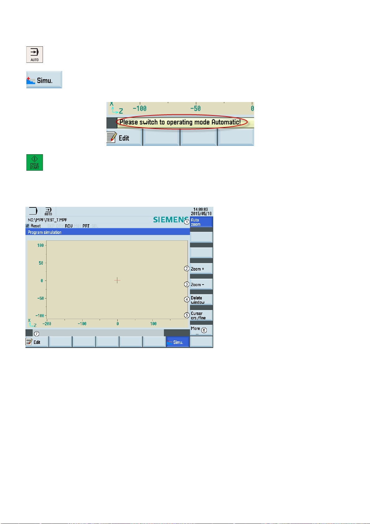
Softkey functions
4. Switch to "AUTO" mode.
5. Press this softkey to open the program simulation window, and the program control mode
PRT is automatically activated.
The following describes the functions of the softkeys on the simulation main screen.
If the control system is not in the correct operating mode, a message will appear at the
bottom of the screen as follows. If this message appears, repeat Step 4.
6. Press this key to start the standard simulation for the execution of the selected part program. Note that the simulation function can be executed only when the control system is in
"AUTO" operating mode.
Shows the simulation track automatically
①
Zooms in the whole screen
②
Zooms out the whole screen
③
Deletes the current simulation track
④
Makes the cursor move in large or small steps
⑤
Opens the lower-level menu for more simulation options:
⑥
• Enables the material removal simulation of a defined blank
• Selects whether to show the blocks or not
Returns to the program editor window
⑦
Programming and Operating Manual (Turning)
38 6FC5398-5DP10-0BA2, 06/2015

6.1.2
Simultaneous recording prior to machining of the workpiece
Operating sequence
y and the system automatically changes to "AUTO" mode in the machining
he
6.1.3
Simultaneous recording during machining of the workpiece
Operating sequence
Before machining the workpiece on the machine, you can graphically display the execution of the program on the screen to
monitor the result of the programming.
1. Select the desired operating area.
2. Select a part program for simulation.
3. Press this softke
operating area.
4. Press this softkey to open the lower-level menu for program control.
5. Press these softkeys respectively to activate the PRT mode and the feedrate settings for t
dry run.
6. Press this softkey to open the simultaneous recording window.
7. Press this key to start the recording. The program execution is displayed graphically on the
screen.
For more information about the softkeys in the simultaneous recording window, see Section "Simulation prior to machining of
the workpiece (Page 37)".
You can follow machining of the workpiece on the screen while the program is being executed on the machine. If the view of
the work space is blocked by coolant, for example, while the workpiece is being machined, you can also track the program
execution on the screen.
1. Select the desired operating area.
2. Select a part program for simulation.
3. Press this softkey and the system automatically changes to "AUTO" mode in the machining
operating area.
4. Press this softkey to open the simultaneous recording window.
Programming and Operating Manual (Turning)
6FC5398-5DP10-0BA2, 06/2015
39

6.2
Program control
Operating sequence
Softkey functions
5. Press this key to start the recording. The machining of the workpiece is started and graphically displayed on the screen.
4. Press the corresponding vertical softkey to activate or deactivate the desired program con-
1. Select the desired operating area.
2. Switch to "AUTO" mode.
3. Press this softkey to open the lower-level menu for program control.
trol option (see table below for detailed softkey functions). The softkeys selected are highlighted in blue.
Disables the output of setpoints to axes and spindles. The setpoint display "simulates" the traverse
movements.
After activating this option, the icon "PRT" appears immediately in the program status bar and this
After activating this option, the icon "M01" appears immediately in the program status bar and this
It functions the same as pressing the following key:
softkey is highlighted in blue.
For more information of the program test, refer to Section "Program test (Page 41)".
All traversing motions are performed with the feedrate setpoint specified via the "Dry run feed"
setting data. Instead of the programmed motion commands, the dry run feed rate is effective.
After activating this option, the icon "DRY" appears immediately in the program status bar and this
softkey is highlighted in blue.
Stops processing of the program at every block in which miscellaneous function M01 is pro-
grammed.
It functions the same as pressing the following key:
softkey is highlighted in blue.
Skips program blocks that are identified with a slash in front of the block number (e.g. "/N100").
After activating this option, the icon "SKP" appears immediately in the program status bar and this
softkey is highlighted in blue.
Available only in the following state:
Programming and Operating Manual (Turning)
40 6FC5398-5DP10-0BA2, 06/2015

6.3
Program test
Testing the program with dry run
Each block is decoded separately, and a stop is performed at each block. However, for the thread
blocks without dry run feedrate, a stop is only performed at the end of the current thread block.
It functions the same as pressing the following key:
After activating this option, the icon "SBL" appears immediately in the program status bar and this
softkey is highlighted in blue.
The feedrate override switch also acts on the rapid traverse override.
After activating this option, the icon "ROV" appears immediately in the program status bar and this
It functions the same as pressing the following key:
softkey is highlighted in blue.
Performs program test before real machining by checking the axis movement on the machine. It
disables the output of setpoints to spindles and suppresses all auxiliary functions.
After activating this option, the icon "AFL" appears immediately in the program status bar and this
softkey is highlighted in blue.
Note that the display is toggled between "AFL" and "PRT" by pressing the corresponding softkey.
Only one of these two functions can be active at the same time.
You can test a part program using three different methods before machining pieces.
With dry run, all programmed motion commands are replaced by a defined dry run feedrate (refer to Section "Setting the
JOG data (Page 204)"). Before executing the dry run, first remove the workpiece from the machine.
Proceed as follows to test a part program with dry run.
6. Make sure the feedrate override is 0%. Check that correct tool is in spindle before continu-
1. Select the desired operating area.
2. Switch to "AUTO" mode.
3. Press this softkey to open the lower-level menu for program control.
4. Press this vertical softkey to activate the feedrate settings for the dry run.
5. Press this key on the MCP to close the door in the machine (if you do not use this function,
just close the door in the machine manually).
ing.
7. Press this key on the MCP to run the program.
Programming and Operating Manual (Turning)
6FC5398-5DP10-0BA2, 06/2015
41

Testing the program with PRT
Press this key on the MCP to run the program. The setpoint display "simulates" the traverse
Testing the program with AFL
Auxiliary function
Address
8. Turn the feedrate override switch slowly to the desired value.
9. Press this key to stop the program test.
In PRT mode, you can simply check the correctness of your part program with no axis or spindle movement.
Proceed as follows to test a part program in PRT mode.
1. Select the desired operating area.
2. Switch to "AUTO" mode.
3. Press this key on the MCP to activate the PRT mode.
Alternatively, you can also activate PRT through the following softkey operations:
→
4.
movements.
5. Press this key to stop the program test.
The AFL (auxiliary function lock) function disables the spindle and suppresses all auxiliary functions.
Tool selection T
Tool offset D, DL
Feedrate F
Spindle speed S
M functions M
H functions H
When the AFL is active, you can test the part program by checking the axis movement. Only one of the functions PRT and
AFL can be active at the same time. Before starting the program test, first remove the workpiece from the machine.
Proceed as follows to test a part program in AFL mode.
1. Select the desired operating area.
2. Switch to "AUTO" mode.
3. Press this softkey to open the lower-level menu for program control.
Programming and Operating Manual (Turning)
42 6FC5398-5DP10-0BA2, 06/2015

6.4
Starting and stopping/interrupting a part program
Starting a part program
Operating sequence
If desired, you can use this softkey to specify how you want the program to be executed (for
Stopping/interrupting a part program
4. Press this vertical softkey to activate the AFL function.
5. Press this key on the MCP to close the door in the machine (if you do not use this function,
just close the door in the machine manually). Make sure the feedrate override is 0%.
6. Press this key on the MCP to run the program.
7. Turn the feedrate override switch slowly to the desired value.
8. Press this key to stop the program test.
Before starting a program, make sure that both the control system and the machine are set up. Observe the relevant safety
notes of the machine manufacturer.
1. Select the desired operating area.
2. Press a horizontal softkey to go to the desired directory.
3. Select the program that you desire to start.
4. Place the cursor bar on the desired program and press this softkey.
The system automatically changes to "AUTO" mode in the machining operating area after
For some directories, press the following softkey instead:
the key press.
5.
more information of the program control, refer to Section "Program control (Page 40)").
6. Press this key to start the automatic machining of the program.
Press this key to stop the execution of a part program. The program currently running is aborted.
On the next program start, the machining starts from the beginning.
Press this key to interrupt the execution of a part program. The axes stop running while the spindle
continues running. On the next program start, the machining is resumed from the interruption point.
Programming and Operating Manual (Turning)
6FC5398-5DP10-0BA2, 06/2015
43

6.5
Executing/transferring a part program through the Ethernet connection
6.5.1
Configuring the network drive
Establishing a direct connection
Establishing a network connection
A connected network drive allows you to access a shared directory on your PC from the control system. The network drive
functions based on the Ethernet connection between the control system and a PC. The following Ethernet connections are
possible:
● Direct connection: direct connection between the control system and PC.
● Network connection: integrating the control system into an existing Ethernet network.
Proceed as follows to establish a direct connection:
1. Connect the control system with the PC using an Ethernet cable.
4. Enter the main screen of the service control options through the following softkey opera-
2. Select the desired operating area on the PPU.
+
3. Press this key to view the extended softkeys.
tions:
→
5. Press this softkey to set up a direct connection between the control system and the PC.
The following dialog pops up on the screen:
Proceed as follows to establish a network connection:
1. Connect the control system with the local network using an Ethernet cable.
+
4. Enter the main screen of the service control options through the following softkey opera-
2. Select the desired operating area on the PPU.
3. Press this key to view the extended softkeys.
tions:
→
5. Press this softkey to enter the window for the network configuration.
Programming and Operating Manual (Turning)
44 6FC5398-5DP10-0BA2, 06/2015

Note:
Note: if you select "No" for DHCP, you must enter the IP address (which must belong to the
Creating and connecting a network drive
6. Configure the network as required in the following window:
You can configure the DHCP with this key.
7. Press this softkey to save the configuration. If you select "Yes" for DHCP, you also need to
make sure this vertical softkey is not selected.
same network as that of your PC) and subnet mask manually.
restart the control system to activate the network configuration.
Proceed as follows to create and connect a network drive:
1. Share a directory on your local disk on your PC.
2. Select the desired operating area on the PPU.
3. Press this softkey to go to the network drive directory.
4. Press this softkey to go to the window for configuring the network drives.
5. Press this key to select a drive identifier: N1, N2, or N3.
Programming and Operating Manual (Turning)
6FC5398-5DP10-0BA2, 06/2015
45

Note
he
6.5.2
Executing from external (through Ethernet connection)
Prerequisites:
6. Move the cursor to the following input fields:
①: Enter the user name of your Windows account
②: Enter the logon password (case sensitive) of your Windows account
③: Enter the IP address of the server and the share name of the shared directory on your
PC. Example: //140.231.196.90/808D
7. Press this softkey to confirm and the configured network drive appears on the screen as
follows. The drive icon is yellow if the network drive is connected successfully; otherwise,
After you properly configure all the settings for the direct connection between the control system and the network drive, if t
network drive connection is still invalid, contact your Windows system administrator for possible problems with your
operating system configuration.
● An Ethernet connection has been established between the control system and the PC.
● A network drive (which includes the part program to be executed) has been created and connected.
Proceed as follows to execute a part program from external through the Ethernet connection:
the icon is gray.
You can delete a selected network drive using this softkey.
1. Select the desired operating area on the PPU.
2. Press this softkey to view the network drive(s) created.
3. Enter the desired network drive (which includes the part program to be executed) with this
key.
4. Select the program file you desire to execute.
Programming and Operating Manual (Turning)
46 6FC5398-5DP10-0BA2, 06/2015

Press this softkey and the system automatically switches to "AUTO" mode in the machining
6.5.3
Transferring from external (through Ethernet connection)
Prerequisites:
Enter the desired network drive (which includes the part program to be transferred) with this
5.
operating area. The program is transferred to the buffer memory on the control system and
then displayed in the following window:
6. If desired, you can use this softkey to specify how you want the program to be executed.
For more information of the program control, refer to Section "Program control (Page 40)".
7. Press this key to execute the program. The program is reloaded continuously.
Either at the end of the program or after pressing this key, the program is automatically
removed from the control system.
● An Ethernet connection has been established between the control system and the PC.
● A network drive (which includes the part program to be transferred) has been created and connected.
Proceed as follows to transfer a part program from external through the Ethernet connection:
1. Select the desired operating area on the PPU.
2. Press this softkey to view the network drive(s) created.
3.
key.
4. Select the program file you desire to transfer.
5. Press this softkey to copy the file to the buffer memory on the control system.
6. Enter the program directory.
Programming and Operating Manual (Turning)
6FC5398-5DP10-0BA2, 06/2015
7. Press this softkey to paste the copied file into the program directory.
47

6.6
Machining at a specific point
Functionality
Operating sequence
If the part program is stopped/interrupted in the last machining operation, you can press this
The block search function provides advance of the program to the required block in the part program. You can start
machining from a specified program block after stopping/interrupting the program execution or during remachining.
1. Select the desired operating area.
2. Switch to "AUTO" mode.
3. Press this softkey to open the block search window.
4. Search for the required starting point with cursor keys or the following softkey:
softkey to load the interruption point as required.
5. Press one of the following softkeys to set the condition for the block search:
After the block search, the program will continue from the line before the interruption point.
The same calculations of the basic conditions (for example: tool and cutting edge numbers,
6. Make sure the feedrate override is 0%. Check that correct tool is in spindle before continu-
9. Turn the feedrate override switch on the MCP slowly to the desired value.
M functions, feedrate and spindle speed) are carried out as during normal program operation, but the axes do not move.
After the block search, the program will continue from the line with the interruption point.
The same calculations of the basic conditions are carried out as during normal program
operation, but the axes do not move.
Block search without calculation of the basic conditions.
ing.
7. Press this key on the MCP, and then an alarm 010208 appears for your confirmation
whether to continue.
8. Press this key again to execute the program.
Programming and Operating Manual (Turning)
48 6FC5398-5DP10-0BA2, 06/2015

7
Data backup
7.1
Internal data backup
Note
Backing up data internally
Prerequisite:
Loading internally backed up data
Method 1:
Method 2:
You can save the NC and PLC data of the volatile memory to the permanent memory of the control system. This backup is
performed internally and is always necessary if you need to switch off the control system for longer than 60 hours.
After changing important data, it is recommended to carry out an internal data backup immediately.
● A valid system password has been set on the control system.
● There is no program currently executing.
Proceed through the following steps to save data:
1. Select the desired operating area.
+
2. Open the window for data saving.
3. Press this softkey to start saving. Do not carry out any operator actions while the data backup is running.
There are two methods to load the saved data.
2. Select "Reload saved user data" in the setup menu.
1. Press this key while the control system is booting.
3. Press this key to confirm.
1. Select the desired operating area.
+
2. Open the window for selecting the startup modes.
3. Select this softkey.
Programming and Operating Manual (Turning)
6FC5398-5DP10-0BA2, 06/2015
49

Note
7.2
External data backup
7.2.1
External data backup in a data archive
Backing up data externally in a data archive
①
②
③
card)
4. Use the cursor keys to select the third startup mode as follows:
5. Press this softkey to confirm. The control system restarts with the saved data.
The following message is displayed on the screen after the control system starts up successfully with the saved data:
You must enter the password again after you have powered up the control system with the saved data.
You can perform a complete data backup of the control system by creating a startup archive.
1. Select the desired operating area.
+
2. Press this softkey to open the window for creating or restoring a startup archive.
3.
There are three options for creating a data archive. Note that options ① and ③ are visible
only with the manufacturer password.
Creates a data archive for series machine commissioning
Creates a data archive for a complete system backup
Backs up the complete system data directly on the system CompactFlash Card (CF
Select option
name for it.
② and press this softkey to confirm.
The name of the data archive is "arc_startup.arc" by default. You can use your favorite
Programming and Operating Manual (Turning)
50 6FC5398-5DP10-0BA2, 06/2015

Note
Pressing <CTRL + S> when you are in any operating area of the PPU161.3 creates a startup archive on the connected USB
Restoring a startup archive
4. Select your desired folder and press this key to open it.
5. Press this softkey to confirm and the archive information dialog opens.
6. Specify the properties of the archive and press this softkey. The control system starts creation of the startup archive.
Do not remove the USB stick in the process of data backup if you choose USB as the target directory.
stick. In addition, it automatically saves the action log to the USB stick.
1. Select the desired operating area.
+
2. Press this softkey to open the startup archive window.
3. Select the following option and press this softkey to restore the startup archive:
4. Select the backup path to locate the archive file and press this softkey to confirm.
5. Press this softkey to confirm the archive information.
6. Press this softkey to continue and start restoring the startup archive. The control system
restarts to complete restoring the archive.
Programming and Operating Manual (Turning)
6FC5398-5DP10-0BA2, 06/2015
51

7.2.2
External data backup of separate files
Operating sequence
In the program management operating area, program files or directories can be copied into another directory or onto a
different drive by means of copying and pasting operations.
1. Select the desired operating area.
2. Enter the program directory.
3. Select the program file or directory to be backed up. You can alternatively use the following
softkey to search for the desired file or directory:
4. Press this softkey to copy the data to the clipboard.
5. Select a desired directory or drive as the data target.
Backs up the files in the folder for storing the user cycles on the control system. This folder
is visible with the manufacturer password.
Backs up the files onto an USB stick.
Backs up the files onto an external PC. This requires a connected network drive on the
control system. For more information, see section "Configuring the network drive
For more information about data backup, refer to the SINUMERIK 808D ADVANCED Diagnostics Manual.
(Page 44)".
Backs up the files in the folder for storing the manufacturer files on the control system. This
folder is visible with the manufacturer password.
Backs up the files in the folder for storing end user files on the control system.
6. Press this softkey to paste the copied data into the current directory.
Programming and Operating Manual (Turning)
52 6FC5398-5DP10-0BA2, 06/2015

8
Programming principles
8.1
Fundamentals of programming
8.1.1
Program names
Example
8.1.2
Program structure
Structure and content
blocks
words
Block
Word
Word
Word
...
; Comment
8.2
Positional data
8.2.1
Programming dimensions
Note
The real purpose of this and the following sections is to illustrate the conventional structure
Each program must have a program name. The program name must follow the conventions below:
● Use a maximum of 24 letters or 12 Chinese characters for a program name (the character length of the file extension
excluded)
● Separate the file extension only with a decimal point
● Enter the file extension ".SPF" if the current default program type is MPF (main program) and you desire to create a
subprogram
● Enter the file extension ".MPF" if the current default program type is SPF (subprogram) and you desire to create a main
program
● Do not enter the file extension if you desire to take the current default program type
● Avoid using special characters for program names.
WORKPIECE527
The NC program consists of a sequence of
Instructions are written in the blocks in the form of
for the end of the program,
The following table shows you an example of the NC program structure.
Block N10 G0 X20 ... ; First block
Block N20 G2 Z37 ... ; Second block
Block N30 G91 ... ... ; ...
Block N40 ... ... ...
Block N50 M2 ; End of program
In this section you will find descriptions of the commands, with which you can directly program dimensions taken from a
drawing. This has the advantage that no extensive calculations have to be made for NC programming.
for example, M2.
(see the table below). Each block represents a machining step.
. The last block in the execution sequence contains a special word
The commands described in this section stand in most cases at the start of a NC program. The way, in which these
functions are combined, is not intended to be a patent remedy. For example, the choice of working plane may be made at
another point in the NC program.
of an NC program.
Programming and Operating Manual (Turning)
6FC5398-5DP10-0BA2, 06/2015
53

Overview of typical dimensions
8.2.2
Absolute/incremental dimensioning: G90, G91, AC, IC
Functionality
not determine the path
Programming
G90
; Absolute dimension data
G91
; Incremental dimension data
Z=AC(...)
; Absolute dimensioning for a certain axis (here: Z axis), non-modal
Z=IC(...)
; Incremental dimensioning for a certain axis (here: Z axis), non-modal
The basis of most NC programs is a drawing with concrete dimensions.
When implementing in a NC program, it is helpful to take over exactly the dimensions of a workpiece drawing into the
machining program. These can be:
● Absolute dimension, G90 modally effective applies for all axes in the block, up to revocation by G91 in a following block.
● Absolute dimension, X=AC(value) only this value applies only for the stated axis and is not influenced by G90/G91. This
is possible for all axes and also for SPOS, SPOSA spindle positionings, and interpolation parameters I, J, K.
● Absolute dimension, X=DC(value) directly approaching the position by the shortest route, only this value applies only for
the stated rotary axis and is not influenced by G90/G91. This is also possible for SPOS, SPOSA spindle positionings.
● Absolute dimension, X=ACP(value) approaching the position in positive direction, only this value is set only for the rotary
axis, the range of which is set to 0... < 360 degrees in the machine data.
● Absolute dimension, X=ACN(value) approaching the position in negative direction, only this value is set only for the
rotary axis, the range of which is set to 0... < 360 degrees in the machine data.
● Incremental dimension, G91 modally effective applies for all axes in the block, until it is revoked by G90 in a following
block.
● Incremental dimension, X=IC(value) only this value applies exclusively for the stated axis and is not influenced by
G90/G91. This is possible for all axes and also for SPOS, SPOSA spindle positionings, and interpolation parameters I, J,
K.
● Inch dimension, G70 applies for all linear axes in the block, until revoked by G71 in a following block.
● Metric dimension, G71 applies for all linear axes in the block, until revoked by G70 in a following block.
● Inch dimension as G70, however, G700 applies also for feedrate and length-related setting data.
● Metric dimension as G71, however, G710 applies also for feedrate and length-related setting data.
● Diameter programming, DIAMON on
● Diameter programming, DIAMOF off
Diameter programming, DIAM90 for traversing blocks with G90. Radius programming for traversing blocks with G91.
With the instructions G90/G91, the written positional data X, Z, ... are evaluated as a coordinate point (G90) or as an axis
position to traverse to (G91). G90/91 applies for all axes.
Irrespective of G90/G91, certain positional data can be specified for certain blocks in absolute/incremental dimensions using
AC/IC.
These instructions do
G2 and G3...). For more information, see Sections "Linear interpolation (Page 69)" and "Circular interpolation (Page 71)".
See the following different dimensioning types in the drawing:
by which the end points are reached; this is provided by a G group (G0, G1,
Programming and Operating Manual (Turning)
54 6FC5398-5DP10-0BA2, 06/2015

Absolute dimensioning G90
zero of the coordinate system currently active
all axes
Incremental dimensioning G91
axis path to be traversed
traversing direction
Specification with =AC(...), =IC(...)
Programming example
N10 G90 X20 Z90
; Absolute dimensions
N20 X75 Z=IC(-32)
; X-dimensions remain absolute, incremental Z dimension
N180 G91 X40 Z2
; Switch-over to incremental dimensioning
N190 X-12 Z=AC(17)
; X-remains incremental dimensioning, Z-absolute
8.2.3
Dimensions in metric units and inches: G71, G70, G710, G700
Functionality
Programming
Programming example
N10 G70 X10 Z30
; Inch dimensions
N20 X40 Z50
;G70 continues to act
N80 G71 X19 Z17.3
; metric dimensioning from this point on
Information
default setting
or
metric default setting.
workpiece
Programmable
settable
G70/G71
G700/G710,
With absolute dimensioning, the dimensioning data refers to the
or current workpiece coordinate system or machine coordinate system). This is dependent on which offsets are currently
active: programmable, settable, or no offsets.
Upon program start, G90 is active for
and remains active until it is deselected in a subsequent block by G91
(incremental dimensioning data) (modally active).
With incremental dimensioning, the numerical value of the path information corresponds to the
The leading sign indicates the
.
G91 applies to all axes and can be deselected in a subsequent block by G90 (absolute dimensioning).
After the end point coordinate, write an equality sign. The value must be put in round brackets.
Absolute dimensioning is also possible for center points using =AC(...). Otherwise, the reference point for the circle center is
the circle starting point.
(workpiece
.
If workpiece dimensions that deviate from the base system settings of the control system are present (inch or mm), the
dimensions can be entered directly in the program. The required conversion into the base system is performed by the control
system.
G70 ; Inch dimensions
G71 ; Metric dimensions
G700 ; Inch dimensions, also for feedrate F
G710 ; Metric dimensions, also for feedrate F
Depending on the
you have chosen, the control system interprets all geometric values as either metric
inch dimensions. Tool offsets and settable work offsets including their displays are also to be understood as geometrical
values; this also applies to the feed F in mm/min or inch/min.
The default setting can be set in machine data.
All examples provided in this manual assume the
G70 or G71 evaluates all geometrical data that directly refer to the
, either as inches or metric units, for example:
● Positional data X, Z, ... for G0,G1,G2,G3,G33, CIP, CT
● Interpolation parameters I, K (also thread lead)
● Circle radius CR
●
All remaining geometric parameters that are not direct workpiece parameters, such as feedrates, tool offsets, and
work offsets, are not affected by
work offset (TRANS, ATRANS)
.
however, also affects the feedrate F (inch/min, inch/rev. or mm/min, mm/rev.).
Programming and Operating Manual (Turning)
6FC5398-5DP10-0BA2, 06/2015
55

8.2.4
Radius/diameter dimensions: DIAMOF, DIAMON, DIAM90
Functionality
X-axis
Programming
Programming example
N10 G0 X0 Z0
;Approach starting point
N20 DIAMOF
Diameter input off
N30 G1 X30 S2000 M03 F0.8
; X-axis = traverse axis active
; traverse to radius position X30
N40 DIAMON
; Diameter dimensions active
N50 G1 X70 Z-20
; Traverse to diameter position X70 and Z-20
N60 Z-30
N70 DIAM90
; diameter programming for absolute dimension and
; radius programming for incremental dimension
N80 G91 X10 Z-20
Incremental dimension
N90 G90 X10
Absolute dimensions
N100 M30
;End of program
Note
8.2.5
Programmable work offset: TRANS, ATRANS
Functionality
For machining parts, the positional data for the
necessary, it is possible to switch to radius dimensioning in the program.
DIAMOF or DIAMON assesses the end point specification for the X axis as radius or diameter dimensioning. The actual
value appears in the display accordingly for the workpiece coordinate system.
For DIAM90, irrespective of the traversing method (G90/G91), the actual value of the transverse axis is always displayed as
a diameter. This also applies to reading of actual values in the workpiece coordinate system with MEAS, MEAW, $P_EP[x]
and $AA_IW[x].
DIAMOF ; Radius dimensioning
DIAMON ; Diameter dimensioning
DIAM90 ; diameter dimensioning for G90, radius dimensioning for G91
See the following diameter and radius dimensioning for the traverse axis:
(transverse axis) is programmed as diameter dimensioning. When
A programmable offset with TRANS X... or ATRANS X... is always evaluated as radius dimensioning. Description of this
function: see the next section.
The programmable work offset can be used:
● for recurring shapes/arrangements in various positions on the workpiece
● when selecting a new reference point for the dimensioning
● as a stock allowance when roughing
Programming and Operating Manual (Turning)
56 6FC5398-5DP10-0BA2, 06/2015
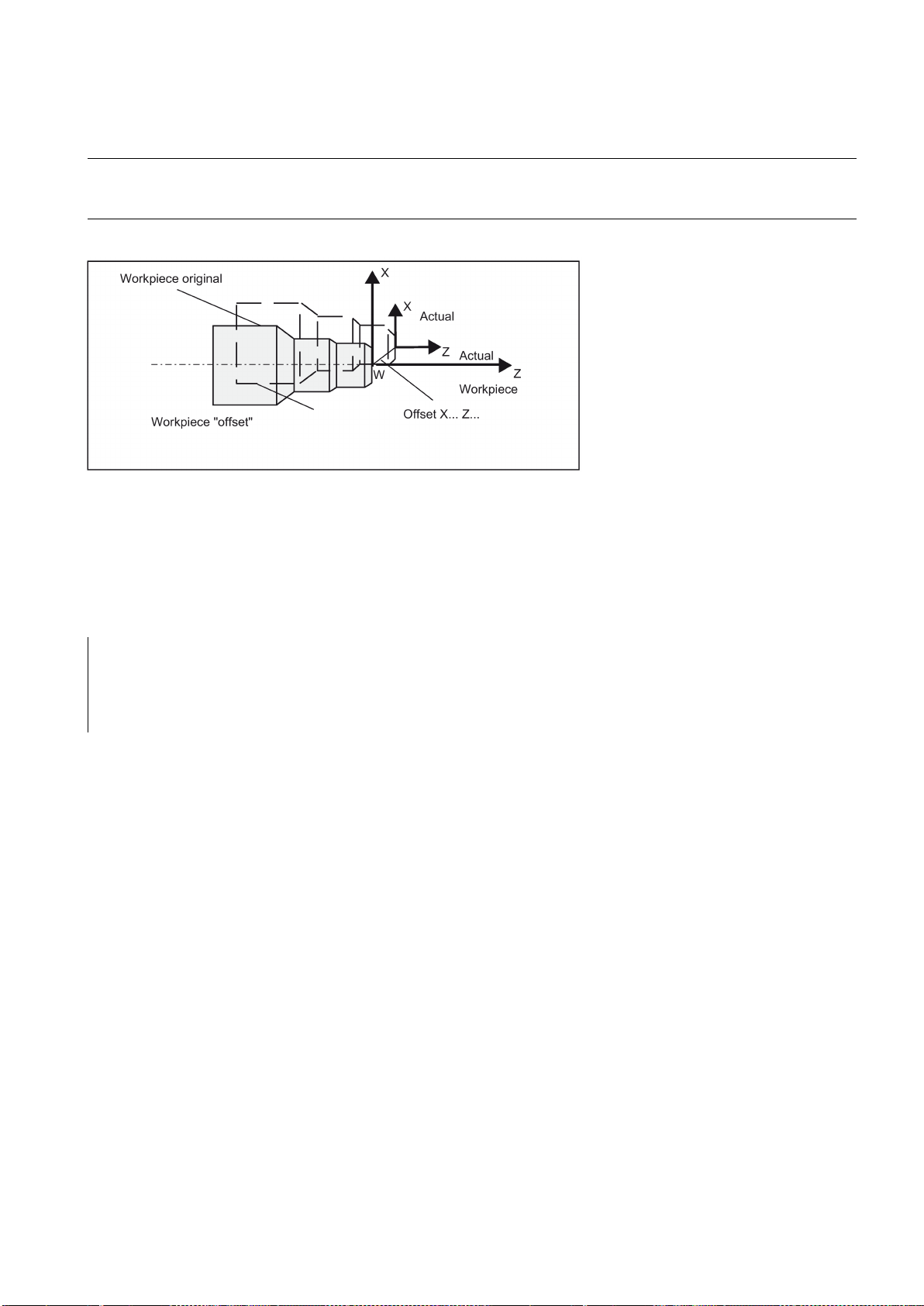
current workpiece coordinate system
Note
Programming
Programming example 1
N10 G54
N20 TRANS Z5
; programmable offset, 5 mm in Z-axis
N30 L10
; Subroutine call; contains the geometry to be offset
N40 ATRANS X10
; programmable offset, 10 mm in x-axis
N50 TRANS
; offset cleared
N60 M30
Programming example 2
This results in the
. The rewritten dimensions use this as a reference.
The offset is possible in all axes.
In the X-axis, the workpiece zero should be in the turning center due to the functions of diameter programming (DIAMON)
and constant cutting speed (G96). For this reason, use no offset or only a small offset (e.g. as allowance) in the X axis.
See the following effect of the programmable offset:
TRANS Z... ; programmable offset, deletes old instructions for offsetting, rotation, scaling factor, mirroring
ATRANS Z... ; programmable offset, additive to existing instructions
TRANS ; without values: clears old instructions for offset, rotation, scaling factor, mirroring
The instructions that contain TRANS or ATRANS each require a separate block.
Subroutine call: see Section "Subroutine technique (Page 113)".
G90 G18 G500
T3D1
M4S1500
G0X50 Z10
CYCLE95( "CON1:CON1_E", 0.50000, 0.20000, 0.20000, ,0.20000, 0.20000, 0.15000, 9, , ,2.00000)
M4S1200
G0X100Z-10
R0=46
LAB1:
TRANS X=R0 Z-25
AROT RPL=-10
R1=-45
R2=14
Programming and Operating Manual (Turning)
6FC5398-5DP10-0BA2, 06/2015
57

R3=34
LAB:
TRANS X=R0 Z-25
AROT RPL=10
R5=R2*COS(R1)
R6=R3*SIN(R1)
G1 Z=R5 X=R6
R1=R1-0.5
IF R1>=-151 GOTOB LAB
R0=R0-0.5
IF R0>=40 GOTOB LAB1
G0X80
Z50
AROT
TRANS
G500
T5D1
M4S1000
G1F0.1
CYCLE93( 58.00000, -36.00000, 22.00000, 0.90000, , , , , , , ,0.10000, 0.10000, 0.50000, 0.10000, 5, 2.00000)
G0X80
Z50
T3D1
M4S1500
R0=29
BB:
TRANS Z-52 X=R0
DIAMOF
R4=720
LL:
R1=(3.14159*R4)/180
R2=SIN(R4)
G1 X=R2 Z=R1
R4=R4-0.5
IF R4>=0 GOTOB LL
DIAMON
R0=R0-0.5
IF R0>=27 GOTOB BB
G0X80
Z50
Programming and Operating Manual (Turning)
58 6FC5398-5DP10-0BA2, 06/2015

8.2.6
Programmable scaling factor: SCALE, ASCALE
Functionality
Programming
Notes
M30
;*************CONTOUR************
CON1:
X42Z0
X54Z-13
X58
Z-60
X60
M02
CON1_E:;************* CONTOUR ENDS ************
A scale factor can be programmed for all axes with SCALE, ASCALE. The path is enlarged or reduced by this factor in the
axis specified.
The currently set coordinate system is used as the reference for the scale change.
SCALE X... Z... ; Programmable scaling factor, clears old instructions for offset, rotation, scaling factor, mir-
roring
ASCALE X... Z... ; Programmable scaling factor, additive to existing instructions
SCALE ; Without values: clears old instructions for offset, rotation, scaling factor, mirroring
The instructions that contain SCALE or ASCALE each require a separate block.
● For circles, the same factor should be used in both axes.
● If an ATRANS is programmed with SCALE/ASCALE active, these offset values are also scaled.
See the following example of a programmable scale factor:
Programming and Operating Manual (Turning)
6FC5398-5DP10-0BA2, 06/2015
59

Programming example
N10 L10
; Programmed contour original
N20 SCALE X2 Z2
; contour in X and Z enlarged 2 times
N30 L10
N40 ATRANS X2.5 Z1.8
N50 L10
N60 M30
Information
8.2.7
Workpiece clamping - settable work offset: G54 to G59, G500, G53, G153
Functionality
Programming
Programming example
Subroutine call - see Section "Subroutine technique (Page 113)".
In addition to the programmable offset and the scale factor, the following functions exist:
● Programmable rotation ROT, AROT and
● Programmable mirroring, MIRROR, AMIRROR.
These functions are primarily used in milling.
Examples of rotation and mirroring: see Section "List of instructions (Page 236)".
The adjustable work offset specifies the position of the workpiece zero on the machine (offset of the workpiece zero with
respect to the machine zero point). This offset is determined upon clamping of the workpiece into the machine and must be
entered in the corresponding data field by the operator. The value is activated by the program by selection from six possible
groupings: G54 to G59.
G54 to G59 ; 1. to 6th settable work offset
G500 ; Settable work offset OFF - modal
G53 ; settable work offset OFF non-modal, also suppresses programmable offset
G153 ; As with G53; additionally suppresses base frame
See the following illustration for settable work offset:
N10 G54 G0 X50 Z135
N20 X70 Z160
N30 T1 D1
N40 M3 S1000
N50 G0 X20 Z130
N60 G01 Z150 F0.12
Programming and Operating Manual (Turning)
60 6FC5398-5DP10-0BA2, 06/2015

8.2.8
Kinematic transformation
8.2.8.1
Milling on turned parts (TRANSMIT)
Function
TRANSMIT transformation type
Syntax
N70 X50 F0.1
N80 G500 X100 Z170
N90 M30
The TRANSMIT function enables the following:
● Face machining on turned parts in the turning clamp (drill-holes, contours).
● A cartesian coordinate system can be used to program these machining operations.
● The controller maps the programmed traversing movements of the Cartesian coordinate system onto the traversing
● A tool center offset relative to the turning center is permitted.
● The velocity control makes allowance for the limits defined for the rotations.
● In addition to the tool length compensation, it is also possible to work with the tool radius compensation (G41, G42).
movements of real machine axes (standard situation):
– Rotary axis:
The main spindle functions here as the machine rotary axis.
– Infeed axis perpendicular to rotary axis
– Longitudinal axis parallel to rotary axis
– The linear axes are positioned perpendicular to one another.
TRANSMIT in the standard case with (TRAFO_TYPE_n = 256)
TRANSMIT
TRAFOOF
Rotary axis
Programming and Operating Manual (Turning)
6FC5398-5DP10-0BA2, 06/2015
61

Meaning
Note
Example
Program code
Comment
N10 T1 D1 G54 G17 G90 F1000 G94
; Tool selection
N20 G0 X20 Z10 SPOS=45
; Approach the starting position
N30 SETMS(2)
; Set the second spindle as the main spindle
N40 M3 S2000
; Run the spindle
N50 TRANSMIT
; Activate TRANSMIT function
N60 ROT RPL=-45
; Set frame
N70 DIAMOF
N80 G1 X10 Y-10 G41 OFFN=1OFFN
; Square roughing; 1 mm tolerance
N90 X-10
N100 Y10
N110 X10
N120 Y-10
N130 G1 Z20 G40 OFFN=0
; Tool change
N140 T2 D1 X15 Y-15
N150 Z10 G41
N160 G1 X10 Y-10
; Square finishing
N170 X-10
N180 Y10
N190 X10
N200 Y-10
N210 Z20 G40
; Deselect frame
N220 TRAFOOF
N230 SETMS(1)
; Set the first spindle back
N240 G0 X20 Z10 SPOS=45
; Approach the starting position
N250 M30
The rotary axis cannot be programmed as it is occupied by a geometry axis and thus cannot be programmed directly as
channel axis.
TRANSMIT: Activates the first declared TRANSMIT function. This function is also designated as polar transformation.
TRAFOOF: Deactivates an active transformation.
OFFN: Offset contour normal: Distance of the face machining from the programmed reference contour.
An active TRANSMIT transformation is likewise deactivated if one of the other transformations is activated in the relevant
channel (e.g. TRACYL).
Programming and Operating Manual (Turning)
62 6FC5398-5DP10-0BA2, 06/2015

Description
Pole
Information
8.2.8.2
Cylinder surface transformation (TRACYL)
Functionality
There are two ways of passing through the pole:
● Traverse the linear axis alone
● Traverse to the pole, rotate the rotary axis at the pole and traveling away from the pole
Make the selection using MD 24911 and 24951.
The turning center with X0/Y0 is designated as the pole. Workpiece machining operations close to the pole are not
recommended since these may require sharp feedrate reductions to prevent overloading of the rotary axis. Avoid selecting
TRANSMIT when the tool is positioned exactly on the pole. Ensure that the path of the tool center point does not travel
through the X0/Y0 pole.
● The TRACYL cylinder surface transformation function can be used to machine:
– Longitudinal grooves on cylindrical bodies
– Transverse grooves on cylindrical objects
– Grooves with any path on cylindrical bodies
The path of the grooves is programmed with reference to the unwrapped, level surface of the cylinder.
● The control system transforms the programmed traversing movements in the Cartesian
coordinate X, Y, Z system into traversing movements of the real machine axes. The main
spindle functions here as the machine rotary axis.
● TRACYL must be configured using special machine data. The rotary axis position at
which the value Y=0 is also defined here.
● If the machine has a real machine Y-axis(YM), an expanded TRACYL variant can also be configured. This allows
grooves with groove wall offset to be produced: the groove wall and base are perpendicular to each other - even if the
milling tool's diameter is smaller than the groove width. This is otherwise only possible with exact fitting milling cutters.
Programming and Operating Manual (Turning)
6FC5398-5DP10-0BA2, 06/2015
63

TRACYL transformation types
Axis utilization
Programming
Rotary axis
Meaning
whose value for TRACYL is preselected using the mode for machine
Note
OFFN address
There are three forms of cylinder surface coordinate transformation:
● TRACYL without groove wall offset (TRAFO_TYPE_n=512)
● TRACYL with groove wall offset: (TRAFO_TYPE_n=513)
● TRACYL with additional linear axis and groove wall offset: (TRAFO_TYPE_n=514)
The groove wall offset is parameterized with TRACYL using the third parameter.
For cylinder peripheral curve transformation with groove side compensation, the axis used for compensation should be
positioned at zero (y=0), so that the groove centric to the programmed groove center line is finished.
The following axes cannot be used as a positioning axis or a reciprocating axis:
● The geometry axis in the peripheral direction of the cylinder peripheral surface (Y axis)
● The additional linear axis for groove side compensation (Z axis).
TRACYL(d) or TRACYL(d, n) or for transformation type 514
TRACYL(d, n, groove side offset)
TRAFOOF
The rotary axis cannot be programmed as it is occupied by a geometry axis and thus cannot be programmed directly as
channel axis.
TRACYL(d) Activates the first TRACYL function specified in the channel machine data.
d is the parameter for the working diameter.
TRACYL (d, n) Activates the n-th TRACYL function specified in the channel machine data.
The maximum for n is 2, TRACYL(d,1) corresponds to TRACYL(d).
D Value for the working diameter. The working diameter is double the distance between the
tool tip and the turning center. This diameter must always be specified and be larger than 1.
n Optional 2nd parameter for the TRACYL data block 1 (preselected) or 2.
Slot side compensation Optional 3rd parameter
data.
Value range:
0: Transformation type 514 without groove wall offset as previous
1: Transformation type 514 with groove wall offset
TRAFOOF Transformation OFF (BCS and MCS are once again identical).
OFFN Offset contour normal: Distance of the groove side from the programmed reference contour.
An active TRACYL transformation is likewise deactivated if one of the other transformations is activated in the relevant
channel (e.g. TRANSMIT).
Distance from the groove side wall to the programmed path.
The groove center line is generally programmed. OFFN defines the (half) groove width for activated milling cutter radius
compensation (G41, G42).
Programming: OFFN=...; distance in mm
Programming and Operating Manual (Turning)
64 6FC5398-5DP10-0BA2, 06/2015
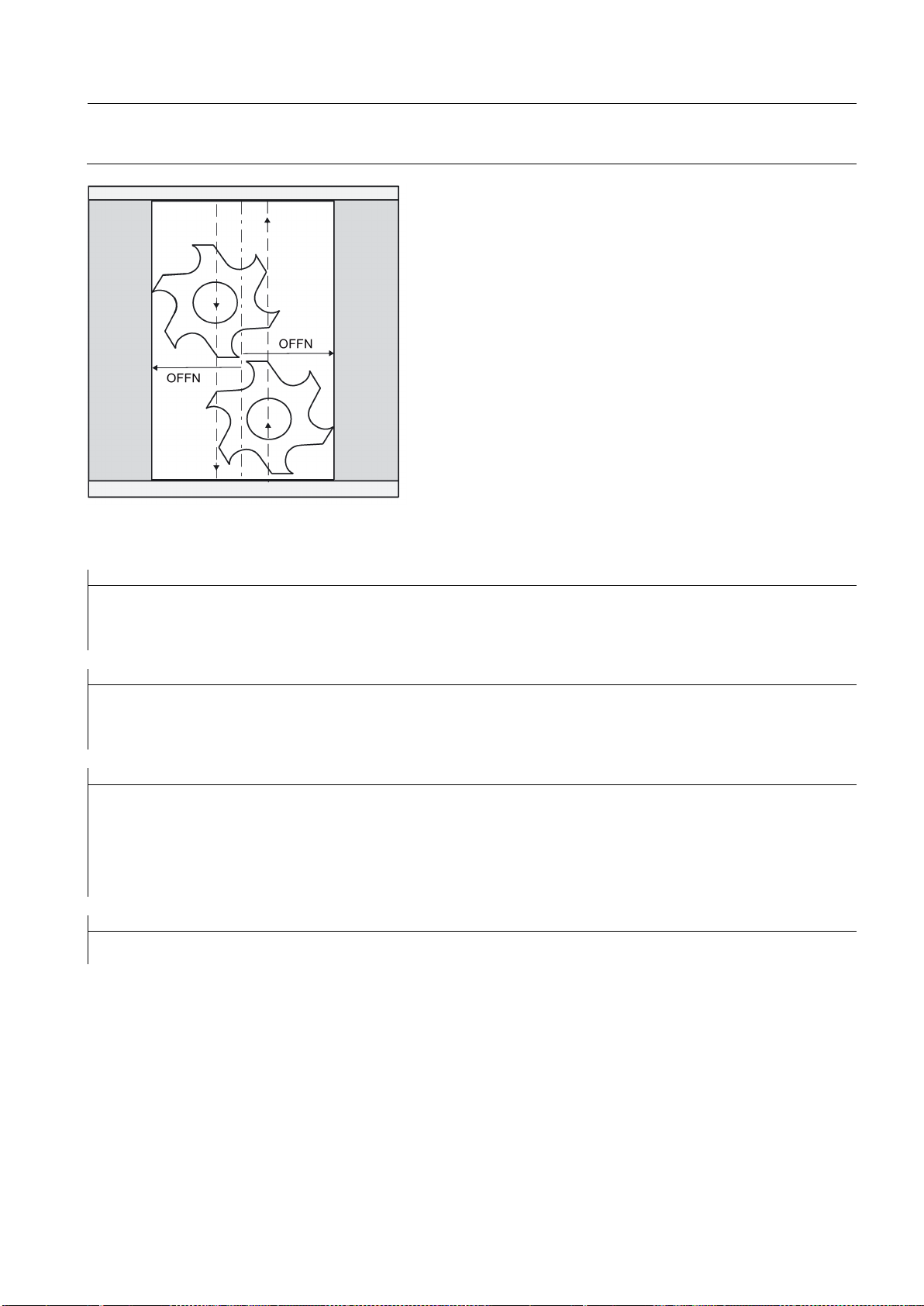
Note
Example: Tool definition
Program code
Comment
Tool parameters
Meaning
Number (DP)
$TC_DP1[1,1]=120
Tool type (Milling tool)
$TC_DP2[1,1]=0
Cutting edge position (Only for turning tools)
Program code
Comment
Geometry
Length compensation
$TC_DP3[1,1]=8.
Length offset vector (Calculation acc. to type and plane)
$TC_DP4[1,1]=9.
$TC_DP5[1,1]=7.
Program code
Comment
Geometry
Radius
$TC_DP6[1,1]=6.
Tool radius
$TC_DP7[1,1]=0
Slot width b for slotting saw, rounding radius for milling tools
$TC_DP8[1,1]=0
Projection k (For slotting saw only)
$TC_DP9[1,1]=0
$TC_DP10[1,1]=0
$TC_DP11[1,1]=0
Angle for taper milling tools
Program code
Comment
Wear
Length and radius compensation
$TC_DP12[1,1]=0
Remaining parameters to $TC_DP24=0 (Tool base dimension/adapter)
Set OFFN=0 once the groove has been completed. OFFN is also used outside of TRACYL - for offset programming in
combination with G41, G42.
The following example is suitable for testing the parameterization of the TRACYL cylinder transformation:
Programming and Operating Manual (Turning)
6FC5398-5DP10-0BA2, 06/2015
65

Example: Making a hook-shaped groove
Activate cylinder surface transformation:
Program code
Comment
N10 T1 D1 G54 G90 G94
F1000
; Tool selection, clamping compensation
N20 SPOS=0
; Approach the starting position
N30 SETMS(2)
; Set the second spindle as the main spindle
N40 M3 S2000
; Run the spindle
N50 DIAMOF
; Change the diameter dimensioning to radius dimensioning
N60 G0 X23 Z105
N70 TRACYL (20)
; Activate cylinder surface ;transformation
N80 G19
; Plane selection
Machining a hook-shaped groove:
Program code
Comment
N90 G1 Y0 Z-10
; Approach starting position
N100 G42 OFFN=-4.5
; Tool radius compensation right of contour on
N110 X19 F500
N120 Z-25
N130 Y30
N140 OFFN=-3.5
N150 Y0
N160 Z-10
N170 X25
N180 TRAFOOF
N190 DIAMON
; Diameter dimensioning
N200 G40
; Tool radius compensation off
N210 G0 X80 Z100
; Retraction in rapid traverse
N220 M30
; End of program
Description
Without groove wall offset (transformation type 512)
Required tool: T1 milling tool, radius=3 mm, edge position=8.
The controller transforms the programmed traversing movements of the cylinder coordinate system to the traversing
movements of the real machine axes:
● Rotary axis
● Infeed axis perpendicular to rotary axis
● Longitudinal axis parallel to rotary axis
Programming and Operating Manual (Turning)
66 6FC5398-5DP10-0BA2, 06/2015

With groove wall offset (transformation type 513)
Groove traversing-section
The linear axes are positioned perpendicular to one another. The infeed axis cuts the rotary axis.
Kinematics as above, but an additional longitudinal axis parallels to the peripheral direction.
The linear axes are positioned perpendicular to one another.
The velocity control makes allowance for the limits defined for the rotations.
In the case of axis configuration 1, longitudinal grooves along the rotary axis are subject to parallel limits only if the groove
width corresponds exactly to the tool radius.
Grooves in parallel to the periphery (transverse grooves) are not parallel at the beginning and end.
Programming and Operating Manual (Turning)
6FC5398-5DP10-0BA2, 06/2015
67

With additional linear axis and groove wall offset (transformation type 514)
Offset contour normal OFFN (transformation type 513)
On a machine with a second linear axis, this transformation variant makes use of redundancy in order to perform improved
tool compensation. The following conditions then
apply to the second linear axis:
● A smaller working area
● The second linear axis should not be used for traversing the part program.
Certain machine data settings are assumed for the part program and the assignment of the corresponding axes in the BCS
or MCS.
For more information, see the SINUMERIK 808D/SINUMERIK 808D ADVANCED Function Manual.
To mill grooves with TRACYL, the following is programmed:
● Groove center line in the part program
● Half the groove width programmed using OFFN.
To avoid damage to the groove side OFFN acts only when the tool radius compensation is active. Furthermore, OFFN
should also be >= the tool radius to avoid damage occurring to the opposite side of the groove.
Programming and Operating Manual (Turning)
68 6FC5398-5DP10-0BA2, 06/2015

Special features
Note
OFFN and TRC
With TRAFO_TYPE_n = 512, the value is effective under OFFN as an allowance for TRC. With TRAFO_TYPE_n = 513, half
8.3
Linear interpolation
8.3.1
Linear interpolation with rapid traverse: G0
Functionality
not for direct workpiece machining
maximum
possible path velocity
A part program for milling a groove generally comprises the following steps:
1. Selecting a tool
2. Select TRACYL
3. Select suitable coordinate offset (frame)
4. Positioning
5. Program OFFN
6. Select TRC
7. Approach block (position TRC and approach groove side)
8. Groove center line contour
9. Deselect TRC
10. Retraction block (retract TRC and move away from groove side)
11. Positioning
12. Deselect OFFN
13. TRAFOOF
14. Re-select original coordinate shift (frame)
● TRC selection:
TRC is not programmed in relation to the groove side, but relative to the programmed groove center line. To prevent the
tool traveling to the left of the groove side, G42 is entered (instead of G41). You avoid this if in OFFN, the groove width is
entered with a negative sign.
● OFFN acts differently with TRACYL than it does without TRACYL. As, even without TRACYL, OFFN is included when
TRC is active, OFFN should be reset to zero after TRAFOOF.
● It is possible to change OFFN within a part program. This could be used to shift the groove center line from the center
(see diagram).
● Guiding grooves:
TRACYL does not create the same groove for guiding grooves as it would be with a tool with the diameter producing the
width of the groove. It is basically not possible to create the same groove side geometry with a smaller cylindrical tool as
it is with a larger one. TRACYL minimizes the error. To avoid problems of accuracy, the tool radius should only be slightly
smaller than half the groove width.
the groove width is programmed in OFFN. The contour is retracted with OFFN-TRC.
The rapid traverse movement G0 is used for fast positioning of the tool, however,
All axes can be traversed simultaneously - on a straight path.
For each axis, the maximum speed (rapid traverse) is defined in machine data. If only one axis traverses, it uses its rapid
traverse. If two axes are traversed simultaneously, the path velocity (resulting velocity) is selected to achieve the
Any programmed feedrates (F word) are not relevant for G0.
G0 remains active until canceled by another instruction from this G group (G0, G1, G2, G3, ...).
Programming and Operating Manual (Turning)
6FC5398-5DP10-0BA2, 06/2015
in consideration of both axes.
.
69

Programming example
N10 G0 X100 Z65
Note
Information
8.3.2
Feedrate F
Functionality
path velocity
Programming
:
integer values
Unit of measure for F with G94, G95
mm/min
mm/rev.
Remark:
Programming example
N10 G94 F310
; Feedrate in mm/min
N20 G01 X60 Z60
N30 M5
N40 S200 M3
; Spindle rotation
N50 G95 F0.8
; Feedrate in mm/revolution
N60 G01 X100 Z100
N70 M30
See the following illustration for linear interpolation with rapid traverse from point P1to P2:
Another option for linear programming is available with the angle specification ANG=. (For more information, see Section
"Contour definition programming (Page 96)".)
Another group of G functions exists for moving into the position (see Section "Exact stop/continuous-path control mode: G9,
G60, G64 (Page 82)"). For G60 exact stop, a window with various precision values can be selected with another G group.
For exact stop, an alternative instruction with non-modal effectiveness exists: G9.
You should consider these options for adaptation to your positioning tasks.
The feed F is the
and represents the value of the geometric sum of the velocity components of all axes
involved. The axis velocities are determined from the share of the axis path in the overall path.
The feedrate F is effective for the interpolation types G1, G2, G3, CIP, and CT and is retained until a new F word is written.
For more information, see Sections "Linear interpolation with feedrate: G1 (Page 71)" and "Circular interpolation: G2, G3
(Page 71)".
F...
Remark
, the decimal point is not required, e.g.: F300
For
The dimension unit for the F word is determined by G functions:
● G94 F as feedrate in
● G95 F as feedrate in
(only relative to the spindle speed!)
This unit of measure applies to metric dimensions. According to Section "Metric and inch dimensioning", settings with inch
dimensioning are also possible.
Programming and Operating Manual (Turning)
70 6FC5398-5DP10-0BA2, 06/2015

Remark
Information
8.3.3
Linear interpolation with feedrate: G1
Functionality
path velocity,
F word
Programming example
N05 G54 G0 G90 X40 Z200 S500 M3
; The tool traverses in rapid traverse, spindle speed
= 500 r.p.m., clockwise
N10 G1 Z120 F0.15
; Linear interpolation with feedrate 0.15
mm/revolution
N15 X45 Z105
N20 Z80
N25 G0 X100
; Retraction in rapid traverse
N30 M2
; End of program
Note:
8.4
Circular interpolation
8.4.1
Circular interpolation: G2, G3
Functionality
The G group with G94, G95 also contains the functions G96, G97 for the constant cutting rate. These functions also
influence the S word.
The tool moves from the starting point to the end point along a straight path. For the
programmed
All the axes can be traversed simultaneously.
G1 remains active until canceled by another instruction from this G group (G0, G2, G3...).
See the following illustration for linear interpolation with G1:
: Write a new F word if you change G94 - G95.
.
is determined by the
Another option for linear programming is available with the angle specification ANG=.
The tool moves from the starting point to the end point along a circular path. The direction is determined by the G function:
Programming and Operating Manual (Turning)
6FC5398-5DP10-0BA2, 06/2015
71

path velocity
F word
Programming
Note
Entering tolerances for the circle
The description of the desired circle can be given in various ways:
G2/G3 remains active until canceled by another instruction from this G group (G0, G1...).
The
is determined by the programmed
.
G2/G3 X... Y... I... J... ; End point and center point
G2/G3 CR=... X... Y... ; Circle radius and end point
G2/G3 AR=... I... J... ; Opening angle and center point
G2/G3 AR=... X... Y... ; Opening angle and end point
G2/G3 AP=... RP=... ; Polar coordinates, circle around the pole
Further possibilities for circle programming result from:
CT - circle with tangential connection and
CIP - circle via intermediate point (see next sections).
Circles are only accepted by the control system with a certain dimensional tolerance. The circle radius at the starting and
end points are compared here. If the difference is within the tolerance, the center point is exactly set internally. Otherwise,
an alarm message is issued.
The tolerance value can be set via machine data.
Programming and Operating Manual (Turning)
72 6FC5398-5DP10-0BA2, 06/2015
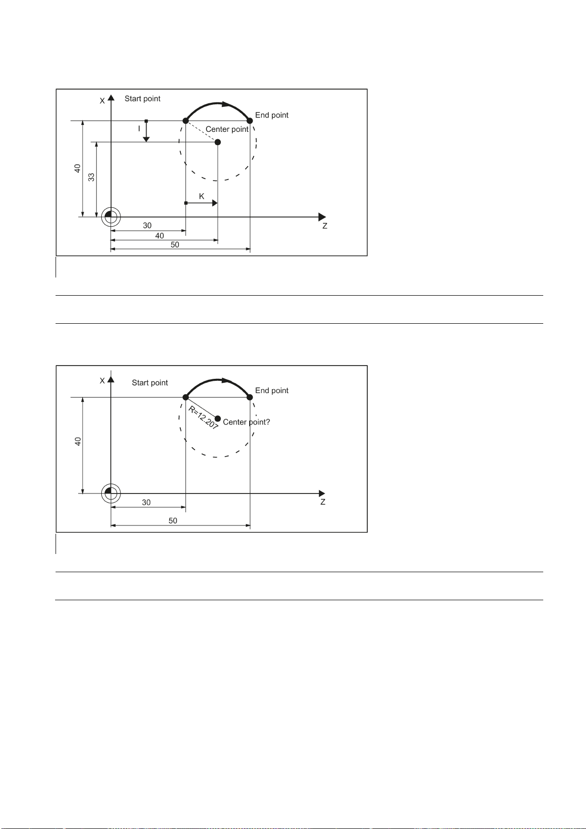
Programming example: Definition of center point and end point
N5 G90 Z30 X40
; Starting point circle for N10
N10 G2 Z50 X40 K10 I-7
; End point and center point
Note
Programming example: End point and radius specification
N5 G90 Z30 X40
; Starting point circle for N10
N10 G2 Z50 X40 CR=12.207
; End point and radius
Note
Center point values refer to the circle starting point!
With a negative leading sign for the value with CR=-..., a circular segment larger than a semicircle is selected.
Programming and Operating Manual (Turning)
6FC5398-5DP10-0BA2, 06/2015
73

Programming example: Definition of end point and aperture angle
N5 G90 Z30 X40
; Starting point circle for N10
N10 G2 Z50 X40 AR=105
; Opening angle and end point
Programming example: Definition of center point and aperture angle
N5 G90 Z30 X40
; Starting point circle for N10
N10 G2 K10 I-7 AR=105
; Opening angle and center point
Note
8.4.2
Circular interpolation via intermediate point: CIP
Functionality
and
Center point values refer to the circle starting point!
The direction of the circle results here from the position of the intermediate point (between starting and end points).
Specification of intermediate point: I1=... for the X axis, K1=... for the Z axis.
CIP remains active until canceled by another instruction from this G group (G0, G1...).
The configured dimensional data G90 or G91 applies to the end point
Programming and Operating Manual (Turning)
74 6FC5398-5DP10-0BA2, 06/2015
the intermediate point.

Programming example
N5 G90 Z30 X40
; Starting point circle for N10
N10 CIP Z50 X40 K1=40 I1=45
; End point and intermediate point
8.4.3
Circle with tangential transition: CT
Functionality
8.5
Thread cutting
8.5.1
Thread cutting with constant lead: G33
Functionality
See the following illustration for circle with end point and intermediate point specification:
With CT and the programmed end point in the current plane (G18: Z/X plane), a circle is produced which tangentially
connects to the previous path segment (circle or straight line).
This defines the radius and center point of the circle from the geometric relationships of the previous path section and the
programmed circle end point.
See the following illustration for circle with tangential transition to the previous path section:
The function G33 can be used to machine threads with constant lead of the following type:
● Thread on cylindrical structures
● Thread on tapered structures
● External thread
● Single- and multiple-start thread
● Multi-block thread (series of threads)
This requires a spindle with position measuring system.
G33 remains active until canceled by another instruction from this G group (G0, G1, G2, G3...).
Programming and Operating Manual (Turning)
6FC5398-5DP10-0BA2, 06/2015
75

Right-hand or left-hand thread
Programming
See the following illustration for external and internal thread with cylindrical thread:
Right-hand or left-hand thread is set with the rotation direction of the spindle (M3 right, M4 left). To do this, the rotation value
must be programmed under address S or a rotation speed must be set.
Remark: Run-in and run-out paths must be taken into account for the thread lengths.
See the following illustration for programmable values for the thread with G33:
Programming and Operating Manual (Turning)
76 6FC5398-5DP10-0BA2, 06/2015

Tapered thread
larger travel
Starting point offset SF=
SF
Please note:
Programming example
Cylindrical thread
N10 G54 G0 G90 X50 Z0 S500 M3
; Approach starting point, clockwise spindle rotation
N20 G33 Z-100 K4 SF=0
;Lead: 4 mm/rev
N30 G0 X54
N40 Z0
N50 X50
N60 G33 Z-100 K4 SF=180
; 2nd thread, offset by 180 degrees
N70 G0 X54
N80 Z0
N90 G0X50Z50
N100 M30
Multi-block thread
See the following illustration for lead assignment for cylindrical, tapered and transversed thread:
For tapered threads (2 axis values required), the required lead address I or K of the axis with the
(longer thread)
must be used. A second lead is not defined.
A starting point offset is required for the spindle if a multiple-start thread or a thread in offset sections is to be machined. The
starting point offset is programmed in the thread block with G33 under the address
(absolute position).
If no starting point offset SF is written, the value from the setting data "Starting angle of thread" is active (SD 4200:
THREAD_START_ANGLE) is active.
A programmed value for SF must always be entered in the setting data.
, double-thread, starting point offset 180 degrees, thread length (including run-in and run-out) 100 mm,
thread lead 4 mm/rev.
If multiple thread blocks are programmed consecutively (multi-block thread), it only makes sense to define a starting point
offset in the 1st thread block. The value is only used here.
Multi-block threads are connected automatically in G64 continuous path mode.
Programming and Operating Manual (Turning)
6FC5398-5DP10-0BA2, 06/2015
77

Axis velocity
feedrate F is not relevant
Information
Important
8.5.2
Programmable run-in and run-out path for G33: DITS, DITE
Functionality
Programming
Values for DITS and DITE or SD42010: THREAD_RAMP_DISP
in and
See the following example of multi-block thread chaining:
With G33 threads, the velocity of the axes for the thread length is determined on the basis of the spindle speed and the
thread lead. The
defined in the machine data cannot be exceeded. This will result in an alarm.
● The spindle speed override switch should remain unchanged for thread machining.
● The feedrate override switch has no meaning in this block.
. It is, however, stored. However, the maximum axis velocity (rapid traverse)
The run-in and run-out path must also be traversed to the required thread with thread G33. The starting and braking of the
axis (both axes in case of a tapered thread) are performed in these areas. This path depends on the thread lead, spindle
speed, and the axis dynamics (configuration).
If the available path for run-in or run-out is limited, it may be necessary to reduce the spindle speed so that this path is
sufficient.
In this case, the run-in and run-out paths can be specified separately in the program to achieve favorable cutting values and
short machining times or to simplify the handling of this issue. If no values are specified, the values from the setting data
(SD) apply. The specifications in the program are written into SD42010: THREAD_RAMP_DISP[0] ... [1].
If this path is not sufficient for the traversing with the configured axis acceleration, the axis is overloaded in terms of
acceleration. Alarm 22280 ("Programmed run-in path too short") is then issued for the thread run-in. The alarm is purely for
information and has no effect on part program execution.
The run-out path acts as a rounding clearance at the end of the thread. This achieves a smooth change in the axis
movement when retracting.
DITS=... ; Run-in path of thread for G33
DITE=... ; Run-out path of thread for G33
-1 ... < 0: Starting/braking of the feed axis is carried out with the configured acceleration.
Jerk according to current BRISK/SOFT programming.
0: Abrupt starting/braking of the feedrate axis on thread cutting.
> 0: The run-in/run-out path of the thread is predefined for G33.
To avoid alarm 22280, the acceleration limits of the axis must be observed in case of very small runrun-out paths.
Note: The value of SD42010 after reset/program start is -1.
Programming and Operating Manual (Turning)
78 6FC5398-5DP10-0BA2, 06/2015

Programming example
N10 G54
N20 G90 G0 Z100 X10 M3 S500
N30 G33 Z50 K5 SF=180 DITS=4 DITE=2
; run-in 4 mm, run-out 2 mm
N40 G0 X30
N50 G0 X100 Z100
N60 M5
N70 M30
8.5.3
Thread cutting with variable lead: G34, G35
Functionality
Determining F
See the following illustration for run-in path and run-out path with corner rounding:
Threads with variable lead can be produced in one block with G34 or G35:
● G34 ; Thread with (linearly) increasing lead
● G35 ; Thread with (linearly) decreasing lead.
Both functions otherwise have the same functionality as G33 and have the same prerequisites.
G34 or G35 remain active until canceled by another instruction from this G group (G0, G1, G2, G3, G33...).
Thread lead:
● I or K; Starting thread lead in mm/rev., associated with X or Z axis
Lead change:
In the block with G34 or G35, the address F contains the meaning of the lead change:
The lead (mm per revolution) changes per revolution.
● F ; lead change in mm/
rev.
2
.
Note: Outside of G34, G35, the address F also indicates the feed or the dwell time for G4. The values programmed there
remain saved.
If you already know the starting and final lead of a thread, you can calculate the thread lead change F to be programmed
according to the following equation:
Explanation:
K
Thread lead of the axis end point coordinate [mm/rev]
e
K
Initial thread lead (under I, K progr.) [mm/U]
a
L
Thread length in [mm]
G
Programming and Operating Manual (Turning)
6FC5398-5DP10-0BA2, 06/2015
79

Programming
Programming example
N10 M3 S40
; Switch on spindle
N20 G0 G54 G90 G64 Z10 X60
; Approach starting point
N30 G33 Z-100 K5 SF=15
;Thread, constant lead 5mm/rev,
; Activation point at 15 degrees
N40 G35 Z-150 K5 F0.16
;Starting pitch 5 mm/rev,
; Pitch decrease 0.16 mm/rev,
; Thread length 50 mm,
;Desired lead at end of block 3 mm/rev
N50 G0 X80
; Retraction in X
N60 Z120
N100 M2
8.5.4
Thread interpolation: G331, G332
Functionality
without
Right-hand or left-hand thread
sign of the thread lead
Axis velocity
feedrate F is not relevant
Programming example
N10 G54 G0 G90 X10 Z5
; Approach starting point
N20 SPOS=0
;Spindle in position control
N30 G331 Z-25 K0.8 S600
; Thread grinding, K positive = Clockwise rotation of spindle,
end point -25 mm
N40 G332 Z5 K0.8
; Retraction
N50 G0 X10 Z5
N60 M30
G34 Z... K... F... ;Cylindrical thread with increasing lead
G35 X... I... F... ;Face thread with decreasing lead
G35 Z... X... K... F... ;Taper thread with decreasing lead
A position-controlled spindle with position measuring system is required.
With G331/G332, threads
allow this.
If a compensating chuck is used nevertheless, the position differences to be compensated for by the compensating chuck
are reduced. This allows thread grinding at higher spindle speeds.
G331 applies for grinding, G332 for grinding in opposite direction.
The grinding depth is specified through the axis, e.g. Z; the thread lead through the corresponding interpolation parameter
(here: K).
For G332, the same lead is programmed as for G331. The spindle direction of rotation is automatically reversed.
The spindle speed is programmed with S; without M3/M4.
Before thread grinding with G331/G332, the spindle must be brought into the closed-loop position controlled mode using
SPOS=... .
compensating chuck can be drilled, if the dynamic response of the spindle and the axis
The
determines the direction of spindle rotation:
positive: right-hand (as with M3)
Negative: Left-hand (as with M4)
For G331/G332, the velocity of the axis for the thread length results from the spindle speed and the thread lead. The
. It is, however, stored. However, the maximum axis velocity (rapid traverse) defined in the machine
data cannot be exceeded. This will result in an alarm.
Metric thread 5,
lead according to the table: 0.8 mm/rev., hole already premachined:
Programming and Operating Manual (Turning)
80 6FC5398-5DP10-0BA2, 06/2015

8.6
Fixed point approach
8.6.1
Fixed point approach: G75
Functionality
Programming
Note
Command
Significance
Programming example
N05 G75 FP=1 X=0
; Approach fixed point 1 in X
N10 G75 FP=2 Z=0
; Approach fixed point 2 in Z, e.g. for tool
change
N30 M30
; End of program
Note
8.6.2
Reference point approach: G74
Functionality
Programming example
N10 G74 X=0 Z=0
Note
By using G75, a fixed point on the machine, e.g. tool change point, can be approached. The position is stored permanently
in the machine data for all axes. A maximum of four fixed points can be defined for each axis.
No offset is effective. The velocity of each axis is its rapid traverse.
G75 requires a separate block and acts non-modal. The machine axis identifier must be programmed!
In the part program block after G75, the previous G command of the "Interpolation type" group (G0, G1,G2, ...) is active
again.
G75 FP=<n> X=0 Z=0
FPn is referencing with axis machine date MD30600 $MA_FIX_POINT_POS[n-1]. If no FP is programmed, then the first
fixed point is selected.
G75 Fixed point approach
FP=<n> Fixed point that is to be approached. The fixed point number is specified: <n>
Value range of <n>: 1, 2, 3, 4
MD30610$NUM_FIX_POINT_POS should be set if fixed point number 3 or 4 is to be used.
If no fixed point number is specified, fixed point 1 is approached automatically.
X=0 Z=0 Machine axes to be traversed to the fixed point.
Specify the axes with value "0" with which the fixed point is to be approached simultaneously.
Each axis is traversed with the maximum axial velocity.
The programmed position values for X, Z (any value, here = 0) are ignored, but must still be written.
The reference point can be approached in the NC program with G74. The direction and speed information of each axis is
stored in the machine data.
G74 needs a separate block and is active based on the block mode. The machine axis identifier must be programmed!
In the block after G74, the previous G command of the "Interpolation type" group (G0, G1,G2, ...) is active again.
The programmed position values for X, Z (here = 0) are ignored, but must still be written.
Programming and Operating Manual (Turning)
6FC5398-5DP10-0BA2, 06/2015
81
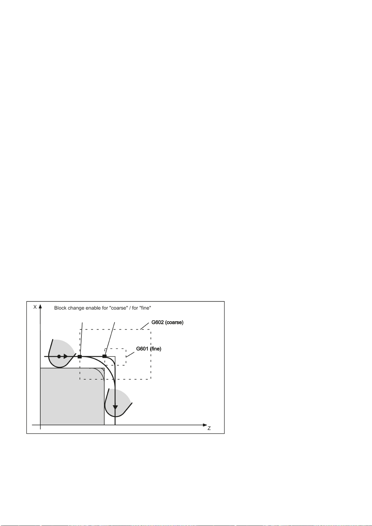
8.7
Acceleration control and exact stop/continuous path
8.7.1
Exact stop/continuous-path control mode: G9, G60, G64
Functionality
Programming
Exact stop G60, G9
G functions are provided for optimum adaptation to different requirements to set the traversing behavior at the block borders
and for block advancing. For example, you would like to quickly position with the axes or you would like to machine path
contours over multiple blocks.
G60 ; Exact stop, modal
G64 ; Continuous-path mode
G9 ; Exact stop, non-modal
G601 ; Exact stop window fine
G602 ; Exact stop window coarse
If the exact stop function (G60 or G9) is active, the velocity for reaching the exact end position at the end of a block is
decelerated to zero.
Another modal G group can be used here to set when the traversing movement of this block is considered ended and the
next block is started.
● G601 Exact stop window fine
Block advance takes place when all axes have reached the "Exact stop window fine" (value in the machine data).
● G602 Exact stop window coarse
Block advance takes place when all axes have reached the "Exact stop window coarse" (value in the machine data).
The selection of the exact stop window has a significant influence on the total time if many positioning operations are
executed. Fine adjustments require more time.
See the following illustration for comparison of the G60 and G64 velocity behavior:
Programming and Operating Manual (Turning)
82 6FC5398-5DP10-0BA2, 06/2015

Programming example
N5 G602
; Exact stop window coarse
N10 G0 G60 Z10
; Exact stop modal
N20 X20 Z0
;G60 continues to act
N30 X30 Z-40
N40 M3 S1000
N50 G1 G601 X35 Z-50 F0.12
; Exact stop window fine
N60 G64 Z-65
;Switching over to continuous-path mode
N70 X40 Z-70
N80 G0 G9 Z-80
; Exact stop acts only in this block
N90 X45 Z-90
;Again continuous-path mode
N100 M30
Continuous-path control mode G64
to the next
block
a path velocity as constant as possible
look-ahead
velocity control
Programming example
N10 G64 G1 Z5 F0.15 M3 S800
; Continuous-path mode
N20 X20 Z0
; Continuous-path control mode continues to be active
N30 Z-40
N40 G60 X30 Z-50
; Switching over to exact stop
N50 X45 Z-70
N60 M30
Look-ahead velocity control
Remark: The G9 command only generates exact stop for the block in which it is programmed; G60, however, is effective
until it is canceled by G64.
The objective of the continuous-path control mode is to avoid deceleration at the block boundaries and to switch
with
over several blocks.
(in the case of tangential transitions). The function works with
For non-tangential transitions (corners), the velocity can be reduced rapidly enough so that the axes are subject to a
relatively high velocity change over a short period of time. This may lead to a significant jerk (acceleration change). The size
of the jerk can be limited by activating the SOFT function.
In the continuous-path control mode with G64, the control system determines the velocity control for several NC blocks in
advance automatically. This enables acceleration and deceleration across multiple blocks with approximately tangential
transitions. For paths that consist of short travels in the NC blocks, higher velocities can be achieved than without look
ahead.
Programming and Operating Manual (Turning)
6FC5398-5DP10-0BA2, 06/2015
83

8.7.2
Acceleration pattern: BRISK, SOFT
BRISK
SOFT
Programming
Programming example
N10 M3 S200
N20 SOFT G1 X30 Z84 F6.5
; Jerk-limited path acceleration
N30 X46 Z92
N40 BRISK X87 Z104
; continuing with jerking path acceleration
N50 X95 Z110
N60 M30
8.7.3
Dwell Time: G4
Functionality
own block
Programming
Programming example
N5 G1 F3.8 Z-50 S300 M3
;Feed F; spindle speed S
N10 G4 F2.5
; Dwell time 2.5 seconds
N20 Z70
N30 G4 S30
;dwelling 30 revolutions of the spindle, corresponds at
; S=300 rpm and 100 % speed override to: t=0.1 min
N40 X20
;Feed and spindle speed remain effective
N50 M30
Remark
The axes of the machine change their velocities using the maximum permissible acceleration value until reaching the final
velocity. BRISK allows time-optimized working. The set velocity is reached in a short time. However, jumps are present in
the acceleration pattern.
The axes of the machine accelerate with nonlinear, constant curves until reaching the final velocity. With this jerk-free
acceleration, SOFT allows for reduced machine load. The same behavior can also be applied to braking procedures.
See the following illustration for principle course of the path velocity when using BRISK or SOFT:
BRISK ; Jerking path acceleration
SOFT ; Jerk-limited path acceleration
Between two NC blocks you can interrupt the machining process for a defined period by inserting your
with G4;
e.g. for relief cutting.
Words with F... or S... are only used for times in this block. Any previously programmed feedrate F or a spindle speed S
remain valid.
G4 F... ; Dwell time in seconds
G4 S... ; Dwell time in spindle revolutions
G4 S.. is only possible if a controlled spindle is available (if the speed specifications are also programmed via S...).
Programming and Operating Manual (Turning)
84 6FC5398-5DP10-0BA2, 06/2015

8.8
The third axis
Prerequisite
Functionality
Programming example
The 3rd axis is a rotary axis with the axis identifier C
N5 G94
; feedrate F in mm/min or degrees/min
N10 G0 X10 Z30 C45
; X-Z traverse path with rapid traverse, C at the same time
N20 G1 X12 Z33 C60 F400
; X-Z traverse path at 400 mm/min, C at the same time
N30 G1 C90 F3000
; Axis C traverses alone to position 90 degrees at a speed of 3000
degrees/min
Special instructions for rotary axes: DC, ACP, ACN
For example, for rotary axis A:
A=DC(...)
; Absolute dimensions, approach position directly (on the shortest
path)
A=ACP(...)
; Absolute dimensions, approach position in positive direction
A=ACN(...)
; Absolute dimensions, approach position in negative direction
Example:
N10 A=ACP(55.7)
; approach absolute position 55.7 degrees in positive direction
8.9
Spindle movements
8.9.1
Spindle speed S, directions of rotation
Functionality
Programming
Remark
The control system itself must be designed for three axes.
Depending on the machine design, the third axis can be required. These axes can be implemented as linear or rotary axes.
The identifier for these axes is defined by the machine manufacturer (e.g. C).
For rotary axes, the traversing range can be configured between 0 ...<360 degrees (modulo behavior) or -360 degrees/+360
degrees if there is no modulo axis is present.
With an appropriate machine design, a 3rd axis can be traversed linear simultaneously with the remaining axes. If the axis is
traversed in a block with G1 or G2/G3 with the remaining axes (X, Z), it does not receive a component of the feedrate F. Its
speed conforms to the path time of axes X, Z. Its movement begins and ends with the remaining path axes. However, the
speed cannot exceed the defined limit value.
If a block is programmed with this 3rd axis only, the axis will traverse using the active feedrate F when the G1 function is
executed. If the axis is a rotary axis, the unit of measurement for F is degrees/min with G94 or degrees/rev. of the spindle
with G95.
For these axes, offsets can be set (G54 ... G59) and programmed (TRANS, ATRANS).
The spindle speed is programmed under the address S in revolutions per minute, if the machine has a controlled spindle.
The direction of rotation and the beginning or end of the movement are specified via M commands.
M3 ; Spindle clockwise
M4 ; Spindle counter-clockwise
M5 ; Spindle stop
: For integer S values, the decimal point can be omitted, e.g. S270.
Programming and Operating Manual (Turning)
6FC5398-5DP10-0BA2, 06/2015
85

Information
block with axis movements
before
Standard setting:
Note:
Programming example
N10 G1 X70 Z20 F3 S270 M3
; before the axis traversing X, Z the spindle accelerates to 270
r.p.m., clockwise
N20 X90 Z0
N30 Z-40
N40 M5
N50 M4 S290
N60 G1 X100 Z50
N70 S450 Z100
; Speed change
N80 X150 Z150
N90 G0 Z180 M5
; Z movement, spindle comes to a stop
N100 M30
8.9.2
Spindle positioning
8.9.2.1
Spindle positioning (SPOS, SPOSA, M19, M70, WAITS)
Functionality
Positioning in axis mode
End of positioning
If you write M3 or M4 in a
Axis movements will only start once the spindle has accelerated to speed (M3, M4). M5 is also issued
before the axis movement. However, it does not wait for the spindle to stop. Axis motion already starts before the spindle
comes to a standstill.
The spindle is stopped with the end of the program or with the following key:
At the beginning of the program, the spindle speed is zero (S0).
Other settings can be configured via machine data.
, the M commands become active
the axis movements.
SPOS, SPOSA or M19 can be used to set the spindle to specific angular positions, e.g. during tool change.
SPOS, SPOSA and M19 induce a temporary switchover to position-controlled mode until the next M3/M4/M5/M41 to M45.
The spindle can also be operated as a path axis, synchronized axis or positioning axis at the address defined in the machine
data. When the axis identifier is specified, the spindle is in axis mode.
M70 switches the spindle directly to axis mode.
The end-of-motion criterion when positioning the spindle can be programmed using FINEA, CORSEA, or IPOENDA.
Programming and Operating Manual (Turning)
86 6FC5398-5DP10-0BA2, 06/2015

Synchronization
Conditions
Programming
Significance
SPOSA enables the NC block even if the position has not been reached.
=<value>: as DC(<value>)
The NC block is not enabled until the position has been reached.
No defined position is approached. The NC block is enabled after the switchover has been performed.
FINEA:
Motion end when "Exact stop fine" reached
COARSEA:
Motion end when "Exact stop coarse" reached
IPOENDA:
End of motion on reaching "interpolator stop"
IPOBRKA:
A block change is possible in the braking ramp.
The program advances to the next block if the end of motion criteria for the spindle or axes programmed in the current block
plus the block change criterion for path interpolation are fulfilled.
In order to synchronize spindle movements, WAITS can be used to wait until the spindle position is reached.
The spindle to be positioned must be capable of operation in position-controlled mode.
Position spindle:
SPOS=<value>
SPOSA=<value>
M19/M<n>=19
Switch spindle over to axis mode:
M70/M<n>=70
Define end-of-motion criterion:
FINEA/FINEA[S<n>]
COARSEA/COARSEA[S<n>]
IPOENDA/IPOENDA[S<n>]
IPOBRKA/IPOBRKA(<axis>[,<instant in time>]) ; Programming in a separate NC block.
Synchronize spindle movements:
WAITS/WAITS(<n>,<m>) ; Programming in a separate NC block.
SPOS/SPOSA: Set spindle to specified angle
SPOS and SPOSA have the same functionality but differ in their block change behavior:
•
SPOS delays the enabling of the NC block until the position has been reached.
•
<value>: Angular position to which the spindle is to be set.
Unit: degrees
Type: REAL
The following options are available about programming the position approach mode:
=AC(<value>): Absolute dimensions
Range of values: 0 … 359,9999
=IC(<value>): Incremental dimensions
Range of values: 0 … ±99 999,999
=DC(<value>): Approach absolute value directly
=ACN(<value>): Absolute dimension, approach in negative direction
=ACP(<value>): Absolute dimension, approach in positive direction
M<n>=19: Set the spindle (M19 or M0=19) or spindle number <n> (M<n>=19) to the angular position preset with
SD43240 $SA_M19_SPOS with the position approach mode preset in
SD43250 $SA_M19_SPOSMODE.
M<n>=70: Switch the spindle (M70 or M0=70) or spindle number <n> (M<n>=70) over to axis mode.
Programming and Operating Manual (Turning)
6FC5398-5DP10-0BA2, 06/2015
87

<axis>: Channel axis identifier
Note:
IBOBRKA with an instant in time of "0" is identical to IPOENDA.
block with SPOSA has reached its end position (with exact stop fine).
WAITS after M5: Wait for the spindle to come to a standstill.
WAITS after M3/M4: Wait for the spindle to reach its setpoint speed.
spindle.
Note
Note
Note
Note
Programming examples
Example 1: Position spindle with negative direction of rotation
N10 SPOSA[1]=ACN(250)
The spindle is decelerated if necessary and accelerated in the
opposite direction to that of the positioning movement.
<instant in time>: Instant in time of the block change with reference to the braking ramp
Unit: Percent
Range of values: 100 (application point of the braking ramp) to 0 (end of the braking ramp)
If a value is not assigned to the
applied:
SD43600 $SA_IPOBRAKE_BLOCK_EXCHANGE
WAITS: Synchronization command for the specified spindle
The subsequent blocks are not processed until the specified spindle programmed in a previous NC
<n>,<m>: Number of the spindle to which the synchronization command is to be applied.
If the spindle number is not specified or if the spindle number is set to "0", WAITS will be applied to the
Three spindle positions are possible for each NC block.
<instant in time> parameter, the current value of the setting data is
With incremental dimensions IC(<value>), spindle positioning can take place over several revolutions.
If position control was activated with SPCON prior to SPOS, this remains active until SPCOF is issued.
The control system detects the transition to axis mode automatically according to the program sequence. Explicit
programming of M70 in the part program is, therefore, essentially no longer necessary. However, M70 can continue to be
programmed, e.g to increase the legibility of the part program.
Spindle 1 is to be positioned at 250° with negative direction of rotation:
Programming and Operating Manual (Turning)
88 6FC5398-5DP10-0BA2, 06/2015

Example 2: Spindle positioning in axis mode
N10 G0 X100 Z100
N20 M3 S500
N30 G0 X80 Z80
N40 G01 X60 Z60 F0.25
N50 SPOS=0
Position control on, spindle 1 positioned to 0, axis mode can be
used in the next block.
N60 X50 C180
Spindle(C axis) is traversed with linear interpolation synchronous
to X.
N70 Z20 SPOS=90
Spindle is positioned to 90 degrees.
N80 M30
N10 G0 X100 Z100
N20 M3 S500
N30 G0 X80 Z80
N40 G01 X60 Z60 F0.25
N50 M2=70
Spindle switches to axis mode.
N60 X50 C180
Spindle(C axis) is traversed with linear interpolation synchronous
to X.
N70 Z20 SPOS=90
Spindle is positioned to 90 degrees.
N80 M30
Example 3: Drill cross holes in turned part
Program variant 1:
Program variant 2:
Cross holes are to be drilled in this turned part. The running spindle is stopped at zero degrees and then successively turned
through 90°, stopped and so on.
Programming and Operating Manual (Turning)
6FC5398-5DP10-0BA2, 06/2015
89

G0 X100 Z100
N110 S2=1000 M2=3
Switch on cross drilling attachment.
N120 SPOSA=DC(0)
Set main spindle to 0° immediately,
the program will advance to the next block straight away.
N125 G0 X34 Z-35
Switch on the drill while the spindle is taking up position.
N130 WAITS
Wait for the main spindle to reach its position.
N135 G1 G94 X10 F250
Feedrate in mm/min (G96 is suitable only for the multi-edge turn-
cross slide.)
N140G0 X34
N145 SPOS=IC(90)
The spindle is positioned through 90° with read halt in a positive
direction.
N150 G1 X10
N155 G0 X34
N160 SPOS=AC(180)
The spindle is positioned at 180° relative to the spindle zero
point.
N165 G1 X10
N170 G0 X34
N175 SPOS=IC(90)
The spindle turns in a positive direction through 90° from the
absolute 180° position, ending up in the absolute 270° position.
N180 G1 X10
N185 G0 X50
M30
8.9.2.2
Spindle positioning (SPOS, SPOSA, M19, M70, WAITS): Further information
Further information
Positioning with SPOSA
Note
Positioning with SPOS/M19
ing tool and synchronous spindle, but not for power tools on the
The block step enabling or program execution is not affected by SPOSA. The spindle positioning can be performed during
execution of subsequent NC blocks. The program moves onto the next block if all the functions (except for spindle)
programmed in the current block have reached their block end criterion. The spindle positioning operation may be
programmed over several blocks (see WAITS).
If a command, which implicitly causes a preprocessing stop, is read in a following block, execution of this block is delayed
until the positioning spindle is stationary.
The block step enabling condition is met when all functions programmed in the block reach their end-of-block criterion (e.g.
all auxiliary functions acknowledged by the PLC, all axes at their end point) and the spindle reaches the programmed
position.
Programming and Operating Manual (Turning)
90 6FC5398-5DP10-0BA2, 06/2015

Synchronize spindle movements with WAITS
N10 SPOSA[1]=180 SPOSA[1]=0
G01 X34
G00 X10
N40 WAITS(1)
;The block waits until the spindle 1 has reached the
position specified in block N10.
Note
Position spindle from rotation (M3/M4)
Position a spindle from standstill (M5)
Velocity of the movements:
The velocity and the delay response for positioning are stored in the machine data. The configured values can be modified
by programming or by synchronized actions.
Specification of spindle positions:
As the
G90/G91 commands are not effective here, the corresponding dimensions apply explicitly, e.g. AC, IC, DC, ACN, ACP. If
no specifications are made, traversing automatically takes place as for
WAITS can be used to identify a point at which the NC program waits until the spindle programmed with SPOSA in a previous
NC block reaches its position.
Example:
WAITS can be used after M5 to wait until the spindle(s) has (have) stopped. WAITS can be used after M3/M4 to wait until the
spindle has reached the specified speed/direction of rotation.
If the spindle has not yet been synchronized with synchronization marks, the positive direction of rotation is taken from the
machine data (state on delivery).
DC.
When M3 or M4 is active, the spindle comes to a standstill at the programmed value.
There is no difference between
until the absolute end position is reached. With
approach direction is taken. With
DC and AC dimensioning. In both cases, rotation continues in the direction selected by M3/M4
ACN and ACP, deceleration takes place if necessary, and the appropriate
IC, the spindle rotates additionally to the specified value starting at the current spindle
position.
The exact programmed distance is traversed from standstill (M5).
Programming and Operating Manual (Turning)
6FC5398-5DP10-0BA2, 06/2015
91

8.9.3
Gear stages
Functionality
Programming
8.10
Special turning functions
8.10.1
Constant cutting rate: G96, G97
Functionality
Requirement:
Programming
Remark:
Rapid traverse
Exception:
Up to 5 gear stages can be configured for a spindle for speed / torque adaptation.
The relevant gear stage is selected in the program via M commands:
M40 ; Automatic gear stage selection
M41 to M45 ; Gear stages 1 to 5
With activated G96 function, the spindle speed is adapted to the currently machined workpiece diameter (transverse axis)
such that a programmed cutting rate S remains constant on the tool edge:
Spindle speed times diameter = constant.
The S word is evaluated as the cutting rate as of the block with G96. G96 is modally effective until cancellation by another G
function of the group (G94, G95, G97).
G96 S... LIMS=... F... ; Constant cutting speed ON
G97 ; Constant cutting speed OFF
S ; Cutting rate, unit of measurement m/min.
LIMS= ; Upper limit speed of the spindle with G96, G97 effective
F ; Feedrate in mm/revolution - as for G95
If G94 instead of G95 was active before, a new appropriate F value must be written.
See the following illustration for constant cutting rate G96:
A controlled spindle must be present.
With rapid traverse G0, there is no change in speed.
CIP, CT (contour block), then the speed for the contour block is applied already in the approach block with G0.
Programming and Operating Manual (Turning)
If the contour is approached at rapid traverse and the next block contains an interpolation type G1 or G2, G3,
92 6FC5398-5DP10-0BA2, 06/2015

Upper speed limit LIMS=
Deactivate constant cutting rate: G97
S word
spindle speed
Programming example
N10 M3 S1000
; Spindle's direction of rotation
N20 G96 S120 LIMS=2500
; Activate constant cutting speed, 120 m/min, speed limit 2,500
r.p.m.
N30 G0 X150
; no change in speed, because block N31 with G0
N40 X50 Z20
; no change in speed, because block N32 with G0
N50 X40
; Approach on contour, new speed is automatically set as is required
for the beginning of block N40
N60 G1 F0.2 X32 Z25
; Feedrate 0.2 mm/revolution
N70 X50 Z50
N80 G97 X10 Z20
; Deactivating constant cutting rate
N90 S600
; new spindle speed, r.p.m.
N100 M30
Information
programmed
8.10.2
Rounding, chamfer
Functionality
Programming
During machining from large to small diameters, the spindle speed can increase significantly. In this case, it is recommended
to program the upper spindle speed limitation LIMS=... . LIMS is only effective with G96 and G97.
By programming LIMS=..., the value entered into the setting data (SD 43230:
SPIND_MAX_VELO_LIMS) is overwritten. This SD takes effect when LIMS is not written.
The upper limit speed programmed with G26 or defined via machine data cannot be overwritten with LIMS=.
The function "Constant cutting rate" is deactivated by G97. If G97 is active, a programmed
.
If no new S word is programmed, the spindle turns at the last defined speed with G96 function active.
is given in RPM as the
The G96 function can also be deactivated with G94 or G95 (same G group). In this case, the last
spindle speed
S is active for the remaining machining sequence if no new S word is programmed.
The programmable offset TRANS or ATRANS (see Section "Programmable work offset: TRANS, ATRANS (Page 56)")
should not be used on the transverse axis X or used only with low values. The workpiece zero point should be located at the
turning center. Only then is the exact function of G96 guaranteed.
You can insert the chamfer (CHF or CHR) or rounding (RND) elements into a contour corner. If you wish to round several
contour corners sequentially by the same method, use "Modal rounding" (RNDM).
You can program the feedrate for the chamfer/rounding with FRC (non-modal) or FRCM (modal). If FRC/FRCM is not
programmed, the normal feedrate F is applied.
CHF=... ; Insert chamfer, value: Length of chamfer
CHR=... ; Insert chamfer, value: Side length of the chamfer
RND=... ; Insert rounding, value: Radius of chamfer
RNDM=... ; Modal rounding:
Value >0: Radius of chamfer, modal rounding ON
This rounding is inserted in all contour corners.
Value = 0: Modal rounding OFF...
FRC=... ; Non-modal feedrate for chamfer/rounding
Value >0, feedrate in mm/min (G94) or mm/rev. (G95)
Programming and Operating Manual (Turning)
6FC5398-5DP10-0BA2, 06/2015
93

Information
Chamfer CHF or CHR
linear and circle contours
FRCM=... ; Modal feedrate for chamfer/rounding:
Value >0: Feedrate in mm/min (G94) or mm/rev. (G95),
Modal feedrate for chamfer/rounding ON
Value = 0: Modal feedrate for chamfer/rounding OFF
Feedrate F applies to the chamfer/rounding.
The chamfer/rounding functions are executed in the current planes G18 to G19.
The appropriate instruction CHF= ... or CHR=... or RND=... or RNDM=... is written in the block with axis movements leading
to the corner.
The programmed value for chamfer and rounding is automatically reduced if the contour length of an involved block is
insufficient.
No chamfer/rounding is inserted, if
● more than three blocks in the connection are programmed that do not contain any information for traversing in the plane,
● or a plane change is carried out.
F, FRC,FRCM are not active when a chamfer is traversed with G0.
If the feedrate F is active for chamfer/rounding, it is by default the value from the block which leads away from the corner.
Other settings can be configured via machine data.
A linear contour element is inserted between
See the following illustration for inserting a chamfer with CHF using the example: between two straight lines.
in any combination. The edge is broken.
Programming and Operating Manual (Turning)
94 6FC5398-5DP10-0BA2, 06/2015

Programming examples of chamfer
N10 G0 X100 Z100 G94 F100
N20 G1 X80 CHF=5
; Insert chamfer with chamfer length of 5 mm
N30 X50 Z60
N40 X40 Z50
N50 G1 X30 CHR=7
; Insert chamfer with leg length of 7 mm
N60 X10 Z20
N70 X0 Z0
N80 G1 FRC=200 X100 CHR=4
; Insert chamfer with feedrate FRC
N90 X120 Z20
N100 M30
Rounding RND or RNDM
linear and circle contours
See the following illustration for inserting a chamfer with CHR using the example: Between two straight lines.
A circle contour element can be inserted with tangential connection between the
combination.
See the following illustration for examples for inserting roundings:
in any
Programming and Operating Manual (Turning)
6FC5398-5DP10-0BA2, 06/2015
95
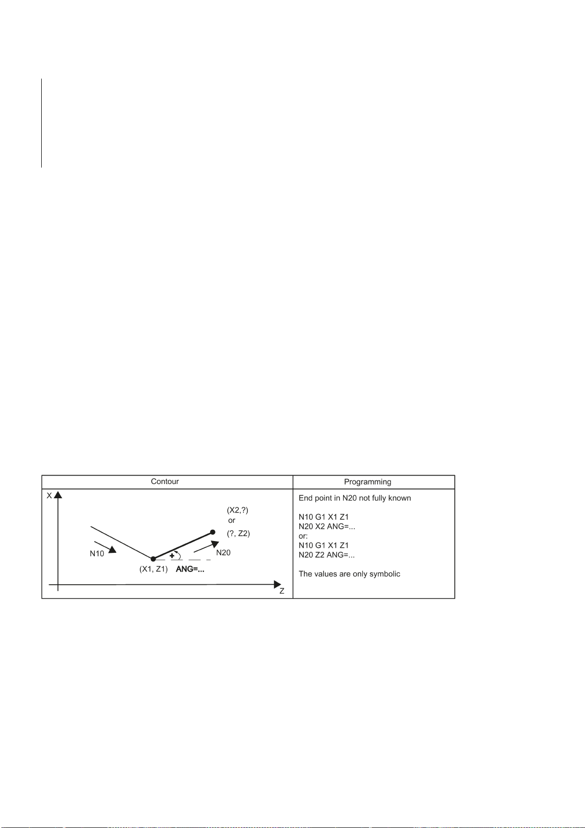
Programming examples for rounding
N10 G0 X100 Z100 G94 F100
N20 G1 X80 RND=8
; Insert 1 rounding with radius 8 mm, feedrate F
N30 X60 Z70
N40 X50 Z50
N50 G1 X40 FRCM= 200 RNDM=7.3
; Modal rounding, radius 7.3 mm with special feedrate FRCM
(modal)
N60 G1 X20 Z10
; continue inserting this rounding - to N70
N70 G1 X0 Z-45 RNDM=0
; Modal rounding OFF
N80 M30
8.10.3
Contour definition programming
Functionality
G0 or G1
Programming
Information
Angle ANG=
If direct end point values for the contour are not visible in a machining drawing, angle values can also be used for straight
line determination. In a contour corner, you can insert the elements chamfer or rounding. The corresponding instruction
CHR= ... or RND=... is written in the block that leads to the corner.
Contour definition programming can be used in blocks with
.
Theoretically, any number of straight-line blocks can be combined and a rounding or chamfer inserted in between. Every
straight line must be clearly identified by point values and/or angle values.
ANG=... ; Specification of angle to define a straight line
RND=... ; Insert rounding, value: Radius of chamfer
CHR=... ; Insert chamfer, value: Side length of the chamfer
If radius and chamfer are programmed in one block, only the radius is inserted regardless of the programming sequence.
An angle can be entered to uniquely define the straight line path if only one end point coordinate of the plane is known for a
straight line or for contours across multiple blocks the cumulative end point. The angle is always referred to the Z axis
(normal case: G18 active). Positive angles are aligned counter-clockwise.
See the following illustration for angle value for determination of a straight line:
Programming and Operating Manual (Turning)
96 6FC5398-5DP10-0BA2, 06/2015

8.11
Tool and tool offset
8.11.1
General information (turning)
Functionality
See the following illustration for examples of multi-block contours:
During program creation for the workpiece machining, you do not have to take tool lengths or cutting radius into
consideration. You program the workpiece dimensions directly, e.g. according to the drawing.
The tool data must be entered separately in a special data area.
In the program, you will merely call the required tool with its offset data. The control system performs the required path
compensations based on the data to create the described workpiece.
Programming and Operating Manual (Turning)
6FC5398-5DP10-0BA2, 06/2015
97

8.11.2
Tool T (turning)
Functionality
tool change
preselection
M6.
Note:
Programming example
8.11.3
Tool offset number D (turning)
Functionality
D1 is automatically
D0
ineffective
Programming
See the following illustration for machining a workpiece with different tool dimensions:
The tool selection takes place when the T word is programmed. Whether this is a
defined in the machine data:
● A tool change (tool call) takes place directly with the T word (e.g. typical for tool turrets on turning machines)
or
● The change takes place after the preselection with the T word by an additional instruction
Tool change without M6
N10 T1
N20 T3
N30 T2
N40 T6
N50 T7
N60 T5
N70 T588
N80 M30
The control system can store a maximum of 64 tools.
If a certain tool was activated, it remains stored as an active tool even beyond the end of the program and after switching
off/switching on the control system.
If you change a tool manually, input the change also in the control system so that the control system 'knows' the correct
tool. For example, you can start a block with the new T word in MDA mode.
or only a
is
It is possible to assign 1 to 9 data fields with different tool offset blocks (for multiple cutting edges) to a specific tool. If a
special cutting edge is required, then it can be programmed using D and the appropriate number.
If a D word is not written,
If
D... ; Tool offset number: 1 ... 9, D0: No offsets active!
Programming and Operating Manual (Turning)
is programmed, the offsets for the tool are
effective.
.
98 6FC5398-5DP10-0BA2, 06/2015

Information
Tool length compensations
immediately
tool radius compensation
Programming example
N10 T1
; Tool 1 is activated with the associated D1
N20 G0 X100
; The length offset compensation is overlaid here
N30 Z100
N40 T4 D2
; Load tool 4, D2 from T4 is active
N50 X50 Z50
N60 G0 Z62
N70 D1
; D1 for tool 4 active, only cutting edge changed
N80 M30
Contents of a compensation memory
A maximum of 64 data fields (D numbers) for tool offset blocks can be stored in the control system simultaneously:
the values of D1.
The compensation is retracted with the first programmed traversing of the associated length compensation axis.
A
Tool change:
become effective
when the tool is active; when no D number was programmed with
must also be activated by G41/G42.
● Geometrical dimensions: Length, radius.
They consist of several components (geometry, wear). The control system takes into account the components to obtain a
resulting dimension (e.g. overall length 1, total radius). The respective overall dimension becomes active when the offset
memory is activated.
The way in which these values are computed in the axes is determined by the tool type and the current plane G17, G18,
G19.
● Tool type
The tool type (drill or turning tool) determines which geometry data are required and how they will be calculated.
● Cutting edge position
For the "turning tool" tool type, you must also enter the cutting edge position.
The following figures provide information on the required tool parameters for the respective tool type.
Programming and Operating Manual (Turning)
6FC5398-5DP10-0BA2, 06/2015
99

See the following illustration for turning tool with two cutting edges D1 and D2_length compensation:
See the following illustration for compensations for turning tool with tool radius compensation:
Programming and Operating Manual (Turning)
100 6FC5398-5DP10-0BA2, 06/2015
 Loading...