

Siemens SICAM Q80 System Manual
s
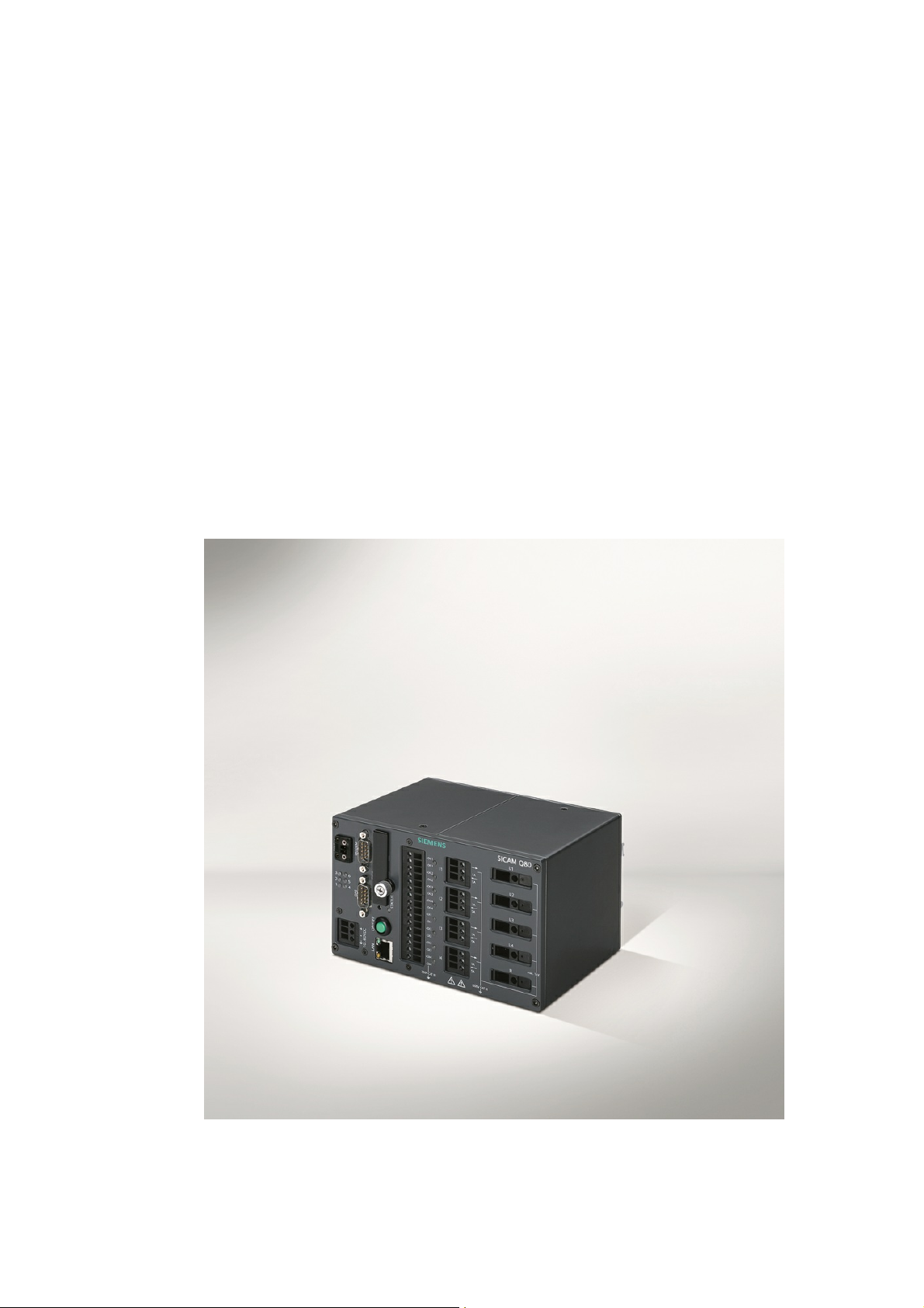
Power Quality Recorder
SICAM Q80
System manual
E50417-H1076-C420-A2
Document version 3.3 12.01.2015


Table of Contents
1 SICAM Q80 5
2 Foreword 7
3 Introduction 11
4 QuickStart 17
5 Operation modes and settings 20
6 Operation of the Software 155
3
7 Extras 202
8 Appendix 234
Power Quality Recorder SICAM Q80 7KG8080, System manual
E50417-H1076-C420-A2, Release 12.01.2015


1 SICAM Q80
Note
Please observe the instructions and warnings for your safety in chapter foreword "Information for
your safety "
Disclaimer of liability
The contents of this documentation have been carefully checked
for consistency with the hardware and software systems
described. Nevertheless, it is impossible to completely rule out
inconsistencies, so that we decline to offer any guarantee of total
conformity.
The statements made in this document are regularly checked and
any necessary corrections are reflected in subsequent editions.
We gratefully accept any suggestions for improvements.
We reserve the right to make technical modifications of the
systems.
Document version 3.3
Release 12.01.2015
Copyright
Copyright © Siemens AG 2013
This document shall not be transmitted or reproduced, nor shall
its contents be exploited or disclosed to third parties without prior
written consent from Siemens. Offenders will be liable for
damages. All rights, including rights created by patent grant or
registration of a utility model or design, are reserved
Registered Trademarks
SIPROTEC®, DIGSI®, OSCOP® and SICAM® are registered
trademarks of SIEMENS AG.
Other designations in this manual might be trademarks whose
useby third parties for their own purposes would infringe the rights
of the owner.
5SICAM Q80
9
Power Quality Recorder SICAM Q80 7KG8080, System manual
E50417-H1076-C420-A2, Release 12.01.2015

6 SICAM Q80 7KG8080
Power Quality Recorder SICAM Q80 7KG8080, System manual
E50417-H1076-C420-A2, Release 12.01.2015

2 Foreword
Purpose of the manual
This manual generally describes the installation, commissioning, parameterization and operation of the power
quality recorder SICAM Q80 7KG8080.
Target audience
This manual is intended for project engineers, commissioning and operating personnel in electrical systems
and power plants.
Validity of the manual
This manual is valid for the power quality recorder SICAM Q80 7KG8080.
Additional support
For any questions concerning your system, please contact your local Siemens representative.
Hotline
Our Customer Support Center provides around-the-clock service.
Phone: +49 180 5 247000
Fax: +49 180 5 242471
Email: support.energy@siemens.com
FAQ: www.siemens.de/energy/support-faq
7Foreword
Courses
Please contact our Training Center to learn about our offers of personal training courses:
Siemens AG
Power Transmission and Distribution
Siemens Power Academy
Humboldtstr. 59
90459 Nürnberg
Phone.: +49 911433-7005
Fax: +49 911433-7929
Internet: www.siemens.com/energy/power-academy-td
Email: power-academy.ptd@siemens.com
Power Quality Recorder SICAM Q80 7KG8080, System manual
E50417-H1076-C420-A2, Release 12.01.2015

8 SICAM Q80 7KG8080
2.1
Copyright-note for Open-Source-products
Copyright (c) 1998 - 2008, Paul Johnston & Contributors (http://pajhome.org.uk/crypt/md5/index.html)
All rights reserved.
Redistribution and use in source and binary forms, with or without modification, are permitted provided that the
following conditions are met:
Redistributions of source code must retain the above copyright notice, this list of conditions and the following
disclaimer. Redistributions in binary form must reproduce the above copyright notice, this list of conditions and
the following disclaimer in the documentation and/or other materials provided with the distribution.
Neither the name of the author nor the names of its contributors may be used to endorse or promote products
derived from this software without specific prior written permission.
THIS SOFTWARE IS PROVIDED BY THE COPYRIGHT HOLDERS AND CONTRIBUTORS "AS IS" AND ANY
EXPRESS OR IMPLIED WARRANTIES, INCLUDING, BUT NOT LIMITED TO, THE IMPLIED WARRANTIES
OF MERCHANTABILITY AND FITNESS FOR A PARTICULAR PURPOSE ARE DISCLAIMED. IN NO EVENT
SHALL THE COPYRIGHT OWNER OR CONTRIBUTORS BE LIABLE FOR ANY DIRECT, INDIRECT,
INCIDENTAL, SPECIAL, EXEMPLARY, OR CONSEQUENTIAL DAMAGES (INCLUDING, BUT NOT LIMITED
TO, PROCUREMENT OF SUBSTITUTE GOODS OR SERVICES; LOSS OF USE, DATA, OR PROFITS; OR
BUSINESS INTERRUPTION) HOWEVER CAUSED AND ON ANY THEORY OF LIABILITY, WHETHER IN
CONTRACT, STRICT LIABILITY, OR TORT (INCLUDING NEGLIGENCE OR OTHERWISE) ARISING IN ANY
WAY OUT OF THE USE OF THIS SOFTWARE, EVEN IF ADVISED OF THE POSSIBILITY OF SUCH
DAMAGE.
Power Quality Recorder SICAM Q80 7KG8080, System manual
E50417-H1076-C420-A2, Release 12.01.2015

9Foreword
Danger
indicates that death, severe personal injury or substantial property damage can result if proper
precautions are not taken.
Warning
indicates that death, severe personal injury or substantial property damage can result if proper
precautions are not taken.
Caution
indicates that minor personal injury or property damage can result if proper precautions are not
taken. This particularly applies to damage on or in the device itself and consequential damage
thereof.
Attention
indicates that property damage can result if proper precautions are not taken.
Note
indicates information about the device or respective part of these operating instructions which is
essential to highlight.
2.2
Information for your safety
This manual does not represent a complete listing of all the safety measures required to operate he equipment
(module, device) since specific operating conditions may make further measures necessary.
However, it contains information which you have to observe in order to ensure your personal safety and in order to
avoid material damage. The information is highlighted by a warning triangle and, depending on the degree of danger,
is shown as follows:
Power Quality Recorder SICAM Q80 7KG8080, System manual
E50417-H1076-C420-A2, Release 12.01.2015
10 SICAM Q80 7KG8080
Qualified personnel
Commissioning and operation of the equipment (module, device) described in this manual may
only be performed by qualified personnel. Qualified personnel, in the context of the safety
information contained in this manual, are persons authorized to commission, start-up, ground and
label devices, systems and circuits according to all applicable safety standards.
Use for the intended purpose
The equipment (device, module) may only be used for the applications specified in the catalog and
the technical manual, and only in connection with OEM devices and components recommended
and approved by SIEMENS-.
The prerequisites for trouble-free, reliable operation of the product include proper transport, proper
storage, proper installation and assembly, as well as proper operation and maintenance.
When operating electrical equipment, certain parts of this equipment are subject to dangerous
voltage levels. Therefore, improper handling can result in serious injury or equipment damage:
The equipment must be grounded at the PG terminal before making any connections
whatsoever.
Dangerous voltages may occur in all circuit components connected to the inputs or power
supply.
Dangerous voltages due to capacitor memory may still exist in the equipment even after it
has been disconnected from the power supply or input circuits.
Equipment with current transformer circuits must never be operated in any state where
the current transformer circuits are open-circuited.
The operating limits specified in the manual and in the operating instructions must not be
exceeded at any time (including inspection and commissioning).
The parameter value limits stated in the instructions may not be exceeded; this also applies to
inspection and commissioning situations.
This product complies with the directive of the Council of the European Communities on the
approximation of the laws of the Member States relating to electromagnetic compatibility (EMC
Council Directive 2004/108/EC) and concerning electrical equipment for use within specified
voltage limits (Low voltage Directive 2006/95/EC).
This conformity has been established by means of tests conducted by Siemens AG in accordance
of the Council Directive in agreement with the standard IEC 61326-1:2006 for the EMC directives,
and with the standard EN 61010-1 for the low-voltage directive.
The device has been designed and produced for industrial use.
2.3
Qualified personnel
2.4
Statement of Conformity
2.5
Power Quality Recorder SICAM Q80 7KG8080, System manual
E50417-H1076-C420-A2, Release 12.01.2015
Disclaimer of liability
The contents of this documentation have been carefully checked for consistency with the hardware and software
systems described. Nevertheless, it is impossible to completely rule out inconsistencies, so that we decline to offer
any guarantee of total conformity.
The statements made in this document are regularly checked and any necessary corrections are reflected in
subsequent editions. We gratefully accept any suggestions for improvements.
We reserve the right to make technical modifications of the systems.

3 Introduction
11Introduction
3.1
Application
SICAM Q80 7KG8080 is a IEC 61000-4-30 Ed. 2 class A measurement device for integral measurement of power
quality. It encompasses all important quantities for the assessment of electrical supply networks at once. The user
software serves the purposes of rigging the device, taking measurements with online monitoring and composing a
report of the quality analysis.
SICAM Q80 7KG8080 enables you to measure on up to 4 differently configured leads with a resolution extending up
to the 50th harmonic.
You can devise a variety of trigger mechanisms for long-term monitoring of events.
Along with the conventional trigger mechanisms which respond to the signal exceeding limit values which can be set,
it is also possible to set triggering conditions representing the signal deviating significantly from the expected curve
shape. Thus, as an example, any sudden signal deviations occurring during long-term monitoring which are due to
harmonics or brief voltage fluctuations (spikes) can be captured even if the magnitude of the deviation is much
smaller than the nominal value itself.
The long-term monitoring technique of measurements returns results with the following attributes: independent of
the option of triggered measurement mentioned previously, all relevant measurement data are recorded. SICAM Q80
7KG8080 provides you with the ability to decide after the measurement what limits you wish to set for which quantity,
and thus what to consider in the evaluation of results. The incoming data are converted online by the signal processor
to useful information for the user. The data volume is reduced to the minimum necessary. This avoids the danger of
losing record of relevant events which lie inside the boundaries.
Wherever Complete Recording isn't possible, the European standard EN50160 forms the basis for proceeding. This
standard stipulates minimum requirements for inspection of power quality, in terms of the scope and the precision of
measurements taken. By collaborating with German power suppliers on its development, SICAM Q80 7KG8080
benefits from large amounts of practical know-how which enables the scope of its functionality to go far beyond
EN50160.
By using multiple SICAM Q80 7KG8080 units with an external real-time clock (GPS, DCF 77, NTP or IRIG-B),
measured data from different sources can be synchronously correlated. And with the help of the database module, it
is possible to search through the data for any events or limit overstepping, and then display and compare them.
SICAM Q80 7KG8080 main field of application is stationary network monitoring with subsequent evaluation. But
short-term measurements are also fully supported, in which highly fluctuating disturbance phenomena must be
observed. For this purpose, the data can be displayed online on the connected PC.
And if the device is intended for stationary operation for longer periods (such as many months), a special data storage
mode makes it possible for the measurement results to be generated on a daily or even a monthly basis for later
retrieval at the user's convenience.
In the examples below, the values assume the European low voltage grid frequency of 50 Hz, and a phase-to-neutral
voltage of 230 Volt; for measurements of a 60 Hz grid or other voltages, the quantities must be converted/adapted
accordingly.
Power Quality Recorder SICAM Q80 7KG8080, System manual
E50417-H1076-C420-A2, Release 12.01.2015
12 SICAM Q80 7KG8080
Concept of SICAM Q80 7KG8080
Note
SICAM Q80 7KG8080 is designed to be used in either 50 Hz or 60 Hz grids.
The sample values presented pertain to a low voltage power network of 50 Hz and 230 V; in
case of any deviations, the nominal voltage or network frequency is noted.
3.2
Computation procedures
The computations are performed in accordance with the standard IEC 61000-4-30 Ed.2 class A compliant for the
following:
Frequency
Magnitude of Supply Voltage
Flicker
Voltage Dips, Swells, Interruptions
Unbalance
Harmonics
Mains Signaling
Time clock uncertainty
Flagging
Power Quality Recorder SICAM Q80 7KG8080, System manual
E50417-H1076-C420-A2, Release 12.01.2015

3.2.1 Effective (RMS-) values
Note
If there are very strong amplitude fluctuations which would cause a value of Pst greater than 10,
the tolerance of 5% is no longer assured. In this case, the error cutoff depends on the
characteristic curve's interference and can range up to 12%.
Calculation of the RMS values is calculated every half period over a complete period (20 ms @ 50 Hz or 16,66 ms @
60 Hz).
This consists in summing up the squared input voltage values and taking the root of the result, as per the equation:
Here, P stands for the number of samples. For a sampling frequency of 10 kHz and a network frequency of 50 Hz, P =
100.
3.2.2 Flicker
Calculation of the flicker proceeds according to the description of a flicker meter in the standard EN 610000-4-15
(IEC868). However, the entire structure has been replicated completely digitally, i.e. as a component of DSP
program. Flicker calculation is performed at a sampling rate of 100 Hz. This means that the values arrive at the
classifier at a rate of 100 Hz.
The flicker calculation's input signal is the squared mean value from the RMS-value filter. Block 3's weighting filter
(see standard) can be realized completely correctly by digital signal processing. Switching between ranges isn't
necessary, since calculation is performed with 32-bit Floating-Point numbers. Scaling of the output signal to the
means value of the input voltage (Block 1) comes after the weighting filter.
13Introduction
The classifier at the end of the chain (Block 5) computes Pst. The classifier's operating range is 20. Up to a Pst
10, the error limit of 5 % is adhered to.
Power Quality Recorder SICAM Q80 7KG8080, System manual
E50417-H1076-C420-A2, Release 12.01.2015
14 SICAM Q80 7KG8080
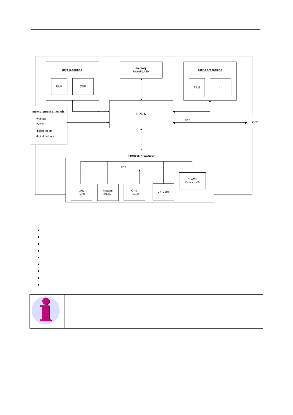
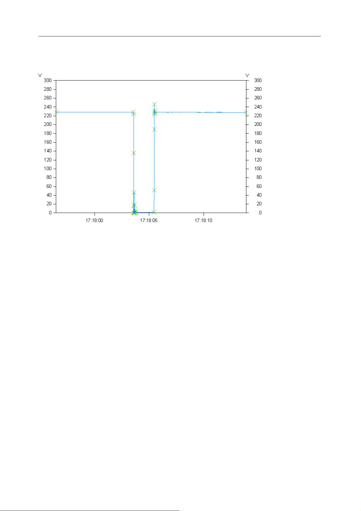
Fig 3-1 Curve plot of a voltage outage
3.2.3 Rapid fluctuations of the RMS-value
Rapid changes in the RMS-values of voltage and current are recorded in the curve plots. For this purpose, a
patented procedure called Transitional Recording is used.
The figure shows a voltage outage with data reduction. The crosses mark the sampled points of which the reduced
curve plot consists.
A "transition" always refers to a change from a stationary amplitude state to a new state, where state can also mean
a stretch of constant increase or decrease in amplitude. By comparing the slopes appearing within the curve to be
reduced, sudden changes of the curve's course can be detected. The procedure is designed to limit the resulting
curve plot's maximum deviation from the original signal.
The classic algorithm has been slightly modified for SICAM Q80 7KG8080. Thus, within a tolerance band of 5 %
around the nominal voltage, the algorithm works at its default accuracy of 1,5 %, while outside of this band it works at
twice that level, namely 0,75 %. The values can be edited via the user interface. As a result, events such as voltage
dips are represented in very high precision while within the uninteresting "passing" region, the data is strongly
reduced. By extending the data format to 64 bits the bufferable time range between two points is increased so that for
a constant voltage, an obligatory data point must be recorded only after approx. 23 hours.
These steps increase the achievable reduction factor al the way to 1:20,000 without sacrificing relevant information.
Ideally, if the network is free from disturbances, there would be eight data points per week: one per day plus the
initial point. By contrast, any disturbances are recorded with time resolution of one-half period. In any case: no
threshold values need to be set.
Power Quality Recorder SICAM Q80 7KG8080, System manual
E50417-H1076-C420-A2, Release 12.01.2015
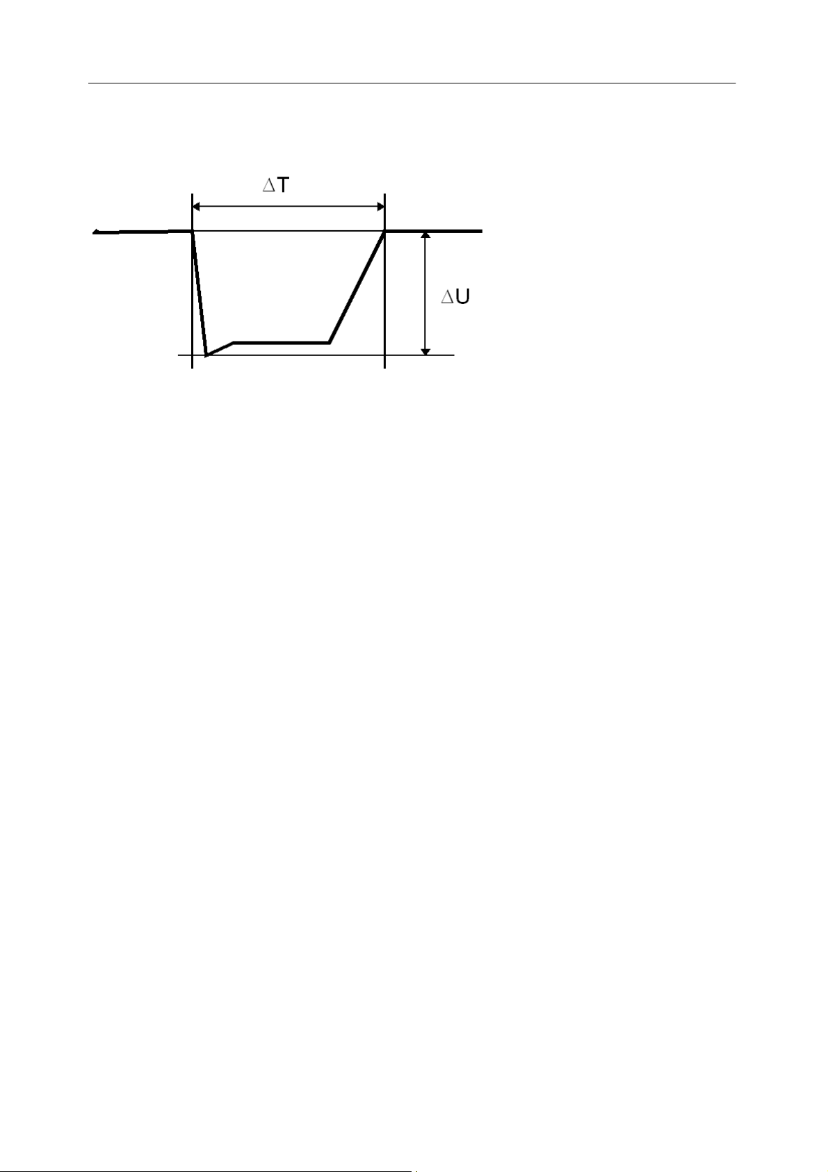
3.2.4 Events
Fig 3-2 Event with duration and magnitude
Typical courses of the voltage RMS-value which can be characterized by the duration and depth1 of the amplitude,
are recorded by SICAM Q80 7KG8080 as events.
The curve plots of the RMS-values serve as the source for the capture of events. While the deviation of the RMSvalue in one direction leads to the recording of a data point in a reduced curve plot, an event is always defined by
two transitions: one from the normal voltage level to the fault level one another one back to the normal level.
The duration of an event is measured between two departure points, in other words at the amplitude setpoint. The
magnitude of the event is determined from the minimum or maximum amplitude in the disturbance region. This is
done in the assumption that the amplitude remains relatively constant during the disturbance.
According to currently valid standards, every deviation of >10% form the nominal voltage counts as an event.
Depending on the duration and amplitude, distinctions are made between sags and outages.
1
For overvoltage, depth is the same as height.
15Introduction
3.2.5 Signal voltage (ripple control signals)
Signal voltage refers to a signal superimposed onto the supply voltage, which is used to communicate information.
The most familiar example is so-called ripple control signals.
SICAM Q80 7KG8080 has three special channels, each with different time resolution, for monitoring signal voltages.
1. In addition to the harmonics and interharmonics, the mean voltage level at signal frequency is also recorded.
2. The RMS-value of the spectral line of the FFT corresponding to the signal frequency is recorded with data
reduction.
Power Quality Recorder SICAM Q80 7KG8080, System manual
E50417-H1076-C420-A2, Release 12.01.2015
16 SICAM Q80 7KG8080
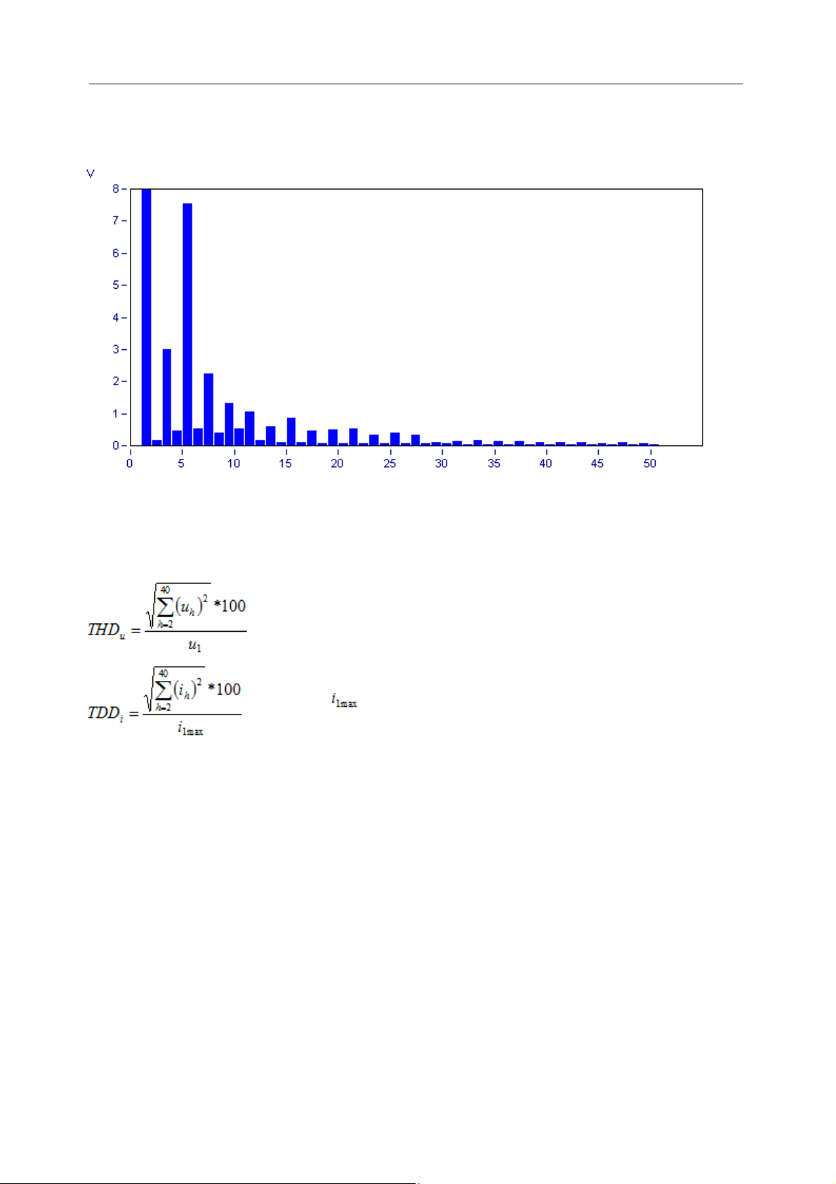
Fig 3-3 Mean values from FFT
Analogous to THD for current, in % of fundamental oscillation
with
= Maximum in the calculation interval
3.2.6 Harmonics, interharmonics
Calculation of the frequency components in voltages, currents and thus also in power is performed by means of a Fast
Fourier Transformation (FFT).
The FFT is computed with a rectangular window as per the standard EN 61000-4-7 "Specifications for the
measurement of harmonics and interharmonics in power supply networks". The harmonics are computed according to
the method of harmonics-subgroups, where the RMS value is determined with the two adjacent frequency lines.
The THD (total harmonic distortion) is determined according to the method of harmonics-subgroups total distortion.
This is the ratio of the RMS of the harmonics subgroups to the RMS of the fundamental oscillation subgroup.
The THD pertains to the fundamental oscillation. For this reason, even slightly distorted currents can yield a relatively
high THD, which is why with the TDD (Total Demand Distortion), the reference frame is not the mean of the
fundamental oscillation amplitude, but the maximum fundamental oscillation amplitude within the interval observed.
Thus, TDD <= THD. Since small currents only have minor effects on the overall system, the TDD is a better metric of
the burden from harmonic distortion.
This causes the number of samples to vary since it is chosen on the basis of the fundamental frequency in order to
calculate exactly the harmonic and interharmonic components of that particular fundamental. Example: According to
the standard, the frequency may deviate within the range 50 Hz ±1%. This means that for a 10 kHz sampling
frequency, a period can vary between 98..102 sample values.
The resulting frequency vector is used to derive the aggregation of the 50 harmonics and 10 interharmonics. Together
with the THD and signal voltage, 64 aggregations are derived for each input signal.
The spectra produced by the FFT can be viewed immediately by means of the online monitoring, for which purpose no
aggregation are computed. The special channel for the signal voltage recorded with data reduction (ripple control
signals) is fed directly from the FFT.
Power Quality Recorder SICAM Q80 7KG8080, System manual
E50417-H1076-C420-A2, Release 12.01.2015

4 QuickStart
"Task process" the tree diagram on the left side of the interface; according to
the selection made here; the right side displays corresponding options, data or
lists
o Select "New..."
o Select "Network settings..."
o "TCP/IP" must be selected
o Select "Network search"
o Select SICAM Q80 7KG8080
"Add device interface"-dialog appears
"Settings for network"-dialog appears
Close with "OK"
PC searches network for SICAM Q80 7KG8080 devices
Close with "OK"
Note
If your device doesn't appear in the list, you must first call "IF-Config" and assign the device a valid
address. (Start Menu/SICAM Q80 7KG8080/IF-Config; rf. “Configuring the Interface ").
Brief instructions on starting SICAM Q80 7KG8080 for the first time.
17QuickStart
4.1
Installation
Install the software
Connect measurement unit to the communication network
Connect measurement with all measurement leads (observe safety guidelines for dealing with high voltages!)
Switch on measurement unit. If you are commissioning multiple devices, switch on one at a time and assign the
IP-address.
Set IP address with program IF-Config (Start>program files>SICAM Q80 Manager>IF-Config).
o Click on the plus-sign by the network adapter in the left column
o Click on the plus-sign for your device
o Select the LAN branch
o Set the IP-address
Start the SICAM Q80 Manager program Prompt for device definition "OK"
Device selection dialog opens
The device selection dialog must be in the right-hand side list finish with "OK"
On the page Topology, right-click the mouse over the device and select New Parameter Set... the
Assistant opens.
(use the toolbar button or menu item "Parameter-Set / New Ctrl+N")
Enter a name for a new measurement site e.g. "Power Station 1"
Device is selected
Enter a name for the measurement task e.g. "Test 1"
Power Quality Recorder SICAM Q80 7KG8080, System manual
E50417-H1076-C420-A2, Release 12.01.2015
204
22
18 SICAM Q80 7KG8080
Complete the summary form by clicking
4.2
4.3
Making basic settings
The description for the measurment task opens 3-phase voltage measurement is selected,
or Task process/Network quality/Setup/Basic settings
Enter names for "Company", "Department",.. "Comment" …optional
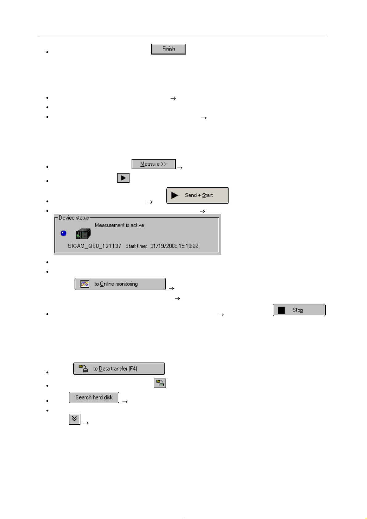
Measuring
Scroll down in the window, click the start dialog opens
or click on the toolbar key , or Task process/Measure/Start Stop network analysis
The device's current state is indicated click
The parameter are sent to the device. The device is started "Measurement is active"
You can now disconnect and exit the software; the device can continue measurement without the PC.
Or online monitoring of the measurement
4.4
o Click complete overview is displayed
o Task process / Measure / Standard display various data views can be selected
Return to Task process / Measure / Start Stop network analysis End measurement
(to obtain analyzable data, measurement should run at least 20 min)
Data transfer
Click on in the start dialog
or Task process / Data transfer or click in the toolbar
Select SICAM Q80 Manager searches the hard drive for saved measurements
Select a measurement and move it to the lower list
Select Measurement data are transferred and pre-processed
Power Quality Recorder SICAM Q80 7KG8080, System manual
E50417-H1076-C420-A2, Release 12.01.2015
19QuickStart
4.5
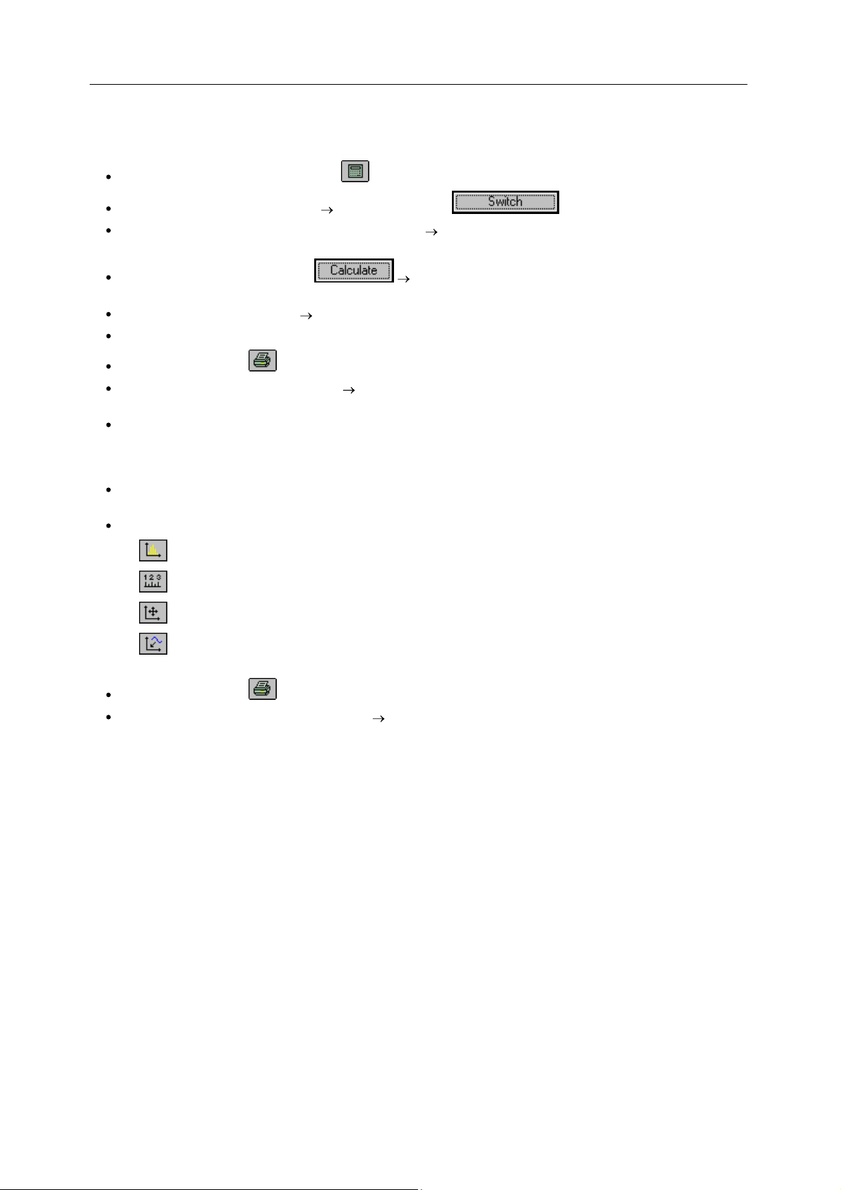
Evaluation
Go to analysis mode via toolbar button or Task process / Evaluation
Select a measurement from the list double-click or click
Task process / Evaluation / Network quality report opens the report dialog, with display measurement
settings and measurement duration
At the start of the evaluation, click Evaluation as per EN 50160 NV and MV or select other
value limits in Task process / Evaluation / Standard and limit values
Summary form appears filled in are there values which exceed standards limits?
Clicking on a bar in the overview chart, you go to the corresponding results table.
Use the toolbar button or menu item "Parameter-Set / Print.." to print out the report
Detailed observation of measured data under Task process / Evaluation, special overviews are available for
each type of measured data
E.g. Task process / Evaluation / Frequency displays
o table of all immediately displayable data,
o table of minimum and maximum values of the displayable data.
At the right edge of the window, there is a toolbar (the functions affect the data window selected, if more than
one window is open. A mouse-click on a window highlights it).
The available buttons are:
o Calculates histograms for the selected data
o Opens the dialog for Measuring/displaying data values
o Opens a data navigator (for moving through a long measurement data set)
o Opens the dialog Channel selection…, in order to be able to add any amount of additional channels to
the data window
Use the toolbar button or the menu item "Parameter-Set / Print.." to print out the data window
Menu item "Parameter-Set / Print preview" see effect of printout settings; make changes before printout, for
example, add comments…
Power Quality Recorder SICAM Q80 7KG8080, System manual
E50417-H1076-C420-A2, Release 12.01.2015
20 SICAM Q80 7KG8080
Loading a configuration
Displays overview of all configured measurement devices
Switch to measurement data analysis and Evaluation
5 Operation modes and settings
SICAM Q80 7KG8080 is able to performlong-term analysis. Long term analysis is accessed under the tree branch
Network quality and is the actual application complex which includes e.g. the standard EN50160 plus a few extras.
The task steps "Setup" and "Measurement" refer to the measurement task which was either just loaded or to be
processed. The other task steps use the current settings as defaults, but do not change the configuration.
5.1
Network quality
Loading a new measurement configuration / New start
Power Quality Recorder SICAM Q80 7KG8080, System manual
E50417-H1076-C420-A2, Release 12.01.2015
21
109
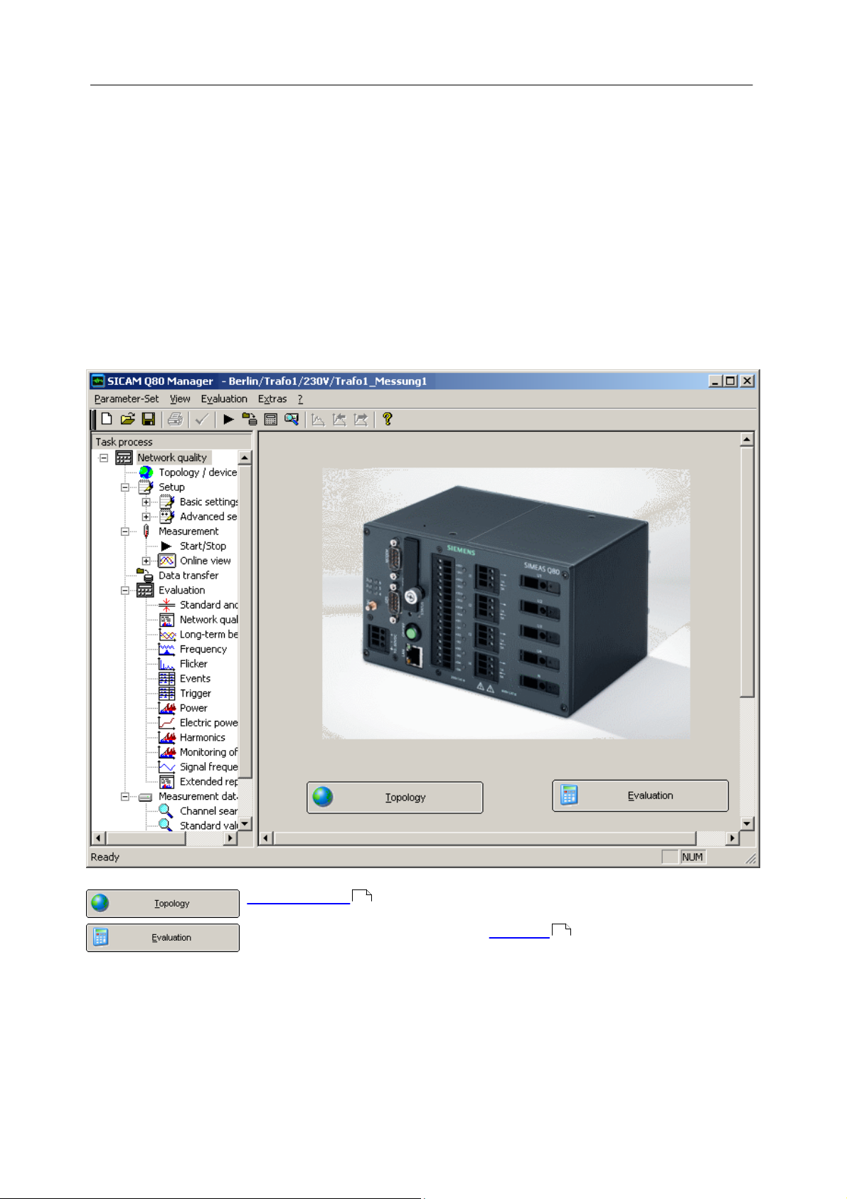
5.1.1 Topology / Devices
Total overview of all measurements
Device is active
Device is active and is being parameterized at present
21Operation modes and settings
The page Topology / Devices is the starting point for administering the measurements and device access.
The first steps are selection of the measurement devices and creation of the respective parameter set settings for
performing measurement.
In measurement operation, you are provided with an preview of the active measurement devices and the status of
every measurement running.
General procedure:
1. Make device definitions
2. Assign device in the topology
3. Create new parameter set or load an existing parameter set
4. Measure
Analysis
Variant 1
1. Load the last parameter set by means of the Device definition or using the Topology context menu item
Switch to analysis .
25
22
2. Go to the analysis. There, all concluded measured data for this parameter set are displayed.
Variant 2
Go to the analysis and use the Find... button to select a measurement location and data.
109
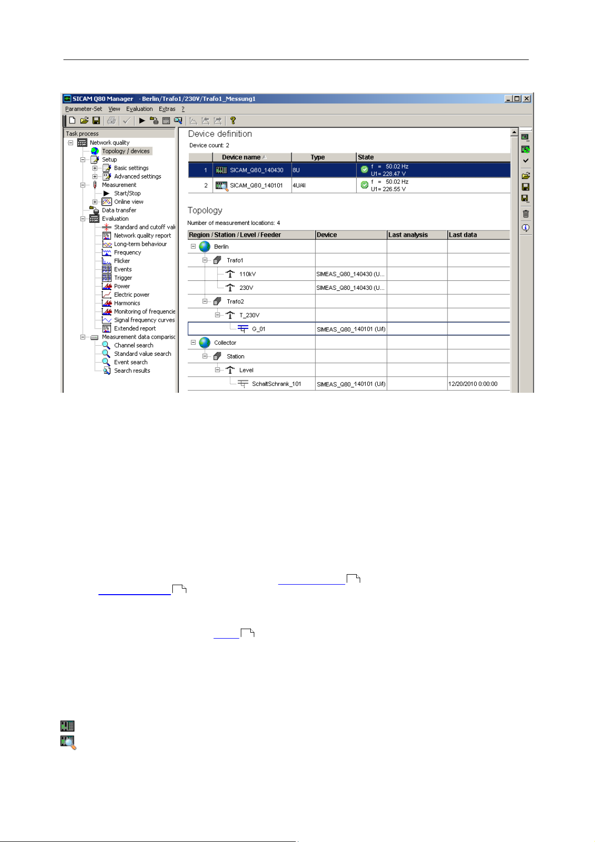
5.1.1.1 Device definition
The upper table shows all devices which have previously been used, and enables more devices to be added.
The device status is indicated by various symbols.
Power Quality Recorder SICAM Q80 7KG8080, System manual
E50417-H1076-C420-A2, Release 12.01.2015
22 SICAM Q80 7KG8080
Device is passive
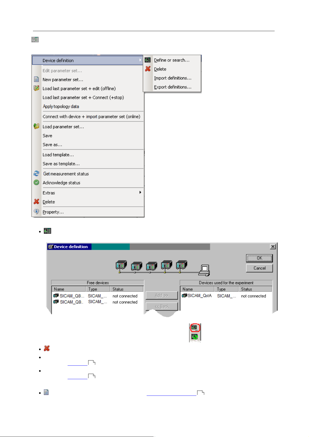
Device definition
Context menu
Device definition
Define or search...: Opens the device definition dialog, see also "Commissioning \ Connection to the
device" in the operating instructions.
Calling this function is also possible by means of the toolbar at right:
Delete: removes device from the table
Import definitions...: opens the selection dialog for specifying the folder from which to import device
definitions, see here.
24
Export definitions...: opens the selection dialog for specifying to which folder to save existing device
definitions, see here.
24
Parameter set
New parameter set...: Starts the Assistant for creating parameter sets . Only available when the device is
20
Power Quality Recorder SICAM Q80 7KG8080, System manual
E50417-H1076-C420-A2, Release 12.01.2015

23Operation modes and settings
23
active .
Load last parameter set + edit (offline): Loads the last edited parameter set. Here, no connection to the
device is established. The configuration can be changed while the measurement device is performing a
measurement. Only available while the device is active .
Load last parameter set + connect (+stop): Loads the last edited parameter set. Subsequently, the software
goes to the Start/Stop page and establishes a connection with the device. The running measurement is
63
automatically stopped. Only available while the device is active .
Apply topology data: Applies the device assignment from the topology. This is necessary if the topology
assignment was changed. In the program's title bar, the new assignment is displayed. Only available while the
device is active .
23
Connection with device + import parameter set (online): The system goes to the Start/Stop page . The
current parameters are imported from the device. This involves only a simple connection with the device in
order to import the parameters. Online values are not displayed as part of this action. For that purpose, the
Connect-command must be called! Only available while the device is active .
65 23
23
23
63
Load parameter set...: The dialog for selecting an arbitrary parameter set is displayed. The files are in the
format *.nqa, see also here . Only available while the device is active .
Save: Saves the current parameter set. Only available while the device is active .
20 23
23
Save as...: Saves the current settings under a new name for the parameter set. Only available while the device
is active .
23
Load template...: Loads a template by means of the selection dialog which appears. Only available while the
device is active .
23
Save as template...: Saves the current settings as a general template. A template amounts to a parameter set
without any fixed assignment to a device. Only available while the device is active .
23
Status of the measurement
Get measurement status: The system queries the current measurement status for frequency and voltage
U1. When the interface to the device is slow, only the frequency is queried. Only available while the device is
23
active .
Acknowledge status:: The entry returned by Get measurement status is deleted.
Extras:
Set as passive: The device is not used in this topology, see also here.
Activate: The device is used in this topology. Activation is also necessary so that other menu entries are
operable, see also here.
Conclude measurement data: Closes the current measured data in the device and makes them ready to be
retrieved, see also here.
Stop measurement: Stops the running measurement.
24
24
24
Update firmware...: Starts a firmware update. For this purpose, the running measurement is concluded. The
Autostart configuration is also deleted in the process, and is only generated again upon starting the new
measurement.
General
Delete: The selected entry (entries) and all associated sub-entries are deleted.
Properties: The properties of the selected topology entry, see here
26
Property
Following querying of the measurement state , the measurement device's properties are listed. This will include
21
the current IP-address as well as the time at which this address was determined. This allows you, among other
things, to check which address the device received via DHCP.
Power Quality Recorder SICAM Q80 7KG8080, System manual
E50417-H1076-C420-A2, Release 12.01.2015

24 SICAM Q80 7KG8080
Note
The measurement device count is limited to 99.
5.1.1.1.1 Import / Export of device definitions
In order to be able to define parameter sets offline, the measurement device's structure (amount and type of
measurement channels) must be known. For each device configured, then, a device definitions file (*.umi) is saved to
the PC.
If you create a parameter set for a device on a PC with which the device had never previously been connected, it is
possible to adopt its device definitions from a different PC.
Export: The definition files are saved in the specified folder.
Import: All measurement devices in the selected folder which are not yet known to the system are made known to the
PC.
5.1.1.1.2 Conclude measurement data
The smallest measurement interval is 30 min – shorted intervals are not generated. Repeated running of the
commend is acknowledged but no additional measurement intervals are generated.
The command can only be performed if no PC (except the one currently in use) is directly connected with the
device. If that is the case, there is a timeout error, since it is not possible to access the device for a specified
amount of time.
5.1.1.1.3 Active / Passive setting
Active enables access to devices.
If multiple devices are selected, many actions are only applied to active devices. Set any devices which are
switched off or not accessible as passive so that the measurement status query of all devices can be carried out
quickly. Otherwise, performing the command for inaccessible devices will cause significant delays.
5.1.1.1.4 Actions with the mouse
Selection of a device
In the topology, the measurement location at which this device is active is highlighted:
If the device is not active at any measurement location, the passive locations are displayed.
Double-clicking on the device name
The last configuration edited is loaded
Power Quality Recorder SICAM Q80 7KG8080, System manual
E50417-H1076-C420-A2, Release 12.01.2015
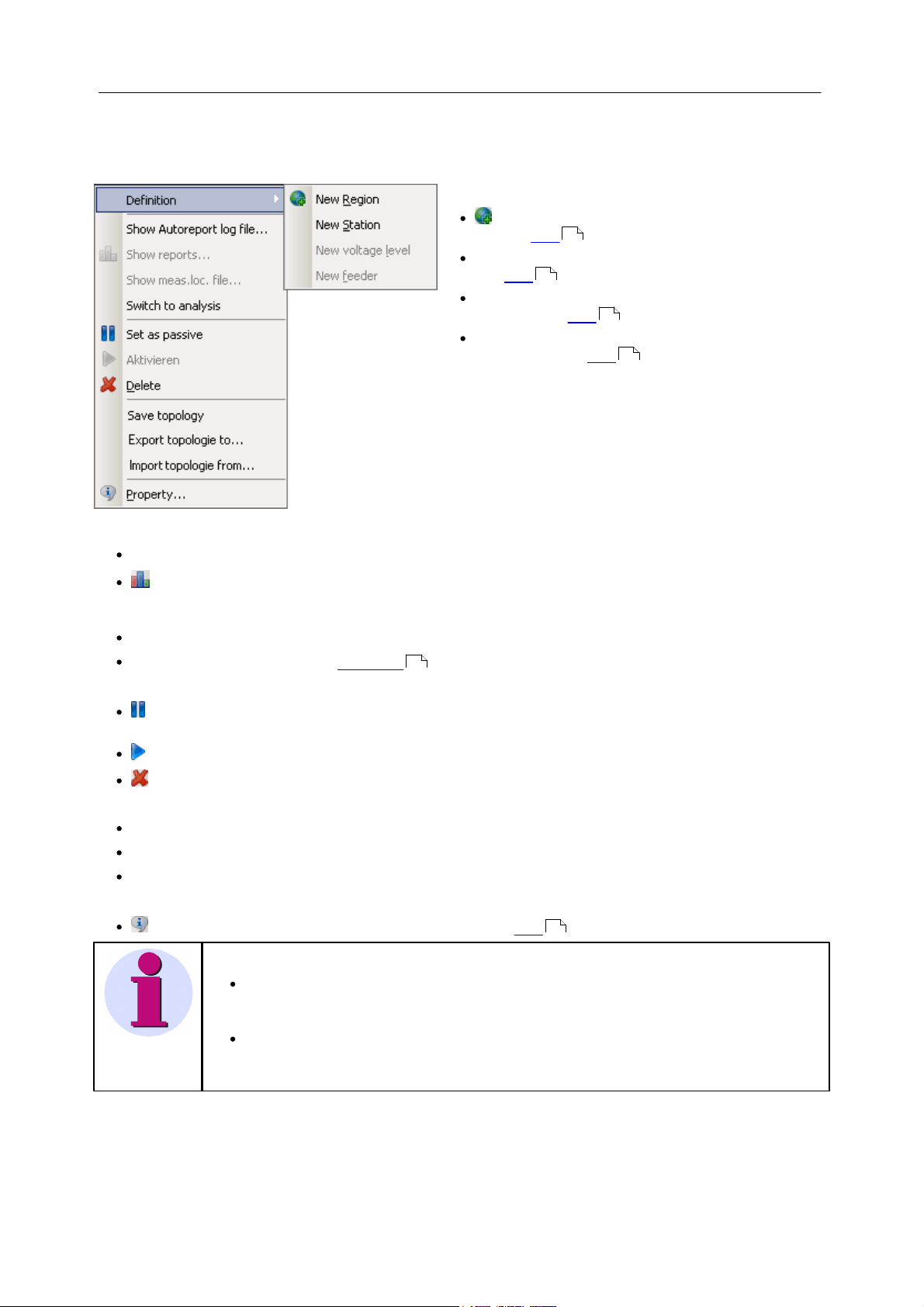
5.1.1.2 Topology
Definition: Creates new topology entries
New Region: Generates a new entry for a region,
see also here .
New Station: Generates a new entry for a station, see
also here .
New voltage level: Creates a new entry for a voltage
level, see also here .
New feeder: Generates a new entry for a measurement
location, see also here .
Note
When a device is parameterized, then this always refers to the current entries in the
topology. Thus, in the reports on a measurement location, different reports may be listed!
( e.g. due to exchanging devices, repairs etc.)
Any empty topology always shows the entries Collector \ Station \ Level. These are required
for storing data from unknown measurement locations for Autotransfer and -report purposes.
These entries can not be deleted.
The table below shows the topology and administers the measurement locations assignment of measured data.
Context menu
27
27
27
27
Report
Show Autoreport log file…: Shows general log file of the Autoreport (start time, when ended...)
25Operation modes and settings
Show reports...: Opens a selection dialog containing all reports. the reports are saved to the same older as
the parameter sets.
Default: <Public documents>\ SIEMENS\SICAMQ80\Data\<feeder>\<Parameter set>\<Reportx>.pdf
Show meas. loc. file...: Shows the measurement location's log file.
Switch to analysis: Goes to the Evaluation page .
Measurement location
Set as passive: Sets the measurement location to passive, in order that the device / measurement group is
assigned to another measurement location.
Activate: Activates the measurement location, on the condition that it is not already active at another branch.
Delete: Selected entry (entries) and all associated subentries are deleted.
Topology
Save topology: Saves the current topology
Export topology to...: Exports the current topology from an XML file.
Import topology from...: Imports a previously exported topology in XML format.
General
Properties: Properties of the selected topology entry, see here
109
26
Power Quality Recorder SICAM Q80 7KG8080, System manual
E50417-H1076-C420-A2, Release 12.01.2015
26 SICAM Q80 7KG8080
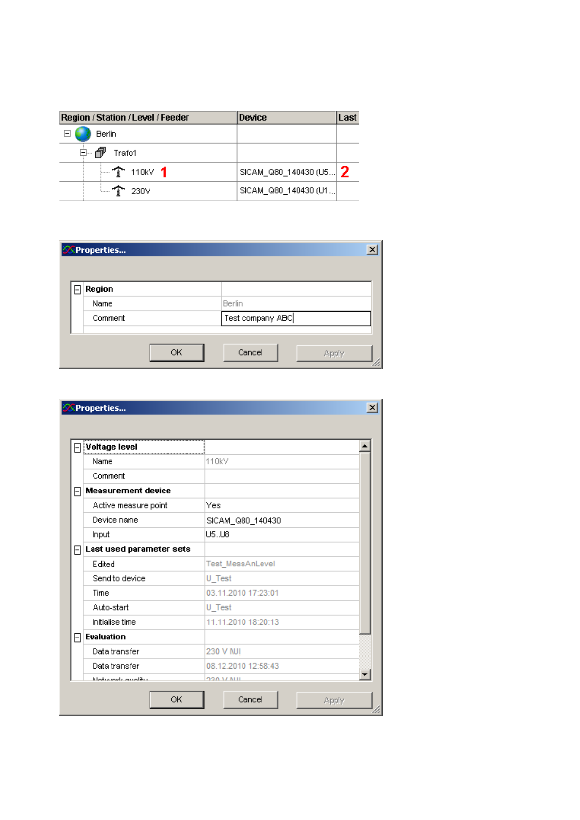
Excerpt from the topology. Selection of the properties by right-clicking in the
areas 1 or 2 leads to the subsequent properties dialogs
Properties context menu in the Region, Station, Voltage Level area
Properties context menu in the measurement location area
5.1.1.2.1 Properties of the topology objects
Depending on where in the program you right click for the context menu, selecting "Properties..." opens a variety of
dialogs:
1. Properties for Region, Station, Voltage Level
2. Also, for the measurement location
Power Quality Recorder SICAM Q80 7KG8080, System manual
E50417-H1076-C420-A2, Release 12.01.2015

Measurement device
Saves device list and topology
Saves the following current settings in a folder to be selected by the user (default folder = output
path)
Device list
the last parameter set edited for each device
Topology
The following subfolder is created in the selected folder:
<Date Time> TopologyExport
E.g. "2012-12-03 10_14_34 TopologyExport"
Loads device list and topology
Loads saved settings
selection of items to be loaded:
Device list – complete replacement or only loading of entries not present
Parameter sets (overwriting of configurations present)
Topology – complete replacement oror only loading of entries not present
o Active measure point: Activated in Topology
25
o Device name: Measurement device associated with the measurement location
o Input: Analog inputs. For devices having 8 voltage inputs: U1..U4; U5..U8, otherwise U/I
Last used parameter sets
o Edited: Name of the last parameter set edited
o Send to device: Name of the last parameter set sent.
o Time: Time of the last parameter set sent.
o Autostart: Last parameter set loaded as autostart
o Initialise time: Time of last parameter set loaded to the device as autostart.
Evaluation
o Data transfer: Name of the feeder and of the parameter set belonging to the last data transferred from the
device.
o Data transfer: Time of last transfer
o Network quality: Name of the branch and of the parameter set
o Measurement time: Start and end of the measurement
o Status: Indicates whether evaluation requirements are met: pass or fail
In normal operation, the names of the parameter sets shown here are all the same.
Differences appear when you have new parameter sets or if the measurement location was moved within the
topology.
27Operation modes and settings
5.1.1.2.2 Toolbar at right edge
The toolbar on the right edge enables saving and loading of the device list and topology:
5.1.1.2.3 Defining a new region, station or voltage level
In the context menu, the only entry ever active is the one which can be performed in conjunction with the current
selection. For example, for the station selected, only one new subordinate voltage level can be defined.
Power Quality Recorder SICAM Q80 7KG8080, System manual
E50417-H1076-C420-A2, Release 12.01.2015

28 SICAM Q80 7KG8080
5.1.1.2.4 Defining a new measurement location
Definable as a subentry for a voltage level or below the currently selected measurement location.
A device can only be assigned to an active measurement location! With devices having 2 voltage measurement
groups (8xU), assignment to 2 location is possible.
If a device is to alternate between different measurement locations, the old location must be set to passive .
5.1.1.2.5 Actions with the mouse
Double-click on the device name
This device is selected in the device list:
Double-click on the last evaluation
The list of reports is displayed in accordance with the context menu entry for Show reports .
25
25
Power Quality Recorder SICAM Q80 7KG8080, System manual
E50417-H1076-C420-A2, Release 12.01.2015

5.1.2 Setup
29Operation modes and settings
Use the mouse to fill in the boxes on the forms, which are later printed out. These forms provide the appearance of
"virtual paper"; see also Chapter Forms .
184
5.1.2.1 Parameter set
5.1.2.1.1 Open parameter set
Opening a parameter set: Select the menu item Parameter-set / Open or click on the Open symbol or select Load
parameter set... with a right click to the device at the Device definition.
A selection dialog appears.
21
By default, the parameter sets already defined are displayed for the branch circuit assigned to this device. (For this
reason, prior to this action the measurement must be assigned in the topology.) In the dialog shown, however, you
can also view and open parameter sets of other branches. After opening, the devices for which the parameter sets
were defined are activated. By saving these as templates, however, you can also assign them to another device.
Branch circuit 1
- ParameterSet11 (for device a)
- ParameterSet12 (for device a)
- ..
Branch circuit 2
- ParameterSet 21 (for device b)
- ParameterSet 22 (for device b)
- ..
Selected device: "Device a"
1. "Load a parameter set.." from "ParameterSet11"
2. The active device is "Device a"
Or:
1. "Load a parameter set.." from "ParameterSet21"
2. The active device is "Device b"
3. all further actions are performed with Device b.
Power Quality Recorder SICAM Q80 7KG8080, System manual
E50417-H1076-C420-A2, Release 12.01.2015
30 SICAM Q80 7KG8080
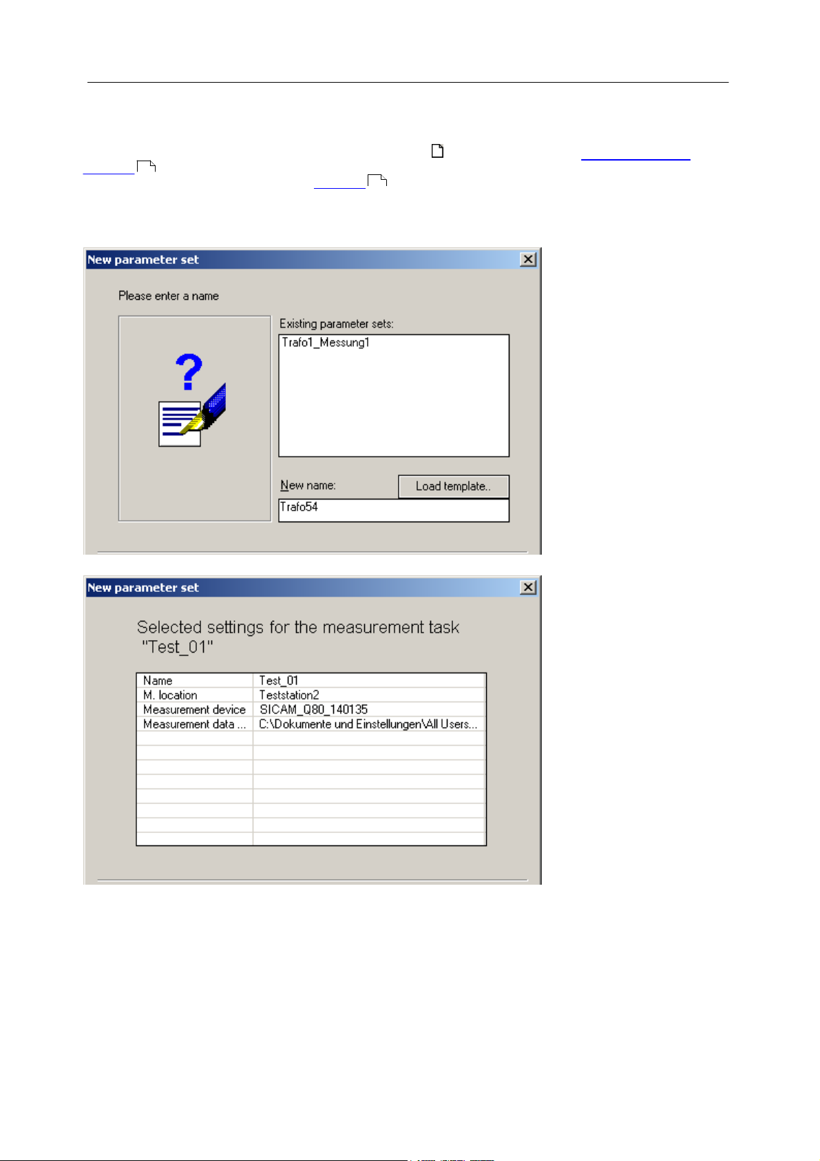
3. Entry of an name of the measurement task
4. Summary of entries
5.1.2.1.2 Create a parameter set
Creating a new parameter set
Select the menu item Parameter Set/ New, click on the symbol in the toolbar or use the context menu in the
Topology . To avoid name conflicts or errors in assigning measurement locations, it is recommended that you
create new measurement tasks using the Topology .
A wizard leads you through various dialogs for entering the required names and, if appropriate, for changing the data
storage location.
21
21
By clicking on Finish, a new configuration is created with the default settings.
If an existing measurement task is to be applied to a different measurement location and a different device:
a. Load the existing settings
b. Select Template/Save as...
c. Select another device
d. Open the saved template with Template / load...
e. Save as new parameter setThe storage of data is organized according to the following principle:
Power Quality Recorder SICAM Q80 7KG8080, System manual
E50417-H1076-C420-A2, Release 12.01.2015
 Loading...