

Page 1
Totally Integrated Power
Technical Series
Edition 3
Modeling of systems for Uninterruptible Power Supply (UPS) in SIMARIS®
design for application in data centers
siemens.com/tip-cs
Page 2

Technical Series Edition 3
Technical Series Edition 3
Modeling of systems for Uninterruptible Power Supply (UPS) in
SIMARIS® design for application in data centers
1. Basics
Uninterruptible power supply to the servers is of fundamental importance for data centers in order to have those
available 24hours a day and 365days a year. To achieve
this goal, the power supply must be thoroughly planned.
This includes the coordination between the components to
be used, taking into account that the selection and integration of UPS systems in the power supply concept is
essential in this process.
Meaning of the code elements:
AAA
The characteristic value describes the dependency of the UPS output supply in normal operation in case of change of voltage and fre-
quency at the input AC supply.
"VFD" (Voltage and Frequency Dependent):
UPS systems with VFD classification must pro-
tect the load against power failure.
In this case, the UPS output is influenced by
changes of the input AC voltage and the frequency, and it is not suitable for assuming
additional correction functions which may
arise from the application of an
autotransformer.
Characteristic values dependent on the voltage curve. A difference is made between
the following operating modes:
• Normal or bypass operation (first character)
• Energy storage operation (second character)
"S": The voltage curve is sinusoidal.
In case of linear and non-linear reference load (the exact specification can be found
in IEC62040-3), the total harmonic distortion is lower than 8%. The curve shape is
defined as sinusoidal.
"X": The curve shape is only sinusoidal in case of linear load. In case of non-linear refe-
rence load, the curve shape is no longer sinusoidal, as the total harmonic distortion
exceeds the limit value of 8%.
"Y": The voltage curve is not sinusoidal, neither for linear nor for non-linear reference
loads. The limit value of 8% is exceeded in both cases.
In accordance with the IEC 62040-3 standard
(DINEN62040-3; VDE0558 Part 530), UPS manufacturers
can designate their devices according to the classification
described therein. The assessment criteria are shown
hereafter as an excerpt:
Designation code: AAA BB CCC
i
e.g.: VFI SS 111 (highest classification)
BB
"VI" (Voltage Independent):
Like UPS systems with VFD, UPS systems with
VI classification must protect the load against
power failure, and also additionally ensure the
supply in case of
• undervoltage permanently applied to the
input
• overvoltage permanently applied to the
input.
The output of a UPS with VI classification
depends on the frequency of the AC voltage
input, and the output voltage must remain
within the prescribed limit voltage values.
"VFI" (Voltage and Frequency Dependent):
UPS systems with VFI classification are independent of (mains) supply voltage and frequency fluctuations, and must protect the load
against negative effects of such fluctuations
without discharging the energy storage
system.
CCC
Characteristic values for the dynamic behavior of the UPS output voltage:
• First numeral: in case of change of the operating mode
• Second numeral: in case of linear load step in normal or battery operation
(specification for the worst case)
• Third numeral: in case of non-linear load step in normal or battery operation
(specification for the worst case)
"1": required operating behavior for sensitive, critical loads.
The UPS output voltage remains within the limit values of curve 1 (see IEC62040-3)
in this section.
"2": permissible operating behavior for most of the critical loads.
The UPS output voltage remains within the limit values of curve 2 (see IEC62040-3)
in this section.
"3": permissible operating behavior for most of the general IT loads, e.g. switched-mode
power supplies.
The UPS output voltage remains within the limit values of curve 3 (see IEC62040-3)
in this section.
2
Page 3

Technical Series Edition 3
With SIMARIS design, electrical networks can be dimensioned with minimum input effort on the basis of real
products – from the medium-voltage level down to the
power consumer (which in the case of a data center means
down to the rack where the ICT equipment (ICT: Information and Communication Technology) is supplied with
power). This reduces your efforts for the overall planning
of the power distribution a lot, and thus the time for
selecting and dimensioning the electrical equipment –
with a high level of planning security.
When UPS systems are integrated for planning the power
distribution, the functionality is structured in SIMARIS
design, both
• as a load for selecting the components of the infeed
(transformers, generators, cables, busbars, switching
devices)
• and as a power source to depict the effects on the
downstream network regarding the maximum short-circuit currents in case of transformer infeed, as well as the
minimum short-circuit currents in case of inverter opera-
tion mode.
Following the standard EN 50600-2-2, Clause 6.3.2, the
functional elements of a power distribution system must
be selected in accordance with the selectivity and shortcircuit withstand strength requirements in all operating
modes and during different operating phases.
To supply the connected loads, the
• supply via the UPS
• supply via a UPS bypass
must be considered. Infeed takes places either through a
supply network (e.g. primary infeed for VFI operation and
secondary supply in case of internal bypass operation of
the UPS), or through an additional supply (e.g. generator).
With SIMARIS design it is possible to verify – for the downstream network – the compliance with the electrotechnical
conditions according to the standard, such as the switch-
off condition according to IEC60364-4-41 (DINVDE0100
Part410), as well as the selectivity.
3
Page 4
Technical Series Edition 3
2. Integration of UPS systems in power distribution networks
In power distribution networks, UPS systems are installed
to protect critical consumers for which an interruption of
the power supply or failures of the supply quality would
lead to serious consequences such as data loss, production
breakdown, or safety problems. The purpose of use usually
determines the functionality of a UPS, and thus the associ-
ated UPS classification. When the UPS is integrated in the
power distribution network, the functionality of the UPS
must be observed in order to avoid malfunctioning and
undesirable effects in case of fault or operational changes.
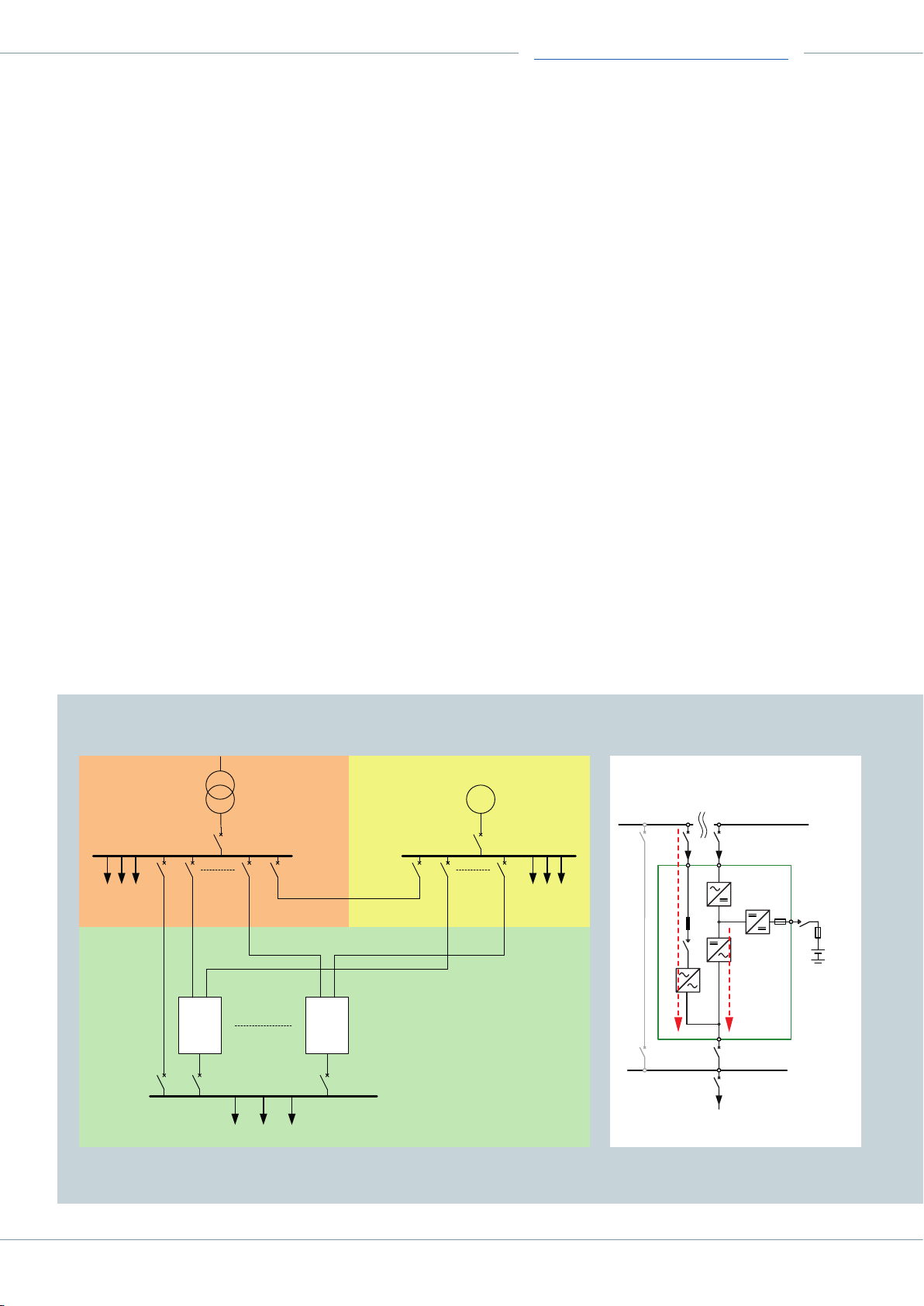
UPS systems with double instrument transformers (mostly
with UPS classification VFI) offer the maximum safety by
decoupling the load supply from the UPS input (see Fig.1),
and are taken as a basis for the following considerations.
The integration of a static UPS system in a concept for a
power supply network will be shown in the following by
means of a specific planning example, including the simu-
lation of the UPS in SIMARIS design.
Based on the assumption that the input for the static
bypass is supplied by the NPS busbar (transformer infeed,
low-voltage main distribution LVMD of the normal power
supply NPS) and the rectifier input is supplied by the SPS
busbar (generator, LVMD of the safety power supply SPS),
the resulting conditions from the perspective of the UPS
output side (main distribution SDUPS) are shown in a
simplified way in Fig.2.
The static bypass is supplied by the LVMDNPS (transformer). This considers the high short-circuit currents of a
transformer supply.
In double conversion operating mode, the UPS rectifier
supply through the LVMDSPS (generator) is decoupled
from the inverter output, which means that, in inverter
operation, the fault currents at the UPS output are exclusively determined by the inverter, and must be taken into
account in accordance with the manufacturer data.
Fig. 1: Integration of UPS systems with DC link (double conversion)
Normal
power supply
Normal loads
-
Manual bypass
Safety
power supply
UPS UPS
UPS
Fig. 2: Supply of a short circuit on the output side by the
transformer through the bypass or/and through the inverter
G
LVMD NPS LVMD SPS
Safety loads
Static bypass
Externeral manual bypass
Rectifier
Inverter
Load
Load
SD UPS
Battery
UPS loads
4
Page 5
3. Simulation of UPS systems in SIMARIS design
Technical Series Edition 3
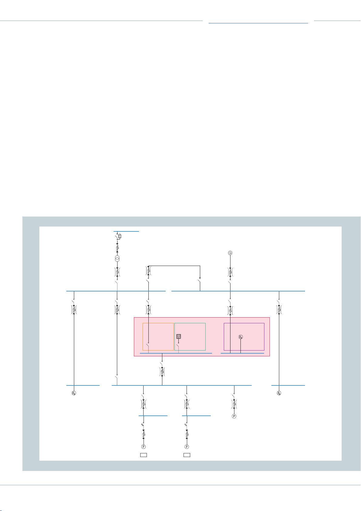
SIMARIS design offers various options for simulating UPS
systems, of which only the detailed simulation according
to Fig. 3 is represented. In this context, it must be
observed that the UPS function modes are simulated
together via SIMARIS design elements and the setting of
various operating modes.
In Fig. 3, the essential components required for the functionality of the UPS are identified by means of color boxes.
The red box marks the UPS as a symbol:
Yellow: Internal, static UPS bypass at one outgoing
circuit-breaker from the LVMDNPS to the UPS output
Green: Inverter as power source connected to the UPS
output
Dark red: Rectifier as load for rectifier supply and battery
charging at the incoming distribution from the generator
busbar
Fig. 3: Detailed simulation of UPS systems in SIMARIS design
MV-CB 5.1
Circuit-breaker
CB-f NAR
In (switch) = 630 A
Trans. current = 75/1A
7SJ8011
MV-C/L 5.1
N2XS2Y
5 m
XLPE 3 x 35
Transformer 1
Sn = 2,000 kVA / AN
ukr = 6 %
20/0.4 kV Dyn5
CB 31.1a
Circuit-breaker
In = 630 A
3VA24635HN320AA0/LSI
B 31.1
Busbar
50 m
BD2A-3-630
TN-S Un = 400 V
Load SD NPS
Dummy load
In = 451 A
Un = 400 V
3-pole
SD NPS
4GX63643E
S 1
Busbar
25 m
LI-AM32005H-55
LV-CB Transformer
Circuit-breaker
In = 3,200 A
3WL12402NG611AA2/LSING
External bypass CB 1
Circuit-breaker
In = 2,000 A
3WL11202EB611AA2/LSIN
S 1.1
Busbar
5 m
LI-AM20005H-55
External bypass CB 2
Circuit-breaker
In = 2,000 A
3WL11202EB611AA2/LSIN
LV-S 1
Busbar
5 m
LI-AM32005H-55
Coupling NPS/SPS
Circuit-breaker
In = 3.200 A
3WL12402NB711AA2/LSIN
LVMD NPS
TN-S Un = 400 V
Internal Bypass
Circuit-breaker
In = 2,500 A
3WL12322NB711AA2/LSING
S 1.2
Busbar
5 m
LI-AM25005H-55
Internal
bypass
Dummy bypass output
Circuit-breaker
In = 2,500 A
3WL12322NB711AA2/LSIN
UPS output
Circuit-breaker
In = 2,000 A
3WL11202EG711AA2/LSING
S 3
Busbar
5 m
LI-AM20005H-55
UPS CB 1
Circuit breaker - 3VA with ELISA characteristics
In = 630 A
3VA24635HK320AA0/LI
S 24.1
Busbar
25 m
BD2A-3-630
UPS load 1
TN-S Un = 400 V
Fu-SD 24.2a
Fuse Switch Disc.
In = 300 A
3 x 3NA3250 Size 2
3NJ41333BF01 Size 2
C/L 24.2
Cable/line
25 m
Cu 1(3x240/240/120)
Total load 1
Inner zone
In = 241 A
Un = 400 V
3+N-pole
Remark: Regarding the rectifier requirements, not only the
battery charging, but also the UPS losses in operation must
be considered.
Moreover, Fig. 3 shows the three types of power supply via
the corresponding sub-distributions:
• Normal power supply NPS (sub-distribution SDNPS)
• Safety power supply SPS (sub-distribution SDSPS)
• Uninterruptible power supply (sub-distribution SDUPS)
In addition, Fig. 3 shows a comparison between a molded-
case circuit-breaker 3VA with the ELISA tripping unit and a
3VA circuit-breaker with an LSI tripping unit at the UPS
sub-distribution. The advantages of adjusting the ELISA
tripping characteristic to the one of a fuse are suggested.
The example can also be found in the enclosed SIMARIS
design file. Please contact your TIP partner at Siemens for
more information.
Generator 1
Pn = 1,800 kW
Sn = 2,250 kVA
Un = 400 V
S 2
Busbar
10 m
NPS/SPS SD
Non-automatic CB
In = 2,500 A
3WL12252AA711AA2
UPS OUT
TN-S Un = 400 V
UPS load 2
TN-S Un = 400 V
UPS
Inverter Rectifier input &
UPS inverter output
In = 1,732 A
Un = 400 V
Dummy inv. output
Circuit-breaker
In = 2,500 A
3WL12252NG711AA2/LSING
UPS CB 2
Circuit-breaker - 3VA with LSI characteristics
In = 800 A
3VA25805KQ320AA0/LSIG
S 29.2
Busbar
25 m
BD2A-3-800
Fu-SD 29.2a
Fuse Switch Disc.
In = 300 A
3 x 3NA3250 Size 2
3NJ41333BF01 Size 2
C/L 29.2
Cable/line
25 m
Cu 1(3x240/240/120)
Total load 2
Inner zone
In = 241 A
Un = 400 V
3+N-pole
2x2x
LI-AM40005H-55
Generator switch
Circuit-breaker
In = 4,000 A
3WL12402NG711AA2/LSING
Output switch to rectifier
Circuit-breaker
In = 2.500 A
3WL12322NG711AA2/LSING
S 2.1
Busbar
5 m
LI-AM25005H-55
battery charging
Rectifier + Battery
Inner zone
In = 1,890 A
Un = 400 V
3-pole
TN-S Un = 400 V
SD UPS
TN-S Un = 400 V
UPS CB 3
Circuit-breaker
In = 630 A
3VA24635HN320AA0/LSI
S 4.2
Busbar
10 m
BD2A-3-630
Total load 3
Inner zone
In = 577 A
Un = 400 V
3+N-pole
LVMD SPS
TN-S Un = 400 V
CB 30.1a
Circuit-breaker
In = 400 A
3VA23405HN320AA0/LSI
B 30.1
Busbar
25 m
BD2A-3-400
UPS IN
SD SPS
TN-S Un = 400 V
Load SD SPS
Dummy load
In = 271 A
Un = 400 V
3-pole
5
Page 6
Technical Series Edition 3
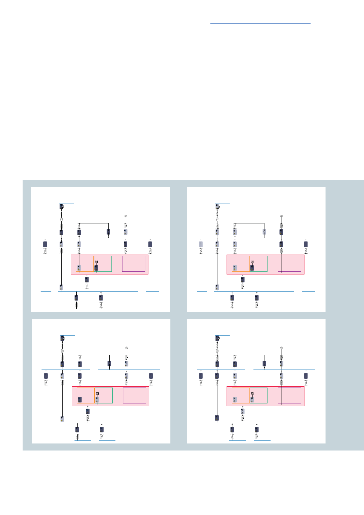
For the different functionalities of the UPS, individual
operating modes can be defined and calculated in SIMARIS
design (Fig. 4):
• Normal UPS operation VFI ①:
Double conversion operating mode of the UPS via rectifier and inverter fed by the transformer
• Normal UPS operation VFI via generator ②:
• Internal bypass operation of the UPS ③:
The rectifier and inverter of the UPS are bypassed; the
UPS sub-distribution MDUPS is supplied through the
transformer
• External bypass operation for UPS service purposes ④:
The UPS is isolated and all loads are supplied through the
transformer.
Double conversion operating mode of the UPS via rectifier and inverter fed by the generator
Fig. 4: Functional UPS simulation by determination of operating modes in SIMARIS design
Operating mode ①: UPS in VFI double conversion operating
mode, infeed from transformer
Operating mode ②: UPS in VFI double conversion operating
mode, infeed from generator
Internal
bypass
UPS
Inverter Rectifier &
battery loading
Operating mode ③: Internal bypass operation,
infeed from transformer
Internal
bypass
UPS
Inverter Rectifier &
battery loading
Internal
bypass
UPS
Inverter Rectifier &
battery loading
Operating mode ④: External bypass operation,
infeed from transformer
Internal
bypass
UPS
Inverter Rectifier &
battery loading
6
Page 7
Technical Series Edition 3
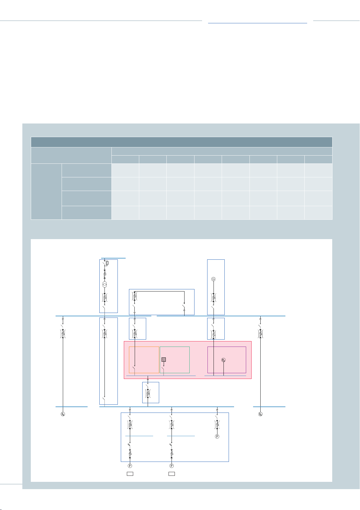
To illustrate the correlations between the operating modes
and the calculations in SIMARIS design, the different
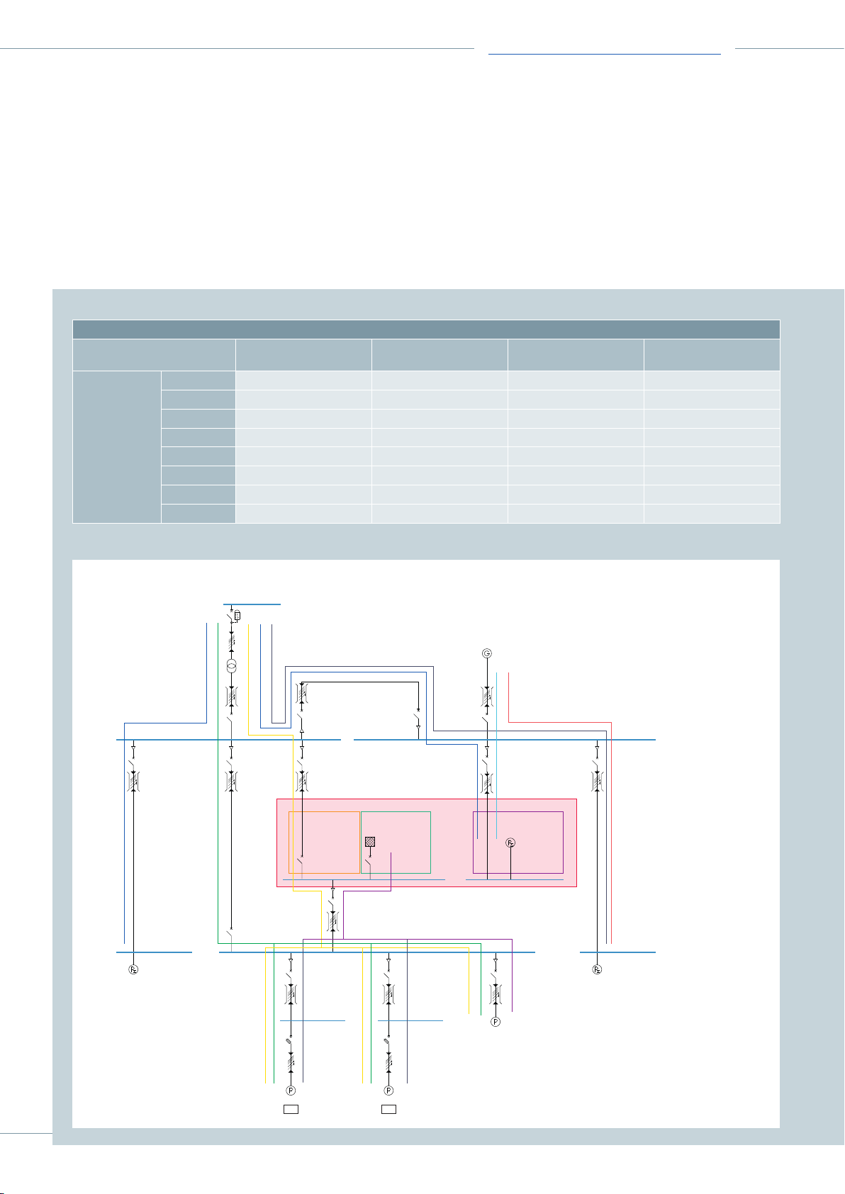
operating modes are itemized in Tab. 1 and Tab. 2:
• Tab. 1 shows the relevant circuits for dimensioning in the
• Tab. 2 shows the current paths for determining the
selectivity and the switch-off conditions, and assigns
them to the respective operating modes (illustration in
Fig. 6).
respective operating mode (illustration in Fig. 5)
Tab. 1: Observance of operating mode determination when dimensioning with SIMARIS design
Dimensioning of products and systems (x identies operating modes to be considered during dimensioning)
Circuit (see Fig. 5)
① ② ③ ④ ⑤ ⑥ ⑦ ⑧
Operating
mode
UPS VFI operation via
transformer
UPS VFI operation via
generator
Internal bypass
operation
External bypass
operation
Fig. 5: Illustration of circuits for dimensioning during UPS simulation
x x x x x
x x x x
x x x x x
x x x x
①
②
④ ⑤ ⑥
Internal
bypass
Inverter Rectifier &
⑦
UPS
① Transformer infeed
③
② NPS-SPS coupling
③ Generator infeed
④ External bypass
⑤ Feeder to internal bypass of UPS
⑥ Feeder to UPS rectifier
⑦ UPS output feeder
⑧ UPS distribution
battery charging
⑧
2x2x
7
Page 8
Technical Series Edition 3
Tab. 2: Observance of operating mode determination for considerations of selectivity and switch-o conditions with SIMARIS design
Selectivity and switch-o conditions (x identies current paths to be observed)
Current paths
(see Fig. 6)
UPS VFI operation via
transformer
① x x x
② x
③ x
④ x
⑤ x x x
⑥ x
⑦ x
⑧ x x
UPS VFI operation via
generator
Internal bypass operation External bypass
operation
Fig. 6: Illustration of current paths for considerations of selectivity and switch-o conditions during UPS simulation
Transformer infeed - NPS distribution
①② ③④⑤
Internal
bypass
Inverter Rectifier &
⑧
UPS
①
② Transformer infeed - external bypass - UPS distribution
③ Transformer infeed - internal bypass - UPS distribution
④ Transformer infeed - NPS-SPS coupling - Rectifier infeed
⑤ Transformer infeed - NPS-SPS coupling - SPS distribution
⑥ ⑦
⑥ Generator infeed - Rectifier infeed
⑦ Generator infeed - SPS distribution
⑧ Inverter infeed - UPS distribution
battery charging
2x2x
8
Page 9

Technical Series Edition 3
4. Technical UPS data for simulation in SIMARIS design
For the example shown in here, manufacturer information
for a specific UPS with an apparent power of 1,200kVA
was taken as a basis (see Tab. 3).
Tab. 3: Technical data for the example UPS1) (used in the enclosed SIMARIS design le)
Rated value of the apparent power in kVA 1,200
Rated active power in kW 1,200
Rated voltage in V 400 (380/415 selectable, 3ph + N)
Rated frequency in Hz 50 (60 selectable)
Rated output current in A 1,731
Maximum input current in A 1,890
Maximum short-circuit current (short-circuit withstand strength of
the UPS) in A
Minimum short-circuit current (overload capability of the UPS2)) in A 2,597
1) The UPS dat a corresponds to a L iebert® Trin ergy™ Cube of Ver tiv™ with an appa rent power of 1,200kVA
2) Informat ion of Vertiv™: 150 % ove rload at rated ou tput voltage for 1 m in
3,877
5. Critical issues regarding the integration of UPS systems
in power supply networks
Regardless of the simulation of a UPS in SIMARIS design,
the following issues must be especially observed when
integrating UPS systems in power supply networks:
• Faults on the SDUPS are critical and must be avoided
preventively – using high-quality components (busbar
trunking systems including design verified connection;
SIVACONS8 in rootless design, ...)
• In inverter operation, faults on the SDUPS can be a
problem for switching off according to IEC60364-4-41
(DINVDE0100 Part410) if the fault currents are almost
as high as the rated currents. In case of 1-pole faults to
earth, high-quality circuit-breakers with G releases (e.g.
Siemens 3WL circuit-breakers with ETU45B, ETU76B and
3VA circuit-breakers with ETU550/560, ETU 850/860) can
be the solution
• When switching off according to IEC60364-4-43
(DINVDE0100 Part430) and in order to implement
selectivity, it is advisable – due to the UPS short-circuit
behavior – to limit the rated currents of the switching
devices in the outgoing feeders of the SDUPS to 30% of
the UPS rated output current
6. Sample file for SIMARIS design
• For low-range UPS systems (<100kVA), RCDs can
be used for 1-pole faults to earth. In case of unfavorable
design of the SDUPS, an optimized calculation of the
minimum short-circuit currents under consideration of
the regular UPS behavior can be an advantage for the
design
• In case of short circuit at the UPS output, the permissible
load of the static bypass must be compared with the
information of the UPS manufacturer
• If the UPS manufacturer uses a a semiconductor fuse for
protecting the static bypass, this must be observed in the
selectivity considerations
• When integrating the UPS systems in a TN-S system, the
central earthing point and the number of poles of the
switching devices (3- or 4-pole) must be defined, among
others
• In case of UPS systems connected in parallel, a fault
analysis in the downstream distribution network can
reveal a possible additional protection requirement.
Enclosed with the document you will find the SIMARIS
design model network (.sdx) with a static UPS system for
integration in your own projects. The file has been created
with SIMARIS design10.
Further information as well as the SIMARIS suite, which
allows you to access planning tools such as SIMARIS design
10, can be found at
siemens.com/simaris.
9
Page 10

Imprint
Published by: Siemens AG
Smart Infrastructure
Distribution Systems
Mozartstr. 31 c
91052 Erlangen, Germany
E-mail: [email protected]
For the U.S. published by
Siemens Industry Inc.
100 Technology Drive
Alpharetta, GA 30005
United States
Subject to change without prior notice • 10/20
© Siemens 2020 • All rights reserved
Subject to changes and errors. The information given in this
document only contains general descriptions and/or perfor-
mance features which may not always specifically reflect
those described, or which may undergo modification in the
course of further development of the products. The
requested performance features are binding only when
they are expressly agreed upon in the concluded contract.
SIMARIS® is a registered trademark of Siemens AG. Any
unauthorized use is prohibited. All other designations in
this document may represent trademarks whose use by
third parties for their own purposes may violate the proprie-
tary rights of the owner.
 Loading...