

Siemens SICAM Q100 7KG95 Series Manual

Class A Power Quality
Instrument and
Power Monitoring Device
SICAM Q100
7KG95xx
Preface
Open Source Software
Contents
User Information 1
Overview 2
Device Design 3
Measured Quantities and Recording 4
Energy Management 5
Security 6
V2.10
Device Manual
Getting Started 7
Connection Principle 8
Operation at Use of a PC 9
Operation at Use of the Display 10
Time Synchronization 11
Maintenance, Storage, Transport 12
Failures and LED Indications 13
Technical Data 14
Operational Indications 15
Operating Parameters 16
Glossary
E50417-H1040-C522-A6
Appendix
Index

NOTE
For your own safety, observe the warnings and safety instructions contained in this document, if available.
Disclaimer of Liability
This document has been subjected to rigorous technical review
before being published. It is revised at regular intervals, and any
modifications and amendments are included in the subsequent
issues. The content of this document has been compiled for
information purposes only. Although Siemens AG has made best
efforts to keep the document as precise and up-to-date as possible,
Siemens AG shall not assume any liability for defects and damage
which result through use of the information contained herein.
This content does not form part of a contract or of business
relations; nor does it change these. All obligations of Siemens AG
are stated in the relevant contractual agreements.
Siemens AG reserves the right to revise this document from time to
time.
Document version: E50417-H1040-C522-A6.05
Edition 06.2019
Version of the product described: V2.10
Copyright
Copyright Siemens AG 2019. All rights reserved.
The disclosure, duplication, distribution and editing of this
document, or utilization and communication of the content are not
permitted, unless authorized in writing. All rights, including rights
created by patent grant or registration of a utility model or a design,
are reserved.
Registered Trademarks
SIPROTEC
SIEMENS AG. An unauthorized use is illegal.
All other designations in this document can be trademarks whose
use by third parties for their own purposes can infringe the rights of
the owner.
TM
and SICAMTM are registered trademarks of

Preface
Purpose of this Manual
This manual describes the application, functions, installation, commissioning, and operation of the Class A
Power Quality Instrument and Power Monitoring Device SICAM Q100 7KG95xx.
Target Group
This manual is intended for project engineers, commissioning and operating personnel in electrical systems
and power plants.
Scope of Validity of this Manual
This manual is valid for the Class A Power Quality Instrument and Power Monitoring Device SICAM Q100
7KG95xx.
Further Support
For any questions concerning your system, please contact your Siemens representative.
The Siemens Customer Support Center provides around-the-clock support.
Phone: +49 (180) 524-7000
Fax: +49 (180) 524-2471
Internet: www.siemens.com/powerquality
e-mail: support.energy@siemens.com
Training Courses
If you are interested in our current training program, please contact our training center:
Siemens AG
Siemens Power Academy TD
Humboldtstr. 59
D-90459 Nuremberg
Tel.: +49 (911) 433-7415
Fax: +49 (911) 433-7929
Internet: https://www.siemens.com/poweracademy
e-mail: poweracademy@siemens.com
E50417-H1040-C522-A6, Edition 06.2019
3SICAM Q100, 7KG95xx, Device Manual
Notes On Safety
This manual is not a complete index of all safety measures required for operation of the equipment (module,
device). However, it comprises important information that must be noted for purposes of personal safety, as
well as in order to avoid material damage. Information is highlighted and illustrated as follows according to the
degree of danger.
DANGER
DANGER means that death or severe injury will occur if the appropriate safety measures are not taken.
✧ Follow all advice instructions to prevent death or severe injury.
WARNING
WARNING means that death or severe injury can occur if the appropriate safety measures are not taken.
✧ Follow all advice instructions to prevent death or severe injury.
CAUTION
CAUTION means that minor or moderate injury can occur if the appropriate safety measures are not taken.
✧ Follow all advice instructions to prevent minor injury.
NOTICE
NOTICE means that damage to property can occur if the appropriate safety measures are not taken.
✧ Follow all advice instructions to prevent damage to property.
NOTE
is important information about the product, the handling of the product, or the part of the documentation in
question to which special attention must be paid.
4 SICAM Q100, 7KG95xx, Device Manual
E50417-H1040-C522-A6, Edition 06.2019

Personnel Qualified in Electrical Engineering
Only qualified electrical engineering personnel may commission and operate the equipment (module, device)
described in this document. Qualified electrical engineering personnel in the sense of this manual are people
who can demonstrate technical qualifications as electrical technicians. These persons may commission, isolate, ground, and label devices, systems and circuits according to the standards of safety engineering.
Use as Prescribed
The equipment (device, module) must not be used for any other purposes than those described in the Catalog
and the Technical Description. If it is used together with third-party devices and components, these must be
recommended or approved by Siemens.
If the device is not used in accordance with the Product Information and this manual, the scheduled protection
is impaired.
Problem-free and safe operation of the product depends on the following:
• Proper transport
• Proper storage, setup, and installation
• Proper operation and maintenance
When electrical equipment is operated, hazardous voltages are inevitably present in certain parts. If proper action is not taken, death, severe injury, or property damage can result.
• The equipment must be grounded at the grounding terminal before any connections are made.
• All circuit components connected to the power supply may be subject to dangerous voltage.
• Hazardous voltages may be present in equipment even after the supply voltage has been disconnected
(capacitors can still be charged).
• Equipment with exposed current transformer circuits must not be operated. Prior to disconnecting the
equipment, ensure that the current transformer circuits are short-circuited.
• The limit values stated in the document may not be exceeded. This must also be considered during testing
and commissioning.
E50417-H1040-C522-A6, Edition 06.2019
5SICAM Q100, 7KG95xx, Device Manual
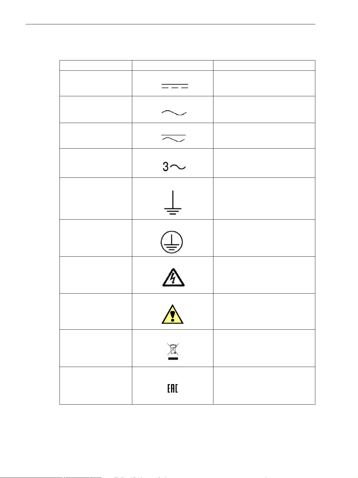
Used Symbols
No. Symbol Description
1 Direct current
IEC 60417-5031
2 Alternating current
IEC 60417-5032
3 Direct and alternating current
IEC 60417-5033
4 Three-phase alternating current
5 Earth (ground) terminal
IEC 60417-5017
6 Protective conductor terminal
IEC 60417-5019
7 Caution, risk of electric shock
8 Caution, risk of danger
ISO 7000-0434
9
Guideline 2002/96/EC for electrical and
electronic devices
10
Guideline for the Eurasian Market
6 SICAM Q100, 7KG95xx, Device Manual
E50417-H1040-C522-A6, Edition 06.2019
Statement of Conformity
This product complies with the directive of the Council of the European Communities on the
approximation of the laws of the Member States relating to electromagnetic compatibility (EMC
Council Directive 2004/108/EC - valid until April 19th, 2016; EMC Council Directive 2014/30/EU valid as of April 19th, 2016) and concerning electrical equipment for use within specified voltage
limits (Lowvoltage Directive 2006/95/EC - valid until April 19th, 2016; Lowvoltage Directive 2014/35/
EU - valid as of April 20th, 2016).
This conformity has been established by means of tests conducted by Siemens AG according to the
Council Directive in agreement with the generic standards EN 61000-6-2 and EN 61000-6-4 for the
EMC directives, and with the standard EN 61010-1 for the low-voltage directive.
The device has been designed and produced for industrial use.
The product conforms to the standard IEC 62586-1, Ed. 1.
Further Standards
This product is UL-certified to Standard UL 61010-1, third edition, based on the specification stated in Chapter 14
(Technical Data).
UL File No.: E228586
Open-type Measuring Equipment
2UD1
For further information see UL database on the internet: https://ul.com.
Choose Online Certifications Directory and insert E228586 under UL File Number.
E50417-H1040-C522-A6, Edition 06.2019
7SICAM Q100, 7KG95xx, Device Manual

8 SICAM Q100, 7KG95xx, Device Manual
E50417-H1040-C522-A6, Edition 06.2019

Open Source Software
The product contains, among other things, Open Source Software developed by third parties. The Open
Source Software used in the product and the license agreements concerning this software can be found in the
Readme_OSS.
These Open Source Software files are protected by copyright. Your compliance with those license conditions
will entitle you to use the Open Source Software as foreseen in the relevant license. In the event of conflicts
between Siemens license conditions and the Open Source Software license conditions, the Open Source Software conditions shall prevail with respect to the Open Source Software portions of the software.
The Open Source Software is licensed royalty-free. Insofar as the applicable Open Source Software License
Conditions provide for it, you can order the source code of the Open Source Software from your Siemens sales
contact - against payment of the shipping and handling charges - for a period of at least 3 years since purchase
of the Product. We are liable for the Product including the Open Source Software contained in it pursuant to
the license conditions applicable to the Product. Any liability for the Open Source Software beyond the program
flow intended for the Product is explicitly excluded. Furthermore any liability for defects resulting from modifications to the Open Source Software by you or third parties is excluded. We do not provide any technical support for the Product if it has been modified.
NOTE
To read the Readme_OSS file, a PDF viewer must be installed on the computer.
E50417-H1040-C522-A6, Edition 06.2019
9SICAM Q100, 7KG95xx, Device Manual

10 SICAM Q100, 7KG95xx, Device Manual
E50417-H1040-C522-A6, Edition 06.2019

Contents
Preface . . . . . . . . . . . . . . . . . . . . . . . . . . . . . . . . . . . . . . . . . . . . . . . . . . . . . . . . . . . . . . . . . . . . . . . . . . . . . . . . . . 3
Open Source Software . . . . . . . . . . . . . . . . . . . . . . . . . . . . . . . . . . . . . . . . . . . . . . . . . . . . . . . . . . . . . . . . . . . . . 9
1 User Information . . . . . . . . . . . . . . . . . . . . . . . . . . . . . . . . . . . . . . . . . . . . . . . . . . . . . . . . . . . . . . . . . . . . . . . . . 17
2 Overview. . . . . . . . . . . . . . . . . . . . . . . . . . . . . . . . . . . . . . . . . . . . . . . . . . . . . . . . . . . . . . . . . . . . . . . . . . . . . . . . 19
2.1 Device Versions . . . . . . . . . . . . . . . . . . . . . . . . . . . . . . . . . . . . . . . . . . . . . . . . . . . . . . . . . . . . . . . . . . 20
2.2 Ordering Information, Scope of Delivery and Accessories . . . . . . . . . . . . . . . . . . . . . . . . . . . . . . . . . . 22
3 Device Design . . . . . . . . . . . . . . . . . . . . . . . . . . . . . . . . . . . . . . . . . . . . . . . . . . . . . . . . . . . . . . . . . . . . . . . . . . . 25
3.1 Mechanical Design . . . . . . . . . . . . . . . . . . . . . . . . . . . . . . . . . . . . . . . . . . . . . . . . . . . . . . . . . . . . . . . . 26
3.2 Display and Softkeys . . . . . . . . . . . . . . . . . . . . . . . . . . . . . . . . . . . . . . . . . . . . . . . . . . . . . . . . . . . . . . 27
3.3 Terminal Diagram of the Back Plate . . . . . . . . . . . . . . . . . . . . . . . . . . . . . . . . . . . . . . . . . . . . . . . . . . . 28
4 Measured Quantities and Recording . . . . . . . . . . . . . . . . . . . . . . . . . . . . . . . . . . . . . . . . . . . . . . . . . . . . . . . . . 29
4.1 Power Quality Measuring System and Recording System . . . . . . . . . . . . . . . . . . . . . . . . . . . . . . . . . . 30
4.1.1 Measuring System . . . . . . . . . . . . . . . . . . . . . . . . . . . . . . . . . . . . . . . . . . . . . . . . . . . . . . . . . . . . . 30
4.1.2 Flicker . . . . . . . . . . . . . . . . . . . . . . . . . . . . . . . . . . . . . . . . . . . . . . . . . . . . . . . . . . . . . . . . . . . . . . . 30
4.1.3 Transients . . . . . . . . . . . . . . . . . . . . . . . . . . . . . . . . . . . . . . . . . . . . . . . . . . . . . . . . . . . . . . . . . . . . 31
4.1.4 Mains Signaling Voltage . . . . . . . . . . . . . . . . . . . . . . . . . . . . . . . . . . . . . . . . . . . . . . . . . . . . . . . . . 32
4.1.5 Rapid Voltage Change . . . . . . . . . . . . . . . . . . . . . . . . . . . . . . . . . . . . . . . . . . . . . . . . . . . . . . . . . . 34
4.1.6 Harmonic Power and Harmonic Angles . . . . . . . . . . . . . . . . . . . . . . . . . . . . . . . . . . . . . . . . . . . . . 35
4.1.7 Recording of Measured Quantities and Events. . . . . . . . . . . . . . . . . . . . . . . . . . . . . . . . . . . . . . . . 37
4.2 Measured Quantities. . . . . . . . . . . . . . . . . . . . . . . . . . . . . . . . . . . . . . . . . . . . . . . . . . . . . . . . . . . . . . . 40
4.2.1 Measured Quantities Depending on the Connection Type . . . . . . . . . . . . . . . . . . . . . . . . . . . . . . . 40
4.2.2 Data Availability of Measured Quantities . . . . . . . . . . . . . . . . . . . . . . . . . . . . . . . . . . . . . . . . . . . . 57
4.2.3 Recording and Evaluation of Measured Quantities. . . . . . . . . . . . . . . . . . . . . . . . . . . . . . . . . . . . . 71
4.3 Display of Measured Quantities . . . . . . . . . . . . . . . . . . . . . . . . . . . . . . . . . . . . . . . . . . . . . . . . . . . . . . 78
4.3.1 Measured Quantities and Operational Measurement Uncertainty acc. to IEC 62586-1 Product Stand-
ard, Class A, Standards IEC 61000-4-30, Ed. 3, IEC 61000-4-7, and IEC 61000-4-15 . . . . . . . . . 78
4.3.2 Measured Quantities and Operational Measurement Accuracy acc. to IEC 61557-12. . . . . . . . . . 80
4.3.3 Accuracy of the Frequency Measurement . . . . . . . . . . . . . . . . . . . . . . . . . . . . . . . . . . . . . . . . . . . 81
5 Energy Management . . . . . . . . . . . . . . . . . . . . . . . . . . . . . . . . . . . . . . . . . . . . . . . . . . . . . . . . . . . . . . . . . . . . . . 83
5.1 Load-Profile Determination . . . . . . . . . . . . . . . . . . . . . . . . . . . . . . . . . . . . . . . . . . . . . . . . . . . . . . . . . . 84
5.1.1 General . . . . . . . . . . . . . . . . . . . . . . . . . . . . . . . . . . . . . . . . . . . . . . . . . . . . . . . . . . . . . . . . . . . . . . 84
5.1.2 Methods of Load-Profile Determination. . . . . . . . . . . . . . . . . . . . . . . . . . . . . . . . . . . . . . . . . .
5.1.3 Historical Load-Profile Data . . . . . . . . . . . . . . . . . . . . . . . . . . . . . . . . . . . . . . . . . . . . . . . . . . . . . . 87
5.1.4 Current Load-Profile Data at the Communication Interfaces and in the User Interface . . . . . . . . . 88
5.1.5 Synchronization of the Load Profile . . . . . . . . . . . . . . . . . . . . . . . . . . . . . . . . . . . . . . . . . . . . . . . . 89
5.2 Tariffs . . . . . . . . . . . . . . . . . . . . . . . . . . . . . . . . . . . . . . . . . . . . . . . . . . . . . . . . . . . . . . . . . . . . . . . . . . 91
6 Security. . . . . . . . . . . . . . . . . . . . . . . . . . . . . . . . . . . . . . . . . . . . . . . . . . . . . . . . . . . . . . . . . . . . . . . . . . . . . . . . . 93
6.1 Overview. . . . . . . . . . . . . . . . . . . . . . . . . . . . . . . . . . . . . . . . . . . . . . . . . . . . . . . . . . . . . . . . . . . . . . . . 94
E50417-H1040-C522-A6, Edition 06.2019
. . . . 85
11SICAM Q100, 7KG95xx, Device Manual

6.2 Account Management . . . . . . . . . . . . . . . . . . . . . . . . . . . . . . . . . . . . . . . . . . . . . . . . . . . . . . . . . . . . . 96
6.2.1 Function Description. . . . . . . . . . . . . . . . . . . . . . . . . . . . . . . . . . . . . . . . . . . . . . . . . . . . . . . . . . . . 96
6.2.2 Configuration via User Interface. . . . . . . . . . . . . . . . . . . . . . . . . . . . . . . . . . . . . . . . . . . . . . . . . . . 98
6.3 Security Settings . . . . . . . . . . . . . . . . . . . . . . . . . . . . . . . . . . . . . . . . . . . . . . . . . . . . . . . . . . . . . . . . 105
6.3.1 Function Description. . . . . . . . . . . . . . . . . . . . . . . . . . . . . . . . . . . . . . . . . . . . . . . . . . . . . . . . . . . 105
6.3.2 Security Settings . . . . . . . . . . . . . . . . . . . . . . . . . . . . . . . . . . . . . . . . . . . . . . . . . . . . . . . . . . . . . 105
6.4 Password Management . . . . . . . . . . . . . . . . . . . . . . . . . . . . . . . . . . . . . . . . . . . . . . . . . . . . . . . . . . . 107
6.4.1 Function Description. . . . . . . . . . . . . . . . . . . . . . . . . . . . . . . . . . . . . . . . . . . . . . . . . . . . . . . . . . . 107
6.4.2 Configuration via the User Interface . . . . . . . . . . . . . . . . . . . . . . . . . . . . . . . . . . . . . . . . . . . . . . . 107
6.5 TCP/UDP Ports Used. . . . . . . . . . . . . . . . . . . . . . . . . . . . . . . . . . . . . . . . . . . . . . . . . . . . . . . . . . . . . 109
7 Getting Started . . . . . . . . . . . . . . . . . . . . . . . . . . . . . . . . . . . . . . . . . . . . . . . . . . . . . . . . . . . . . . . . . . . . . . . . . .111
7.1 Unpacking, Inspecting the Delivery, Installing, and Changing the Battery. . . . . . . . . . . . . . . . . . . . . 112
7.2 Assembly . . . . . . . . . . . . . . . . . . . . . . . . . . . . . . . . . . . . . . . . . . . . . . . . . . . . . . . . . . . . . . . . . . . . . . 114
7.2.1 General Assembly Notes . . . . . . . . . . . . . . . . . . . . . . . . . . . . . . . . . . . . . . . . . . . . . . . . . . . . . . . 114
7.2.2 Environmental Protection Hints . . . . . . . . . . . . . . . . . . . . . . . . . . . . . . . . . . . . . . . . . . . . . . . . . . 115
7.2.3 Assembly . . . . . . . . . . . . . . . . . . . . . . . . . . . . . . . . . . . . . . . . . . . . . . . . . . . . . . . . . . . . . . . . . . . 116
7.3 Electrical Connection . . . . . . . . . . . . . . . . . . . . . . . . . . . . . . . . . . . . . . . . . . . . . . . . . . . . . . . . . . . . . 117
7.3.1 Safety Notes . . . . . . . . . . . . . . . . . . . . . . . . . . . . . . . . . . . . . . . . . . . . . . . . . . . . . . . . . . . . . . . . 117
7.3.2 Electrical Connection of SICAM Q100 . . . . . . . . . . . . . . . . . . . . . . . . . . . . . . . . . . . . . . . . . . . . . 118
7.4 System Requirements . . . . . . . . . . . . . . . . . . . . . . . . . . . . . . . . . . . . . . . . . . . . . . . . . . . . . . . . . . . . 119
7.5 Access Rights . . . . . . . . . . . . . . . . . . . . . . . . . . . . . . . . . . . . . . . . . . . . . . . . . . . . . . . . . . . . . . . . . . 120
7.6 Meaning of the LEDs . . . . . . . . . . . . . . . . . . . . . . . . . . . . . . . . . . . . . . . . . . . . . . . . . . . . . . . . . . . . . 121
7.7 Commissioning. . . . . . . . . . . . . . . . . . . . . . . . . . . . . . . . . . . . . . . . . . . . . . . . . . . . . . . . . . . . . . . . . . 122
7.7.1 Initial Commissioning . . . . . . . . . . . . . . . . . . . . . . . . . . . . . . . . . . . . . . . . . . . . . . . . . . . . . . . . . 122
7.7.2 Changes During Operation. . . . . . . . . . . . . . . . . . . . . . . . . . . . . . . . . . . . . . . . . . . . . . . . . . . . . . 123
7.7.3 Starting the Device with the Default IP Address. . . . . . . . . . . . . . . . . . . . . . . . . . . . . . . . . . . . . . 124
8 Connection Principle . . . . . . . . . . . . . . . . . . . . . . . . . . . . . . . . . . . . . . . . . . . . . . . . . . . . . . . . . . . . . . . . . . . . 125
8.1 Terminals . . . . . . . . . . . . . . . . . . . . . . . . . . . . . . . . . . . . . . . . . . . . . . . . . . . . . . . . . . . . . . . . . . . . . . 126
8.2 Communication Interfaces . . . . . . . . . . . . . . . . . . . . . . . . . . . . . . . . . . . . . . . . . . . . . . . . . . . . . . . . . 128
8.2.1 Ethernet Interface. . . . . . . . . . . . . . . . . . . . . . . . . . . . . . . . . . . . . . . . . . . . . . . . . . . .
. . . . . . . . . 128
8.2.2 RS485 Interface . . . . . . . . . . . . . . . . . . . . . . . . . . . . . . . . . . . . . . . . . . . . . . . . . . . . . . . . . . . . . . 128
8.3 Connection Types and Connection Examples . . . . . . . . . . . . . . . . . . . . . . . . . . . . . . . . . . . . . . . . . . 129
8.3.1 Using SICAM Q100 in the Power Systems IT, TT, and TN . . . . . . . . . . . . . . . . . . . . . . . . . . . . . 129
8.3.2 Examples – Standard Application . . . . . . . . . . . . . . . . . . . . . . . . . . . . . . . . . . . . . . . . . . . . . . . . 129
8.3.3 Example - Special Application . . . . . . . . . . . . . . . . . . . . . . . . . . . . . . . . . . . . . . . . . . . . . . . . . . . 136
9 Operation at Use of a PC . . . . . . . . . . . . . . . . . . . . . . . . . . . . . . . . . . . . . . . . . . . . . . . . . . . . . . . . . . . . . . . . . 137
9.1 General Usage Notes. . . . . . . . . . . . . . . . . . . . . . . . . . . . . . . . . . . . . . . . . . . . . . . . . . . . . . . . . . . . . 138
12 SICAM Q100, 7KG95xx, Device Manual
E50417-H1040-C522-A6, Edition 06.2019

9.2 Start and Design of the User Interface . . . . . . . . . . . . . . . . . . . . . . . . . . . . . . . . . . . . . . . . . . . . . . . . 139
9.2.1 Initial Start of the Operation . . . . . . . . . . . . . . . . . . . . . . . . . . . . . . . . . . . . . . . . . . . . . . . . . . . . . 139
9.2.2 Enabling JavaScript . . . . . . . . . . . . . . . . . . . . . . . . . . . . . . . . . . . . . . . . . . . . . . . . . . . . . . . . . . . 140
9.2.3 Changing the Buffer Mechanism (only for Microsoft Internet Explorer) . . . . . . . . . . . . . . . . . . . . 141
9.2.4 Changing the Security Setting (only for Microsoft Internet Explorer) . . . . . . . . . . . . . . . . . . . . . . 142
9.2.5 Number of Connections via HTML . . . . . . . . . . . . . . . . . . . . . . . . . . . . . . . . . . . . . . . . . . . . . . . . 144
9.2.6 Layout of the User Interface . . . . . . . . . . . . . . . . . . . . . . . . . . . . . . . . . . . . . . . . . . . . . . . . . . . . . 144
9.2.7 Starting the User Interface during Operation . . . . . . . . . . . . . . . . . . . . . . . . . . . . . . . . . . . . . . . . 146
9.3 Configuration of the Device . . . . . . . . . . . . . . . . . . . . . . . . . . . . . . . . . . . . . . . . . . . . . . . . . . . . . . . . 153
9.3.1 Device Configuration Procedure . . . . . . . . . . . . . . . . . . . . . . . . . . . . . . . . . . . . . . . . . . . . . . . . . . 153
9.3.2 Access to the Passive Set of Parameters by Multiple Users . . . . . . . . . . . . . . . . . . . . . . . . . . . . 161
9.3.3 Setting the Operational Parameters . . . . . . . . . . . . . . . . . . . . . . . . . . . . . . . . . . . . . . . . . . . . . . . 162
9.3.4 HMI . . . . . . . . . . . . . . . . . . . . . . . . . . . . . . . . . . . . . . . . . . . . . . . . . . . . . . . . . . . . . . . . . . . . . . . . 180
9.3.5 Energy Management. . . . . . . . . . . . . . . . . . . . . . . . . . . . . . . . . . . . . . . . . . . . . . . . . . . . . . . . . . . 184
9.3.6 Recording and Reporting . . . . . . . . . . . . . . . . . . . . . . . . . . . . . . . . . . . . . . . . . . . . . . . . . . . . . . . 192
9.3.7 Setting Administrative Parameters . . . . . . . . . . . . . . . . . . . . . . . . . . . . . . . . . . . . . . . . . . . . . . . . 213
9.4 Value View and Evaluation . . . . . . . . . . . . . . . . . . . . . . . . . . . . . . . . . . . . . . . . . . . . . . . . . . . . . . . . . 266
9.4.1 Process Connections and Automation Functions . . . . . . . . . . . . . . . . . . . . . . . . . . . . . . . . . . . . . 266
9.4.2 Evaluation and Data Management . . . . . . . . . . . . . . . . . . . . . . . . . . . . . . . . . . . . . . . . . . . . . . . . 278
9.5 Maintenance . . . . . . . . . . . . . . . . . . . . . . . . . . . . . . . . . . . . . . . . . . . . . . . . . . . . . . . . . . . . . . . . . . . . 303
9.5.1 Firmware Upload. . . . . . . . . . . . . . . . . . . . . . . . . . . . . . . . . . . . . . . . . . . . . . . . . . . . . . . . . . . . . . 304
9.5.2 Formatting the SD Card . . . . . . . . . . . . . . . . . . . . . . . . . . . . . . . . . . . . . . . . . . . . . . . . . . . . . . . . 308
9.5.3 Presets . . . . . . . . . . . . . . . . . . . . . . . . . . . . . . . . . . . . . . . . . . . . . . . . . . . . . . . . . . . . . . . . . . . . . 309
9.5.4 Message Logs. . . . . . . . . . . . . . . . . . . . . . . . . . . . . . . . . . . . . . . . . . . . . . . . . . . . . . . . . . . . . . . . 313
9.5.5 Evaluation and Data Management – Transient Detection. . . . . . . . . . . . . . . . . . . . . . . . . . . . . . . 318
9.5.6 Diagnosis . . . . . . . . . . . . . . . . . . . . . . . . . . . . . . . . . . . . . . . . . . . . . . . . . . . . . . . . . . . . . . . . . . . 319
9.6 AC Calibration. . . . . . . . . . . . . . . . . . . . . . . . . . . . . . . . . . . . . . . . . . . . . . . . . . . . . . . . . . . . . . . . . . . 326
9.7 Example of a Parameterization and Measured Value Evaluation.
. . . . . . . . . . . . . . . . . . . . . . . . . . . 327
9.7.1 Task Definition . . . . . . . . . . . . . . . . . . . . . . . . . . . . . . . . . . . . . . . . . . . . . . . . . . . . . . . . . . . . . . . 327
9.7.2 Initial Situation. . . . . . . . . . . . . . . . . . . . . . . . . . . . . . . . . . . . . . . . . . . . . . . . . . . . . . . . . . . . . . . . 327
9.7.3 Parameterization as Defined by the Task . . . . . . . . . . . . . . . . . . . . . . . . . . . . . . . . . . . . . . . . . . . 329
9.7.4 Performing the Measurement . . . . . . . . . . . . . . . . . . . . . . . . . . . . . . . . . . . . . . . . . . . . . . . . . . . . 334
9.8 Flowchart of Modbus RTU Master and Modbus Gateway Parameterization . . . . . . . . . . . . . . . . . . . 335
10 Operation at Use of the Display . . . . . . . . . . . . . . . . . . . . . . . . . . . . . . . . . . . . . . . . . . . . . . . . . . . . . . . . . . . . 337
10.1 General Operating Instructions. . . . . . . . . . . . . . . . . . . . . . . . . . . . . . . . . . . . . . . . . . . . . . . . . . . . . . 338
10.2 Starting Operation. . . . . . . . . . . . . . . . . . . . . . . . . . . . . . . . . . . . . . . . . . . . . . . . . . . . . . . . . . . . . . . . 340
10.3 Display Content . . . . . . . . . . . . . . . . . . . . . . . . . . . . . . . . . . . . . . . . . . . . . . . . . . . . . . . . . . . . . . . . . 341
10.4 Parameterization. . . . . . . . . . . . . . . . . . . . . . . . . . . . . . . . . . . . . . . . . . . . . . . . . . . . . . . . . . . . . . . . . 343
10.4.1 Menu Tree of the Main Menu . . . . . . . . . . . . . . . . . . . . . . . . . . . . . . . . . . . . . . . . . . . . . . . . . . . . 343
10.4.2 Measured Quantities Submenus. . . . . . . . . . . . . . . . . . . . . . . . . . . . . . . . . . . . . . . . . . . . . . . . . . 344
10.4.3 Submenus for Diagnostics . . . . . . . . . . . . . . . . . . . . . . . . . . . . . . . . . . . . . . . . . . . . . . . . . . . . . . 347
10.4.4 Menu Tree of the Settings Submenu . . . . . . . . . . . . . . . . . . . . . . . . . . . . . . . . . . . . . . . . . . . . . . 348
10.4.5 User-defined Screens Submenus . . . . . . . . . . . . . . . . . . . . . . . . . . . . . . . . . . . . . . . . . . . . . . . . . 360
E50417-H1040-C522-A6, Edition 06.2019
13SICAM Q100, 7KG95xx, Device Manual

11 Time Synchronization. . . . . . . . . . . . . . . . . . . . . . . . . . . . . . . . . . . . . . . . . . . . . . . . . . . . . . . . . . . . . . . . . . . . 361
11.1 General . . . . . . . . . . . . . . . . . . . . . . . . . . . . . . . . . . . . . . . . . . . . . . . . . . . . . . . . . . . . . . . . . . . . . . . 362
11.2 Internal Time Keeping . . . . . . . . . . . . . . . . . . . . . . . . . . . . . . . . . . . . . . . . . . . . . . . . . . . . . . . . . . . . 362
11.2.1 Time Format . . . . . . . . . . . . . . . . . . . . . . . . . . . . . . . . . . . . . . . . . . . . . . . . . . . . . . . . . . . . . . . . . 362
11.2.2 Status Bits . . . . . . . . . . . . . . . . . . . . . . . . . . . . . . . . . . . . . . . . . . . . . . . . . . . . . . . . . . . . . . . . . . 362
11.3 External Time Synchronization per NTP . . . . . . . . . . . . . . . . . . . . . . . . . . . . . . . . . . . . . . . . . . . . . . 363
11.4 External Time Synchronization via Fieldbus . . . . . . . . . . . . . . . . . . . . . . . . . . . . . . . . . . . . . . . . . . . 364
11.5 Internal Time Synchronization via RTC . . . . . . . . . . . . . . . . . . . . . . . . . . . . . . . . . . . . . . . . . . . . . . . 364
12 Maintenance, Storage, Transport . . . . . . . . . . . . . . . . . . . . . . . . . . . . . . . . . . . . . . . . . . . . . . . . . . . . . . . . . . 365
12.1 Maintenance. . . . . . . . . . . . . . . . . . . . . . . . . . . . . . . . . . . . . . . . . . . . . . . . . . . . . . . . . . . . . . . . . . . . 366
12.2 Storage. . . . . . . . . . . . . . . . . . . . . . . . . . . . . . . . . . . . . . . . . . . . . . . . . . . . . . . . . . . . . . . . . . . . . . . . 366
12.3 Transport . . . . . . . . . . . . . . . . . . . . . . . . . . . . . . . . . . . . . . . . . . . . . . . . . . . . . . . . . . . . . . . . . . . . . . 366
13 Failures and LED Indications. . . . . . . . . . . . . . . . . . . . . . . . . . . . . . . . . . . . . . . . . . . . . . . . . . . . . . . . . . . . . . 367
13.1 General Inspection. . . . . . . . . . . . . . . . . . . . . . . . . . . . . . . . . . . . . . . . . . . . . . . . . . . . . . . . . . . . . . . 368
13.2 Indications Signaled by LEDs . . . . . . . . . . . . . . . . . . . . . . . . . . . . . . . . . . . . . . . . . . . . . . . . . . . . . . 369
13.3 Troubleshooting, Repair, and Fallback Mode . . . . . . . . . . . . . . . . . . . . . . . . . . . . . . . . . . . . . . . . . . 373
13.3.1 Troubleshooting and Repair . . . . . . . . . . . . . . . . . . . . . . . . . . . . . . . . . . . . . . . . . . . . . . . . . . . . . 373
13.3.2 Fallback Mode . . . . . . . . . . . . . . . . . . . . . . . . . . . . . . . . . . . . . . . . . . . . . . . . . . . . . . . . . . . . . . . 374
14 Technical Data. . . . . . . . . . . . . . . . . . . . . . . . . . . . . . . . . . . . . . . . . . . . . . . . . . . . . . . . . . . . . . . . . . . . . . . . . . 379
14.1 General Device Data . . . . . . . . . . . . . . . . . . . . . . . . . . . . . . . . . . . . . . . . . . . . . . . . . . . . . . . . . . . . . 380
14.1.1 Power Supply . . . . . . . . . . . . . . . . . . . . . . . . . . . . . . . . . . . . . . . . . . . . . . . . . . . . . . . . . . . . . . . . 380
14.1.2 Inputs and Outputs . . . . . . . . . . . . . . . . . . . . . . . . . . . . . . . . . . . . . . . . . . . . . . . . . . . . . . . . . . . . 381
14.1.3 Communication Interfaces . . . . . . . . . . . . . . . . . . . . . . . . . . . . . . . . . . . . . . . . . . . . . . . . . . . . . . 383
14.1.4 Environmental Conditions and Climatic Stress Tests. . . . . . . . . . . . . . . . . . . . . . . . . . . . . . . . . . 385
14.1.5 General Data . . . . . . . . . . . . . . . . . . . . . . . . . . . . . . . . . . . . . . . . . . . . . . . . . . . . . . . . . . . . . . . . 386
14.2 Test Data . . . . . . . . . . . . . . . . . . . . . . . . . . . . . . . . . . . . . . . . . . . . . . . . . . . . . . . . . . . . . . . . . . . . . . 387
14.2.1 Electrical Tests . . . . . . . . . . . . . . . . . . . . . . . . . . . . . . . . . . . . . . . . . . . . . . . . . . . . . . . . . . . . . . . 387
14.2.2 Mechanical Stress Tests . . . . . . . . . . . . . . . . . . . . . . . . . . . . . . . . . . . . . . . . . . . . . . . . . . . . . . . 389
14.2.3 Safety Standards . . . . . . . . . . . . . . . . . . . . . . . . . . . . . . . . . . . . . . . . . . . . . . . . . . . . . . . . . . . . . 389
14.3 Dimensions . . . . . . . . . . . . . . . . . . . . . . . . . . . . . . . . . . . . . . . . . . . . . . . . . . . . . . . . . . . . . . . . . . . . 390
15 Operational Indications . . . . . . . . . . . . . . . . . . . . . . . . . . . . . . . . . . . . . . . . . . . . . . . . . .
. . . . . . . . . . . . . . . . 393
16 Operating Parameters. . . . . . . . . . . . . . . . . . . . . . . . . . . . . . . . . . . . . . . . . . . . . . . . . . . . . . . . . . . . . . . . . . . . 397
16.1 Process Connections . . . . . . . . . . . . . . . . . . . . . . . . . . . . . . . . . . . . . . . . . . . . . . . . . . . . . . . . . . . . . 398
16.1.1 AC Measurement . . . . . . . . . . . . . . . . . . . . . . . . . . . . . . . . . . . . . . . . . . . . . . . . . . . . . . . . . . . . . 398
16.1.2 Binary Inputs U1/U2 and U3/U2 . . . . . . . . . . . . . . . . . . . . . . . . . . . . . . . . . . . . . . . . . . . . . . . . . . 399
16.1.3 Binary Outputs . . . . . . . . . . . . . . . . . . . . . . . . . . . . . . . . . . . . . . . . . . . . . . . . . . . . . . . . . . . . . . . 401
16.1.4 LEDs. . . . . . . . . . . . . . . . . . . . . . . . . . . . . . . . . . . . . . . . . . . . . . . . . . . . . . . . . . . . . . . . . . . . . . . 403
16.2 Automation Functions . . . . . . . . . . . . . . . . . . . . . . . . . . . . . . . . . . . . . . . . . . . . . . . . . . . . . . . . . . . . 404
16.2.1 Limit Violation 1-8 and 9-16 . . . . . . . . . . . . . . . . . . . . . . . . . . . . . . . . . . . . . . . . . . . . . . . . . . . . . 405
16.2.2 Group Indications 1-4 . . . . . . . . . . . . . . . . . . . . . . . . . . . . . . . . . . . . . . . . . . . . . . . . . . . . . . . . . . 406
14 SICAM Q100, 7KG95xx, Device Manual
E50417-H1040-C522-A6, Edition 06.2019

16.3 HMI . . . . . . . . . . . . . . . . . . . . . . . . . . . . . . . . . . . . . . . . . . . . . . . . . . . . . . . . . . . . . . . . . . . . . . . . . . . 407
16.3.1 Display Settings . . . . . . . . . . . . . . . . . . . . . . . . . . . . . . . . . . . . . . . . . . . . . . . . . . . . . . . . . . . . . . 407
16.3.2 User-Defined Screen. . . . . . . . . . . . . . . . . . . . . . . . . . . . . . . . . . . . . . . . . . . . . . . . . . . . . . . . . . . 407
16.4 Energy Management . . . . . . . . . . . . . . . . . . . . . . . . . . . . . . . . . . . . . . . . . . . . . . . . . . . . . . . . . . . . . 410
16.4.1 Load Profile . . . . . . . . . . . . . . . . . . . . . . . . . . . . . . . . . . . . . . . . . . . . . . . . . . . . . . . . . . . . . . . . . . 410
16.4.2 Tariffs (TOU) . . . . . . . . . . . . . . . . . . . . . . . . . . . . . . . . . . . . . . . . . . . . . . . . . . . . . . . . . . . . . . . . . 410
16.4.3 Energy Upper Limit . . . . . . . . . . . . . . . . . . . . . . . . . . . . . . . . . . . . . . . . . . . . . . . . . . . . . . . . . . . . 411
16.4.4 Energy Freeze and Record . . . . . . . . . . . . . . . . . . . . . . . . . . . . . . . . . . . . . . . . . . . . . . . . . . . . . . 411
16.5 Recording and Reporting . . . . . . . . . . . . . . . . . . . . . . . . . . . . . . . . . . . . . . . . . . . . . . . . . . . . . . . . . . 412
16.5.1 Event Recorders . . . . . . . . . . . . . . . . . . . . . . . . . . . . . . . . . . . . . . . . . . . . . . . . . . . . . . . . . . . . . . 412
16.5.2 Trigger Management. . . . . . . . . . . . . . . . . . . . . . . . . . . . . . . . . . . . . . . . . . . . . . . . . . . . . . . . . . . 413
16.5.3 Recorder Parameters . . . . . . . . . . . . . . . . . . . . . . . . . . . . . . . . . . . . . . . . . . . . . . . . . . . . . . . . . . 414
16.5.4 Mains Signaling Voltage . . . . . . . . . . . . . . . . . . . . . . . . . . . . . . . . . . . . . . . . . . . . . . . . . . . . . . . . 415
16.5.5 Memory Management . . . . . . . . . . . . . . . . . . . . . . . . . . . . . . . . . . . . . . . . . . . . . . . . . . . . . . . . . . 415
16.5.6 Report Configuration. . . . . . . . . . . . . . . . . . . . . . . . . . . . . . . . . . . . . . . . . . . . . . . . . . . . . . . . . . . 417
16.5.7 Recording Control . . . . . . . . . . . . . . . . . . . . . . . . . . . . . . . . . . . . . . . . . . . . . . . . . . . . . . . . . . . . . 418
16.5.8 Transient Detection. . . . . . . . . . . . . . . . . . . . . . . . . . . . . . . . . . . . . . . . . . . . . . . . . . . . . . . . . . . . 418
16.6 Administrative . . . . . . . . . . . . . . . . . . . . . . . . . . . . . . . . . . . . . . . . . . . . . . . . . . . . . . . . . . . . . . . . . . . 419
16.6.1 Time Synchronization . . . . . . . . . . . . . . . . . . . . . . . . . . . . . . . . . . . . . . . . . . . . . . . . . . . . . . . . . . 419
16.6.2 Ethernet Communication. . . . . . . . . . . . . . . . . . . . . . . . . . . . . . . . . . . . . . . . . . . . . . . . . . . . . . . . 421
16.6.3 OPC UA PubSub (MQTT). . . . . . . . . . . . . . . . . . . . . . . . . . . . . . . . . . . . . . . . . . . . . . . . . . . . . . . 423
16.6.4 Communication Serial. . . . . . . . . . . . . . . . . . . . . . . . . . . . . . . . . . . . . . . . . . . . . . . . . . . . . . . . . . 424
16.6.5 Modbus Slave Devices 1 – 8. . . . . . . . . . . . . . . . . . . . . . . . . . . . . . . . . . . . . . . . . . . . . . . . . . . . . 426
16.6.6 SICAM Subdevices . . . . . . . . . . . . . . . . . . . . . . . . . . . . . . . . . . . . . . . . . . . . . . . . . . . . . . . . . . . . 430
16.6.7 Device and Language . . . . . . . . . . . . . . . . . . . . . . . . . . . . . . . . . . . . . . . . . . . . . . . . . . . . . . . . . . 434
16.6.8 Account Management . . . . . . . . . . . . . . . . . . . .
. . . . . . . . . . . . . . . . . . . . . . . . . . . . . . . . . . . . . . 435
16.6.9 Security Settings . . . . . . . . . . . . . . . . . . . . . . . . . . . . . . . . . . . . . . . . . . . . . . . . . . . . . . . . . . . . . . 438
16.6.10 Password Management . . . . . . . . . . . . . . . . . . . . . . . . . . . . . . . . . . . . . . . . . . . . . . . . . . . . . . . . 439
16.6.11 Syslog . . . . . . . . . . . . . . . . . . . . . . . . . . . . . . . . . . . . . . . . . . . . . . . . . . . . . . . . . . . . . . . . . . . . . . 440
Glossary . . . . . . . . . . . . . . . . . . . . . . . . . . . . . . . . . . . . . . . . . . . . . . . . . . . . . . . . . . . . . . . . . . . . . . . . . . . . . . . 441
Appendix . . . . . . . . . . . . . . . . . . . . . . . . . . . . . . . . . . . . . . . . . . . . . . . . . . . . . . . . . . . . . . . . . . . . . . . . . . . . . . 445
Index . . . . . . . . . . . . . . . . . . . . . . . . . . . . . . . . . . . . . . . . . . . . . . . . . . . . . . . . . . . . . . . . . . . . . . . . . . . . . . . . . . 447
E50417-H1040-C522-A6, Edition 06.2019
15SICAM Q100, 7KG95xx, Device Manual

16 SICAM Q100, 7KG95xx, Device Manual
E50417-H1040-C522-A6, Edition 06.2019

1 User Information
Application
The SICAM Q100 is a multifunctional device for the detection, processing, and evaluation of measured quantities and events according to IEC 61000-4-30, class A, power quality (PQ) standard. The energy management
functions also allow determining load profiles and setting up to 8 tariffs. The device is used on all voltage levels
of power supply systems. SICAM Q100 is used in 1-phase systems and in 3-wire and 4-wire systems (with
neutral conductor). The device is mainly used by power utilities but also in other industrial and commercial sectors.
In addition to the measuring function, SICAM Q100 features various recorders (for example, measured value
recorders) to record the measured quantities and the load profile in programmable time intervals. Long-term
data and events are analyzed and output as report according to power quality standards, for example EN
50160.
The input circuits for voltage measurement are galvanically isolated and can be used in IT, TT, and, TN
networks. To ensure galvanic separation for current measurements, the lines connected to the current
measuring inputs are galvanically separated from the current transformers.
The measurements are obtained from the alternating quantities of current and voltage supplied to the AC
inputs. When no external voltage and current transformers are used, the device can process rated input
alternating voltages of up to V
The integrated web server can be used to set the parameters and display the measured values on HTML pages
from the connected computer. With the internal graphic display, a limited parameterization via softkeys can be
carried out on the front panel and measured values can be output via the display.
= 230 V (110 V for UL condition) and rated input alternating currents up to 5 A.
P-N
1 User Information
To communicate with the systems control and other process automation equipment and to transmit operational
measured values, metered values, indications, load profiles, etc., the device features an Ethernet interface and
an RS485 interface.
Measured quantities:
• Alternating voltage and alternating current
• Unbalanced of alternating voltage and alternating current
• Active, reactive, and apparent power
• Active, reactive, and apparent energy
• Power frequency
• Phase angle
• Power factor and active power factor
• THDS (Subgroup Total Harmonic Distortion) of alternating voltage and alternating current
• Harmonics and interharmonics of alternating voltage and alternating current
• Flicker acc. to IEC 61000-4-15
• Transients
• Mains signaling voltage (MSV)
The uncertainty of operational measurements of the measured quantities is defined as per IEC 62586-1 product
standard, class A (leading standard), the IEC 61000-4-30 power quality standard, and the IEC 62586-1, Ed. 1
standard.
For detailed information on measured quantities and measured values, see the chapter 4.2 and the technical
data in the chapter 14.1.
E50417-H1040-C522-A6, Edition 06.2019
17SICAM Q100, 7KG95xx, Device Manual

1 User Information
Functionality of the Recorders
The recorders can record measured quantities, events, and load profiles in parameterizable time intervals. The
following recorder types are used:
• Measurement recorder: recording of PQ measured quantities acc. to IEC 61000-4-30 (for example,
frequency, voltage magnitude) and non-PQ measured quantities (for example, currents, power) over
parameterized periods, for example, 10-second frequency, aggregation of voltage, current, power.
• Trend recorder: long-term recording and monitoring of the voltage change history over a parameterized
period of time in programmable tolerance ranges; 1/2 cycle RMS values
• Fault recorder: Recording of sampled values of voltage and current using programmable triggers,
maximum 256 samples per cycle
• Event recorder: recording of maximum 256 frequency events and voltage-unbalance events each, as well
as voltage events of which the maximum counter depends on the memory configuration
• Mains signaling voltage recorder: recording of mains signaling voltage on the supply voltage.
The device features a 2-GB memory for storing the recorder data.
Energy Management
As part of the energy management, SICAM Q100 records load profiles according to the Fixed Block and Rolling
Block method for all power quantities. Additionally, it is possible to calculate up to 8 tariffs (TOU = Time of Use).
The synchronization is made with external or internal triggers.
Communication
SICAM Q100 has an Ethernet interface and an electric RS485 interface.
Ethernet supports the device parameterization, transmission of measured data, metered values, load profiles,
and indications/events and the time synchronization with NTP. The communication protocols used are HTTPS,
Modbus TCP, and IEC 61850 server.
The RS485 interface supports the transmission of measured data, metered values, load profiles, and indications and the time synchronization. The communication protocol is Modbus RTU.
The integrated Ethernet switch in the device allows cascading further network components (SICAM
subdevices) via a Y cable and integrating them in an existing network with IEC 61850 or another Ethernet protocol.
Time Synchronization
During operation SICAM Q100 needs the date and time for all time-relevant processes. This ensures that a
common time basis exists when communicating with peripheral devices and enables time stamping of the
process data. The following types of time synchronization can be executed:
• External time synchronization via Ethernet NTP (preferred)
• External time synchronization via fieldbus using the Modbus RTU communication protocol
• Internal time synchronization via RTC (if external time synchronization is not available)
Parameterization
Parameters are set using an internal Web browser with HTML pages from the connected computer. Internet
Explorer 6 (or higher) is required for this purpose. Devices featuring a display offer a limited parameterization
function using the front softkeys.
18 SICAM Q100, 7KG95xx, Device Manual
E50417-H1040-C522-A6, Edition 06.2019

2 Overview
2.1 Device Versions 20
2.2 Ordering Information, Scope of Delivery and Accessories 22
2 Overview
E50417-H1040-C522-A6, Edition 06.2019
19SICAM Q100, 7KG95xx, Device Manual

2 Overview
2.1 Device Versions
2.1 Device Versions
SICAM Q100 is a multifunctional device for the detection, calculation, recording, evaluation, display, and transmission of measured electrical quantities with the following properties:
Consistent Device Properties
All devices consistently feature the following properties:
• Device type:
Power Monitoring Device and Class A Power Quality Recorder with measured value recorders and
internal 2-GB memory
Panel flush mounting device with display for measured values and parameterization
Plastic case 96 mm x 96 mm x 100 mm (W x H x D)
Web server for parameterization, visualization, and data management
Galvanically isolated voltage measuring inputs
Transmitting measured values using communication protocols
• Input and output circuits:
4 inputs for alternating voltage measurements
4 inputs for alternating current measurements
2 binary inputs for example, for synchronization pulses of the load profile or external triggers
2 binary outputs
• Measurement acc. to standard IEC 61000-4-30, class A
• Measured quantities
Voltage V
Current I
System frequency f (fundamental)
Active power P (accuracy class 0.2S; ANSI C12.20 current class 2 and current class 10)
Reactive power Q
Apparent power S
Energy measurements W
Active power factor cos
Measurement up to the 63th harmonics/49th interharmonics of voltage and current
Flicker acc. to IEC 61000-4-15
Mains signaling voltage
Harmonics phase angles, harmonic power
• Measurements for evaluation and supervision
Minimum/mean/maximum values
Event detection, for example voltage dips, voltage swells, voltage interruptions
Limit violations
Energy management (load profiles and tariffs)
Transient detection
• Data export
CSV data
PQDIF data
IEEE1159.3: PQDIF for PQ records (events, measurements, records)
COMTRADE data
IEC 60255-24/IEEE Std C37.111: Measuring relays and protection equipment – Part 24: Common
format for transient data exchange (COMTRADE for power systems) for fault records
20 SICAM Q100, 7KG95xx, Device Manual
E50417-H1040-C522-A6, Edition 06.2019
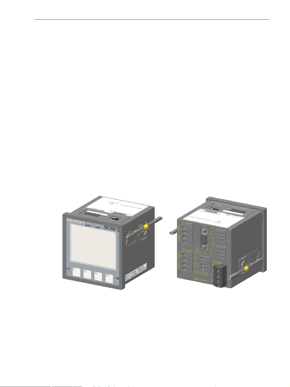
Variants
SICAM Q100
, Display Side
SICAM Q100
with RS485 Interface, Terminal Side
2 Overview
2.1 Device Versions
• Internal Ethernet switch
• Certificates
CE certification
UL certification
• Evaluations
Output of power quality reports
SICAM Q100 is available in different variants:
• Communication via Ethernet
Only Modbus TCP protocol
Modbus TCP protocol or IEC 61850 server protocol
• Serial communication
Without RS485 interface
With RS485 interface:
- Modbus RTUslave protocol
- Modbus RTU master protocol and gateway function
• Degree of protection of front
IP40
SICAM Q100
Figure 2-1 SICAM Q100
E50417-H1040-C522-A6, Edition 06.2019
21SICAM Q100, 7KG95xx, Device Manual
2 Overview
Measurings, Monitoring, Recording and
Power Quality (PQ) Functions
Measurements acc. to standard IEC 61000-4-30, class A
Measured quantities: V, I, f, P, Q, S, W, cos phi, Flicker
Measurement min/max/mean values
Measur em en t s t ill 63th harmonics (curren t, v olt age)
Limit violations
Energy management: Load profiles and tariffs
Transient det ec t ion
Recorder for Power Quality measured values
Event recording, visualisation
Online PQ reporting e.g. acc. to EN 50160
Description
Power Monitoring Device and Power Quality Recorder, Class A
Order No. / MLFB
Device type
Dimensions 96 mm x 96 mm x 100 mm
Panel mounted instrument with graphical display
4 Inputs for AC voltage measurements
4 Inputs for AC current measurements
2 Binary inputs
2 Binary outputs
Web server for parameterization , visualization and data management
Ethernet switch
Internal memory 2 GB
1 2 3 4 5 6 7 8 9 10 11 12 13 14 15 16
1AAA
-
5-97KG
Degree of Protection of Front
IP40
SICAM Q100
CE C ertificat ion and U L Certification
Serial Interface and Communication Protocol
Without
RS485 – Modbus RTU slave, and
Modbus RTU master and gateway function
Ethernet Interface and Communication Protocol, RJ45
Modbus TCP
IEC 61850 server and Modbus TCP
A0
0
3
1
0
2
01
2.2 Ordering Information, Scope of Delivery and Accessories
2.2 Ordering Information, Scope of Delivery and Accessories
Ordering Information
Use the following ordering code to order SICAM Q100 devices:
Figure 2-2 Ordering Code for SICAM Q100
22 SICAM Q100, 7KG95xx, Device Manual
E50417-H1040-C522-A6, Edition 06.2019

Scope of Delivery
The delivery comprises the following components depending on the ordering code:
• SICAM Q100 according to ordering code (see Figure 2-2)
• Battery (insulated in the battery compartment of the device)
• Mounting element
• Product Information
Accessories
You can order the following accessories:
• Device Manual E50417-H1040-C522 (download available at https://www.siemens.com/powerquality)
• RS485 bus terminating plug 220 W in a 9-pin D-sub connector plug: 7XV5103-5AA00
• Connectors for alternating voltage inputs
2 Overview
2.2 Ordering Information, Scope of Delivery and Accessories
Order via:
Phoenix Contact GmbH & Co. KG
Item number: 1700734
Product name: GMSTB 2.5 HCV/ 4-ST-7.62 BK TS
Minimum order quantity: 50 pieces
• Various cables as listed in the following tables:
Table 2-1 RS485-Y Bus Cable (2-Wire, Shielded, with 9-Pin D-sub Connector Plugs)
Cable Length Order No.
1 m 7XV5103-0AA01
3 m 7XV5103-0AA03
5 m 7XV5103-0AA05
10 m 7XV5103-0AA10
Table 2-2 RS485 Bus Extension Cable (2-Wire, Shielded, with 9-Pin D-sub Connector Plugs)
Cable Length Order No.
10 m 7XV5103-1AA10
20 m 7XV5103-1AA20
30 m 7XV5103-1AA30
40 m 7XV5103-1AA40
50 m 7XV5103-1AA50
E50417-H1040-C522-A6, Edition 06.2019
23SICAM Q100, 7KG95xx, Device Manual

2 Overview
2.2 Ordering Information, Scope of Delivery and Accessories
Table 2-3 Ethernet Patch Cable (Double Shielded (SFPT), LAN Connector Plugs on Both Sides)
Cable Length Order No.
0.5 m 7KE6000-8G-D00-0AA5
1.0 m 7KE6000-8G-D00-1AA0
2.0 m 7KE6000-8G-D00-2AA0
3.0 m 7KE6000-8G-D00-3AA0
5.0 m 7KE6000-8G-D00-5AA0
10.0 m 7KE6000-8G-D01-0AA0
15.0 m 7KE6000-8G-D01-5AA0
20.0 m 7KE6000-8G-D02-0AA0
24 SICAM Q100, 7KG95xx, Device Manual
E50417-H1040-C522-A6, Edition 06.2019

3 Device Design
3.1 Mechanical Design 26
3.2 Display and Softkeys 27
3.3 Terminal Diagram of the Back Plate 28
3 Device Design
E50417-H1040-C522-A6, Edition 06.2019
25SICAM Q100, 7KG95xx, Device Manual
3 Device Design
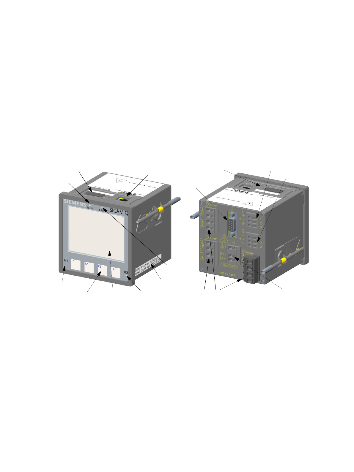
RJ45 with
4LEDs
2LEDs
Cover of battery
compartment
Terminal block for
Default IP address
Default subnet mask
LED RUN
LED ERROR
LED H1
LED H2
Softkeys
F1 to F4
Terminal blocks for
measurements (voltage, current)
power supply
Binary inputs
Display
Terminal side
Display side
D sub
(RS485)
Binary outputs
3.1 Mechanical Design
3.1 Mechanical Design
The device is designed for panel flush mounting. The electrical modules are installed in a plastic case with the
dimensions 96 mm x 96 mm x 100 mm (W x H x D).
The display side of the device contains the display, 4 softkeys located below and 4 LEDs of which the H1, H2,
and ERROR LEDs can be parameterized. The ERROR LED can only be parameterized for error messages.
The device top side holds the RJ45 Ethernet plug connector with 2 LEDs. 4 more LEDs are identical to the
LEDs on the display side. At the cover of the battery compartment, there is a labeling strip for the configurable
LEDs H1/H2 and a battery symbol that indicates the polarity. The label is also on the top side and provides
among other information the most important rated data of the device. A lithium battery is located under the
removable cover of the battery compartment.
SICAM Q100 devices can also contain a D-sub connector plug as RS485 interface (see Figure 3-1) as shown
in the ordering information (see chapter 2.2).
26 SICAM Q100, 7KG95xx, Device Manual
Figure 3-1 Layout of SICAM Q100
E50417-H1040-C522-A6, Edition 06.2019
3.2 Display and Softkeys
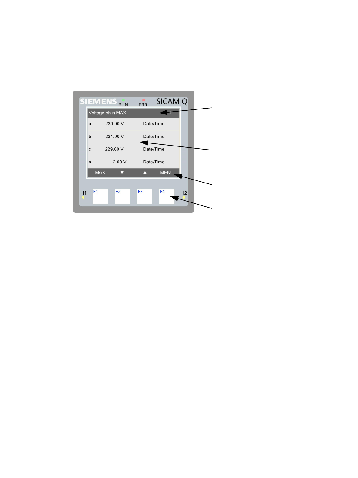
Title
Display area
Softkey functions
Softkeys F1 to F4
Display
The layout of the display is shown in the following figure.
3 Device Design
3.2 Display and Softkeys
Softkeys
Figure 3-2 Display and Softkeys
The top line (title) shows the name of the current display in the display area.
The display area below shows parameter settings, measured values, and graphic pictures.
The bottom line shows the 4 current functions of the softkeys below the display used to set the parameters.
The 4 softkeys on the display side are used to make the desired entries at the device.
To call and activate the IP address, press softkey F4 (for > 3 s, see Figure 3-2) on the right during system
startup if necessary. The IP address and the standard subnet mask are imprinted on the side panel of the device
(see Figure 3-1).
The chapter 10 gives a detailed description of the softkey functions.
E50417-H1040-C522-A6, Edition 06.2019
27SICAM Q100, 7KG95xx, Device Manual
3 Device Design
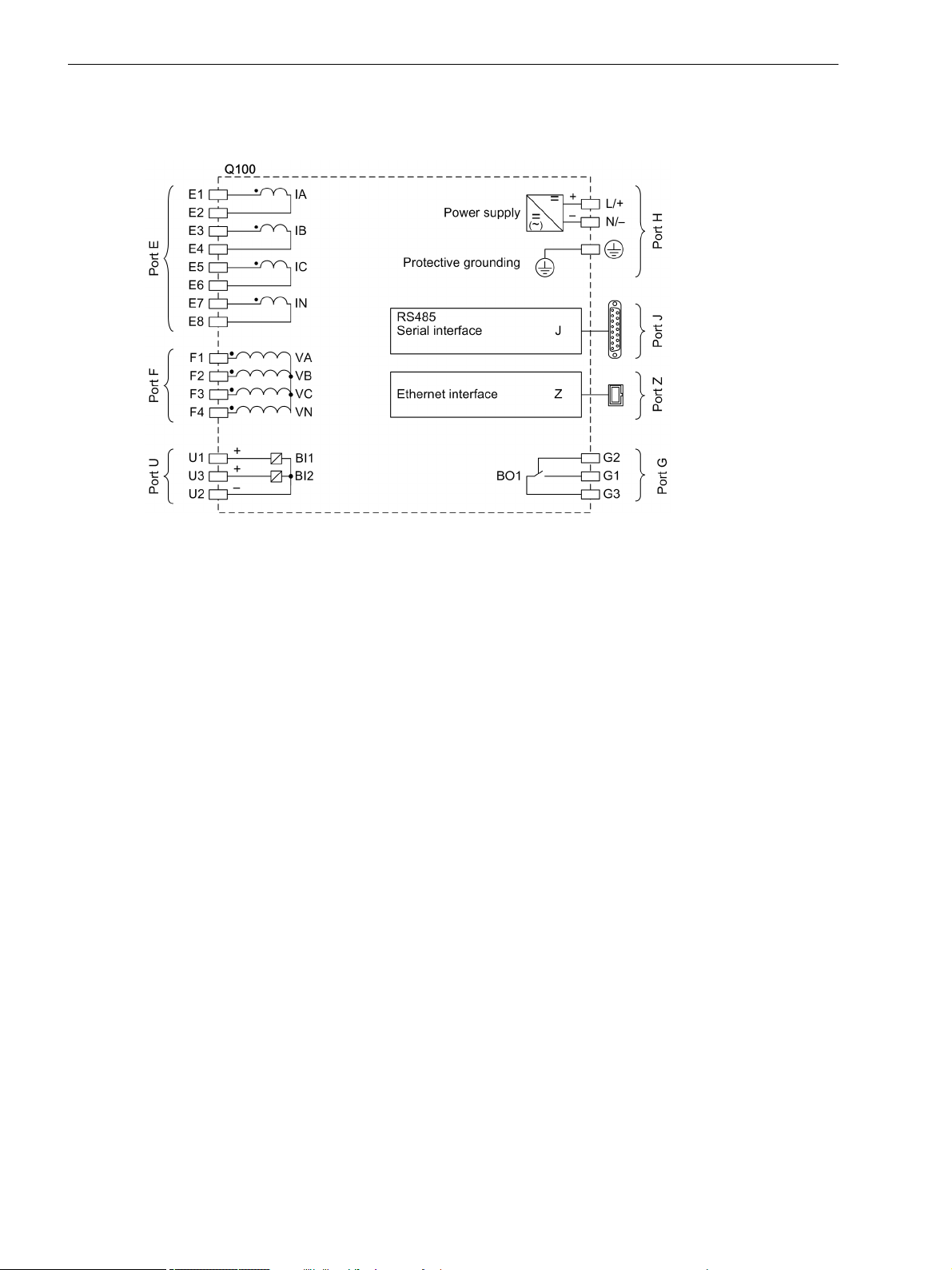
3.3 Terminal Diagram of the Back Plate
3.3 Terminal Diagram of the Back Plate
Figure 3-3 Terminal Diagram of the Back Plate
28 SICAM Q100, 7KG95xx, Device Manual
E50417-H1040-C522-A6, Edition 06.2019

4 Measured Quantities and Recording
4.1 Power Quality Measuring System and Recording System
4.2 Measured Quantities
4.3 Display of Measured Quantities
4 Measured Quantities and Recording
E50417-H1040-C522-A6, Edition 06.2019
29SICAM Q100, 7KG95xx, Device Manual

4 Measured Quantities and Recording
4.1 Power Quality Measuring System and Recording System
4.1 Power Quality Measuring System and Recording System
4.1.1 Measuring System
SICAM Q100 devices measure the power quality according to IEC 61000-4-30 in 1-phase or multi-phase
distribution systems.
The basic measuring interval for determining the values for mains voltage, harmonics of mains voltage, and
mains voltage unbalance is 10 cycles for 50-Hz distribution systems or 12 cycles for 60-Hz distribution systems.
An overview of the measured quantities demanded in according to IEC 61000-4-30, their measurement
uncertainty and measurement ranges is represented in the chapter 4.3.1.
4.1.2 Flicker
The flicker measurement is performed according to IEC 61000-4-15.
The short-term flicker value Pst and long-term flicker value Plt are determined for phase-to-ground voltages
and delta voltages. The flicker measurement is performed on all 3 voltage channels.
Flickers appear with a frequency from 0.005 to 35 Hz. The instantaneous flicker value is displayed in
perceptibility units P.
SICAM Q100 measures the following flicker types:
• Short-term flicker value Pst, determined over 10 min (short-term flicker), fixed
• Long-term flicker value Plt, over 2 h (12 Pst values), fixed
• Perceptibility Pinst
30 SICAM Q100, 7KG95xx, Device Manual
E50417-H1040-C522-A6, Edition 06.2019
 Loading...