

Siemens SICAM MMU 7KG9663 Device Manual

Preface
Open Source Software
Contents
SICAM MMU
7KG9663
Device Manual
User Information 1
Overview 2
Device Design 3
Measurands and Characteristics 4
Getting Started 5
Connection Principle and Applications 6
Operation 7
Time Synchronization 8
Communication 9
Calibration 10
Maintenance, Storage, Transport 11
E50417-H1040-C514-A3
Failures and LED Indications 12
Technical Data 13
Operational Indications 14
Operating Parameters 15
Glossary
Index

NOTE
For your own safety, please observe the warnings and safety instructions contained in this document.
Disclaimer of Liability
This document has been subjected to rigorous technical review
before being published. It is revised at regular intervals, and any
modifications and amendments are included in the subsequent
issues. The content of this document has been compiled for
information purposes only. Although Siemens AG has made best
efforts to keep the document as precise and up-to-date as possible,
Siemens AG shall not assume any liability for defects and damage
which result through use of the information contained herein.
This content does not form part of a contract or of business
relations; nor does it change these. All obligations of Siemens AG
are stated in the relevant contractual agreements.
Siemens AG reserves the right to revise this document from time to
time.
Document release E50417-H1040-C514-A3.00
Edition 01.2016
Product version: V2.0
Copyright
Copyright © Siemens AG 2016. All rights reserved.
The disclosure, duplication, distribution and editing of this
document, or utilization and communication of the content are not
permitted, unless authorized in writing. All rights, including rights
created by patent grant or registration of a utility model or a design,
are reserved.
Registered Trademarks
®
SIPROTEC
SIEMENS AG. An unauthorized use is illegal.
All other designations in this document can be trademarks whose
use by third parties for their own purposes can infringe the rights of
the owner.
and SICAM® are registered trademarks of

Preface
Purpose of this Manual
This manual describes the application, functions, installation, commissioning and operation of the
SICAM MMU 7KG9663.
Target Group
This manual is intended for project engineers, commissioning and operating personnel in electrical systems
and power plants.
Scope of Vali dity of this Manual
This manual is valid for the SICAM MMU 7KG9663.
Further Support
For any questions concerning your system, please contact your Siemens representative.
The Siemens Customer Support Center provides around-the-clock support.
Phone: +49 (1805) 24-8437
Fax: +49 (1805) 24-2471
Internet: http://www.powerquality.de
e-mail: support.ic@siemens.com
Training Courses
If you are interested in our current training program, please contact our training center:
Siemens AG
Siemens Power Academy TD
Humboldtstr. 59
D-90459 Nuremberg
Tel.: +49 (911) 433-7415
Fax: +49 (911) 433-5482
e-mail: poweracademy.ic-sg@siemens.com
Internet: http://www.siemens.com/poweracademy
E50417-H1040-C514-A3, Edition 01.2016
3SICAM MMU 7KG9663, Device Manual
Notes On Safety
This manual does not constitute a complete catalog of all safety measures required for operating the equipment
(module, device) in question, because special operating conditions may require additional measures. However,
it does contain notes that must be adhered to for your own personal safety and to avoid damage to property.
These notes are highlighted with a warning triangle and different keywords indicating different degrees of danger.
DANGER
Danger means that death or severe injury will occur if the appropriate safety measures are not taken.
✧ Follow all advice instructions to prevent death or severe injury.
WARNING
Warning means that death or severe injury can occur if the appropriate safety measures are not taken.
✧ Follow all advice instructions to prevent death or severe injury.
CAUTION
Caution means that minor or moderate injury can occur if the appropriate safety measures are not taken.
✧ Follow all advice instructions to prevent minor injury.
NOTICE
Notice means that damage to property can occur if the appropriate safety measures are not taken.
✧ Follow all advice instructions to prevent damage to property.
NOTE
is important information about the product, the handling of the product, or the part of the documentation in
question to which special attention must be paid.
4 SICAM MMU 7KG9663, Device Manual
E50417-H1040-C514-A3, Edition 01.2016

Personnel Qualified in Electrical Engineering
Only qualified electrical engineering personnel may commission and operate the equipment (module, device)
described in this document. Qualified electrical engineering personnel in the sense of this manual are people
who can demonstrate technical qualifications as electrical technicians. These persons may commission, isolate, ground, and label devices, systems and circuits according to the standards of safety engineering.
Use as Prescribed
The equipment (device, module) must not be used for any other purposes than those described in the Catalog
and the Technical Description. If it is used together with third-party devices and components, these must be
recommended or approved by Siemens.
If the device is not used in accordance with the Product Information and this manual, the scheduled protection
is impaired.
Problem-free and safe operation of the product depends on the following:
• Proper transport
• Proper storage, setup, and installation
• Proper operation and maintenance
When electrical equipment is operated, hazardous voltages are inevitably present in certain parts. If proper action is not taken, death, severe injury, or property damage can result.
• The equipment must be grounded at the grounding terminal before any connections are made.
• All circuit components connected to the power supply may be subject to dangerous voltage.
• Hazardous voltages may be present in equipment even after the supply voltage has been disconnected
(capacitors can still be charged).
• Equipment with exposed current transformer circuits must not be operated. Prior to disconnecting the
equipment, ensure that the current transformer circuits are short-circuited.
• The limit values stated in the document may not be exceeded. This must also be considered during testing
and commissioning.
E50417-H1040-C514-A3, Edition 01.2016
5SICAM MMU 7KG9663, Device Manual
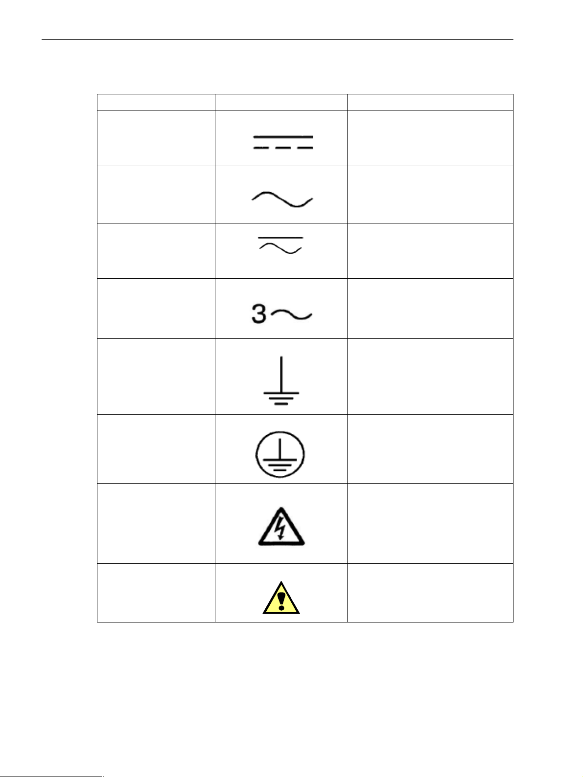
Used Symbols
No. Symbol Description
1 Direct current
IEC 60417-5031
2 Alternating current
IEC 60417-5032
3 Direct current and alternating current
IEC 60417-5033
4 Three-phase alternating current
5 Earth (ground) terminal
IEC 60417-5017
6 Protective conductor terminal
IEC 60417-5019
7 Caution, risk of electric shock
8 Caution, risk of danger
ISO 7000-0434
6 SICAM MMU 7KG9663, Device Manual
E50417-H1040-C514-A3, Edition 01.2016
Statement of Conformity
This product complies with the directive of the Council of the European Communities on the approximation of the laws of the Member States relating to electromagnetic compatibility (EMC Council Directive 2004/108/EC - valid until April, 19th of 2016, EMC Council Directive 2014/30/EU - valid from
April, 20th of 2016) and concerning electrical equipment for use within specified voltage limits (Lowvoltage Directive 2006/95/EC - valid until April, 19th of 2016, Low Voltage Directive 2014/35/EU valid from April, 20th of 2016).
This conformity has been established by means of tests conducted by Siemens AG according to the
Council Directive in agreement with the generic standards
EN 61000-6-2 and EN 61000-6-4 for the EMC directives, and with the standard EN 61010-1 for the
low-voltage directive.
The device has been designed and produced for industrial use.
The product conforms to the standard EN 60688.
Further Standards
This product is UL-certified to Standard UL 61010-1, third edition, based on the specification stated in chapter 13.1
(Technical Data). UL File No.: E228586.
Open-type Measuring Equipment
2UD1
E50417-H1040-C514-A3, Edition 01.2016
7SICAM MMU 7KG9663, Device Manual

8 SICAM MMU 7KG9663, Device Manual
E50417-H1040-C514-A3, Edition 01.2016

Open Source Software
The product contains, among other things, Open Source Software developed by third parties. The Open Source
Software used in the product and the license agreements concerning this software can be found in the
Readme_OSS.
These Open Source Software files are protected by copyright. Your compliance with those license conditions
will entitle you to use the Open Source Software as foreseen in the relevant license. In the event of conflicts
between Siemens license conditions and the Open Source Software license conditions, the Open Source Software conditions shall prevail with respect to the Open Source Software portions of the software.
The Open Source Software is licensed royalty-free. Insofar as the applicable Open Source Software License
Conditions provide for it you can order the source code of the Open Source Software from your Siemens sales
contact - against payment of the shipping and handling charges - for a period of at least 3 years since purchase
of the Product. We are liable for the Product including the Open Source Software contained in it pursuant to
the license conditions applicable to the Product. Any liability for the Open Source Software beyond the program
flow intended for the Product is explicitly excluded. Furthermore any liability for defects resulting from modifications to the Open Source Software by you or third parties is excluded. We do not provide any technical support for the Product if it has been modified.
E50417-H1040-C514-A3, Edition 01.2016
9SICAM MMU 7KG9663, Device Manual

Glossary
10 SICAM MMU 7KG9663, Device Manual
E50417-H1040-C514-A3, Edition 01.2016

Contents
Preface . . . . . . . . . . . . . . . . . . . . . . . . . . . . . . . . . . . . . . . . . . . . . . . . . . . . . . . . . . . . . . . . . . . . . . . . . . . . . . . . . . 3
Open Source Software . . . . . . . . . . . . . . . . . . . . . . . . . . . . . . . . . . . . . . . . . . . . . . . . . . . . . . . . . . . . . . . . . . . . . 9
1 User Information . . . . . . . . . . . . . . . . . . . . . . . . . . . . . . . . . . . . . . . . . . . . . . . . . . . . . . . . . . . . . . . . . . . . . . . . . 15
2 Overview. . . . . . . . . . . . . . . . . . . . . . . . . . . . . . . . . . . . . . . . . . . . . . . . . . . . . . . . . . . . . . . . . . . . . . . . . . . . . . . . 17
2.1 Versions of SICAM MMU . . . . . . . . . . . . . . . . . . . . . . . . . . . . . . . . . . . . . . . . . . . . . . . . . . . . . . . . . . . 18
2.2 Ordering Information, Scope of Delivery and Accessories . . . . . . . . . . . . . . . . . . . . . . . . . . . . . . . . . . 19
2.2.1 Ordering Information for SICAM MMU . . . . . . . . . . . . . . . . . . . . . . . . . . . . . . . . . . . . . . . . . . . . . . 19
2.2.2 Ordering Information for Subdevice SICAM I/O Unit 7XV5673. . . . . . . . . . . . . . . . . . . . . . . . . . . . 21
3 Device Design . . . . . . . . . . . . . . . . . . . . . . . . . . . . . . . . . . . . . . . . . . . . . . . . . . . . . . . . . . . . . . . . . . . . . . . . . . . 23
3.1 Mechanical Design . . . . . . . . . . . . . . . . . . . . . . . . . . . . . . . . . . . . . . . . . . . . . . . . . . . . . . . . . . . . . . . . 24
3.2 Electrical Design. . . . . . . . . . . . . . . . . . . . . . . . . . . . . . . . . . . . . . . . . . . . . . . . . . . . . . . . . . . . . . . . . . 25
4 Measurands and Characteristics . . . . . . . . . . . . . . . . . . . . . . . . . . . . . . . . . . . . . . . . . . . . . . . . . . . . . . . . . . . . 27
4.1 Measurands . . . . . . . . . . . . . . . . . . . . . . . . . . . . . . . . . . . . . . . . . . . . . . . . . . . . . . . . . . . . . . . . . . . . . 28
4.1.1 Measurands in 1-phase Systems . . . . . . . . . . . . . . . . . . . . . . . . . . . . . . . . . . . . . . . . . . . . . . . . . . 28
4.1.2 Measurands in 3-wire and 4-wire Networks . . . . . . . . . . . . . . . . . . . . . . . . . . . . . . . . . . . . . . . . . . 29
4.1.3 Measurands Depending on the Connection Type. . . . . . . . . . . . . . . . . . . . . . . . . . . . . . . . . . . . . . 30
4.2 Display of Measurands. . . . . . . . . . . . . . . . . . . . . . . . . . . . . . . . . . . . . . . . . . . . . . . . . . . . . . . . . . . . . 35
4.3 Calculation of the Measurands . . . . . . . . . . . . . . . . . . . . . . . . . . . . . . . . . . . . . . . . . . . . . . . . . . . . . . 37
5 Getting Started. . . . . . . . . . . . . . . . . . . . . . . . . . . . . . . . . . . . . . . . . . . . . . . . . . . . . . . . . . . . . . . . . . . . . . . . . . . 41
5.1 Unpacking, Inspecting the Delivery and Installing the Battery . . . . . . . . . . . . . . . . . . . . . . . . . . . . . . . 42
5.2 Assembly . . . . . . . . . . . . . . . . . . . . . . . . . . . . . . . . . . . . . . . . . . . . . . . . . . . . . . . . . . . . . . . . . . . . . . . 44
5.2.1 General Assembly Notes . . . . . . . . . . . . . . . . . . . . . . . . . . . . . . . . . . . . . . . . . . . . . . . . . . . . . . . . 44
5.2.2 Assembly. . . . . . . . . . . . . . . . . . . . . . . . . . . . . . . . . . . . . . . . . . . . . . . . . . . . . . . . . . . . . . . . . . . . . 45
5.3 Electrical Connection . . . . . . . . . . . . . . . . . . . . . . . . . . . . . . . . . . . . . . . . . . . . . . . . . . . . . . . . . . . . . . 46
5.3.1 Safety Notes . . . . . . . . . . . . . . . . . . . . . . . . . . . . . . . . . . . . . . . . . . . . . . . . . . . . . . . . . . . . . . . . . . 46
5.3.2 Electrical Connection of SICAM MMU . . . . . . . . . . . . . . . . . . . . . . . . . . . . . . . . . . . . . . . . . . . . . . 47
5.4 System Requirements . . . . . . . . . . . . . . . . . . . . . . . . . . . . . . . . . . . . . . . . . . . . . . . . . . . . . . . . . . . . . 48
5.5 Access Rights. . . . . . . . . . . . . . . . . . . . . . . . . . . . . . . . . . . . . . . . . . . . . . . . . . . . . . . . . . . . . . . . . . . . 49
5.6 Meaning of the LEDs . . . . . . . . . . . . . . . . . . . . . . . . . . . . . . . . . . . . . . . . . . . . . . . . . . . . . . . . . . . . . . 50
5.7 Commissioning. . . . . . . . . . . . . . . . . . . . . . . . . . . . . . . . . . . . . . . . . . . . . . . . . . . . . . . . . . . . . . . . . . . 51
5.7.1 Initial Commissioning . . . . . . . . . . . . . . . . . . . . . . . . . . . . . . . . . . . . . . . . . . . . . . . . . . . . . . . . . . . 51
5.7.2 Changes During Operation. . . . . . . . . . . . . . . . . . . . . . . . . . . . . . . . . . . . . . . . . . . . . . . . . . . . . . . 52
5.7.3 Starting the Device with the Default IP Address. . . . . . . . . . . . . . . . . . . . . . . . . . . . . . . . . . . . . . . 53
E50417-H1040-C514-A3, Edition 01.2016
11SICAM MMU 7KG9663, Device Manual

6 Connection Principle and Applications . . . . . . . . . . . . . . . . . . . . . . . . . . . . . . . . . . . . . . . . . . . . . . . . . . . . . . 55
6.1 Terminals . . . . . . . . . . . . . . . . . . . . . . . . . . . . . . . . . . . . . . . . . . . . . . . . . . . . . . . . . . . . . . . . . . . . . . . 56
6.2 Communication Interface. . . . . . . . . . . . . . . . . . . . . . . . . . . . . . . . . . . . . . . . . . . . . . . . . . . . . . . . . . . 58
6.2.1 Ethernet Interface. . . . . . . . . . . . . . . . . . . . . . . . . . . . . . . . . . . . . . . . . . . . . . . . . . . . . . . . . . . . . . 58
6.3 Connection Types and Connection Examples. . . . . . . . . . . . . . . . . . . . . . . . . . . . . . . . . . . . . . . . . . . 59
6.3.1 Using SICAM MMU in the Power Systems IT, TT and TN. . . . . . . . . . . . . . . . . . . . . . . . . . . . . . . 59
6.3.2 Connection Types . . . . . . . . . . . . . . . . . . . . . . . . . . . . . . . . . . . . . . . . . . . . . . . . . . . . . . . . . . . . . 59
6.3.3 Connection Examples - Standard Application . . . . . . . . . . . . . . . . . . . . . . . . . . . . . . . . . . . . . . . . 60
6.3.4 Connection Example - Special Application. . . . . . . . . . . . . . . . . . . . . . . . . . . . . . . . . . . . . . . . . . . 70
6.4 Application Examples SICAM MMU with SICAM I/O Unit 7XV5673 . . . . . . . . . . . . . . . . . . . . . . . . . . 71
6.4.1 Direct Connection of a SICAM MMU to a SICAM I/O Unit 7XV5673 and Connection to the Control
Center. . . . . . . . . . . . . . . . . . . . . . . . . . . . . . . . . . . . . . . . . . . . . . . . . . . . . . . . . . . . . . . . . . . . . . . 71
6.4.2 Connecting Multiple Device Combinations to the Control Center . . . . . . . . . . . . . . . . . . . . . . . . . 72
6.4.3 Creating a Device Combination via an External Ethernet Switch and Connection to the Control Center
73
6.4.4 Connecting Multiple Device Combinations to the Control Center via External Ethernet Switches. 74
7 Operation. . . . . . . . . . . . . . . . . . . . . . . . . . . . . . . . . . . . . . . . . . . . . . . . . . . . . . . . . . . . . . . . . . . . . . . . . . . . . . . 75
7.1 General Usage Notes. . . . . . . . . . . . . . . . . . . . . . . . . . . . . . . . . . . . . . . . . . . . . . . . . . . . . . . . . . . . . . 76
7.2 Start and Design of the User Interface . . . . . . . . . . . . . . . . . . . . . . . . . . . . . . . . . . . . . . . . . . . . . . . . . 77
7.2.1 Initial Start of the User Interface. . . . . . . . . . . . . . . . . . . . . . . . . . . . . . . . . . . . . . . . . . . . . . . . . . . 77
7.2.2 Enabling JavaScript . . . . . . . . . . . . . . . . . . . . . . . . . . . . . . . . . . . . . . . . . . . . . . . . . . . . . . . . . . . . 78
7.2.3 Number of Connections via HTTP . . . . . . . . . . . . . . . . . . . . . . . . . . . . . . . . . . . . . . . . . . . . . . . . . 79
7.2.4 Layout of the User Interface. . . . . . . . . . . . . . . . . . . . . . . . . . . . . . . . . . . . . . . . . . . . . . . . . . . . . . 80
7.2.5 Starting the User Interface during Operation . . . . . . . . . . . . . . . . . . . . . . . . . . . . . . . . . . . . . . . . . 81
7.3 Configuration of the Device . . . . . . . . . . . . . . . . . . . . . . . . . . . . . . . . . . . . . . . . . . . . . . . . . . . . . . . . . 86
7.3.1 Device Configuration Procedure . . . . . . . . . . . . . . . . . . . . . . . . . . . . . . . . . . . . . . . . . . . . . . . . . . 86
7.3.2 Access to the Passive Set of Parameters by Multiple Users . . . . . . . . . . . . . . . . . . . . . . . . . . . . . 93
7.3.3 Setting the Operational Parameters. . . . . . . . . . . . . . . . . . . . . . . . . . . . . . . . . . . . . . . . . . . . . . . . 94
7.3.4 Setting Administrative Parameters. . . . . . . . . . . . . . . . . . . . . . . . . . . . . . . . . . . . . . . . . . . . . . . . 108
7.3.5 Finish Configuration . . . . . . . . . . . . . . . . . . . . . . . . . . . . . . . . . . . . . . . . . . . . . . . . . . . . . . . . . . . 128
7.4 Value View. . . . . . . . . . . . . . . . . . . . . . . . . . . . . . . . . . . . . . . . . . . . . . . . . . . . . . . . . . . . . . . . . . . . . 129
7.5 Maintenance. . . . . . . . . . . . . . . . . . . . . . . . . . . . . . . . . . . . . . . . . . . . . . . . . . . . . . . . . . . . . . . . . . . . 130
7.5.1 Firmware Upload . . . . . . . . . . . . . . . . . . . . . . . . . . . . . . . . . . . . . . . . . . . . . . . . . . . . . . . . . . . . . 131
7.5.2 Calibration . . . . . . . . . . . . . . . . . . . . . . . . . . . . . . . . . . . . . . . . . . . . . . . . . . . . . . . . . . . . . . . . . . 132
7.5.3 Presettings . . . . . . . . . . . . . . . . . . . . . . . . . . . . . . . . . . . . . . . . . . . . . . . . . . . . . . . . . . . . . . . . . . 133
7.5.4 Message Logs . . . . . . . . . . . . . . . . . . . . . . . . . . . . . . . . . . . . . . . . . . . . . . . . . . . . . . . . . . . . . . . 135
7.5.5 Diagnosis . . . . . . . . . . . . . . . . . . . . . . . . . . . . . . . . . . . . . . . . . . . . . . . . . . . . . . . . . . . . . . . . . . . 137
8 Time Synchronization. . . . . . . . . . . . . . . . . . . . . . . . . . . . . . . . . . . . . . . . . . . . . . . . . . . . . . . . . . . . . . . . . . . . 141
8.1 General . . . . . . . . . . . . . . . . . . . . . . . . . . . . . . . . . . . . . . . . . . . . . . . . . . . . . . . . . . . . . . . . . . . . . . . 142
8.2 Internal Time Keeping . . . . . . . . . . . . . . . . . . . . . . . . . . . . . . . . . . . . . . . . . . . . . . . . . . . . . . . . . . . . 142
8.2.1 Time Format. . . . . . . . . . . . . . . . . . . . . . . . . . . . . . . . . . . . . . . . . . . . . . . . . . . . . . . . . . . . . . . . . 142
8.2.2 Status Bits . . . . . . . . . . . . . . . . . . . . . . . . . . . . . . . . . . . . . . . . . . . . . . . . . . . . . . . . . . . . . . . . . . 142
8.3 External Time Synchronization via Ethernet NTP . . . . . . . . . . . . . . . . . . . . . . . . . . . . . . . . . . . . . . . 143
8.4 Internal Time Synchronization via RTC . . . . . . . . . . . . . . . . . . . . . . . . . . . . . . . . . . . . . . . . . . . . . . . 144
12 SICAM MMU 7KG9663, Device Manual
E50417-H1040-C514-A3, Edition 01.2016

9 Communication . . . . . . . . . . . . . . . . . . . . . . . . . . . . . . . . . . . . . . . . . . . . . . . . . . . . . . . . . . . . . . . . . . . . . . . . . 145
9.1 Communication Feature . . . . . . . . . . . . . . . . . . . . . . . . . . . . . . . . . . . . . . . . . . . . . . . . . . . . . . . . . . . 146
9.1.1 Ethernet Communication. . . . . . . . . . . . . . . . . . . . . . . . . . . . . . . . . . . . . . . . . . . . . . . . . . . . . . . . 146
9.2 Modbus. . . . . . . . . . . . . . . . . . . . . . . . . . . . . . . . . . . . . . . . . . . . . . . . . . . . . . . . . . . . . . . . . . . . . . . . 149
9.2.1 Modbus Functions. . . . . . . . . . . . . . . . . . . . . . . . . . . . . . . . . . . . . . . . . . . . . . . . . . . . . . . . . . . . . 149
9.2.2 Exception Responses . . . . . . . . . . . . . . . . . . . . . . . . . . . . . . . . . . . . . . . . . . . . . . . . . . . . . . . . . . 149
9.2.3 Modbus TCP. . . . . . . . . . . . . . . . . . . . . . . . . . . . . . . . . . . . . . . . . . . . . . . . . . . . . . . . . . . . . . . . . 150
9.2.4 Communication with the Subdevic e SIC A M I/O Un it 7XV5673. . . . . . . . . . . . . . . . . . . . . . . . . . . 152
9.2.5 Register Assignment. . . . . . . . . . . . . . . . . . . . . . . . . . . . . . . . . . . . . . . . . . . . . . . . . . . . . . . . . . . 154
9.2.6 Data Types . . . . . . . . . . . . . . . . . . . . . . . . . . . . . . . . . . . . . . . . . . . . . . . . . . . . . . . . . . . . . . . . . . 154
9.2.7 Data in the Modbus Registers (Data Mapping). . . . . . . . . . . . . . . . . . . . . . . . . . . . . . . . . . . . . . . 159
9.2.8 Modbus TCP Diagnosis . . . . . . . . . . . . . . . . . . . . . . . . . . . . . . . . . . . . . . . . . . . . . . . . . . . . . . . . 188
9.3 IEC 60870-5-104 . . . . . . . . . . . . . . . . . . . . . . . . . . . . . . . . . . . . . . . . . . . . . . . . . . . . . . . . . . . . . . . . 190
9.3.1 Function Range. . . . . . . . . . . . . . . . . . . . . . . . . . . . . . . . . . . . . . . . . . . . . . . . . . . . . . . . . . . . . . . 190
9.3.2 Parameterization. . . . . . . . . . . . . . . . . . . . . . . . . . . . . . . . . . . . . . . . . . . . . . . . . . . . . . . . . . . . . . 190
9.3.3 Redundancy . . . . . . . . . . . . . . . . . . . . . . . . . . . . . . . . . . . . . . . . . . . . . . . . . . . . . . . . . . . . . . . . . 190
9.3.4 Communication with the SICAM I/O Unit 7XV5673 Subdevice. . . . . . . . . . . . . . . . . . . . . . . . . . . 192
9.3.5 Information Objects. . . . . . . . . . . . . . . . . . . . . . . . . . . . . . . . . . . . . . . . . . . . . . . . . . . . . . . . . . . . 195
9.3.6 Energy Values/Energy Counters. . . . . . . . . . . . . . . . . . . . . . . . . . . . . . . . . . . . . . . . . . . . . . . . . . 195
9.3.7 IEC 60870-5-104 Diagnosis . . . . . . . . . . . . . . . . . . . . . . . . . . . . . . . . . . . . . . . . . . . . . . . . . . . . . 197
10 Calibration . . . . . . . . . . . . . . . . . . . . . . . . . . . . . . . . . . . . . . . . . . . . . . . . . . . . . . . . . . . . . . . . . . . . . . . . . . . . . 199
10.1 General. . . . . . . . . . . . . . . . . . . . . . . . . . . . . . . . . . . . . . . . . . . . . . . . . . . . . . . . . . . . . . . . . . . . . . . . 200
10.2 Calibrating the Alternating-Voltage Measuring Range . . . . . . . . . . . . . . . . . . . . . . . . . . . . . . . . . . . . 201
10.3 Calibrating the Alternating Current Measuring Range . . . . . . . . . . . . . . . . . . . . . . . . . . . . . . . . . . . . 204
10.4 Calibrating the Measuring Voltage Input of Neutral Conductor VN . . . . . . . . . . . . . . . . . . . . . . . . . . 207
10.4.1 Calibrating SICAM MMU (Potential Divider Voltage Measurement) . . . . . . . . . . . . . . . . . . . . . . . 207
10.4.2 Calibrating SICAM MMU (Galvanic Isolated Voltage Measurement) . . . . . . . . . . . . . . . . . . . . . . 210
10.5 Calibrating the Phase Angle. . . . . . . . . . . . . . . . . . . . . . . . . . . . . . . . . . . . . . . . . . . . . . . . . . . . . . . . 211
11 Maintenance, Storage, Transport. . . . . . . . . . . . . . . . . . . . . . . . . . . . . . . . . . . . . . . . . . . . . . . . . . . . . . . . . . . 215
11.1 Maintenance. . . . . . . . . . . . . . . . . . . . . . . . . . . . . . . . . . . . . . . . . . . . . . . . . . . . . . . . . . . . . . . . . . . . 216
11.2 Storage. . . . . . . . . . . . . . . . . . . . . . . . . . . . . . . . . . . . . . . . . . . . . . . . . . . . . . . . . . . . . . . . . . . . . . . . 216
11.3 Transport . . . . . . . . . . . . . . . . . . . . . . . . . . . . . . . . . . . . . . . . . . . . . . . . . . . . . . . . . . . . . . . . . . . . . . 216
12 Failures and LED Indications . . . . . . . . . . . . . . . . . . . . . . . . . . . . . . . . . . . . . . . . . . . . . . . . . . . . . . . . . . . . . . 217
12.1 General Inspection . . . . . . . . . . . . . . . . . . . . . . . . . . . . . . . . . . . . . . . . . . . . . . . . . . . . . . . . . . . . . . . 218
12.2 Commissioning during Failures . . . . . . . . . . . . . . . . . . . . . . . . . . . . . . . . . . . . . . . . . . . . . . . . . . . . . 219
12.2.1 Automatic Start of the Boot Loader. . . . . . . . . . . . . . . . . . . . . . . . . . . . . . . . . . . . . . . . . . . . . . . . 219
12.2.2 Manual Start of the Boot Loader. . . . . . . . . . . . . . . . . . . . . . . . . . . . . . . . . . . . . . . . . . . . . . . . . . 220
12.3 Indications Signaled by LEDs. . . . . . . . . . . . . . . . . . . . . . . . . . . . . . . . . . . . . . . . . . . . . . . . . . . . . . . 221
12.4 Troubleshooting and Repair . . . . . . . . . . . . . . . . . . . . . . . . . . . . . . . . . . . . . . . . . . . . . . . . . . . . . . . . 225
E50417-H1040-C514-A3, Edition 01.2016
13SICAM MMU 7KG9663, Device Manual

13 Technical Data. . . . . . . . . . . . . . . . . . . . . . . . . . . . . . . . . . . . . . . . . . . . . . . . . . . . . . . . . . . . . . . . . . . . . . . . . . 227
13.1 General Device Data . . . . . . . . . . . . . . . . . . . . . . . . . . . . . . . . . . . . . . . . . . . . . . . . . . . . . . . . . . . . . 228
13.1.1 Power Supply. . . . . . . . . . . . . . . . . . . . . . . . . . . . . . . . . . . . . . . . . . . . . . . . . . . . . . . . . . . . . . . . 228
13.1.2 Inputs and Outputs. . . . . . . . . . . . . . . . . . . . . . . . . . . . . . . . . . . . . . . . . . . . . . . . . . . . . . . . . . . . 229
13.1.3 Communication Interfaces . . . . . . . . . . . . . . . . . . . . . . . . . . . . . . . . . . . . . . . . . . . . . . . . . . . . . . 231
13.1.4 Environmental Data . . . . . . . . . . . . . . . . . . . . . . . . . . . . . . . . . . . . . . . . . . . . . . . . . . . . . . . . . . . 232
13.1.5 General Data . . . . . . . . . . . . . . . . . . . . . . . . . . . . . . . . . . . . . . . . . . . . . . . . . . . . . . . . . . . . . . . . 232
13.2 Test Data . . . . . . . . . . . . . . . . . . . . . . . . . . . . . . . . . . . . . . . . . . . . . . . . . . . . . . . . . . . . . . . . . . . . . . 233
13.2.1 Electrical Tests. . . . . . . . . . . . . . . . . . . . . . . . . . . . . . . . . . . . . . . . . . . . . . . . . . . . . . . . . . . . . . . 233
13.2.2 Mechanical Stress Tests . . . . . . . . . . . . . . . . . . . . . . . . . . . . . . . . . . . . . . . . . . . . . . . . . . . . . . . 235
13.2.3 Climatic Stress Tests . . . . . . . . . . . . . . . . . . . . . . . . . . . . . . . . . . . . . . . . . . . . . . . . . . . . . . . . . . 236
13.2.4 Safety Standards . . . . . . . . . . . . . . . . . . . . . . . . . . . . . . . . . . . . . . . . . . . . . . . . . . . . . . . . . . . . . 236
13.3 Dimensions . . . . . . . . . . . . . . . . . . . . . . . . . . . . . . . . . . . . . . . . . . . . . . . . . . . . . . . . . . . . . . . . . . . . 237
14 Operational Indications . . . . . . . . . . . . . . . . . . . . . . . . . . . . . . . . . . . . . . . . . . . . . . . . . . . . . . . . . . . . . . . . . . 239
15 Operating Parameters. . . . . . . . . . . . . . . . . . . . . . . . . . . . . . . . . . . . . . . . . . . . . . . . . . . . . . . . . . . . . . . . . . . . 243
15.1 Process Connections. . . . . . . . . . . . . . . . . . . . . . . . . . . . . . . . . . . . . . . . . . . . . . . . . . . . . . . . . . . . . 244
15.1.1 AC Measurement . . . . . . . . . . . . . . . . . . . . . . . . . . . . . . . . . . . . . . . . . . . . . . . . . . . . . . . . . . . . . 244
15.1.2 Binary Outputs . . . . . . . . . . . . . . . . . . . . . . . . . . . . . . . . . . . . . . . . . . . . . . . . . . . . . . . . . . . . . . . 245
15.1.3 LEDs. . . . . . . . . . . . . . . . . . . . . . . . . . . . . . . . . . . . . . . . . . . . . . . . . . . . . . . . . . . . . . . . . . . . . . . 246
15.2 Automation Functions . . . . . . . . . . . . . . . . . . . . . . . . . . . . . . . . . . . . . . . . . . . . . . . . . . . . . . . . . . . . 247
15.3 Administrative. . . . . . . . . . . . . . . . . . . . . . . . . . . . . . . . . . . . . . . . . . . . . . . . . . . . . . . . . . . . . . . . . . . 248
15.3.1 Time Synchronization. . . . . . . . . . . . . . . . . . . . . . . . . . . . . . . . . . . . . . . . . . . . . . . . . . . . . . . . . . 248
15.3.2 Ethernet Communication . . . . . . . . . . . . . . . . . . . . . . . . . . . . . . . . . . . . . . . . . . . . . . . . . . . . . . . 249
15.3.3 SICAM I/O Unit 7XV5673 (Subdevice). . . . . . . . . . . . . . . . . . . . . . . . . . . . . . . . . . . . . . . . . . . . . 254
15.3.4 Device and Language . . . . . . . . . . . . . . . . . . . . . . . . . . . . . . . . . . . . . . . . . . . . . . . . . . . . . . . . . 255
Glossary. . . . . . . . . . . . . . . . . . . . . . . . . . . . . . . . . . . . . . . . . . . . . . . . . . . . . . . . . . . . . . . . . . . . . . . . . . . . . . . 257
Index. . . . . . . . . . . . . . . . . . . . . . . . . . . . . . . . . . . . . . . . . . . . . . . . . . . . . . . . . . . . . . . . . . . . . . . . . . . . . . . . . . 261
14 SICAM MMU 7KG9663, Device Manual
E50417-H1040-C514-A3, Edition 01.2016

1 User Information
Application
The SICAM Measurement and Monitoring Unit (MMU) is capable of measuring electrical quantities (e.g. alternating current, alternating voltage) in power-supply systems. Transmission of quantities to the control center
can take place e.g. directly with IEC 60870-5-104 protocol. The device with protection class IP20 is used in 1phase systems, in 3-wire and 4-wire systems (with neutral conductor). It is mainly applied by power utilities but
also in other industrial and commercial sectors.
The measurements are obtained from the alternating quantities of current and voltage supplied to the AC inputs. Without using external voltage and current transformers, the device can process rated input AC voltages
up to V
currents up to a maximum of 5 A.
Depending on the device type, the input circuits for voltage measurement are either designed as voltage dividers or they are galvanically isolated. Devices with galvanic isolation can be used without voltage transformers
in the power systems IT, TT and TN. Devices with a voltage divider can also be used in these power systems;
for IT power systems, however, an upstream voltage transformer is required.
After conversion via the Ethernet interface, the output values can be transferred as digital data to automation
systems or other systems.
T o add 6 binary inputs and 6 binary outputs to the SICAM MMU, a SICAM I/O Unit 7XV5673 can be connected
to the Ethernet interface. The SICAM I/O Unit 7XV5673 can be connected either directly via the Ethernet switch
of the SICAM I/O Unit or via an external switch.
The integrated web server can be used to set the parameters and display the measured values on HTML pages
from the connected PC or notebook.
= 400 V (347 V for UL conditions) and V
ph-N
= 690 V (600 V for UL conditions) and rated input AC
ph-ph
Measurands
The following measurands can be recorded or calculated from the measured quantities:
• Alternating voltage and alternating current
• Unbalanced of alternating voltage and alternating current
• Active, reactive and apparent power
• Active, reactive and apparent energy
• Voltage harmonics and current harmonics
• Power frequency
• Phase angle
• Angle between the phase-ground voltages a-b and a-c
• Power factor and active power factor
For detailed information on measurands and measured values, see chapter 4.1 and 4.2 and the technical data
in Section 13.1.
E50417-H1040-C514-A3, Edition 01.2016
15SICAM MMU 7KG9663, Device Manual

1 User Information
Communication
T o communicate with the control center and other process automation equipment, the device features an Ethernet interface.
Ethernet supports the device parameterization, the transmission of measured data, counter values and indications and the time synchronization via NTP. The communication protocols are HTTP and Modbus TCP or
IEC 60870-5-104. At use of the protocol IEC 60870-5-104 two redundancy methods are supported.
Time Synchronization
During operation SICAM MMU needs the date and time for all time-relevant processes. This ensures that a
common time basis exists when communicating with peripheral devices and enables time stamping of the process data. The following types of time synchronization can be executed:
• External time synchronization via Ethernet NTP (preferred)
• Internal time synchronization via RTC (if external time synchronization is not available)
Parameterization
No special software is needed for parameterization. You can set the parameters from your computer via HTML
pages and a web browser. Internet Explorer 6 (or higher) is necessary for this purpose.
16 SICAM MMU 7KG9663, Device Manual
E50417-H1040-C514-A3, Edition 01.2016

2 Overview
2.1 Versions of SICAM MMU 18
2.2 Ordering Information, Scope of Delivery and Accessories 19
E50417-H1040-C514-A3, Edition 01.2016
17SICAM MMU 7KG9663, Device Manual
2 Overview
2.1 Versions of SICAM MMU
2.1 Versions of SICAM MMU
Basic Version
SICAM MMU is a measuring device for the acquisition of electrical quantities in power supply systems, such
as alternating current, alternating voltage, all power quantities, etc. The modules of the device detect, calculate,
analyze and transmit measured values. In the basic version is characterized as follows:
Device type:
• DIN rail mounting device
• Plastic case 96 mm x 96 mm x 100 mm (W x H x D)
• Protection class IP20
Input and output circuits:
• 4 inputs for alternating-voltage measurements
• 3 inputs for alternating-current measurements
• 2 individually programmable binary outputs
Communication:
• Via Ethernet
Variants
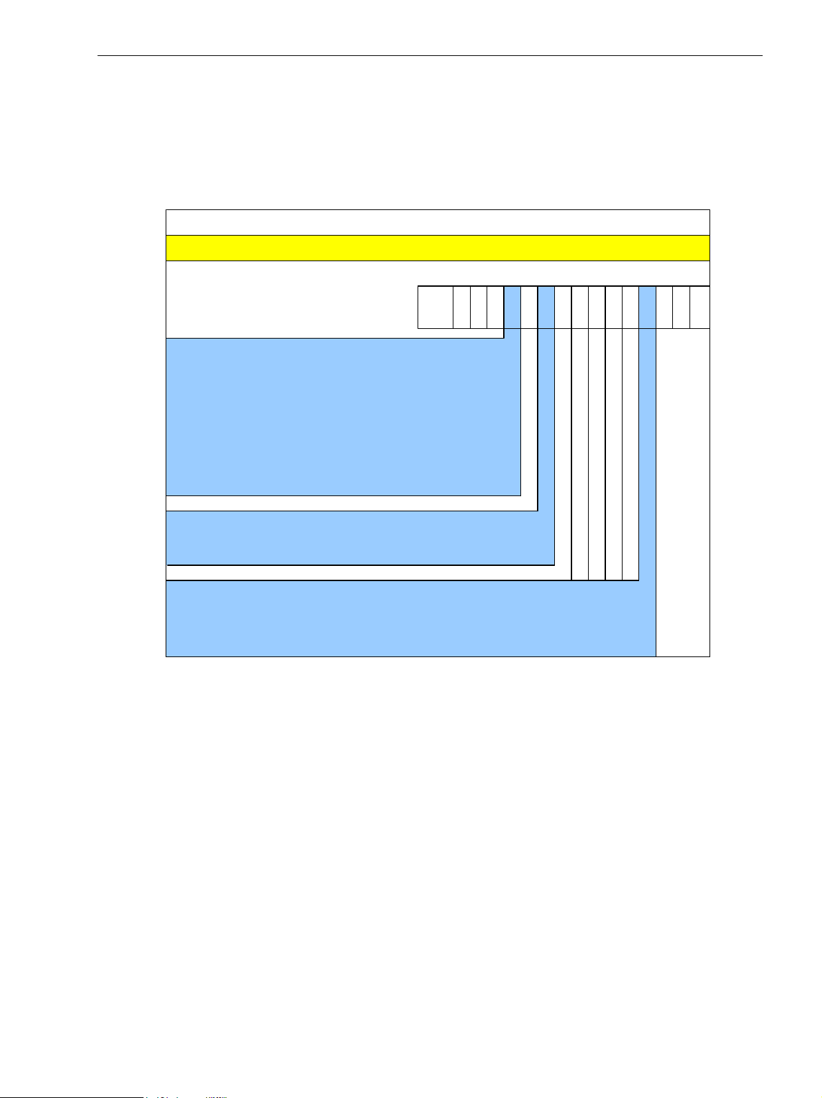
SICAM MMU can optionally be executed (according to the ordering code, refer to Figure 2-2) in the following
variants:
• Input circuits for alternating-voltage measurements:
− With voltage divider
− Galvani cally isolated voltage inputs
• Communication via Ethernet:
− With Modbus TCP protocol
− With Modbus TCP protocol and IEC 60870-5-104 protocol
SICAM MMU Version
Fig. 2-1 SICAM MMU Version
18 SICAM MMU 7KG9663, Device Manual
E50417-H1040-C514-A3, Edition 01.2016
2.2 Ordering Information, Scope of Delivery and Accessories
Description
SICAM MM U
Order No. / MLFB
Device type
DIN rail mounting unit without display, IP20
Case 96 mm x 96 mm x 100 mm
2 Binary outputs
Web server
UL Cer tifica tion
Measurements: V, I, f, P, Q, S, cos phi, energy,
harmonics
Ethernet int er f ace, connection RJ45
1 2 3 4 5 6 7 8 9 10 11 12 13 14 15 16
0AAA0
-
66
-
97KG
AC input circ ui t s
Voltage divider 1
Galvanic isolated voltage inputs 2
Ethernet i nter f ace and communi cation protocol
Modbus TCP 1
Modbus TCP and IEC 60870-5-104 4
(IEC 60870-5-104 redundant and SI CAM I/O integrat ion)
3 A0
2.2 Ordering Information, Scope of Delivery and Accessories
2.2.1 Ordering Information for SICAM MMU
Use the following ordering code to order the SICAM MMU:
2 Overview
Fig. 2-2 Ordering Code for SICAM MMU
Scope of Delivery
The delivery comprises the following components depending on the ordering code:
• SICAM MMU according to ordering code (see Figure 2-2)
• Battery (insulated in the battery compartment of the device)
• Product Information E50417-B1050-C514
E50417-H1040-C514-A3, Edition 01.2016
19SICAM MMU 7KG9663, Device Manual

2 Overview
2.2 Ordering Information, Scope of Delivery and Accessories
Accessories
The following components are optionally available:
• Device Manual E50417-H1040-C514 (download available at www.powerquality.de)
• Replacement sockets for alternating-voltage inputs
Order via:
Phoenix Contact GmbH & Co. KG
Item number: 1700734
Product name: GMSTB 2,5 HCV/ 4-ST-7,62 BK TS
Minimum order quantity: 50 pieces
• Ethernet patch cables:
Table 2-1 Ethernet Patch Cable (double shielded (SFPT), LAN connector plugs on both sides)
Cable Length Order No.
0.5 m 7KE6000-8G-D00-0AA5
1.0 m 7KE6000-8G-D00-1AA0
2.0 m 7KE6000-8G-D00-2AA0
3.0 m 7KE6000-8G-D00-3AA0
5.0 m 7KE6000-8G-D00-5AA0
10.0 m 7KE6000-8G-D01-0AA0
15.0 m 7KE6000-8G-D01-5AA0
20.0 m 7KE6000-8G-D02-0AA0
20 SICAM MMU 7KG9663, Device Manual
E50417-H1040-C514-A3, Edition 01.2016
2.2 Ordering Information, Scope of Delivery and Accessories
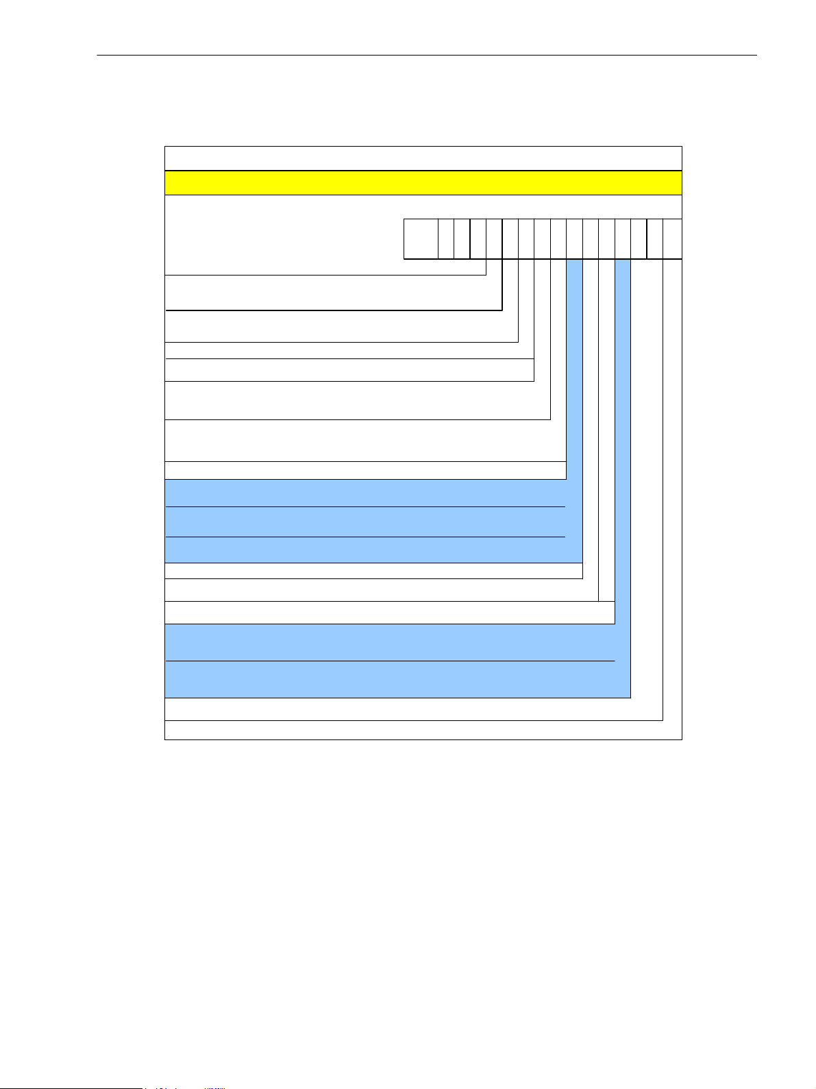
Description
SICAM I /O Unit
Order No. /MLFB
SICAM I /O Unit, integrated electr ical
Ethernet inter f ace, connection RJ45
Device type
Case 96 mm x 96 mm x 100 mm
1 2 3 4 5 6 7 8 9 10 11 12 13 14 15 1 6
1AA0JJ 0
-
673
-
57XV
Inputs and output s
3 Binary inputs with adjustable threshold voltage ,
3 Relay outputs (2 NO, 1 CO)
3 Binary inputs with adjustable threshold voltage ,
3 Relay outputs (2 NO, 1 CO)
Serial i nter f ace and communi cation protocol
Without ser ial comm unication
RS485 – Modbus RTU, I/O m irr or
FO 820 nm – Modbus RTU, I/O mir ror
0
1
Protecti on class
Snap-on mounting unit, protect ion class IP20
Communicati on int er f ace and communicat i on prot ocol
Ethernet int er f ace with Modbus TCP/UDP or
I/O mirror
Ethernet int er f ace with Modbus TCP/UDP,
I/O mir ror, or IEC 61850 (GOO SE, MMS, Reporting)
Features
Integr at ed Ether net switch
2
1
2
2.2.2 Ordering Information for Subdevice SICAM I/O Unit 7XV5673
Use the following ordering code to order the subdevice SICAM I/O Unit 7XV5673:
2 Overview
Fig. 2-3 Ordering Code for Subdevice SICAM I/O Unit 7XV5673
Accessories
The following components are optionally available:
• Device manual E50417-H1040-C484 ((download available at http://www.siprotec.de)
• Y cable, order number 7KE6000-8GD00-0BA2
E50417-H1040-C514-A3, Edition 01.2016
21SICAM MMU 7KG9663, Device Manual

2 Overview
2.2 Ordering Information, Scope of Delivery and Accessories
22 SICAM MMU 7KG9663, Device Manual
E50417-H1040-C514-A3, Edition 01.2016

3 Device Design
3.1 Mechanical Design 24
3.2 Electrical Design 25
E50417-H1040-C514-A3, Edition 01.2016
23SICAM MMU 7KG9663, Device Manual
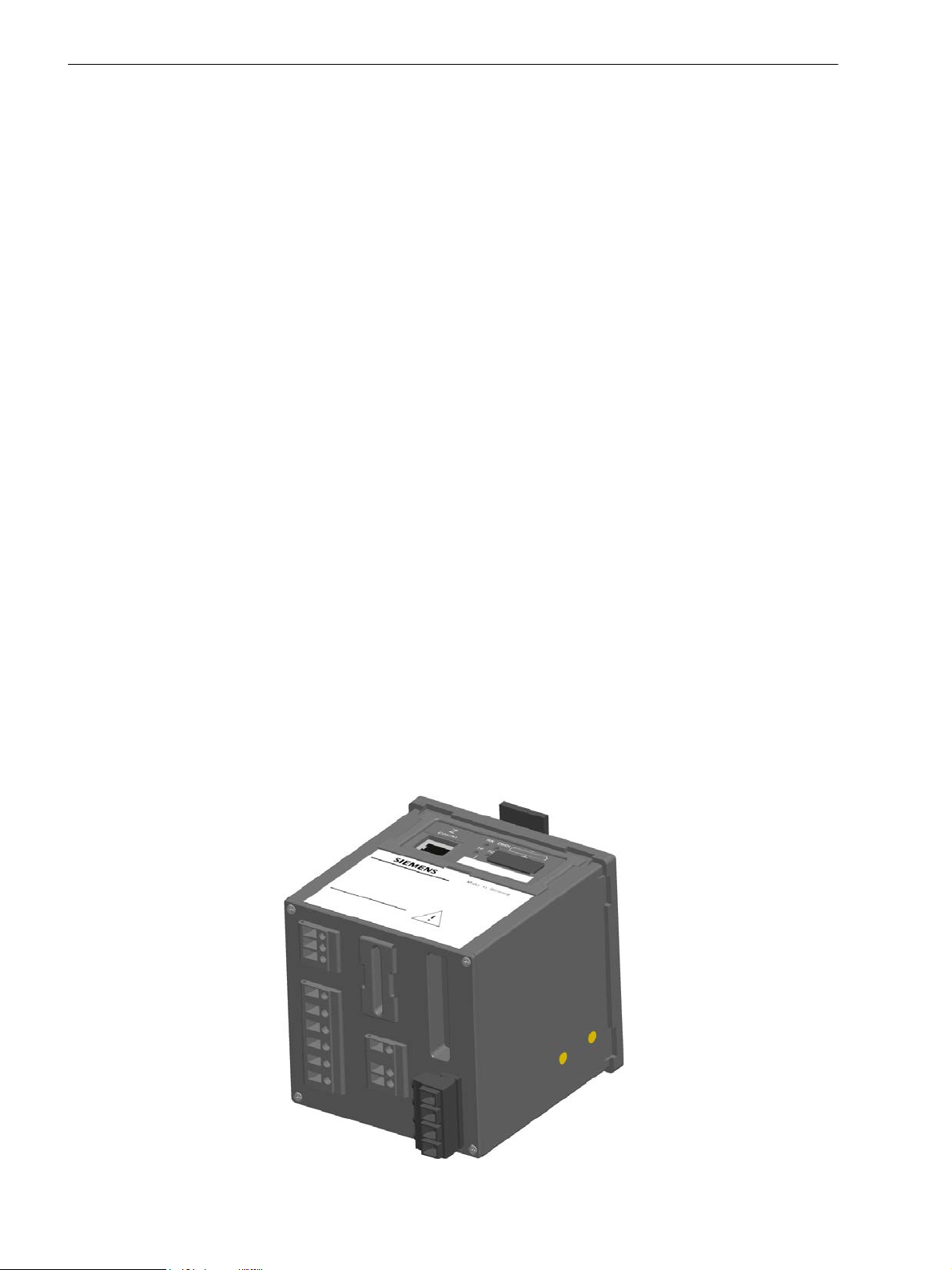
3 Device Design
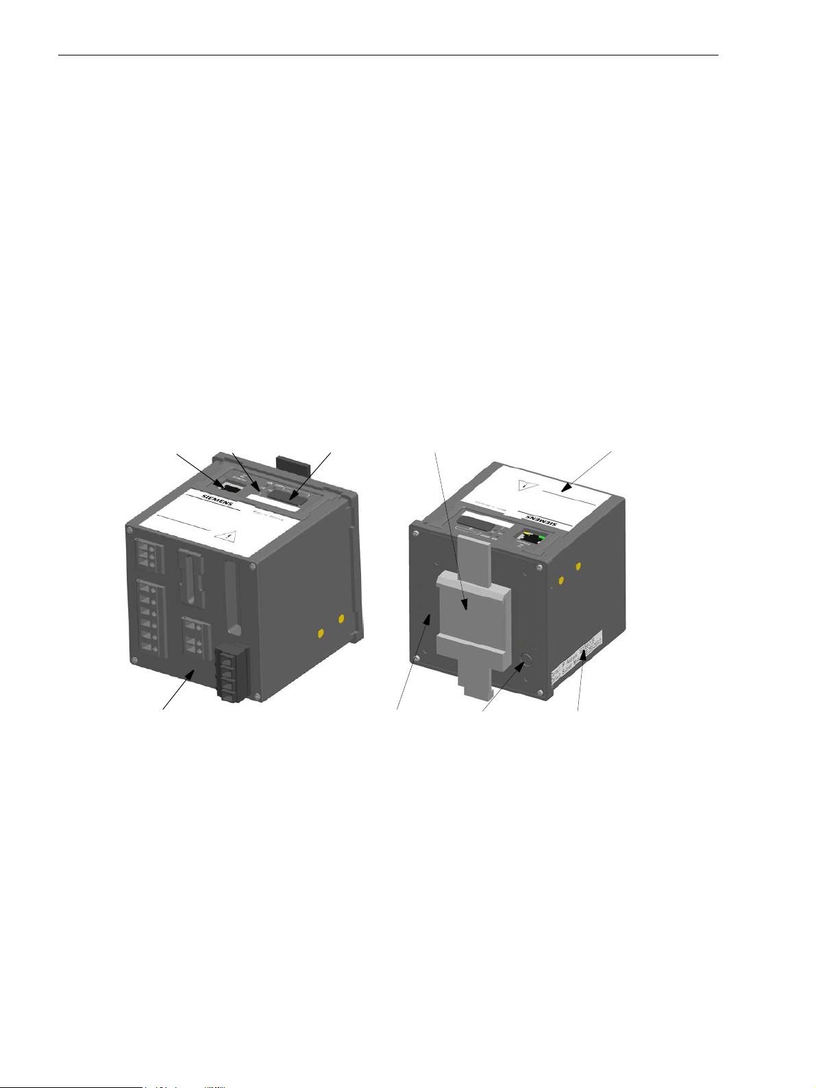
Cover of battery
4LEDs
Terminal side DIN rail side
Mount for snap-in unit
IP-Addr. Default IP address
RJ45 with
Label
Default subnet mask
compartment
2LEDs
push-button
3.1 Mechanical Design
3.1 Mechanical Design
The electrical modules are installed in a plastic case with the dimensions 96 mm x 96 mm x 100 mm
(W x H x D). The case is prepared for mounting on a DIN rail.
The top side of the device accommodates the RJ45 Ethernet connector with 2 LEDs and 4 additional LEDs. At
the cover of the battery compartment there is a labeling strip for the configurable LEDs H1/H2 and a battery
symbol that indicates the po l a ri ty. Th e l a be l i s al so located on the top side and provides among other information the most important rated data of the device. A lithium battery is located under the removable cover of the
battery compartment.
The terminals for connecting all inputs and outputs, for the supply voltage and the protective grounding are located on the terminal side. The number, type and position of the terminals differs according to device version
and is described in detail in chapter 5.3.
The snap-in unit is mounted in the center of the DIN rail side. The IP Addr. push-button is located in the lower
right corner of the DIN rail side. Pressing it (> 3 s) activates the factory-set default IP address. The default IP
address and the default subnet mask are imprinted on the side panel.
Fig. 3-1 Design of the
24 SICAM MMU 7KG9663, Device Manual
SICAM MMU
E50417-H1040-C514-A3, Edition 01.2016
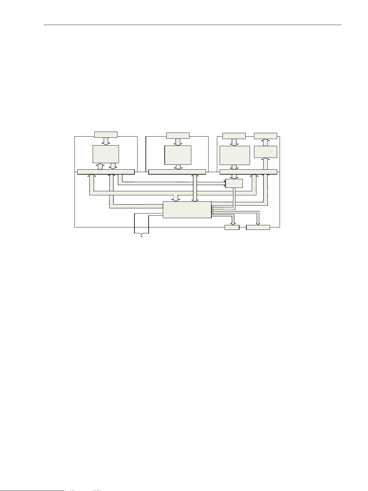
3.2 Electrical Design
4 x AC
voltage
measuring
inputs
Terminal
Power
supply
Terminal
3 x AC
current
measuring
inputs
Terminal
2 x Binary
outputs
Terminal
ADC
DSP
LED Ethernet
IP Addr. push-button
SICAM MMU contains the following electrical modules dependin g on the device version:
• Digital signal processor (DSP)
• 4 inputs for AC voltage measurements
• 3 inputs for AC current measurements
• 2 binary outputs
• Supply voltage
3 Device Design
3.2 Electrical Design
Fig. 3-2 Block Diagram SICAM MMU
E50417-H1040-C514-A3, Edition 01.2016
25SICAM MMU 7KG9663, Device Manual

3 Device Design
3.2 Electrical Design
26 SICAM MMU 7KG9663, Device Manual
E50417-H1040-C514-A3, Edition 01.2016

4 Measurands and Characteristics
4.1 Measurands 28
4.2 Display of Measurands 35
4.3 Calculation of the Measurands 37
E50417-H1040-C514-A3, Edition 01.2016
27SICAM MMU 7KG9663, Device Manual

4 Measurands and Characteristics
4.1 Measurands
4.1 Measurands
4.1.1 Measurands in 1-phase Systems
The SICAM MMU can measure or calculate the following measurands in 1-phase systems. Chapter 4.1.3 contains a detailed list of all measurands.
Measured and Calculated Quantities
The operational quantities AC voltage V
erational measurands, power and energy quantities are calculated from the measured operational quantities.
Operational Measurands
SICAM MMU measures or calculates the following operational quantities:
• AC voltage V
• Voltage harmonic: HVa
• AC current I
• Current harmonic: HIa
• Active power factor cos ϕ: cos ϕ (a)
• Power factor PF: PFa
• Phase angle ϕ: ϕa
• Frequency (power frequency): f
Power Quantities
SICAM MMU calculates the following power values from the measured operational quantities:
• Active power P: Pa
• Reactive power Q: Qa
• Apparent power S: Sa
AC current IP and frequency f are measured directly. All other op-
ph,
(mains voltage referred to the neutral conductor/protective ground N; RMS value): Va
ph
(current through the conductor, RMS value): Ia
P
Energy Quantities
SICAM MMU calculates the following energy values from the measured opera tional quantities:
• Active energy WP: WPa (supply and demand)
• Reactive energy WQ: WQa (inductive and capacitive)
• Apparent energy WS: WSa
28 SICAM MMU 7KG9663, Device Manual
E50417-H1040-C514-A3, Edition 01.2016

4.1.2 Measurands in 3-wire and 4-wire Networks
SICAM MMU can measure or calculate the following quantities in 3-wire and 4-wire networks (delta and star
connection): Chapter 4.1.3 contains a detailed list of all measurands.
Measured and Calculated Quantities
4 Measurands and Characteristics
4.1 Measurands
The operational quantities AC voltage V
conductor V
N
quantities are calculated from the measured operational quantities.
Operational Measurands
SICAM MMU measures or calculates the following operational quantities:
• AC voltage phase-neutral conductor (neutral conductor connected to protective ground; star connection)
V
: Va, Vb, Vc
ph-N
• AC voltage phase-phase (delta connection) V
• Voltage harmonics HV
•AC current I
• Current harmonics HI
• AC voltage across the neutral conductor: V
• Unbalanced voltage: V
• Unbalanced current: I
• Mean value of the 3 phase voltages: V
• Current in neutral conductor: I
• Mean value of the 3 phase currents: I
• Active power factor cos ϕ: cos ϕ (a), cos ϕ (b), cos ϕ (c), cos ϕ
• Power factor PF: PFa, PFb, PFc, PF
• Phase angle ϕ: ϕa, ϕb, ϕc, ϕ
• Angle between the phase-ground voltages a-b and a-c: ϕab, ϕac
• Frequency (power frequency): f (see Table 4-5)
, AC voltage V
ph-N
, AC current Iph, AC voltage across the neutral
ph-ph
and frequency f are measured directly. All other operational measurands, power and energy
: Vab, Vbc, Vca
ph-ph
: HVa, HVb, HVc
ph
(current through the conductor): Ia, Ib, Ic
P
: HIa, HIb, HIc
ph
N
unbal
unbal
avg
N
avg
Power Quantities
SICAM MMU calculates the following power values from the measured operational quantities:
• Active power P: Pa, Pb, Pc, P
• Reactive power Q: Qa, Qb, Qc, Q
• Apparent power S: Sa, Sb, Sc, S
Energy Quantities
SICAM MMU calculates the following energy values from the measured operational quantities:
• Active energy WP: WPa, WPb, WPc, WP (for supply and demand respectively)
• Reactive energy WQ: WQa, WQb, WQc, WQ (inductive and capaciti ve respectively)
• Apparent energy WS: WSa, WSb, WSc, WS
E50417-H1040-C514-A3, Edition 01.2016
29SICAM MMU 7KG9663, Device Manual

4 Measurands and Characteristics
4.1 Measurands
4.1.3 Measurands Depending on the Connection Type
4.1.3.1 Operational Measurands
Table 4-1 Measurands for the Operation in Power Systems
Measurand Circuit 1-phase
System
Balanced
(1I)
3-wire Network
(delta)
Unbalanced
(3I)
Unbalanced
(2I)
4-wire Network
Balanced
(1I)
(star)
Unbalanced
(3I)
AC Voltage
Va a-N x x x
Vb b-N x
Vc c-N x
Vab a-b x x x x
Vbc b-c x x x x
Vca c-a x x x x
V
N
a, b, c x
Vavg a, b, c Σ Vph/3 Σ Vph/3 Σ Vph/3 a-N Σ Vph/3
Vunbal a-b, b-c,
xx x x
c-a
HVa a-N x x x
HVb b-N x
HVc c-N x
AC Current
Ia a x x x x x x
Ib b x x x
Ic c x x x
I
N
a, b, c x x
Iavg a, b, c x x Σ Iph/3
Iunbal a, b, c x x x
HIa a x x x x x x
30 SICAM MMU 7KG9663, Device Manual
E50417-H1040-C514-A3, Edition 01.2016
 Loading...