

Siemens SICAM MIC System Description

MC6-054-2.00
SICAM RTUs
SICAM MIC
System Description
Preface, Table of Contents
Introduction
1
System Overview
2
Function Packages
3
Ambient Conditi ons
4
System Components and Technical Data
5
Order Informati on
A
Glossary

Siemens AG Order no.: MC6-054-2.00
Note
Please take notice of the notes and warnings f or your safety in the preface.
Disclaimer of Liability
Although we have carefully checked the contents of this publication
for conformity with the hardware and software d escribed, we cannot
guarantee complete conformity since errors cannot be excluded.
The information provided in this manual is checked at regular
intervals and any corrections that might become necessary are
included in the next releases. Any suggestions for improvement are
welcome.
Subject to change without prior notice.
Document Label: SIC1703-SYBSICAMMIC-ENG_V2.00
Release Date: 2014-07-23
Copyright
Copyright © Siemens AG 2014
The reproduction, transmission or use of this document or its
contents is not permitted without express written authority. Offenders will be liable for damages. All rights, including rights created by
patent grant or registration of a utility model or design, are reserved.

SICAM RTUs, SICAM MIC System Description 3
MC6-054-2.00, Edition 07.2014
Preface
Purpose of this manual
This manual describes the characteristics and functions of the system SICAM MIC. It contains
· Fields of application and advantages of the system
· Configuration possibilities
· Functional overviews
· Technical specifications
· Order information
Target Group
The document y ou are r eading right now is addressed to users, who ar e in cha rge of the f ollowing engineering tasks:
· Evaluation of the suitability of the system
· Evaluation of the module specifications
· Evaluation of quotation criteria, such as technical specifications of the system or environ-
mental conditions
· Conceptual activities, such as design and configuration
Recommendations for Third-Party Products
Siemens does neither receive liability nor warr anty for recommendations which are given or
implied by this manual. For the correct and intended use of the respective product the associated technical descriptions must be paid attention to in any case.
References to Third-Party Web Sites
Siemens is not responsible for the contents of third-party websites mentioned in this document, as well as the correctness of the publications and links. For all product information the
respective manufacturer is responsib le.

Preface
4 SICAM RTUs, SICAM MIC System Description
MC6-054-2.00, Edition 07.2014
Placement into the Information Landsc ape
Document na me Item number
Folder SICAM MIC MC6-000-1
SICAM MIC User Manual DC6-058-2
SICAM TM I/O M odules DC6-041-2
SICAM RTUs IEC 60870-5-101/104 Interoperability DC0-013-2
Ax 1703 IEC 60870- 5-101/104 Interoperability DA0-046-2
Data Sheet CM-0819 MC0-043-2
Data Sheet CM-0821 MC0-031-2
Data Sheet CM-0822 MC0-033-2
Data Sheet CM-0823 MC0-035-2
Data Sheet CM-0827 MA0-025-2
Data Sheet CM-0829 MC0-045-2
Further Support
For more information, please contact our Customer Support Center:
Phone: +49 (0)180 524 70 00
Fax: +49 (0)180 524 24 71
(charges depending on provider)
e-mail: support.ic@siemens.com
The Siemens Power A cademy offers a c ompreh ensi ve program of professi onal trai ning ev ents
in the fields of power generation, distribution and tr ansmission.
Main training centers are:
Nuremberg, Germany (Head Office)
Phone: +49 911 433 7415
Fax: +49 911 433 5482
power-academy.ptd@siemens.com
Vienna, Austria
Phone: +43 51707 31143
Fax: +43 51707 55243
power-academy.at@siemens.com
Schenectady, NY, USA
Phone: +1 518 395 5005
Fax: +1 518 346 2777
pti-edpro.ptd@siemens.com
Hebburn, United Kingdom
Phone: +44 1914 953449
Fax: +44 1914 953693
pti-training.stdl.uk@siemens.com
Preface
SICAM RTUs, SICAM MIC System Description 5
MC6-054-2.00, Edition 07.2014
Notes on Safety
This manual does not constitute a complete catalog of all safety measures required for operating the equipment (module, device) in question because special operating conditions might
require additional measures. However, it does contain notes that must be adhered to for your
own personal safety and to avoid damage to property. These notes are highlighted with a
warning triangle and different keywords indicating different degrees of danger.
Danger
Means th at death, serious bodily injury or considerable propert y d amage will occur, if the appropriate
precaut ionary meas ures are not carried out .
Warning
Means th at death, serious bodily injury or considerable propert y d amage can occur, if the appropri ate
precaut ionary meas ures are not carried out .
Caution
Means th at minor bodily injury or prop ert y damage can occur, if the appropriate precautionar y measures
are not carried out.
Note
Is important infor mation abou t the produc t, the handling of th e product or the respective part of t he documentation, to which special attention is to be given.
Qualified Personnel
Commissioning and operati on of the equipment (module, device) described in this manual
must be performed by qualified personnel only. As used in the safety notes contained in this
man ual, qualified personnel are th ose persons wh o are author ized t o commissio n, release,
ground, and tag devices, systems, and electrical circuits in accordance with safety standards.

Preface
6 SICAM RTUs, SICAM MIC System Description
MC6-054-2.00, Edition 07.2014
Use as Prescribed
The equipment (device, module) must not be used for any other purposes than those described in the Catalog and the Technical Description. If it is used together with third-party devices and components, these must be recommended or approved by Siemens.
Correct and safe operation of the product requires adequate transportation, storage, installation, and mounting as well as appropriate use and maintenance.
During operation of electrical equipment, it is unavoidable that certain parts of this equipment
will carry dangerous voltages. Severe injury or damage to property can occur if the appropriate measures are not taken:
· Hazardous voltages can be present on all switching components connected to the power
supply.
· Even after the supply voltage has been disconnected, hazardous voltages can still be present in the equipment (capacitor storage).
· The limit values indicated in the manual or the operati ng instructions must not be exceeded; that also applies to testing and commissioning.
Danger
Consid er obligat or y the saf ety r ules for the accomp lishment of works at electrical plants:
1. Switch off electricity all-pole and on all sides!
2. Ensure that electricity cannot be switched on again!
3. Double check that no electrical current is flowing!
4. Discharge, ground, short circuit!
5. Cover or otherwise isolat e componen ts that are s till electr ically ac tive!

SICAM RTUs, SICAM MIC System Description 7
MC6-054-2.00, Edition 07.2014
Table of Contents
1 Introduction ................................................................................................................. 11
1.1 Compact Teleco ntrol Syste m SICAM MIC ....................................................... 1 2
1.2 SICAM MIC – The Advanta ges ....................................................................... 14
1.2.1 Features .................................................................................................... 14
1.2.2 Various Fields of Appl ication ...................................................................... 1 4
2 System Overv iew ........................................................................................................ 1 5
2.1 Performance ................................................................................................... 16
2.2 Mechan ical Structure ...................................................................................... 17
2.3 Architecture .................................................................................................... 19
2.3.1 Powe r Supply Module ................................................................................ 19
2.3.2 Master Control Element ............................................................................. 20
2.3.3 Periphe ral Element .................................................................................... 22
2.3.3.1 I/O Modules .......................................................................................... 23
2.3.3.1.1 Configu ration Notes ......................................................................... 24
2.3.3.2 TM Periphe ral Bus ................................................................................ 25
2.4 Commun ication .............................................................................................. 26
2.4.1 Proces s Communication and Engineering .................................................. 26
2.4.2 Transmis sion Modes.................................................................................. 27
2.4.3 Configurations ........................................................................................... 2 8
2.4.3.1 Multi-Po int Traffic.................................................................................. 29
2.4.3.1.1 Dial-Up Traffic .................................................................................. 30
2.4.3.1.2 LAN/WAN ........................................................................................ 32
2.4.3.1.3 Internet/GPRS ................................................................................. 3 3
2.5 Engineering .................................................................................................... 34
2.5.1 Integra ted Webser ver for Simple Applications ............................................ 3 4
2.5.2 TOOLBOX II .............................................................................................. 34
3 Functi on Packa ges...................................................................................................... 35
3.1 System Service s ............................................................................................. 36
3.2 Telecontro l ..................................................................................................... 37
3.3 Automation ..................................................................................................... 38
4 Ambie nt Conditi ons .................................................................................................... 39
4.1 Protect ion Type .............................................................................................. 4 0
4.2 Mechan ical Ambien t Condit ions ...................................................................... 41
4.3 Climatic Ambient Condit ions ........................................................................... 42
4.4 Electro magnetic Compatibi lity ......................................................................... 43
4.4.1 System Properties ..................................................................................... 43
4.4.2 Powe r Supply DC ...................................................................................... 44

Table of Contents
8 SICAM RTUs, SICAM MIC System Description
MC6-054-2.00, Edition 07.2014
4.4.3 Digital and Analog I/Os .............................................................................. 45
4.4.4 Serial Commun icat ion V.24/V.2 8 ............................................................... 45
4.4.5 Commun ication LAN .................................................................................. 46
5 System Comp onents and Tech nical Data .................................................................. 47
5.1 Mechan ical Design ......................................................................................... 48
5.2 Powe r Supply Modules ................................................................................... 49
5.2.1 PS-6630 .................................................................................................... 49
5.2.2 PS-6632 .................................................................................................... 50
5.3 Master Contro l Modules .................................................................................. 5 1
5.3.1 CP-6020 .................................................................................................... 51
5.3.2 CP-6040 .................................................................................................... 53
5.4 Periphe ral Ele men t and I /O Mod ules .............................................................. 5 5
5.4.1 Acquis ition and Preproces sing ................................................................... 56
5.4.1.1 DI-6100 ,DI-61 01, DI-6 104 .................................................................... 56
5.4.1.2 DI-6102 , DI-6103 .................................................................................. 57
5.4.1.3 AI-6300 , AI-6307, AI-6308 .................................................................... 58
5.4.1.4 AI-6310 ................................................................................................ 59
5.4.1.5 TE-6430 ............................................................................................... 5 9
5.4.2 Postp rocess ing and Outpu t........................................................................ 60
5.4.2.1 DO-6200 .............................................................................................. 60
5.4.2.1.1 Further Funct ions ............................................................................ 6 0
5.4.2.2 DO-6212 .............................................................................................. 61
5.4.2.2.1 Further Funct ions ............................................................................ 6 1
5.4.2.3 DO-6220 , DO-6221 , DO-6230 .............................................................. 62
5.4.2.3.1 Further Funct ions ............................................................................ 6 2
5.4.2.4 AO-6380............................................................................................... 63
5.4.3 Return Infor ma tion to Puls e Comman d As s ignmen t ................................... 64
A Order Inform ation ........................................................................................................ 67
A.1 Powe r Supply Modules ................................................................................... 68
A.2 Master Contro l Modules .................................................................................. 6 9
A.3 I/O Modules .................................................................................................... 7 0
A.4 Interface Modules ........................................................................................... 73
A.5 Accessories .................................................................................................... 74
A.5.1 Proprieta ry Modems .................................................................................. 74
A.5.2 Recommen ded Mode ms (Third-Par ty Devices) .......................................... 7 4
A.5.3 Cables and Plugs ...................................................................................... 7 5
A.1.1. Recomman ded Upstre am Power Supply Units ........................................... 76
A.5.4 SIM Card ................................................................................................... 7 7
A.5.5 Miscellan eous ........................................................................................... 7 7
A.6 Enginee ring Tools .......................................................................................... 79
A.6.1 SICAM TOOLBOX II .................................................................................. 79
A.6.1.1 Toolse ts ............................................................................................... 79

Table of Contents
SICAM RTUs, SICAM MIC System Description 9
MC6-054-2.00, Edition 07.2014
A.6.1.2 Packag es ............................................................................................. 80
A.6.2 Web Engineer ing ....................................................................................... 80

Table of Contents
10 SICAM RTUs, SICAM MIC System Description
MC6-054-2.00, Edition 07.2014

SICAM RTUs, SICAM MIC System Description 11
MC6-054-2.00, Edition 07.2014
1 Introduction
Contents
1.1 Compact Teleco ntrol Syste m SICAM MIC ....................................................... 1 2
1.2 SICAM MIC – The Advanta ges ....................................................................... 14
Introduction
12 SICAM RTUs, SICAM MIC System Description
MC6-054-2.00, Edition 07.2014
1.1 Compact Telecontrol System SICAM MIC
Compact performance
SICAM MIC (Terminal Module for microcontrol) is a low-cost, modular, telecontrol substation
and belongs to the proven SICAM RTU automation family.
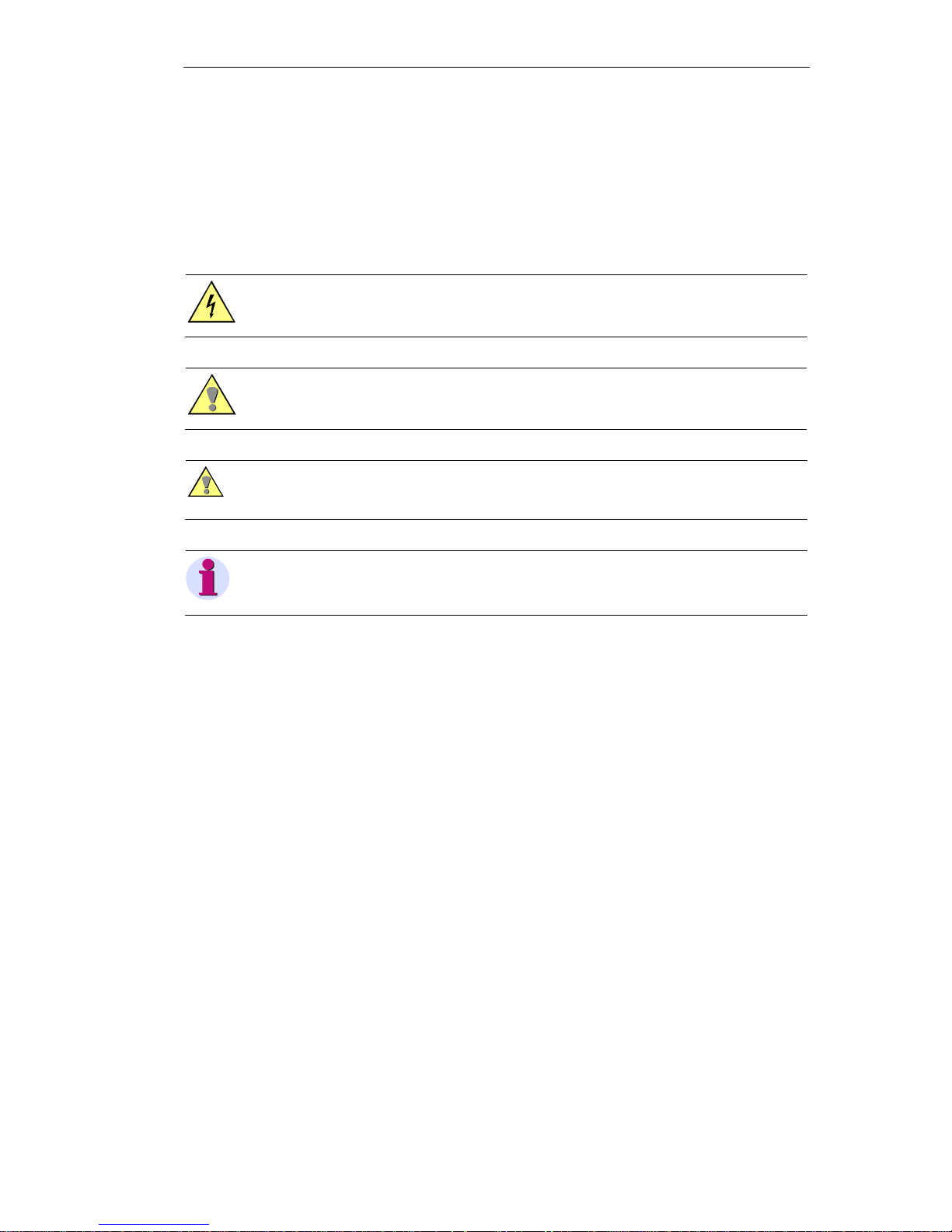
The devices consist of a master control element and various I/O modules. The master control
element serves for interfacing and supplying the I/O modules and provides a telecommunications interface in accordance with IEC 60870-5-101 for dial-up or multipoint traffic.
Alternatively, LAN/WAN communication can be used according to IEC 60870-5-104 over
Ethernet TCP/IP. All modules are designed for DIN rail mounting.
Practical engineering
Great importance was pl aced on keeping the engineering process as simple as possible.
That’s why the master control element has an integrated Web server for configuration, diagnostics and testing, so no special tools or additional licenses are needed. The tool is already
integrated in SICAM MIC and is operated with a standard Web browser.
Alternatively, it is also possible to use SICAM TOOLBOX II, the integrated engineering tool for
the entire SICAM RTU family.
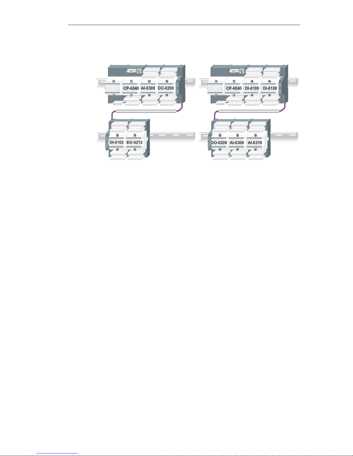
Universal assembly
The modules are simply snapped onto a 35-mm DIN rail. Up to eight I/O modules can be
mounted in addition to the power supply module and the master control. The extension cable
CM-6810 enables the I/O modules to be distributed between two DIN rails. The advantage of
this is that even with limited space there is still adequate room for the modules.

Introduction
SICAM RTUs, SICAM MIC System Description 13
MC6-054-2.00, Edition 07.2014
Total application, fully flexible
· Thanks to its node functionality, the SICAM MIC has many different potential appl ications,
for example as an ordinary telecontrol substation with any kind of communication to a control center.
· If SICAM MIC does not offer adequate signal scope, additional SICAM MIC systems can
be readily connected.
· Fr eely pro gramm abl e applic atio n program s for local contr ol functi ons compl ete the allround versatility of the SICAM MIC.
· Th e SICAM MI C can be used optio nal ly in mult ipo i nt or dial- up traf fi c, but al so over
LAN/WAN networks. Transmission conforms to IEC 60870-5-101 or IEC 60870-5-104.
Good connections to the control center
· Multipoint traffic
External data transmission equipment can be connected via the V.28 interface.
· Dial-up traffic
A wide range of connection-oriented transmission media (analog, ISDN, GSM, TETRA) is
supported as standard.
· LAN/WAN
IEC 60870-5-104-compliant transmission based on Ethernet TCP/IP is used for communi-
cation.

Introduction
14 SICAM RTUs, SICAM MIC System Description
MC6-054-2.00, Edition 07.2014
1.2 SICAM MIC – The Advantages
1.2.1 Features
Your advantages at a glance:
· Integrated node functionality for interfacing additional equipment via various protocols
· Communication via IEC 60870-5-101/104
· Sim pl e configur ati on via W eb brow ser, wit hout speci al tools or licens es
· Configuration, di agnostics and testing via integrated Web server
· Alternatively, the engineering process can also be carried out with SICAM TOOLBOX II
· Integrated remote mai ntenance, remote diagnostics and remote parameterization
· Appl icati on programs for l ocal contr ols and int erlo cks
· Plug & Play for start-up and servicing through use of flash card or SIM card for data stor-
age
· Exchange of modules without need for a tool
· D irect connecti on of the pr ocess c ables
· Mounting on 35 mm DIN rail
· Temperature range –25°C to +70°C
1.2.2 Various Fields of Application
The universal system SICAM MIC is ideally suitable for applications in:
· Hydropower plants
· W ind farms and s olar plants
· Railway power supplies and tunnels
· Electrical distribution substations/secondary substations
· Gas distribution stations
· Pipelines
· Bui lding protect ion and al arm sensors

SICAM RTUs, SICAM MIC System Description 15
MC6-054-2.00, Edition 07.2014
2 System Overview
Contents
2.1 Performance ................................................................................................... 16
2.2 Mechan ical Structure ...................................................................................... 17
2.3 Architecture .................................................................................................... 19
2.4 Commun ication .............................................................................................. 26
2.5 Engineering .................................................................................................... 34

System Overview
16 SICAM RTUs, SICAM MIC System Description
MC6-054-2.00, Edition 07.2014
2.1 Performance
· Modular structured system
· Single processor solution
· Combined automation and telecontrol function
· Loadable firmware
· Offline and online parameter-settable
· Saving of firmware and application data on replaceable SIM card
· Com muni cat ion wit h other automat ion unit s accordi ng to IEC 6 087 0-5- 101 (mult ipo int traf-
fic, dial-up traffic, point-to-point traffic)
· Communication with control center according to IEC 60870-5-104 (Ethernet TCP/IP) or
according to IEC 60870-5-101 (dial-up traffic )
· Standard protocols according to IEC 60870-5-101/104
· Spontaneous (acknowledged) transmission
· LED signaling on the front panel of the modules
System Overview
SICAM RTUs, SICAM MIC System Description 17
MC6-054-2.00, Edition 07.2014
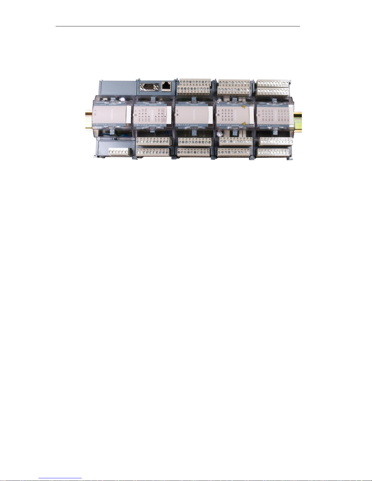
2.2 Mechanical Structure
Installation takes place on a 35 mm DIN rail that is mounted horizontally or vertically on a vertical standing rack. The sequence of modules from left to right or top to bottom is prescrib ed
as follows:
· 1 power supply module (optionally 2 for redundancy)
· 1 master control module
· Optionally up to 8 I/O modules
The electrical connection of the modules with the power supply takes place during the process
of latching together, whereby each module can be individually replaced.
Standard Structure
8 I/O-Modules
max.
Master Control Module
Power Su pply Module
System Overview
18 SICAM RTUs, SICAM MIC System Description
MC6-054-2.00, Edition 07.2014
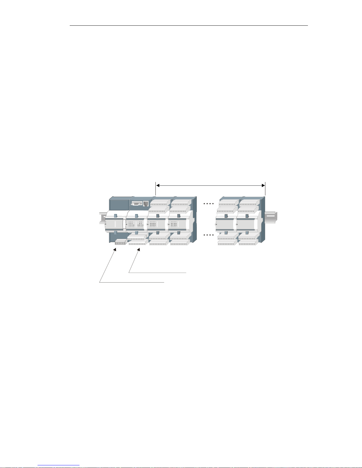
Redundant Power Supply (not suitable for power enhancement)
2-Line Arrangement
8 I/O-Mo du les
max.
Master Control Module
Power Su pply Module
Power S upply Module
in total m ax .
8 I/O modules
Maste r control module
Power supply module

System Overview
SICAM RTUs, SICAM MIC System Description 19
MC6-054-2.00, Edition 07.2014
2.3 Architecture
2.3.1 Power Supply Module
The supply of SICAM MIC is carried out by a power supply module.
The power supply module provides the operating voltage
for the master control module and for the optional I/O
modules.
It provides also the operating voltage for the transmission
equipment for multi-point traffic and dial-up traffic.
Features and Functions
· Installation on DIN rail
· Input voltages alternatively
─ 24…60 VDC
─ 110…220 VDC
· System voltage output U1 5.1 VDC, max. 8 W
· System voltage output U2 switchable
─ 5.2 VDC, max. 2.5 W or
─ 10 VDC, max. 2.5 W
· Environmental conditions according to EMC+
· Removable screw terminals
· Supervision of the output voltage
· Can be connected in parallel for redundancy
· Function indication via LED
Product Overview
Type Designation Power
PS-6630 Power supply module 24…60 VDC (EMC+) 8 W
PS-6632 Power supply module 110…220 VDC (EMC+) 8 W

System Overview
20 SICAM RTUs, SICAM MIC System Description
MC6-054-2.00, Edition 07.2014
2.3.2 Master Control Element
The master control element is the heart of the system SICAM MIC. The hardware of the master control element is the master control module
, and its functionality is provided by me ans of
a loadable and param eter-sett able firmw are.
On the master control module CP-6020 res ide an interface for the communicati on (serial ), di gital inputs and
outputs, as wel l as a lighted di splay.
On the master control module CP-6040 resides additionally an interface for the communication via Ethernet.
The master control element contains all the central fun ctions for processing and communicati on, and it provides the parameter-settable telecontrol function and the open-/closed-loop func-
tion.
Furthermore, the master control element is able to store events in an a rchive (DEAR) in case
of a communication fault. After elimination of the fault the superior control system can demand
the archive of the master control element. By means of this function, a possible data loss will
be prevented.

System Overview
SICAM RTUs, SICAM MIC System Description 21
MC6-054-2.00, Edition 07.2014
Features and Functions
· Installation on DIN rail
· 6 digital inputs
─ One common return
─ Signal voltage 24…60 VDC
─ The states of the inputs are indicated by LEDs
· 2 relay outputs
─ 1 command output
─ 1 selectable output (command output, watchdog indication or error indication)
─ With command output, the state of the output is i ndicated by LED
· In addition up to 8 I/O modules
· C ommuni cation altern ativel y via the fol lowin g inter faces :
─ Ethernet (TCP/IP) for LAN/W AN connections acc. to IEC 60870-5-104 (only CP-6040)
─ RS- 23 2 for m ul ti- p oi n t or dial - up t r aff ic ac c . to IEC 608 7 0- 5- 10 1 wi t h an exter na l d at a
transmission facility
· Parameter settable telecontrol functions with or without tim e tagging
· Central processing functions
· Applicati on program for open-/closed-loop control functions
· Decentral archive (DEAR)
· Engineering, diagnostic, and test using webbrowser
· Storage of parameters and application program on SIM card
· Loadable firmware
· Function and failure indication via LED
· Power supply 24 VDC up to 220 VDC (depending on power suppl y module)
Product Overview
Type Designation Power
CP-6020 M aster contr ol module V. 28, 8 Modu les 800 mW
CP-6040 M aster control module ET10T X/V.28, 8 modules 800 mW
CPC60 Firmware Central Processing and Communication
SIM card Memory card f or applicati on data and f irmwar e

System Overview
22 SICAM RTUs, SICAM MIC System Description
MC6-054-2.00, Edition 07.2014
2.3.3 Peripheral Element
The virtual peripheral element serves for the acquisition or output of process signals. It performs the process-compliant adaptation, monitoring and processing of the process signals at
each point of entrance or exit of the system.
The hardware for the peripheral element is integrated on the master control module, and its
functionality is provided by means of a loadable and parameter-settable firmware.
Features
· Support of up to 8 I/O modules
· Acquisition and preprocessing of process data according to IEC 60870-5-101/104 with and
without time tag
─ Single-point and double-point information items
─ Count pulses
─ Actual values
· Postprocessing and output of process data according to IEC 60870-5-101/104
─ Single-point information items
─ Single-point and double-point commands
─ Setpoint commands
· Sec ur ed dat a excha nge bet ween t he I/O mo dul es and the mast er contr ol el em ent vi a the
TM bus
· Supervision of the I/O modules and failure processing
· Fau lt displ ay via LED on the m ast er contr ol elemen t
Product Overview
Type Designation
USIO60
*)
FirmwareUniversal Signal Input and Output(process-technical
parameters)
USIO61
*)
FirmwareUniversal Signal Input and Output (process-technical
parameters incl. checked command output)
*)
only available for TO OLBOX II; otherwis e part of f irmwar e CPC60

System Overview
SICAM RTUs, SICAM MIC System Description 23
MC6-054-2.00, Edition 07.2014
2.3.3.1 I/O Modules
The optional I/O modules support the peripheral element with the process data input and output.
The connection of the process signals (I/Os) happens by
means of r emovable s crew t erminals. The screw terminals are enclosed with each I/O module.
When modules are exchanged no connections need to
be detached, since the screw terminals carry the wiring.
Thereby the assembly effort required for the connection is
reduced to a minimum.
Further, a status display resides on the I/O modules.
Features
· Installation on DIN rail
· Acquisition of process signals and preprocessing by means of hardware
─ binary inputs
─ analog inputs (currents, voltages, temperatures)
· Output of process signals and postprocessing by means of hardware
─ binary outputs
─ analog outputs (currents and voltages)
· Status display for binary signals
· Function display via LED
Product Overview
Type Designation Power
DI-6100 Binary input 2x8, 24…60 VDC 170 mW
DI-6101 Binary input 2x8, 110/220 VDC 170 mW
DI-6102 Binary input 2x8, 24…60 VDC 1 ms 170 mW
DI-6103 Binary input 2x8, 110/220 VDC 1 ms 170 mW
DI-6104 Binary input 2x8, 220 VDC 170 mW
DO-6200 Binary output transistor 2x8, 24…60 VDC 600 mW
DO-6212 Binary output relays 8x 24…220 VD C/230 VAC 800 mW
DO-6220 Checked comm and output bas e module 560 mW
DO-6221 Checked comm and ou tput base module meas u rement 1.38 W
DO-6230 Checked comm and output relay module 130 mW
AI-6300 Analog Inp ut 2x2 ±20 mA/ ±10 V 480 mW
AI-6307 Analog Input 2x2 ±2.5 mA/±5 mA 480 mW
AI-6308 Analog Input 2x2 ±1 mA/± 2 mA/±10 V 480 m'W
AI-6310 Analog Inp ut 2x2 Pt10 0/N i100 480 mW
AO-6380 Analog Output 4x ±20 mA/±10 mA/±10 V 1.9 W
TE-6420 Speed Measurem ent 2x2 5 VDC/24 VDC/NAMUR 790 mW

System Overview
24 SICAM RTUs, SICAM MIC System Description
MC6-054-2.00, Edition 07.2014
2.3.3.1.1 Configuration Notes
Common Rules
With use of the I/O modules please pay attention to the following notes:
· Up to 8 I/O-modules can be equipped additionally to the master control module, as long as
─ the total power of the I/O-modules does not exceed 7,0 W
─ the total power of all modules - including supplied m odem and bus interface modules -
does not exceed the available power of the power supply module
· Optional use of the CM-6810 (TM I/O-Modul es Extension Cable)
· AO modules must be equipped at the first slots (up to 3 pieces possible; with 2-line ar-
rangement with CM-6810 only in the first line permitted)
· The mixture of current and voltage on the same AI module is not possible
· Th e mixt ur e of binary inf o rmati o n and puls e comman ds on the same DO modul e is not
possible
Rules for the Checked Command Output
With use of the option "checked command output" (only with firmware USIO61) the following
rules ar e to be considered:
· Only 1 command output basic module may be connected, alternatively
─ DO-6220, command output according to IC1
─ DO-6221, command output according to RC1
· The command output via DO-6220 or DO-6221 wi thout a DO-6230 i s not possible
· Up to 7 command output relay modules DO-6230 may be connected
· The command output via DO-6230 without a DO-6220 or DO-6221 is not possible
· On a DO-6230 ei ther 1-, or 1.5- or 2-pole impulse commands can be assigned (mixture on
the same module is not permitted)
· Additionally, further DO module types can be used
· with param erization with the SICAM TOOLBOX II, the I/O modules DO-6220, DO-6221
and DO-6230 must be configured underneath the virtual system element USIO61
Rules for the Return Information to Pulse Command Assignment
With use of the option "return information to pulse command assignment " (only with firmware
USIO61) the following rules are to be considered:
· W ith the par amet er- set tab le assi gnm ent the sequ ence of DI modul es and DO modul es is
arbitrary
· Wi th the f ixed assi gnm ent respect iv ely after a m odul e DI-610 x a module DO-62xx (refer to
5.4.3
, Retu rn Informa tion to Pulse Command As signment ) must be equipped
System Overview
SICAM RTUs, SICAM MIC System Description 25
MC6-054-2.00, Edition 07.2014
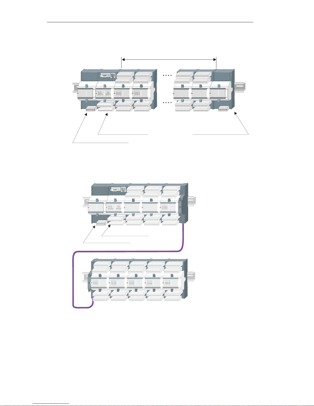
Examples for the 2-Line Arrangement
2.3.3.2 TM Peripheral Bus
The TM bus serves for the power supply of the individual modules and for the communication
of the I/O modules with the master control module. The communication takes place in the
master/slave process, wherein the I/O modules are the slaves.
The I/O modules are automatically addressed on the TM bus based on the sequence of physical fitting. The I/O module connected directly to the peripheral control module has the least
significant address.
The I/O modules are checked cyclically for functioning via the TM bus. A failure is detected after max. 200 ms. The "RY" LED goes out on the corresponding I/O module.

System Overview
26 SICAM RTUs, SICAM MIC System Description
MC6-054-2.00, Edition 07.2014
2.4 Communication
2.4.1 Process Communication and Engineering
Via the communication interface(s), the master control element can communicate with any
sup erior or subordi nate autom ation unit using an external data transmission facility, or directly
via LAN/WAN.
Master Control Interface Remarks
CP-6020/CPC60 RS-232
*)
Process communication an d engineering use the serial
interface exclusively, and t herefore are not available simultaneously
CP-604 0/C PC60
· RS-232
· Ethernet LAN
Process communication is not available si multaneously
using both interfaces
*)
with supply for external modem
The following transmission facilities can be supplied directly from the power supply module using a special cable.
Type Designation Power (typ.) Supply
1)
CE-0700 V.23 leased line modem 400 mW 5 V
CE-0701
2)
VFT channel modem 2 W 5 V
MODEM ANALOG Analog modem for d ial-up traffic 35 mW 10 V
MOD EM GSM Dual band GSM mod em 30 0 mW 10 V
1)
s witchabl e by means of T M bus message to th e power supply module
2)
withdrawn

System Overview
SICAM RTUs, SICAM MIC System Description 27
MC6-054-2.00, Edition 07.2014
2.4.2 Transmission Modes
Depending on master control module there are different communication methods available:
· Multi-point traffic
· Dial-up traffic
· Communication via LAN/WAN
· Communication via Intranet/GPRS
Feat ures and tr ansmi ssio n facil iti es wit h pre-defined settin gs:
Type Features Transmission Facilities
Multi-Point Traffic
· Unbalanc ed interchang e circ uit
(V.24/V.28) up to 19.2 kbps
(depends on the used data transmission devic e)
· T ime synchron izati on via serial interface
· Efficient message transmission according to IEC 6 0870-5-101 ("sequence of information objec ts")
· Pr oprietar y function "relay operation
with routing"
· Mod ems with 4-wire and 2-wire
technology (CE-0700 and CE-
0701)
1)
· DLC Modem (CM-0740 , CM-0741)
· SAT DMS
· Direct connection RS-232
· Digital r adio
· Analog radio
· CM-0827 optic al
Dia l-Up Traffic
· Unb alanced interchan ge circui t
(V.24/V.28) up to 19.2 kbps
(depends on the used data transmission devic e)
· T ime synchron izati on via serial interface
· Efficient message transmission according to IEC 6 0870-5-101 ("sequence of information objec ts")
· SMS (messages) when using a GSM
data transmission device
· Coher ent Technol ogies
Eurocom 24 (analog)
1)
· C interion MC52iT (GSM
900/180 0 MH z)
2)
· Siem ens M20 Datab ox, TC35
(GSM 900/1800 MH z)
2)
· W estermo T D-36 (analog)
· W estermo IDW -90 (ISDN)
· Sepura Terminal (TET RA)
· Insys GSM 4.1 (GSM)
LAN/WAN
· 10 Mbit/s Eth ernet acc ording to IEEE
802.3, 10Base-TX
· T ime synchronis ati on with an NTP
server via LAN/WAN
· Messag e transm ission accordi ng to
IEC 60 870-5-104
· Siemens MD7 41-1
· Dr. Neuhaus Tainy EMOD-V 2-IO
(GPRS)
3)
· Dr. Neuhaus Tainy EMOD-L1- IO
(GPRS)
3) 4)
GPRS
1)
supp ly 5 V via modem c able SICAM MIC for CE-070x
2)
supp ly 10 V via modem cable SICAM MIC f or MC52iT-Mod em
3)
tr ans mission of SMS (notific ations) possi ble
4)
with out IP s ec . VPN tunn el
System Overview
28 SICAM RTUs, SICAM MIC System Description
MC6-054-2.00, Edition 07.2014
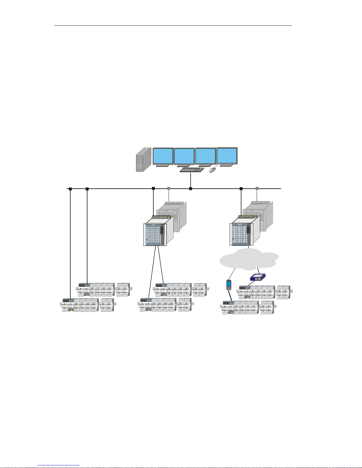
2.4.3 Configurations
Depending on master control module and protocol variant there are different communication
methods available:
· Multi-point traffic
· Dial-up traffic
─ Single-Master
─ Multi-Master
· Communication via LAN/WAN
· Communication via Intranet/GPRS
TCP/IP 60870-5-104
LAN/WAN Ethernet TCP/IP
Radio, Fibre Optics
Cable, etc...
IEC 60870-5-101
Multi-Point Traffic
Control System
Dial-up Traffic
PSTN/ISDN/GSM
IEC 60870-5-101
 Loading...