

Siemens SICAM FCM User Manual
SICAM FCM Current-Transformer Adapter, Ac cessor y
E50417-X8950-C590-A2, Edition 06.2018 Page 1
SICAM FCM Current-Transformer Adaptor
Manual
s
The current-transformer (CT) adaptor is delivered with SICAM FCM as an optional accessory and can be ordered with
separate MLFB numbers 6MD2320-0AA10-1AA0 for 1 A and 6MD2320-0AA20-1AA0 for 5 A.
The CT adaptor acts as an interface between the primary CT and SICAM FCM to convert the secondary value of 1A/5A into
a IEC 60044-8 standard conform low power signal, which is measured in SICAM FCM.
Installation Procedure s
Before installing the CT adaptor, make sure that SICAM FCM is powered-off. To install the CT adaptor with the SICAM
FCM, execute the following procedure:
1. Replace the 4 rear screws with the 4 threaded bolts in the order (diagonal to each other). Secure the 4 screws and
reuse in assembling CT adaptor to SICAM FCM.
NOTE
The maximum torque required for tightening the 4 thread bolts to SICAM FCM is 0.35 Nm.
2. Carry out the electrical connections of the 3 current inputs, 3 voltage inputs, 1 digital input, 2 digital outputs, 1 RS485
interface (Modbus RTU), 1 auxiliary power supply connection on the rear side of SICAM FCM.
3. Carry out all the necessary electrical connections of the cable assembly as per the following color coding of the wires.
Colour Coding Description
Brown Connect cores to terminal 13 (I1), 14 (I1N) of SICAM FCM
Blue Connect cores to terminal 15 (I2), 16 (I2N) of SICAM FCM
Orange Connect cores to terminal 17 (I3), 18 (I3N) of SICAM FCM
NOTE
When terminating the connector; ensure that the wires of the cable assembly are not twisted.
4. Fix the CT adaptor to SICAM FCM by using the 4 SICAM FCM screws with a maximum torque of 0.35 Nm.
5. Connect the cable assembly to the CT adaptor.
6. Before installing the primary CT wires at the CT adaptor, ensure that the primary CTs are short-circuited to avoid safety
problems.
NOTE
The 4 threaded bolts and the cable assembly are delivered with the CT adaptor.
NOTE
Always ensure the polarity when installing the primary CT cable and also follow the direction information as
mentioned on the adaptor card.
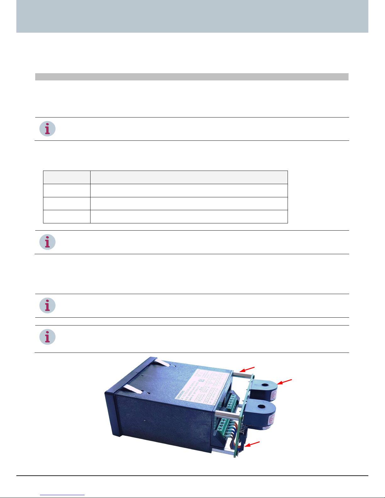
Figure 1-1 Components of the Current-Tran sformer Adaptor SICAM FCM
Cable Assembly
Threaded B olt
CT Adaptor PCB
SICAM FCM Current-Transformer Adapter, Ac cessor y
E50417-X8950-C590-A2, Edition 06.2018 Page 2
SICAM FCM Current-Transformer Adaptor
Manual
s
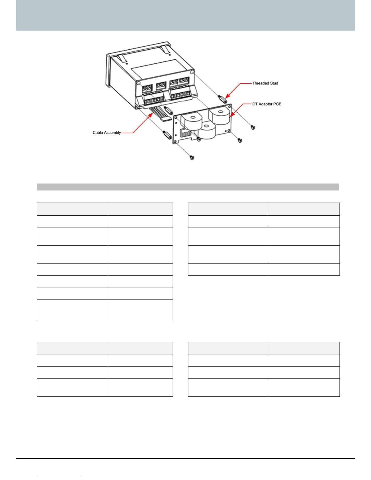
Figure 1-2 Components of the Current-Tran sformer Adaptor SICAM FCM
Technical Data g
1-1 General Characteristics 1-2 Environment
Characteristics Specifications Characteristics Specifications
Rated input current 1 A or 5 A Operating temperature range -40 °C to + 70 °C
Accuracy
1 A: ± 1 %
5 A: ± 3 %
Storage temperature range -40 °C to + 85 °C
Accuracy range
1 A: 0.4 A to 8 A
5 A: 0.4 A to 50 A
Humidity range 0 to 95 %, non-condensing
Frequency 50 Hz/60 Hz Altitude above sea level Maximum up to 2000 m
Thermal overload 100 A for 1 s
Rated output 225 mV
Consumption per phase
and ground path
≤ 0.1 VA (at ΙN = 1 A)
≤ 0.5 VA (at ΙN = 5 A)
1-3 Safety 1-4 Dimensions
Characteristics Specifications Characteristics Specifications
Dielectric as per IEC 61010-1 2.5 kV Dimensions 43 mm x 90 mm x 30 mm
Impulse as per IEC 61010-1 4 kV Weight 66 g
Vibration as per IEC 60068-26/IEC 60255-21-1
Class II Inner diameter of CT 5.8 mm
 Loading...