

Siemens SICAM CMIC User Manual

Preface
A
Open Source Software
SICAM RTUs
SICAM CMIC
User Manual
Table of Contents
Installation
Interfaces and Ci rcuitry
Preparing the Engineering
Engineering via SICAM TOOLBOX II
Engineering via SICAM WEB
Service
Variables in the Instruction List
1
2
3
4
5
6
Examples for Application Programs
Error Handling
Set Up Dial-Up Connection via PPP
Install Security Certificate
Use Cases
Glossary
B
C
D
E
F
DC8-001-2.09

Note
Disclaimer of Liability
software described, we cannot
vals and any corrections that might become necessary are included
Copyright
will be liable for damages. All rights, including rights created by
Please t ake notice of the notes and w arnings for your safety in the prefac e.
Although we have carefully checked the contents of this publication
for conformity with the hardware and
guarantee complete conformity since errors cannot be excluded.
The information provided in this manual is checked at regular inter-
in the next releases. Any suggestions for improvement are welcome.
Subject to change without prior notice.
Document Label: SICRTUS-BHBSICAMCMIC-ENG_V2.09
Release Date: 2016-08-11
Siemens AG Order no.: DC8-001-2.09
Energy Automation
Humbold ts traße 59
90459 Nürnberg
Deutschland
Copyright © Siemens AG 2016
The reproduction, transmission or use of this document or its contents is not permitted without express written authority. Offenders
patent grant or registration of a utility model or design, are reserved.

Preface
Purpose of this manual
This manual describes how to install and parameterize a SICAM CMIC system, which errors
may occur and which are the existing diagnostic options.
Particularly it contains the following information:
• Safety instructions
• Installation instructions
• Hardware descriptions (modules)
• Engineering options
• Parameterization of telecontrol applications
• Programming of open-/closed-loop control functions
• Savi ng and loading of application data
• Test functions
• Loading of firmware
• Diagnosis
Target Group
The d ocument you are reading right now is addr essed to us ers, who are in cha rge of the following engineering tasks:
• Conceptual activities, as for example design and configuration
• Mechanical installation
• C reati on of the a ssembl y tec hnical document atio n
• Engineering and testing with the designated engineering tools
• Technical system maint enance and service, module handling
Within this manual there are hints how to obtain information or files by means of the website
http://www.siemens.com/sicam. If you have no access please consult your project manager at
Siemens.
Recommendations for Third-party Products
Siemens does neither receive liability nor warranty for recommendations which are given or
implied by this manual. For the correct and intended use of the respective product the associated technical descriptions must be paid attention to in any case.
Links to Third-Party Websites
Siemens is not responsible for the contents of third-party websites mentioned in this document, as well as the correctness of the publications and links. For all product information the
respective manufacturer is respons ib le.
SICAM RTUs, User Manual SIC AM CMIC 3
DC8-001-2.09, Edition 08.2016

Preface
sometimes with
Conventions Used
• Manuals to be referred to are represented in italics, such as for instance SICAM CMIC
System Description, chapter "System Overview".
• Outputs visible on the screen are describe d in this font.
• Inputs via keyboard or mouse keys and visible on the screen are described in this
font.
• Men u po sition s vis ible on the screen are described in this font.
• Unchangeable texts that are contained in windows and are visible on the screen are
described in this font.
• Buttons in windows visible on the screen and to be operated by keyboard or mouse
are described in this font.
• Operation code from programs and variable names are described in t his font.
• Names of parameters are described in this font; they also can contain the path of
the directory tree which leads to the parameter, as for instance Parameter | CPC80 |
Topologie.
• Names of values are described in this font.
• Sym bolic names, pro gram names and f ile name extensi ons are described in this font.
Note
Within this manual describ ed functions for operation, diagnosis and test of SICAM CMIC have been
recorded by means of an industrial PC with operating system Microsoft Windows 7 Enterprise ® (Service
Pack 1) [6 4 b it] and web browser Microsoft Internet Explorer ® 10. They are vali d likewise –
inessential deviations – for other operating systems and web br owsers.
4 SICAM RTUs, User Manual SICAM CM IC
DC8-001-2.09, Edition 08.2016

Placement into the Information Landscape
Document na me Item number
SICAM CMIC System Description MC8-001-2
SICAM RTUs • SICAM I/O Modules DC8-012-2
SICAM RTUs • I/O Modules DC6-041-2
SICAM RTUs Common Functions Peripheral Elements According to
IEC 60870-5-101/104
SICAM RTUs Common Functions System and Basic System Elements DC0-015-2
SICAM RTUs • Ax 17 03 Common Functions Protocol Elements DC0-023-2
SICAM RTUs Common Functions MODBUS DC0-088-2
SICAM RTUs Common Functions DNP3 DC0-090-2
SICAM RTUs Common Functions Landis & Gyr TELEGYR 80 0 GV-S DC0-103-2
SICAM RTUs • SICAM TOOLBOX II Administrator Security Manual DC0-115-2
SICAM TOOLBOX II Online Help
CAExplus Online Help
PC Products Referenc e List D95-003-1
*)
avail able in the engineerin g s ystem SICAM TOOLBO X I I
Preface
DC0-011-2
*)
*)
Further Support
For more information, please co ntac t our Customer Support Center:
Phone: +49 (0)180 524 70 00
Fax: +49 (0)180 524 24 71
(charges depending on provider)
e-mail: support.energy@siemens.com
The Siemens Pow er Academy offers a comprehensive p rogram of prof essio nal training ev ents
in the fields of power generation, distribution and transmission.
Main training centers are:
Nuremberg, Germany (Head Office)
Phone: +49 911 433 7415
Fax: +49 911 433 5482
power-academy.ptd@siemens.com
Schenectady, NY, USA
Phone: +1 518 395 5005
Fax: +1 518 346 2777
pti-edpro.ptd@siemens.com
Vienna, Austria
Phone: +43 51707 31143
Fax: +43 51707 55243
power-academy.at@siemens.com
Hebburn, United Kingdom
Phone: +44 1914 953449
Fax: +44 1914 953693
pti-training.stdl.uk@siemens.com
SICAM RTUs, User Manual SIC AM CMIC 5
DC8-001-2.09, Edition 08.2016

Preface
Notes on Safety
This manual does not constitute a complete catalog of all safety measures required for operating the equipment (module, device) in question because special operating conditions might
require additional measures. However, it does contain notes that must be adhered to for your
own personal safety and to avoid damage to property. These notes are highlighted with a
warning triangle and different keywords indicating different degrees of danger.
Danger
means that death, serious bodily injury or considerable property dam age will occur, if the appropri ate pre-
caution ary measur es are not c arri ed out.
Warning
means that death, serious bodily injury or considerable property dam age can occur, if the appropriate pr ecaution ary measur es are not c arri ed out.
Caution
means that minor bodily injury or property damage could occu r, if the appropri ate precautionary measures
are not c arr ied out.
Note
is important inf or mation about the product, th e handli ng of the pr oduct or the respective part of the documentation, to which special attention is to be gi ven.
Qualified Personnel
Commissioning and operation of the equipment (module, device) described in this manual
must be performed by qualified personnel only. As used in the safety notes contained in this
manual, qualified personnel are those persons wh o are authorized to commission , release,
ground, and tag devices, systems, and electrical circuits in accordance with safety standards.
6 SICAM RTUs, User Manual SICAM CM IC
DC8-001-2.09, Edition 08.2016

Preface
Use as Prescribed
The equipment (device, module) must not be used for any other purposes than those described in the Catalog and the Technical Description. If it is used together with third-party devices and components, these must be recommended or approved by Siemens.
Correct and safe operation of the product requires adequate transportation, storage, installation, and mounting as well as appropriate use and maintenance.
During operation of electrical equipment, it is unavoidable that certain parts of this equipment
will carry dangerous voltages. Severe injury or damage to property can occur if the appropriate measures are not taken:
• Hazardous voltages can be present on all switching components connected to the power
supply.
• Even after the supply voltage has been disconnected, hazardous voltages can still be present in the equipment (capacitor storage).
• The limit values indicated i n the m anual or the operating instructions must not be exceeded; that also applies to testing and commissioning.
Danger
Consider obligatory the safety rules for the accomp lishment of works at electrical plants:
1. Switch off electr ic ity all-p ole and on all s ides!
2. Ensure that electricity c annot be switc hed on again!
3. Double c heck that no electrical current is flowing!
4. Discharge, ground, short circuit!
5. Cover or otherwise isolate components that are still electrically act ive!
SICAM RTUs, User Manual SIC AM CMIC 7
DC8-001-2.09, Edition 08.2016

Preface
8 SICAM RTUs, User Manual SICAM CM IC
DC8-001-2.09, Edition 08.2016

Open Source Software
This product contains, among other things, Open Source Software developed by third parties.
The Open S ourc e Software used in thi s pro duct a nd the license agreement s concerning t his
software can be fou nd in the Readme_OSS. These Open Source Softwar e f iles are p rotected
by copyright.
Your compliance with those license conditions will entitle you to use the Open Source Software as foreseen in the relevant license. In the event of conflicts between S iemens license
con ditions a nd the Open S ourc e Soft ware license conditions , the O pen Sou rce S oftw are co nditions shall prevail with respect to the Open Source Software portions of the software. The
Open Source So ftware is licen sed royalty-free.
Insofar as the applicable Open Source Software License Conditions provide for it you can order the source code of the Open Source Software from your Siemens sales contact - against
payment of the shipping and handling charges - for a period of at least 3 years since purchase
of the Product.
We are liable for this product including the Open Source Software contained in it pursuant to
the license conditions applicable to the Product. Any liability for the Open Source Software
beyond the program flow intended for this product is explicitly excluded. Furthermore any liability for defects resulting from modifications to the Open Source Software by you or third parties is excluded. We do not provide any technical support for this Product if it has been modified.
The Open S ourc e Software used in thi s pro duct a nd the license agreement s concerning t his
software can be found on the SICAM RTUs SD card in the file ReadmOSS.htm.
Path for Readme_OSS: SD card:\OSS\<Firmwarenumber>\<Revision>\ReadmOSS.htm
(e.g.: SD card:\OSS\CPC80\01.01\ReadmOSS.htm).
You need a SD card reader and a webbrowser to read the htm file.
SICAM RTUs, User Manual SIC AM CMIC 9
DC8-001-2.09, Edition 08.2016

Open Source Software Used in SICAM CMIC
10 SICAM RTUs, User Manual SIC AM CMIC
DC8-001-2.09, Edition 08.2016

Table of Contents
1 Installation ................................................................................................................... 21
1.1 Mechan ical Design ......................................................................................... 22
1.1.1 Locking Hook............................................................................................. 2 3
1.1.2 Type Plate ................................................................................................. 23
1.2 Dimens ions .................................................................................................... 2 4
1.2.1 Front View ................................................................................................. 24
1.2.2 View from the Left...................................................................................... 24
1.3 Assembly ....................................................................................................... 25
1.3.1 Installat ion Location ................................................................................... 25
1.3.2 Space Requirement ................................................................................... 25
1.3.3 Cable Duct ................................................................................................ 27
1.3.4 Installat ion Pos ition .................................................................................... 28
1.3.5 DIN Rail (TS35 Rail) .................................................................................. 28
1.3.6 Installat ion of the Device ............................................................................ 29
1.3.7 Remova l/Shi fting of the Device .................................................................. 30
1.3.8 Coupling of extern al SICAM I/O Mod ules ................................................... 31
1.3.8.1 Mounting o f the Coupl ing Mod ule for SIC AM I/O Modu l es ..................... 31
1.3.8.2 Mounting o f the Bus Conn ecto r for SIC AM I/O Mo du les ........................ 32
1.3.8.3 Mounting o f the SICAM I/O Modules ..................................................... 32
1.3.9 Coupling of Externa l SICAM TM I/O Modules ............................................. 34
1.3.10 Remove Device Coup led to I/O Modu les .................................................... 36
1.4 Installat ion of Externa l Communica tion Con nectio ns ....................................... 37
1.4.1 Serial Communica tion................................................................................ 37
1.4.1.1 Multi-Point Traffic via Leased Line Modem and VFT Channel Modem ... 37
1.4.1.2 Multi-Po int Tra ffic via Glas s Fibre Optic and Star Conn ectio n ................ 38
1.4.1.3 Dial-up Traffic Analog with Westermo TD-36 and External Supply......... 38
1.4.1.4 Dial-up Tra ffic ISDN w ith Wes te rmo ID W-90 and Exte rn a l Supply ......... 39
1.4.1.5 Dial-up Traffic GSM, SMS Sender/Re cei ver .......................................... 39
1.4.1.6 GPRS ................................................................................................... 40
1.4.2 Etherne t Communicat ion (LAN/ WAN) ........................................................ 40
1.5 Wiring Process Peripherals ............................................................................. 41
1.5.1 Periphe ral Connectors ............................................................................... 41
1.6 Shielding ........................................................................................................ 42
1.7 Protect ive Earth/ Ground ................................................................................. 43
1.8 Powe r Supply ................................................................................................. 44
1.8.1 Switching th e System On and Off .............................................................. 44
1.9 SD Card ......................................................................................................... 4 5
1.9.1 Inserting the SD Card ................................................................................ 45
1.9.2 Removin g the SD Card .............................................................................. 45
SICAM RTUs, User Manual SIC AM CMIC 11
DC8-001-2.09, Edition 08.2016

Table of Contents
2 Interface s and Circuitr y .............................................................................................. 47
2.1 Position of the Inter faces on the Hou sing ........................................................ 4 8
2.2 Pin Assignmen t .............................................................................................. 50
2.3 Block Diagra ms and Externa l Circuitry ............................................................ 52
2.3.1 Overview ................................................................................................... 52
2.3.2 Powe r Supply Module (PS-8 630) ............................................................... 52
2.3.3 Maste r Control Mod ule (CP-80 00 ) ............................................................. 53
2.3.4 Digital Inputs (DI-8100) .............................................................................. 54
2.3.5 Digital Outp uts (DO-82 03) ......................................................................... 55
2.3.5.1 1 and 2-pole Circu itry ........................................................................... 55
2.3.5.2 1½-pole Circuitry .................................................................................. 56
2.4 Cables for E xtern a l Co mmunication Con n ections............................................ 57
2.4.1 Cable for direc t RS-2 32 con n ect ion to an oth e r AU ..................................... 58
2.4.2 Modem Cable for Dial-Up Traffic (Ana log) .................................................. 59
2.4.3 Modem Cable for Dial-U p Tra ffic (ISD N) .................................................... 6 0
2.4.4 Modem Cab le for Dial-U p Traffic (GSM , SMS Sen d er/R ece i ver) ................ 61
3 Prepar ing the Engine ering .......................................................................................... 63
3.1 Enginee ring Tools .......................................................................................... 64
3.1.1 Differences ................................................................................................ 64
3.1.2 Interlocking ................................................................................................ 64
3.2 Softwa re for the Enginee ring .......................................................................... 65
3.2.1 SICAM TOOLBOX II .................................................................................. 65
3.2.1.1 Prereq uisites ........................................................................................ 66
3.2.2 SICAM WEB .............................................................................................. 67
3.2.2.1 Prereq uisites ........................................................................................ 67
3.2.2.2 Progra m WEBcmic ............................................................................... 68
3.3 Loada ble Firmwares ....................................................................................... 69
3.4 Integra ted Protocol SNMP .............................................................................. 70
3.4.1 Downloa d of the SICAM CMIC MIB-F iles ................................................... 7 0
3.4.2 Import of the MIB-Files in MIB-Brow s er ...................................................... 7 0
3.4.3 Display of SNMP-Var iab les in MIB-Brow se r ............................................... 71
3.5 SD Card ......................................................................................................... 7 3
3.5.1 SD Card Reader/ Writer .............................................................................. 73
3.6 Interface s for the Communica tion ................................................................... 74
3.7 Conne cting Eng inee r ing PC with the Ta rge t Device ........................................ 7 5
3.7.1 SICAM TOOLBOX II .................................................................................. 75
3.7.1.1 Physica l Connection ............................................................................. 75
3.7.1.1.1 Serial Point- to-P oint Conne ction ...................................................... 75
3.7.1.1.2 Serial Connection via Te leco mmun ica tion Fa cilit ies ......................... 76
3.7.1.1.3 LAN/WAN Connectio n via Ethern et Inter face ................................... 76
3.7.1.1.4 LAN/WAN Connection via Serial Interface and Terminalserver ......... 77
3.7.1.1.5 Remote Connection via further SICAM RTUs Automation Unit(s) ..... 78
3.7.2 SICAM WEB .............................................................................................. 79
12 SICAM RTUs, User Manual SIC AM CMIC
DC8-001-2.09, Edition 08.2016

Table of Contents
3.7.2.1 Physica l Conn ect ion w ith the Targ e t Device.......................................... 79
3.7.2.1.1 Point-to-Poin t Conn ect ion via Se r ial Inter face .................................. 79
3.7.2.1.2 Point-to-Poin t Conne ction via Ethern et Inter face .............................. 80
3.7.2.1.3 LAN/WAN Connectio n via Ethern et Inter face ................................... 80
3.7.2.2 Commun ication with the Target De vice ................................................. 8 1
3.7.2.2.1 Point-to-Poin t Conn ect ion via Se r ial Inter face .................................. 82
3.7.2.2.2 Point-to-Poin t Conne ction via Ethern et Inter face .............................. 83
3.7.2.2.3 LAN/WAN Connectio n via Ethern et Inter face ................................... 84
3.8 Interact ion with the Enginee ring Too l .............................................................. 88
3.8.1 SICAM TOOLBOX II .................................................................................. 88
3.8.1.1 Structure .............................................................................................. 88
3.8.2 SICAM WEB .............................................................................................. 89
3.8.2.1 Dashboard............................................................................................ 89
3.8.2.2 Genera l Butto ns ................................................................................... 9 1
3.8.2.3 Parame ter Entry ................................................................................... 93
3.8.2.3.1 Show Expert Parame ters ................................................................. 97
3.8.2.4 Resta rt Request ................................................................................... 98
3.8.2.5 SICAM TOOLBOX II Locking ................................................................ 98
3.8.2.6 Langu age Versions ............................................................................... 98
3.8.2.7 Navigation w ith the Web Bro ws er ......................................................... 99
3.8.2.8 Session Monitoring ............................................................................. 100
3.8.2.9 Exception s with Enginee ring via SICAM WEB ..................................... 1 01
4 Engineer ing via SICA M TOOLBOX I I ........................................................................ 103
4.1 Telecontro l ................................................................................................... 104
4.1.1 Presets .................................................................................................... 106
4.1.1.1 User and Rights .................................................................................. 106
4.1.1.2 Passw ord ........................................................................................... 10 7
4.1.1.3 Language ........................................................................................... 107
4.1.2 Entrance into the Projec t .......................................................................... 107
4.1.2.1 Logon ................................................................................................. 107
4.1.2.2 Logoff ................................................................................................. 107
4.1.2.3 Chang e Passw ord .............................................................................. 108
4.1.3 Plant Con figuration .................................................................................. 108
4.1.4 Import Firmware ...................................................................................... 108
4.1.5 Configu rat ion and Sett ing s for Teleco nt rol ............................................... 109
4.1.5.1 Hardw are Configuration ...................................................................... 110
4.1.5.2 System- Technica l Settings ................................................................. 1 11
4.1.5.2.1 Communication .............................................................................. 111
4.1.5.2.2 Periphery ....................................................................................... 111
4.1.5.3 Proces s-Te chnica l Setting s ................................................................ 1 12
4.1.5.3.1 Levels ............................................................................................ 112
4.1.5.3.2 Types ............................................................................................ 112
4.1.5.3.3 Images .......................................................................................... 113
SICAM RTUs, User Manual SIC AM CMIC 13
DC8-001-2.09, Edition 08.2016

Table of Contents
4.1.5.4 Decen tral Archi ving (DE AR) ............................................................... 114
4.1.6 Trans form Para meters ............................................................................. 114
4.1.7 Import, Expo rt and Backup o f Engineer ing Data ....................................... 114
4.1.8 Documen tation ........................................................................................ 114
4.1.8.1 Hardw are Configuration ...................................................................... 115
4.1.8.2 Assembly Techn ique .......................................................................... 11 5
4.1.8.3 Interface to ELCAD ............................................................................. 115
4.1.8.4 Telecontro l Function ........................................................................... 116
4.1.8.4.1 System-Techn ical Configu rat ion .................................................... 116
4.1.8.4.2 Process-Te chnical Settings ............................................................ 116
4.1.9 Commis sion ing and Test ......................................................................... 116
4.1.9.1 Loading Eng ineering Data .................................................................. 116
4.1.9.2 Parame ter Compariso n....................................................................... 117
4.1.9.3 Test Function s .................................................................................... 118
4.1.9.3.1 Status Of Spontan eou s Data Points ............................................... 1 18
4.1.9.3.2 Simulation Of Spon tan eo us Da ta Points ........................................ 119
4.1.9.3.3 Check The Conn ect ion To Automat ion Units .................................. 1 19
4.1.9.4 Display ing Decentra l Archi ve (DEAR) ................................................. 120
4.2 Automation ................................................................................................... 121
4.2.1 Creating a Function Diag ram ................................................................... 122
4.2.1.1 Restrictions with the Cre a t ion of a Function Diag ram .......................... 122
4.2.1.2 Configu ring Externa l Signals ............................................................... 1 23
4.2.1.3 Tool CAEx plus................................................................................... 123
4.2.1.4 Progra m Code Genera tion .................................................................. 1 25
4.2.2 Documen tation ........................................................................................ 126
4.2.2.1 Cross Reference List .......................................................................... 1 26
4.2.2.2 Open-/C losed-Lo op Control Function .................................................. 127
4.2.3 Commis sion ing and Test ......................................................................... 127
4.2.3.1 Loading Prog ram Code ....................................................................... 127
4.2.3.2 Test Function s .................................................................................... 128
4.2.3.2.1 Simulating Function Diag ram Offline .............................................. 1 28
4.2.3.2.2 Testing Function Diagram Online ................................................... 12 8
5 Engineer ing via SICA M WEB .................................................................................... 131
5.1 Telecontro l ................................................................................................... 132
5.1.1 Start and Termina te Ses s ion ................................................................... 133
5.1.1.1 Logon ................................................................................................. 133
5.1.1.1.1 Rights of the Users ........................................................................ 134
5.1.1.2 Logoff ................................................................................................. 135
5.1.2 Basic Settings ......................................................................................... 135
5.1.2.1 Authen tication Proce dure ................................................................... 1 36
5.1.2.1.1 Authentication via Locally Stored Creden tials ................................. 13 6
5.1.2.1.2 Authentication via Externa l Service ................................................ 137
5.1.2.2 Chang e Web Server Passwo rd ........................................................... 138
14 SICAM RTUs, User Manual SIC AM CMIC
DC8-001-2.09, Edition 08.2016

Table of Contents
5.1.2.3 Differen tiation Secure/Non-S ecure Passw ords .................................... 139
5.1.2.4 Set IP Addres ses ................................................................................ 14 2
5.1.2.4.1 Access Options for the Engineering PC in Operation ...................... 143
5.1.2.5 Autoconfiguration................................................................................ 144
5.1.3 Common Settings .................................................................................... 14 7
5.1.3.1 Configu ration of the Target Device ...................................................... 147
5.1.3.1.1 Application Progra m ...................................................................... 14 7
5.1.3.2 Topolog y ............................................................................................ 1 48
5.1.3.3 Failure Beha vior upon Fault ................................................................ 148
5.1.4 Parame terize Hardw are Con figuration ..................................................... 149
5.1.4.1 Overview ............................................................................................ 149
5.1.4.2 Protoco l Elements .............................................................................. 1 51
5.1.4.3 Periphe ral Element ............................................................................. 152
5.1.5 Configu ring Time Management ................................................................ 15 4
5.1.5.1 Time Synchroniza tion ......................................................................... 154
5.1.5.1.1 Time Synchroniza tion w ith Multi- Point T ra ffic ................................. 155
5.1.5.1.2 Time Synchroniza tion w ith Dial-u pTra ffic ........................................ 155
5.1.5.1.3 Time Synchro niza tion with Ethern et ............................................... 155
5.1.5.2 Daylight Saving Time Rule .................................................................. 156
5.1.6 Local Time Setting ................................................................................... 157
5.1.7 Configu re Communicat ion ....................................................................... 15 8
5.1.7.1 Common Settings ............................................................................... 15 8
5.1.7.2 Physica l Interface for the Commun ica tion ........................................... 159
5.1.7.3 Select Trans miss ion Facility ................................................................ 160
5.1.7.4 Setting s of the Messa ges.................................................................... 161
5.1.7.5 Data Manag emen t and Priori ty Con tro l ............................................... 162
5.1.8 Decen tral Archiving ................................................................................. 163
5.1.9 Configu re Periphe ry and Interna l Signals ................................................. 1 65
5.1.9.1 Defining Sign als ................................................................................. 1 65
5.1.9.1.1 Duplicate and Delete Rows ............................................................ 1 68
5.1.9.1.2 Automatic Filling and Auto matic Incre men tat ion ............................. 169
5.1.9.2 Assign Signals to the Master Control Element (Master Module) .......... 170
5.1.9.2.1 Configurable Log ging an d D is play o f Sign al State s ........................ 172
5.1.9.2.2 Parameters with Ass ign ment on the Maste r Contro l Modu le ........... 17 6
5.1.9.3 Assigning Signals to the Peripheral Element (I/O Master Module) ....... 182
5.1.9.3.1 Parameters w ith Assignment on the Per iph e ra l Ele men t ................ 185
5.1.9.4 Ass igning Sign a ls to the I/O Mo du le .................................................... 186
5.1.9.4.1 Automatic Display of Signa l States ................................................. 18 9
5.1.9.4.2 Parameters w ith Ass ignmen t on the DI Module .............................. 189
5.1.9.4.3 Parameters w ith Assignment on the DO Mod u le ............................ 192
5.1.9.4.4 Parameters w ith Ass ign men t on the AI Modu le .............................. 204
5.1.9.4.5 Parameters w ith As s ign men t on the A O Module............................. 209
5.1.9.5 Circuitry of Signals .............................................................................. 211
5.1.9.5.1 Binary Informa tion Acquisition ........................................................ 212
SICAM RTUs, User Manual SIC AM CMIC 15
DC8-001-2.09, Edition 08.2016

Table of Contents
5.1.9.5.2 Counting Pulse Acquis ition ............................................................ 212
5.1.9.5.3 Current/Volta ge Acquisition ............................................................ 213
5.1.9.5.4 Temperature Acquisition ................................................................ 214
5.1.9.5.5 Command Output .......................................................................... 215
5.1.9.5.6 Binary Infor mation Output .............................................................. 220
5.1.9.5.7 Current/Volta ge Output .................................................................. 220
5.1.9.6 Import and Expo r t of the Sign a l Lis t .................................................... 2 2 1
5.1.9.6.1 Export Signal List ........................................................................... 2 21
5.1.9.6.2 Import Signal List ........................................................................... 222
5.1.10 Test Function s ......................................................................................... 223
5.1.10.1.1 Suppo rted Signal Type s................................................................. 224
5.1.10.2 Display Proces s Values ...................................................................... 225
5.1.10.2.1 Suppo rte d Type Iden t ifications and Po s s ible Value s ...................... 2 2 8
5.1.10.3 Chang e Process Values ..................................................................... 229
5.1.11 Logging ................................................................................................... 233
5.1.11.1 Show Event List.................................................................................. 233
5.1.11.1.1 Export Event List ........................................................................... 235
5.1.11.2 Show Alarm List ................................................................................. 236
5.1.11.2.1 Export Alarm List ........................................................................... 238
5.2 Automation ................................................................................................... 239
5.2.1 Creating an Instru ction Lis t (IL) ................................................................ 24 0
5.2.1.1 Structure o f the Ins truct ion Lis t ........................................................... 240
5.2.1.2 Synta x for Instruction s ........................................................................ 24 1
5.2.1.2.1 General ......................................................................................... 241
5.2.1.2.2 Adressing of I/O Variables ............................................................. 2 41
5.2.1.2.3 Addressing of Flags ....................................................................... 242
5.2.1.2.4 Call of Functions ............................................................................ 242
5.2.1.2.5 Call of Function Bloc ks .................................................................. 243
5.2.1.3 Instru ction C omments ......................................................................... 243
5.2.1.4 Setting s in the Applicat ion Program .................................................... 244
5.2.1.4.1 Setting the Cycle Time ................................................................... 244
5.2.1.4.2 Spontaneous Program Execution ................................................... 245
5.2.1.5 System Informa tion............................................................................. 2 46
5.2.1.6 Command Processing According to IEC 60870-5-101/104 .................. 247
5.2.1.7 Genera tion of Inte gra ted To tals .......................................................... 247
5.2.2 Commis sion ing and Test ......................................................................... 248
5.2.2.1 Common Function s ............................................................................ 248
5.2.2.1.1 Import Application Progra m............................................................ 249
5.2.2.1.2 Load Applica tion Programm Offline ................................................ 251
5.2.2.1.3 Export Application Pro gra m ........................................................... 251
5.2.2.1.4 Syntax Check ................................................................................ 252
5.2.2.2 Test Function s .................................................................................... 252
5.2.2.2.1 Statistic Information ....................................................................... 253
5.2.2.2.2 Display Current Value o f Selecte d Variables .................................. 254
16 SICAM RTUs, User Manual SIC AM CMIC
DC8-001-2.09, Edition 08.2016

Table of Contents
5.2.2.2.3 Change Status of the App licat ion Progra m ..................................... 255
5.2.2.2.4 Change Value of Selected Variab le ................................................ 2 58
5.3 Adminis trative Functions ............................................................................... 261
5.3.1 Resta rt De vice ......................................................................................... 261
5.3.2 Saving Device Settings ............................................................................ 263
5.3.3 Reco vering Device Settings ..................................................................... 264
5.3.3.1 Loading Eng inee ring Data O ffline ....................................................... 265
5.3.4 Firmware Update ..................................................................................... 267
5.3.5 Update SICAM WEB................................................................................ 268
5.3.6 Install Languag e Package ........................................................................ 269
6 Service ....................................................................................................................... 271
6.1 Operation and Display Elements ................................................................... 272
6.1.1 LED Display ............................................................................................ 272
6.1.2 LCD Display ............................................................................................ 274
6.1.2.1 Navigation .......................................................................................... 275
6.1.2.2 Device Informat ion .............................................................................. 275
6.1.2.2.1 Device ........................................................................................... 276
6.1.2.2.2 Language ...................................................................................... 27 6
6.1.2.2.3 Display .......................................................................................... 277
6.1.2.3 Configuration ...................................................................................... 277
6.1.2.3.1 I/O Mo dules ................................................................................... 2 78
6.1.2.3.2 Protocols ....................................................................................... 279
6.1.2.3.3 Version .......................................................................................... 281
6.1.2.4 Monitor ing .......................................................................................... 2 81
6.1.2.4.1 Events | ALL Events....................................................................... 28 2
6.1.2.4.2 Events | DEF Events ...................................................................... 2 84
6.1.2.4.3 Events | DIA Events ....................................................................... 2 85
6.1.2.4.4 Alarms ........................................................................................... 286
6.1.2.4.5 Cockpit .......................................................................................... 287
6.1.2.4.6 I/O Mo dules ................................................................................... 2 88
6.2 Checks an d System Display ......................................................................... 289
6.2.1 Checks during Startup ............................................................................. 289
6.2.2 Checks after Startup ................................................................................ 29 1
6.2.3 Beha vior o f the P rocess Ou tp u ts u p o n Sta rtup and Failu re ...................... 292
6.3 Diagno sis ..................................................................................................... 29 3
6.3.1 Distinct ion of the Error Types ................................................................... 2 93
6.3.2 SICAM TOOLBOX II ................................................................................ 294
6.3.2.1 Conne ction Possibilit ies for the Diagnosis ........................................... 2 94
6.3.2.2 System Diagnosis ............................................................................... 296
6.3.2.3 System Performance .......................................................................... 298
6.3.2.4 Diagno sis of the Open-/Clos e d-Lo op Contro l Function ........................ 298
6.3.3 SICAM WEB ............................................................................................ 300
6.3.3.1 Conne ction Possibilit ies for the Diagnosis ........................................... 3 00
SICAM RTUs, User Manual SIC AM CMIC 17
DC8-001-2.09, Edition 08.2016

Table of Contents
6.3.3.2 System Diagnosis ............................................................................... 301
6.3.3.2.1 Device ........................................................................................... 302
6.3.3.2.2 Diagnosis ...................................................................................... 30 3
6.3.3.2.3 History ........................................................................................... 305
6.3.3.2.4 Export History ................................................................................ 30 7
6.3.3.3 Diagno sis of the Time ......................................................................... 308
6.3.3.4 Diagno sis of the Open-/Clos e d-Lo op Contro l Function ........................ 308
6.4 Maintena nce of the Hardw are ....................................................................... 309
6.4.1 Recog nition of Hardware Errors ............................................................... 309
6.4.1.1 Interna l Mod ules ................................................................................. 309
6.4.1.2 SD Card ............................................................................................. 309
6.4.2 Replace ment of a System ........................................................................ 310
6.4.3 Adapt new Me ch an ica l Con figura t ion in the Pa rameteri za tion .................. 3 11
6.4.3.1 Adding I/O Modules ............................................................................ 3 11
6.4.4 Replace men t of the SD Card ................................................................... 311
6.4.4.1 Initializa t ion of the Firmware ............................................................... 311
6.5 Firmware Update .......................................................................................... 312
6.5.1 SICAM TOOLBOX II ................................................................................ 312
6.5.1.1 Interrog ation of the Firmw are Revision ................................................ 312
6.5.1.2 Import ing Mas te r Data into the S IC AM T OOLB OX II ........................... 313
6.5.1.3 Loading Fir mwa re Code s into the Target Device ................................. 313
6.5.1.3.1 Loading Firmware Online ............................................................... 3 13
6.5.1.3.2 Loading Firmware Offline ............................................................... 3 14
6.5.2 SICAM WEB ............................................................................................ 314
6.5.2.1 Loading Fir mwa re Code s into the Target Device ................................. 314
6.5.2.1.1 Loading Firmware Online ............................................................... 3 14
6.5.2.1.2 Loading Firmware Offline ............................................................... 3 15
6.5.3 Errors w ith Loading o f Firmw are .............................................................. 3 15
6.6 Remote Mainte nance ................................................................................... 316
6.6.1 Configu rat ion o f Ser ver and C lien ts ......................................................... 316
A Variable s in the Instr uc ti on Lis t ............................................................................... 317
A.1 Systemvariables ........................................................................................... 318
A.1.1 System Errors ......................................................................................... 318
A.1.2 Genera l Var iables .................................................................................... 31 9
A.2 Datapo ints of the Periphera l Element ............................................................ 3 20
B Example s for Applica tio n Progra ms ........................................................................ 321
B.1 Transfer an Input to a Signalling Output and to a Command Output .............. 322
B.2 Combine tw o Inputs w ith AND ...................................................................... 32 3
B.3 Linear Adapta tion with Value Se lect ion ......................................................... 324
B.4 Operating Hours Counter .............................................................................. 325
B.5 Bounce Suppre ssion .................................................................................... 327
B.6 Setpoint Command ....................................................................................... 32 9
18 SICAM RTUs, User Manual SIC AM CMIC
DC8-001-2.09, Edition 08.2016

Table of Contents
B.7 Speed Compar ison ....................................................................................... 330
C Error Handli ng ........................................................................................................... 331
C.1 Erro rs with the Engineer ing via S IC AM WEB ................................................ 332
D Set Up Dial-U p Con ne ction via PPP ......................................................................... 335
D.1 Se ttings under Microso ft Windows ................................................................ 336
D.2 Se tting s in Microso ft Window s 8 ................................................................... 337
D.2.1 Mo dem Installat ion .................................................................................. 337
D.2.2 N etwork Configurat ion ............................................................................. 34 0
D.3 Se tting s in Microso ft Window s 7 ................................................................... 348
D.3.1 Mo dem Installat ion .................................................................................. 348
D.3.2 N etwork Configurat ion ............................................................................. 35 0
D.4 Se tting s in Micros o ft Windo ws Vis ta ............................................................. 358
D.4.1 Mo dem Installat ion .................................................................................. 358
D.4.2 N etwork Configurat ion ............................................................................. 36 0
D.5 Se tt ings in Micro s o ft Wind ow s X P Profes s iona l ............................................ 368
D.5.1 Mo dem Installat ion .................................................................................. 368
D.5.2 N etwork Configurat ion ............................................................................. 37 0
D.6 Se tting s in Micro so ft Wind ow s 20 00 Profes s ion al ......................................... 377
D.6.1 Mo dem Installat ion .................................................................................. 377
D.6.2 C onfigu rat ion of Network and Dial-Up Conn ection s .................................. 38 0
D.7 Re s tore Settings for the Intern et Us e ............................................................ 385
E Install Security Certif icate ......................................................................................... 387
E.1 General ........................................................................................................ 388
E.2 Certifica te Warning w ith MS Wind ow s XP ® ................................................. 389
E.3 Certifica te Warn ing with MS Windo ws 7 ® (64Bit) ......................................... 391
F Use Cases .................................................................................................................. 395
F.1 SICAM CMIC as Telecontrol Substat ion ....................................................... 396
F.2 SICAM CMIC as Telecont rol Substation with Node Function (Protocol
Converter) .................................................................................................... 397
F.3 SICAM CMIC as Telecontrol Substation with Integrated Switch for External
System Conne ction ...................................................................................... 3 98
F.4 SICAM CMIC as Telecontrol Substation with Integrated Switch for SICAM
TOOLBOX II Connect ion .............................................................................. 399
F.5 SICAM CMIC wi th IPSec VPN ...................................................................... 40 0
F.5.1 SICAM CMIC as Telecontrol Substation with IPSec VPN via fixed
Network ................................................................................................... 401
F.5.2 SICAM CMIC as Telecontrol Substation with IPSec VPN via GPRS
Router and ADSL Network ....................................................................... 402
F.5.3 SICAM CMIC as Telecontrol Substation with IPSec VPN via GPRS
Network ................................................................................................... 403
SICAM RTUs, User Manual SIC AM CMIC 19
DC8-001-2.09, Edition 08.2016

Table of Contents
Glossa ry .............................................................................................................................. 405
20 SICAM RTUs, User Manual SIC AM CMIC
DC8-001-2.09, Edition 08.2016

1 Installation
Contents
1.1 Mechan ical Design ......................................................................................... 22
1.2 Dimens ions .................................................................................................... 2 4
1.3 Assembly ....................................................................................................... 25
1.4 Installat ion of Externa l Communica tion Con nectio ns ....................................... 37
1.5 Wiring Process Peripherals ............................................................................. 41
1.6 Shielding ........................................................................................................ 42
1.7 Protect ive Earth/ Ground ................................................................................. 43
1.8 Powe r Supply ................................................................................................. 44
1.9 SD Card ......................................................................................................... 4 5
This chapter describes the structure of the system SICAM CMIC, how and where it may be installed, and how the wirings are to be accomplished.
SICAM RTUs, User Manual SIC AM CMIC 21
DC8-001-2.09, Edition 08.2016
Installation
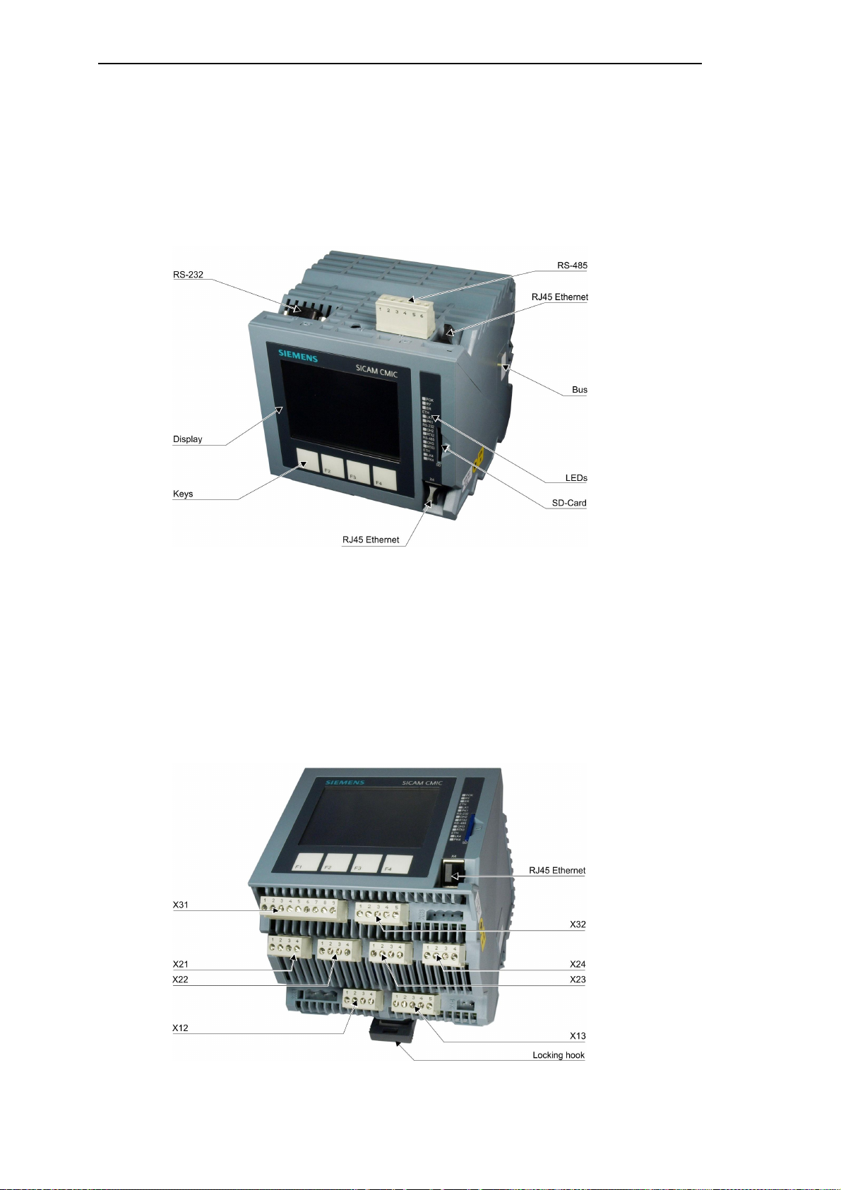
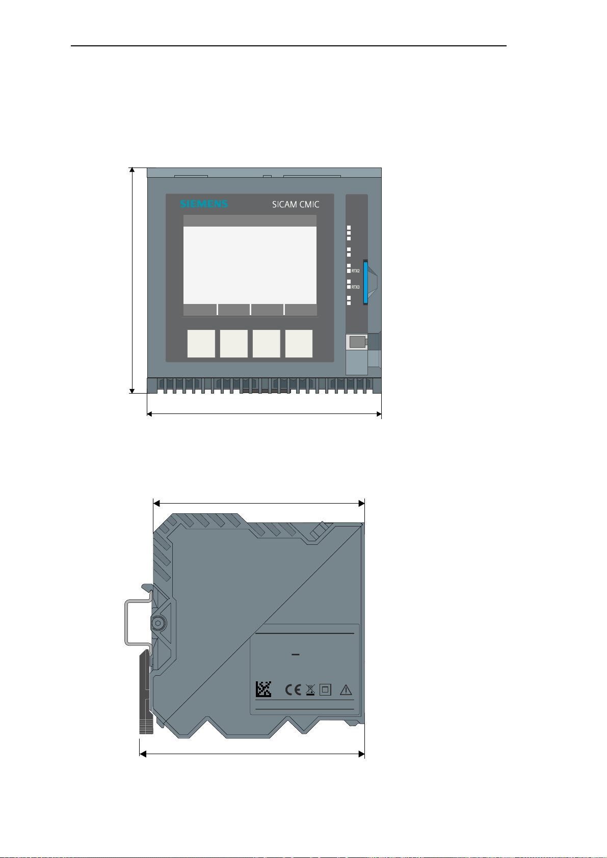
1.1 Mechanical Design
The elect rical components of the device are housed in a plastic casin g with the dimension s
128 mm x 124 mm x 116 mm (W x H x D). The casing is designed for assembly on a DIN rail.
At the front are the operation and display elements, an interface for the communication via
Ethernet, and a slot for the SD card.
At the top of the device are the connections for the communication via RS-485 and RS-232,
as well as a further Ethernet interface.
On the right side of the housing is the BUS-connector for the SICAM TM I/O coupling module.
It is covered with a label.
On the bottom side of the device are the connections for the process signals as well as for the
supply voltage.
22 SICAM RTUs, User Manual SIC AM CMIC
DC8-001-2.09, Edition 08.2016
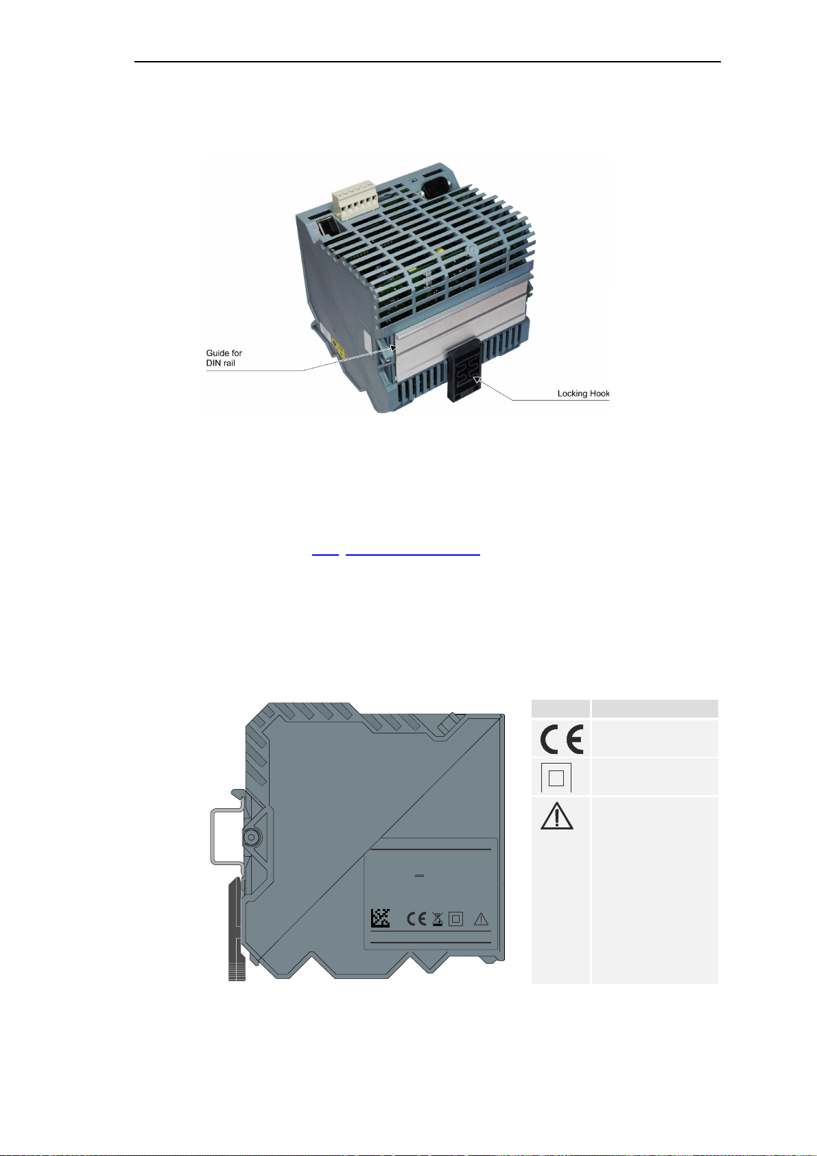
At the back is the DIN rail mounting.
U
SIEMENS
SICAM CMIC
= 18 V - 70 V
Made in Germany
www.siemens.com/sicam
Installation
1.1.1 Locking Hook
The device is locked onto the DIN rail and also removed again using the locking hook.
Details see section1.3.6, Installation of the Device.
1.1.2 Type Plate
On the left side of the housing resides the type plate with specific information as power consumption, or der number, serial n umber, har dware a ddr ess for the networ k operation (MA C
address).
Input:
= 1,2 A - 0,6 A
I
max
00-00-00-00-00-00
BF0000000000
Symbol Bedeutung
CE conformity
Protection class II /
protecti ve i ns ulation
The documentation
must be observed
6MF21010AB100AA0DE
SICAM RTUs, User Manual SIC AM CMIC 23
DC8-001-2.09, Edition 08.2016
Installation
124mm
128 mm
POK
ETH
LK1
PK1
RS-232
RS-485
ETH
LK4
PK4
123 mm
116 mm
U
SIEMENS
SICAM CMIC
= 18 V - 70 V
Made in Germany
www.siemens.com/sicam
1.2 Dimensions
1.2.1 Front View
RY
ER
OH2
OH3
SD
X4
1.2.2 View from the Left
Input:
= 1,2 A - 0,6 A
I
max
00-00-00-00-00-00
BF0000000000
F4F3F2F1
6MF21010AB100AA0DE
24 SICAM RTUs, User Manual SIC AM CMIC
DC8-001-2.09, Edition 08.2016
1.3 Assembly
128
30
124min.30*)
**)
30
1.3.1 Installation Location
The terminal modules are designed for the installation in a cabinet, rack or on the wall.
For details on the subject of environmental conditions, please refer to the SICAM CMIC Sys-
tem Description, chapter “Technical Data System”, section "Ambient Conditions".
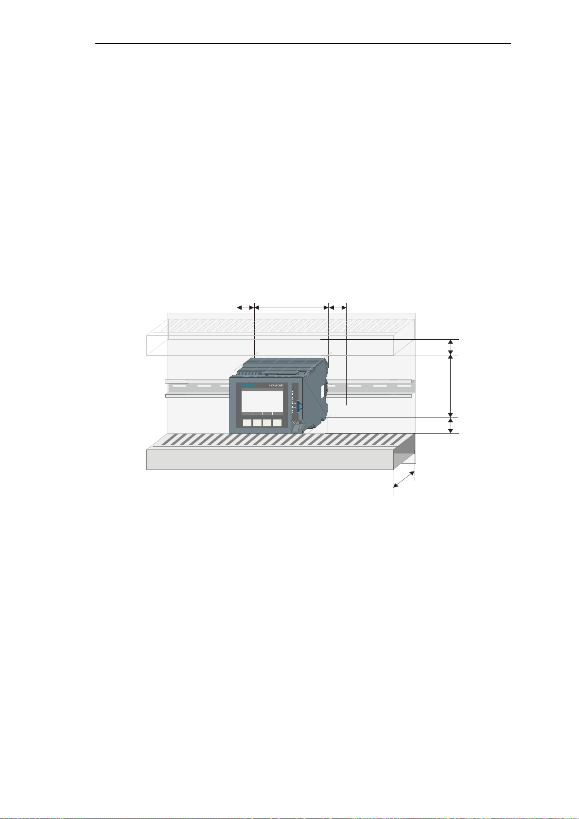
1.3.2 Space Requirement
Besides the size of the device (124 mm) the space requirement for the height is dependent on
the size of the cable ducts used and their minimum distance to the device.
Installation
30
POK
RY
ER
ETH
LK1
PK1
RS-232
OH2
RS-485
OH3
ETH
LK4
PK4
SD
X4
F4F3F2F1
*)
F or thermal reasons, a minimu m distance of 30 mm must be maintain ed around the device.
When using a cabl e duct with 1 00 mm dept h ** ) below t he device, it i s necessary to keep a 50
mm mini mum distance between device and cable duct to operat e the locking hook.
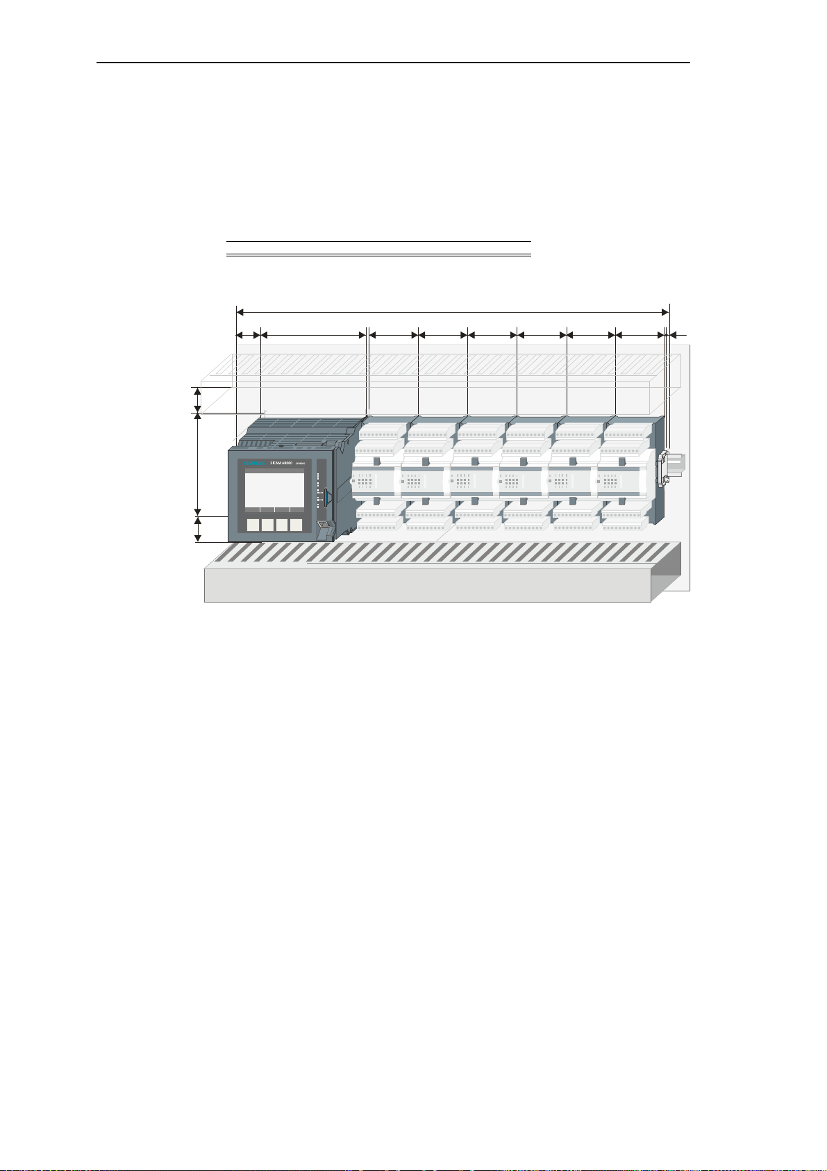
If the device is extended by external I/O modules (SICAM TM I/O modules or
SICAM I/O modules, max. 6 are permitted), then you must consider the width of the coupling
module, the I/O modules, the bus protection cap and the end clamp/grounding terminal. See
the foll owing examples :
SICAM RTUs, User Manual SIC AM CMIC 25
DC8-001-2.09, Edition 08.2016
Installation
min
.
636363
549536363
Example: SICAM CMIC + 6 ext. SICAM TM I/O Modules
Ther mical space ...................................................... 30
SICAM CM IC hous ing ........................................... 128
SICAM T M coup ling modu le ......................................5
SICAM TM I/ O modules (6 x 63) ............................ 378
(63 mm for each module; max. 6 possible)
Prote ctive ca p for bus ................................................3
End clamp .................................................................5
Horiz ont al spa ce re quirement (m m) ....................... 549
12830
5
63
30
124
POK
RY
ER
ETH
LK1
PK1
RS-232
OH2
RS-485
OH3
ETH
LK4
PK4
SD
X4
F4F3F2F1
30 *)
26 SICAM RTUs, User Manual SIC AM CMIC
DC8-001-2.09, Edition 08.2016
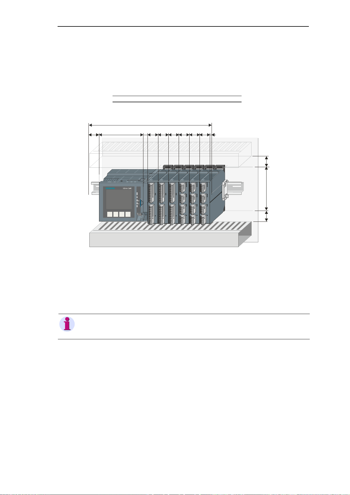
Example: SICAM CMIC + 6 ext. SICAM I/O modules
min.30124
355,5
303030
m
in.30
Ther mica l space ..................................................... 30
SICAM CMIC hous ing ............................................128
SICAM CMIC coup ling module .............................. 12,5
SICAM I/O modules (6 x 30) ..................................180
(30 mm for each module; max. 6 permitted)
End clamp ................................................................ 5
Horiz ont al spa ce requ ire me nt (m m)..................... 355,5
Installation
30
128
1.3.3 Cable Duct
Cable ducts are recommended for the cabling above and below the device. The minimum distance from the device to the cable duct is 30 mm.
12,5
30
POK
RY
ER
ETH
LK1
PK1
RS-232
OH2
RS-485
OH3
ETH
LK4
PK4
SD
X4
F4F3F2F1
530 30
Note
When using a cable duct with 1 00 mm depth below the device, i t is necess ary to keep a 50 mm minim um
distance between device and cable duct to oper ate the loc king hook.
SICAM RTUs, User Manual SIC AM CMIC 27
DC8-001-2.09, Edition 08.2016
Installation
F4F
3F2
F
1
POKRYERETHLK1PK1RS-
232OH2RS-
485OH3ETHLK4PK4SD
X
4
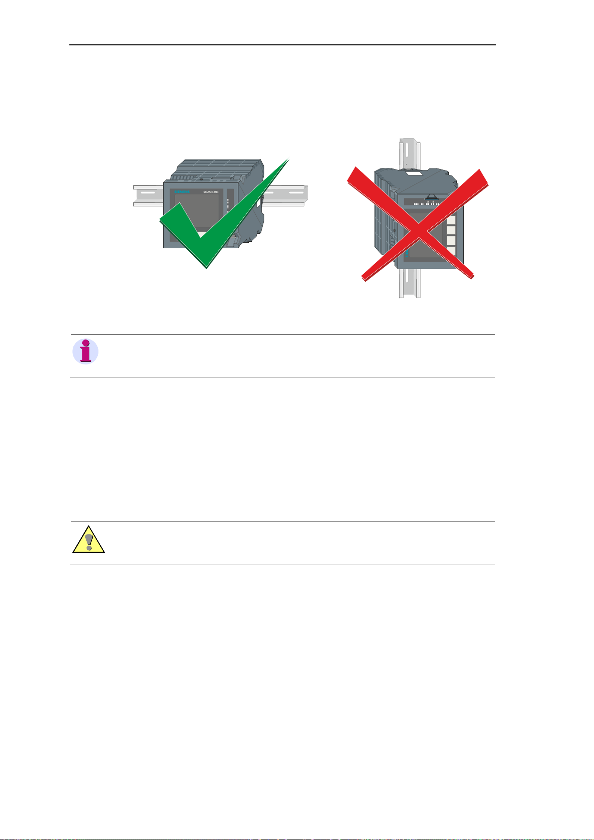
1.3.4 Installation Position
SICAM CMIC may only be installed horizontally.
F4
F3F2F1
horizon t al m ounting posi ti on vertic al m ount ing positi on
POK
RY
ER
ETH
LK1
PK1
RS-2 32
OH2
RS-4 85
OH3
ETH
LK4
PK4
SD
X4
Note
Not permitted is th e vertic al install ation or installations on th e ceiling and on the f loor (exc essive temperature, dust load).
1.3.5 DIN Rail (TS35 Rail)
For the installation of SICAM CMIC a DIN rail is to be used, which conforms to the European
Standard EN 50 022. The orientation and position in which the DIN rail is to be installed must
be determined locally.
The DIN rail must be installed horizontally on a vertical wall.
Warning
The conn ection of th e DIN rail with the cabinet/rack must guaran tee a reliable grounding of SICAM CMIC.
The cabinet/rack itself must be grounded properly.
28 SICAM RTUs, User Manual SIC AM CMIC
DC8-001-2.09, Edition 08.2016
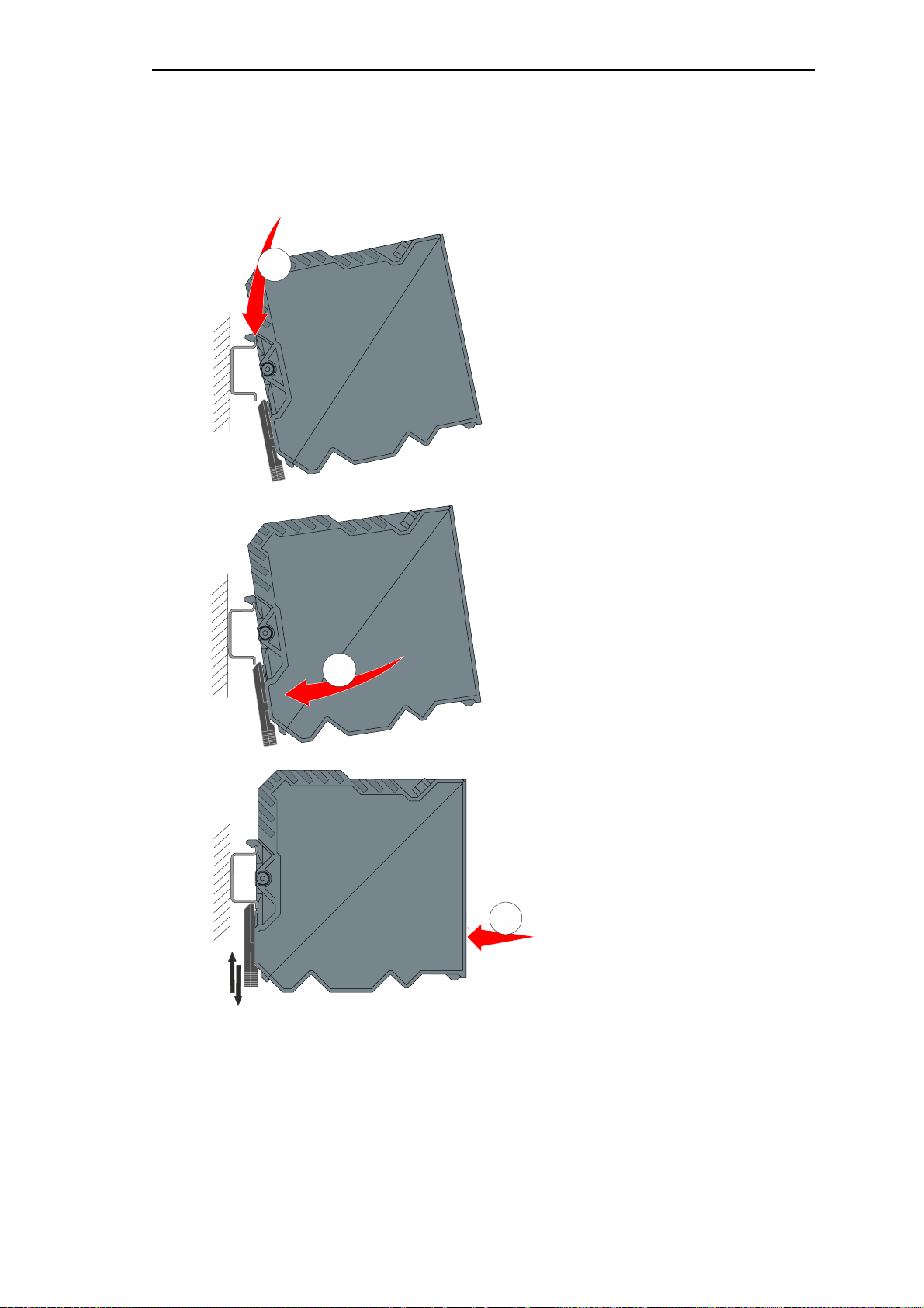
1.3.6 Installation of the Device
3
SICAM CMIC can be installed on the DIN rail by hand, without any tools.
1
Installation
Hang the inclined device in the top
edge of the DIN rail.
2
Swing the device until the locking
hook has contact with the bottom
edge of the DIN rail.
Push the casing to the back. As a
result the locking hook opens
briefly and the casing engages in
the rail .
SICAM RTUs, User Manual SIC AM CMIC 29
DC8-001-2.09, Edition 08.2016
Installation
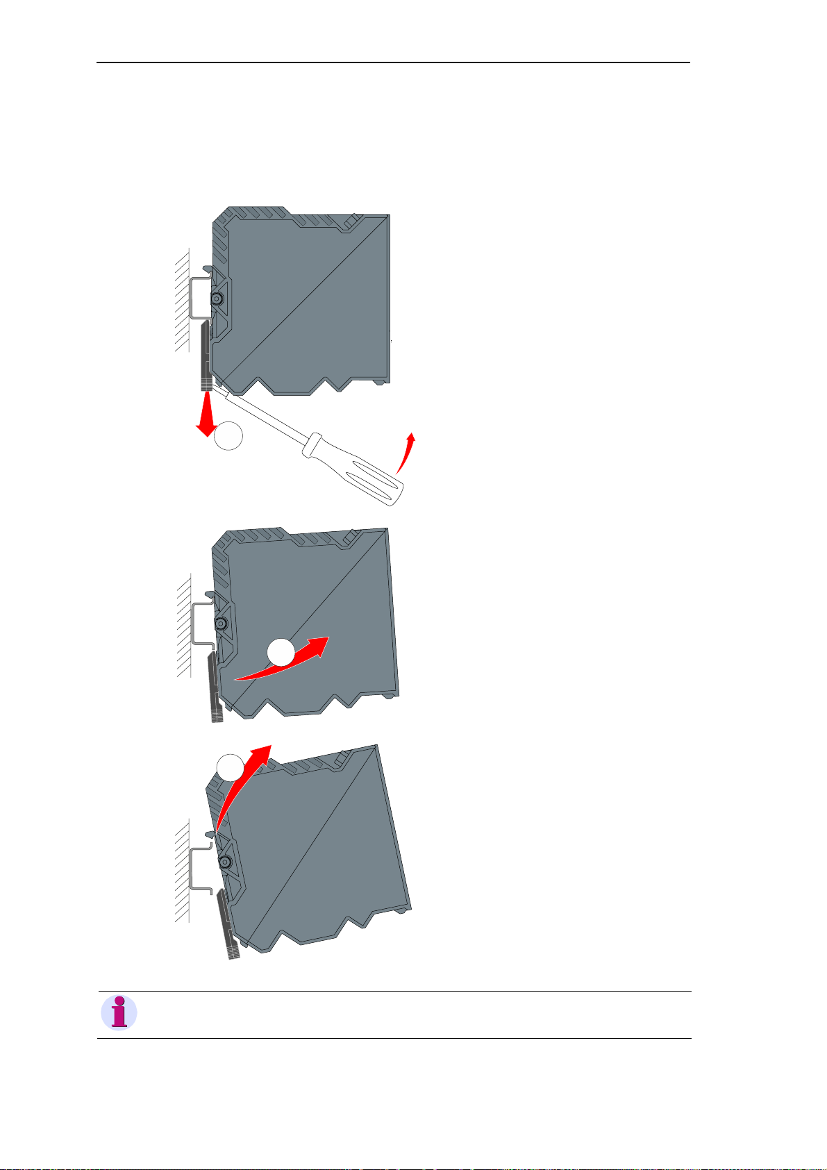
1.3.7 Removal/Shifting of the Device
To remove the device again, or to change its position on the DIN rail, the locking hook must
be opened again.
1
Insert a screwdriver suitable for
slotted screws into the locking
hook below the casing. The screw
driver must have contact to the
housing.
The locking hook is opened by
carefully pushing the screwdriver
upwards.
Swing the bottom section of the
device slightly forward.
2
Lift the device upwards out of the
3
rail.
Note
If external TM I/O modules are cou pled to your device, then you can only r emove the device af ter separating the external I/O modules from the SICAM CMIC device.
30 SICAM RTUs, User Manual SIC AM CMIC
DC8-001-2.09, Edition 08.2016
 Loading...