

Page 1

SICAM RTUs
SICAM AK
Redundan
Preface
Redundancy via SCA
1
Redundancy via CP
2
SICAM RTUs AK3: Redundancy in one
Rack
3
Configuration of SICAM AK
A
cy
, Table of Contents
-RS
-6010
and CP-6010
Unrestricted DC2-026-2.07
Page 2

Note
Please take notice of the notes and warnings for your safety in the preface.
Disclaimer of Liability
Although we have carefully checked the contents of this publication
for conformity with the hardware and software described, we cannot
guarantee complete conformity since errors cannot be excluded.
The
intervals and any corrections that might become necessary are
included in the next releases. Any suggestions for improvement are
welcome.
Subject to change without prior notice.
Document Label:
Release Date:
Copyright
Copyright © Siemens AG
The reproduction, trans m iss io n or use of t his doc um e nt or its
contents is not permitte d wi
Offenders will be liable for damages. All rights, including rights
created by patent grant or regi str ati o n o f a utility model or design,
are reserved.
information provided in this manual is checked at regular
SICRTUs-HBSICAMAKRED-ENG_V2.07
10.2016
Siemens AG Unrestricted Order no.: DC2-026-2.07
2016
thout express written authority.
Page 3

Preface
Purpose of this manual
This manual describes basic terms about redundancy in SICAM AK and conveys basic
knowledge about the principle functionality of redundancy:
• Redundant basic system elements (BSE)
• Redundant automation units (AU)
under the aspects of redundancy switchover, hardware redundancy and application-related
redundancy.
In addition certain default confi gurati ons are show n:
• Representation of the configurations
• Connection instructions
• Information about cable types and lengths use d
• List of modules and cables used
• Parameterization of the redundancy application
Target Group
The document you are reading right now is addressed to users, who are in charge of the
following engineering tasks:
• Conceptual activities, as for example design and configuration
• Mechanical installation
• Engineering and testing with the designated engineering tools
• Technical system maintenanc e and servi ce, mod ule han dlin g
Within this manual there are hints how to obtain information or files by means of
Support Products. If you have no access please consult your project manager at Siemens.
Online
SICAM RTUs, SICAM AK Redundancy Unrestricted
DC2-026-2.07, Edition 10.2016
3
Page 4

Preface
Placement into the Information Landscape
Document name Item number
SICAM AK System Description MC2-021-2
SICAM AK user Manual DC2-017-2
SICAM RTUs Common Functions Peripheral Elements According to
IEC 60870-5-101/104
SICAM RTUs Common Functions System and Basic System Elements DC0-015-2
SICAM RTUs Common Functions Protocol Elements DC0-023-2
SICAM TOOLBOX II Online Help *)
CAEx plus Online Help *)
*)
available in the engineering system SICAM TOOLBOX II
Further Support
For more information, please contact our C ust omer Suppor t Cent er:
Phone: +49 (0)180 524 70 00
Fax: +49 (0)180 524 24 71
(charges depending on provider)
support.ic@siemens.com
e-mail:
DC0-011-2
The
Siemens Power Academy offers a comprehensive program of professional training events
in the fields of power generation, distribution and transmission.
Main training centers are:
Nuremberg, Germany (Head Office)
Phone: +49 911 433 7415
Fax: +49 911 433 5482
power-academy.ptd@siemens.com
Schenectady, NY, USA
Phone: +1 518 395 5005
Fax: +1 518 346 2777
pti-edpro.ptd@siemens.com
Vienna, Austria
Phone: +43 51707 31143
Fax: +43 51707 55243
power-academy.at@siemens.com
Hebburn, United Kingdom
Phone: +44 1914 953449
Fax: +44 1914 953693
pti-training.stdl.uk@siemens.com
4 Unrestricted SICAM RTUs, SICAM AK Redundancy
Edition 10.2016, DC2-026-2.07
Page 5

Qualified Personnel
Danger
Consider obligatory the safety r
1. Switch off electricity all
2. Ensure that electricity cannot be switched on again!
3. Double check that no electrical current is flowing!
4. Discharge, ground, short circu
5. Cover or otherwise isolate components that are still electrically active!
Commissioning and operation of the equipm ent (mo dule, device) described in this manual
must be performed by qualified personnel only. As used in the safety notes contained in this
manual, qualified personnel are those persons who are authorized to commission, release,
ground, and tag devices, systems, and electrical circuits in accordance with safety standards.
Use as Prescribed
The equipment (device, module) must not be used for any other purposes than those
described in the Catalog and the Technical Description. If it is used together with third-party
devices and components, these must be recommended or approved by Siemens.
Correct and safe operation of the product requires adequate transportation, storage,
installation, and mounting as well as appropriate use and maintenance.
During operation of electrical equipment, it is unavoidable that certain parts of this equipment
will carry dangerous voltages. Severe injury or damage to property can occur if the
appropriate measures are not taken:
Preface
• Hazardous voltages can be present on all switching co mpon ents con ne cted to the pow er
supply.
• Even after the supply voltage has been disconnected, hazardous voltages can still be
present in the equipment (capacitor storage).
• The limit values indicated in the manual or the operating instructions must not be
exceeded; that also applies to testing and commissioning.
ules for the accomplishment of works at electrical plants:
-pole and on all sides!
it!
SICAM RTUs, SICAM AK Redundancy Unrestricted 5
DC2-026-2.07, Edition 10.2016
Page 6

Preface
6 Unrestricted SICAM RTUs, SICAM AK Redundancy
Edition 10.2016, DC2-026-2.07
Page 7

Open Source Software
This product contains, among other things, Open Source Software developed by third parties.
The Open Source Software used in this product and the license agreements concerning this
software can be found in the Readme_OSS. These Open Source Software files are protected
by copyright.
Your compliance with those license conditions will entitle you to use the Open Source
Software as foreseen in the relevant license. In the event of conflicts between Siemens
license conditions and the Open Source Software license conditions, the Open Source
Software conditions shall prevail with respect to the Open Source Software portions of the
software. The Open Source Software is licensed royalty-free.
Insofar as the applicable Open Source Software License Conditions provide for it you can
order the source code of the Open Source Software from your Siemens sales contact against payment of the shipping and handli ng charg es - for a period of at least 3 years since
purchase of the Product.
We are liable for this product including the Open Source Software contained in it pursuant to
the license conditions applicable to the Product. Any liability for the Open Source Software
beyond the program flow intended for this product is explicitly excluded. Furthermore any
liability for defects resulting from modifications to the Open Source Software by you or third
parties is excluded. We do not provide any technical support for this Product if it has been
modified.
SICAM RTUs, SICAM AK Redundancy Unrestricted
DC2-026-2.07, Edition 10.2016
7
Page 8

Open Source Software
8 Unrestricted SICAM RTUs, SICAM AK Redundancy
Edition 10.2016, DC2-026-2.07
Page 9

Table of Contents
1 Redundancy via SCA-RS .................................................................................................13
1.1 Overview .............................................................................................................14
1.1.1 Redundancy ..................................................................................................14
1.1.2 Synchronization .............................................................................................15
1.1.2.1 CAEx plus Program ..................................................................................17
1.1.2.2 Singular Ax PE .........................................................................................17
1.1.3 Voting ............................................................................................................19
1.1.3.1 Automatic Voting ......................................................................................19
1.1.3.2 Application-Related Voting .......................................................................19
1.1.4 Redundancy Switchover ................................................................................19
1.1.5 Overview of Redundancy Modes ..................................................................20
1.1.6 Overview of Synchronization Modes .............................................................21
1.2 CPU-Redundancy (Redundant Basic System Elements) ..................................23
1.2.1 Default Configurations ...................................................................................24
1.2.1.1 SICAM AK - SICAM AK PE, electrically connected .................................24
1.2.1.2 SICAM AK - SICAM TM PE, Electrically Connected ................................26
1.2.1.3 SICAM AK - SICAM TM PE, Electrically and Optically Connected ..........28
1.2.1.4 SICAM AK - SICAM TM PE, Optical, Red. BSE + Red . Ax -PE-Bus ........30
1.2.2 Data Transfer Between Redundant BSE Pairs ............................................31
1.2.3 Parameter Setting..........................................................................................32
1.2.3.1 Parameter Setting of the CP-2014/CPCX25 ............................................32
1.2.3.2 Automatic Voting ......................................................................................34
1.2.3.3 Settings for PREs (CPU Redundancy) .....................................................35
1.2.3.4 Settings for BSEs (CPU Redundancy) .....................................................38
1.3 Redundant Automation Units..............................................................................41
1.3.1 Default Configurations ...................................................................................42
1.3.1.1 Redundant AUs, Voting by SCA-RS, Distance up to 15 m .....................42
1.3.1.2 Redundant AUs, Voting by SCA-RS, Distance up to 200 m ....................45
1.3.1.3 Redundant AUs, Voting by SCA-RS, Distance higher than 200 m ..........47
1.3.1.4 Redundant Automation Units in Star-Shaped Configurations ..................45
1.3.1.5 Redundant Automation Units in Ring-Shaped Configurations .................51
1.3.2 Parameter Setting..........................................................................................52
1.3.2.1 Parameter Setting of the CP-2014/CPCX25 ............................................52
1.3.2.2 Settings for PREs (AU Redundancy) .......................................................53
1.3.2.3 Settings for BSEs (AU Redundancy) .......................................................55
1.4 Parameter Setting of the CP-2017/PCCX25 ......................................................58
1.4.1 Mirror Parameters ..........................................................................................61
1.5 Redundancy of Power Supply ............................................................................63
1.5.1 General ..........................................................................................................63
1.5.2 Possible Configurations .................................................................................64
SICAM RTUs, SICAM AK Redundancy Unrestricted
DC2-026-2.07, Edition 10.2016
9
Page 10

Table of Contents
1.5.2.1 Fitting Power Supply in CM-2834 .............................................................65
1.5.2.1.1 Installing 1st Power Supply ..................................................................65
1.5.2.1.2 Installing 2nd Power Supply .................................................................65
1.5.2.2 Fitting Power Supply in CM-2836 .............................................................67
1.5.2.2.1 Installing 1st Power Supply ..................................................................67
1.5.2.2.2 Installing 2nd Power Supply .................................................................67
1.5.2.2.3 Installing the 3rd and 4th Power Supply ................................................69
1.5.2.3 Fitting Power Supply in CM-2833 .............................................................72
1.5.2.3.1 Installing 1st Power Supply ..................................................................72
1.5.2.3.2 Installing 2nd Power Supply .................................................................73
1.5.2.4 Parameter Setting ....................................................................................75
1.6 Redundancy Messages ......................................................................................76
1.6.1 Redundancy Control Messages ....................................................................76
1.6.2 Redundancy Return Information Messages ..................................................81
1.6.3 Redundancy Control with CAEx plus ............................................................83
2 Redundancy via CP-6010 ................................................................................................85
2.1 Overview .............................................................................................................86
2.1.1 System Components .....................................................................................86
2.1.2 Function .........................................................................................................87
2.2 CP-6010 (Redundancy Voter) ............................................................................88
2.2.1 Power Supply and Firmware .........................................................................88
2.2.2 Lighted Display ..............................................................................................89
2.2.2.1 Behavior ...................................................................................................90
2.2.3 CM-6820 (Key Switch Module) ......................................................................91
2.2.4 SICAM AK Redundanc y without Key Switch .................................................92
2.3 Connecting SICAM AK Redundancy System .....................................................93
2.3.1 Configuration .................................................................................................93
2.3.2 Necessary Components ................................................................................94
2.3.3 Connector Pin Assignment ............................................................................95
2.3.4 Configuration Switch......................................................................................95
2.4 SICAM AK Redundanc y Engineering .................................................................96
2.4.1 Initializing Target System ..............................................................................96
2.4.1.1 Configure IP Address for Engineering PC ................................................96
2.4.1.2 Loading Firmware .....................................................................................97
2.4.1.3 SD Card Error ...........................................................................................97
2.4.2 Parameterization ...........................................................................................98
2.4.2.1 Logon........................................................................................................98
2.4.2.2 User and Rights ......................................................................................100
2.4.2.3 Set Addresses ........................................................................................100
2.4.2.3.1 IP Configuration ................................................................................100
2.4.2.3.2 Address configuration acc ording to IEC 60870-5-104 ......................101
2.4.2.3.3 Reload Default Parameters ...............................................................103
2.4.2.3.4 Load Updated Firmware ....................................................................103
10 Unrestricted SICAM RTUs, SICAM AK Redundancy
Edition 10.2016, DC2-026-2.07
Page 11

Table of Contents
2.4.3 Time Settings ...............................................................................................103
2.4.3.1 Local Time Set .......................................................................................103
2.4.3.2 Time Zone ..............................................................................................104
2.4.3.3 Daylight Saving Time Rule .....................................................................105
2.4.4 Data Recording ............................................................................................105
2.4.4.1 Event Log ...............................................................................................105
2.4.4.2 Diagnostics Log ......................................................................................106
2.5 SICAM AK Switchover Sett i ngs ........................................................................107
2.5.1 Communication Settings .............................................................................107
2.5.1.1 System-Technical Settings .....................................................................107
2.5.2 Example of Global Switchover ....................................................................109
2.5.2.1 System-Technical Settings .....................................................................109
2.5.2.2 Process-Technical Settings ....................................................................110
2.5.2.2.1 Control Message from CP-6010 to SICAM AK .................................111
2.5.2.2.2 Return Information Message from SICAM AK to CP-6010 ...............112
2.5.3 Example of Line-by-Line Switchover ...........................................................113
2.5.3.1 System-Technical Settings .....................................................................113
2.5.3.2 Process-Technical Settings ....................................................................114
2.5.3.2.1 Control Message from CP-6010 to SICAM AK .................................115
2.5.3.2.2 Return Information Message from SICAM AK to CP-6010 ...............116
2.6 Configuration of Priority Messages in SICAM AK ............................................117
2.6.1 Priority Logic ................................................................................................117
2.6.1.1 Overview.................................................................................................117
2.6.1.2 CAEx plus ...............................................................................................117
2.6.2 Process-technical Settings ..........................................................................118
2.6.2.1 Settings for Communication Fault ..........................................................119
2.6.2.1.1 1703 System Link ..............................................................................119
2.6.2.1.2 CAEx plus Link ..................................................................................120
2.6.2.2 Settings for Communication Board Failure ............................................120
2.6.2.3 Settings for Priority Signals ....................................................................121
2.6.2.3.1 Output Link of CAEx plus ..................................................................121
2.6.2.3.2 Communication Output Link ..............................................................122
A Configuration of SICAM AK and CP-6010 ...................................................................123
A.1 Configuration for CP-6010 to SICAM AK .........................................................131
A.2 Configuration for SICAM AK to CP-6010 .........................................................134
SICAM RTUs, SICAM AK Redundancy Unrestricted 11
DC2-026-2.07, Edition 10.2016
Page 12

Table of Contents
12 Unrestricted SICAM RTUs, SICAM AK Redundancy
Edition 10.2016, DC2-026-2.07
Page 13

1 Redundancy via SCA-RS
Contents
1.1 Overview .............................................................................................................14
1.2 CPU-Redundancy (Redundant Basic System Elements) ..................................23
1.3 Redundant Automation Units..............................................................................41
1.4 Parameter Setting of the CP-2017/PCCX25 ......................................................58
1.5 Redundancy of Power Supply ............................................................................63
1.6 Redundancy Messages ......................................................................................76
SICAM RTUs, SICAM AK Redundancy Unrestricted
DC2-026-2.07, Edition 10.2016
13
Page 14

Redundancy via SCA-RS
1.1 Overview
1.1.1 Redundancy
With redundancy one part of the system is used for the operation (active), while the other
system part is on standby.
For simple redundancy applications the processing elements are designed redundant,
whereby one is active and the other is passive (Standby). With a failure of the active
processing element a switchover to the standby can take place without any operational
interruption, refer also to section
can be realized simply and inexpensively).
With redundant communication routes, both communication interfaces can be used at the
same time for the purpose of load sharing. If one communication link fails, all data are sent
over the communication link still available. In this case one speaks of functional redundancy.
Here, this concerns communication redundancy between two identical single point protocol
elements (PRE). These must sit on the same protocol module (in other words PRE0 with
PRE1 or PRE2 with PRE3). The data are sent and received over one or the other protocol
element. In the error free state the distribution can take place either fixed (data split m ode) or
according to load (load share mode)
1.1.2, Synchronization (this way redundant automation tasks
For redundant Front-Ends the switchover can take place separately for each communication
interface. This increases the availability, especially with redundant communication routes to
the RTU.
If automation units (AU) are designed redundant, a permanent comparison of the open/closed
loop user programs can also be carried out with the help of a vendor module in the CAEx plus
application (application-related redundancy)
Based on the system information received, a voter decides which system part is active, when
this is deactivated (switched passive) and when it activates the passive system part. The voter
therefore performs the switchover from one system part to the other, refer to section
Voting.
For SICAM AK there are mainly two distinct types of redundancy:
• CPU Redundancy
Always means the presence of one or multiple CPU pairs (including SSE and PE) within
one AU
• AU Redundancy
Always means the presence of one AU pair with the same functionality.
This type of redundancy refers to two AUs.
In the case of CPU redundancy, up to 5 redundant processing elements can be configured in
one SICAM AK. Since the power supply can also be designed redundant, an availability is
achieved close to that with two separate automation units.
1.1.3,
14 Unrestricted SICAM RTUs, SICAM AK Redundancy
Edition 10.2016, DC2-026-2.07
Page 15

Redundancy via SCA-RS
In the case of AU redundancy one differentiates between two types of switchover:
• Global redundancy switchover
(automatic voting by SCA-RS or application-related voting)
The entire AU is either in the redundancy state active or passive.
• Line-by-line redundancy switchover
(automatic voting by SCA-RS or application-related voting)
Only certain elements of an AU are switched to the passive state. In an AU some
elements can be active, others passive.
Prerequisites of Redundancy
Each of the two elements of the redundancy pair is already configured separately.
All redundant elements must have the same HW-FW configuration and be loaded with the
same FW version and the same parameters (state).
In certain redundancy configurations after startup messages i n contr ol dire cti on (commands,
setpoint values,…) will be transmitted only to the active component /CPU be cau se only the
active component has replied to the gene ral interrogation and thus, the distribution criteria
(CASDU) has been learned.
If you want to have a transmission also to the passive components/CPUs, the following
solutions are available:
• selective data flow
• data flow filter
in the topology just enter "both directions" as data flow direction for a com mun icat ion
interface, then „activation“ will be also sen t without learn ed CASDU.
1.1.2 Synchronization
For the synchronization one can distinguish between two cases:
• Synchronization via HSL
The High Speed Link (HSL) is used for the synchronization of the redundant elements for
both types of redundancy (CPU redundancy and AU redundancy).
The interface is monitored by means of periodical monitoring messages. These monitoring
messages are generated and monitored by the system elements or automation units at
both sides of the interface.
• Synchronization via external communi cat ion
Here the monitoring time is dependent on the protocol. The system-technical parameter
Redundancy | Synchr onizat ion para meters | Red_Sync monitoring timeout
is used for monitoring the redundancy-synchronization interface and defines a time period,
withi n which a corresponding monitoring message is generated in case an error has
occurred (monitoring timeout for the interface). This means, if no communication takes
place within this parameterized time, the failure is detected. The value is to be set
according to the protoc ol used.
The control of the passive C-CPU is always timed by the active one, so that the function
diagram (FUD) runs simultaneously. Consequently the passive CPU has the same data as
the active CPU: the input data in the FUD on the active and passiv e are ident ical,
consequently the output data also have the same values.
A comparison (or a synchronization or an update) takes place in 2 cases:
SICAM RTUs, SICAM AK Redundancy Unrestricted 15
DC2-026-2.07, Edition 10.2016
Page 16

Redundancy via SCA-RS
• An update is requested by the user via the FUD
• An update is carried out automatically for the fol lowing changes of state:
─ Going inconsistency of the control parameter
─ Going inconsistency of the Ax-PE parameter
─ Going redundancy synchronizing link failure (if FUDs are consistent)
16 Unrestricted SICAM RTUs, SICAM AK Redundancy
Edition 10.2016, DC2-026-2.07
Page 17

During an update the following parts of the control are transmitted to the passive CPU:
• Instance data of all program instances
• Instance data of all global variable objects
• Signal process image (excl. system data points)
• Status process image of the signals
What is synchronized?
• CAEx plus program
• Singular Ax PE
1.1.2.1 CAEx plus Program
The start of every single task of the CAEx plus application, which runs on both CPUs, is
synchronized over the HSL.
Redundancy via SCA-RS
The exchange of multiple data points between the two CPUs, on which the CAEx plus
application is running, is performed by means of CAEx plus modules, refer to section 1.6.3,
Redundancy Control with CAEx plus.
Another kind of synchronization takes place by copying the process image of the CAEx plus
application from the active CPU to the passive CPU. This synchronization is carried out after
the startup or by the user.
The tasks are stopped during this calibration.
Please note, that redundant CAEx plus applications require longer cycle times than one single
application.
1.1.2.2 Singular Ax PE
The connection of one PE to two redundant BSEs is called singular PEs.
The active BSE communicates with the PE. The passive BSE receives information via HSL.
Redundant BSEs are located either inside one AU (CPU-redundancy) or in separate AUs
(=AU-redundancy).
SICAM RTUs, SICAM AK Redundancy Unrestricted 17
DC2-026-2.07, Edition 10.2016
Page 18
Redundancy via SCA-RS
Example for CPU-Redundancy:
FUD is running, for instance, on both C-CPUs of the AU. Synchronization mode is HSL with
singular Ax-PEs.
Example for AE-redundancy with singular AX-PE-Bus.
Periodical data points from the PEs are detected automatically over the HSL and used by the
passive CPU.
Spontaneous data points are copied from the active CPU to the passive CPU.
If the communication between the passive BSE and the PE is interrupted, no further periodical
data points are updated on this BSE.
Spontaneous data points are flagged as NT (not topical) and also not updated.
Following restoration of the communication the periodical data points are updated
immediately.
If the FUD has been changed during the communication failure between the passive BSE and
the PE, the status of the CAEx plus application is not identic a l on both BSE s.
The synchronization of the spontaneous data points must take place by copying the process
image, see parameter Red_Sync Org_Abb, in section 1.4,
Parameter Setting of the CP-
2017/PCCX25.
18 Unrestricted SICAM RTUs, SICAM AK Redundancy
Edition 10.2016, DC2-026-2.07
Page 19

1.1.3 Voting
1.1.3.1 Automatic Voting
The voting process is bas ed on the definition of priorities in the redundancy table (see also the
description of the priority levels in sections
• CPU Redundancy
The voting between both BSEs is performed automatically by the M-CPU (automatic
voting with CPU redundancy).
• AU Redundancy
The voting between both AUs is performed automatically by the SCA-RS, regardless of
the type of switchover (gl oba l and line-by-line redundancy switchover)
1.1.3.2 Application-Related Voting
Redundancy via SCA-RS
1.2.3.2 ff.) and applies for
The voting process is usually performed by an external application based on user data
messages received (more precisely: redundancy status information control messages) (see
also section
the voter thereby also makes use of the error messages of the sum and detail diagnostic, in
order to generate its own redundancy control messages for the switchover.
This way the behavior of the external application can be defined with any level of flexibility.
The voting process is therefore not based on the definition of priorities.
1.6, Redundancy Messages). However, the voting is primarily application-related,
1.1.4 Redundancy Switchover
For AU redundancy there are 2 switchover possibilities:
• Global redundancy switchover
(automatic voting by SCA-RS; application-related voting)
The entire AU is either in the redundancy state active or passive.
• Line-by-line redundancy switchover
(automatic voting by SCA-RS; application-related voting)
Only defined elements of an AU are switched to the passive state. Within an AU, some
elements can be active, others passive.
SICAM RTUs, SICAM AK Redundancy Unrestricted 19
DC2-026-2.07, Edition 10.2016
Page 20
Redundancy via SCA-RS
1.1.5 Overview of Redundancy Modes
Below the various redundancy modes are explained with the help of rough schematic
representations. Please note, that the representations are merely examples.
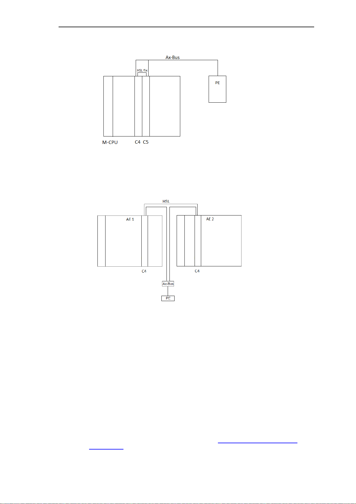
Example for CPU redundancy:
CPU redundancy with the predefined redundancy pair C-CPU 4 and 5 with fixed installed
HSL, the FUD runs for instance on both C-CPUs. The voting between both BSEs is performed
automatically by the M-CPU. The overview of a total system realized with CPU redundancy
can be found in section 1.2.1.3,
Connected.
Example for AU redundancy with SCA-RS:
SICAM AK - SICAM TM PE, Electrically and Optically
Global redundancy switchover: all SEs of an AU are switched active/passive.
Line-by-line redundancy switchover: the SEs of an AU are switched active/passive selectively.
Please note the distances between the AUs and SCA-RS, see detailed hardware
configurations in sections
1.3.1.1 ff.
20 Unrestricted SICAM RTUs, SICAM AK Redundancy
Edition 10.2016, DC2-026-2.07
Page 21
Redundancy via SCA-RS
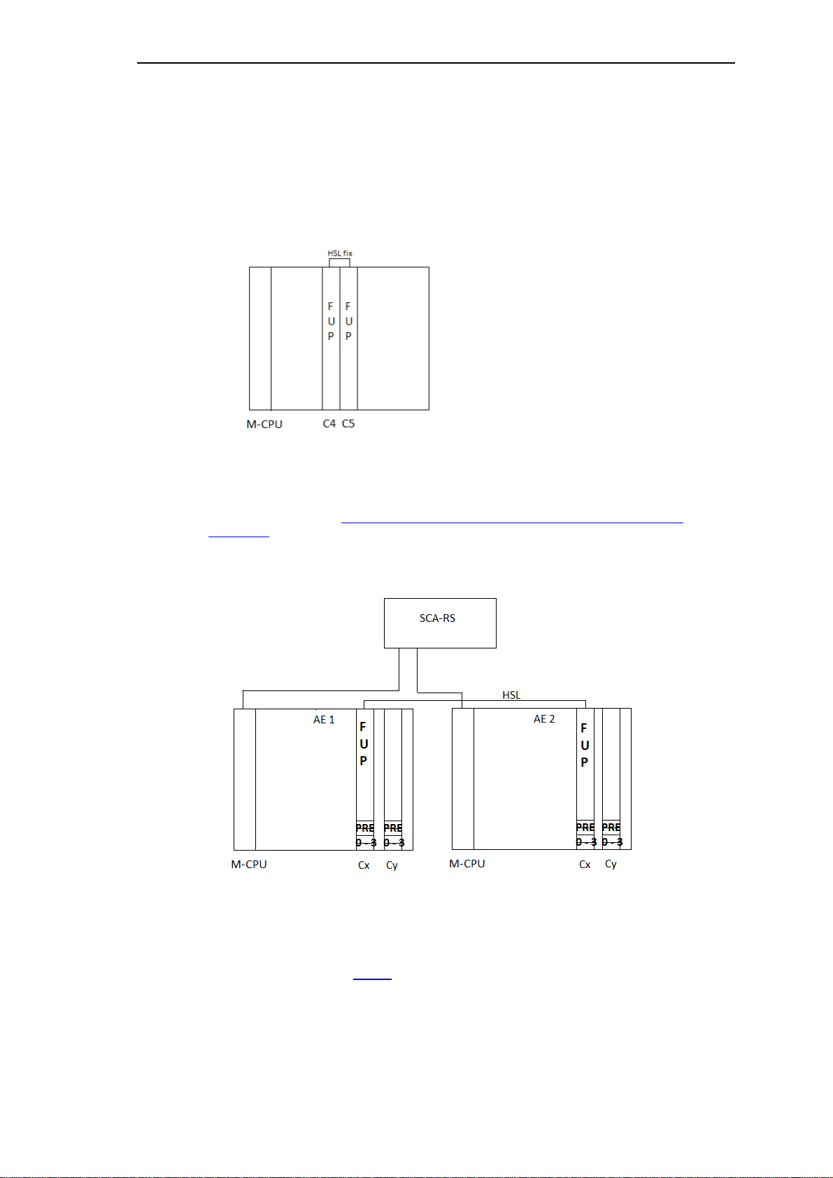
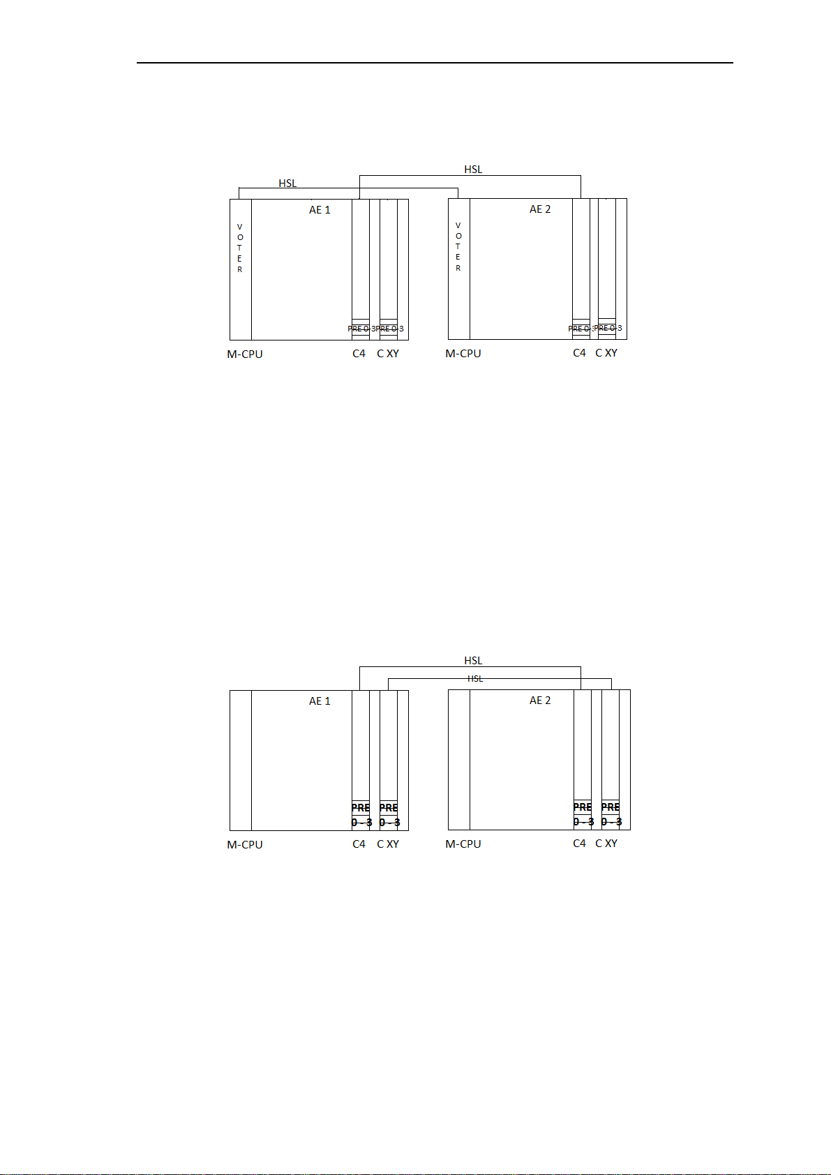
Example for AU redundancy with SCA-RS with application-related voting:
Global redundancy switchover: all SEs of an AU are switched active/passive.
Line-by-line redundancy switchover: the SEs of an AU are switched active/passive selectively.
The FUD runs for instance on both C-CPUs of the two AUs. The synchronization mode is High
Speed Link (HSL), if CAEx plus is used on both redundancy BSEs.
1.1.6 Overview of Synchronization Modes
Please note, that the representations are merely examples.
The 3 modes defined apply both for CPU as well as AU redundancy.
Example for AU redundancy:
The FUD runs for instance on both C-CPUs of the two AUs. The synchronization mode is High
Speed Link (HSL): if CAEx plus is used on both redundancy BSEs.
SICAM RTUs, SICAM AK Redundancy Unrestricted 21
DC2-026-2.07, Edition 10.2016
Page 22
Redundancy via SCA-RS
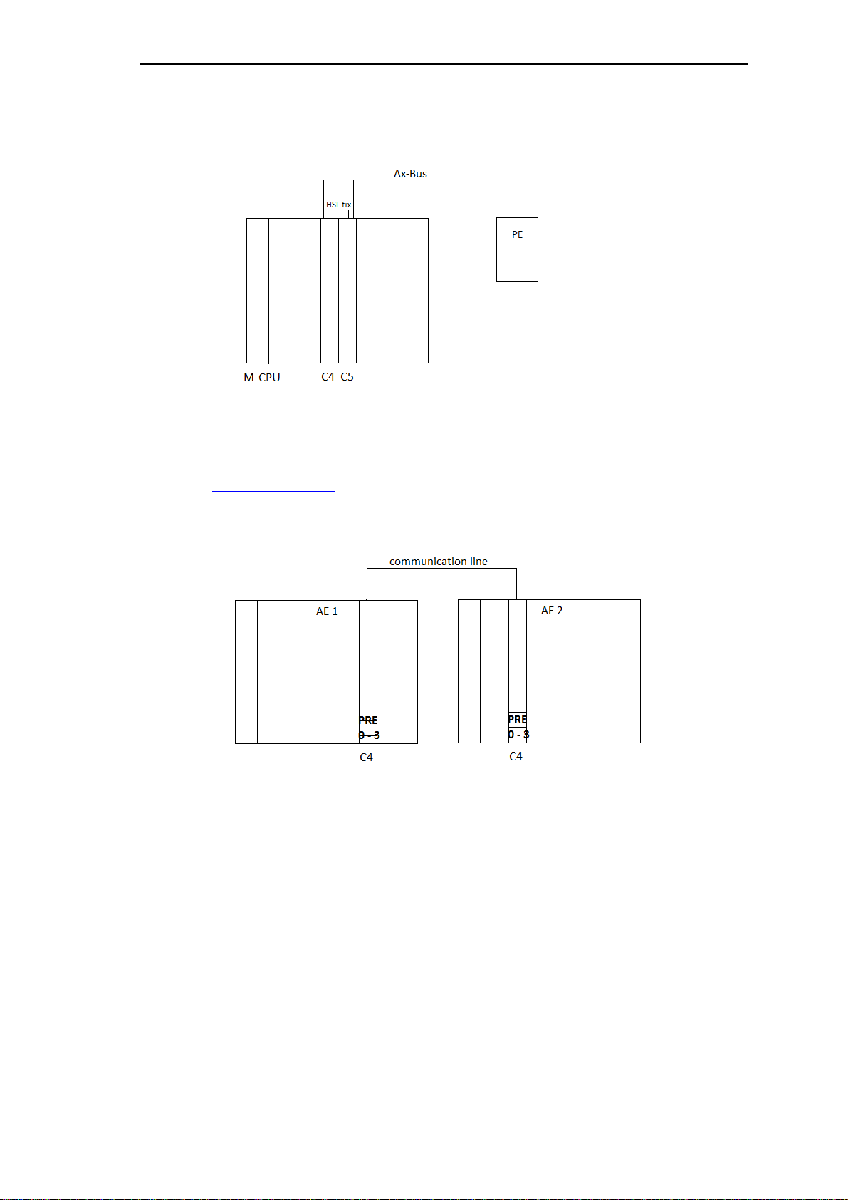
Example for CPU redundancy:
The FUD runs for instance on both C-CPUs of the AU. The synchronization mode is HSL with
singular Ax-PEs (here an example for CPU redundancy).
A detailed system overview can be found in section
1.2.1.1, SICAM AK - SICAM AK PE,
electrically connected.
Example for AU redundancy:
The synchronization mode i s Sync. via communication, if CAEx plus is used on both
redundancy BSEs.
If the distance between both AUs is more than 200 m, in all cases the redundancy
synchronization must take place over a separate fast data connection. In this case no singular
Ax-PEs are permitted.
22 Unrestricted SICAM RTUs, SICAM AK Redundancy
Edition 10.2016, DC2-026-2.07
Page 23

Redundancy via SCA-RS
1.2 CPU-Redundancy (Redundant Basi c System Elements)
The voting between both BSEs (between the redundant CPU pairs) is performed automatically
by the M-CPU (automatic voting with CPU redundancy).
You define the criteria for a voter switchover in the Redundancy Table (see also the
description of the Priority Levels in sections
Connection between both BSEs over HSL
The High Speed Link (HSL) is used for the synchronization of both redundant BSEs
(C-CPUs).
For CPU redundancy the HSL-connections are installed permanently at the back of the
mounting rack corresponding to the predefined CPU pairs.
Predefined BSE pairs 1/2, 4/5, 7/8, in the mounting rack for 9 slots (CM-2834).
Predefined BSE pairs 1/2, 4/5, 7/8, 10/11, 13/14 in the mounting rack for 17 slots (CM-2836).
1.2.3.2 ff.).
SICAM RTUs, SICAM AK Redundancy Unrestricted 23
DC2-026-2.07, Edition 10.2016
Page 24
Redundancy via SCA-RS
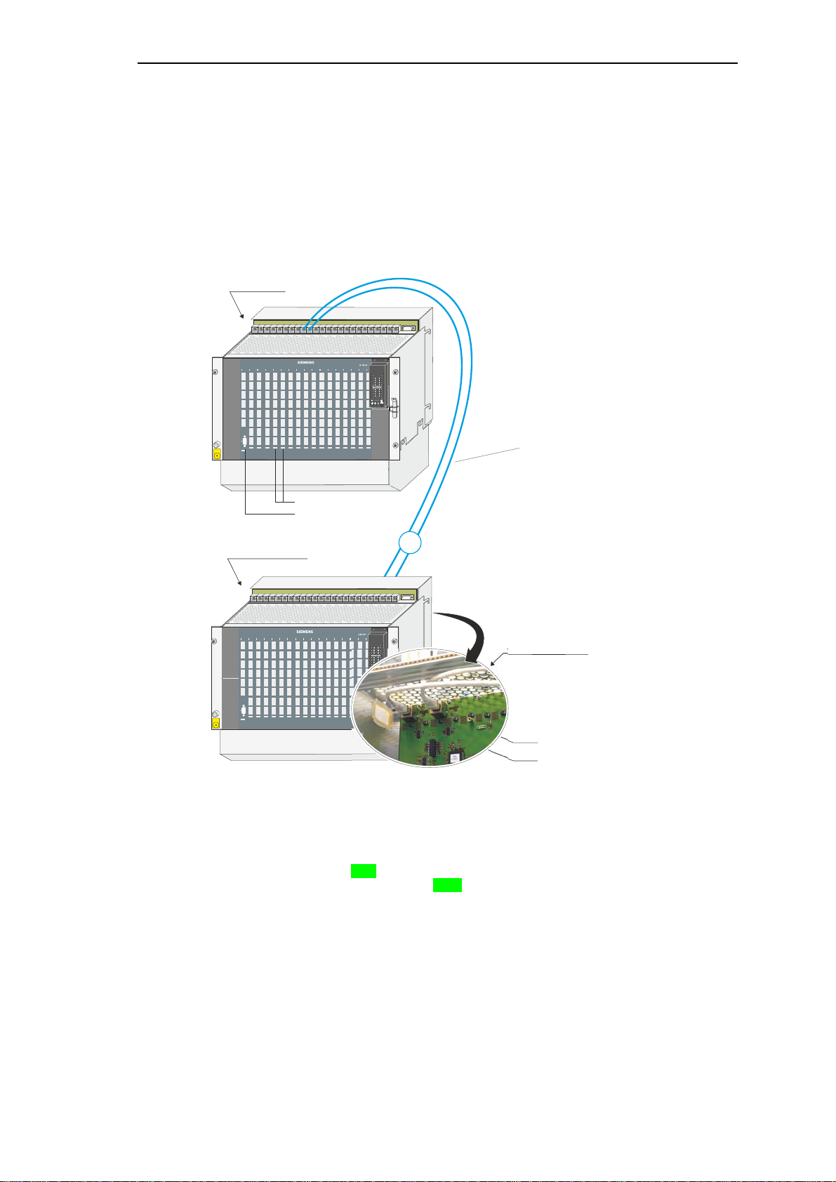
Ax 1703 peripheral bus (electrical)
16 Mbps
patch-cable, length up to 3 m
base unit
SICAM AK
peripheral elements
SICAM AK
(max. 16 PE)
back view CM-2833
ESD
EARTH
FACILITY
RYERRYERRYERRYERRYERRYERRYERRYERRYERRYERRYERRYERRYERRYERRYERRYERRY
ER
SICAM
PS-5620
CP-2014
CP-2017
1
Line 1
Line 2
ESD
EARTH
FACILITY
RYERRYERRYERRYERRYERRYERRYERRYERRYERRYERRYERRYERRYERRYERRYERRYERRY
ER
SICAM
PS-5620
1.2.1 Default Configurations
1.2.1.1 SICAM AK - SICAM AK PE, electrically connected
Base unit SICAM AK to peripheral elements SICAM AK PE, electrically connected.
• To one basic system element
CP-2017/PCCX25 one bus line with max.
16 peripheral elements can be connected
• The slots for the redundant BSE-pairs are
predefined, in fact: 1+2, 4+5, 7+8, (10+11,
13+14 only in 17 slots mounting rack), (green:
representation in the picture)
• Redundant BSEs have to have identical
configuration and identical functionality
• Depending on the slots of the basic system
elements the socket connectors for the
electrical Ax peripheral bus have to be
selected (for example: slots C4 and C5
socket connectors AXPE-C4 and AXPE-C5)
• If peri pheral elements are equi pped in the
base unit SICAM AK then those can be
driven either by the singular BSE CP-2014
or by the redundant BSEs CP-2017
24 Unrestricted SICAM RTUs, SICAM AK Redundancy
Edition 10.2016, DC2-026-2.07
Page 25

Necessary modules and cables
element
T41-252 (3m) / 6MF13040BC520AA0
Redundancy via SCA-RS
Base unit SICAM AK
Cable
Peripheral elements
SICAM AK
Designation Item Number / MLFB
CP-2017/PCCX25 Processing and communication
Patch cable Cat.5 (4x2) AWG26/7
CM-2833 SICAM AK board rack extension GC2-833 / 6MF11130CJ330AA0
BC2-017 / 6MF10130CA170AA0
T41-255 (1m) / 6MF13040BC550AA0
T41-251 (2m) / 6MF13040BC510AA0
SICAM RTUs, SICAM AK Redundancy Unrestricted 25
DC2-026-2.07, Edition 10.2016
Page 26
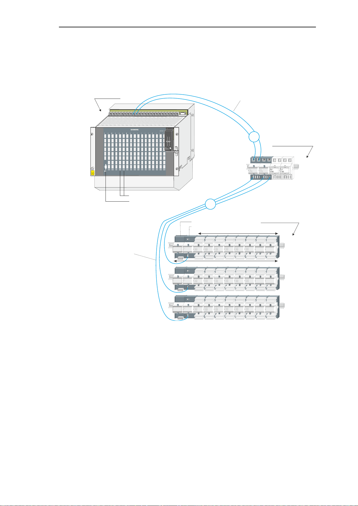
Redundancy via SCA-RS
I/O modules (max. 8)
Ax peripheral bus (electrical)
16 Mbps
patch-cable, length up to 3 m
Ax peripheral bus (electrical)
16 Mbps
USB-cable, length up to 3 m
bus interface modules
CM-0843
1 peripheral element
base unit
SICAM AK
peripheral elements
SICAM TM
(max. 16 PE)
ESD
EARTH
FACILITY
RYERRYERRYERRYERRYERRYERRYERRYERRYERRYERRYERRYERRYERRYERRYERRYERRY
ER
SICAM
PS-5620
PE-6410
PS-663x
CP-2014
CP-2017
(max. 4)
1
2
1.2.1.2 SICAM AK - SICAM TM PE, Electrically Connected
Base unit SICAM AK to peripheral elements SICAM TM, electrically connected.
• To one basic system element
CP-2017/PCCX25 one bus line with max.
16 peripheral elements can be connected
• The slots for the redundant BSE-pairs are
predefined, in fact: 1+2, 4+5, 7+8, (10+11,
13+14 only in 17 slots mounting rack)
• Redundant BSEs have to have identical
configuration and identical functionality
• I f peri pheral elements are equi pped in the
base unit SICAM AK then those can be driven
either by the singular BSE CP-2014 or by the
redundant BSEs CP-2017
• Depending on the slots of the basic system
• The bus interf ace modules CM-0843 are
elements the socket connectors for the
electrical Ax peripheral bus have to be
selected (for example: slots C4 and C5
socket connectors AXPE-C4 and AXPE-C5)
supplied by the power supplies PS-663x.
The power consumption of the CM-0843
(see technical data in data sheet) has to be
considered on the PS-663x
26 Unrestricted SICAM RTUs, SICAM AK Redundancy
Edition 10.2016, DC2-026-2.07
Page 27

Necessary modules and cables
Patch cable Cat.5 (4x2) AWG26/7
T41-255 (1m) / 6MF13040BC550AA0
CM-0843 Ax 1703-bus interface electrical
GA0-843 / 6MF11110AJ430AA0
USB-cable
TC6-201 (1,5m) / 6MF13130GC010AA0
TC6-203 (3m) / 6MF13130GC030AA0
PE-6410 peripheral coupling Ax-bus electrical
GC6-410 / 6MF11130GE100AA0
Redundancy via SCA-RS
Base unit
SICAM AK
Cable
Bus Interface
Modules
Cable
Peripheral
elements
SICAM TM
Designation Item Number / MLFB
CP-2017/PCCX25 Processing and
communication element
BC2-017 / 6MF10130CA170AA0
T41-251 (2m) / 6MF13040BC510AA0
T41-252 (3m) / 6MF13040BC520AA0
TC6-202 (2m) / 6MF13130GC020AA0
SICAM RTUs, SICAM AK Redundancy Unrestricted 27
DC2-026-2.07, Edition 10.2016
Page 28
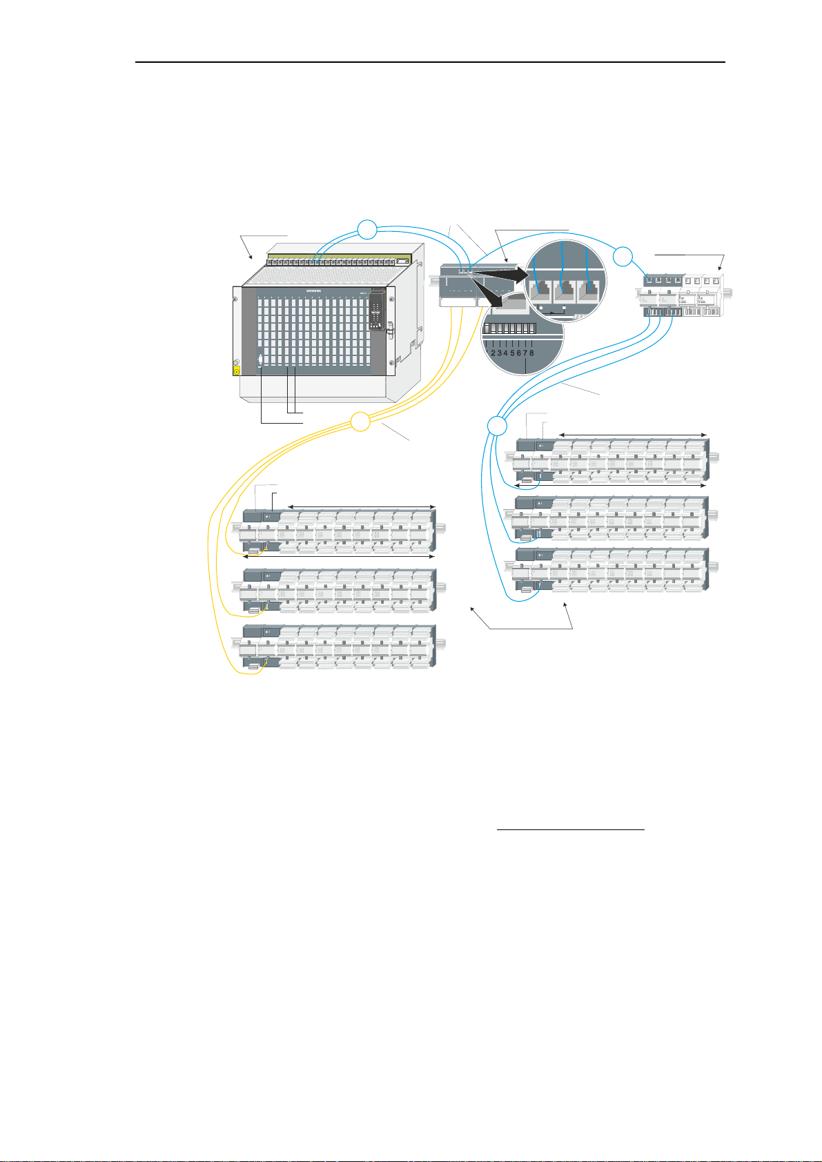
Redundancy via SCA-RS
I/O modules (max. 8)
Ax peripheral bus (electrical)
16 Mbps
patch-cable, length up to 3 m
Ax peripheral bus (optical)
16 Mbps
FO, length up to 200 m
I/O modules (max. 8)
Ax peripheral bus (electrical)
16 Mbps
USB-cable, length up to 3 m
1 peripheral element
1 peripheral element
bus interface modules
CM-0843
bus interface modules
CM-0842
base unit
SICAM AK
peripheral elements
SICAM TM
(max. 16 PE)
ESD
EARTH
FACILITY
RYERRYERRYERRYERRYERRYERRYERRYERRYERRYERRYERRYERRYERRYERRYERRYERRY
ER
SICAM
PS-5620
PE-6410
PS-663x
PE-6411
PS-663x
CP-2014
CP-2017
3
2
SICAM
1703
SICAM
1703
ON
OFF
S1
BSE
LINE1
RED
X4 X5 X6
Tx 1:1
B
S
E
1
C
M
-
0
8
4
3
B
S
E
2
1
1
1.2.1.3 SICAM AK - SICAM TM PE, Electrically and Optically Connected
Base unit SICAM AK to peripheral elements SICAM TM, electrically and optically connec ted.
• To one basic system element
CP-2017/PCCX25 one bus line with max.
16 peripheral elements can be connected
• The slots for the redundant BSE-pairs are
predefined, in fact: 1+2, 4+5, 7+8, (10+11,
13+14 only in 17 slots mounting rack)
• Depending on t he sl ots of the basic system
elements the socket connectors for the
electrical Ax peripheral bus have to be
selected (for example: slots C4 and C5
socket connectors AXPE-C4 and AXPE-C5)
• The bus interface modules CM-0843 are
supplied by the power supplies PS-663x. The
power consumption of the CM-0843 (see
technical data in data sheet) has to be
considered on the PS-663x
• In configurations with optical remote
SICAM TM PEs 1000 µm-fibre cables
cannot be used!
• Redundant BSEs have to have identical
configuration and identical functionality
• Each bus interface module CM-0842 has to
be supplied separately. (18 VDC...78 VDC)
• Configuration switch CM-0842
1 ....... F1/F2 ....... ON ...... 16 MBit
2 ....... LINE2 ....... OFF ..... PE(O)
3 ....... AS2 .......... OFF ..... 0
4 ....... AS1 .......... OFF ..... 0
5 ....... AS0 .......... OFF ..... 0
6 ....... RED ......... ON ...... BSE
7 ....... LAD .......... OFF ..... inactive
8 ....... LINE1 ....... ON ...... 1:1
28 Unrestricted SICAM RTUs, SICAM AK Redundancy
Edition 10.2016, DC2-026-2.07
Page 29

Necessary modules and cables
Patch cable Cat.5 (4x2) AWG26/7
T41-255 (1m) / 6MF13040BC550AA0
CM-0843 Ax 1703-bus interface electrical
GA0-843 / 6MF11110AJ430AA0
TC6-201 (1,5m) /
TC6-203 (3m) / 6MF13130GC030AA0
FO-INDOORCABLE-200-DUP-BREAK-ROUND
TF7-035
FO-OUTDOORCABLE-200-2FIB-ARM
(only for outdoorcableTF7-036)
TF7-036
PE-6411 peripheral coupling Ax-bus 1x optical
GC6-411 / 6MF11130GE110AA0
Redundancy via SCA-RS
Base unit
SICAM AK
Cable
Bus interface
modules
electrical
optical
Cable
electrical
Cable
optical
Peripheral
elements
SICAM TM
electrical
optical
Designation Item Number / MLFB
CP-2017/PCCX25 Processing and communication
element
CM-0842 Ax 1703-bus interface 4x FO GA0-842 / 6MF11110AJ420AA0
USB-cable
FO-CONNECTOR-ODLP-200 (2 pcs. per connection)
FO-CONNECTOR-ODLP-200 (2 pcs. per connection)
FO-PIPE SPLITTER 2Y-LR1 (2 pcs. per connection)
PE-6410 peripheral coupling Ax-bus electrical GC6-410 / 6MF11130GE100AA0
BC2-017 / 6MF10130CA170AA0
T41-251 (2m) / 6MF13040BC510AA0
T41-252 (3m) / 6MF13040BC520AA0
6MF13130GC010AA0
TC6-202 (2m) / 6MF13130GC020AA0
TF7-015
TF7-015
TF7-066
SICAM RTUs, SICAM AK Redundancy Unrestricted 29
DC2-026-2.07, Edition 10.2016
Page 30
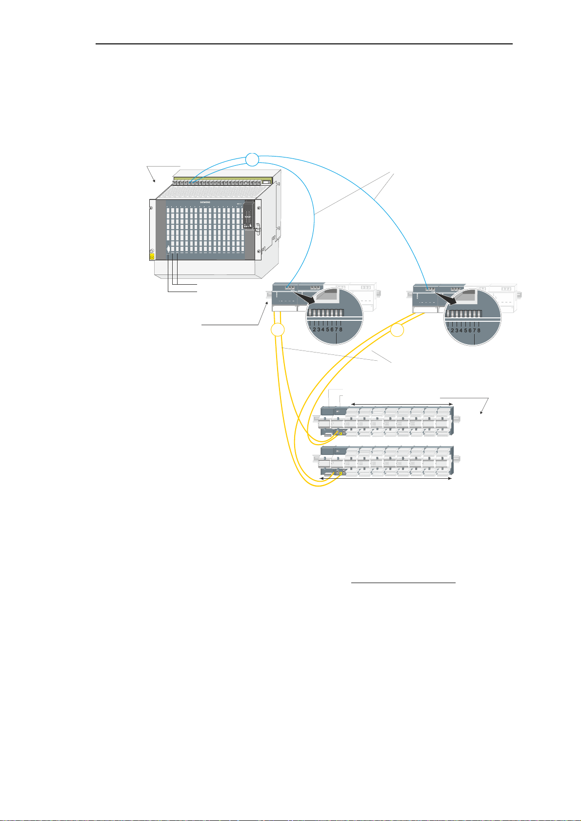
Redundancy via SCA-RS
I/O modules (max. 8)
Ax peripheral bus (electrical)
16 Mbps
patch-cable, length up to 3 m
1 peripheral element
Ax peripheral bus (optical)
16 Mbps
FO, length up to 200 m
bus interface modules
CM-0842
base unit
SICAM AK
peripheral elements
SICAM TM
(max. 16 PE)
ESD
EARTH
FACILITY
RY
ER
RY
ER
RY
ER
RY
ER
RY
ER
RY
ER
RY
ER
RY
ER
RY
ER
RY
ER
RY
ER
RY
ER
RY
ER
RY
ER
RY
ER
RY
ER
RY
ER
SICAM
PS-5620
PE-6412
PS-663x
CP-2014
CP-2017
2
2
S
ICA
M
1
703
SICAM
1
703
ON
OFF
S1
S
IC
AM
170
3
SI
CAM
1
70
3
ON
OFF
S1
1
1.2.1.4 SICAM AK - SICAM TM PE, Optical, Red. BSE + Red. Ax-PE-Bus
Base unit SICAM AK to peripheral elements SICAM TM, optically connected, redundant bas i c
system elements and redundant Ax-PE-Bus.
• To one basic system element
CP-2017/PCCX25 one bus line with max.
16 peripheral elements can be connected
• The slots for the redundant BSE-pairs are
predefined, in fact: 1+2, 4+5, 7+8, (10+11,
13+14 only in 17 slots mounting rack)
• Depending on t he sl ots of the basic system
elements the socket connectors for the
electrical Ax peripheral bus have to be
selected (for example: slots C1 and C2
socket connectors AXPE-C1 and AXPE-C2)
• I n conf i gurat i ons with optic al remote
SICAM TM PEs 1000 µm-fibre cables cannot
be used!
• Redundant BSEs have to have identical
• Att ention: B reak of an FO-connection leads
to a failure of the peripheral elements
PE-6412 until the redundant basic system
element duly assumes the function
During this time connection to the peripheral
elements PE-6412 does not exist
• Configuration switch CM-0842
1 ....... F1/F2 ....... ON ...... 16 MBit
2 ....... LINE2 ....... OFF ..... PE(O)
3 ....... AS2 .......... OFF ..... 0
4 ....... AS1 .......... OFF ..... 0
5 ....... AS0 .......... OFF ..... 0
6 ....... RED ......... OFF ..... CM-0842
7 ....... LAD .......... OFF ..... inactive
8 ....... LINE1 ....... ON ...... PE
configuration and identical functionality
• Each bus interface module CM-0842 has to be
supplied separately (18 VDC...78 VDC)
30 Unrestricted SICAM RTUs, SICAM AK Redundancy
Edition 10.2016, DC2-026-2.07
Page 31

Necessary modules and cables
element
6MF13040BC520AA0
CM-0842 Ax -bus interface 4x FO
GA0-842 / 6MF11110AJ420AA0
FO-CONNECTOR-ODLP-200 (2 pcs. per connection)
TF7-015
(only for outdoor cable TF7-036)
PE-6412 peripheral coupling Ax-bus 2x optical
GC6-412 / 6MF11130GE120AA0
Central Fiber Switch
Cable
Patch cable, max. length 10 m
Plenum cable, max. length 90 m
11 1
Switch Switch Switch
11 1
ESD
EARTH
FACILITY
RYERRYERRYERRYERRYERRYERRYERRYERRYERRYERRYERRYERRYERRYERRYERRYERRY
ER
SICAM
PS-5620
CP-2014
CP-2017
IEC 69870-5-104
SICAM AK
Redundancy via SCA-RS
Base unit SICAM AK
Cable
Designation Item Number / MLFB
CP-2017/PCCX25 Processing and communication
Patch cable Cat.5 (4x2) AWG26/7
BC2-017 / 6MF10130CA170AA0
T41-255 (1m) /
6MF13040BC550AA0
T41-251 (2m) /
6MF13040BC510AA0
T41-252 (3m) /
Bus interface
modules
Cable
Peripheral elements
FO-INDOORCABLE-200-DUP-BREAK-ROUND
FO-OUTDOORCABLE-200-2FIB-ARM
FO-CONNECTOR-ODLP-200 (2 pcs. per connection)
FO-PIPE SPLITTER 2Y-LR1 (2 pcs. per connection)
TF7-035
TF7-036
TF7-015
TF7-066
SICAM TM
1.2.2 Data Transfer Between Redundant BSE Pairs
• Data exchange bet ween the redundant BSEpairs is carried out only external via Ethernet
• On eac h CP-2017 a SM-2556 has to be
equipped
• The slots for the redundant BSE-pairs are
predefined, in fact: 1+2, 4+5, 7+8, (10+11,
13+14 only in 17 slots mounting rack). (green:
representation in the picture)
• The el ect ri cal connection between Central
Fibre Switch and SICAM 1703 component can
be up to 100 m
SICAM RTUs, SICAM AK Redundancy Unrestricted 31
DC2-026-2.07, Edition 10.2016
• Depending on the slots of the basic system
elements the socket connectors for the
electrical Ax peripheral bus have to be
selected (for example: slots C1 and C2
socket connectors AXPE-C1 and AXPE-C2)
• Power supply has to be redundant!
• Redundant BSEs have to have identical
configuration and identical functionality
Page 32

Redundancy via SCA-RS
CM-2838 connection communication (CP-2017)
BC2-838 / 6MF10130CJ380AA0
SM-2556/ETA2
BC2-556 / 6MF10130CF560AA0
CM-2860 patch plug standard V28,ET,TR
CA2-860 / 6MF12110CJ600AA0
Patch cable Cat.5 (4x2) AWG26/7
T41-255 (1m) / 6MF13040BC550AA0
Necessary modules and cables
CP-2017 processing and communication
Base unit
SICAM AK
Cable
Processing and communication element
CP-2017/PCCX25
1.2.3 Parameter Setting
Firmware versions (status 10/2013):
M: CP-2014/CPCX25 (Master Control Element)
C4: CP-2017/PCCX25 (Processing and Communication Element)
C5: CP-2017/PCCX25 (Processing and Communication Element)
Designation Item Number / MLFB
BC2-017 / 6MF10130CA170AA0
T41-251 (2m) / 6MF13040BC510AA0
T41-252 (3m) / 6MF13040BC520AA0
T41-253 (5m) / 6MF13040BC530AA0
T41-254 (10m) / 6MF13040BC540AA0
1.2.3.1 Parameter Setting of the CP-2014/CPCX25
• In the OPM system technique select Redundancy Control under the Redundancy node
below the M-CPU:
• In the Value dropdown list select the entry CPU-Redundancy.
Other selection options:
• No redundancy
The following options are intended for redundant AUs:
• Global redundancy switchover with SCA-RS
• Global redundancy switchover with application-related voting
• Line-by-line redundancy switchover with SCA-RS
• Line-by-line redundancy switchover with application-related v oting
32 Unrestricted SICAM RTUs, SICAM AK Redundancy
Edition 10.2016, DC2-026-2.07
Page 33

Redundancy via SCA-RS
• In the OPM system technique select Red_sync mode under the Redundancy node below
the M-CPU:
• In the Value column for the parameters Red_sync mode and Red_sync org_img select
one of the following entries from the dropdown l ist:
Please note, that some parameters are available for all types of redundancy control (global
redundancy switchover with SCA-RS, global redundancy switchover with application-related
voting, line-by-line redundancy switchover with SCA-RS, line-by-line redundancy switchover
with application-related voting), unless explicitly specified otherwise in the column “Comment”.
Column name/
Description/Value Comment
Parameter
Red_sync mode
No synchronization: if no CAEx plus is used on
this BSE and also no singular Ax-PE is
coupled
High Speed Link (HSL): if CAEx plus is used
on both redundancy BSEs
HSL with singular Ax-PEs: if a singular Ax -PE
is coupled on this BSE. The CAEx plus
application is also synchronized over the HSL
Sync. via communication:
If the distance between both AUs is more than
200 m, the redundancy synchronization must
also be performed over a separate fast data
connection. In this case no singular Ax-PEs
are allowed.
Red_sync org_img One element of the redundancy pair must be
defined as Original, the other as Image.
This parameter defines, whether this BSE is to
be the Original or the Image element of the
redundancy pair.
The second element of the redundancy pair
must be defined at Address of the redundant
BSE (see below)
Specific settings for
redundant AUs, not
relevant with CPU
redundancy
The mirroring of the
parameter is otherwise not
possible.
SICAM RTUs, SICAM AK Redundancy Unrestricted 33
DC2-026-2.07, Edition 10.2016
Page 34

Redundancy via SCA-RS
• In the OPM system technique select Redundancy buffer under the node Redundancy
below the M-CPU:
The redundancy buffer is used to avoid the loss of data during the occurrence of an
error/failure until the redundancy switchover is complete.
Column name/
Parameter
Global enabling
Buffer size
Buffer time
The parameter group Redundancy buffer is also available on the CP-2017/PCCX25.
The following parameter groups are identical with those on the C:CPU:
• Address of the redundant BSE
• Synchronization parameters
• Singular Ax-PEs
Refer to section 1.4,
Description/Value Comment
disabled
enabled
Maximum number of process information
items, that can also be stored in the Buffer
time.
Maximum time, during which the process
information items should also be stored.
Parameter Setting of the CP-2017/PCCX25.
1-32000
1-255 Seconds
1.2.3.2 Automatic Voting
Every system has 15 priority levels (0 to 14), whereby 14 is the highest level.
The Voter evaluates both redundancy systems based on the defined number and the priority
levels. The Voter interprets the subsystem with the higher priorities as the faulty one and
switches over to the other system.
You define the criteria for a Voter switchover!
(The priorities can also be defined with the help of CAEx plus, according to the requirements
of your total system.)
The Voter compares the statuses of both systems, by starting from the highes t priority
level 14. If both systems have the same status, the Voter compares both systems based on
the next lower priority level.
34 Unrestricted SICAM RTUs, SICAM AK Redundancy
Edition 10.2016, DC2-026-2.07
Page 35

Redundancy via SCA-RS
Error/
Option
a Priority 14 Priority 14 No (the active redundancy system 1
b Not used Not used No (the active redundancy system 1
c Priority 13 Priority 12 Yes (the active redundancy system 1 is
c Priority 13 Not used Yes (the active redundancy system 1 is
c Priority 13 Priority 14 No (the active redundancy system 1
Active Redundancy
System 1
“Not used” means, that no priority is assigned, i.e. in the event of a failure or fault, the Voter
does not evaluate the error concerned. Therefore, there is also no switchover in the respective
case.
Passive
Redundancy
System 2
or
or
Switchover
continues to remain active)
continues to remain active)
switched to passive)
switched to passive)
continues to remain active)
1.2.3.3 Settings for PREs (CPU Redundancy)
You define, which errors in the system are assigned which priority.
This is how you define the criteria for automatic Voting:
• Select Settings for PREs (CPU Redundancy):
SICAM RTUs, SICAM AK Redundancy Unrestricted 35
DC2-026-2.07, Edition 10.2016
Page 36

Redundancy via SCA-RS
• Click in the table and in the context menu select Unhide columns -> all, to see other
hidden columns (with other optional parameters):
• Search for the rows of the corresponding CPU pair (in the example, the redundancy pair
C4/C5-CPU
Therefore for the next step of processing the rows 4 to 7 are relevant, that depends on the
configuration of your AU.
Please note, that some parameters are available for all types of redundancy control (global
redundancy switchover with SCA-RS, global redundancy switchover with application-related
voting, line-by-line redundancy switchover with SCA-RS, line-by-line redundancy switchover
with application-related voting), unless explicitly specified otherwise in the column “Comment”.
• In the rows concerned select the values required from the dropdown list
36 Unrestricted SICAM RTUs, SICAM AK Redundancy
Edition 10.2016, DC2-026-2.07
Page 37

Settings for PREs (CPU Redundancy)
Defines, whether the Voter (the M:CPU)
Redundancy via SCA-RS
Column name/
Description/Value Comment
Parameter
DR# Not editable
DB Not editable
CPU-pair Predefined CPU-pairs for the redundancy Not editable
PRE In each case four PREs (0 – 3) per CPU-pair Not editable
Priority PRE failure Definition of the priority level for the failure of
the PRE concerned (hardware or firmware
damage)
To be defined for all four
PREs (0–3).
Available for: CPU
redundancy and line-by-line
redundancy switchover with
SCA-RS
Priority
communication
Definition of the priority level for the fai lure of
the communication on the PRE concerned
To be defined for all four
PREs (0–3).
failure
Priority
communication fault
Priority assignment See following section
Definition of the priority level for
communication fault on the PRE concerned
To be defined for all four
PREs (0–3).
Specific setting for AUredundancy (line-by-line
redundancy switchover
with SCA-RS)
Can be defined for all PREs
for every BSE of the AU (MCPU and 16 C-CPUs).
Option: switchable
Option: prefered
position
Option: general
interrogation
should switch over the PRE of the redundancy
pair concerned (system element is being
switched passive) or not (system element is
not being switched passive)
See following section
Defines, whether a GI is to be sent after the
switchover of the relevant PRE to active (GI
after active) or not (no GI after active)
The option entered defines
the action of the voter; not
available for line-by-line
redundancy switchover with
application-related voting
Specific setting for line-byline redundancy
switchover with
application-related voting
Can be defined for all PREs
for every BSE of the AU (MCPU and 16 C-CPUs).
SICAM RTUs, SICAM AK Redundancy Unrestricted 37
DC2-026-2.07, Edition 10.2016
Page 38

Redundancy via SCA-RS
Note
Please note, that the settings are valid for the entire BSE. The values for these settings should be
selected higher than
Settings for PREs (CPU Redundancy)
Column name/
Description/Value Comment
Parameter
Option: user data
filter
Defines the behavior of the PRE (when
passive)
Filter only user data with Status R
if system element passive, filter user data
Option: user data
filter deact
User data filter deactivated: the PRE
sends/receives all data, including user data
User data filter activated: the PRE
sends/receives the user data defined in the
filter (column before).
1.2.3.4 Settings for BSEs (CPU Redundancy)
The filter relates only to the
transmit direction. Filtering
means, that the data point
will not be sent
The passive PRE
sends/receives only
messages with the status bit
R set (R-Bit = Redundancy)
The passive PRE continues
to send/receive all messages
with user data
Definition, whether the filter
should be activated or not.
the values of the corresponding settings for the PREs.
This is how you define the criteria for automatic Voting:
• Select Settings for BSEs (CPU Redundancy), to edit the table
• Click in the table and in the context menu select Show columns -> all, to see other hidden
columns (with other optional parameters)
• Search for the rows of the corresponding CPU pair (in the example, the redundancy pair
C4/C5-CPU
• Edit the required values in the rows concerned (row 1 C4/C5-CPU):
Please note, that some parameters are available for all types of redundancy control (global
redundancy switchover with SCA-RS, global redundancy switchover with application-related
voting, line-by-line redundancy switchover with SCA-RS, line-by-line redundancy switchover
with application-related voting), unless explic itly specified otherwise in the column “Comment”.
38 Unrestricted SICAM RTUs, SICAM AK Redundancy
Edition 10.2016, DC2-026-2.07
Page 39

Settings for BSEs (CPU Redundancy)
Redundancy via SCA-RS
Column name/
Parameter
DR# Not editable
DB Not editable
CPU-pair Predefined CPU-pairs Not editable
Priority BSE failure Definition of the priority level for the failure
of the BSE concerned (hardware or firmware
damage)
Delay after BSE failure Definition of the time period, after the expiry
of which the priority is canceled for a BSE
failure following a going BSE failure (in
seconds)
Priority BSE task
suspend
Priority PE failure Definition of the priority level, when the PE
Priority assignment See following section
Definition of the priority level, when a
CAEx plus task is stopped
fails (hardware or firmware damage or PE
not coupled)
Description/Value Comment
To edit: double click in the
field and enter the required
value (0-254)
Specific setting for AUredundancy (line-by-line
redundancy switchover
with SCA-RS)
Option: switchable See following section
Option: preferred
position
Option: type of use
See following section
singular
redundant
Specific setting for AUredundancy (line-by-line
redundancy switchover
with SCA-RS, global
redundancy switchover
with SCA-RS, global
redundancy switchover
with application-related
voting)
Specific setting for AUredundancy (line-by-line
redundancy switchover
with application-related
voting
Specific settings for CPU
Redundancy
The CPUs of the predefined
CPU pairs 1/2, 4/5 etc.
(connected via fixed
installed HSL at the back of
the module rack) can each
be a singular CPU, which
can then not be switched
over.
The predefined CPU pairs
are used as such.
Option: general
interrogation
SICAM RTUs, SICAM AK Redundancy Unrestricted 39
DC2-026-2.07, Edition 10.2016
Defines, whether a GI is to be sent after the
switchover of the relevant BSE to active (GI
after active) or not (no GI after ac tive)
Page 40

Redundancy via SCA-RS
Settings for BSEs (CPU Redundancy)
Column name/
Parameter
Option: User data filter
to PE
Option: user data filter
deact
For the parameter setting of C4 and C5: CP-2017/PCCX25 for CPU redundancy, refer to
section 1.4, Parameter Setting of the CP-2017/PCCX25.
Description/Value Comment
Defines the behavior of the BSE (when
passive)
Filter only user data with Status R: the
passive BSE sends only messages with that
status bit set
if system element passive, filter user data:
The passive BSE continues to send/receive
all messages with user data to/from the
corresponding PE in the AU.
User data filter deactivated: the BSE
sends/receives all data, including user data
to the corresponding PE.
User data filter activated: the BSE sends the
user data defined in the filter (column before)
to the corresponding PE in the AU.
The filter relates only to the
transmit direction. Filtering
means, that the data point
will not be sent
The passive BSE
sends/receives only
messages with the status bit
R set (R-Bit = Redundancy),
The passive BSE continues
to send/receive all
messages with user data
Definition, whether the filter
should be activated or not.
40 Unrestricted SICAM RTUs, SICAM AK Redundancy
Edition 10.2016, DC2-026-2.07
Page 41

1.3 Redundant Automation Units
Connection between both BSEs over HSL:
The High Speed Link (HSL) is used for the synchronization of both redundant BSEs
(C-CPUs).
In the case of AU redundancy the HSL is established with a fiber optic cable.
Exception: If the distance between both AUs is more than 200 m, in all cases the redundancy
synchronization must take place over a separate fast data connection.
That causes a high load in the AU. Therefore take the following into consideration:
• Parameterize a connection between both AUs on that PRE, that is to be responsible for
the synchronization of both BSEs
• The PRE for this data connection must be coupled to that BSE which is to be
synchronized.
• Use cycle times that are long enough for your CAEx plus application
• Make sure, that both BSEs have an identical configuration and that they are loaded with
the same FW revision and the same parameters (state).
Redundancy via SCA-RS
SICAM RTUs, SICAM AK Redundancy Unrestricted 41
DC2-026-2.07, Edition 10.2016
Page 42

Redundancy via SCA-RS
SCA-RS Voter
Automation unit
SICAM AK
Ethernet
Cable
CM-1820
TB cable
length 15 m
Cable
Patch cable
Cable
High speed link
FO, max. length 200 m
redundancy syncrhonization
via High Speed Link
see the sections“Redundant Basic System Elements”
“Redundant AUs in ring configurations”
“Redundant AUs in star configurations”
and
and
to the remote
peripheral elements
to the slaves
ESD
EARTH
FACILITY
RYERRYERRYERRYERRYERRYERRYERRYERRYERRYERRYERRYERRYERRYERRYERRYERRY
ER
SICAM
PS-5620
ESD
EARTH
FACILITY
RYERRYERRYERRYERRYERRYERRYERRYERRYERRYERRYERRYERRYERRYERRYERRYERRY
ER
SICAM
PS-5620
2
2
PS-5620PS-5620
SCA-RS
SCA-RS
IEC 69870-5-104
1 1
3
1.3.1 Default Configurations
1.3.1.1 Redundant AUs, Voting by SCA-RS, Distance up to 15 m
• Redundanc y s ync hroni zat i on of function
diagram and of the periphery is executed by a
high speed link
• A hi gh speed link is essential with singular
periphery
• The electrical connection between Ethernet
and SICAM RTUs component can be up to
100 m
42 Unrestricted SICAM RTUs, SICAM AK Redundancy
Edition 10.2016, DC2-026-2.07
• Depending on the slots of the basic system
elements the socket connector for the H.S.L.
connection has to be selected (e.g. slot C0
socket connector HSL-C0)
The following socket connectors are
available: HSL-C0 and C1, in the small rack
CM-2832 and additional C4, C7, C10, C13 in
the large rack CM-2836
• SCA-RS is connect ed to SICAM AK via the
socket connector SYS-IO on the SICAM AK
Page 43

Necessary modules and cables
Redundancy via SCA-RS
SCA-RS Voter
SICAM AK
Cable
Cable
Cable
Designation Item Number / MLFB
CM-2816 redundancy board rack for AK 1703
PS-5620 Power Supply 24…60 VDC/80 W or
PS-5622 Power Supp.110…220 VDC, 230 VAC/80 W
SCA-RS redundancy switch
EPROM RED25
CP-2014 system function, processing and
communication
CM-2839connect comm./sys-I/O (CP-2014)
CP-2017 processing and communication
CM-2838 connection communication (CP-2017)
SM-2556/ETA2 BC2-556 / 6MF10130CF560AA0
CM-2860 patch plug standard V28,ET,TR CA2-860 / 6MF12110CJ600AA0
CM-0828 fiber-optic-interface (TTL-LWL)
2 pcs. for SCA-RS connection
2 pcs. for high speed link
CM-1820 TB cable BA1-820 / 6MF10110BJ200AA0
Patch cable CAT5 (4x2) AWG26/7
FO-INDOORCABLE-200-DUP-BREAK-ROUND
FO-CONNECTOR-ODLP-200 (2 pcs. per connection)
FO-OUTDOORCABLE-200-2FIB-ARM
FO-CONNECTOR-ODLP-200 (2 pcs. per connection)
FO-PIPE SPLITTER 2Y-LR1 (2 pcs. per connection)
(only for outdoor cable TF7-036)
GA2-816 / 6MF11110CJ160AA0
BC5-620 /6MF10130FG200AA0
BC5-622 / 6MF10130FG220AA0
B70-010 / 6MF10070AA100AA0
SC2-051* / 6MF14130CA510AA2
BC2-014 / 6MF10130CA140AA0
BC2-839 / 6MF10132CJ300AA0
BC2-017 / 6MF10130CA170AA0
BC2-838 / 6MF10130CJ380AA0
GA0-828 / 6MF11110AJ280AA0
T41-255 (1m) / 6MF13040BC550AA0
T41-251 (2m) / 6MF13040BC510AA0
T41-252 (3m) / 6MF13040BC520AA0
T41-253 (5m) / 6MF13040BC530AA0
T41-254 (10m) / 6MF13040BC540AA0
TF7-035
TF7-015
TF7-036
TF7-015
TF7-066
SICAM RTUs, SICAM AK Redundancy Unrestricted 43
DC2-026-2.07, Edition 10.2016
Page 44

Redundancy via SCA-RS
cabinet 1
component 1
wall socket or
patch panel
cabinet 2
component 2
wall socket or
patch panel
plenum cable, ca. 100 m
TF5-010
RJ45
TF5-200 (1,5m)
TF5-201 (3m)
TF5-202 (5m)
RJ45
TF5-200 (1,5m)
TF5-201 (3m)
TF5-202 (5m)
Establishing an electrical connection with a cable longer than 10 m
If it is necessary to lay a more than 10 m long el ectrical cable (up to max. 100 m)
a plenum cable has to be used.
Such a connection occurs in the following configurations in this document:
• Point-to-point-traffic electrical (max. 15 m with V.28)
• Multi-point traffic electrical (max. 15 m with V.28)
• LAN communication electrical (max. 100 m with Ethernet)
Necessary modules and cables
Designation Item Number / MLFB
Cable
Plenum cable
Patch panel TP_Patch panel 24 Port 1HU, 6M T41-269 / 6MF13042BC600AA1
X-Port STP Box Cat.5e screened (4, 8, 12 Port) TEL+TS53.....
Wall socket
Installation cable Cat.5 (4x2x0.5) AWG24
RJ-45/open end
Installation cable Cat.5 (4x2x0.5) AWG24
Installation via wall socket or patch field
TP_socket 2 x RJ-45 30° AP Cat.5
TP_connection module 1 x RJ-45 Cat.5
Assembly base for TS35
TF5-200 (1.5m) / 6MF13140FC000AA1
TF5-201 (3m) / 6MF13140FC010AA1
TF5-202 (5m) / 6MF13140FC020AA1
TF5-010 / 6MF13140FA100AA1
T41-286 / 6MF13040BC860AA1
T41-287 / 6MF13040BC870AA1
T41-291 / 6MF13041BC010AA1
44 Unrestricted SICAM RTUs, SICAM AK Redundancy
Edition 10.2016, DC2-026-2.07
Page 45

Redundancy via SCA-RS
3
1
HSA 50S24-PHSA 50S24-P
2
2
2
2
1
4
SCA-RS Voter
Automation unit
SICAM AK
Ethernet
Cable
CM-1820
TB cable
length 15 m
Cable
Patch cable
Cable
High speed link
FO, max. length 200 m
MOXA NPort IA5150
with power supply
MOXA NPort IA5150
with power supply
Connector
UN1373-1B
back view CM-2816
CM-1820 TB cable
UN 1373-1B
UN 1373-1B
redundancy synchronization
via High Speed Link
see the sections“Redundant Basic System Elements”
“Redundant AUs in ring configurations”
“Redundant AUs in star configurations”
and
and
to the remote
peripheral elements
to the slaves
IEC 69870-5-104
Cable
FO-cable indoor
1000 DUP (max. 15 m)
2 x Connector
UN 1373-1B
1.3.1.2 Redundant AUs, Voting by SCA-RS, Distance up to 200 m
Implemented with the third party product MOXA Nport Server:
• Redundanc y s ync hroni zat i on of function
diagram and of the periphery is executed by a
high speed link
• A hi gh speed link is essential with singul ar
periphery
• SCA-RS is connected to SICAM AK via the
socket connector SYS-IO on the SICAM AK
• The el ect ri cal connection between Ethernet
and SICAM RTUs component or between
Ethernet and MOXA-Server can be up to
100 m
• Depending on the slots of the basic system
elements the socket connector for the H.S.L.
connection has to be selected (e.g. slot C0
socket connector HSL-C0)
The following socket connectors are
available: HSL-C0 and C1, in the small rack
CM-2832 and additional C4, C7, C10, C13 in
the large rack CM-2836
• The MOXA Server can be supplied by the
Power Supply HSA 50S24-P from MTM
Power (item number: MTM+HSA50S24-P)
SICAM RTUs, SICAM AK Redundancy Unrestricted 45
DC2-026-2.07, Edition 10.2016
Page 46

Redundancy via SCA-RS
MOXA NPort IA5150 Device Server(lt Supp Dokument)
Necessary modules and cables
SCA-RS Voter
SICAM AK
Connected by
MOXA NPort
IA5150 -Server
Cable
Cable
Cable
Cable
Designation Item Number / MLFB
CM-2816 redundancy board rack for SICAM AK
PS-5620 Power Supply 24…60 VDC/80 W or
PS-5622 Power Supp.110…220 VDC, 230 VAC/80 W
SCA-RS redundancy switch
EPROM RED25
CP-2014 system function, processing and
communication
CM-2839 connect comm./sys-I/ O (CP-2014)
CP-2017 processing and communication
CM-2838 connection communication (CP-2017)
SM-2556/ETA2 BC2-556 / 6MF10130CF560AA0
CM-2860 patch plug standard V28,ET,TR CA2-860 / 6MF12110CJ600AA0
CM-0828 fiber-optic-interface (TTL-LWL)
2 pcs. for SCA-RS connection
2 pcs. for high speed link
Technical details and ordering information can be found
here: http://www.moxa.com/product/nport_ia-
51505250.htm
CM-1820 TB cable BA1-820 / 6MF10110BJ200AA0
Patch cable CAT5 (4x2) AWG26/7
FO-INDOORCABLE-200-DUP-BREAK-ROUND
FO-CONNECTOR-ODLP-200 (2 pcs. per connection)
FO-OUTDOORCABLE-200-2FIB-ARM
FO-CONNECTOR-ODLP-200 (2 pcs. per connection)
FO-PIPE SPLITTER 2Y-LR1 (2 pcs. per connection)
(only for outdoor cableTF7-036)
FO-INDOORCABLE-1000-DUP (max. 15 m)
2 pcs. Connector UN 1373-1B V24/RS232C
GA2-816 / 6MF11110CJ160AA0
BC5-620 /6MF10130FG200AA0
BC5-622 / 6MF10130FG220AA0
B70-010 / 6MF10070AA100AA0
SC2-051* / 6MF14130CA510AA2
BC2-014 / 6MF10130CA140AA0
BC2-839 / 6MF10132CJ300AA0
BC2-017 / 6MF10130CA170AA0
BC2-838 / 6MF10130CJ380AA0
GA0-828 / 6MF11110AJ280AA0
T41-255 (1m) / 6MF13040BC550AA0
T41-251 (2m) / 6MF13040BC510AA0
T41-252 (3m) / 6MF13040BC520AA0
T41-253 (5m) / 6MF13040BC530AA0
T41-254 (10m) /
6MF13040BC540AA0
TF7-035
TF7-015
TF7-036
TF7-015
TF7-066
TF7-030-- /6MF13140HA300AA1
TF7-124-- /6MF13140HB240AA1
46 Unrestricted SICAM RTUs, SICAM AK Redundancy
Edition 10.2016, DC2-026-2.07
Page 47

Redundancy via SCA-RS
1
HSA 50S24-P
HSA 50S24-P
2
2
2
2
1
4
SCA-RS Voter
Automation unit
SICAM AK
Ethernet
Cable
CM-1820
TB cable
length 15 m
Cable
Patch cable
Cable
High speed link
FO, max. length 200 m
MOXA NPort IA5150
with power supply
MOXA NPort IA5150
with power supply
Connector
UN1373-1B
back view CM-2816
CM-1820 TB cable
UN 1373-1B
UN 1373-1B
redundancy synchronization
preferred via Ethernet
see the sections “Redundant Basic System Elements”
“Redundant AUs in ring configurations”
“Redundant AUs in star configurations”
and
and
to the remote
peripheral elements
to the slaves
IEC 69870-5-104
Cable
FO-cable indoor
1000 DUP (max. 15 m)
2 x Connector
UN 1373-1B
1.3.1.3 Redundant AUs, Voting by SCA-RS, Distance higher than 200 m
Implemented with the third party product MOXA Nport Server:
• SCA-RS is connected to SICAM AK via the
socket connector SYS-IO on the SICAM AK
• Redundanc y s ync hroni zat i on of functi onal
diagrams and periphery is carried out via free
selectable communication (Ethernet preferred,
select transfer as fast as possible); a separate
interface is recommended
• The el ect ri cal connection between Ethernet
and SICAM RTUs component or between
Ethernet and MOXA-Server can be up to
100 m
• The protoc ol elem ent for redundancy
synchronization must not be placed on the
M-CPU but should be necessarily situated
on the synchronized C-CPUs
• In this configurat i on onl y redundant
periphery is possible
• ATTENTION: Time-critical applications are
not possible in the FUD; minimal cycle time:
1 ms
• The MOXA Server can be supplied by the
Power Supply HSA 50S24-P from MTM
Power (item number: MTM+HSA50S24-P)
SICAM RTUs, SICAM AK Redundancy Unrestricted 47
DC2-026-2.07, Edition 10.2016
Page 48

Redundancy via SCA-RS
Necessary modules and cables
SCA-RS Voter
SICAM AK
SM-2556/ETA2 BC2-556 / 6MF10130CF560AA0
CM-2860 patch plug standard V28,ET,TR CA2-860 / 6MF12110CJ600AA0
Connected by MOXA
NPort IA5150 -Server
Cable
Cable
Cable
Designation Item Number / MLFB
CM-2816 redundancy board rack for SICAM AK
PS-5620 Power Supply 24…60 VDC/80 W or
PS-5622 Power Supp.110…220 VDC, 230 VAC/80 W
SCA-RS redundancy switch
EPROM RED25
CP-2014 system function, processing and
communication
CM-2839 connect comm./sys-I/ O (CP-2014)
CP-2017 processing and communication
CM-2838 connection communication (CP-2017)
CM-0828 fiber-optic-interface (TTL-LWL)
2 pcs. for SCA-RS connection
MOXA NPort IA5150 Device Server
Technical details and ordering information can be
found here: http://www.moxa.com/product/nport_ia-
51505250.htm
CM-1820 SIEMENS TB cable BA1-820 / 6MF10110BJ200AA0
Patch cable CAT5 (4x2) AWG26/7
FO-INDOORCABLE-1000-DUP (max. 15m)
2 pcs. connector UN 1373-1B V24/RS232C
GA2-816 / 6MF11110CJ160AA0
BC5-620 /6MF10130FG200AA0
BC5-622 / 6MF10130FG220AA0
B70-010 / 6MF10070AA100AA0
SC2-051* / 6MF14130CA510AA2
BC2-014 / 6MF10130CA140AA0
BC2-839 / 6MF10132CJ300AA0
BC2-017 / 6MF10130CA170AA0
BC2-838 / 6MF10130CJ380AA0
GA0-828 / 6MF11110AJ280AA0
T41-255 (1m) / 6MF13040BC550AA0
T41-251 (2m) / 6MF13040BC510AA0
T41-252 (3m) / 6MF13040BC520AA0
T41-253 (5m) / 6MF13040BC530AA0
T41-254 (10m) / 6MF13040BC540AA0
TF7-030-- /6MF13140HA300AA1
TF7-124-- /6MF13140HB240AA1
48 Unrestricted SICAM RTUs, SICAM AK Redundancy
Edition 10.2016, DC2-026-2.07
Page 49

Redundancy via SCA-RS
Master
SICAM AK
Slaves
Fieldbusinterfaces
PS-663x, CM-0821, CM-0822
Cable
Patchcable, length max. 3 m
Cable
FO, length:
0.5 km using 50/125 µm fibre
1.5 km using 62.5/125 µm fibre
see chapter
“Redundant AUs, voting with SCA-RS”
see section“MPT IEC 60870-5-101 or 103, optical, star”
or “MPT IEC 60870-5-101 oder -103, optical, tree”
or “ optical, star”SIEMENS fieldbus, IEC 60870-5-101,
or “SIEMENS fieldbus, IEC 60870-5-101, optical, tree”
IEC 60870-5-104
CM-0827
12
ESD
EARTH
FACILITY
RYERRYERRYERRYERRYERRYERRYERRYERRYERRYERRYERRYERRYERRYERRYERRYERRY
ER
SICAM
PS-5620
ESD
EARTH
FACILITY
RYERRYERRYERRYERRYERRYERRYERRYERRYERRYERRYERRYERRYERRYERRYERRYERRY
ER
SICAM
PS-5620
Master
SICAM AK
to the Slaves
Fieldbusinterfaces
PS-663x, CM-0822
Cable
FO, length:
0.5 km using 50/125 µm fibre
1.5 km using 62.5/125 µm fibre
Settings on the
configurataion switch
CM-0822 Master-Module
see chapter
“Redundant AUs, voting with SCA-RS”
see section “MPT IEC 60870-5-101 or 103, optical, star”
or “MPT IEC 60870-5-101 oder -103, optical, tree”
or “ optical, star”SIEMENS fieldbus, IEC 60870-5-101,
or “SIEMENS fieldbus, IEC 60870-5-101, optical, tree”
IEC 60870-5-104
CM-0827
2
2
ESD
EARTH
FACILITY
RYERRYERRYERRYERRYERRYERRYERRYERRYERRYERRYERRYERRYERRYERRYERRYERRY
ER
SICAM
PS-5620
ESD
EARTH
FACILITY
RYERRYERRYERRYERRYERRYERRYERRYERRYERRYERRYERRYERRYERRYERRYERRYERRY
ER
SICAM
PS-5620
87643
2
1
5
OFF
1.3.1.4 Redundant Automation Units in Star-Shaped Configurations
Variant 1
The redundant automations units SICAM AK are optically or electrically connected to a
fieldbus interface CM-0821.
Variant 2
The redundant automation units SICAM AK are optically connected to two fieldbus interfaces
CM-0822.
SICAM RTUs, SICAM AK Redundancy Unrestricted 49
DC2-026-2.07, Edition 10.2016
Page 50

Redundancy via SCA-RS
ETA2
UMPMA0
103MA0
SFBMA1
Necessary modules and cables
Master SICAM AK
electrical to the
fieldbus interfaces
Master SICAM AK
optical to the fieldbus
interfaces
Cable
Cable
length: max. 0.5km
length: max. 1.5km
Fieldbus interfaces
Designation Item Number / MLFB
CP-2014 system function, processing and
communication
CM-2839 connect comm./sys-I/O (CP-2014)
CP-2017 processing and communication
CM-2838 connection communication (CP-2017)
ETA2 UMPMA0 103MA0 SFBMA1
SM-2556
+
SM-0551
X
X
X
BC2-014 / 6MF10130CA140AA0
BC2-839 / 6MF10132CJ300AA0
BC2-017 / 6MF10130CA170AA0
BC2-838 / 6MF10130CJ380AA0
BC2-556 / 6MF10130CF560AA0
+
X
BC0-551 / 6MF10130AF510AA0
CM-2860 patch plug standard V28,ET,TR CA2-860 / 6MF12110CJ600AA0
CP-2014 system function, processing and
communication
CM-2839 connect comm./sys-I/ O (CP-2014)
CP-2017 processing and communication
CM-2838 connection communication (CP-2017)
SM-2556
+
SM-0551
X
X
X
CM-2872 patch plug V28/opt. CM-0821/27
CM-0827 fiber optical interface (electrical-FO)
Patch cable CAT5 (4x2) AWG26/7
BC2-014 / 6MF10130CA140AA0
BC2-839 / 6MF10132CJ300AA0
BC2-017 / 6MF10130CA170AA0
BC2-838 / 6MF10130CJ380AA0
BC2-556 / 6MF10130CF560AA0
+
X
BC0-551 / 6MF10130AF510AA0
CA2-872 / 6MF12110CJ720AA0
GA0-827 / 6MF11110AJ270AA0
T41-255 (1m) / 6MF13040BC550AA0
T41-251 (2m) / 6MF13040BC510AA0
T41-252 (3m) / 6MF13040BC520AA0
FO-INDOORCABLE-50-DUP-LSOH
FO-OUTDOORCABLE-50-2FIB-ARM
FO-CONNECTOR-ST-50/62
FO-INDOORCABLE-62-DUP-LSOH
FO-OUTDOORCABLE-62-2FIB-ARM
FO-CONNECTOR-ST-50/62
CM-0821 fieldbus interface ring (3xFO, 1xel.)
CM-0822 fieldbus interface star (4xFO)
TF7-027
TF7-028
TF7-016
TF7-006
TF7-007
TF7-016
GA0-821 / 6MF11110AJ210AA0
GA0-822 / 6MF11110AJ220AA0
50 Unrestricted SICAM RTUs, SICAM AK Redundancy
Edition 10.2016, DC2-026-2.07
Page 51

Redundancy via SCA-RS
Master
SICAM AK
to the Slaves
Fieldbusinterfaces in the ring
CM-0821
Settings on the
configuration switch S1
CM-0821 Master-Module
Cable
Patchcable, length max. 3 m
Cable
FO, length:
1,3 km using 62,5/125 µm fibre
see section“Redundant AUs,
voting with SCA-RS”
see section
or
“MPT IEC 60870-5-101 or 103, optical, ring”
“MPT IEC 60870-5-101 or 103, optical, ring+star”
“SIEMENS-Fieldbus IEC 60870-5-101, optical, ring”or
Settings on the
configuration switch S2
CM-0821 Master-Module
B
Settings on the
configuration switch S2
CM-0821 Master-Module
A
1
IEC 60870-5-104
1
2
2
2
ON
L
R
Ring
10/11
ESD
EARTH
FACILITY
RYERRYERRYERRYERRYERRYERRYERRYERRYERRYERRYERRYERRYERRYERRYERRYERRY
ER
SICAM
PS-5620
ESD
EARTH
FACILITY
RY
ER
RY
ER
RY
ER
RY
ER
RY
ER
RY
ER
RY
ER
RY
ER
RY
ER
RY
ER
RY
ER
RY
ER
RY
ER
RY
ER
RY
ER
RY
ER
RY
ER
SICAM
PS-5620
8
7
6
4
3
2
1
5
OFF
ON
L
R
Ring
10/11
1.3.1.5 Redundant Automation Units in Ring-Shaped Configurations
• For coupling redundant masters in the ring the
fieldbus interface CM-0821 as of version
GA0-821-B has to be used.
• Redundanc y by means of a patch field is not
recommended for availability reasons.
• CM-0821 master-module
− Configuration switch S1
1 ..... Rate 0 ........... OFF ... )
2 ..... Rate 1 ........... ON ..... )
....... e.g. baud rate 19 200
3 ..... Rate 2 ........... OFF ... )
4 ..... Rate 3 ........... ON ..... )
5 ..... Star/ring ........ ON ..... ring
6 ..... Level-CH3 ..... OFF ... line-idle state
....... light off
7 ..... Level-CH2 ..... ON ..... line-idle state
....... light on
8 ..... Level-CH1 ..... ON ..... line-idle state
....... light on
− Configuration switch S2 A
L .......... ON ...... )
R ......... OFF .... )
master topologically left
master topologically left
10/11 ... ON ...... 11 Bit word length
− Configuration switch S2 B
L .......... OFF .... )
R ......... ON ...... )
master topologically right
master topologically right
10/11 ... ON ...... 11 Bit word length
SICAM RTUs, SICAM AK Redundancy Unrestricted 51
DC2-026-2.07, Edition 10.2016
Page 52

Redundancy via SCA-RS
Necessary modules and cables
Master
SICAM AK
Cable
Cable
Length: max. 1,3km
Fieldbus interfaces
Designation Item Number / MLFB
CP-2014 system function, processing and
communication
CM-2839 connect comm./sys-I/ O (CP-2014)
CP-2017 processing and communication
CM-2838 connection communication (CP-2017)
ETA2 UMPMA0 103MA0 SFBMA1
SM-2556
+
SM-0551
CM-2860 patch plug standard V28,ET,TR CA2-860 / 6MF12110CJ600AA1
Patch cable CAT5 (4x2) AWG26/7
FO-INDOORCABLE-62-DUP-LSOH
FO-OUTDOORCABLE-62-2FIB-ARM
FO-CONNECTOR-ST-50/62
CM-0821 fieldbus interface ring (3xFO, 1xel.)
1.3.2 Parameter Setting
BC2-014 / 6MF10130CA140AA0
BC2-839 / 6MF10132CJ300AA0
BC2-017 / 6MF10130CA170AA0
BC2-838 / 6MF10130CJ380AA0
X
X
X
BC2-556 / 6MF10130CF560AA0
+
X
BC0-551 / 6MF10130AF510AA0
T41-255 (1m) / 6MF13040BC550AA0
T41-251 (2m) / 6MF13040BC510AA0
T41-252 (3m) / 6MF13040BC520AA0
TF7-006
TF7-007
TF7-016
GA0-821 / 6MF11110AJ210AA0
(as of version –B)
1.3.2.1 Parameter Setting of the CP-2014/CPCX25
• In the OPM system technique select the Redund anc y contr ol under the nod e Redundancy
below the M-CPU:
• In the Value dropdown list select one of the following entries:
─ Global redundancy switchover with SCA-RS
─ Global redundancy switchover with application-related voting
─ Line-by-line redundancy switchover with SCA-RS
─ Line-by-line redundancy switchover with application-related voting
Then define the settings based on the descriptions in sections
are the same, if not specified otherwise).
The following parameter s are v alid exclusively for the sub-types of the AU redundancy.
Most parameters are identical for all methods of red und ancy contr ol.
Parameters that are jointly valid for the various methods of redundancy control (such as e.g.
Redundancy buffer, are already described in section
2014/CPCX25.
1.2.3.1, Parameter Setting of the CP-
1.2.3.3 and 1.2.3.4 (the set t ings
52 Unrestricted SICAM RTUs, SICAM AK Redundancy
Edition 10.2016, DC2-026-2.07
Page 53

1.3.2.2 Settings for PREs (AU Redundancy)
In the OPM system technique you have selected Redundancy control under the node
Redundancy below the M-CPU and chosen the following entry in the Value dropdown list:
Line-by-line redundancy switchover with SCA-RS
• Select Settings for PREs (line. red. w. SCA-RS):
Settings for PREs (line-by-line redundancy switchover with SCA-RS)
Redundancy via SCA-RS
Column name/
Parameter
DR# Not editable
DB Not editable
BSE all BSEs (16 CPUs, one M-CPU) Not editable
PRE four PREs (0 – 3) for each BSE Not editable
Priority assignment Defines, for which SE the priorities should be
valid after the occurrence of an error
The affected system element:
The affected BSE and its PRE:
All system elements:
Option: switchable Defines, whether the voter should switchover
the defined PRE (Systemelement is being
switched to passive) or not (Systemelement is
not being switched to passive)
In the OPM system technique you have selected Redundancy control under the node
Redundancy below the M-CPU and chosen the following entry in the Value dropdown list:
Line-by-line redundancy switchover with application-related voting
Description/Value Comment
Can be defined for all PREs
for every BSE of the AU (MCPU and 16 C-CPUs).
• Select Settings for PREs (line.-red. w. appl. voting):
Settings for PREs (line-by-line redundancy switchover with application-related voting)
Column name/
Parameter
DR# Not editable
DB Not editable
BSE all BSEs (16 CPUs, one M-CPU) Not editable
PRE four PREs (0 – 3) for each BSE Not editable
Option: preferred
position
SICAM RTUs, SICAM AK Redundancy Unrestricted 53
DC2-026-2.07, Edition 10.2016
Defines, whether the PRE concerned should
be started up in the state Active or Passive
Description/Value Comment
Specific setting for:
line-by-line redundancy
switchover with
application-related voting
Can be defined for all PREs
for every BSE of the AU
(M-CPU and 16 C-CPUs).
Page 54

Redundancy via SCA-RS
In the OPM system technique you have selected Redundancy control under the node
Redundancy below the M-CPU and chosen the following entry in the Value dropdown list:
Global redundancy switchover with SCA-RS
• Select Settings for PREs (gl. red. w. SCA-RS):
Settings for PREs (global redundancy switchover with SCA-RS)
Column name/
Description/Value Comment
Parameter
Option: switchable Defines, whether the voter should switchover
the defined PRE (Systemelement is being
switched to passive) or not (Systemelement is
not being switched to passive)
Can be defined for all PREs for every BSE of
the AU (M-CPU and 16 C-CPUs).
In the OPM system technique you have selected Redundancy control under the node
Redundancy below the M-CPU and chosen the following entry in the Value dropdown list:
Global redundancy switchover with application-related voting
• Select Settings for PREs (gl. red. w. appl. voting):
Settings for PREs (global redundancy switchover with application-related voting)
The possibility exists, that
during a global redundancy
switchover not all system
elements are switched
passive, in order to continue
transmitting information
about redundancy states
and diagnostic information
on the interface to the
master computer.
Column name/
Description/Value Comment
Parameter
Option: switchable Defines, whether the voter should switchover
the defined PRE (Systemelement is being
switched to passive) or not (Systemelement is
not being switched to passive)
Can be defined for all PREs for every BSE of
the AU (M-CPU and 16 C-CPUs).
The possibility exists, that
during a global redundancy
switchover not all system
elements are switched
passive, in order to continue
transmitting information
about redundancy states and
diagnostic information on the
interface to the master
computer.
54 Unrestricted SICAM RTUs, SICAM AK Redundancy
Edition 10.2016, DC2-026-2.07
Page 55

1.3.2.3 Settings for BSEs (AU Redundancy)
In the OPM system technique you have selected Redundancy control under the node
Redundancy below the M-CPU and chosen the following entry in the Value dropdown list:
Line-by-line redundancy switchover with SCA-RS
• Select Settings for BSEs (line. red. w. SCA-RS):
Redundancy via SCA-RS
Settings for BSEs (line-by-line redundancy switchover with SCA-RS)
Column
name/Parameter
Priority assignment Defines, for which SEs the priorities should be
valid after the occurrence of an error
The affected systemelement:
The affected BSE and its PRE:
All systemelements:
Option: switchable Defines, whether the voter should switchover the
defined BSE (System element is being switched to
passive) or not (Systemelement is not being
switched to passive)
In the OPM system technique you have selected Redundancy control under the node
Redundancy below the M-CPU and chosen the following entry in the Value dropdown list:
Description/Value Comment
The parameter is valid for
the selected BSE. The PE
(if available) is switched
passive indirectly: the filter
acts in the direction of the
PE, the data from the PE
are flagged with R-Bit.
Line-by-line redundancy switchover with application-related voting
• Select Settings for BSEs (line. red. w. appl. v oting):
SICAM RTUs, SICAM AK Redundancy Unrestricted 55
DC2-026-2.07, Edition 10.2016
Page 56

Redundancy via SCA-RS
• Edit the values required in the rows concerned (row 4 C4-CPU and row 5 C5-CPU)
Settings for BSEs (Line-by-line redundancy switchover with application-related voting)
Column
Description/Value Comment
name/Parameter
Option: prefered
position
Defines, whether the BSE c oncerned should be
started up in the state Active or Passive;
Can be defined for every BSE of the AU (M-CPU
and 16 C-CPUs)
Specific setting for: Line-by-
line redundancy
switchover with
application-related voting
In the OPM system technique you have selected Redundancy control under the node
Redundancy below the M-CPU and chosen the following entry in the Value dropdown list:
Global redundancy switchover with SCA-RS
• Select Settings for BSEs (gl. red. w. SCA-RS):
• Edit the values required in the rows concerned (row 4 C4-CPU and row 5 C5-CPU)
56 Unrestricted SICAM RTUs, SICAM AK Redundancy
Edition 10.2016, DC2-026-2.07
Page 57

Redundancy via SCA-RS
Settings for BSEs (Global redundancy switchover with SCA-RS)
Column name/
Description/Value Comment
Parameter
Option: switchable Defines, whether the voter should switchover the
defined BSE (Systemelement is beingswitched to
passive) or not (Systemelement is not being
switched to passive)
Can be defined for every BSE of the AU (M-CPU
and 16 C-CPUs)
In the OPM system technique you have selected Redundancy control under the node
Redundancy below the M-CPU and chosen the following entry in the Value dropdown list:
Global redundancy switchover with application-related voting
• Select Settings for BSEs (gl. red. w. appl. voting):
• Edit the values required in the rows concerned (row 4 C4-CPU and row 5 C5-CPU)
Settings for BSEs (Global redundancy switchover with applicati on-related voting)
Column name/
Description/Value Comment
Parameter
Option: switchable Defines, whether the voter sho uld switchover
the defined BSE (Systemelement is
beingswitched to passive) or not
(Systemelement is not being switched to
passive)
For the parameter setting of C4 and C5: CP-2017/PCCX25 for AU redundancy, refer to
section
1.4, Parameter Setting of the CP-2017/PCCX25.
SICAM RTUs, SICAM AK Redundancy Unrestricted 57
DC2-026-2.07, Edition 10.2016
Page 58

Redundancy via SCA-RS
1.4 Parameter Setting of the CP-2017/PCCX25
The following parameters define the synchronization between the redundant BSE pairs and
are valid both for BS E as well as AU redundancy.
Please note, that the following parameter setting must be performed on both C-CPUs of the
two AUs: (e.g. C4:CP-2017/PCCX25 of the one AU and the corresponding C4:CP2017/PCCX25 of the other AU)
• In the OPM system technique, select the node Redundancy under C4:CP-2017/PCCX25
• In the Value column for the parameters Red_sync mode and Red_sync org_img select
one of the following entries from the dropdown l ist:
Column name/
Parameter
Red_sync mode
Description/Value Comment
No synchronization: if no CAEx plus is used on
this BSE and also no singular Ax-PE is
coupled
High Speed Link (HSL): if CAEx plus is used
on both redundancy BSEs
HSL with singular Ax-PEs: if a singular Ax -PE
is coupled on this BSE. The CAEx plus
application is also synchronized over the HSL
Sync. via communication:
If the distance between both AUs is more than
200m, the redundancy sync hronization must
also be performed over a separate fast data
connection. In this case no singular Ax-PEs
are allowed.
Specific settings for redundant
AUs, not relevant with CPU
redundancy
Red_sync org_img One element of the redundancy pair must be
defined as Original, the other as Image.
This parameter defines, whether this BSE is to
be the Original or the Image element of the
redundancy pair.
The second element of the redundancy pair
must be defined at Address of the redundant
BSE (see below)
The mirroring of the parameter is
otherwise not possible.
58 Unrestricted SICAM RTUs, SICAM AK Redundancy
Edition 10.2016, DC2-026-2.07
Page 59

Redundancy via SCA-RS
• In the OPM system technique select the node Address of the redundant BSE's under
C4:CP-2017/PCCX25
• Enter the following data (valid for BSE and AU redundancy)
Column name/
Parameter
Red_sync reg-Nr.
Red_sync comp-Nr.
Red_sync BSE-Nr.
• In the OPM system technique select the node Synchronization parameter under C4:CP-
2017/PCCX25:
Description/Value Comment
Region number of the other element of the
redundancy pair (BSE); for CPU redundancy
the value 254 is to be entered (own AU)
Component number of the other element of the
redundancy pair (BSE)
BSE number of the other element of the
redundancy pair
The mirroring of the
parameter is otherwise not
possible.
The mirroring of the
parameter is otherwise not
possible.
The mirroring of the
parameter is otherwise not
possible.
SICAM RTUs, SICAM AK Redundancy Unrestricted 59
DC2-026-2.07, Edition 10.2016
Page 60

Redundancy via SCA-RS
Column name/
Parameter
Red_sync
monitoring timeout
• In the OPM system technique select the node Singular Ax-PEs under C4:CP-
2017/PCCX25
(the node is visible if you have selected the value HSL with singular Ax-PEs for the
parameter Red_Sync Mode)
Description/Value Comment
Defines how long the synchronization can
take: 0.1 -100 seconds. After this time period
in seconds has expired an error message is
generated.
If the CAEx plus application
is very extensive, you require
a higher value.
The same applies for
redundant AUs, that
are far apart from each
other (redundancy
synchronization over a
separate fast data
connection)
Column name/
Parameter
Automatic update
after going periphery
failure
Automatic busswitchover at bus
error
Description/Value Comment
Enabling for an automatic update of the
open/closed loop control function after every
going peripheral element failure on the passive
BSE (YES or NO)
Enabling of an automatic bus switchover with
bus error, (YES or NO)
The parameter is relevant for
the BSE with the singular PE:
if one PE restarts, after a
going failure of the PE on the
passive BSE the parameter
becomes effective
With a partial bus failure and
route redundancy (here: the
coupling of the singular PE
over various routes) a
redundancy switchover is
achieved without PE failure, if
the passive BSE reaches all
PEs, everything is OK there
and there are no higher
priority errors present.
60 Unrestricted SICAM RTUs, SICAM AK Redundancy
Edition 10.2016, DC2-026-2.07
Page 61

Redundancy via SCA-RS
• In the OPM system technique select the node R edun dan cy b uff er under
C4:CP-2017/PCCX25
The redundancy buffer is used to avoid the loss of data during the occurre nce of an
error/failure until the redundancy switchover is complete.
Column name/
Parameter
Buffer size
Buffer time
Maximum number of process information items, that
can also be stored in the Buffer time.
Maximum time, during which the process information
items should also be stored.
1.4.1 Mirror Parameters
Mirror parameters can be copied from the Original-BSE to the Image-BSE, if the following
conditions are fulfilled:
Both elements of the redundancy pair are each already separately c onfigured.
The entire system-technical parameterization on the first CPU of the redundancy pair is
completed (here: C4 of the redundancy pair C4/C5-CPU.
The entire system-technical parameterization (parameters, which must have different values
for every BSE, such as e.g. addressing) is completed for both elements of the BSE pair (in
other words C4 and C5 of the redundancy pair C4/C5-CPU).
Description/Value Comment
1-255 seconds
Please note, that parameters for interfaces (e.g.: IP-addresses, baud rates, etc…) must be set
separately for each interface (these are not taken into consideration during copying of the
mirror parameters)!
SICAM RTUs, SICAM AK Redundancy Unrestricted 61
DC2-026-2.07, Edition 10.2016
Page 62

Redundancy via SCA-RS
The following parameters are excluded from the copy operation
• System-technical parameters:
─ The addressing of the redundant BSE
─ The setting, whether the BSE is an Original or an Image
─ Settings for the PREs of a BSE
─ Settings for priorities, refer to sections
and
• Process-technical parameters:
─ All redundancy control messages
─ All redundancy status information messages
─ All error messages
─ All communication control messages
─ All PRE control messages
─ All PRE status information messages
All other parameters (CAEx plus application, data points of singular PEs, BSE settings,
selective data flow routing ...) are acquired by the mirroring.
This is how you mirror the parameters from the Original-BSE to the Image-BSE:
1.2.3.3, Settings for PREs (CPU Redundancy)
1.2.3.4, Settings for BSEs (CPU Redundancy)
• Select the first BSE of the redundancy pair (C4: CP-2017/PCCX25)
• In the context menu select the entry Copy mirror parameters
• Select the second BSE of the redundancy pair (C5: CP-2017/PCCX25)
• In the context menu select the entry Paste mirror parameters
If the elements of the redundancy pair are configured differently (one is e.g. configured with
one PE and I/O-modules, the other not), the following message appears:
Click OK.
62 Unrestricted SICAM RTUs, SICAM AK Redundancy
Edition 10.2016, DC2-026-2.07
Page 63

1.5 Redundancy of Power Suppl y
PS-5620
PS-5620
ESD
EARTH
FACILITY
PS-5620
PS-5620
RYERRYERRYERRYERRYERRYERRYERRYERRYERRYERRYERRYERRYERRYERRYERRYERRY
ER
SICAM
PS-5620
PS-5620
Mounting rack CM-2834 Mounting rack CM-2836
1.5.1 General
SICAM AK can be supplied with the power supplies PS-5620 and PS-5622. Depending on
requirements and mounting rack, a differing number are used.
Redundancy via SCA-RS
The power supplies are slotted into the compartments provided from the front. The cabling is
carried out from the rear of the mounting rack. Systems that are mounted on the wall must
therefore be removed beforehand.
The supply can be carried out with single leads of the type H07V-K (2.5) or a cable of the type
H05VV-F3G (2.5).
Designation Item-Number/MLFB
Power Supply 24…60 VDC/80 W BC5-620
Power Supply 110…220 VDC,
230 VAC/80 W
6MF10130FG200AA0
BC5-622
6MF10130FG220AA0
SICAM RTUs, SICAM AK Redundancy Unrestricted 63
Mains cable 3x2,.5 (H05 VV-F 3G 2.5
flexible lead)
TF5-002
6MF13140FA020AA0
DC2-026-2.07, Edition 10.2016
Page 64

Redundancy via SCA-RS
1.
1.
2.
2. 1.
1.2.
1.
3.
2.
1.
3.
2.
4.
1.5.2 Possible Configurations
Mounting Rack CM-2834
Mounting Rack CM-2836
In the basic configuration the mounting rack is fitted with one
power supply.
This is installed in the upper slot.
The 2nd power supply can be used either for increasing
performance or for redundancy.
This is installed in the lower slot.
In the basic configuration the mounting rack is fitted with one
power supply.
This is installed in the upper right slot.
The 2nd power supply can be used either for increasing
performance or for redundancy.
This is installed in the upper left slot.
The 3rd power supply can be used solely as redundancy for the
first or second power supply.
It is installed in the lower right slot. This must be expanded with
CM-2826 beforehand.
The 4th power supply can be used solely as redundancy for the
first or second power supply.
It is installed in the lower left slot. This must be expanded with
CM-2826 beforehand.
64 Unrestricted SICAM RTUs, SICAM AK Redundancy
Edition 10.2016, DC2-026-2.07
Page 65

1.5.2.1 Fitting Power Supply in CM-2834
ESD
EARTH
FACILITY
ESD
EARTH
FACILITY
PS-5620
2
1
Free slot for
1 power supply
st
PS-5620
PS-5620
ESD
EARTH
FACILITY
1 power supply
st
2nd power supply
1.5.2.1.1 Installing 1st Power Supply
The first power supply is installed in the upper right slot. It only needs to be pushed into the
compartment and fastened w it h screws . The associated network cable is already
cabled with the reverse side of the backplane.
Redundancy via SCA-RS
1.5.2.1.2 Installing 2nd Power Supply
The second power supply is installed in the lower right slot.
SICAM RTUs, SICAM AK Redundancy Unrestricted 65
DC2-026-2.07, Edition 10.2016
Page 66

Redundancy via SCA-RS
1 2 3
+
/P
-
1
NC
~/~/+
1 2 3
NC
~/~/+
1 2 3
NC
~/~/+
1 2 3
X63
X62
3
2
/N
connector
yellow/green
power cord
cabling
1 power supply
st
cabling
2 power supply
nd
connector
yellow/green
power cord
cabling
1 power supply
st
cabling
2 power supply
nd
PS-5620
4
5
ESD
EARTH
FACILITY
ESD
EARTH
FACILITY
PS-5620
PS-5620
7
6
Proceed as follows:
Cabling at the Rear of the Mounting Rack
• Unscrew the connector
from the backplane and connect it with the network cable
• Screw the connector back on to the backplane of the mounting rack
• Fasten the ground lead of the network cable to X63 of the backplane
Installing the Power Supply
• Open the 2 screws
• Remove the plate
• Install the power supply
• Screw on the power supply
of the plate that covers the slot for the s econd power supply
66 Unrestricted SICAM RTUs, SICAM AK Redundancy
Edition 10.2016, DC2-026-2.07
Page 67

1.5.2.2 Fitting Power Supply in CM-2836
PS-5620
1
2
RYERRYERRYERRYERRYERRYERRYERRYERRYERRYERRYERRYERRYERRYERRYERRYERRY
ER
SICAM
ESD
EARTH
FACILITY
Free slot for
1 power supply
st
RYERRYERRYERRYERRYERRYERRYERRYERRYERRYERRYERRYERRYERRYERRYERRYERRY
ER
SICAM
PS-5620
PS-5620
ESD
EARTH
FACILITY
1 power supply
st
2
nd
power supply
1.5.2.2.1 Installing 1st Power Supply
The first power supply is installed in the upper right slot. It only needs to be pushed into the
compartment and fastened w it h screws . The associated network cable is already
cabled with the reverse side of the backplane.
Redundancy via SCA-RS
1.5.2.2.2 Installing 2nd Power Supply
The second power supply is installed in the upper left slot.
SICAM RTUs, SICAM AK Redundancy Unrestricted 67
DC2-026-2.07, Edition 10.2016
Page 68

Redundancy via SCA-RS
NC
~/~/+
1 2 3
NC
~/~/+
1 2 3
NC
~/~/+
1 2 3
1
X63
2
X62
CM-2836
Rear side
power cord
connector
brown
blue
cabling
1 power supply
st
cabling
2 power supply
nd
yellow/green
RYERRYERRYERRYERRYERRYERRYERRYERRYERRYERRYERRYERRYERRYERRYERRYERRY
ER
SICAM
PS-5620
PS-5620
6
5
4
3
ESD
EARTH
FACILITY
ESD
EARTH
FACILITY
Proceed as follows:
Cabling at the Rear of the Mounting Rack
• Connect the network cable with the connector
• Fasten the ground lead of the network cable to the backplane at X63
Installing the power supply
• Open the 2 screws
• Remove the plate
• Install the power supply
• Screw on the power supply
of the plate that covers the slot for the s econd power supply
68 Unrestricted SICAM RTUs, SICAM AK Redundancy
Edition 10.2016, DC2-026-2.07
Page 69

1.5.2.2.3 Installing the 3rd and 4th Power Supply
PS-5620PS-5620
PS-5620PS-5620
ESD
EARTH
FACILITY
RYERRYERRYERRYERRYERRYERRYERRYERRYERRYERRYERRYERRYERRYERRYERRYERRY
ER
SICAM
1 power supply
st
2nd power supply
3
rd
power supply
4
th
power supply
GND
+5V
NC
~/~/+
GND
+5V
GND+5V
NC
~/~/+
GND
+5V
1
CM-2826
Predetermined
breaking point
Expansion PCB
Connection PCB
The third power supply is installed in the lower right slot and the fourth in the lower left slot.
In contrast to the installation of the first and second power supply, for the 3
supply an additional PCB must be fitted beforehand.
Redundancy via SCA-RS
rd
and 4th power
Designation Item-Number/MLFB
CM-2826 print for redundant power
supply (only for 3rd and 4th power
supply)
Installation of the PCB for Redundant Supply
• Break the CM-2826 into 2 parts at the predetermined breaking point
obtain an expansion PCB and a connection PCB
BC2-826
6MF10130CJ260AA0
; you consequently
SICAM RTUs, SICAM AK Redundancy Unrestricted 69
DC2-026-2.07, Edition 10.2016
Page 70

Redundancy via SCA-RS
GND+5V
NC
~/~/+
NC
~/~/+
1 2 3
GND+5V
NC
~/-
~/+
NC
~/~/+
1
2
3
GND+5V
NC
~/-
~/+
GND+5V
NC
~/-
~/+
2
3
4
2
3
4
GND+5V
NC
~/~/+
NC
~/~/+
1 2 3
GND+5V
NC
~/~/+
NC
~/~/+
1 2 3
GND
+5V
1 2
GND
+5V
1 2
5 5
GND+5V
NC
~/~/+
NC
~/~/+
1
2
3
GND+5V
NC
~/~/+
NC
~/~/+
1 2 3
G
N
D
+5V
GND
+5V
GND
+5V
1
2
GND+5
V
GND+
5V
6
7
8
GND
+5V
1
2
G
ND
+5
V
GND+5
V
6
7
8
• Take the expansion PCB and guide it towards the backplane from below ; ensure
correct plug connection between both PCB’s
• Screw the expansion PCB firmly to the mounting rack
• Remove the screws for the connection PCB
; there are 2 on both the backplane and
expansion PCB
• Rotate the connection PCB to the position shown
expansion PCB +
and fasten it with backplane and
70 Unrestricted SICAM RTUs, SICAM AK Redundancy
Edition 10.2016, DC2-026-2.07
Page 71

Cabling at the Rear of the Mounting Rack
GND+5V
NC
~/~/+
NC
~/~/+
1 2 3
GND+5V
NC
~/~/+
NC
~/~/+
1 2 3
GND
+5V
GND
+5V
1 2 3
1 2 3
2
NC
~/~/+
X4
1 2 3
1
NC
~/~/+
1 2 3
X4
1
2
Power cord
Connector
brown
blue
blue
Cabling 3
power supply
rd
Power cord
Connector
Cabling 4
power supply
th
RYERRYERRYERRYERRYERRYERRYERRYERRYERRYERRYERRYERRYERRYERRYERRYERRY
ER
SICAM
PS-5620PS-5620
2
1 1
2
ESD
EARTH
FACILITY
Redundancy via SCA-RS
• Connect the network cable with the connector
and screw the connector to the
expansion PCB
• Fasten the ground lead of the network cable to the expansion PCB at X4
Installing the Power Supply
• Open the screws of the plates
that cover the slots for the third and fourth power supply
• Remove the plates
SICAM RTUs, SICAM AK Redundancy Unrestricted 71
DC2-026-2.07, Edition 10.2016
Page 72

Redundancy via SCA-RS
RYERRYERRYERRYERRYERRYERRYERRYERRYERRYERRYERRYERRYERRYERRYERRYERRY
ER
SICAM
PS-5620PS-5620
PS-5620PS-5620
4
3 3
4
ESD
EARTH
FACILITY
PS-5620
1
2
RYERRYERRYERRYERRYERRYERRYERRYERRYERRYERRYERRYERRYERRYERRYERRYERRY
ER
SICAM
ESD
EARTH
FACILITY
Free slot for
1 power supply
st
• Install the power supplies
• Screw on the power supplies
1.5.2.3 Fitting Power Supply in CM-2833
1.5.2.3.1 Installing 1st Power Supply
The first power supply is installed in the upper right slot. It only needs to be pushed into the
compartment and fastened w it h screws . The associated submodule (SM-5860) for the
supply from the reverse side of the mounting rack is already mounted and cab led.
72 Unrestricted SICAM RTUs, SICAM AK Redundancy
Edition 10.2016, DC2-026-2.07
Page 73

1.5.2.3.2 Installing 2nd Power Supply
RY
ER
RY
ER
RY
ER
RY
ER
RY
ER
RY
ER
RY
ER
RY
ER
RY
ER
RY
ER
RY
ER
RY
ER
RY
ER
RY
ER
RY
ER
RY
ER
RY
ER
SICAM
PS-5620
PS-5620
ESD
EARTH
FACILITY
2 power supply
nd
1 power supply
st
CM-5680
Plate
Socket connector
Plate
The second power supply is installed in the upper left slot.
Therefore the CM-5680 conne ctio n p.c.b. and so ck et connector must be installed before. The
same parts as used for the first power supply have to be used.
Redundancy via SCA-RS
Designation Item-Number/MLFB
CM-5680 supply/signaling PS-562x BC5-680
6MF10130FG800AA0
Installing Connection P.C.B. CM-5680
• Open the screws of the plate that covers the slot for the second power supply
• Install the plates on which connection p.c.b. and soc ket con n ector w ill be mou nted
• Screw the socket connector from inside the mounting rack to the plates
• Screw the connection p.c.b. from the rear side of the mounting rack to the plates
SICAM RTUs, SICAM AK Redundancy Unrestricted 73
DC2-026-2.07, Edition 10.2016
Page 74

Redundancy via SCA-RS
GND
GND
5V
SENSE5V
Cabling
2 power supply
nd
Power cord
RYERRYERRYERRYERRYERRYERRYERRYERRYERRYERRYERRYERRYERRYERRYERRYERRY
ER
SICAM
PS-5620PS-5620
ESD
EARTH
FACILITY
Screws
Cabling at the Rear of the Mounting Rack
Installing the Power Supply
• Install the power supply
• Screw on the power supplies
74 Unrestricted SICAM RTUs, SICAM AK Redundancy
Edition 10.2016, DC2-026-2.07
Page 75

1.5.2.4 Parameter Setting
For the configuration of the AU it must be specified, at which slot the power supply must be
fitted.
The following parameters refer to the precise fitting location of the power supply in the module
rack (viewed from the front).
Left top: Parameter AU-common settings | HW-Configuration for power
supplies | PS lef t top fitt ed
Left bottom: Parameter AU-common settings | HW-Co nfigur ation fo r power
supplies | PS left bottom fitted
Right top: Parameter AU-common settings | HW-Configuration fo r power
supplies | PS right top fitted
Right bottom: Parameter AU-common settings | HW-Configuration for power
supplies | PS right bottom fitted
• In the OPM system technique select the HW-Configuration for power supplies u nder t he
node AU-common settings below the M-CPU:
Redundancy via SCA-RS
In the Value dropdown list select the corresponding entries according to your configuration.
SICAM RTUs, SICAM AK Redundancy Unrestricted 75
DC2-026-2.07, Edition 10.2016
Page 76

Redundancy via SCA-RS
1.6 Redundancy Messages
1.6.1 Redundancy Control Messages
Redundancy control message are parame ter -settable user data messages in the single point
information format (TI 30) which define the required redundancy behavior in SICAM AK.
The messages can be parameterized in the OPM, Tools menu (Types over vi ew entry,
Parameter tab: under SICAM 1703 + Ax 1703 -> System functions -> Redundancy control
message).
The redundancy control messages have the following parameters and can have the following
values (in brackets):
• CASDU1 (0-255)
• CASDU2 (0-255)
• IOA1 (0-255)
• IOA2 (0-255)
• IOA3 (0-255)
• TI, Type identification (single point information TI=30)
• BSE_(RED) (C0-CPU to C16-CPU, M-CPU, not used)
• PRE_(RED) (PRE0 to PRE3, BSE itself, not used)
• Control_function_(RED) (A/P-control, User priority, switch-over disabled, A/P-control
with failed SCA-RS, listening mode-control, key switch)
• Failure_behavior_(RED) (maintain status, terminate binary information)
• Priority_(RED) (Priority 0 (lowest) to Priority 14 (highest))
76 Unrestricted SICAM RTUs, SICAM AK Redundancy
Edition 10.2016, DC2-026-2.07
Page 77

OPM, Edit image:
Redundancy via SCA-RS
Overview of the various combinations of attributes for the parameter setting of specific
redundancy messages, necessary parameters are marked with an “X”:
Control function_(RED) Failure Behavior_(RED) BSE_(RED) PRE_(RED) Priority_(RED)
A/P-control X X
irrelevant for
global
redundancy
switchover
User priority X X
irrelevant for
global
redundancy
switchover
Switch-over disabled X
A/P-control with failed
SCA-RS
listening mode-control X
key switch X X
X
Must be
parameterized
for both
elements of
the CPU pair
X
irrelevant for
global redundancy
switchover
X
irrelevant for
global redundancy
switchover
X
SICAM RTUs, SICAM AK Redundancy Unrestricted 77
DC2-026-2.07, Edition 10.2016
Page 78

Redundancy via SCA-RS
A/P-control: only for application-related voting
The state (active or passive) of an entire AU (global redundancy switchover) or the state of a
single BSE or PRE (line-by-line redundancy switchover) is controlled with the help of this
message.
With app lication-related voting the voter (e.g. control center) generates the required state itself
(e.g. by means of comparing parameterized error messages). The required state of the
system elements is communicated by means of a user data message from the central module.
The message can be parameterized in the OPM (SICAM 1703 + Ax 1703 system functions)
under Redundancy control messa ge with the attributes Control_unction_(RED) (A/P control),
Failure_behavior_(RED), BSE_(RED) and PRE_(RED).
For line-by-line switchover a selective system element (BSE, SSE) is valid as destination
routing.
For global redundancy swi tchover there is only one A/P control message, which is valid for the
entire automation unit, therefore BSE and SSE are irrelevant.
A set binary information switches the selected system element to active.
If these binary information messages are received with NT-Bit set, either the state is retained
or the system components concerned are switched to passive (can be parameterized in the
failure behavior).
For protocol elements which, based on the parameter setting, belong to a functional
redundancy or a Multimaster, only the A/P control message to the less significant protocol
element is required. However this switches over all associated protocol elements.
User priority: for AU redundancy with SCA-RS
User priority messages in the single point information format are routed to the central
redundancy processing.
The message can be parameterized in the OPM (SICAM 1703 + Ax 1703 system functions)
under Redundancy control message with the attributes Control_function_(RED) (User priority),
Failure_behavior_(RED), BSE_(RED), PRE_(RED) and Priority_RED.
Valid as destination routing for line-by-line switchover
• one selective system element (BSE, SSE) or
• all system elements (specific identifier in BSE).
For global redundancy swi tchover there are only one time priorities , which are valid for the
entire automation unit, therefore BSE and SSE are irrelevant.
For the CPU redundancy the parameterized priorities are valid for the parameterized C-CPU
(BSE) and its protocol elements.
A set binary information increments the counter of the parameterized priorities.
If these binary information messages are received with NT-Bit set, either the state is retained
(counter remains unchanged) or any binary information items previously set are deleted
(counter is decremented, i f binary information was set) (can be parameterized in the failure
behavior).
Apart from this user priorities can still be set directly from CAEx plus. For line-by-line
switchover these are valid for the basic system element concerned, for global switchover for
the entire automation unit and for CPU redundancy for the basic system element concerned
and its protocol elements.
In the case of line-by-line or global switchover the integrated totals are sent as system
message to the SCA-RS every 100ms over the system I/O bus. The SCA-RS compares the
priorities of the two automation units, generates the redundancy state and communicates this
to the automation units.
78 Unrestricted SICAM RTUs, SICAM AK Redundancy
Edition 10.2016, DC2-026-2.07
Page 79

Redundancy via SCA-RS
Switch-over disabled: cannot be used for application-related voting
With CPU redundancy and global switchover with SCA-RS it is possible to prevent the
switchover through modified priorities. That is necessary, if e.g. an application is not running
synchronously. The block can be set by means of user data messages or directly in the
function diagrams in CAEx plus, whereby these act OR-linked.
The message can be parameterized in the OPM (SICAM 1703 + Ax 1703 system functions)
under Redundancy control messa ge with the attributes Control_function_(RED) (switchover
disabled) and Failure_behavior_(RED).
For the global switchover the BSE and SSE are irrelevant, as the function is valid for the entire
automation unit.
For CPU redundancy this function can be activated for each CPU pair (parameterize one of
the two C-CPU numbers).
A set binary information blocks the switchov er.
If these binary information messages are received with NT-Bit set, either the state is retained
of the block is lifted (can be parameterized in the failure behavior).
With CPU redundancy the blocks set in CAEx plus act OR-linked for the respective CPU pair,
i.e. if one of the C-CPUs has the block set, both C-CPUs are not switched over.
For the global switchover with SCA-RS the block states of all C-CPUs are OR-linked.
The block is indicated in the diagnostic with an error of the diagnos tic class Warning.
A/P-control with failed SCA-RS: for AU redundancy with SCA-RS
When using the SCA-RS, this is to be used in a redundant configuration, since when a failur e
of the central module is detected, all affected system elements are s witched to passive.
If the communication between SCA-RS and M-CPU has failed, then the M-CPU switches all
passive. The SCA-RS switches all active on the functioning connection. With a detected
failure the M-CPU sets all priorities and sends these to the SCA-RS. With that, even if only the
receive line to the M-CPU has failed, the SCA-RS can perform a switchover to the other
automation unit.
If the SCA-RS itself fails, the redundant SCA-RS takes over the function. This state can be
diagnosed in both automation units.
Both automation units are only switched to passive with a failure of both SCA-RS or both
communication lines (double error). Then it is only possible to switch one of the automation
units completely active with specific user data messages in the single point information format.
The message can be parameterized in the OPM (SICAM 1703 + Ax 1703 system functions)
under Redundancy control messa ge with the attributes Control_function_(RED) (A/P-control
with failed SCA-RS) and Failur e_beh av ior _(RE D) .
The message is valid for the entire automation unit.
A set binary information switches the entire automation unit to active.
If these binary information messages are received with NT-Bit set, either the state is retained
or the automation unit is switched to passive (can be parameterized in the failure behavior).
Listening mode-control
With this message the entire AU is set to this mode. Listening mode means, that the state
passive is always transferred to the interfaces, regardless of which state the A/P-control
message assigns. This is used so that all interfaces do not switch their transmit lines to active
and only listen to the data. Within the AU however the data are still distributed or filtered
based on the active/passive state.
The listening mode is controlled by means of a user data message in the single point
information format.
SICAM RTUs, SICAM AK Redundancy Unrestricted 79
DC2-026-2.07, Edition 10.2016
Page 80

Redundancy via SCA-RS
The message can be parameterized in the OPM (SICAM 1703 + Ax 1703 system functions)
under Redundancy control message with the attributes Control_function_(RED) (listening
mode) and Failure_behavior_(RED).
There is only one message, which is valid for the entire automation unit.
Based on the content of the data the entire automation unit is switched
• to normal mode (binary information = 1) or
• to listening mode (binary information = 0).
If the user data message is received with NT-Bit set, either the state is retained or the
automation unit is switched to listening mode (can be parameterized in the failure behavior).
The status of listening mode is also forwarded as return information.
Key switch: with CPU redundancy (application-related key-operated switch)
With redundancy configurations it should be possible, that an automation unit or interfaces are
switched either
• active
• passive
• or automatic (required state of the voter)
over a key-operated switch.
This takes place when using the SCA-RS directly through wiring over the SCA-RS.
With app lication-related voting, this can take place in the application when generating the A/P-
control message.
With CPU redundancy however, it is possible to read this state over an input module or to
determine it via communication from a higher-level station and send it to the central
redundancy processing by means of a user data message (single point information).
The message can be parameterized in the OPM (SICAM 1703 + Ax 1703 system functions)
under Redundancy control messa ge with the attributes Control_function_(RED) (key switch),
Failure_behavior_(RED ) and BSE_(RED).
The key-operated switch is valid for the parameterized basic system element and its protocol
elements. A message must be routed to both basic system el emen ts, sin ce the stat us of the
key-operated switch can only be determined from both mes s ages :
• both binary informations 0 = Automatic
• one binary information 1 = C-CPU concerned and its protocol elements permanently
switched active by the key-operated sw itch, the ot her pas siv e
• both binary informations 1 = Faulty position, is treated as a failure (NT-Bit set)
If a faulty position is detected an error of the class External is set.
If the user data message is received with NT-Bit set, either the state is retained or switched to
Automatic (can be parameterized in the failure behavior).
80 Unrestricted SICAM RTUs, SICAM AK Redundancy
Edition 10.2016, DC2-026-2.07
Page 81

1.6.2 Redundancy Return Information Messages
Redundancy return information messages are user data messages with a parameter-settable
5-stage address (CASDU1, CASDU2, IOA1, IOA2, IOA3) and a fixed type identification (30 =
single point information), which, among other things, provide information e.g. about the
redundancy states of the individual system elements or the position of the key-operat ed sw itch
of the SCA-RS.
The messages can be parameterized in the OPM, Tools menu (Types over vi ew entry,
Parameter tab: under SICAM 1703 + Ax 1703 -> System functions -> Redundancy return
information message).
Redundancy via SCA-RS
The redundancy return information messages have the followi ng parameters and can assume
the following values (in brackets):
• CASDU1 (0-255)
• CASDU2 (0-255)
• IOA1 (0-255)
• IOA2 (0-255)
• IOA3 (0-255)
• TI, Type identification (single point information TI=30)
• Return_inform_function_(RED) (redundancy state, switchover runs at a global
switchover, keyswitch of the SCA-RS: system A active, keyswitch of the SCA-RS
automatic, keyswitch of the SCA-RS: system B active, listening mode)
• BSE_(RED), Basic system element (C0-CPU to C16-CPU, M-CPU, not used)
• PRE_(RED), Supplementary system element (PRE0 to PRE4, BSE itself, not used)
SICAM RTUs, SICAM AK Redundancy Unrestricted 81
DC2-026-2.07, Edition 10.2016
Page 82

Redundancy via SCA-RS
OPM, Edit image:
Overview of the various combinations of attributes for the parameter setting of specific
redundancy status information messages, necessary parameters are marked with an “X”:
Return_inform_function_(RED) BSE_(RED) PRE_(RED)
redundancy state X
irrelevant for global
redundancy switchover
switchover runs at a global
switchover
keyswitch of the SCA-RS: system A
active
keyswitch of the SCA-RS automatic
keyswitch of the SCA-RS: system B
active
listening mode
irrelevant for global
redundancy switchover
X
Redundancy state
The message can be parameterized in the OPM (SICAM 1703 + Ax 1703 system functions)
under Redundancy return information message with the attributes
Return_inform_function_(RED) (redundancy state), BSE_(RED) and PRE_(RED).
With global redundancy switchover there is only one return information message, which is
valid for the entire automation unit, therefore BSE and SSE are irrelevant.
For line-by-line switchover a separate return information message is generated for the system
element (selected with BSE_(RED) and PRE_(RED)).
For the CPU redundancy a return information message is generated for every C-CPU
(selected with BSE_(RED).
A set binary information means, that the system element concerned is active, or wi th global
switchover at least one system element is act iv e.
82 Unrestricted SICAM RTUs, SICAM AK Redundancy
Edition 10.2016, DC2-026-2.07
Page 83

Redundancy via SCA-RS
Switchover runs at a global switchover
Only valid for global redundancy switchover.
The message can be parameterized in the OPM (SICAM 1703 + Ax 1703 system functions)
under Redundancy return information message with the attribute
Return_inform_function _(R ED ) (sw itchov er runs at a global s witchover).
A set binary information means, that the swi tchover is not yet completed. That means, that not
all system elements in the automation unit have the same redundancy state.
Keyswitch of the SCA-RS (system A active, automatic, system B active)
In the case that a SCA-RS voter is used, this message returns the respective position of the
key-operated switch.
Listening mode
The message can be parameterized in the OPM (SICAM 1703 + Ax 1703 system functions)
under Redundancy return information message with the attribute
Return_inform_function _(R ED ) (listening mode).
There is only one return information message, which is valid for the entire automation unit,
since the listening mode can only be set globally. Therefore BSE and SSE are irrelevant.
A set binary information means, that the automation unit is in normal mode.
1.6.3 Redundancy Control with CAEx plus
For a detailed description for the function (function block) call up the CAEx plus Help.
For the redundancy control in SICAM AK there are various vendor modules available in
CAEx plus:
• TB_RED_GET_COMP_VALUE
Readout of the values for a cyclic comparison
• TB_RED_SET_COMP_VALUE
Setting the values for a cyclic comparison
With the help of these two modules, eight analog values can be transmitted from the active
BSE to the passive BSE.
• TB_RED_GET_TRIM_STATE
Readout of the states for the calibration from
• TB_RED_SET_TRIM_STATE
Setting the states for the calibration
With the help of these two modules, 32 binary values can be exc hanged between the BSEs.
• TB_RED_GET_TRIM_VALUE
Readout of the integral values for the calibration from
• TB_RED_SET_TRIM_VALUE
Setting the integral values for the calibration
SICAM RTUs, SICAM AK Redundancy Unrestricted 83
DC2-026-2.07, Edition 10.2016
Page 84

Redundancy via SCA-RS
With the help of these two modules, 24 analog values can be exchanged between the BSEs.
• TB_RED_SET_PRIOR_INFO
System messages for the control of the priorities for the redundancy switchover by the
voter
With the help of this module priorities are defined, which concern that BSE on which the
CAEx plus application is running.
• TB_RED_SET_SWITCH_DISABLE
Deactivation of the redundancy switchover
With the help of this module the redundancy switchover can be deactivated.
• TB_RED_SET_UPDATE_REQUEST
Redundancy update request
With the help of this module an update is requested over HSL.
• TB_RED_GET_SYSTEM_INFO
Readout of the redundancy states
With the help of this module one obtains information about whether that BSE on which the
CAEx plus application is running is in the active or passive state.
84 Unrestricted SICAM RTUs, SICAM AK Redundancy
Edition 10.2016, DC2-026-2.07
Page 85

2 Redundancy via CP-6010
Contents
2.1 Overview .............................................................................................................86
2.2 CP-6010 (Redundancy Voter) ............................................................................88
2.3 Connecting SICAM AK Redundancy System .....................................................93
2.4 SICAM AK Redundanc y Engineering .................................................................96
2.5 SICAM AK Switchover Sett i ngs ........................................................................107
2.6 Configuration of Priority Messages in SICAM AK ............................................117
SICAM RTUs, SICAM AK Redundancy Unrestricted
DC2-026-2.07, Edition 10.2016
85
Page 86

Redundancy via CP-6010
2.1 Overview
2.1.1 System Components
The SICAM AK Redundancy is an integrated functionality of SICAM AK which monitors the
internally generated hardware, firmware and communication related errors. It monitors the
error conditions of 2 syste ms SICAM AK and sends the switchover messages to ensure the
availability of 1 act iv e system.
The SICAM AK Redundancy system co n sists of:
• 2 modules CP-6010
• 2 power supply modules, optional
─ PS-6630 (24…60 VDC)
─ PS-6632 (110…220 VDC)
• 1 key switch (CM-6820)
• 2 redundant units of SICAM AK
86 Unrestricted SICAM RTUs, SICAM AK Redundancy
Edition 10.2016, DC2-026-2.07
Page 87

2.1.2 Function
Both CP-6010 modules are connected via a protocol according to standard IEC 60870-5-104
to the both SICAM AK devices, as well as to each other. In case of a communication failure
via IEC 60870-5-104 between the CP-6010, the system will resume communication through
an alternate serial protocol (IEC 60870-5-101).
After the system is powered-u p, a communic ation link is established between CP-6010 and a
decision is made based on the redundancy logic. According to the decision, one of the
CP-6010 becomes an active voter and other CP-6010 hot st andby .
After the communication between the SICAM AK and CP-6010 is established, a general
interrogation (GI) is initiated over the IEC 60870-5-104 protocol. Based on the priority
messages received from both systems SICAM AK, the active voter performs the voting and
decides which elements of the respective SICAM AK should become active.
The SICAM AK Redundancy supports two different modes of switchover based on voting:
• Global switchover
All the configured system elements will be switched over completely. If the application
requires, single system elements can be excluded thereof.
• Line-by-line switchover
All the basic system elements and protocol elements will be switched over separately
according to their fault states.
Redundancy via CP-6010
SICAM RTUs, SICAM AK Redundancy Unrestricted 87
DC2-026-2.07, Edition 10.2016
Page 88

Redundancy via CP-6010
2.2 CP-6010 (Redundancy Voter)
2.2.1 Power Supply and Firmware
Each module CP-6010 is supplied with voltage via a module PS -663x. The mounting takes
place on a DIN rail.
Once the respective CP-6010 is supplied with voltage, LEDs on the front panel indicate the
readiness for operation and errors, as well as the communication states of the Ethernet and of
the serial interface.
When the entire SICAM AK Redundancy system is started up and the communication is
established, the supervision of the both systems SICAM AK starts by means of the active
CP-6010:
• Determination of the active SICAM AK
• Monitoring of the errors from both systems SICAM AK
• Switchover of the active SICAM AK based on the severity of the errors
In both CP-6010 a SD card with the current version of the firmware RED26 must be inserted.
The firmware contains the redundancy function and the user interface (web pages) for the
parameterization).
88 Unrestricted SICAM RTUs, SICAM AK Redundancy
Edition 10.2016, DC2-026-2.07
Page 89

2.2.2 Lighted Display
On the front panel there is a lighted display to indicate the status of the CP-6010.
Redundancy via CP-6010
LED Description
RY Module ready to operate
ER Error
RTX1 Data is transmitted or received on Ethernet (X1)
RTX3 Data is transmitted or received on RS-422 (X3)
LNK1 Ethernet connection available (X1)
OH3 Serial connection available (X3)
SICAM RTUs, SICAM AK Redundancy Unrestricted 89
DC2-026-2.07, Edition 10.2016
Page 90

Redundancy via CP-6010
2.2.2.1 Behavior
Meaning of represented symbols in the following:
Symbol Status
active
inactive
§ flashes regularly
flickers (data exchange)
LEDs on the front panel show different states that are determined by the utilized firmware. The
placement of the LEDs comprises:
• System display
Display of the syst em sta t e s
• Communication display
Display of the protocol el ement states
System Display
Name Color Function LED Meaning
RY yellow ready Module ready
§ Loading of parameters into the Flash PROM
Loading of firmware into the Flash PROM
Module not ready or startup
Startup
ER red error
Sum error (internal error, external error, warning,
module failure, failure; inclusive peripheral
element)
Startup
No error
Communication Display
Name Color Function LED Meaning
LNK1 yellow Link X1
OH3 yellow Off hook X3 Sending message
Physical connection to the hub is existing
(Ethernet)
Startup
Connection with minimum one physical partner
set up (dial-up traffic)
Startup
RTX1 Yellow
RTX3 Yellow
Receive/transmit data X1
Receive/transmit data X3
Sending or receiving message
Startup
Sending or receiving message
Startup
90 Unrestricted SICAM RTUs, SICAM AK Redundancy
Edition 10.2016, DC2-026-2.07
Page 91

2.2.3 CM-6820 (Key Switch Module)
The key switch module can be used by either in AUTO or MANUAL mode of operation.
In the mode of operation MANUAL you can select the respective SICAM AK system which is
intended to be active. In the mode of operation AUTO, CP-6010 decides the active SICAM AK
based on the voting logic.
The following figure shows the CM-6820 in DIN-rail mounted position.
Redundancy via CP-6010
• The CM-6820 consists of a key switch with three positions and the functions controlled by
the key switch are as follows:
─ Position AK A
If the selected key switch position is AK A, the CP-6010 switches the SICAM AK A to
be active, independent of the error states of both SICAM AK
─ Position AUTO
If the selected key switch position is AUTO, the voting function is enabled and the
active SICAM AK is decided by active CP-6010 based on the error conditions of both
the SICAM AK
─ Position AK B
If the selected key switch position is AK B, the CP-6010 switches the SICAM AK B to
be active, independent of the error states of both SICAM AK
• CM-6820 consists of two LEDs - RY1 and RY2 which indicates the availability of the
CP-6010 when it is connected and powered-up
• X1 and X2 are the serial interfaces of CM-6820 which connects to the respective CP-6010
interfaces.
SICAM RTUs, SICAM AK Redundancy Unrestricted 91
DC2-026-2.07, Edition 10.2016
Page 92

Redundancy via CP-6010
2.2.4 SICAM AK Redundancy without K ey Switch
The SICAM AK Redundancy system provides you an option to use the system without key
switch module. If the key switch module is not used, you need to set the availability of the key
switch module to No in the user interface (refer to section 2.4.2.3.1, IP Configuration).
If the key switch module is not used, the system operates only with the mode of operation
AUTO.
The following diagram shows the SICAM AK redundancy without key switch module.
92 Unrestricted SICAM RTUs, SICAM AK Redundancy
Edition 10.2016, DC2-026-2.07
Page 93

Redundancy via CP-6010
2.3 Connecting SICAM AK Redundancy System
This section describes how to connect the CP-6010 and key sw itch contro l to the SICAM AK
system.
2.3.1 Configuration
The cable
6010 (cable length 2.5 m).
The cable connects the X3 connector of CP-6010-1 to the s imilar connector of CP-6010-2.
The cable
connected to the both systems SICAM AK.
SICAM RTUs, SICAM AK Redundancy Unrestricted 93
DC2-026-2.07, Edition 10.2016
connects the terminal of CM-6820 (X1 and X2) to X2 terminals of both the CP-
connects the CP-6010 (X1 connector) to Ethernet switch and is further
Page 94

Redundancy via CP-6010
2.3.2 Necessary Components
The following table provides the necessary components with the required num ber and the
ordering information.
Component Designation Number I tem Number / MLFB
CP-6010 CP-6010 em ic Master Cont rol Module 2
Cable Cable CM-6820 / CP-6010 2,5 m 2
PS-663x
CM-6820
SD Card Flash Card 2 6MF12131GA050AA0
Cable Serial modem cable (not supplied) 1 -
PS-6630 Power Supply 24…60 VDC
oder
PS-6632 Power Supply 110…220 VDC
CM-6820 AK Redundancy Switch
(optional)
GC6-010
6MF1113-0GA10-0AA0
TC2-068
6MF13130CA680AA0
2
1
GC6-630
6MF1113-0GG30-0AA0
GC6-632
6MF1113-0GG32-0AA0
GC6-820
6MF1113-0GJ20-0AA0
Cable
TPP_1M TP Patch cable 1 m Cat.5, grey
TPP_2M TP Patch cable 2 m Cat.5, grey
TPP_3M TP Patch cable 3 m Cat.5, grey
TPP_5M TP Patch cable 5 m Cat.5, grey
2
T41-255
6MF13040BC550AA0
T41-251
6MF13040BC510AA0
T41-252
6MF13040BC520AA0
T41-253
6MF13040BC530AA0
94 Unrestricted SICAM RTUs, SICAM AK Redundancy
Edition 10.2016, DC2-026-2.07
Page 95

2.3.3 Connector Pin Assignment
Mode
Switch 1
Switch 2
Switch 3
Switch 4
4-wire with line termination
OFF
OFF
ON
ON
The following table displays the pin assignment of the connector X3 for the cable between
both CP-6010. This connection i s required for the backup serial communication using a
protocol according to the standard IEC 60870-5-101 over RS-422.
X3: 6-pin screw terminal
CP-6010-1 CP-6010-2
Pin 1 screen Pin 1 screen
Pin 2 TXD+ Pin 4 RXD+
Pin 3 TXD- Pin 5 RXDPin 4 RXD+ Pi n 2 TXD+
Pin 5 RXD- Pin 3 TXDPin 6 GND Pin 6 GND
Redundancy via CP-6010
2.3.4 Configur ation Switch
The following table describes the setting of the configuration sw itch S1 for the serial interface .
(RS-422).
SICAM RTUs, SICAM AK Redundancy Unrestricted 95
DC2-026-2.07, Edition 10.2016
Page 96

Redundancy via CP-6010
Note
The IP address of the engineering PC must be in the same addressing segment as the CP
your application other IP addresses are required, the engineering PC must be parameterized
appropriately.
2.4 SICAM AK Redundancy Engineering
This section describes the engineering of the redundancy function in CP-6010.
2.4.1 Initializing Target System
For the start-up of the Redundancy system, at first the CP-60 10 must be parameterized. The
engineering takes place online via a web browser (Microsoft Internet Explorer ® ab Version 8.0)
and presupposes that the following steps are carried out:
• configure IP address for the engineering PC
• load firmware
─ copy latest latest firmware RED26 into the root directory of the SD card
─ insert SD card into the target system
─ switch on target system
• establish connection to the target system
2.4.1.1 Configure IP Address for Engineering PC
For the parameterization, the target system must be connected with the engineering PC and
switched on. The CP-6010 module must be equipped with SD card. Establishing of a
communication connection between engineering PC and the target system takes place via
adjustable IP addresses.
For the initial parameter sett in g via a point-to-point connect ion, the default IP address of the
CP-6010 (172.16.0.3) can be used. In order that the engineering PC is able to
communicate with the CP-6010, a suitable IP address must be set for this.
Click thereto in the control panel of the engineering PC on the symbol Network an d Shar ing
Center, after that on Local Area Connection
Mark in the property dialog Internet Protocol (TCP/IPv4) and click on Properties.
Select USE THE FOLLOWING IP ADDRESS and enter 172.16.0.4 and the subnet mask
255.0.0.0, and confirm with OK. After that, confirm all the property dialogs with OK.
and in the following window on Properties.
-6010. If for
96 Unrestricted SICAM RTUs, SICAM AK Redundancy
Edition 10.2016, DC2-026-2.07
Page 97

2.4.1.2 Loading Firmware
You can download current firmware codes as loadable file via http://www.siemens.com/sicam
(Download Area, Product fam ily: SICAM RTUs, Download: Software Updates).
If this access is not at your disposal, please contact your project manager at Siemens.
Firmware Item Number Meaning
RED26 Redundancy SC2-052-1 Revision history
Before you supply the CP-6010 with voltage, copy the current version of the firmware into the
root directory of a SD card formatted with the file system FAT16.
After that, insert the SD card into the target system and switch the power supply on. While the
target system restarts,all the new data is being loaded into the flash memory and being
configured. This can take up to 5 minutes.
Redundancy via CP-6010
SC2-052-1.XX/50 RED26 Binary file
After an errorless restart, the error LED is extinguished and the ready LED is lighting.
2.4.1.3 SD Card Error
If the SD card is not in the target system or defective, then an error information is recorded in
the diagnosis.
SICAM RTUs, SICAM AK Redundancy Unrestricted 97
DC2-026-2.07, Edition 10.2016
Page 98

Redundancy via CP-6010
2.4.2 Parameterization
2.4.2.1 Logon
Start the web browser of your PC, enter the default IP address of your target system
http://172.16.0.3) into the address field, and confirm with the enter key.
(
If the connection to the target system is established, the login page is opened.
For the entrance into the target system, a login is required. Select thereto
• language (English or German)
• User type (Administrator or Guest)
• Password (default: sicam)
By means of clicking on the button Login you get to the start page of the addressed target
system. Thereby a session with the web server of the respective CP-6010 is started.
98 Unrestricted SICAM RTUs, SICAM AK Redundancy
Edition 10.2016, DC2-026-2.07
Page 99

Redundancy via CP-6010
Note
For accessing the web server,
As user type Administrator you can now begin with the parameter-setting.
The user type Guest cannot change parameters, but only view, and read logged messages.
Via the start page you can log off from the currently parameterized target system (button
LOGOUT), or you can perform a reset (button RESET).
The start page can be accessed at any time via the menu Start .
the SD card must be available in the target system.
SICAM RTUs, SICAM AK Redundancy Unrestricted 99
DC2-026-2.07, Edition 10.2016
Page 100

Redundancy via CP-6010
2.4.2.2 User and Rights
The following user types are predefined and can be select ed :
• Type Administrator
• Type Guest
For each user type different rights are predefined:
Action Administrator Guest
Change password - Perform startup Change parameters Display parameters
Events Viewing
Read diagnosis
2.4.2.3 Set Addresses
2.4.2.3.1 IP Configuration
The setting of the voters takes place via the menu Parameters under the item Voter
information.
100 Unrestricted SICAM RTUs, SICAM AK Redundancy
Edition 10.2016, DC2-026-2.07
 Loading...