

Page 1

Preface
Open Source Software
Table of Contents
SICAM
Feeder Condition Monitor
V03.30
Manual
Delivery
Introduction
Hardware Components and Drawings
Device Functions
Technical Data
Type Testing
Connection Diagrams
Parameterization
Modbus Registers
1
2
3
4
5
6
7
A
B
E50417-H8940-C580-A4
Glossary
Index
Page 2

i
i
NOTE
For your own safety, observe the warnings and safety instructions contained in this document, if available.
Disclaimer of Liability
This document has been subjected to rigorous technical
review before being published. It is revised at regular intervals, and any modifications and amendments are included
in the subsequent issues. The content of this document has
been compiled for information purposes only. Although
Siemens AG has made best efforts to keep the document as
precise and up-to-date as possible, Siemens AG shall not
assume any liability for defects and damage which result
through use of the information contained herein.
This content does not form part of a contract or of business
relations; nor does it change these. All obligations of
Siemens AG are stated in the relevant contractual agreements.
Siemens AG reserves the right to revise this document from
time to time.
Document version: E50417-H8940-C580-A4.01
Edition: 03.2019
Version of the product described: V03.30
Copyright
Copyright © Siemens AG 2019. All rights reserved.
The disclosure, duplication, distribution and editing of this
document, or utilization and communication of the content
are not permitted, unless authorized in writing. All rights,
including rights created by patent grant or registration of a
utility model or a design, are reserved.
Trademarks
SIPROTEC™, DIGSI™, SIGRA™, SIGUARD™, SAFIR™, and
SICAM™ are trademarks of Siemens AG. Any unauthorized
use is illegal. All other designations in this document can
be trademarks whose use by third parties for their own
purposes can infringe the rights of the owner.
Page 3

Preface
Purpose of the Manual
This manual describes the application, functions, installation, and operation of the SICAM Feeder Condition
Monitor (FCM) 6MD232xx.
Target Audience
Protection system engineers, commissioning engineers, persons entrusted with the setting, testing and maintenance of automation, selective protection and control equipment, and operational crew in electrical installations and power plants.
Scope
This manual applies to SICAM Feeder Condition Monitor (FCM) 6MD232xx; firmware version V03.30.
Indication of Conformity
This product complies with the directive of the Council of the European Communities
on the harmonization of the laws of the Member States relating to electromagnetic
compatibility (EMC Directive 2014/30/EU) and concerning electrical equipment for use
within specified voltage limits (Low Voltage Directive 2014/35/EU) as well as restriction
on usage of hazardous substances in electrical and electronic equipment (RoHS Directive 2011/65/EU).
This conformity has been proved by tests performed according to the Council Directive
and in accordance with the generic standard IEC/EN 61326-1 (for EMC directive) and
with the standards IEC/EN 61010-1 and IEC/EN 61010-2-30 (for Low Voltage Directive)
by Siemens AG.
The device is designed and manufactured for application in an industrial environment.
RoHS directive 2011/65/EU is met using the standard EN 50581.
The product conforms with the international standards of IEC 61326-1.
Standards
IEEE Std C 37.90 and EN 55011
IEC/EN 62271-1: 2007-10
IEC/EN 61243-5: 1997-06
Support
Our Customer Support Center provides a 24-hour service.
Siemens AG
Customer Support Center
Humboldtstraße 59
90459 Nürnberg
Germany
SICAM, Feeder Condition Monitor, Manual 3
E50417-H8940-C580-A4, Edition 03.2019
Page 4
!
!
!
Preface
Phone: +49 (180) 524-7000
Fax: +49 (180) 524-2471
E-mail: support.energy@siemens.com
Additional Support
For questions about the system, please contact your Siemens sales partner.
Training Courses
Inquiries regarding individual training courses should be addressed to our Training Center:
Siemens AG
Siemens Power Academy TD
Humboldtstraße 59
90459 Nürnberg
Germany
Phone: +49 (911) 433-7415
Fax: +49 (911) 433-7929
E-mail: poweracademy@siemens.com
Internet: www.siemens.com/poweracademy
Notes on Safety
This document is not a complete index of all safety measures required for operation of the equipment (module
or device). However, it comprises important information that must be followed for personal safety, as well as
to avoid material damage. Information is highlighted and illustrated as follows according to the degree of
danger:
DANGER
DANGER means that death or severe injury will result if the measures specified are not taken.
²
WARNING
WARNING means that death or severe injury may result if the measures specified are not taken.
²
CAUTION
Comply with all instructions, in order to avoid death or severe injuries.
Comply with all instructions, in order to avoid death or severe injuries.
CAUTION means that medium-severe or slight injuries can occur if the specified measures are not taken.
Comply with all instructions, in order to avoid moderate or minor injuries.
²
4 SICAM, Feeder Condition Monitor, Manual
E50417-H8940-C580-A4, Edition 03.2019
Page 5

NOTICE
i
i
NOTICE means that property damage can result if the measures specified are not taken.
Comply with all instructions, in order to avoid property damage.
²
NOTE
Important information about the product, product handling or a certain section of the documentation
which must be given particular attention.
Qualified Electrical Engineering Personnel
Only qualified electrical engineering personnel may commission and operate the equipment (module, device)
described in this document. Qualified electrical engineering personnel in the sense of this manual are people
who can demonstrate technical qualifications as electrical technicians. These persons may commission,
isolate, ground and label devices, systems and circuits according to the standards of safety engineering.
Proper Use
The equipment (device, module) may be used only for such applications as set out in the catalogs and the
technical description, and only in combination with third-party equipment recommended and approved by
Siemens.
Problem-free and safe operation of the product depends on the following:
Preface
Proper transport
•
Proper storage, setup and installation
•
Proper operation and maintenance
•
When electrical equipment is operated, hazardous voltages are inevitably present in certain parts. If proper
action is not taken, death, severe injury or property damage can result:
The equipment must be grounded at the grounding terminal before any connections are made.
•
All circuit components connected to the power supply may be subject to dangerous voltage.
•
Hazardous voltages may be present in equipment even after the supply voltage has been disconnected
•
(capacitors can still be charged).
Operation of equipment with exposed current-transformer circuits is prohibited. Before disconnecting the
•
equipment, ensure that the current-transformer circuits are short-circuited.
The limiting values stated in the document must not be exceeded. This must also be considered during
•
testing and commissioning.
Used Symbols on Device
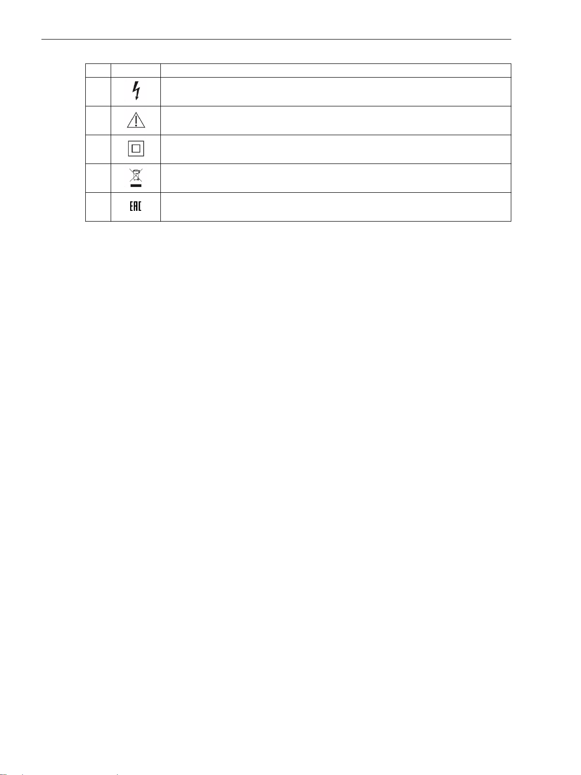
Symbol Description
No.
1 Direct current, IEC 60417-5031
2 Alternating current, IEC 60417-5032
3 Direct and alternating current, IEC 60417-5033
4 Earth (ground) terminal, IEC 60417-5017
5 Protective conductor terminal, IEC 60417-5019
SICAM, Feeder Condition Monitor, Manual 5
E50417-H8940-C580-A4, Edition 03.2019
Page 6
Preface
No. Symbol Description
6 Caution, risk of electric shock
7 Caution, risk of danger, ISO 7000-0434
8 Protective Insulation, IEC 60417-5172, Safety Class II devices
9 Guideline 2002/96/EC for electrical and electronic devices
10 Guideline for the Eurasian Market
6 SICAM, Feeder Condition Monitor, Manual
E50417-H8940-C580-A4, Edition 03.2019
Page 7

Open Source Software
The product contains, among other things, Open Source Software developed by third parties. The Open
Source Software used in the product and the license agreements concerning this software can be found in the
Readme_OSS. These Open Source Software files are protected by copyright. Your compliance with those
license conditions will entitle you to use the Open Source Software as foreseen in the relevant license. In the
event of conflicts between Siemens license conditions and the Open Source Software license conditions, the
Open Source Software conditions shall prevail with respect to the Open Source Software portions of the software. The Open Source Software is licensed royalty-free. Insofar as the applicable Open Source Software
License Conditions provide for it you can order the source code of the Open Source Software from your
Siemens sales contact - against payment of the shipping and handling charges - for a period of at least 3 years
since purchase of the Product. We are liable for the Product including the Open Source Software contained in
it pursuant to the license conditions applicable to the Product. Any liability for the Open Source Software
beyond the program flow intended for the Product is explicitly excluded. Furthermore any liability for defects
resulting from modifications to the Open Source Software by you or third parties is excluded. We do not
provide any technical support for the Product if it has been modified.
SICAM, Feeder Condition Monitor, Manual
E50417-H8940-C580-A4, Edition 03.2019
7
Page 8

8 SICAM, Feeder Condition Monitor, Manual
E50417-H8940-C580-A4, Edition 03.2019
Page 9

Table of Contents
Preface..........................................................................................................................................................3
Open Source Software..................................................................................................................................7
1 Delivery.......................................................................................................................................................11
1.1 Delivery............................................................................................................................ 12
2 Introduction................................................................................................................................................13
2.1 Overview ......................................................................................................................... 14
2.2 Environmental Protection Hints......................................................................................... 20
3 Hardware Components and Drawings........................................................................................................21
3.1 Hardware Components..................................................................................................... 22
3.2 Terminal Diagram............................................................................................................. 23
3.3 Dimensional Drawings ......................................................................................................25
4 Device Functions........................................................................................................................................ 29
4.1 Description....................................................................................................................... 30
4.1.1 Measurements and Derived Values.............................................................................. 30
4.1.2 Fault Detection............................................................................................................30
4.1.3 Fault-Reset Mechanism................................................................................................32
4.1.4 Enhanced Fault Validation and Fault-Reset Function.....................................................33
4.1.5 Trip Time DMT and IDMT .............................................................................................36
4.1.6 Ground-Fault Parameter Active Group Setting.............................................................. 37
4.1.7 Fault Indication........................................................................................................... 37
4.1.8 DO Configuration........................................................................................................ 38
4.1.9 Operating Modes.........................................................................................................38
4.1.10 Correction Factors for LoPo VT and LoPo CT (IEC 61869-10, IEC 61869-11)................... 38
4.1.11 Power-Flow Direction Reversal .................................................................................... 39
4.1.12 P,Q Sign...................................................................................................................... 39
4.1.13 3-Phase Angle Calculations.......................................................................................... 40
4.1.14 Phase-Sequence Monitoring........................................................................................ 40
4.1.15 Determination of Fault Direction..................................................................................41
4.1.16 Direction Determination of Phase Elements..................................................................42
4.1.17 Directional Ground Fault (Compensated/Resonant-Grounded) ..................................... 43
4.1.18 Directional Ground Fault (in Isolated Electrical Power Systems).................................... 43
4.1.19 Ground-Fault Direction for Solidly Grounded System.................................................... 44
4.1.20 Ground-Fault Detection with Cos φ/Sin φ Measurement............................................... 45
4.1.21 Determination of a Ground Fault with the Pulse-Location Detection Mechanism........... 46
4.1.22 Determination of the Ground-Fault Phase.................................................................... 49
4.1.23 Determination of Repeated Phase Faults with Automatic Reclosing ..............................49
SICAM, Feeder Condition Monitor, Manual 9
E50417-H8940-C580-A4, Edition 03.2019
Page 10

Table of Contents
4.1.24 Intermittent Ground Fault............................................................................................49
4.1.25 Inrush-Current Detection/Blocking ...............................................................................50
4.1.26 Primary Current Settings..............................................................................................51
4.1.27 Ground-Current Calculation......................................................................................... 51
4.1.28 Network Voltage Ratio................................................................................................. 52
4.1.29 Voltage Measurements with Sensors as per IEC 60044-7, IEC 61869-11 and with
Conventional Voltage Sensors......................................................................................52
4.1.30 Low-Voltage Measurement.......................................................................................... 53
4.1.31 Determination of Medium Voltage via Low-Voltage Measurements.............................. 53
4.1.32 Voltage Measurement via Integrated Voltage-Detecting Systems..................................54
4.1.33 Energy Measurement...................................................................................................55
4.1.34 RTC Synchronization....................................................................................................55
4.1.35 Remote Firmware Updates...........................................................................................56
4.1.36 Password Menu Access................................................................................................ 56
4.1.37 Device Alerts............................................................................................................... 57
4.1.38 Archive Logging.......................................................................................................... 58
4.1.39 Battery Freshness Mode...............................................................................................59
5 Technical Data............................................................................................................................................ 61
5.1 Device Technical Data....................................................................................................... 62
6 Type Testing............................................................................................................................................... 65
6.1 Type Testing..................................................................................................................... 66
7 Connection Diagrams................................................................................................................................. 69
7.1 Connection Diagrams........................................................................................................70
7.2 Installing the Device..........................................................................................................73
7.3 Sensor Connections.......................................................................................................... 74
7.4 Modbus Connection of SICAM FCM with RTU..................................................................... 78
A Parameterization........................................................................................................................................ 81
A.1 Parameterization...............................................................................................................82
A.2 Parameterizing the User Interface......................................................................................83
A.3 Editing the Device Settings................................................................................................91
B Modbus Registers....................................................................................................................................... 93
B.1 Modbus Registers..............................................................................................................94
B.2 Implementation of the Modbus Protocol ...........................................................................95
B.3 Bit-Type Data.................................................................................................................. 107
B.4 Register-Type Data – Holding Registers............................................................................110
B.5 Register-Type Data – Input Registers................................................................................131
B.6 Register-Type Data – Analog Input Registers.................................................................... 144
B.7 Register-Type Data - Events............................................................................................. 150
B.8 Register-Type Data – Trailing Pointers..............................................................................153
B.9 Self-Test Mode................................................................................................................ 156
Glossary.................................................................................................................................................... 171
Index.........................................................................................................................................................173
10 SICAM, Feeder Condition Monitor, Manual
E50417-H8940-C580-A4, Edition 03.2019
Page 11

1
Delivery
1.1 Delivery 12
SICAM, Feeder Condition Monitor, Manual 11
E50417-H8940-C580-A4, Edition 03.2019
Page 12

!
i
i
i
i
Delivery
1.1 Delivery
1.1
Delivery Note
Contents of Delivery
Delivery
The SICAM FCM device is delivered in a cardboard box containing the Siemens logo.
1 SICAM FCM device
•
1 document with safety instructions
•
1 ground wire
•
WARNING
Danger of explosion of the battery.
Noncompliance with the safety instructions means that death, severe injuries, or considerable material damages can occur.
Do not throw the SICAM FCM device containing a battery into a fire.
²
NOTE
SICAM FCM with 1 contained lithium metal cell (0.6 g lithium content) meets the preconditions of Special
Provision 188 of the UN Recommendations on the Transport of Dangerous Goods, 17th revised edition and
is classified according to:
ADR/RID/ADN/IMDG-Code: UN 3091 lithium metal batteries contained in equipment, 9, preconditions
•
of SP 188
ICAO-TI/IATA-DGR: UN 3091 lithium metal batteries contained in equipment, 9, preconditions of
•
Section II PI 970
NOTE
Do not transport the SICAM FCM in battery-activated mode. Before transportation, ensure that the SICAM
FCM is in Battery Freshness Mode (BFM).
12 SICAM, Feeder Condition Monitor, Manual
E50417-H8940-C580-A4, Edition 03.2019
Page 13

2
Introduction
2.1 Overview 14
2.2 Environmental Protection Hints 20
SICAM, Feeder Condition Monitor, Manual 13
E50417-H8940-C580-A4, Edition 03.2019
Page 14

Introduction
2.1 Overview
2.1
Overview
SICAM Feeder Condition Monitor (FCM) is an Intelligent Electronic Device (IED) used for detecting and indicating short circuits or ground faults with and without directional information. SICAM FCM accurately monitors, measures, and displays operational measured values and performs the condition monitoring task in a
medium-voltage distribution system. SICAM FCM is typically used in the medium-voltage and low-voltage
secondary substation that ranges from 0.4 kV to 36 kV.
SICAM FCM measures the RMS value for alternating voltage, alternating current, and power frequency.
SICAM FCM calculates the active power (P), reactive power (Q), apparent power (S), power factor (cos φ),
phase angle, energy, and other relevant values.
SICAM FCM consists of the following hardware interfaces:
3 current inputs
•
3 voltage inputs
•
1 digital input
•
2 digital outputs
•
1 RS 485 interface (Modbus RTU)
•
1 auxiliary power supply
•
[dw_fcm_block_diagram2321, 3, en_US]
Figure 2-1 SICAM FCM Block Diagram for MLFB 6MD2321-1AA00-1AA0
14 SICAM, Feeder Condition Monitor, Manual
E50417-H8940-C580-A4, Edition 03.2019
Page 15
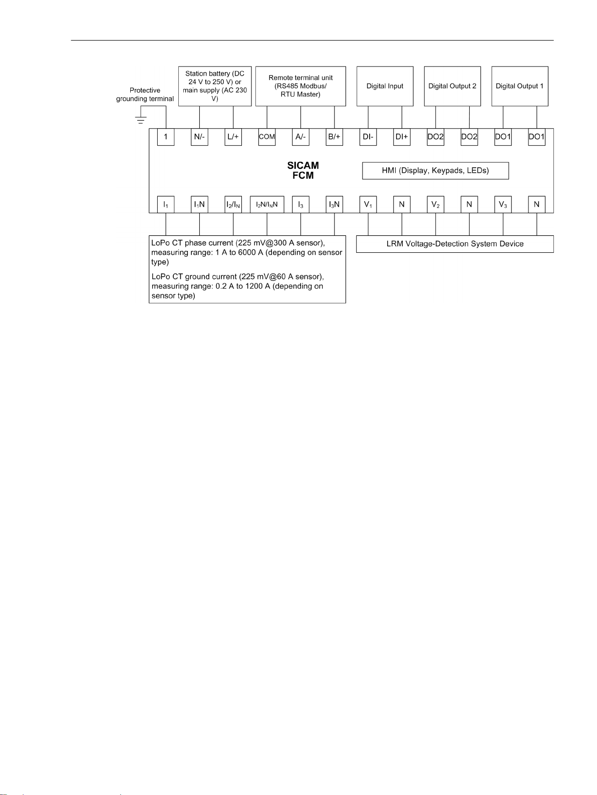
[dw_fcm_block_diagram2322, 2, en_US]
Figure 2-2 SICAM FCM Block Diagram for MLFB 6MD2322-1AA00-1AA0
Introduction
2.1 Overview
Applications
SICAM FCM is used:
As a directional and non-directional short circuit and ground-fault detector suitable for solid, isolated, and
•
compensated networks in medium-voltage and low-voltage distribution systems
As a simple power quality meter and energy measurements in various applications
•
Flush Mounting
SICAM FCM can be flush-mounted in the panel and operated inside an enclosed dry room. To mount
SICAM FCM in the panel, proceed as follows:
Cut a rectangle in the Ring-Main Unit (RMU) panel measuring 92.0 mm + 0.8 mm × 45.0 + 0.8 mm (W ×
•
H).
Carry out all the required internal wiring connections.
•
For more information about terminal diagrams, refer to 3.2 Terminal Diagram.
Flush SICAM FCM into the panel and lock it with the clamps.
•
For more information about installation, refer to 7.2 Installing the Device.
•
Device Ordering Information
Use the following ordering information to order SICAM FCM and other related accessories.
SICAM, Feeder Condition Monitor, Manual 15
E50417-H8940-C580-A4, Edition 03.2019
Page 16

Introduction
2.1 Overview
Table 2-1 SICAM FCM and Accessories Ordering Information
Description Order Number
SICAM FCM
Voltage measurements: LoPo VTs according to IEC 60044-7, IEC 61869-11,
•
conventional VT and 230 V
Current measurements: LoPo CTs according to IEC 60044-8, IEC 61869-10
•
Fault indicator with directional information and measurements of V, I, f, P,
•
Q, S, cos φ, and power-flow direction
Panel mounted
•
Dimensions in mm: 96 × 48 × 109.5
•
1 digital input
•
2 digital outputs
•
Modbus RTU
•
SICAM FCM
For voltage measurement with LRM voltage-detecting systems according
•
to IEC 61243-5
Current measurements: LoPo CTs according to IEC 60044-8, IEC 61869-10
•
Fault indicator with directional information and measurements of V, I, f, P,
•
Q, S, cos φ, and power-flow direction
Panel mounted unit with display
•
Dimensions in mm: 96 × 48 × 109.5
•
1 digital input
•
2 digital outputs
•
Modbus RTU
•
The mandatory interface cable (6MD2322-0AA80-0AB3) for linkage to the
•
Voltage-Detection System (VDS) has to be ordered separately.
Voltage-Detection System (VDS) Interface Cable
4-wire connection lead with integrated protection circuit to connect
•
SICAM FCM 6MD2322-1AA00-1AA0/CC with the LRM voltage detection
system
1 ground input
•
Length: 0.3 m
•
Mandatory accessory for each SICAM FCM 6MD2322-1AA00-1AA0 with
•
hardware revision number “CC” or higher
Adapter 1 A to low power IEC 60044-8
3 inputs, transformer ratio 225 mV@1 A
•
Accuracy class: 1
•
Thermal overload: 100 A for 1 s
•
Coil diameter: 5.8 mm
•
Adapter 5 A to low power IEC 60044-8
3 inputs, transformer ratio 225 mV@5 A
•
Accuracy class: 3
•
Thermal overload: 100 A for 1 s
•
Coil diameter: 5.8 mm
•
6MD2321-1AA00-1AA0/XX
6MD2322-1AA00-1AA0/XX
6MD2322-0AA80-0AB3
6MD2320-0AA10-1AA0
6MD2320-0AA20-1AA0
1
1
1
XX represents the hardware revision number
16 SICAM, Feeder Condition Monitor, Manual
E50417-H8940-C580-A4, Edition 03.2019
Page 17

Description Order Number
Phase current sensor – split core
Ratio: 225 mV@300 A, IEC 61869-10
•
Accuracy class: 0.5/1 extension 200 %, 5P10
•
Connection cable: 2.0 m, open end
•
Internal diameter: 65 mm
•
Phase current sensor – closed ring core
Ratio: 225 mV@700 A, IEC 60044-8
•
Accuracy class: 0.5, 5P10
•
Connection cable: 3.5 m, open end
•
Internal diameter: 82 mm
•
GOST certificate
•
Core balance current sensor – split core
Ratio: 225 mV@60 A, IEC 61869-10
•
Accuracy class: 1/3
•
Connection cable: 2.0 m
•
Window diameter: 160 mm
•
Core balance current sensor – split core
Ratio: 225 mV@60 A, IEC 60044-8
•
Accuracy class: 1
•
Connection cable: 3.5 m
•
Window diameter: 120 mm
•
GOST certificate
•
Voltage Sensor 10 kV
10 kV/√3 : 3.25/√3
•
Accuracy class: 1
•
IEC 60044-7 for symmetrical T connectors with C cone for cables: Nexans
•
(K) 440TB/ Cellpack CTS-S/Südkabel SEHDT13 and SEHDT23
Voltage factor: 1.2 V
•
Voltage factor: 1.9 VN for maximum of 8 hours
•
Voltage Sensor 10 kV
10 kV/√3 : 3.25/√3
•
Accuracy class: 1
•
IEC 60044-7 for asymmetric T connectors of nkt cables type CB-24, CC-24
•
and Raychem RSTI-58xx/RSTI-CC-58xx
Voltage factor: 1.2 V
•
Voltage factor: 1.9 VN for maximum of 8 hours
•
Voltage Sensor 10 kV
10 kV/√3 : 3.25/√3
•
Accuracy class: 0.5
•
IEC 60044-7 for asymmetric T connectors of nkt cables type CB-24
•
Voltage factor: 1.2 V
•
Voltage factor: 1.9 VN for maximum of 8 hours, GOST certificate
•
N
N
N
Introduction
2.1 Overview
6MD2320-0GA00-1AA0
6MD2320-0JA00-0BA1
6MD2320-0AF00-1AA0
6MD2320-0AF00-1AA1
6MD2320-0AA04-1AA0
6MD2320-0AA04-1AB0
6MD2320-0AA04-0AB1
SICAM, Feeder Condition Monitor, Manual 17
E50417-H8940-C580-A4, Edition 03.2019
Page 18

Introduction
2.1 Overview
Description Order Number
Voltage Sensor 20 kV
20 kV/√3 : 3.25/√3
•
Accuracy class: 0.5/1
•
IEC 61869-11 for symmetric T connectors with C cone for cables: Nexans
•
(K) 440TB/ Cellpack CTS-S/Südkabel SEHDT13 and SEHDT23
Voltage factor: 1.2 V
•
Voltage factor: 1.9 VN for maximum of 8 hours
•
Voltage Sensor 20 kV
20 kV/√3 : 3.25/√3
•
Accuracy class: 1
•
IEC 61869-11 for asymmetric T connectors of nkt cables type CB-24, CC-24
•
and Raychem RSTI-58xx/RSTI-CC-58xx
Voltage factor: 1.2 V
•
Voltage factor: 1.9 VN for maximum of 8 hours
•
Typical Ordering Combinations MLFB Number Use Case
SICAM FCM For resistive voltage
dividers, conventional VTs,
and 230 V.
Fault indicator with directional information and
measurements of V, I, f, P,
Q, S, cos φ, power-flow
direction, 2 digital outputs
SICAM FCM For voltage detecting
systems
Fault indicator with direc-
tional information and
measurements of V, I, f, P,
Q, S, cos φ, and powerflow direction, 2 digital
outputs
1 A adaptor 3 inputs @225mV low-
power signal
5 A adaptor 3 inputs @225mV low-
power signal
Phase-current
sensor
Depending on requirements
N
N
LoPo
sensors
available
6MD2321-1AA00
-1AA0/XX
6MD2322-1AA00
-1AA0/XX
6MD2320-0AA10
-1AA0
6MD2320-0AA20
-1AA0
Refer to Table 2-1 – 3 x 2 x – –
1
1
1 x 1 x 1 x 1 x –
1 x 1 x 1 x 1 x
– – – 1 x –
– – – 1 x –
Neutralpoint
treatment:
Solid/lowresistant
6MD2320-0AA07-1AA0
6MD2320-0AA07-1AB0
Neutralpoint
treatment:
Isolated/
compensated
Conventional
1 A/ 5 A
CTs available
Connecting cable
2
1 x
2
In order to set up SICAM FCM (MLFB: 6MD2322-1AA00-1AA0/CC and above) with voltage-detection system, an appropriate
connecting cable (MLFB: 6MD2322-0AA80-0AB3) must be used.
18 SICAM, Feeder Condition Monitor, Manual
E50417-H8940-C580-A4, Edition 03.2019
Page 19

Typical Ordering Combinations MLFB Number Use Case
i
i
i
i
LoPo
sensors
available
Core balance
current sensor
Voltage
sensor
Depending on requirements
For example, GOST certificate
Depending on voltage
level and form factor
NOTE
The device with MLFB number 6MD2321-1AA00-1AA0/DD and above must be loaded with firmware
V03.XX only.
The device with MLFB number 6MD2321-1AA00-1AA0/CC must be loaded with firmware V02.XX only.
Refer to Table 2-1 – –
Refer to Table 2-1 –
Neutralpoint
treatment:
Solid/lowresistant
4
(3 x)
Neutralpoint
treatment:
Isolated/
compensated
3
1 x
4
(3 x)
2.1 Overview
Conventional
1 A/ 5 A
CTs available
– –
– –
Introduction
Connecting cable
Accessories
NOTE
The device with MLFB number 6MD2322-1AA00-1AA0/CC and above must be loaded with firmware V03.XX
only.
The device with MLFB number 6MD2322-1AA00-1AA0/BB must be loaded with firmware V02.XX only.
You can download the current version of the SICAM FCM manual from Siemens Powerquality.
3
The ground current can also be calculated in isolated/compensated electrical power systems. Consider information regarding accuracy.
4
Optional for measuring purpose or for directional information
SICAM, Feeder Condition Monitor, Manual 19
E50417-H8940-C580-A4, Edition 03.2019
Page 20

i
i
i
i
Introduction
2.2 Environmental Protection Hints
2.2
Disposal of Old Equipment and Batteries (Applicable only for European Union and Countries with a Recycling
System)
Disposal of Mobile Storage Devices (e.g. USB Sticks and Memory Cards)
Environmental Protection Hints
The disposal of our products and possible recycling of their components after decommissioning has to be
carried out by an accredited recycling company, or the products/components must be taken to applicable
collection points. Such disposal activities must comply with all local laws, guidelines and environmental specifications of the country in which the disposal is done. For the European Union the sustainable disposal of electronic scrap is defined in the respective regulation for "waste electrical and electronic equipment" (WEEE).
The crossed-out wheelie bin on the products, packaging and/or accompanying documents means
that used electrical and electronic products and batteries must not be mixed with normal household waste.
According to national legislation, penalties may be charged for incorrect disposal of such
waste.
By disposing of these products correctly you will help to save valuable resources and prevent any potential
negative effects on human health and the environment.
NOTE
Our products and batteries must not be disposed of as household waste. For disposing batteries it is necessary to observe the local national/international directives.
When disposing of/transferring mobile storage devices, using the format or delete functions only changes the
file management information and does not completely delete the data from your mobile storage device. When
disposing of or transferring a mobile storage device, Siemens strongly recommends physically destroying it or
completely deleting data from the mobile storage device by using a commercially available computer data
erasing software.
REACH/RoHS Declaration
You can find our current REACH/RoHS declarations at:
https://www.siemens.com/global/en/home/products/energy/ecotransparency/ecotransparency-downloads.html
NOTE
You can find more information about activities and programs to protect the climate at the EcoTransparency
website:
https://www.siemens.com/global/en/home/products/energy/ecotransparency.html
20 SICAM, Feeder Condition Monitor, Manual
E50417-H8940-C580-A4, Edition 03.2019
Page 21

3
Hardware Components and Drawings
3.1 Hardware Components 22
3.2 Terminal Diagram 23
3.3 Dimensional Drawings 25
SICAM, Feeder Condition Monitor, Manual 21
E50417-H8940-C580-A4, Edition 03.2019
Page 22

Hardware Components and Drawings
3.1 Hardware Components
3.1
Hardware Components
In this manual, SICAM FCM is also referred as device.
Microcontroller
•
The device uses a low-power ARM MCU which includes high-precision 16-bit ADCs.
Battery
•
The device contains a battery with 3.6 V and a capacity of 1.2 Ah.
LCD
•
LCD is used to view real-time values, events, archives, and device parameters.
Keypads
•
The 4 navigation keys are used to navigate through the device menu and to select the desired parameters. The functions of the navigation keys are specific to different menu sections.
LEDs
•
The device consists of 3 LEDs which indicate the status of the process.
– FAULT (Red)
Indicates when any distribution-system fault is detected
– COM (Yellow)
Indicates that the communication is active between Modbus master and the SICAM FCM
– RUN (Green)
Indicates the healthy condition of the device and operating on the auxiliary voltage
Digital Input
•
The device consists of 1 digital input for resetting the fault indication.
Digital Output
•
The device consists of 2 digital outputs for indicating fault conditions.
[dw_sfcmhwbd, 1, en_US]
Figure 3-1 SICAM FCM Hardware Block Diagram
22 SICAM, Feeder Condition Monitor, Manual
E50417-H8940-C580-A4, Edition 03.2019
Page 23
Hardware Components and Drawings
3.2 Terminal Diagram
3.2
Terminal Diagram
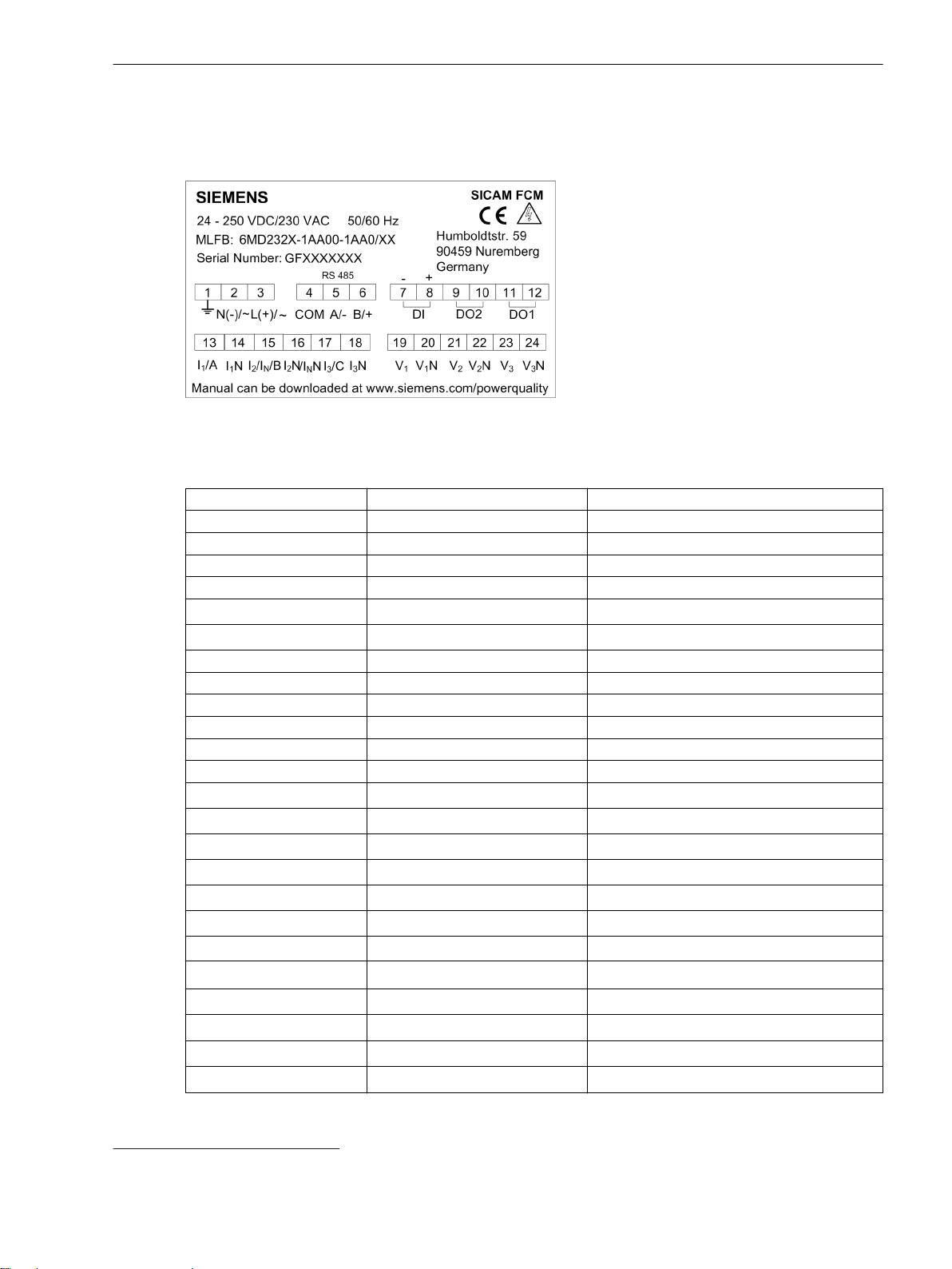
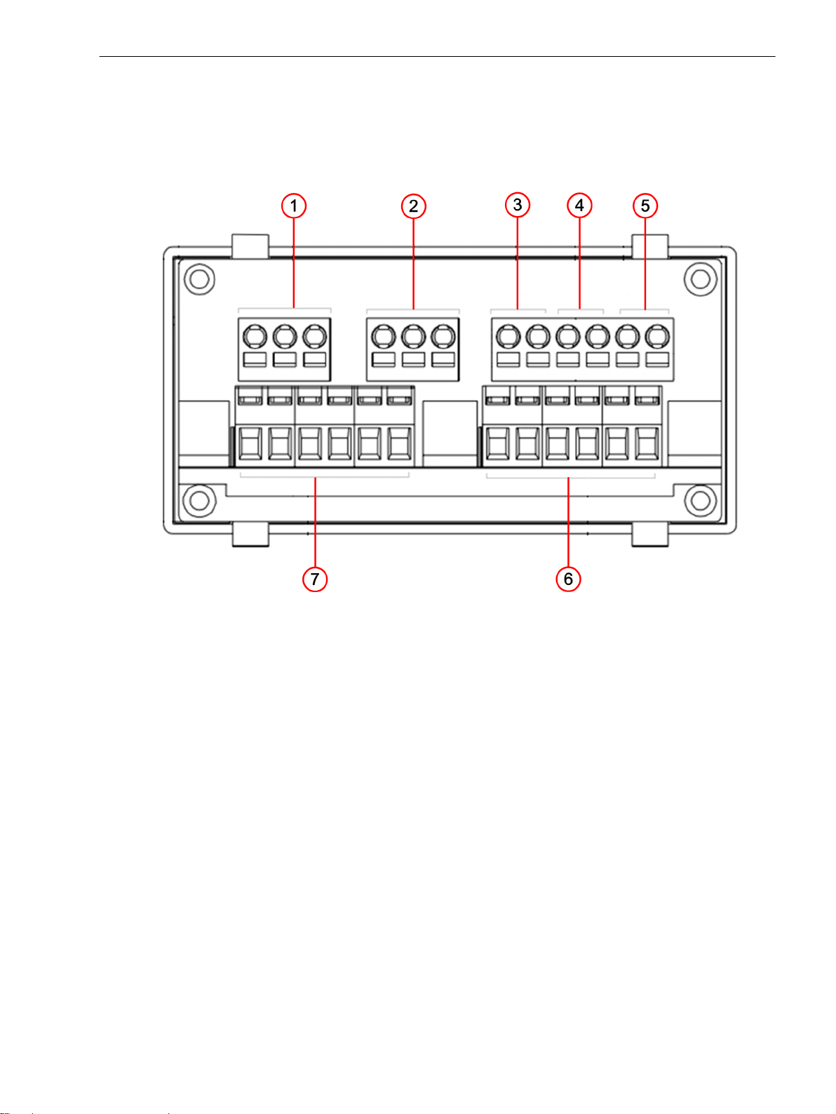
The terminal diagram is located on top of the housing and displays the terminal numbers and terminals.
[dw_sfcmtrml, 2, en_US]
Figure 3-2 Terminal Diagram
Table 3-1 Terminal Specifications
Terminal Number Terminal Name Description
(1) 1 Functional ground
(2) N(-)/~ Auxiliary voltage
(3) L(+)/~ Auxiliary voltage
(4) COM Modbus - Common
(5) A/- Modbus - T
(6) B/+ Modbus - R
(7) DI1(-) Digital input (-)
(8) DI1(+) Digital input (+)
(9) DO2 Digital output 2
(10) DO2 Digital output 2
(11) DO1 Digital output 1
(12) DO1 Digital output 1
(13) I1/A Phase current I
(14) I1N Neutral
(15) I2/IN/B Phase current I2 or ground current I
(16) I2/INN Neutral
(17) I3/C Phase current I
(18) I3N Neutral
(19) V
(20)
(21) V
(22)
(23) V
(24)
1
V1N
2
V2N
3
V3N
5
5
5
Voltage input V
Neutral
Voltage input V
Neutral
Voltage input V
Neutral
x
x
1
N
3
1
2
3
5
V1N, V2N, V3N are internally shorted
SICAM, Feeder Condition Monitor, Manual 23
E50417-H8940-C580-A4, Edition 03.2019
Page 24

Hardware Components and Drawings
3.2 Terminal Diagram
Terminal Connections
You can connect the device terminals with a wire of cross-section ranging from 0.75 mm2 to 2.5 mm2. Use the
following options to connect the terminals:
Spring-cage connection
•
Spring-cage connection is used to connect the upper row of terminals. From terminal 1 to terminal 12.
Screw connection
•
Screw connection is used to connect the bottom row of terminals. From terminal 13 to terminal 24.
The following tables show the technical details of the different connection methods.
Table 3-2 Spring-Cage Connection
Connection Elements Specifications
Connection method Spring cage
Conductor size (solid)
Conductor size (stranded)
Stripping length 8.0 mm
AWG (max.) 12.0
AWG (min.) 24.0
4.0 mm
2.5 mm
2
2
Table 3-3 Screw Connection
Connection Elements Specifications
Connection method Screw connection
Conductor size (solid)
Conductor size (stranded)
1.0 mm
1.0 mm
2
2
Stripping length 8.0 mm
AWG (max.) 16.0
AWG (min.) 26.0
Torque 0.5 Nm
Screwdriver size 3/32 inch or 2.5 mm
24 SICAM, Feeder Condition Monitor, Manual
E50417-H8940-C580-A4, Edition 03.2019
Page 25
Hardware Components and Drawings
3.3 Dimensional Drawings
3.3
Rear View
Dimensional Drawings
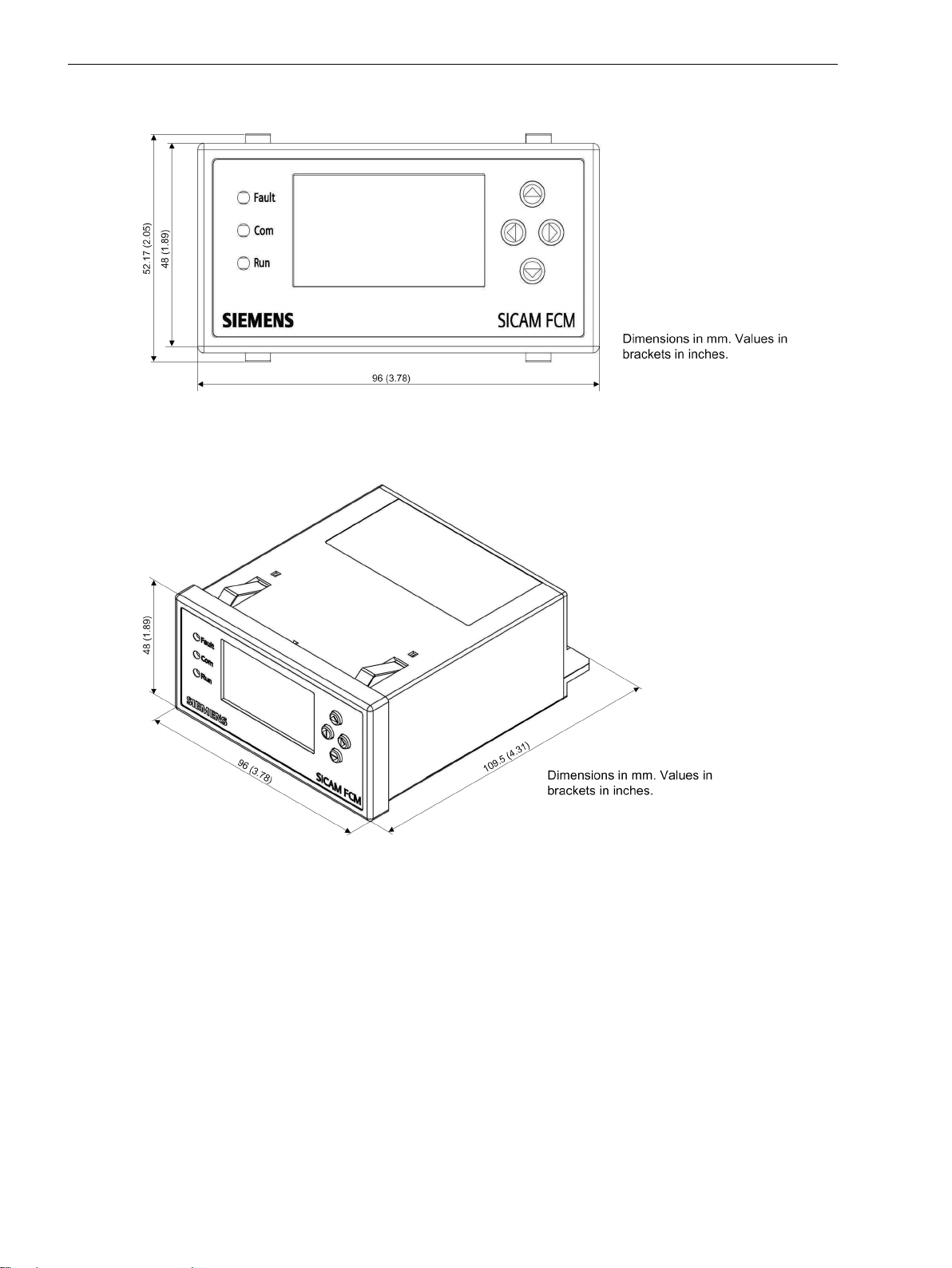
This chapter shows the dimensional drawings and different views of the device.
[le_sfcmrearview, 1, --_--]
Figure 3-3
(1) Power supply
(2) Modbus
(3) Digital input
(4) Digital output 2
(5) Digital output 1
(6) Voltage input
(7) Current input
Rear View with Terminals
SICAM, Feeder Condition Monitor, Manual 25
E50417-H8940-C580-A4, Edition 03.2019
Page 26
Hardware Components and Drawings
3.3 Dimensional Drawings
Front View
[dw_fcm_front, 1, en_US]
Figure 3-4 Front View
Isometric View
[dw_fcm_iso_view, 1, en_US]
Figure 3-5 Isometric View
26 SICAM, Feeder Condition Monitor, Manual
E50417-H8940-C580-A4, Edition 03.2019
Page 27
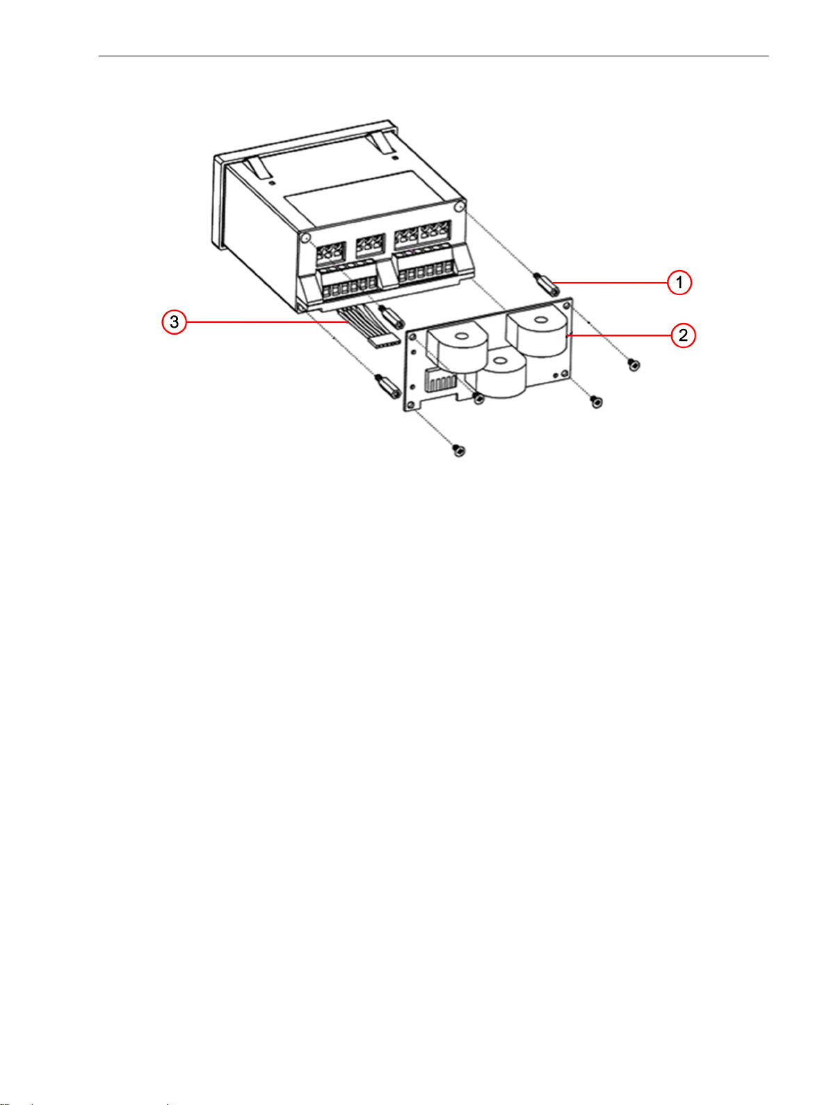
1 A/5 A Adaptor Drawing
Hardware Components and Drawings
3.3 Dimensional Drawings
[le_sfcm1aadap-231015, 1, --_--]
Figure 3-6 1 A/5 A Adaptor
(1) Threaded stud
(2) CT adaptor PCB
(3) Cable assembly
SICAM, Feeder Condition Monitor, Manual 27
E50417-H8940-C580-A4, Edition 03.2019
Page 28
Hardware Components and Drawings
3.3 Dimensional Drawings
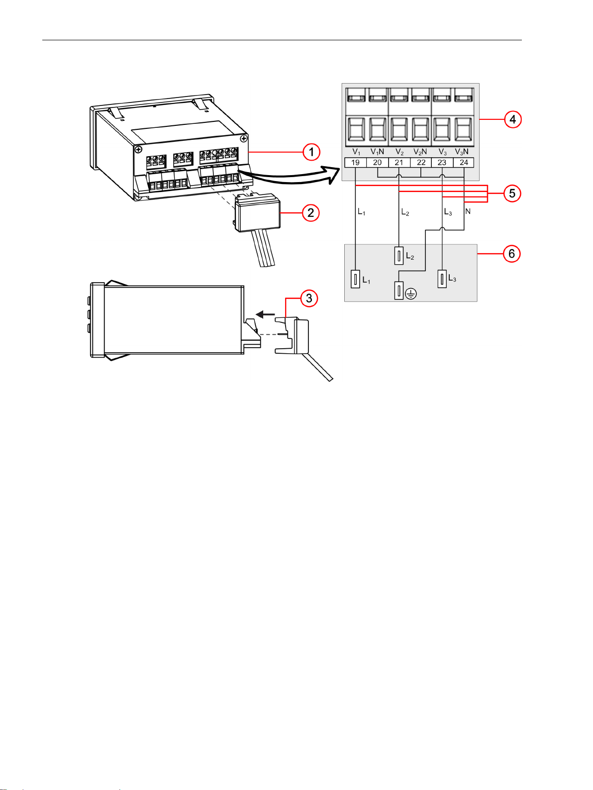
SICAM FCM with Connecting Cable (only for 6MD2322-1AA00-1AA0)
[le_sfcm-capconncbl, 2, --_--]
Figure 3-7
Connecting Cable of SICAM FCM
(1) SICAM FCM
(2) Connecting cable (6MD2322-0AA80-0AB3); necessary for 6MD2322-1AA00-1AA0
(3) Orientation of connecting cable to SICAM FCM voltage-input terminals
(4) SICAM FCM voltage-input terminals
(5) Connecting cable (L1, L2, L3, ground)
(6) Voltage-detection system
28 SICAM, Feeder Condition Monitor, Manual
E50417-H8940-C580-A4, Edition 03.2019
Page 29

4
Device Functions
4.1 Description 30
SICAM, Feeder Condition Monitor, Manual 29
E50417-H8940-C580-A4, Edition 03.2019
Page 30

i
i
Device Functions
4.1 Description
4.1
4.1.1
4.1.2
Description
Measurements and Derived Values
The device measures and calculates the values which are displayed on the HMI/Modbus. The following table
shows the measured values and derived values of the device when it is connected to the medium-voltage
system and low-voltage system.
Table 4-1 Measurements and Derived Values
Measurements Derived Values
Phase I1, phase I2, phase I
Phase I1, ground IN, phase I
Phase V1, V2, V
Frequency 50 Hz/60 Hz –
– Active power, reactive power, and apparent power
– cos φ (power factor)
– Phase angle
– Active import energy, active export energy, reactive import energy, and
3
3
3
Fault Detection
IN and 2nd harmonic of the phase current
I2 and 2nd harmonic of the phase current
Phase-to-phase voltages (V12, V23, V31)
reactive export energy
The device determines the fault based on the following criteria:
Overcurrent detection for phase currents (I>, I>>) and ground current (IN>)
•
Ground-current and neutral-point displacement voltage (IN> and VNG>) for resonant-grounded/isolated
•
system
where VNG is an internally calculated value.
You can configure the individual time-delay setting for phase current and ground currents.
Table 4-2
tI> Timer for the low-set current threshold I>
tI>> Timer for the high-set current threshold I>>
tIN> Timer for the ground-current threshold IN>
tVNG> Timer for neutral-point displacement voltage VNG>
NOTE
For fault detection, the highest values of one of the timers are considered.
The device uses the Definite Minimum Time (DMT) or Inverse Definite Minimum Time (IDMT) characteristics
for detecting the fault. It identifies the type of the fault and also determines the direction.
The following logic diagram shows the fault indication.
Timer Configuration
30 SICAM, Feeder Condition Monitor, Manual
E50417-H8940-C580-A4, Edition 03.2019
Page 31

i
i
i
i
Device Functions
4.1 Description
[lo_sfcm_phase_fault_indication, 2, en_US]
Figure 4-1
[lo_ground_fault_reset, 3, en_US]
Figure 4-2 Logic Diagram for Ground-Fault Detection
For isolated ground:
IN (Watt-metric) = IN ⋅ sin φ
For resonant ground:
IN (Watt-metric) = IN ⋅ cos φ
For more information about ground-fault detection by watt-metric method, refer to chapter 4.1.20 Ground-
Fault Detection with Cos φ/Sin φ Measurement
NOTE
For solid ground or if I
Logic Diagram for Phase-Fault Indication
is set to 0, I
dir
is disabled and only IN is used for detecting the ground fault.
dir
NOTE
For solid ground or if VNG is set to 0, VNG is disabled and only IN/IN (Watt-metric) is used for detecting the
ground fault.
SICAM, Feeder Condition Monitor, Manual 31
E50417-H8940-C580-A4, Edition 03.2019
Page 32

i
i
Device Functions
4.1 Description
NOTE
For isolated/compensated systems in case of 2-phase-to-ground and 3-phase-to-ground faults, whenever a
ground fault and phase fault occur at a same time, SICAM FCM indicates phase fault as a priority event on
HMI/Modbus.
For more information about direction determination, refer to 4.1.15 Determination of Fault Direction,
4.1.16 Direction Determination of Phase Elements, 4.1.17 Directional Ground Fault (Compensated/Resonant-
Grounded) , and 4.1.18 Directional Ground Fault (in Isolated Electrical Power Systems).
For more information about fault-detection parameters, see Table A-2 for the Fault Parameters > Phase-Fault
Detection menu and Table A-3 for the Fault Parameters > Ground-Fault Detection menu.
4.1.3
Fault-Reset Mechanism
The fault status of the device can be reset through anyone of the following mechanisms:
Auto reset as per user-defined time setting
•
Digital input (DC 24 V to DC 60 V)
•
User interface through keypad (Reset)
•
RS485/Modbus interface
•
The following logic diagram shows the fault-reset mechanism.
[lo_sfcm_faultresetmech, 2, en_US]
Figure 4-3
(1) Binary contact 1, indication on HMI and Modbus, event logs
(2) Binary contact 2, indication on HMI and Modbus, event logs
(3) Binary contact 1 and Binary contact 2, indication on HMI and Modbus, event logs
32 SICAM, Feeder Condition Monitor, Manual
Logic Diagram for Fault Indication and Fault Reset Mechanism
E50417-H8940-C580-A4, Edition 03.2019
Page 33

Device Functions
4.1 Description
4.1.4
Enhanced Fault Validation and Fault-Reset Function
The enhanced fault validation provides an additional functionality by detecting the absence of voltage or
current and enables a delay of the fault indication and fault reset.
The fault can be detected and reset by additionally configuring the following timers:
Timer Description
T1 Monitoring period for fault validation
T2 Absence of voltage and current monitoring time
T3 Auto reset time after resumption of voltage or current
When the system phase current exceeds the set current thresholds (I>, low-set or I>>, high-set) and persists
for the defined time (tI>), the device starts monitoring the pickup time (T1). When the fault is isolated, the
system voltage/current drops. When this condition is reached, the device monitors the absence of voltage for a
time T2 for the drop in voltage or current as long as it reaches values below 6 kV (phase-to-ground) or 5 A
respectively. The fault is indicated if the absence of voltage or current persists until the timer T2 elapses
(T2<T1).
For the ground fault, configure the threshold for the neutral-point displacement voltage (VNG>) and the
ground current (IN>). If the threshold exceeds the setting and the fault persists for the times tIN> and tVNG>,
the device indicates the ground fault based on the timers T1 and T2.
If the timer T3 is configured, then the auto reset of the fault indication occurs after the resumption of voltage
or currents. The device monitors if the voltages or currents of the system increase for this time period T3
above 6 kV or 5 A respectively. After elapse of the set time, the device resets the fault indication.
The following logic diagrams illustrates the fault-detection initiation and fault reset.
[lo_sfcmfaultdetect-reset, 2, en_US]
Figure 4-4
SICAM, Feeder Condition Monitor, Manual 33
E50417-H8940-C580-A4, Edition 03.2019
Logic Diagram for Fault-Detection Initiation and Fault Reset
Page 34

i
i
i
i
Device Functions
4.1 Description
[lo_fault_det_ini_and_reset, 3, en_US]
Figure 4-5
For isolated ground:
IN (Watt-metric) = IN ⋅ sin φ
For resonant ground:
IN (Watt-metric) = IN ⋅ cos φ
For more information about ground-fault detection by watt-metric method, refer to chapter 4.1.20 Ground-
Fault Detection with Cos φ/Sin φ Measurement
NOTE
For solid ground or if I
NOTE
For solid ground or if VN> is set to 0, VNG is disabled and only IN/IN (Watt-metric) is used for detecting the
ground fault.
The following logic diagram illustrates the fault indication and fault reset.
Logic Diagram for Fault-Detection Initiation and Fault Reset
is set to 0, I
dir
is disabled and only IN is used for detecting the ground fault.
dir
34 SICAM, Feeder Condition Monitor, Manual
E50417-H8940-C580-A4, Edition 03.2019
Page 35

Device Functions
4.1 Description
[lo_sfcm_fltindrst, 2, en_US]
Figure 4-6
Logic Diagram for Fault Indication and Fault Reset
The following figure describes the timer-based fault-indication operation.
[lo_medvolsup, 2, en_US]
Figure 4-7 Timer-Based Fault Indication
SICAM, Feeder Condition Monitor, Manual 35
E50417-H8940-C580-A4, Edition 03.2019
Page 36

i
i
Device Functions
4.1 Description
NOTE
If any of the timers T1, T2, and T3 is set to 0, the other 2 timers are disabled. For example, if T1=0, T2 and
T3 are disabled.
4.1.5
Definite Minimum Time (DMT)
Trip Time DMT and IDMT
SICAM FCM supports both the DMT and IDMT function.
DMT is applicable for both the phase fault and the ground fault.
The 3 DMT settings are I>, I>>, IN>. Each setting consists of the independent trip-time delays tI>, tI>>, and tIN>.
The user-defined DMT setting is used to configure various current thresholds for the entire dynamic primary
current range.
If the current in the system exceeds the set threshold and persists for the set time specified, the device indi-
cates a fault. The device provides an option to set for 2 current thresholds and 2 time delay thresholds.
The following table illustrates the parameter settings and the values.
Table 4-3 Reference
Parameter Attribute Value
I> Setting 50 A to 2500 A
tI> Delay setting 40 ms to 60 s
I>> Setting 50 A to 2500 A
tI>> Delay setting 40 ms to 60 s
IN> Setting 0.4 A to 2000 A
tIN> Delay setting 40 ms to 60 s
Table 4-4 Operate Level
Parameter Attribute Value
I> Operate level 110 % of I> ±5 %
I>> Operate level 110 % of I>> ±5 %
Table 4-5 Operate Time
Parameter Attribute Value
tI> Operate time 40 ms ±25 ms
tI>> Operate time 40 ms ±25 ms
Inverse Definite Minimum Time (IDMT)
IDMT characteristics are defined as Inverse because the trip time is inversely proportional to the fault current
being measured.
In SICAM FCM, the IDMT function supports the Normal Inverse (NI) characteristics. The ANSI codes supported
by the IDMT function are non-directional (51) and directional (67) for overcurrent indication.
IDMT function is applicable only for the phase currents I1, I2, and I3.
The following table illustrates the parameter settings and the values.
Table 4-6
Parameter Attribute Value
I> Setting 50 A to 2500 A
Reference
36 SICAM, Feeder Condition Monitor, Manual
E50417-H8940-C580-A4, Edition 03.2019
Page 37

i
i
i
i
Device Functions
4.1 Description
Table 4-7 Operate Level
Parameter Attribute Value
I> Operate level 110 % of I> ±5 %
Table 4-8 Operate Time
Parameter Attribute Value
Operate time char = IEC-NI ±5 % absolute or ±40 ms
Time multiplier setting (k) 0.09 –
NOTE
The IDMT function is not applicable for the ground fault IN.
If tI> is set to zero, the NI trip time curve according to the IEC characteristics is calculated based on the
following formula.
I
is the fault current. I
fault
The fixed value of k is 0.09.
is the setting value of the pickup current.
set
4.1.6
4.1.7
NOTE
For setting the IDMT characteristics curves, set tI> = 0.
Ground-Fault Parameter Active Group Setting
The device provides 2 groups of settings (Group 1 and Group 2) for the Neutral-point treatment parameter (solid, resonant, isolated) and Ground-fault parameters (IN>, tIN>, VNG>, tVNG>, and I
You can select the active group and its group parameter from HMI and Modbus, by holding register (address
42) or by turning ON the coil 12. When the device is indicating a fault, you cannot change the active group
and its parameters.
At any time, only one selected group of settings is active. These parameters are used for detecting the ground
fault.
For more information about the active-group switching coil, refer to Table B-10.
For more information about the active group, refer to Active Group, Page 121.
).
dir
Fault Indication
When the device detects a fault, the following components are activated:
LED
•
The red LED is turned on and indicates a fault.
LCD
•
The LCD displays fault current values with the fault type.
Modbus
•
The device sends the fault current, fault type, and additional fault information to the RTU.
If a fault is detected, the red LED flashes every 1 s if the device is not powered through an auxiliary supply.
SICAM, Feeder Condition Monitor, Manual 37
E50417-H8940-C580-A4, Edition 03.2019
Page 38

i
i
Device Functions
4.1 Description
NOTE
For the temperatures below -20 °C, the LCD display can take up to 2 min to start or display the data.
4.1.8
4.1.9
DO Configuration
The digital output (DO) is configured to indicate either the fault direction or the device-health
status by using the DO configuration parameter.
If the DOs are configured to indicate the fault direction:
DO1 operates to indicate a forward fault direction and DO2 operates to indicate a reverse fault direction.
•
Operation of both DOs indicates that the fault direction could not be determined.
•
If the DOs are configured to indicate the device-health status:
DO1 operates to indicate an unhealthy device (DO2 is deactivated).
•
If both DOs do not operate, this is an indication that the device is healthy.
•
The DO configuration can only be switched if SICAM FCM does not indicate any faults.
For more information about the DO configuration parameter, refer to DO Configuration, Page 123.
Operating Modes
The device goes to the sleep mode when disconnected from an auxiliary supply. In this mode, the communication with the RTU is not available. In the sleep mode, you can press any of the keys to view the events.
The device enters the deep sleep mode after 8 hours in the sleep mode and requires an auxiliary supply to
recover from this mode.
4.1.10
Correction Factors for LoPo VT and LoPo CT (IEC 61869-10, IEC 61869-11)
IEC 61869-10 and IEC 61869-11 allow to adjust the magnitudes and phases of current and voltage sensors. If
any inaccuracies are stable within the measuring range, then the overall accuracy of sensors is improved to
higher level.
Sensors which specify individual correction factors on their labels and in routine tests can be configured
•
in SICAM FCM to improve system accuracy.
Sensors which are used in combination with SICAM FCM and do not have correction factors, disable the
•
respective correction factors. In this way, the device works with secondary values as measured without
any influence on magnitudes and phase angles.
The correction factors are expressed in terms of magnitude and angle offset per phase of voltage/current. By
enabling the Correction Factor parameter via HMI or Modbus, then the device applies these correction
factors to improve the measuring accuracy of the sensor.
The correction factor works as per the following logic:
The measured phase-to-ground voltages and measured phase currents/ground currents are multiplied by
•
the respective voltage and current magnitude factor.
The measured phase-to-ground voltage and phase currents/ground current angles are added for positive
•
angle offset or subtracted for negative angle offset.
The correction factor is applied on all measured values and reflects on all derived values.
•
If Correction Factor parameter (holding register address 79) is set to 0 (disabled), then the correction
factors with the holding addresses 80 to 91 are set to 0 and not applied in voltage/current measurements.
38 SICAM, Feeder Condition Monitor, Manual
E50417-H8940-C580-A4, Edition 03.2019
Page 39

i
i
Device Functions
4.1 Description
If Correction Factor parameter (holding register address 79) is set to 1 (enabled), then the correction
factors with the holding addresses 80 to 91 are set to the default values. For more information about holding
registers, refer to Table B-5.
NOTE
The voltage magnitude and voltage angle offset are applicable only for the 3.25/√3 LoPo VT.
The current magnitude and current angle offset are applicable only for the LoPo current sensor.
4.1.11
Power-Flow Direction Reversal for Solidly-Grounded System
Power-Flow Direction Reversal
The following power-flow direction parameters define the polarity of the CT/LoPo sensor for I1, I2, and I3 measurements:
I1 power-flow direction
•
I2/IN power-flow direction
•
I3 power-flow direction
•
If the CT/LoPo sensor is connected in the opposite direction, the current measured using the CT/LoPo sensor
has an additional phase shift of 180°. The power-flow direction parameters are used to compensate the additional phase shift.
If the power-flow direction parameters are set to reversed, the power-flow direction is reversed by adding
180° to the respective measured phase-current angle.
If the power-flow direction parameters are set to not reversed, it restores the power-flow direction to the
original direction.
For more information about power-flow direction parameters, refer to I1 Power-Flow Direction, Page 124.
The following power-flow direction reversal parameters affect the respective power-flow direction, fault direction, and power:
I
•
1
I
•
2
I
•
3
They also affect the IN angle, IN power-flow direction, and IN> fault direction. The corrected angles for I1, I2,
and I3 are displayed in the Modbus input register.
If the power-flow direction parameters are set to reversed, the fault direction is shifted by 180°.
Power-Flow Direction Reversal for Resonant/Isolated Grounded System
The power-flow direction reversal for IN affects the IN power-flow direction, IN fault direction, and watt-metric
ground current. The original IN angle before correction is displayed in the Modbus input register and is used
for deriving the I2 angle.
The power-flow direction reversal for I1 and I3 affects the respective power-flow direction, fault direction, and
power. The corrected angles for I1 and I3 are displayed in the Modbus input register.
If the power-flow direction parameters are set to not reversed, the fault direction is shifted by 180°.
4.1.12
SICAM, Feeder Condition Monitor, Manual 39
E50417-H8940-C580-A4, Edition 03.2019
P,Q Sign
The P,Q sign parameter is used to reverse the sign of active power (P) and reactive power (Q) for all phases.
The P,Q sign parameter cannot be configured for individual phases.
Page 40

Device Functions
4.1 Description
If the P,Q sign parameter value is set to not reversed, the sign of active power (P) and reactive power
(Q) for all phases indicates the original active power (P) and reactive power (Q). If the P,Q sign parameter
value is set to reversed, the signs of active power (P) and reactive power (Q) for all phases get reversed. The
P,Q sign parameter is independent of the power-flow direction parameter. The P,Q sign parameter
affects the total active power (P) and reactive power (Q). The P,Q sign parameter does not affect the
power-flow direction, fault direction, current angle, and power factor for all phases. It also does not affect the
watt-metric ground current.
For more information about the P,Q sign parameter, refer to P,Q Sign, Page 125.
4.1.13
3-Phase Angle Calculations
A phase sequence defines the sequential timing in which each phase-to-ground voltage phasor lags each
phase-to-ground voltage phasor in the counter-clockwise direction.
Figure 4-8 shows the 3-phase sequence. The sequence shown below implies that V12 leads V23 by 120° and
V23 leads V31 by 120°. In addition, V1N leads V2N by 120° and V2N leads V3N by 120°. It is mandatory to
establish the balanced phase sequence before any calculations. In the device, V1N is considered as a reference
phasor at 0°. This phase sequence is needed to relate the calculated phasor angles with reference to the
phasor V1N.
[dw_sfcm3phangcalc, 1, en_US]
Figure 4-8 3-Phase Angle Calculations
In a standard balanced system, all phase-to-phase voltages are phase-to-neutral voltages multiplied by √3 and
lead the phase-to-neutral voltage phasors by 30°. For example, in a standard 4-wire, 3-phase wye system with
phase-to-neutral voltages of 120 V and V1N selected as the reference phasor, then phase-to-phase voltages
are as follows: V12 = 208∠ 30°; V23 = 208∠ 270°; V31 = 208∠ 150°.
4.1.14
40 SICAM, Feeder Condition Monitor, Manual
Phase-Sequence Monitoring
The phase sequence of the measured phase-to-ground voltages is checked by monitoring the angle difference
between phase-to-ground and phase-to-phase voltages.
SICAM FCM monitors the phase sequence of voltage signals from voltage sensors and displays it on the HMI/
Modbus. The phase-sequence monitoring algorithm uses measured phase-to-ground voltage and phase-tophase voltage angles in balanced condition. For monitoring the phase sequence, the threshold voltage is at
least 50 % of primary voltage.
E50417-H8940-C580-A4, Edition 03.2019
Page 41

i
i
Device Functions
4.1 Description
If the phase sequence is clockwise, then it is denoted as ABC. Similarly if the phase sequence is counter-clockwise, then it is denoted as ACB. The monitored phase sequence is also displayed as 2 discrete inputs in the
Modbus register.
The following phasor diagram shows the clockwise and counter-clockwise phase sequences:
[dw_sfcm-phasesequence, 1, en_US]
Figure 4-9 Clockwise and Counter-Clockwise Phase Sequences
4.1.15
In the HMI, the status of the phase sequence is shown as PH SEQ: ABC or PH SEQ: ACB or ---, if the phase
sequence cannot be determined.
If the phase sequence is ABC, then the discrete input (33) of the Modbus register is set to 1.
If the phase sequence is ACB, then the discrete input (34) of the Modbus register is set to 1.
If the phase sequence is not detected, then the discrete inputs (33, 34) of the Modbus registers are set to 0.
If the phase-to-ground voltage is below the threshold voltage, then the phase sequence is displayed as --- on
the HMI and the Modbus register is set to 0.
If there are any device alerts and a fault is detected in the system, then the phase sequence is displayed as ---
on the HMI and the Modbus register is set to 0.
NOTE
Protection functions implemented in SICAM FCM are designed for clockwise phase sequence only.
Determination of Fault Direction
The fault direction for the phase faults is determined by calculating the phase angles between the fault
current and the corresponding phase-to-phase voltages.
Pickup
1 I
2 – – I
3 – – – – I
N – – – – – – –
1, N I
2, N – – I
3, N – – – – I
Measuring Element
1 2 3 N
1
1
V2 - V
V2 - V
– – – – – –
3
2
– – – – I
3
2
V3 - V
V3 - V
1
1
– – – –
3
V1 - V
2
– – I
3
V1 - V
2
– –
N
N
I
N
6
V
NG
6
V
NG
6
V
NG
6
V
NG
6
VNG = V1 + V2 + V3 (derived value)
SICAM, Feeder Condition Monitor, Manual 41
E50417-H8940-C580-A4, Edition 03.2019
Page 42

i
i
Device Functions
4.1 Description
Pickup Measuring Element
1, 2 I
2, 3 – – I
1, 3 I
1, 2, N I
2, 3, N – – I
1, 3, N I
1, 2, 3 I
1, 2, 3, N I
1 2 3 N
1
1
1
1
1
1
V2 - V
V2 - V
V2 - V
V2 - V
V2 - V
V2 - V
I
3
2
2
– – I
3
I
3
2
2
– – I
3
I
3
2
I
3
2
V3 - V
V3 - V
V3 - V
V3 - V
V3 - V
V3 - V
1
1
1
1
1
1
– – – –
I
3
3
V1 - V
V1 - V
2
2
– – I
I
3
3
I
3
I
3
V1 - V
V1 - V
V1 - V
V1 - V
2
2
2
2
– –
– –
N
I
N
I
N
– –
I
N
6
V
NG
6
V
NG
6
V
NG
6
V
NG
4.1.16
Direction Determination of Phase Elements
In the device, the directional overcurrent element operates for any faults either in forward direction or in
reverse direction.
The directional determination of phase elements works in the quadrature connection to prevent the loss of
polarizing quantity for close-in phase faults. Each current element has a direction by a voltage derived from
the other 2 phases. This connection introduces a 90° phase jump (current leading voltage) between reference
voltages and operating quantities (currents). A fault is determined to be in the selected direction if its phase
relationship lies within a quadrant of ± 85° on either side of the characteristic angle. It is hard-coded as +45°.
[dw_sfcm-dirdetphaelm, 1, en_US]
Figure 4-10 Direction Determination of Phase Elements
NOTE
The undetermined area for the device MLFB 6MD2321-1AA00-1AA0 is 10° and the respective angles
change accordingly.
The undetermined area for the device MLFB 6MD2322-1AA00-1AA0 is 20° and the respective angles
change accordingly.
42 SICAM, Feeder Condition Monitor, Manual
E50417-H8940-C580-A4, Edition 03.2019
Page 43

i
i
Device Functions
4.1 Description
4.1.17
Directional Ground Fault (Compensated/Resonant-Grounded)
In the compensated/resonant-grounded system, the Petersen coil is configured to match the capacitive
charging currents, such that when a ground fault occurs, a negligible fault current flows. The characteristic
angle is set to 0°. A boundary of +90° is used to detect the direction of the resistive component within residual
currents.
With the cos φ method, the watt-metric residual current is calculated in case of a fault. This method of determining the ground-fault detection is implemented in the watt-metric method. For more information about the
watt-metric method, refer to 4.1.20 Ground-Fault Detection with Cos φ/Sin φ Measurement.
In the vector method, the ground-fault detection occurs if the total current IN> is exceeded.
The device calculates the active power of the zero sequence (P0) and if the value is falling in the 1st and the
4th quadrant, then the direction is forward. If the active power of the zero sequence (P0) is falling in the 2nd
and 3rd quadrant, then the direction is shown as reverse.
For more information about directional ground-fault parameters (compensated/resonant-grounded), see
Table A-3 and refer to the Fault Parameter > Ground-Fault Detection > Neutral-point Treatment menu.
4.1.18
[dw_sfcm-grndflt-comp-res, 1, en_US]
Figure 4-11 Directional Ground Fault (Compensated/Resonant-Grounded) for Vector Method
NOTE
The undetermined area for the device MLFB 6MD2321-1AA00-1AA0 is 10° and the respective angles
change accordingly.
The undetermined area for the device MLFB 6MD2322-1AA00-1AA0 is 20° and the respective angles
change accordingly.
Directional Ground Fault (in Isolated Electrical Power Systems)
During ground fault on the isolated distribution system, no fault path is detected and subsequently no fault
current flows. The phase-to-neutral capacitive charging current of the healthy phases for the entire system is
supplied through the fault path. This produces a current that is used to detect the presence of the ground
fault. It appears as a residual current which lags the residual voltage by 90°. The characteristic angle is -90°.
The device calculates the reactive power of the zero sequence (Q0). If the value is falling in the 1st and the
2nd quadrant, then the direction is reverse. If the reactive power of the zero sequence (Q0) is falling in the 3rd
and 4th quadrant, then the direction is shown as forward.
For more information about directional ground-fault parameters (isolated grounded), see Table A-3 and refer
to the Fault Parameter > Ground-Fault Detection > Neutral-point Treatment menu.
SICAM, Feeder Condition Monitor, Manual 43
E50417-H8940-C580-A4, Edition 03.2019
Page 44

i
i
Device Functions
4.1 Description
[dw_sfcm-grndflt-iso, 1, en_US]
Figure 4-12 Directional Ground Fault (Isolated Grounded) for Vector Method
NOTE
The undetermined area for the device MLFB 6MD2321-1AA00-1AA0 is 10° and the respective angles
change accordingly.
The undetermined area for the device MLFB 6MD2322-1AA00-1AA0 is 20° and the respective angles
change accordingly.
4.1.19
Ground-Fault Direction for Solidly Grounded System
The solidly grounded system is a common system arrangement in which the neutral is solidly connected to the
ground. For the solid-grounded connection, the neutral-point displacement voltage is sufficient to measure
and determine the directional information. This results in determining the ground-fault direction based on the
rotation angle of the reference vector.
[dw_sfcm-grndflt-sol, 1, en_US]
Figure 4-13 Ground-Fault Direction for Solidly Grounded System
44 SICAM, Feeder Condition Monitor, Manual
E50417-H8940-C580-A4, Edition 03.2019
Page 45

i
i
Device Functions
4.1 Description
NOTE
The undetermined area for the device MLFB 6MD2321-1AA00-1AA0 is 10° and the respective angles
change accordingly.
The undetermined area for the device MLFB 6MD2322-1AA00-1AA0 is 20° and the respective angles
change accordingly.
For more information about ground-fault direction of solidly grounded system, see Table A-3 and refer to the
Fault Parameter > Ground-Fault Detection > Neutral-point Treatment menu.
4.1.20
Ground-Fault Detection with Cos φ/Sin φ Measurement
The ground-fault detection with cos φ/sin φ measurement method is used to detect the ground fault based on
the active part of the current (resonant system) or reactive part of the current (isolated system). The groundfault detection with cos φ/sin φ measurement method is enabled when the I
the resistive part of the ground current) parameter is configured to the values as in Table 4-9. If I
the device detects the ground fault based on the vector method.
The ground-fault detection with cos φ/sin φ measurement method is only applicable for resonant-grounded
systems and isolated-grounded systems.
If the ground current ((IN>) and the resistive current exceed the set threshold (IN> and I
the time delay tIN> is greater than the set threshold, the device indicates a fault.
If I
is set to 0 (vector method), irrespective of the selected ground-type connection, the total ground current
dir
is compared with the set current IN> for fault detection.
For resonant-ground connections, if I
method), the active part of the ground current is compared with I
IN> for ground-fault detection.
For isolated-ground connections, if I
method), the reactive part of the ground current is compared with I
and IN> for ground-fault detection.
For more information about I
Detection menu.
The following logic diagram illustrates the ground-fault detection with cos φ/sin φ measurement method.
parameters, see Table A-3 and refer to the Fault Parameters > Ground-Fault
dir
is not 0 (ground-fault detection with cos φ/sin φ measurement
dir
in addition to the total ground current and
dir
is not 0 (ground-fault detection with cos φ/sin φ measurement
dir
in addition to the total ground current
dir
(user-settable parameter for
dir
is set to 0,
dir
respectively) and if
dir
[lo_sfcm-grndfltdet-cossine, 2, en_US]
Figure 4-14 Logic Diagram for Ground-Fault Detection with Cos φ/Sin φ Measurement Method
The following table displays the I
method status:
SICAM, Feeder Condition Monitor, Manual 45
E50417-H8940-C580-A4, Edition 03.2019
range and the ground-fault detection with cos φ/sin φ measurement
dir
Page 46

i
i
Device Functions
4.1 Description
Table 4-9 Ground-Fault Detection with Cos φ/Sin φ Measurement Method Range
I
dir
0 Vector method is enabled
0.2 A to 30 A Ground-fault detection with cos φ/sin φ measurement method is enabled
NOTE
Range Status
4.1.21
In the solidly grounded system, set the I
parameter to 0.
dir
Determination of a Ground Fault with the Pulse-Location Detection Mechanism
The Pulse-location detection mechanism detects a faulty feeder during a permanent ground fault in
overcompensated systems. The Pulse-location detection mechanism is applicable for resonanlt-grounded
systems only and not applicable to the undercompensated systems.
Figure 4-15 shows a simplified network with the pulse-location detection mechanism. The pulse pattern in the
ground current IN is generated by switching on and off a capacitor in parallel to the arc-suppression coil:
When the capacitor is switched on, an additional capacitive ground current is generated and the ground-
•
current compensation changes.
When the capacitor is switched off, the additional capacitive ground current no longer exists and the
•
ground-current compensation returns to the normal state.
46 SICAM, Feeder Condition Monitor, Manual
E50417-H8940-C580-A4, Edition 03.2019
Page 47

Device Functions
4.1 Description
[lo_sfcm_pulse_pattern_mech, 1, en_US]
Figure 4-15
C
S
Network in Pulse-Location Detection
Capacitance of the switched capacitor
L Inductance of the Petersen coil
The Figure 4-16 shows the ground-current pulse pattern in an overcompensated system for a low-impedance
ground fault and a high-impedance ground fault.
For low-impedance ground faults, the pulse pattern exists only in the faulty feeder.
•
For high-impedance ground faults, the pulse pattern is also present in the healthy feeders with lower
•
amplitude but in phase opposition to the faulty feeder.
Using different values of the parameters Pulse-on duration (TPulse ON) and Pulse-off
duration (TPulse OFF), the differentiation between healthy and faulty feeders for high-impedance
ground faults can be ascertained.
SICAM, Feeder Condition Monitor, Manual 47
E50417-H8940-C580-A4, Edition 03.2019
Page 48

Device Functions
4.1 Description
[dw_sfcm-pulse_pattern-overcomp, 1, en_US]
Figure 4-16 Ground-Current Pulse Pattern in an Overcompensated System
For the faulty feeder, the ground-current pulse pattern is as follows:
When the clocking pulse is on, the capacitor is switched on, the ground current in the faulty feeder is
•
reduced, and the corresponding current pulse pattern is off.
When the clocking pulse is off, the capacitor is switched off, the ground current in the faulty feeder is
•
increased, and the current pulse pattern is on.
Table 4-10
Clocking Pulse Capacitor Ground Current in the
On On Reduced Off
Off Off Increased On
With the Pulse-on duration and Pulse-off duration parameters, you can define the switch-on and
switch-off duration of the capacitor. These values must be set according to the operation of the clocking
device that determines the switch-on and switch-off duration of the capacitor. If you set these 2 parameters to
the same value or to similar values, there is a risk of failure. This is the case because the stage cannot distinguish the healthy and faulty feeders by only evaluating the ground current during a high-impedance ground
fault.
Number of Pulses for Operate (PulseTh Op.) is defined as the number of pulses to be detected
within the pulse monitoring time.
Number of Pulses for Monitoring (PulseTh Mon.) is defined as the number of pulses to be
considered for calculating the pulse monitoring time.
The pulse monitoring time is calculated via the following formula:
Pulse monitoring time = Number of Pulses for Monitoring (PulseTh Mon.) ⋅ (TPulse ON +
TPulse OFF)
If the measured Pulse-on duration and Pulse-off duration is equal to the configured TPulse ON
and TPulse OFF, then a valid pulse is detected. If the number of detected pulses within the pulse monitoring
time reaches the setting of the Number of Pulses for Operate (PulseTh Op.), then the ground
fault is detected.
Current Pulse Pattern in a Faulty Feeder
Faulty Feeder
Current Pulse Pattern of the Faulty
Feeder
48 SICAM, Feeder Condition Monitor, Manual
E50417-H8940-C580-A4, Edition 03.2019
Page 49

i
i
Device Functions
4.1 Description
4.1.22
Determination of the Ground-Fault Phase
The phase in which the voltage falls below V< (under-voltage phase threshold for groundfault) is identified as the phase fault, as long as the other 2 phase-to-ground voltages simultaneously
exceeds V> (over-voltage phase threshold for ground-fault).
V< must be set to less than the minimum expected operational phase-to-ground voltage.
V> must be greater than the maximum expected operational phase-to-ground voltage.
If V> and V< are set to zero, these voltages will not be used for fault detection.
NOTE
V< and V> have no significance in a solidly grounded system.
The following figure shows the ground fault displayed on the HMI with the phase fault.
[dw_sfcmdtcgrndfault, 1, en_US]
Figure 4-17 HMI Display Status
4.1.23
4.1.24
Determination of Repeated Phase Faults with Automatic Reclosing
The device detects and records the repeated phase faults. A repeated phase fault is defined as the phase fault
that occurs due to an automatic reclosing (AREC) as long as the SICAM FCM indicates the fault, that is, it has
not been reset via one of the possible reset mechanisms yet. When a fault occurs, one of the 2 digital outputs
is closed and gets latched (DO1 for forward fault direction and DO2 for reverse fault direction). For a subsequent phase fault, one of the 2 digital outputs opens for 100 ms and closes again afterwards.
For every phase fault, the Modbus register (Address 24) is set for 3 s or until the fault current persists. If the
fault current does not persist, the Modbus register is reset for 3 s.
This logic is active only if the DOs are not configured.
For more information about the Modbus register, refer to Table B-11.
Intermittent Ground Fault
A typical characteristic of intermittent ground faults is that they often extinguish automatically and strike
again after some time. The fault can last between a few milliseconds and many seconds.
If the ground current (IN) exceeds the ground-current threshold (IN>) and lasts for time less than tIN>, then
pickups are counted. When ground-current pickup counter exceeds the value of Nos det. within a configu-
rable time T det. ext., an intermittent ground fault is detected.
The ground-current pickup counter is cleared under the following conditions:
If the FCM reboots and when the permanent ground fault occurs, then the ground-current pickup
•
counter is cleared.
If a permanent phase fault has occurred and the fault is reset, then the ground-current pickup counter is
•
cleared
If ground-current faults get detected multiple times within the fault reset time, the respective digital output
operates for 25 ms (DO1 for forward fault direction and DO2 for reverse fault direction).
SICAM, Feeder Condition Monitor, Manual 49
E50417-H8940-C580-A4, Edition 03.2019
Page 50

i
i
Device Functions
4.1 Description
NOTE
The VNE threshold is not considered during IN> pickup.
4.1.25
Inrush-Current Detection/Blocking
The device detects the presence of high level of 2nd harmonic current. For example, a transformer inrush
current. If the 2nd harmonic current is greater than 15 % of the measured phase current of any of the 3
phases, the device does not issue a fault indication for the set threshold I>, tI>, IN>, and tIN>. If the fault
persists for more than the configured CrossBlockTimer value, then the device displays a fault indication. The
device does not block the fault indication if the fault current is above the set threshold I>> for the time tI>>.
If the fault current persists for the respective time setting (tI> for phases, tIN> for ground), the inrush-current
blocking function monitors the inrush current. The inrush current is detected by analyzing the magnitude of
the 2nd harmonic components of the phase vectors.
[lo_sfcm-inrushcrnt-dct, 2, en_US]
Figure 4-18
50 SICAM, Feeder Condition Monitor, Manual
Inrush-Current Detection Logic Diagram
E50417-H8940-C580-A4, Edition 03.2019
Page 51

i
i
i
i
i
i
i
i
i
i
Device Functions
4.1 Description
NOTE
If the CrossBlockTimer value is set as 0, then the fault indication is not blocked in case of an inrush-current
detection.
4.1.26
4.1.27
Primary Current Settings
Based on the selected current-transformer type, the rated primary current parameter can be set from 50 A to
1000 A via the user interface or Modbus registers.
After setting the parameters, connect the current inputs I1, I2/IN, I3 via low-power current transformers (LoPo
CTs) or conventional current transformers (CT). For interfacing via conventional CTs, use a 1 A CT adaptor
(MLFB 6MD2320-0AA10-1AA0) or a 5 A CT adaptor (MLFB 6MD2320-0AA20-1AA0).
The LoPo CTs convert the primary current to a proportional output voltage. The device has a rated primary
current setting of 300 A (@ 225 mV).
Ground-Current Calculation
For solidly-grounded systems, the ground currents are calculated from the vector sum of 3 phases. The ground
current is also calculated for isolated/resonant-grounded systems, when the phase-current sensor for phase L2
is connected to the I2/IN terminal.
If the ground-current sensor is connected to the I2/IN terminal, the ground current can be measured for
isolated/resonant-grounded systems.
When the ground current is measured, the ground current can be configured from 25 A to 150 A.
For more information about the ground sensor, refer to Ground Sensor, Page 123.
The calculation/measurement of the ground current is determined by setting the Ground-current acquisition
parameter.
NOTE
When the cos φ/sin φ functionality is used in isolated or resonant-grounded systems, the deviation of the
ground current (I
NOTE
For isolated systems, if the angle difference between VNG and IN is closer to 0°, the deviation of the calculated ground current (I
NOTE
For resonant-grounded systems, if the angle difference between V
the calculated ground current (I
NOTE
When the ground-current calculation is used with the vector method, the deviation of the calculated
ground current is 3 %.
For more information about ground-current calculation, refer to Ground-Current Acquisition, Page 122
) calculated is within 3 A.
dir
) can be more than 3 A.
dir
) can be more than 3 A.
dir
and IN is closer to 90°, the deviation of
NG
SICAM, Feeder Condition Monitor, Manual 51
E50417-H8940-C580-A4, Edition 03.2019
Page 52

i
i
i
i
Device Functions
4.1 Description
NOTE
For higher accuracy, Siemens recommends measuring the ground current in compensated/isolated
systems.
4.1.28
4.1.29
Network Voltage Ratio
In the medium-voltage applications, higher rated voltage sensors can be used in the system with lower rated
voltages. For example, a 20-kV sensor can be used in a 10-kV primary voltage system. In this case, enter the
appropriate sensor voltage ratio and primary voltage settings to display the correct network voltage as
described in the following example:
If the primary rated voltage is equal to the rated sensor voltage, set both the parameters, that is primary
voltage and the sensor voltage as the primary rated voltage. For example, if a 20-kV sensor is used in
the 20-kV system, set the primary voltage and the sensor voltage equal to 20 kV.
Also when the primary rated voltage is lower than the rated sensor voltage, set the Primary voltage parameter equal to the primary rated voltage and the Sensor voltage parameter equal to the rated sensor voltage.
For example, if a 20-kV sensor is used in the 10-kV system, set the primary voltage equal to 10 kV and the
sensor rated voltage equal to 20 kV.
NOTE
When the device with firmware version 2.00/2.10 is upgraded to firmware version 2.20 and above, check
the Primary voltage and Sensor voltage parameters and adapt them accordingly.
Voltage Measurements with Sensors as per IEC 60044-7, IEC 61869-11 and with Conventional Voltage Sensors
The device can be used to measure voltages with the sensors as per IEC 60044-7, IEC 61869-11 and with
conventional voltage sensors by connecting the sensor outputs to the V1, V2, and V3 terminals. The current
inputs (I1, I2, and I3) of the device are connected to the LoPo current sensors in the medium-voltage system.
This function can be selected by configuring the primary voltage parameter to 3.25/√ 3 or 100/√ 3.
The following figure shows how the device is connected to the sensors or to the conventional voltage sensors.
[dw_sfcm-volsenIEC, 2, en_US]
Figure 4-19 Voltage Measurement with Sensors as per IEC 60044-7, IEC 61869-11 or with Conventional
Voltage Sensors
52 SICAM, Feeder Condition Monitor, Manual
E50417-H8940-C580-A4, Edition 03.2019
Page 53

Device Functions
4.1 Description
4.1.30
Low-Voltage Measurement
The device can be configured for low-voltage measurement. In the low-voltage system, 230 V is directly
connected to the V1, V2, and V3 terminals. The current terminals I1, I2, and I3 are also connected in the low-
voltage system with appropriate current-transformer sensors.
This function can be selected by configuring the Secondary voltage parameter to 230 V.
In this mode, the settings for primary voltage do not have any relevance.
The following figure shows how the device is connected to the low-voltage system.
[dw_sfcm-lowvolmsrmt, 2, en_US]
Figure 4-20 Low-Voltage Measurement
4.1.31
Determination of Medium Voltage via Low-Voltage Measurements
The voltages in the medium-voltage (MV) system can be determined by measuring the voltages from the lowvoltage (LV) system. In this variant, the voltage inputs (V1, V2, and V3) of the device are connected to the
secondary side of the transformer in the LV system and the current inputs (I1, I2, and I3) of the device are
connected to the LoPo current sensors in the medium-voltage system.
The figure illustrates the transformer type (Dy-11) used in the medium-voltage/low-voltage measurement. For
more information about transformer types, refer to Transformer Type, Page 114.
[dw_sfcm_mv_lv_measurement, 2, en_US]
Figure 4-21 Medium-Voltage/Low-Voltage Measurement
This function can be selected by configuring the Secondary voltage parameter to 400/√3. By using this
application, no additional VTs are necessary. The fault determinations are made with the help of LV-side
voltage references.
The device is able to detect the direction of phase faults and ground faults in solidly grounded MV networks.
The primary voltages affected by transformer losses can be corrected by providing an offset in the Primary
voltage correction parameter.
SICAM, Feeder Condition Monitor, Manual 53
E50417-H8940-C580-A4, Edition 03.2019
Page 54

i
i
i
i
Device Functions
4.1 Description
For the Dy-11 transformer type, the secondary side of the transformer lags the primary side of the transformer
by a phase of 330°. As such the transformer angle is set to 330°.
If the Primary voltage parameter is not set to 400/√3, the settings for transformer type, voltage correction, and transformer angle do not have any relevance.
NOTE
Presently, the transformer-type options other than Dy-11 are not supported.
4.1.32
Voltage Measurement via Integrated Voltage-Detecting Systems
The SICAM FCM (6MD2322-0AA10-1AA0) can be used to measure the primary voltages in a medium-voltage
system by connecting to integrated voltage-detecting systems (VDS) with low resistance modified (LRM) interface. Both the SICAM FCM and VDS device are connected in parallel connections. For the current measurements, the inputs are provided via LoPo sensors or CT adaptor.
[dw_sfcm-volmsrmtVDS, 2, en_US]
Figure 4-22 SICAM FCM - Voltage Measurement in VDS
The capacitances C1 and C2 are located internally to the RMU bushing and in the VDS device respectively.
When the device is connected for the first time as per the scheme, you must calibrate the device via the HMI
or Modbus to get the accurate voltage measurements.
Auto Calibration
You must calibrate the device when it is connected in the VDS system. You can calibrate the device via the HMI
or Modbus.
NOTE
The auto calibration can be performed when there is no fault condition.
To auto calibrate the device at rated network voltage, proceed as follows.
Set the rated primary voltage with HMI or Modbus (Address 10).
²
Set the auto calibration primary voltage with HMI or Modbus (Address 49). The auto calibration voltage is
²
the actual primary voltage calibrated during the auto calibration.
Navigate to Process Parameters > Auto calibration.
²
54 SICAM, Feeder Condition Monitor, Manual
E50417-H8940-C580-A4, Edition 03.2019
Page 55

- or -
Alternately, auto calibration can be done by turning on the Modbus coil Address 9.
²
[dw_sfcmdevautocalib, 1, en_US]
Figure 4-23 VDS Device Auto Calibration
Press OK to start the auto calibration.
²
The auto calibration takes about 60 s to complete.
The following dialog appears:
Device Functions
4.1 Description
4.1.33
4.1.34
[dw_sfcmdevautocalib_msg, 1, en_US]
Figure 4-24 Device Auto Calibration
Energy Measurement
The device provides counters in the Modbus registers to acquire the following data:
Active import energy
•
Active export energy
•
Reactive import energy
•
Reactive export energy
•
The values are kept when the device is powered off or in sleep mode. The counter starts incrementing from
the last stored value once the device is powered on.
For more information about these counters, refer to 3-Phase Active Import Energy Counter, Page 139.
The counter value can be reset by any one of the following methods:
Using the Energy counter reset parameter via HMI
•
Using the Energy counter reset Modbus register. For more information, refer to Table B-10.
•
RTC Synchronization
The device provides an internal real-time clock. In order to get an external time synchronization, the device
must be synchronized with the Modbus master with the current system time. The real-time clock must be
synchronized at least once a day for a valid time stamp.
The device needs a time synchronization, when it resumes from the sleep mode to ensure the correct time and
date. Also the time synchronization is required when the device is powered on after 8 hours of sleep mode.
SICAM, Feeder Condition Monitor, Manual 55
E50417-H8940-C580-A4, Edition 03.2019
Page 56

i
i
i
i
i
i
i
i
Device Functions
4.1 Description
4.1.35
Remote Firmware Updates
The firmware can be updated remotely via the Modbus/RS485 interface when it is connected to SICAM CMIC
RTU. The firmware update is only possible with baud rates ranging from 4800 bps to 19200 bps. For more
information, refer to the following CMIC RTU documents:
[ENGLISH] Document Number: DC0-088-2 Common Functions Modbus
•
[GERMAN] Document Number: DC0-087-2 Gemeinsame Funktionen Modbus
•
You can download the latest firmware from the following Siemens Internet page:
https://support.industry.siemens.com/cs/document/109744833/sicam-fcm-feeder-condition-monitor?
dti=0&lc=en-WW.
Before uploading the SICAM FCM firmware, refer to the latest Readme for Firmware Update of SICAM FCM
via CMIC/A8000.
NOTE
Configure or check the newly added parameters at least once after the remote firmware update is
completed.
NOTE
For updating the firmware via the SICAM FCM Configurator tool, refer to the SICAM FCM Configurator
Manual.
4.1.36
NOTE
The fault LED (red color) of the device blinks during the firmware download. It takes around 10 minutes to
complete the firmware download.
NOTE
When CMIC is connected to multiple SICAM FCM devices, refer to the Readme for Firmware Update of
SICAM FCM via CMIC/A8000 and configure the CMIC parameters.
Password Menu Access
The device parameter menu access can be protected by a password. For activating the Battery Freshness Mode
(BFM), the password is not required to access the home screen.
The user can change the password by using the Change Password parameter in HMI only. The password can
be disabled/enabled by using the Password Protection parameter in HMI.
56 SICAM, Feeder Condition Monitor, Manual
E50417-H8940-C580-A4, Edition 03.2019
Page 57

i
i
i
i
Device Functions
4.1 Description
[dw_sfcmpassmenuaccess, 1, en_US]
Figure 4-25 Password Menu Access
The password can be reset to the default password 1111 by resetting the password in the Modbus register.
Menu navigation is not allowed after 10 wrong attempts. After 10 wrong attempts, reset the password to the
default value. The password cannot be reset through the HMI.
After entering the correct password, you can access the parameters menu. If no key has been pressed during
30 minutes, the parameter menu is closed and the home screen is displayed.
In the battery mode, changing the password is not allowed.
NOTE
The password has 4 digits. Each digit ranges from 0 to 9. The password 0000 is invalid.
NOTE
By default, the password protection is disabled.
4.1.37
Undervoltage Alarm and Undervoltage Warning
Overvoltage Alarm and Overvoltage Warning
Device Alerts
The device can detect and indicate overvoltage alarms and warnings, undervoltage alarms and warnings, and
overcurrent alarms and warnings when it is in service. The device alerts are communicated via Modbus and
displayed on the user interface. The alerts reset automatically when the current/voltage falls below the
threshold levels again or exceeds them again in case of an undervoltage.
The undervoltage alerts are enabled when the system voltage falls below the user-defined setting (V
Alarm/V
about the undervoltage alarm and undervoltage warning, see Table A-4 and refer to the Fault Parameters >
Undervoltage Warning and Undervoltage Alarm menu.
Warning). The threshold is defined in percentage of rated primary voltage. For more information
min
min
The overvoltage alerts are enabled when the system voltage exceeds the user-defined settings (V
V
Warning). The threshold is defined in percentage of rated primary voltage. For more information about
max
the overvoltage alarm and overvoltage warning, see Table A-4 and refer to the Fault Parameters > Over-
voltage Warning and Overvoltage Alarm menu.
SICAM, Feeder Condition Monitor, Manual 57
E50417-H8940-C580-A4, Edition 03.2019
max
Alarm/
Page 58

i
i
i
i
i
i
i
i
Device Functions
4.1 Description
Overcurrent Alarm and Overcurrent Warning
Overcurrent warning and overcurrent alarm is applicable to phase current I1, I2, and I3 only.
The overcurrent alerts are enabled if the system current exceeds the user-defined setting (I
Warning) and persists for a user-defined time (overcurrent alarm time/overcurrent warning time).
The overcurrent warning and overcurrent alarm resets when the current falls below the threshold with a
hysteresis of 5 % of rated primary current. For example, if the warning threshold is set to 500 A, the device
resets the alert if the current falls below 485 A for a rated primary current of 300 A (15 A is 5 % of 300 A).
For more information about the overcurrent alarm and overcurrent warning, see Table A-4 and refer to the
Fault Parameters > Overcurrent Warning and Overcurrent Alarm menu.
NOTE
max
Alarm/I
max
Configure the overcurrent threshold for current settings (I
between the 2 settings is at least 10 % of the rated primary current to display an appropriate alert for an
alarm or warning.
NOTE
Configure the overvoltage threshold for voltages (V
threshold for voltages (V
2 % of the rated primary voltage to display an appropriate alert for an alarm or warning.
NOTE
If you set the threshold for an undervoltage alarm (V
voltage alarm (V
frequency change occurs (> 0.2 Hz), a false indication of the undervoltage alarm, undervoltage warning,
overvoltage alarm, and overvoltage warning can occur.
NOTE
The overvoltage alarm/warning resets after a delay of 10 s when the voltage falls below the configured
threshold. The undervoltage alarm/warning resets after a delay of 10 s when the voltages are above the
configured threshold or below 50 % of the primary voltage.
Alarm), and overvoltage warning (V
max
Alarm/V
min
Warning) such that the difference between the 2 settings is at least
min
max
min
Alarm/I
max
Alarm/V
Alarm), undervoltage warning (V
max
Warning) closer to the primary voltage and if a
max
Warning) such that the difference
max
Warning) and the undervoltage
Warning), over-
min
4.1.38
58 SICAM, Feeder Condition Monitor, Manual
Archive Logging
An archive log is composed of:
Event logs
•
The device stores 20 faults as event logs on the non-volatile memory. The event logs consists of time
stamps and fault current values. The event log is designed as a ring buffer where the new fault always
overwrite the oldest stored event.
Due to the watchdog timer reset, the Device Error Event is also saved. For the device error event, in
Modbus the Current values are shown as 0. In HMI, the message Device error watchdog timer reset is
displayed without showing the phase-current values.
Trailing pointers
•
The minimum and maximum values of current are archived every 15 minutes, 30 minutes, 45 minutes, 1
hour, 24 hours, 1 month, and 1 year.
For more information about the parameters of archive logging, see Table A-1 and refer to the Events and
Trailing Pointers menus.
E50417-H8940-C580-A4, Edition 03.2019
Page 59

i
i
i
i
Device Functions
4.1 Description
NOTE
When the device is powered on from the sleep mode, the date and time display format is 01-01-2014,
00:00:00. The Modbus registers for date and time are set as invalid.
4.1.39
Battery Freshness Mode
The Battery Freshness Mode (BFM) prevents discharging of the battery until the device is powered on and
used for the first time and enhances the battery life. When the device is shipped, BFM is enabled to avoid the
discharge of the battery power during shipping and storage.
During installation and commissioning, the BFM is automatically disabled when the device is powered on from
an external power supply for the first time.
To activate the BFM mode, it is mandatory to disconnect the power source. By selecting the BFM mode, the
device stops all the routine operations until the power supply is reconnected.
NOTE
If the device is temporarily connected to the auxiliary voltage only, activate the BFM mode every time
before switching off the auxiliary voltage to avoid discharge of the battery.
To enable BFM in the device, proceed as follows:
In the Home Screen, press the BFM key. The Battery freshness menu appears.
²
[dw_sfcmbfmhm-140314, 3, en_US]
Figure 4-26 Home Screen
In the Battery freshness menu, enable the BFM mode by pressing the OK key. Press the Esc key to return
²
to the Home Screen.
[dw_sfcmbfmbf-140314, 2, en_US]
Figure 4-27 Battery Freshness
The Remove Power Source menu appears.
As displayed in the Remove Power Source menu, disconnect the auxiliary voltage to enable the BFM
²
mode.
SICAM, Feeder Condition Monitor, Manual 59
E50417-H8940-C580-A4, Edition 03.2019
Page 60

i
i
Device Functions
4.1 Description
[dw_sfcmbfmrps-140314, 3, en_US]
Figure 4-28 Remove Power Source
NOTE
If the device is powered OFF without enabling the Battery Freshness Mode, then:
•
•
Device HMI displays the message Battery is being discharged, enable battery freshness mode and
The Fault LED (Red) and Communciation LED (Yellow) flash for 30 min.
60 SICAM, Feeder Condition Monitor, Manual
E50417-H8940-C580-A4, Edition 03.2019
Page 61

5
Technical Data
5.1 Device Technical Data 62
SICAM, Feeder Condition Monitor, Manual 61
E50417-H8940-C580-A4, Edition 03.2019
Page 62

Technical Data
5.1 Device Technical Data
5.1
Device Technical Data
Technical Data
Medium-voltage and low-voltage application range 1 kV to 36 kV
Frequency range 45 Hz to 65 Hz
Auxiliary power-supply voltage range DC 24 V to 250 V (± 10 %)
Integrated back-up battery
Measuring Inputs for Voltage (MLFB 6MD2321-1AA00-1AA0)
Rated voltage ph-n AC 3.25/√3 V, AC 100/√3 V, AC 230 V
Measuring range 0.075 V to 3 V for 3.25/√3 (according to
Internal impedance 200 kΩ
Measuring Inputs for Voltage (MLFB 6MD2322-1AA00-1AA0)
Measuring range 3 V to 50 V
Internal impedance 20 MΩ
AC 230 V (± 20 %)
Battery lifetime for 15 years
IEC 61869-11)
3 V to 250 V for 100/√3 V
15 V to 250 V for 230 V
7
Measuring Inputs for Current (according to IEC 60044-8, IEC 61869-10)
Rated voltage
225 mV
Internal impedance > 20 kΩ
Measuring range phase current (225 mV@300 A
1 A to 6000 A
sensor)
Measuring range ground current (225 mV@60 A
0.2 A to 1200 A
sensor)
Thermal load capacity (current inputs) 4.5 Vrms (continuous)
Measured-Value Accuracy
Measured Variable
Accuracy Class Depending on IEC
61557-12:2007-08 (K55)
Voltage V
8
0.5 %
1 % for MLFB 6MD2322-1AA00-1AA0, for secondary
VDS voltage at 30 V
Phase current I
9
1 A or 0.5 % at rated frequency
Frequency f (47 Hz to 53 Hz/57 Hz to 63 Hz) 1 %
Energy measurement accuracy 1 % for a duration of 1 h
7
For optimum battery capacity, Siemens recommends storing the device below 30 °C; 30 % RH
8
The accuracy of voltage measurements is up to 0.5 % (±10 % of the rated voltage) for MLFB 6MD2321-1AA00-1AA0.
9
The accuracy of current measurements is up to 0.5 % (100 A to 600 A) for MLFB 6MD2321-1AA00-1AA0.
62 SICAM, Feeder Condition Monitor, Manual
E50417-H8940-C580-A4, Edition 03.2019
Page 63

Measured Variable Range Typical Accuracy
i
i
i
i
i
i
Apparent power (S) V = V
Reactive power (Q) V = V
Active power (P) V = V
NOTE
The accuracies of the voltage inputs connected to a VDS device are declared at an ambient temperature (25
°C). For every 10 °C rise in temperature, the accuracies get impaired.
Measured Ground-Current Accuracy for Isolated/Resonant Connection
Measured Variable Accuracy Class Depending on IEC 61557- 12:2007-08 (K55)
Setting value 0.4 A to 0.9 A 1 A to 2000 A
Measuring range 0.2 A to 15 A 1 A to 1200 A
Accuracy (for standard
ground-current ratio of 60 A
primary)
N
I = 50 % to 200 % of I
Power factor = 1 (Unit power factor)
N
I = 50 % to 200 % of I
Power factor = 1 (Zero power factor)
N
I = 50 % to 200 % of I
± 0.1 A for current range 0.2 A to 1 A ± 0.25 A for current range 1 A to 49 A
± 10 % for current range 1.1 A to 15 A ± 1 % for current range 50 A to 1200 A
N
N
N
IN setting
Technical Data
5.1 Device Technical Data
± 2.0 % of rated power P
Where PN= VN x I
± 2.0 % of rated power P
Where PN= VN x I
± 2.0 % of rated power P
Where PN= VN x I
N
N
N
rated
rated
rated
NOTE
For grounded systems, the accuracy of the calculated ground current is 3 %.
NOTE
The device parameter for ground-fault detection IN> ranges from 0.4 A to 2000 A. The accuracy of measurements differs based on the threshold value set. When the ground-fault detection is disabled (IN> is 0),
the measuring range for the ground current varies from 0.2 A to 15 A.
Communications
RS485 Interface
Electrical interface RS485
Connection type Terminal block with spring-loaded terminals
Supported communication protocol Modbus RTU
Functionality Slave
Baud rate (bps) 2400, 4800, 9600, 19200, 38400, 57600, 115200
Data format 8N1, 8E1, 8O1
Supported address area 1 to 247
Default value: 115 200 bps
Default value: 8N1
Default value: 247
SICAM, Feeder Condition Monitor, Manual 63
E50417-H8940-C580-A4, Edition 03.2019
Page 64

i
i
Technical Data
5.1 Device Technical Data
Digital Inputs
Number 1
External operating voltage DC 24 V to 30 V continuous signal
Digital Outputs
Number 2
Type Dry contact
Maximum switching capacity 2000 VA (AC, resistive)
Permissible current per contact (continuous) 8 A
Permissible current per contact (switching) 8 A
Dimensions
Type of fixing Panel flush mounting
Cut-out (W x H) 92+0.8 mm x 45+0.8 mm
Overall depth 109.5 mm
Permissible switch panel thickness for installation 2 mm to 4 mm
Mounting position Horizontal
Weight ≤ 500 g
DC 30 V to 60 V periodic
0.5 s ON time and 4.5 s OFF time
240 W/30 V DC (DC, resistive)
Environment
Operating temperature range
Storage temperature range -25 °C to +55 °C
Humidity range 0 % to 95 %, non-condensing
Altitude above sea level Maximum up to 2000 m
Protection Device Class
Device front
Device rear IP 20
Power Consumption
DC 24 V/AC 230 V
Peak power during power on 6.0 W
NOTE
When the auxiliary power supply fails, the device is switched on with an internal battery. In this low-power
mode, the device has limited functionality.
In the low-power mode, you can reset a fault, set parameters, and view events/records. In this mode, measurements, fault detection, and communication functions are not available.
-40 °C to +70 °C
IP 40
0.8 W
64 SICAM, Feeder Condition Monitor, Manual
E50417-H8940-C580-A4, Edition 03.2019
Page 65

6
Type Testing
6.1 Type Testing 66
SICAM, Feeder Condition Monitor, Manual 65
E50417-H8940-C580-A4, Edition 03.2019
Page 66

Type Testing
6.1 Type Testing
6.1
Climatic Stress Tests
Electrical Tests
Type Testing
Table 6-1 Temperatures
Standards IEC 60068-2 and IEC 61326-1
Type tested (acc. to IEC 60086-2-1 and
IEC 60086-2-2, Test bed for 16 h)
Permissible temporary operating temperature (tested
for 96 h)
Limiting temperatures for storage and transport -25 °C to +55 °C
Storage and transport in factory packaging
Table 6-2 Humidity
Permissible humidity 95 % relative humidity
Siemens recommends installing the devices in a place where they are not exposed to direct sunlight or great
temperature variations that could lead to condensation.
Table 6-3 Safety Tests
Tests and Standards Test Requirements High Voltage
High voltage test
(IEC 61010-1,
IEC 61010-2-30)
Impulse voltage test
(IEC 61010-1,
IEC 61010-2-30)
Insulation Resistance
(IEC 61010-1, IEC
61010-2-30)
-50 °C to +85 °C
-40 °C to +70 °C
Insulation test between auxiliary power-supply
terminals (L, N), communication channels, DI,
DO connected together and ground, all
voltage, current channels connected together
Insulation test between auxiliary powersupply terminals (L, N) and all DI, DO terminals
connected together
Insulation test between communication channels and DI terminals
Insulation test between communication channels and DO terminals
Insulation test between the digital outputs and
the digital inputs
Insulation test between auxiliary power-supply
terminals (L, N) and communication channels
connected together
Insulation test between communication channels and voltage terminals connected together
DC 500 V, 60 s, ≥100 MΩ – –
10
Test (1 min)
2.5 kV 4 kV
2.5 kV 6.4 kV
1.39 kV 2.5 kV
3.5 kV 7.15 kV
3.5 kV 6.4 kV
Impulse Voltage
Test (1.2 μs/50
μs, 5 positive and
negative cycles)
10
Below -25 °C, the legibility of the display can be impaired.
66 SICAM, Feeder Condition Monitor, Manual
E50417-H8940-C580-A4, Edition 03.2019
Page 67

Mechanical Tests
Table 6-4 Mechanical Tests
Tests Standards Test Requirements
Vibration response
test
Vibration withstand
test
Shock response test IEC 60068-2-27, Class I Acceleration 5 g, duration 11 ms, 18 shocks each in both
Shock withstand test IEC 60068-2-27, Class I Acceleration 15 g, duration 11 ms, 18 shocks each in both
EMI/EMC Tests for Immunity
Table 6-5 Immunity Test
Type Testing
6.1 Type Testing
IEC 60068-2-6, Class I Sinusoidal
10 Hz to 150 Hz: ± 0.035 mm amplitude, 0.5 g acceleration,
frequency sweep rate 1 octave/min, 1 cycle in 3 orthogonal
axes
IEC 60068-2-6, Class I Sinusoidal
10 Hz to 150 Hz: ± 0.075 mm amplitude, 1 g acceleration,
frequency sweep rate 1 octave/min, 20 cycles in 3 orthogonal axes
directions of the 3 orthogonal axes
directions of the 3 orthogonal axes
Test Standards Test Requirements
Electrostatic
IEC 61000-4-2, Level 3 8 kV air discharge and 6 kV contact discharge
discharge immunity
test
Electromagnetic high
frequency distur-
IEC 61000-4-3, Level 3 80 MHz to 1 GHz (10 V/m, Criteria B) and
1.4 GHz to 2.7 GHz (10 V/m, Criteria B)
bance (Radiated
Susceptibility Test)
Electrical fast transient/burst immunity
test
Surge immunity test IEC 61000-4-5, Level 3
IEC 61000-4-4, Level 3 ± 4 kV on auxiliary power supply, current inputs, voltage
inputs, digital input, and digital outputs
± 2 kV on communication port
± 2 kV DM, ± 4 kV CM on auxiliary power supply and
IEC 61326-1, Level 3
voltage inputs
± 1 kV DM, ± 2 kV CM on digital input and digital outputs
± 4 kV on current inputs
± 2 kV on communication port
Conducted susceptibility test
IEC 61000-4-6, Level 2
IEC 61326-1, Level 2
150 kHz to 80 MHz (3 V) on auxiliary power supply, current
inputs, voltage inputs, digital input, digital outputs, and
communication port
Damped oscillatory
wave immunity test
IEC 61000-4-18, Level 3 2.5 kV (CM), 1.0 kV (DM) applied on current inputs, voltage
inputs, digital input, digital outputs, and communication
port
(1 MHz, 100 kHz)
Power frequency
magnetic field
Voltage dips and
interruptions
IEC 61000-4-8, Level 4 30 A/m (continuous field) and 300 A/m pulsed (short dura-
tion for 3 s) on the X, Y, Z axis of the product
IEC 61000-4-11,
IEC 61000-4-29,
0 %, 40 %, and 70 % dips on AC/DC power supply
0 % short interruptions for 250/300 cycles (50 Hz/60 Hz)
IEC 61326-1
SICAM, Feeder Condition Monitor, Manual 67
E50417-H8940-C580-A4, Edition 03.2019
Page 68

Type Testing
6.1 Type Testing
EMC Tests for Noise Emission
Table 6-6 Noise Emission
Tests Standards Test Requirements
Disturbance voltage voltage on lines,
only auxiliary voltage (conducted
emission)
Disturbance-field strength (radiated
emission)
Ingress Protection of Enclosure
Table 6-7 Ingress Protection
Tests Standard Test Requirements
Degree of protection IEC 60529 IP40 for front side
CISPR 11
CISPR 22
CISPR 11
CISPR 32
150 kHz to 30 MHz (Class A)
30 MHz to 1 GHz (Class A)
1 GHz to 6 GHz
IP20 for rear side
68 SICAM, Feeder Condition Monitor, Manual
E50417-H8940-C580-A4, Edition 03.2019
Page 69

7
Connection Diagrams
7.1 Connection Diagrams 70
7.2 Installing the Device 73
7.3 Sensor Connections 74
7.4 Modbus Connection of SICAM FCM with RTU 78
SICAM, Feeder Condition Monitor, Manual 69
E50417-H8940-C580-A4, Edition 03.2019
Page 70

i
i
Connection Diagrams
7.1 Connection Diagrams
7.1
Fault Passage Indicator
Connection Diagrams
This chapter describes the various possibilities to connect the device to the medium-voltage system.
The device can be used as a dedicated Fault Passage Indicator (FPI) by using only the 3 current inputs. No
directional fault information is provided in this scheme.
[dw_sfcm-sfpi, 2, en_US]
Figure 7-1 SICAM FCM as Fault Passage Indicator
NOTE
In this connection scheme, the accuracy of ground-current measurements cannot be guaranteed for
isolated/resonant ground connection.
Ground-Fault Indicator
The device can be used as a dedicated ground-fault indicator by using the ground-current sensor. The
following scheme shows how the device works as a non-directional ground-fault indicator (50 G).
[dw_sfcm_grdfltindi, 2, en_US]
Figure 7-2 SICAM FCM as Ground-Fault Indicator
Fault Detector
The device can be used as a fault detector by providing fault information with directional information. This
requires an additional low-power voltage transformer of 3.25/√3 V or 100/√3 V sensors in the medium-voltage
system or a direct connection to 230 V or when it is connected in the VDS.
For more information about VDS, see chapter 4.1.32 Voltage Measurement via Integrated Voltage-Detecting
Systems.
70 SICAM, Feeder Condition Monitor, Manual
E50417-H8940-C580-A4, Edition 03.2019
Page 71

3 Low-Power Voltage Sensor, 3 Low-Power Current Sensor
In a medium-voltage system, the device is connected to the voltage inputs V1, V2, and V3 via low-power
voltage transformers of 3.25/√3 V or 100/√3 V. The 3 low-power current sensors are connected to the current
inputs I1, I2, and I3. This scheme is used for a solidly grounded system and the IN value is calculated.
[dw_sfcm-fltdtct-lopovt, 2, en_US]
Figure 7-3 SICAM FCM as Fault Detector – 3 Low-Power Voltage Sensors and Current Sensors with 3
Phase Currents for MLFB 6MD2321-1AA00-1AA0
Connection Diagrams
7.1 Connection Diagrams
In a medium-voltage system, the device is connected to the voltage inputs V1, V2, and V3 via the 4 V to 30 V
VDS system. The 3 low-power current sensors are connected to the current inputs I1, I2, and I3. These connection diagrams are used for a solidly grounded system and the IN value is calculated.
[dw_sfcm-fltdtct-nonvt, 2, en_US]
Figure 7-4 SICAM FCM as Fault Detector – 3 Low-Power Voltage Transformer and Current Transformer
with 3 Phase Currents for MLFB 6MD2322-1AA00-1AA0
3 Low-Power Voltage Sensor, 2 Phase Current, and Sensitive Ground-Current Sensor
In a medium-voltage system, the device is connected to the voltage inputs V1, V2, and V3 via low-power
voltage sensors of 3.25/√3 V or 100/√3 V. The 3 low-power current sensors are connected to I1, I2/IN, I3 with I
N
connected to the sensitive ground-current sensors. This scheme is used for isolated/resonant-grounded
systems and the I2 value is calculated.
SICAM, Feeder Condition Monitor, Manual 71
E50417-H8940-C580-A4, Edition 03.2019
Page 72

i
i
Connection Diagrams
7.1 Connection Diagrams
[dw_sfcm-fltdtct-ressnt, 2, en_US]
Figure 7-5 SICAM FCM as Fault Detector – 3 Low-Power Voltage Sensor with 2 Phase Currents and Sensi-
In a medium-voltage system, the device is connected to the voltage inputs V1, V2, and V3 via 4 V to 30 V VDS
system. The 3 low-power current sensors are connected to I1, I2/IN, I3 with IN connected to the sensitive
ground-current sensors. These connection diagrams are used for isolated/resonant-grounded systems and the
I2 value is calculated.
tive Ground-Current Sensor for MLFB 6MD2321-1AA00-1AA0
[dw_sfcm-fltdtct-capsnt, 2, en_US]
Figure 7-6 SICAM FCM as Fault Detector – 3 Low-Power Voltage Transformer with 2 Phase Currents and
Sensitive Ground-Current Sensor for MLFB 6MD2322-1AA00-1AA0
NOTE
During electrical installation, all the rules and regulations of power systems must be observed.
Low-Voltage (230 V) Measurement
For more information about low-voltage (230 V) measurement, see chapter 4.1.30 Low-Voltage Measure-
ment.
Medium-Voltage/Low-Voltage Measurement
For more information about medium-voltage/low-voltage measurement, see chapter 4.1.31 Determination of
Medium Voltage via Low-Voltage Measurements.
72 SICAM, Feeder Condition Monitor, Manual
E50417-H8940-C580-A4, Edition 03.2019
Page 73

i
i
i
i
Connection Diagrams
7.2 Installing the Device
7.2
Installing the Device
Use the correct polarity before connecting to an auxiliary DC voltage.
²
Check and verify all terminals for proper connections.
²
Check the polarities and phase connections of all instrument transformers.
²
Before energizing with supply voltage, place the device in the operating environment for at least 2 hours
²
to avoid humidity and condensation problems.
NOTE
Ensure that the terminal 1 of the device is properly grounded with the ground wire provided.
NOTE
If the device is commissioned after a long period of time, make sure to run a power ON-OFF sequence and
keep the device in the OFF condition for an hour.
SICAM, Feeder Condition Monitor, Manual 73
E50417-H8940-C580-A4, Edition 03.2019
Page 74

Connection Diagrams
7.3 Sensor Connections
7.3
Sensor Connections
The following table shows how the current and voltage sensors are designated as per the terminals.
[dw_sfcmtrml, 2, en_US]
Figure 7-7 Terminal Diagram
[ph_current_sensor_wires, 1, --_--]
Figure 7-8 Phase-Current Sensors Cable Leads (Red/Black)
[ph_voltage_sensor_wires, 1, --_--]
Figure 7-9 Phase-Voltage Sensors Cable Leads (Black/Brown)
74 SICAM, Feeder Condition Monitor, Manual
E50417-H8940-C580-A4, Edition 03.2019
Page 75

i
i
Connection Diagrams
7.3 Sensor Connections
Table 7-1 Sensor Connections
Sensor Phase Wire Color Terminal Pin Assignment
Current L1/A Red 13 + (S1)
Current L1/A Black 14 Neutral (S2)
Current L2/B Red 15 + (S1)
Current L2/B Black 16 Neutral (S2)
Current L3/C Red 17 + (S1)
Current L3/C Black 18 Neutral (S2)
Voltage L1/A Brown 19 +
Voltage L1/A Black 20 Neutral
Voltage L2/B Brown 21 +
Voltage L2/B Black 22 Neutral
Voltage L3/C Brown 23 +
Voltage L3/C Black 24 Neutral
NOTE
The wire colors shown are valid for standard sensors only. Follow the instructions of the sensors you use.
Power-Flow Direction
The following figure shows the power-flow direction from P1 to P2.
[le_sfcm_powflodir-160624, 1, --_--]
Figure 7-10 Power-Flow Direction from P1 to P2
(1) Power-Flow Direction from P1 to P2
Table 7-2 Power-Flow Direction Parameters for Solidly-Grounded Systems
Phase Parameter Value
I1 power-flow direction Not reversed
I2/IN power-flow direction Not reversed
I3 power-flow direction Not reversed
Table 7-3 describes the power-flow direction parameters for the isolated/compensated-grounded systems.
SICAM, Feeder Condition Monitor, Manual 75
E50417-H8940-C580-A4, Edition 03.2019
Page 76

i
i
Connection Diagrams
7.3 Sensor Connections
Table 7-3 Power-Flow Direction Parameters for Isolated/Compensated-Grounded Systems
Phase Parameter Value
I1 power-flow direction Not reversed
I2/IN power-flow direction Reversed
I3 power-flow direction Not reversed
NOTE
Table 7-2 and Table 7-3 show the settings recommended by Siemens. You can change the power-flow
direction according to your applications.
Current-Sensors Grounding Connection
[dw_sfcm_cursen_grndconn, 1, en_US]
Figure 7-11 Current-Sensors Grounding Connection
76 SICAM, Feeder Condition Monitor, Manual
E50417-H8940-C580-A4, Edition 03.2019
Page 77

Voltage Sensors Grounding Connection
i
i
Connection Diagrams
7.3 Sensor Connections
[dw_sfcm_voltsen_grndconn, 1, en_US]
Figure 7-12
NOTE
Always ensure that the protective ground (terminal 1) of SICAM FCM is grounded in the RMU panel with a
short cable size ≥ 2.5 mm2.
Voltage Sensors Grounding Connection
SICAM, Feeder Condition Monitor, Manual 77
E50417-H8940-C580-A4, Edition 03.2019
Page 78

Connection Diagrams
7.4 Modbus Connection of SICAM FCM with RTU
7.4
Modbus Connection of SICAM FCM with RTU
The following figure shows how the RS485 port of SICAM FCM is connected with the Remote Terminal Unit
(RTU).
[dw_connection_fcm-rtu, 1, en_US]
Figure 7-13
Table 7-4 Modbus Connection with RTU
Interface X3 – –
Terminal 4 5 A/Terminal 5 6 B/+
Terminal 6 4 COM/0 V
78 SICAM, Feeder Condition Monitor, Manual
SICAM FCM Modbus Connection with RTU
SICAM CMIC/A8000 SICAM FCM Pin Assignment
E50417-H8940-C580-A4, Edition 03.2019
Page 79

Modbus Connection
The following figure shows the Modbus connection with SICAM CMIC/A8000, SICAM FCM, and the Motor
Control Unit (MCU).
Connection Diagrams
7.4 Modbus Connection of SICAM FCM with RTU
[dw_modbus_connection_fcm-mcu, 2, en_US]
Figure 7-14
Modbus Connection with SICAM FCM and MCU
The following S2 DIP switch settings show the mode of operation of RS485 on MCU.
S2-2
S2-1 Description
OFF OFF 2W: No bus termination
OFF ON 2W: With bus termination
SICAM, Feeder Condition Monitor, Manual 79
E50417-H8940-C580-A4, Edition 03.2019
Page 80

i
i
Connection Diagrams
7.4 Modbus Connection of SICAM FCM with RTU
Modbus Shielding and Grounding
The following figure shows how the Modbus shielding and grounding is made between SICAM CMIC/A8000
and SICAM FCM.
[dw_modbus_shielding_and_grounding, 2, en_US]
Figure 7-15 Modbus Shielding and Grounding Connection
Modbus Termination
[dw_modbus_termination, 2, en_US]
Figure 7-16 Modbus Termination
NOTE
SICAM FCM has no internal Modbus load resistor. If SICAM FCM is located at the end of the Modbus connection, use an external resistor for Modbus termination.
80 SICAM, Feeder Condition Monitor, Manual
E50417-H8940-C580-A4, Edition 03.2019
Page 81

A
Parameterization
A.1 Parameterization 82
A.2 Parameterizing the User Interface 83
A.3 Editing the Device Settings 91
SICAM, Feeder Condition Monitor, Manual 81
E50417-H8940-C580-A4, Edition 03.2019
Page 82

Parameterization
A.1 Parameterization
A.1
Display and User Controls
Parameterization
This chapter describes the various parameter menus and the possible parameter settings that can be executed
via the user interface. Parameters can also be set remotely by using the RS485/Modbus interface. The parameters are stored in the respective Modbus registers. For more information about Modbus, see B.1 Modbus Regis-
ters
The device menu screen contains the following user interface elements:
[le_sfcmdeflcdscrn, 2, en_US]
Figure A-1 Default Menu with Display and User Controls
(1) Header area
(2) Display area
(3) Footer area
Header
•
The header area displays the title and status of the feeder.
Display
•
The display area shows the default measured values, such as currents, voltages, power, and frequency.
Footer
•
The footer area contains the respective menu navigation functions. You can navigate through the menu
using the keypads by selecting a value or editing the device settings. The following functions are
assigned to the navigation keys:
– Battery Freshness Mode (BFM)
Enables the Battery Freshness Mode. For more information, refer to 4.1.39 Battery Freshness Mode.
– MENU
Calls the main menu
– OK
Opens the submenu from the selected main menu
– Save
Permanently saves the last set value and returns from edit mode to display mode
– Edit
Opens the edit mode of the device settings
– ↑↓
The up and down arrow is used to move the cursor. It is also used to scroll within the menu list and
for selecting or entering numerical values.
You can also parameterize the device using the SICAM FCM Configurator tool. For more information, refer to
the SICAM FCM Configurator Manual.
82 SICAM, Feeder Condition Monitor, Manual
E50417-H8940-C580-A4, Edition 03.2019
Page 83

Parameterization
A.2 Parameterizing the User Interface
A.2
Default Menu
Parameterizing the User Interface
This chapter describes the default menu and the possible parameter settings that you can perform with the
user interface.
The default menu displays the following parameters:
•
•
•
•
By navigating with the keys, you can view the following parameters:
•
•
•
•
•
•
•
•
•
•
•
The default menu also displays the power-flow direction and status of the feeder.
Phase currents I1, I2, I
Ground current I
Voltage values V1, V2, V
Frequency
Phase-to-phase voltages
1-phase active power
1-phase reactive power
1-phase apparent power
3-phase active power
3-phase reactive power
3-phase apparent power
Phase sequence
Zero sequence voltage
Positive-sequence voltage
Negative-sequence voltage
3
N
3
SICAM, Feeder Condition Monitor, Manual 83
E50417-H8940-C580-A4, Edition 03.2019
Page 84

Parameterization
A.2 Parameterizing the User Interface
[dw_sfcmdefscreen, 2, en_US]
Figure A-2
Default Menu
Parameterization Menu Structure
The parameterization menu structure displays the main menu and the relevant submenu functions.
Table A-1
Parameters Menu Structure
MENU ▶ EVENTS
▶ TRAILING POINTERS
84 SICAM, Feeder Condition Monitor, Manual
E50417-H8940-C580-A4, Edition 03.2019
Page 85

▶ FAULT PARAMETERS
▶ PROCESS PARAMETERS
▶ DO CONFIGURATION
▶ COMMUNICATION PARAMETERS
▶ DEVICE PARAMETERS
EVENTS ▶ EVENT 01 ▶ EVENT 01 IN> --
EVENT 02 2014-04-01
00:19:14 AMEVENT N
I1 I2 I3 IN
398 397 380 20
<ESC ↓
Parameterization
A.2 Parameterizing the User Interface
TRAILING
POINTERS
▶ LAST 15 MIN RECORDS
LAST 30 MIN RECORDS ▶ LAST 30 MIN
LAST 45 MIN RECORDS I1 I2 I3 IN
LAST 60 MIN RECORDS Hi
Lo
LAST 30 DAYS RECORDS
LAST 1 YEAR RECORDS
<ESC ↓
Table A-2 Parameters Menu Structure - Fault Parameters
FAULT
PARAMETERS
▶ PHASE-FAULT
DETECTION
▶ PHASE-FAULT
DETECTION I>>
▶ 50 A to 2500 A
▶ SAVE
PHASE-FAULT
▶ 0.04 s to 60 s
DETECTION tI>>
▶ SAVE
PHASE-FAULT
▶ 50 A to 2500 A
DETECTION I>
▶ SAVE
PHASE-FAULT
▶ 0.04 s to 60 s
DETECTION tI>>
▶ SAVE
0
0
210
205
310
218
(Set to "0" to disable the detection function)
(Set to "0" to disable the detection function)
0
0LAST 1 DAY RECORDS
Table A-3 Parameters Menu Structure - Fault Parameters
FAULT
PARAME-
▶ GROUND-FAULT
DETECTION IN>
▶ ACTIVE
GROUP
▶▶GROUP 1
GROUP 2
▶▶SAVE
SAVE
TERS
GROUND-FAULT
DETECTION IN>
▶ GROUP1
SETTING
▶ GROUND-FAULT
DETECTION IN>
▶ 0.4 A to 2000 A
(Set to "0" to disable the
detection function)
▶ SAVE
▶ GROUND-FAULT
▶ 0.04 s to 60 s
DETECTION tIN>
▶ SAVE
▶ THRESHOLD
SETTING VNG>
▶ 0 % to 100 %
(Set to "0", the ground-fault
detection is based on IN>)
▶ SAVE
SICAM, Feeder Condition Monitor, Manual 85
E50417-H8940-C580-A4, Edition 03.2019
Page 86

Parameterization
A.2 Parameterizing the User Interface
▶ TIME SETTING
tVNG>
▶ I
dir
▶ NEUTRAL-POINT
TREATMENT
▶ GROUP2
SETTING
▶ GROUND-FAULT
DETECTION IN>
▶ GROUND-FAULT
DETECTION tIN>
▶ THRESHOLD
SETTING VNG>
▶ TIME SETTING
tVNG>
▶ I
dir
▶ NEUTRAL-POINT
TREATMENT
▶ V< ▶ 0 % to 100 %
(Set to "0" to disable the detection function)
▶ SAVE
▶ V> ▶ 0 % to 170 %
(Set to "0" to disable the detection function)
▶ SAVE
▶ PULSE
▶ 3I0 DELTA ▶ 0 % to 300 %
DETECTION
PULSE
▶ TPULSE ON ▶ 0.50 s to 20 s
DETECTION
▶ TPULSE OFF ▶ 0.50 s to 20 s
▶ 0.04 s to 60 s
▶ SAVE
▶ 0.2 A to 30 A
(Set to "0" to disable the
cos ϕ/sin ϕ method)
▶ SAVE
▶ SOLID or ISOLATED or RESO-
NANT
▶ SAVE
▶ 0.4 A to 2000 A
(Set to "0" to disable the
detection function)
▶ SAVE
▶ 0.04 s to 60 s
▶ SAVE
▶ 0 % to 100 %
(Set to "0", the ground-fault
detection is based on IN>)
▶ SAVE
▶ 0.04 s to 60 s
▶ SAVE
▶ 0.2 A to 30 A
(Set to "0" to disable the
cos ϕ/sin ϕ method)
▶ SAVE
▶ SOLID or ISOLATED or RESO-
NANT
▶ SAVE
(Set to "0" to disable the
detection function)
▶ SAVE
(Set to "0" to disable the
detection function)
▶ SAVE
(Set to "0" to disable the
detection function)
▶ SAVE
86 SICAM, Feeder Condition Monitor, Manual
E50417-H8940-C580-A4, Edition 03.2019
Page 87

▶ PULSETH OP. ▶ 0 to 100
▶ PULSETH MON. ▶ 0 to 100
▶ INTERMIT-
▶ NOS. DET. ▶ 0 to 999
TENT
GROUND
FAULT
▶ T-DET.EXT ▶ 0 to 600
Table A-4 Parameters Menu Structure - Fault Parameters
Parameterization
A.2 Parameterizing the User Interface
(Set to "0" to disable the
detection function)
▶ SAVE
(Set to "0" to disable the
detection function)
▶ SAVE
(Set to "0" to disable the
detection function)
▶ SAVE
(Set to "0" to disable the
detection function)
▶ SAVE
FAULT
PARAMETERS
▶ OVERVOLTAGE
ALERTS
▶ UNDER-
VOLTAGE
ALERTS
▶ OVERCURRENT
ALERTS
▶ AUTO RESET
TIME
▶ OVERVOLTAGE
WARNING
▶ 0 % to 30 %
(Set to "0" to disable the overvoltage
warning)
▶ SAVE
▶ OVERVOLTAGE
ALARM
▶ 0 % to 30 %
(Set to "0" to disable the overvoltage alarm)
▶ SAVE
▶ UNDER-
VOLTAGE
WARNING
▶ 0 % to 30 %
(Set to "0" to disable the undervoltage
warning)
▶ SAVE
▶ UNDER-
VOLTAGE
▶ 0 % to 30 %
(Set to "0" to disable the undervoltage alarm)
ALARM
▶ SAVE
▶ OVERCURRENT
WARNING
▶ 50 A to 2000 A
(Set to "0" to disable the detection function)
▶ SAVE
▶ OVERCURRENT
ALARM
▶ 50 A to 2000 A
(Set to "0" to disable the detection function)
▶ SAVE
▶ OVERCURRENT
TWARNING
▶ 1 min to 120 min
(Set to "0" to disable the overcurrent
warning)
▶ SAVE
▶ OVERCURRENT
TALARM
▶ 1 min to 120 min
(Set to "0" to disable the overcurrent alarm)
▶ SAVE
▶ 0 min to 480 min
(Set to "0", auto reset is immediate on fault restoration)
▶ SAVE
SICAM, Feeder Condition Monitor, Manual 87
E50417-H8940-C580-A4, Edition 03.2019
Page 88

Parameterization
A.2 Parameterizing the User Interface
▶ CROSSBLOCK
▶ 0 ms to 60 000 ms
TIMER
▶ OK
▶ TIMER LOGIC ▶ TIMER LOGIC T1 ▶ 0 to 60 s
(Enhanced fault validation and reset function
is disabled)
▶ SAVE
▶ TIMER LOGIC T2 ▶ 0 to 25 s
(Enhanced fault validation and reset function
is disabled)
▶ SAVE
▶ TIMER LOGIC T2 ▶ 0 to 240 s
(Enhanced fault validation and reset function
is disabled)
▶ SAVE
Table A-5 Parameters Menu Structure - Timer Logic and Process Parameters
PROCESS
PARAMETERS
▶ CORRECTION
FACTOR
▶ DISABLE (Default)
▶ ENABLE
▶ VOLTAGE
PARAMETERS
▶ LV TO MV CALCU-
LATION
▶ TRANSFORMER
TYPE
▶ TRANSFORMER
ANGLE
▶ PRIMARY
VOLTAGE
CORRECTION
▶ CAPACITIVE
VOLTAGE MEAS-
▶ AUTO CALIBRA-
TION VOLTAGE
UREMENT
▶ AUTO CALIBRA-
TION
▶ RATED SEC.
VOLTAGE
▶ AC 3.25/√3 or AC 100/√3 V or AC 230 V or
AC 400/√3
▶ SAVE
▶ RATED PRI.
▶ 1.0 kV to 36.0 kV
VOLTAGE
▶ SAVE
▶ SENSOR VOLTAGE
▶ 1.0 kV to 36.0 kV
PRIMARY
▶ SAVE
▶ VOLTAGE CORREC-
TION FACTOR
▶ V1 MAGNITUDE
FACTOR
▶ V1 ANGLE OFFSET
▶ V2 MAGNITUDE
FACTOR
▶ V2 ANGLE OFFSET
▶ DY-11
▶ 0° to 359°
▶ SAVE
▶ 0 V to 900 V
▶ SAVE
▶ 1000 V to 36000 V
▶ SAVE
▶ START AUTO CALI-
BRATION
▶ OK
88 SICAM, Feeder Condition Monitor, Manual
E50417-H8940-C580-A4, Edition 03.2019
Page 89

PROCESS
PARAMETERS
▶ CURRENT
PARAMETERS
▶ RATED PRIMARY
CURRENT
▶ GROUND SENSOR ▶ 25 A to 150 A
▶ POWER-FLOW
DIRECTION
▶ GND CURR
ACQUISITION
▶ CURRENT CORREC-
TION FACTOR
▶ FREQUENCY ▶ 50 Hz or 60 Hz
▶ SAVE
▶ ENERGY
▶ PRESS OK
COUNTER
RESET
▶ OK
▶ P, Q SIGN ▶ NOT REVERSED
▶ REVERSED
▶ SAVE
Parameterization
A.2 Parameterizing the User Interface
▶ V3 MAGNITUDE
FACTOR
▶ V3 ANGLE OFFSET
▶ 50 A to 1000 A
▶ SAVE
▶ SAVE
▶ I1 POWER-FLOW
▶ NOT REVERSED
DIRECTION
▶ REVERSED
▶ SAVE
▶ I2/IN POWER-
▶ NOT REVERSED
FLOW DIRECTION
▶ REVERSED
▶ SAVE
▶ I3 POWER-FLOW
▶ NOT REVERSED
DIRECTION
REVERSED
SAVE
▶ MEASUREMENT OR CALCULATION
▶ SAVE
▶ I1 MAGNITUDE
FACTOR
▶ I1 ANGLE OFFSET
▶ I2/IN MAGNITUDE
FACTOR
▶ I2/IN ANGLE
OFFSET
▶ I3 MAGNITUDE
FACTOR
▶ I3 ANGLE OFFSET
Table A-6 Parameters Menu Structure - DO Configuration
DO CONFIGURATION ▶ FAULT DIRECTION OR DEVICE HEALTH
▶ SAVE
SICAM, Feeder Condition Monitor, Manual 89
E50417-H8940-C580-A4, Edition 03.2019
Page 90

i
i
Parameterization
A.2 Parameterizing the User Interface
Table A-7 Parameters Menu Structure - Communication and Device Parameters
COMMUNICATION
PARAMETERS
DEVICE PARAMETERS
▶ MODBUS PARAMETER ▶ MODBUS ID
▶ 1 to 247
▶ SAVE
BAUD RATE ▶ 2400 bps to 115 200 bps
▶ SAVE
PARITY ▶ NONE or EVEN or ODD
▶ SAVE
▶ DEVICE LANGUAGE ▶ ENGLISH or DEUTSCH or ESPAÑOL or PORTUGUÉS or
FRANÇAIS
▶ SAVE
DATE AND TIME ▶ DATE SETTINGS
▶ DATE TODAY
▶ 2012 to 2099/1 to 12/1 to 31
▶ SAVE
DATE AND TIME ▶ DATE FORMAT
▶ DD-MM-YYYY or MM-DD-YYYY or YYYY-MM-DD
▶ SAVE
DATE AND TIME ▶ TIME SETTINGS
▶ TIME NOW
▶ 0 to 23/0 to 59/0 to 59
▶ SAVE
DATE AND TIME ▶ TIME FORMAT
▶ NEW TIME FORMAT
▶ 12 HOUR or 24 HOUR
▶ SAVE
VERSION INFORMATION
SELF TEST ▶ ACTIVATES SELF TEST
PASSWORD PROTEC-
TION
CHANGE PASSWORD ▶ ENTER NEW PASSWORD
▶ ACTIVE FIRMWARE VERSION INFORMATION IS
DISPLAYED
▶ DISABLE OR ENABLE
▶ SAVE
NOTE
The device resets if one of the following parameters is changed:
Frequency
•
Neutral-point treatment
•
Baud rate
•
Parity
•
Ground-fault detection IN>, when the parameter is changed above or below the threshold of 1 A
•
Ground-current acquisition (calculation/measurement)
•
90 SICAM, Feeder Condition Monitor, Manual
E50417-H8940-C580-A4, Edition 03.2019
Page 91

i
i
Parameterization
A.3 Editing the Device Settings
A.3
Editing the Device Settings
This chapter describes with an example how to edit and set the device parameters.
To edit the phase-current threshold value settings, proceed as follows:
On the default menu, select Menu.
²
The Menu appears.
Navigate to the Fault Parameters menu and press OK.
²
The Phase-Fault Detection I>> menu with the different phase-fault parameters appears.
Navigate to Phase-Fault Detection I>> and press OK.
²
The Saved I >> menu appears.
In the Saved I >> menu, press Edit>.
²
The New I>> menu appears.
In the New I >> menu, press the up arrow or the down arrow to set the New I>> value within the desired
²
range.
Press Save> to save the new Phase-Fault Detection I>> value.
²
NOTE
To navigate from one value to another value, use the left arrow and right arrow. For entering values, for
example, from 0 A to 2500 A, press the up arrow or the down arrow.
Press Esc if you want to cancel the edit mode and to return to the display mode. All the saved values are
²
discarded.
[dw_sfcmeditparaset, 1, en_US]
Figure A-3
SICAM, Feeder Condition Monitor, Manual 91
E50417-H8940-C580-A4, Edition 03.2019
Editing Phase-Protection Settings
Page 92

92 SICAM, Feeder Condition Monitor, Manual
E50417-H8940-C580-A4, Edition 03.2019
Page 93

B
Modbus Registers
B.1 Modbus Registers 94
B.2 Implementation of the Modbus Protocol 95
B.3 Bit-Type Data 107
B.4 Register-Type Data – Holding Registers 110
B.5 Register-Type Data – Input Registers 131
B.6 Register-Type Data – Analog Input Registers 144
B.7 Register-Type Data - Events 150
B.8 Register-Type Data – Trailing Pointers 153
B.9 Self-Test Mode 156
SICAM, Feeder Condition Monitor, Manual 93
E50417-H8940-C580-A4, Edition 03.2019
Page 94

Modbus Registers
B.1 Modbus Registers
B.1
Modbus Registers
Modbus is a field bus which is used to exchange data between programmable logic controllers (PLCs) and
other devices. The communication protocol is based on the master/slave system over a serial line (RS485).
The Modbus master requests data from the slaves which are connected to the bus. The slaves answer to the
request from the master. The device works as Modbus Slave and supports communication via RS485. Regardless of the transmission mode, the communication cycle and contents remain the same. The message frame
contains the following format:
Device address
•
Function code
•
8-bit data bytes
•
Error checking
•
The following Modbus data models are supported:
Bit type data
•
– Discrete input
– Coil
Register-type data
•
– Input register
– Holding register
94 SICAM, Feeder Condition Monitor, Manual
E50417-H8940-C580-A4, Edition 03.2019
Page 95

Modbus Registers
B.2 Implementation of the Modbus Protocol
B.2
Modbus Function Codes
Data-Package Format
Implementation of the Modbus Protocol
The device operates as a Modbus Remote Terminal Unit (RTU) slave.
Function Code Function as per Modbus Specification Description
01 Read coils Bit access to BIT-AREA
02 Read discrete inputs Bit access to BIT-AREA
03 Read holding registers 16-bit access to REGISTER-AREA
04 Read input registers 16-bit access to REGISTER-AREA
05 Write single coil Bit access to BIT-AREA
06 Write single register 16-bit access to REGISTER-AREA
15 Write multiple coils Bit access to BIT-AREA
16 Write multiple registers 16-bit access to REGISTER-AREA
If the device receives an unsupported function code, it returns the exception code response as 01.
Table B-1 Communication Settings
Baud rate (bps) 2400, 4800, 9600, 19200, 38400, 57600, 115200
Parity O/E/N
Table B-2 Modbus Parameters
Modbus ID 1 to 247
Modbus type RTU
In the SICAM FCM, the data-byte standard setting is as follows:
•
•
•
•
Modbus Data
The device supports the following data types:
•
•
The following abbreviations are used for the register names:
Input Registers
Holding Registers Hold-Reg
For more information about bit-type data - coil, see B.3 Bit-Type Data.
0 - Broadcast
248 to 255 Special
1 start bit
8 data bits (LSB first)
1 parity bit (odd/even/none)
1 stop bit
Bit-type data (discrete inputs/coil)
Register-type data
Inp-Reg
SICAM, Feeder Condition Monitor, Manual 95
E50417-H8940-C580-A4, Edition 03.2019
Page 96

Modbus Registers
B.2 Implementation of the Modbus Protocol
Table B-3 Bit-Type Data - Coil
Address Modbus Data Type Parameters Access
1 Coil Activate self-test mode R/W
2 Coil Reset device R/W
3 Coil Reset fault R/W
4 – Reserved for future use –
5 Coil Digital output 1 R/W
6 Coil Digital output 2 R/W
7 Coil Clear data available status R/W
8 Coil Clear event database R/W
9 Coil Initiate auto calibration R/W
10 Coil Energy counter reset R/W
11 Coil Password reset coil R/W
12 Coil Active-group switching R/W
For more information about bit-type data - discrete inputs, see B.3 Bit-Type Data.
Table B-4 Bit-Type Data - Discrete Inputs
Address Modbus Data Type Parameters Access
1 Discrete Input Status data/data available R
2 Discrete Input Self-test mode activated R
3 Discrete Input Overcurrent (I>>), high-set without direction
4 Discrete Input Ground-fault detection (IN>) R
5 Discrete Input Overvoltage warning (V
6 Discrete Input Overvoltage alarm (V
7 Discrete Input Undervoltage warning (V
8 Discrete Input Undervoltage alarm (V
9 Discrete Input I>/I>> direction A R
10 Discrete Input I>/I>> direction B R
11 Discrete Input IN> direction A R
12 Discrete Input IN> direction B R
13 Discrete Input Forward (A) power-flow direction of I
14 Discrete Input Reverse (B) power-flow direction of I
15 Discrete Input Forward (A) power-flow direction of I
16 Discrete Input Reverse (B) power-flow direction of I
17 Discrete Input Forward (A) power-flow direction of I
18 Discrete Input Reverse (B) power-flow direction of I
19 Discrete Input Time synchronization required R
20 Discrete Input Overcurrent warning R
21 Discrete Input Overcurrent alarm R
22 Discrete Input Overcurrent stage I>, low-set without direction
23 Discrete Input Phase-fault indication (I>/I>>) R
24 Discrete Input Phase-fault indication (I>/I>>) for at least 3 s R
25 Discrete Input Device-health status R
indication
indication
Warning) R
max
Alarm) R
max
Warning) R
min
Alarm) R
min
1
1
2
2
3
3
R
R
R
R
R
R
R
R
96 SICAM, Feeder Condition Monitor, Manual
E50417-H8940-C580-A4, Edition 03.2019
Page 97

Modbus Registers
B.2 Implementation of the Modbus Protocol
Address Modbus Data Type Parameters Access
26 Discrete Input I1 overcurrent (I>/I>>) indication R
27 Discrete Input I2 overcurrent (I>/I>>) indication R
28 Discrete Input I3 overcurrent (I>/I>>) indication R
29 Discrete Input I1 phase 1 to ground-fault (IN) indication R
30 Discrete Input I2 phase 2 to ground-fault (IN) indication R
31 Discrete Input I3 phase 3 to ground-fault (IN) indication R
32 Discrete Input Intermittent ground fault (IN>) R
33 Discrete Input Clockwise phase-sequence indication, ABC R
34 Discrete Input Counter-clockwise phase-sequence indication,
R
ACB
For more information about holding registers, see B.4 Register-Type Data – Holding Registers.
Table B-5 Holding Registers
Address Min/Max Value Parameters Default Unit Type
1 – Modbus frame configuration 0 – uInt16
2 0 to 6 Modbus baud rate 6 bps uInt16
4 1 to 247 Modbus ID 247 – uInt16
5 to 8 – Date and time – – uInt16
9 0 to 1 Grid frequency 0 – uInt16
10 10 to 360 Primary voltage 200 1/10 kV uInt16
11 0, 50 to 2500 Overcurrent trip value (I>>), high-set 0 A uInt16
12 4 to 6000 Overcurrent response time (tI>>) 4 x 10 ms uInt16
13 0, 4 to 20000 Ground-fault trip value (IN>) (Group 1) 0 1/10 A uInt16
14 4 to 6000 Ground-fault response time (tIN>) (Group 1) 4 x 10 ms uInt16
15 2 Transformer type 2 – uInt16
16 0 to 2 Neutral-point treatment (Group 1) 2 – uInt16
17 0 to 4 Language 1 – uInt16
18 0 to 3 Voltage transformer secondary/low-power
0 V uInt16
voltage transformer
19 0 to 2 Date type 0 – uInt16
20 0 to 1 Time type 0 – uInt16
21 0 to 30 V
22 0 to 30 V
23 0 to 30 V
24 0 to 30 V
25 0 to 100 Neutral-point displacement voltage VNG>
alarm 0 % uInt16
max
warning 0 % uInt16
max
alarm 0 % uInt16
min
warning 0 % uInt16
min
30 % uInt16
(Group 1)
26 4 to 6000 Neutral-point displacement time tVNG>
10 x 10 ms uInt16
(Group1)
27 0, 3 to 480 Auto reset time 480 min uInt16
28 50 to 1000 Rated primary current 300 A uInt16
29 0, 50 to 2500 Overcurrent trip value I>, low-set 0 A uInt16
30 0, 4 to 6000 Overcurrent response time (tI>), low-set 4 x 10 ms uInt16
31 0, 1 to 60 T1 0 s uInt16
32 0, 1 to 25 T2 0 s uInt16
SICAM, Feeder Condition Monitor, Manual 97
E50417-H8940-C580-A4, Edition 03.2019
Page 98

Modbus Registers
B.2 Implementation of the Modbus Protocol
Address Min/Max Value Parameters Default Unit Type
33 0, 30 to 240 T3 0 s uInt16
34 0, 50 to 2000 I
35 0, 50 to 2000 I
36 0 to 120 I
37 0 to 120 I
38 0 to 900 Primary-voltage correction 0 V uInt16
39 0 to 359 Transformer angle 330 degrees uInt16
40 0, 2 to 300 I
41 10 to 360 Sensor voltage 200 1/10 kV uInt16
42 0 to 1 Active group 0 – uInt16
43 0, 4 to 20000 Ground-fault trip value (IN>) (Group 2) 600 1/10 A uInt16
44 4 to 6000 Ground-fault response time (tIN>) (Group 2) 100 x10 ms uInt16
45 0 to 100 Neutral-point displacement voltage VNG>
46 4 to 6000 Neutral-point displacement time tVNG>
47 0, 2 to 300 I
48 0 Capacitor voltage 0 – uInt16
49 1000 to 36000 Auto calibration voltage 20 000 V uInt16
50 0 to 1 Ground-current acquisition 0 – uInt16
51 0 to 1 DO configuration 0 – uInt16
52 – Reserved for future use – – –
53 – Reserved for future use – – –
54 0 to 60000 Crossblocktimer 100 ms uInt16
55 25 to 150 Ground sensor 60 A uInt16
56 0 to 1 I1 power-flow direction 0 – uInt16
57 0 to 1 I2/IN power-flow direction 1 – uInt16
58 0 to 1 I3 power-flow direction 0 – uInt16
59 0 to 1 P, Q sign 0 – uInt16
60 0 to 2 Neutral-point treatment (Group 2) 1 – uInt16
61 – Reserved for future use – – 62 – Reserved for future use – – 63 – Reserved for future use – – 64 – Reserved for future use – – 65 – Reserved for future use – – 66 – Reserved for future use – – 67 – Reserved for future use – – 68 – Reserved for future use – – 69 – Reserved for future use – – 70 0 to 100 Under-voltage phase threshold for ground
71 0, 100 to 170 Over-voltage phase threshold for ground
72 0, 1 to 300 3I0 Delta pulse off-on 0 % uInt16
73 0, 20 to 2000 Pulse-on duration 0 x10 ms uInt16
74 0, 20 to 2000 Pulse-off duration 0 x10 ms uInt16
alarm setting 0 A uInt16
max
warning setting 0 A uInt16
max
alarm time setting 0 min uInt16
max
warning time setting 0 min uInt16
max
(Group 1) 10 1/10 A uInt16
dir
0 % uInt16
(Group 2)
4 x10 ms uInt16
(Group 2)
(Group 2) 10 1/10 A uInt16
dir
0 % uInt16
fault V<
0 % uInt16
fault V>
98 SICAM, Feeder Condition Monitor, Manual
E50417-H8940-C580-A4, Edition 03.2019
Page 99

Modbus Registers
B.2 Implementation of the Modbus Protocol
Address Min/Max Value Parameters Default Unit Type
75 0 to 100 Number of pulses for operate 0 – uInt16
76 0 to 100 Number of pulses for monitoring 0 – uInt16
77 0, 2 to 999 Nos det. 0 – ulnt16
78 0 to 600 T-det. ext 0 s ulnt16
11
79
0
1
80 0, 700 to 3000 V1 magnitude factor
Correction factor disabled
Correction factor enabled
0 – ulnt16
0 1/1000 ulnt16
(correction factor disabled)
V1 magnitude factor
1000
(correction factor enabled)
81 -500 to 500 V1 angle offset 0 min Int16
82 0, 700 to 3000 V2 magnitude factor
0 1/1000 ulnt16
(correction factor disabled)
V2 magnitude factor
1000
(correction factor enabled)
83 -500 to 500 V2 angle offset 0 min Int16
84 0, 700 to 3000 V3 magnitude factor
0 1/1000 ulnt16
(correction factor disabled)
V3 magnitude factor
1000
(correction factor enabled)
85 -500 to 500 V3 angle offset 0 min Int16
86 0, 800 to 1200 I1 magnitude factor
0 1/1000 ulnt16
(correction factor disabled)
I1 magnitude factor
1000
(correction factor enabled)
87 -500 to 500 I1 angle offset 0 min Int16
88 0, 800 to 1200 I2/IN magnitude factor
0 1/1000 ulnt16
(correction factor disabled)
I2/IN magnitude factor
1000
(correction factor enabled)
89 -500 to 500 I2/IN angle offset 0 min Int16
90 0, 800 to 1200 I3 magnitude factor
0 1/1000 ulnt16
(correction factor disabled)
I3 magnitude factor
1000
(correction factor enabled)
91 -500 to 500 I3 angle offset 0 min Int16
For more information about register-type data – input registers, see B.5 Register-Type Data – Input Registers.
11
Default values in holding addresses 80 to 91 are dependent on whether the parameter Correction factor (holding register 79) is disabled or enabled.
SICAM, Feeder Condition Monitor, Manual 99
E50417-H8940-C580-A4, Edition 03.2019
Page 100

Modbus Registers
B.2 Implementation of the Modbus Protocol
Table B-6 Input Registers
Address Min/Max Value Parameters Unit Type
1000 0 to 65535 Phase current I
1001 0 to 65535 Phase current I
1002 0 to 65535 Phase current I
1003 0 to 65535 Ground current IN for compensated/isolated
0 to 9999 Ground current IN for grounded systems A
1004 0 to 65535 Voltage V
1005 0 to 65535 Voltage V
1006 0 to 65535 Voltage V
1007 0 to 65535 Voltage V
1008 0 to 65535 Voltage V
1009 0 to 65535 Voltage V
1010 0 to 65535 Displacement voltage V
1011 0 to 3599 Phase angle I
1012 0 to 3599 Phase angle I
systems
1
2
3
A uInt16
A uInt16
A uInt16
1/100 A uInt16
12
1/10 V for 230-V
uInt16
sensor
1/100 kV for 3.25/√3
sensor, for 100/√3
sensor, and for 400/√3
sensor
23
1/10 V for 230-V
uInt16
sensor
1/100 kV for 3.25/√3
sensor, for 100/√3
sensor, and for 400/√3
sensor
31
1/10 V for 230-V
uInt16
sensor
1/100 kV for 3.25/√3
sensor, for 100/√3
sensor, and for 400/√3
sensor
1
1/10 V for 230-V
uInt16
sensor
1/100 kV for 3.25/√3
sensor, for 100/√3
sensor, and for 400/√3
sensor
2
1/10 V for 230-V
uInt16
sensor
1/100 kV for 3.25/√3
sensor, for 100/√3
sensor, and for 400/√3
sensor
3
1/10 V for 230-V
uInt16
sensor
1/100 kV for 3.25/√3
sensor, for 100/√3
sensor, and for 400/√3
sensor
NG
1/10 V for 230-V
uInt16
sensor
1/100 kV for 3.25/√3
sensor, for 100/√3
sensor, and for 400/√3
sensor
1
2
1/10° uInt16
1/10° uInt16
100 SICAM, Feeder Condition Monitor, Manual
E50417-H8940-C580-A4, Edition 03.2019
 Loading...