

Page 1

SIBAG HSD 3.0
High Speed Diverter
Service Manual
Document No.: 747-01695, Rev. 03
Page 2

SIBAG HSD 3.0 Service Manual
ii
Document No.: 747-01695, Rev. 03
2021-March-03
02
2020-September-10
Updated control panels
Information in this document is subject to change without notice. No part of this
document may be reproduced or transmitted in any form or by any means,
electronic or mechanical, for any purpose, without the express written permission
of Siemens Logistics LLC.
2021 Siemens Logistics LLC. All rights reserved.
This document contains confidential information, trade secrets and/or know-how
which is the property of Siemens Logistics LLC, and may not be disclosed to any
third party without the written permission of Siemens Logistics LLC.
Product and company names herein may be the trademarks of their respective
owners.
Siemens Logistics LLC
2700 Esters Blvd.
Suite 200B
DFW Airport, TX 75261
www.siemens-logistics.com
972-947-7100
1-800-938-7378 (Parts and Service)
Important: Prior to operating any of the equipment or performing any of the
maintenance procedures described within this manual, it is strongly
recommended that the operator and maintenance technician read the
information provided within the applicable sections of this manual. All personnel
shall pay particular attention to the notes, cautions, warnings, and dangers
presented in this manual and posted on or in the area of the equipment. This
equipment has been designed for use by trained and qualified operators. Every
possible effort to prevent injury to the operator or maintenance personnel has
been taken in the preparation of this manual. Damage to the equipment is
possible when the procedures contained within this manual are not followed.
Revision History
Revision Date Description
01 2020-March-05
Updated telegram structure, added Ethernet/IP conf iguration, updated spare
parts list updated HMI screens, added TIA Profinet configuration
03 2021-March-03 Updated control panels
Page 3

Service Manual SIBAG HSD 3.0
Document No.: 747-01695, Rev. 03
2021-March-03
i
Warranty
Goods and Services
Siemens Logistics LLC warrants that the Goods and/or services as set forth in the Sales
Agreement and Proposal and sold by Siemens Logistics LLC to Purchaser will be free from defects
in material and workmanship for a per iod of: one (1) year from the date of (i) c om pl etion of
installation, (ii) Purchaser acceptance, or (iii) beneficial use; or two thousand hours of operation;
whichever occurs first (“Warranty Period”), subject to the following ter m s and conditions. Where
someone other than Siemens Logis tics LLC installs the Goods, the Warranty Period will
commence with shipment of the Goods. S iemens Logistics LLC’s obligation under the warranty is
limited to repairing or replacing, at Siemens Logistics LLC’s option, F.O.B. manufacturing plant,
any part of the Goods found to be defective within the Warranty Period.
The warranty obligation is conditioned upon receipt by Siemens Logistic s LLC of prompt written
notice of the claimed defect, including a description of the defect and its discovery, and the
opportunity for Siemens Logis tics LLC to inspect the Goods in Purchaser's facility.
The warranty obligation does not include costs of labor or other charges inc ur red in removing or
reinstalling parts; and does not apply to Goods damaged by misuse, abuse, neglect or accident or
to Goods which have been improperly applied, installed, adjusted, operated, maintained, repaired
or altered by persons other than Siemens Logistics LLC.
If Siemens Logistics LLC fails to repair or replace any defective Goods unde r warranty within a
reasonable time, then Siemens Logis tics LLC shall be liable to Purchas er for the lesser of (1) the
reasonable costs of repair or replacement by a third party or (2) that part of t he purchase price of
the defective item that shall have been paid by Purchaser, but Purchaser shall not obtain repair or
replacement by a third party without giv i ng Siemens Logistics LLC at leas t twenty (20) days prior
written notice, during which tim e Siemens Logistics LLC may repair or replace the defective i tem.
Siemens Logistics LLC makes no warranties or representations, nor assumes any obligations with
regard to Purchaser’s existing equipm ent or for any equipment supplied by Purchaser or a third
party contracted by Purchaser and used in the Siemens Logistics LLC system and Purchaser
assumes full responsibility for the use and operation of such equipment, including compliance with
any federal, state and local law, code or regulations
Computer Software and Hardware
For computer software manufactured by Siemens Logistics LLC under the Agreement, Siemens
Logistics LLC provides emergency t elephone support (1-800-938-7378), which is available 24
hours per day, 7 days per week, at no charge for defective computer software dur ing the Warranty
Period. Purchaser’s call will be ref erred to and promptly handled by a Siem ens Logistics LLC
technician who will attempt to quickly res olve the problem through telephone discussion. Should
troubleshooting efforts by the Siem ens Logistics LLC technician det ermine that assistance by
Siemens Logistics LLC Engineering is required, Siemens Logistics LLC will respond in a timely
(best effort) manner. Should on-site service be required to resolve a software defect, Siemens
Logistics LLC Software Emergency On-Site Service is available, on best effort response, and on a
time and expense basis.
For computer hardware supplied b y Siemens Logistics LLC under the Agreement, the computer
hardware warranty includes next-business day response for defective computer hardware by the
computer equipment manufacturer or qualified distributor, from 8 a.m. to 5 p.m. site time, Monday
Page 4

SIBAG HSD 3.0 Service Manual
ii
Document No.: 747-01695, Rev. 03
2021-March-03
through Friday, during the Warranty Period. If defective computer hardware covered under
warranty is detected, replacement par ts will be ordered promptly by the equipment manufacturer or
qualified distributor and installed upon their arrival. Some parts are warranted by Siemens
Logistics LLC and require return to Siemens Logistics LLC for Repair/Replacement. It is the
responsibility of Purchaser to reinstall these parts in the computer system as directed by Siemens
Logistics LLC.
The warranty does not include updates/upgrades for new versions of computer software and
hardware.
The warranty for computer software and hardware will be void and inapplicable to computer
software or hardware damaged by misuse, abuse, neglect or accident or to com puter hardware or
software which has been improperly applied, installed, adjusted, operated, maintained, repaired,
modified, changed or altered by pers ons other than Siemens Logistics LLC or its subcontractors;
or to computer software or hardware that is installed or modified by someone other than Siemens
Logistics LLC or its subcontract or s without the written direction or authority of Siemens Logistics
LLC. The computer hardware supplied by Siemens Logistics LLC is suited for an environmentally
controlled office environment (e.g., air conditioned, heated and clean office environment) and
unless the computer hardware is us ed i n that environment, the computer har dware warranty is null
and void for failures.
If the Goods include computer hardware or software acquired from original manufacturers,
Siemens Logistics LLC’s obligation will be limited to conveying and transferring to Purchaser any
license, interest, rights and/or warr anties which Siemens Logistics LLC may obtain from the
original manufacturer.
Disclaimer
Siemens Logistics LLC does not warrant and is not responsible for warranties or licenses for any,
computer hardware or computer software supplied by Purchaser or acquired from a third party by
Purchaser and used in the Siemens Logistics LLC system. Purchaser will be responsible for all
such licenses and warranties under t hose circumstances, including any problems detected while
the equipment, computer hardware or software is being used for developm ent at Siemens
Logistics LLC.
Siemens Logistics LLC, herein after known as the Company, makes no other warranty of any kind
whatsoever expressed or implied and t he Company hereby disclaims all warranties of
merchantability and fitness for particular purpose. The Company shall in no case be subject to any
other obligations or liabilities whatsoever with respect to product s or services manufactured or
furnished by it or any acts or omissions relating thereto. The remedy provided u nder this warranty
should be the sole, exclusive and onl y rem edy available to Purchaser. Under no circumstances
shall the Company be liable for any special, indirect, incidental or cons equential damages,
expenses, losses or delays howsoever caused.
No statement, representation, agr eement or understanding, oral or written, made by any agent,
distributor representative or e m pl oyee of the Company which is not contained in this Warranty will
be binding upon the Company unless made in writing and executed by an offi c er of the Company.
Any adjustment made pursuant to t hi s warranty shall not be construed as an admission by the
Company that any product was not so warranted.
Page 5

Service Manual SIBAG HSD 3.0
Document No.: 747-01695, Rev. 03
2021-March-03
iii
Contents
1 Safety ............................................................................................... 1
1.1 Philosophy of Safety ......................................................................... 1
1.2 Training ............................................................................................. 2
1.3 Maintenance Safety Procedures ....................................................... 2
1.3.1 Safety Tips Prior to Servicing ............................................................ 2
1.3.2 Safety Tips during Servicing ............................................................. 3
1.3.3 Safety Tips after Servicing ................................................................ 4
1.4 Control of Hazardous Energy (Lockout/Tagout) ............................... 4
1.5 Basic Safety Rules ............................................................................ 7
1.5.1 Basic Maintenance Safety Rules ...................................................... 8
1.6 Safety Design Features .................................................................... 8
1.6.1 Emergency Stop Devices .................................................................. 8
1.6.2 Emergency Stop Procedure .............................................................. 8
1.6.3 Spill Guards ...................................................................................... 9
1.6.4 Headroom and Aisles ........................................................................ 9
1.6.5 General Guarding ............................................................................. 9
1.6.6 Safety and Warning Labels ............................................................... 9
1.6.7 Additional Safety References .......................................................... 12
1.7 ASME B20.1-2012 Operational & Maintenance Safety .................. 13
2 Model Description ......................................................................... 14
2.1 Description of Operation ................................................................. 16
2.1.1 Hardware Overview ........................................................................ 16
2.1.2 Diverter Control Panel (DCP) Status Light ...................................... 17
2.1.3 Basic Operation .............................................................................. 17
2.1.4 Human Machine Interface (HMI) ..................................................... 18
2.1.5 Automatic Mode Operation .............................................................
19
2.1.6 Manual Mode Operation ................................................................. 20
2.1.7 Settings Mode Operation ................................................................ 22
3 Installation ..................................................................................... 23
3.1 Installation Sequence and Startup Checklist .................................. 23
3.2 Mechanical Installation .................................................................... 23
3.2.1 Unloading and Handling .................................................................. 23
3.2.2 Unit Identification ............................................................................ 24
3.2.3 Installation ....................................................................................... 24
3.3 Electrical Instructions ...................................................................... 25
3.3.1 Specifications .................................................................................. 26
3.3.2 Installation ....................................................................................... 26
3.3.3 Setup Using HMI ............................................................................. 27
3.4 Initial Startup and Operation ........................................................... 39
3.5 Installation Inspection Report .......................................................... 40
Page 6

SIBAG HSD 3.0 Service Manual
iv
Document No.: 747-01695, Rev. 03
2021-March-03
4 Preventive Maintenance ............................................................... 41
4.1 General ........................................................................................... 41
4.2 Preventive Maintenance Schedule ................................................. 42
4.3 Inspection ....................................................................................... 43
4.3.1 Daily Inspections during Normal Operation .................................... 43
4.3.2 Monthly Inspections during Non-Operational Hours ....................... 43
5 Corrective Maintenance ............................................................... 45
5.1 General ........................................................................................... 45
5.2 Lubrication ...................................................................................... 45
5.2.1 Roller Bearings ............................................................................... 45
5.2.2 Pivot Bearings ................................................................................ 45
5.2.3 Tie Rod End Bearings .................................................................... 46
5.2.4 Servo Gearmotor ............................................................................ 46
5.2.5 Drive Pulley .................................................................................... 47
5.3 Cleaning ......................................................................................... 49
5.3.1 Control Panel .................................................................................. 49
5.4 Adjustment ...................................................................................... 49
5.4.1 Paddle Belt Tracking and Tension .................................................. 49
5.4.2 Paddle Position ............................................................................... 50
5.4.3 Setting Power Supply Output ......................................................... 51
5.4.4 Tightening Servo Gearmotor Mount Hardware ............................... 52
6 Troubleshooting ........................................................................... 53
6.1 Mechanical Troubleshooting ........................................................... 53
6.1.1 Paddle Positioning .......................................................................... 53
6.1.2 Servo Gearmotor (Motor) ............................................................... 54
6.1.3 Pillow Block Bearings .....................................................................
54
6.1.4 Paddle Nose Rollers and Drive Pulley ............................................ 55
6.1.5 Paddle Belting ................................................................................ 58
6.2 Electrical/Controls Troubleshooting ................................................ 59
6.2.1 Diverter Faults ................................................................................ 59
6.2.2 System Faults (Optional) ................................................................ 63
6.2.3 Servo Faults ................................................................................... 63
7 Repair ............................................................................................ 66
7.1 Torque Values for Hardware .......................................................... 67
7.2 Testing HSD Operation .................................................................. 67
7.3 High Speed Diverter Top Level Assembly ...................................... 68
7.3.1 Long Tie Rod .................................................................................. 68
7.4 Conveyor Assembly ........................................................................ 71
7.4.1 Return Roller .................................................................................. 71
7.5 Drive Subassembly ......................................................................... 72
7.5.1 Paddle Assembly (Drive Side) ........................................................ 73
7.5.2 Servo Gearmotor ............................................................................ 74
7.5.3 Pivot Bearings ................................................................................ 75
7.5.4 Short Dampened Tie Rod Assembly .............................................. 76
7.5.5 Bumpers ......................................................................................... 78
7.6 Paddle Assembly ............................................................................ 79
Page 7

Service Manual SIBAG HSD 3.0
Document No.: 747-01695, Rev. 03
2021-March-03
v
7.6.1 Paddle Belt...................................................................................... 80
7.6.2 Paddle Nose Roller ......................................................................... 80
7.6.3 Paddle Drive Pulley ......................................................................... 81
7.7 Transition Subassembly .................................................................. 83
7.7.1 Paddle Assembly (Non-Drive Side) ................................................ 83
7.7.2 Pivot Bearings ................................................................................. 84
7.7.3 Transition Rollers ............................................................................ 85
7.8 Control Panel .................................................................................. 86
7.8.1 Motor Power Cable ......................................................................... 86
7.8.2 Motor Control Cable ........................................................................ 87
7.8.3 Servo Control Unit and Memory Card Module ................................ 87
7.8.4 Reprogram Servo Control Unit ........................................................ 88
8 Parts ............................................................................................... 92
8.1 Locating Replacement Parts ........................................................... 92
8.2 Spare Parts ..................................................................................... 92
8.3 Ordering Parts ................................................................................. 93
8.3.1 Business Hours ............................................................................... 93
8.3.2 Phone Numbers .............................................................................. 93
8.3.3 Web Site ......................................................................................... 93
8.3.4 Order Processing and Shipping ...................................................... 93
8.3.5 Repairs............................................................................................ 93
8.3.6 Returns ........................................................................................... 93
8.3.7 Parts Warranty ................................................................................ 94
8.4 Illustrations and Parts Lists ............................................................. 94
8.4.1 HSD 3.0 Top Level Assembly 68.0021.100-XX .............................. 96
8.4.2 Tie Rod Assemblies, Long 68.0020.000-38 and 68.0020.001-12 ...
98
8.4.3 Conveyor Assembly 68.0021.114-XX ........................................... 100
8.4.4 Drive Subassembly 68.0021.125-XX ............................................ 102
8.4.5 Tie Rod Assembly, Dampened 68.0021.000-14 ........................... 103
8.4.6 Transition Subassembly 68.0021.121-XX ..................................... 105
8.4.7 Paddle Assembly 68.0021.110-XX ............................................... 107
8.4.8 HSD 3.0 Control Panel 68.0021.201 (120VAC US), 68.0021.202
(24VDC US), 68.0021.203 (24VDC INTL), 68.0021.206 (120VAC
US), 68.0021.207 (24VDC US), Front Door .................................. 109
8.4.9 HSD 3.0 Control Panel 68.0021.201 (120VAC US), 68.0021.202
(24VDC US), 68.0021.203 (24VDC INTL), 68.0021.206 (120VAC
US), 68.0021.207 (24VDC US), Inside ......................................... 111
8.5 Recommended Spare Parts .......................................................... 115
8.5.1 Mechanical Spares ....................................................................... 115
8.5.2 Electrical Spares ........................................................................... 116
9 Manufacturers’ Literature ........................................................... 117
10 Electrical Drawings ..................................................................... 118
Page 8

SIBAG HSD 3.0 Service Manual
vi
Document No.: 747-01695, Rev. 03
2021-March-03
Safety
Figures
Figure 1 Lockout/Tagout Equipment Examples ............................................... 6
Figure 2 Safety and Warning Label Locations ............................................... 11
Figure 3 SIBAG HSD 3.0 ................................................................................ 14
Figure 4 HMI Touch Button Symbols ............................................................. 19
Figure 5 HMI Automatic Mode ........................................................................ 19
Figure 6 HMI Manual Mode ............................................................................ 21
Figure 7 HMI Settings Screen ........................................................................ 22
Figure 8 Crated HSD ...................................................................................... 24
Figure 9 Area Guards ..................................................................................... 25
Figure 10 HMI Setup Screen ............................................................................ 28
Figure 11 HMI Setup Options and Setup Speed Screens ................................ 28
Figure 12 HMI Setup Screen Administrator Button .......................................... 29
Figure 13 HMI Admin Screen ........................................................................... 29
Figure 14 Hardware Configuration Screen (SIMATIC Manager) ...................... 31
Figure 15 Config Screens (TIA portal) .............................................................. 32
Figure 16 EtherNet/IP Configuration (Studio 5000) .......................................... 33
Figure 17 Tag List (Studio 5000) ...................................................................... 34
Figure 18 Drive Pulley Oil Level ....................................................................... 47
Figure 19 HMI Teach Screens ......................................................................... 51
Figure 20 Torquing the Servo Gearmotor Mount Hardware ............................. 52
Figure 21 Servo Control Unit 320-2 LEDs During Booting ............................... 60
Figure 22 Servo Control Unit LEDs during Operation ...................................... 61
Figure 23 HSD Top Level Assembly ................................................................ 68
Figure 24 Tie Rod Assembly, Long .................................................................. 70
Figure 25 Conveyor Assembly ......................................................................... 71
Figure 26 Drive Subassembly ..........................................................................
Figure 27 Tie Rod Assembly, Short Dampened ............................................... 78
Figure 28 Paddle Assembly ............................................................................. 79
Figure 29 Transition Subassembly ................................................................... 83
Figure 30 Control Panel, Inside ........................................................................ 86
Figure 31 Sinamics Servo Control Unit and Modules ....................................... 89
Figure 32 CF Memory Module Card Files ........................................................ 90
Figure 33 HSD 3.0 Top Level Assembly 68.0021.100-XX ............................... 95
Figure 34 Tie Rod Assemblies, Long 68.0020.000-38 and 68.0020.001-12 .... 98
Figure 35 Conveyor Assembly 68.0021.114-XX .............................................. 99
Figure 36 Drive Subassembly 68.0021.125-XX ............................................. 101
Figure 37 Tie Rod Assembly, Dampened 68.0021.000-14 ............................ 103
Figure 38 Transition Subassembly 68.0020.103-XX68.0021.121-XX ............ 104
Figure 39 Paddle Assembly 68.0021.110-XX ................................................ 106
Figure 40 HSD 3.0 Control Panel 68.0021.201 (120VAC US), 68.0021.202
(24VDC US), 68.0021.203 (24VDC INTL), 68.0021.206 (120VAC
US), 68.0021.207 (24VDC US), Front Door ................................... 108
Figure 41 HSD 3.0 Control Panel 68.0021.201 (120VAC US), 68.0021.202
(24VDC US), 68.0021.203 (24VDC INTL), 68.0021.206 (120VAC
US), 68.0021.207 (24VDC US), Inside .......................................... 110
72
Page 9

Service Manual SIBAG HSD 3.0
Document No.: 747-01695, Rev. 03
2021-March-03
1
Safety
1 Safety
This manual contains basic guidelines for baggage handling safety,
lockout/tagout procedures, safety design features, product features, and general
operational and maintenance safety. Its purpose is to improve safety and safety
education in the workplace. The safety section is not intended to cover all
situations or circumstances, and is not a regulatory publication. Much of the
information in this manual comes from the “ASME B20.1 - Safety Standards for
Conveyors and Related Equipment” accredited by American National Standards
and sponsored by the American Society of Mechanical Engineers (ASME). To
request copies of the publication contact: American National Standards Institute,
3 Park Avenue, New York, NY 10016-5990, Phone: 212-591-8500, Fax: 212591-8501.
1.1 Philosophy of Safety
The philosophy of safety is best described in the following manner:
● Design engineering controls to remove or separate the hazard from people.
● Use administrative controls to separate the hazard from personnel by time
or distance.
● Utilize PPE as a final protective measure.
● Warn against the hazard.
The most preferred method of negating a hazard is to design it out of the
equipment or installation. Engineering controls, such as guarding, is one of many
possible controls against hazards.
● Guards: these are physical barriers that prevent contact. They can be fixed,
interlocked, adjustable, or self-adjusting.
● Devices: these limit or prevent access to the hazardous area. These can be
presence-sensing devices such as light curtains, pullback or restraint straps,
safety trip controls, two-hand controls, or gates.
● Administrative Controls: machine location or distance. This method
separates the hazard from the operator’s work area.
● Personal Protective Equipment (PPE): if engineering and administrative
controls fail to fully remove the hazard, the final protective measure is PPE.
● Posted warning signs and labels shall be used to remind personnel of the
potential hazards. Warnings should also be used to protect against
dangerous practices.
Page 10

SIBAG HSD 3.0 Service Manual
2
Document No.: 747-01695, Rev. 03
2021-March-03
Safety
Belts and chains moving over pulleys, sprockets, and sheaves create pinch and
nip points which must be guarded. These points present a risk of injury if not
guarded properly.
● Ensure that all barriers and warning signs are in place to warn personnel
about equipment that cannot be guarded.
● Do NOT operate equipment with guards or safety units removed.
● Operate the equipment with TRAINED personnel ONLY.
● Do NOT perform service or maintenance until all power is disconnected and
locked out.
1.2 Training
In addition to the initial training of personnel (when equipment is first placed into
operation), continuous training is required on a scheduled and periodic basis.
The purpose of continuous training is to reinforce the importance of safe work
practices by ALL employees, including all new hires and transfers working with
or around the equipment.
The employer is responsible for providing trained employees knowledgeable in
the safe maintenance practices of the baggage handling equipment. Siemens
recommends the video presentation “Safety is in Your Hands” as part of each
training program. This video addresses the key points relating to safe work
practices around baggage handling equipment. To order a copy of this video
presentation, contact the Customer Service Department.
1.3 Maintenance Safety Procedures
This section describes safety precautions that should be followed before, during
and after maintenance and troubleshooting tasks. Since voltages encountered in
this equipment can cause lethal shock if mishandled, these safety instructions
should be strictly adhered to.
1.3.1 Safety Tips Prior to Servicing
● Follow OSHA Control of Hazardous Energy (Lockout/Tagout) procedure
before servicing any equipment.
● Utilize OSHA compliant lockout/tagout devices at all pertinent disconnect
switches.
● Inform personnel in the area that maintenance tasks are being performed.
● ALWAYS stop the equipment before attempting to clear jams.
● Whenever possible, service electrical equipment with the power "OFF."
● Hot work on electrical equipment is highly hazardous and should only be
performed by properly trained personnel familiar with hot electrical work and
arc flash protection processes.
Page 11

Service Manual SIBAG HSD 3.0
Document No.: 747-01695, Rev. 03
2021-March-03
3
Yellow wires in a control cabinet remain hot even when the disconnect
Safety
● Secure proper tools and wiring diagrams. Be sure that an adequate test
instrument is available.
● READ any instructions or test procedures BEFORE attempting them.
● Before beginning work, ensure that power is actually removed by checking
various points to ground with test meter. Even though power to the device
being serviced is removed, some points of the device may be energized due
to interconnections with other equipment. Such areas are appropriately
marked.
switch is turned OFF. Use extreme caution when servicing a control
cabinet with an outside power source.
● NEVER “ride” or walk on energized conveyors.
1.3.2 Safety Tips during Servicing
While working never forget that other pieces of equipment can be involved when
a particular START or STOP pushbutton is pressed. For example, a conveyor in
a remote area may be energized by a particular operation. Before energizing
ANY element of the system it is essential that you be sure to:
● Inform all affected personnel in that area.
● Confirm that all other systems are STILL disabled.
● Stay clear of all chain drives, motor couplings, and belts during equipment
operation, especially if guards have been removed.
● Wear personal protective equipment appropriate for the task at all times
when performing maintenance duties.
● NEVER wire or tape down limit switches.
● ALWAYS observe the signals of the warning lights.
● Be alert to any deficiency of the equipment.
● NEVER "ride" on a conveyor.
● Do not leave tools or parts where they may be a safety hazard or
obstruction.
● Be absolutely certain that all personnel are clear of any moving parts before
starting the conveyor system.
● Report all accidents resulting in personal injury or damage to the equipment
to the Supervisor.
In the unlikely event of electrocution, do not touch the victim until the
high voltage circuit is broken.
Page 12

SIBAG HSD 3.0 Service Manual
4
Document No.: 747-01695, Rev. 03
2021-March-03
Safety
1.3.3 Safety Tips after Servicing
● Follow OSHA Control of Hazardous Energy (Lockout/Tagout) procedures for
the removal of lock out tag out devices.
● When servicing is complete, replace all guards and safety devices; remove
test equipment and tools. Remove and properly dispose of any damaged
components and close all panels.
● Do not leave tools or parts where they may be a safety hazard or
obstruction.
● Finally, remove all lockout/tagout equipment and inform all affected
personnel in the area that servicing is completed before restarting
equipment.
1.4 Control of Hazardous Energy (Lockout/Tagout)
The primary purpose for a lockout/tagout procedure is to protect workers from
injury caused by the unexpected energization or start-up of equipment.
Occupational Safety and Health Administration (OSHA) standard 29CFR
1910.147, Appendix A, outlines the minimum requirements for the control of
hazardous energy in general industry. It is the opinion of Siemens that this
standard applies to all workplaces utilizing powered conveyors. The OSHA
standard centers on the control of potentially hazardous energy and how to
secure it to prevent harm to employees. The rule requires that energy sources
for equipment be turned off or disconnected, and that the switches be locked or
labeled with a warning tag. This ensures that the equipment has been shut down
for servicing or maintenance and will not reactivate while employees are working
on it. The regulation defines servicing and maintenance as covering “lubrication,
cleaning or unjamming of machines or equipment... where the employee may be
exposed to the unexpected energization or startup of the equipment...” among
other things.
We are bringing this to your attention in the event you are not aware of the
standard. We urge you to review the applicability and requirements of the
standard with respect to your facilities. The lockout/tagout procedure is
considered to be just one element of the control procedures for hazardous
energy. The employer is responsible for providing procedures that include deenergization of equipment, isolation of energy sources, verification that
equipment has been de-energized, and complete diffusion of stored energy.
The standard requires the employer to create an ongoing program of control
procedures, equipment specific Lockout/Tagout procedures for each piece of
equipment, and employee training by the employer (regardless of training
provided by the equipment vendor at the time of sale) to ensure that the purpose
and functions of energy controls are understood and applied.
Page 13

Service Manual SIBAG HSD 3.0
Document No.: 747-01695, Rev. 03
2021-March-03
5
Safety
For information regarding the Control of Hazardous Energy (Lockout/Tagout)
requirements in the General Industry, refer to 29 CFR 1910 section 147.
● Lockout/tagout should take place before any service or maintenance work
begins. Alert affected personnel of power disconnection. Isolate the power
source.
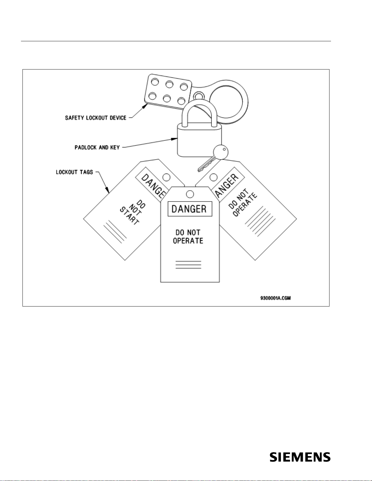
● Attach lockout tags to each lock indicating name of service person, date,
contact phone number, and purpose of the lockout.
● Use padlocks with only one key for all lockout purposes. If duplicate keys
exist, keep them under strict management supervision.
● Check for stored energy. Test the equipment to be sure that it will not
operate. Before beginning work, ensure that power is actually removed by
checking various points to ground with test meter. Even though power to the
device being serviced is removed, some points of the device may be
energized due to interconnections with other equipment. Such areas are
appropriately marked.
● The service person who locks and tags a machine must be the one who
unlocks it.
● Never remove a lock or tag that is not yours.
● Never lockout or tag equipment for another person.
● If a lock or tag needs to be left on during a shift change, the individual who
initiated the lockout shall transfer the lockout/tagout responsibility to an
authorized employee of the oncoming shift. If a lockout is left in place by a
previous shift and no transfer of responsibility has taken place, assume the
equipment is locked or tagged for a good reason; do not remove the
lockout. Contact your supervisor or manager who will make the decision on
how to proceed.
● Before removing a lockout and energizing the equipment, communicate to
all affected personnel in the area that the system is about to be reactivated.
Page 14
SIBAG HSD 3.0 Service Manual
6
Document No.: 747-01695, Rev. 03
2021-March-03
Safety
Figure 1 Lockout/Tagout Equipment Examples
Page 15
Service Manual SIBAG HSD 3.0
Document No.: 747-01695, Rev. 03
2021-March-03
7
Safety
1.5 Basic Safety Rules
Page 16

SIBAG HSD 3.0 Service Manual
8
Document No.: 747-01695, Rev. 03
2021-March-03
E-stop devices are not intended to disable equipment to provide
Safety
1.5.1 Basic Maintenance Safety Rules
The maintenance staff also plays a key role in the overall safety of the material
handling equipment. Creating and practicing a preventive approach to safety
helps establish an effective safety program.
● Lockout/tagout must take place before any service or maintenance work
begins per section 1.4 Control of Hazardous Energy (Lockout/Tagout.
● All maintenance or service is to be performed by qualified, trained personnel
only.
● Always report unsafe conditions or anything out of the ordinary to the
supervisor.
1.6 Safety Design Features
Baggage handling equipment has safety design features for worker protection.
Basic baggage handling safety design features are outlined on the pages that
follow.
1.6.1 Emergency Stop Devices
Illuminated red emergency stop (E-STOP) push-pull buttons, limit switches,
emergency pull cords, and other similar emergency stop devices are located
throughout the system for operator protection during emergency situations and
are for reaction to an incident or hazardous situation where imminent danger to
personnel exists.
These emergency stop devices are normally used at or near each potential work
station. E-stop devices are also provided at reasonable intervals throughout
material handling systems in areas routinely occupied by operations personnel.
protection for personnel in non-emergency circumstances. For example,
maintenance, jam clearing, and/or other similar activities require
adherence to established lockout/tagout procedures.
E-stops ideally control all movement visible from and related to the equipment or
location of the control device.
1.6.2 Emergency Stop Procedure
Emergency Stop and restart the entire system as follows:
1. Activate any E-STOP pushbutton (this will stop the associated conveyors).
2. Fix the reason for pushing the E-STOP pushbutton.
3. Reset the activated E-STOP pushbutton.
4. Pull the activated E-STOP pushbutton and restart the system as normal.
Page 17

Service Manual SIBAG HSD 3.0
Document No.: 747-01695, Rev. 03
2021-March-03
9
DANGER: Indicates an imminently hazardous situation that, if not avoided, will
WARNING: Indicates a potentially hazardous situation that, if not avoided,
Safety
1.6.3 Spill Guards
Many portions of material handling equipment run overhead and around areas
accessible to personnel. It is important that these areas be protected with spill
guards or other guarding design features.
1.6.4 Headroom and Aisles
When conveyors run above aisles, passageways or exits designated as fire exit
pathways, warnings will be provided if head clearance is less than 6 feet 8
inches (2 meters). The clearance of 6 feet 8 inches (2 meters) is measured from
the floor to the lowest part of the conveyor or guards. Other aisles or
passageways with less than 6 feet 8 inches (2 meters) clearance will be
protected by safety tape and warning signs.
In designated aisleways, all moving equipment parts to an elevation of 8 feet (2.4
meters) will be guarded.
1.6.5 General Guarding
When necessary for the proper protection of workers, it is required that areas be
properly guarded where equipment meets or exposed moving parts present a
potential hazard. It is recommended that warning and caution signs be
positioned in the employees’ line of sight.
Guarding shall never be removed or disabled for normal operations. Removal of
guarding shall only be done in accordance with established maintenance and
lockout/tagout procedures.
1.6.6 Safety and Warning Labels
Warning and safety labels are factory installed by the manufacturer or applied
after installation. Siemens equipment has safety labels attached with messages
warning of potential risks. These labels are located to be useful in any
application. Individual installations may have a unique need for additional labels
in other mounting locations. Therefore, more of the standard labels are readily
available.
These labels and signs may need to be supplemented by other warnings of
individual design that may be obtained from local sources or nationally
distributed catalogs.
result in death or severe injury. The use of danger labels is limited to the most
extreme situations
could result in death or severe injury
Page 18

SIBAG HSD 3.0 Service Manual
10
Document No.: 747-01695, Rev. 03
2021-March-03
CAUTION: Indicates a potentially hazardous situation that, if not avoided, will
Safety
result in minor or moderate injury. It may also be used to alert against unsafe
practices.
DANGER or WARNING should not be considered for property damage accidents
unless personal injury risk appropriate to these levels is also involved. CAUTION
is permitted for property-damage-only accidents. Sign placement shall be in the
immediate vicinity of the hazard, readily visible so the viewer can recognize the
hazard and take appropriate action.
Safety Signs and Labels Verification: On a quarterly basis, walk through the
entire material handling system and make sure that all safety signs and labels
are clearly legible and in good condition. Particularly if the system has been
reconfigured, verify that the signs and labels are still in the proper locations. If
there is a problem with any sign or label, reorder and replace it according to the
following identification and ordering pages.
Page 19
Service Manual SIBAG HSD 3.0
Document No.: 747-01695, Rev. 03
2021-March-03
11
Safety
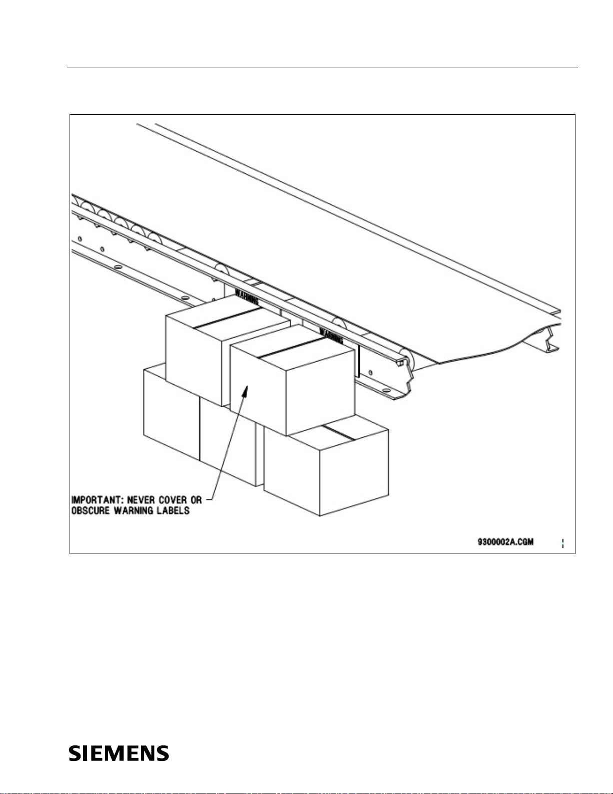
Figure 2 Safety and Warning Label Locations
Page 20

SIBAG HSD 3.0 Service Manual
12
Document No.: 747-01695, Rev. 03
2021-March-03
ANSI – American National
B 11.19 Performance Requirements for Risk Reduction Measures:
Z 535.5 Safety Tags and Barricade Tapes (NEMA)
CEMA – Conveyor Equipment
102 Term s and Defini tions
402 Bel t Conveyors
OSHA – Occupational Safety and
Health Administration
Subpart C (1917) Cargo Handling
1917.43 Powered Industrial Trucks
1917.49 Spouts, Chutes, Hoppers, Etc.
Subpart D (1910) Walking/Working
1910.21 Scope and Definitions
1910.30 Training requirements
Subpart J (l910) General
1910.144 Safety Color Codes for Marking Physical Haz ards
1910.147 The Control of Hazardous Energy (Lockout/Tagout)
Subpart N (1926) Cranes, Derricks,
1926.551 Cranes and Derricks
1926.555 Conveyors
Subpart O (1910) Machinery and
1910.211 Definitions
1910.219 Mechanical Power-Transmission Apparatus
Subpart S (1910) Electrical
1910.301 Introduction
1910.308 Special Systems
NFPA – National Fire Protection
Association
70E - Standard for Electrical Safety in the Work place
79 - Electrical Standard for Industrial Machinery
Safety
1.6.7 Additional Safety References
Standards Institute
Manufacturer's Association
Gear and Equipment
Surfaces
Safeguarding and other Means of Reducing Risk (AMT)
B 20.1 Safety Standard for Conveyors (ASME)
Z 535.1 Safety Colors (NEMA)
Z 535.2 Environ. and Facility Safety Signs (NEM A )
Z 535.3 Criteria for Safety Symbols (NEMA)
Z 535.4 Product Safety Signs and Labels (NEMA)
201 Safety Label Brochure
1917.44 General Rules Vehicles
1917.45 Cranes and Derricks
1917.46 Crane Load and Limit Devices
1917.48 Conveyors
1910.22 General Requirements
1910.23 Ladders
1910.25 Stairways
1910.28 Duty to have fall protection and falling object
protection
1910.29 Fall protection systems and falling object protection—
criteria and practices
Environmental Controls
Hoists, Elevators, and Conveyors
1910.145 Specifications for Accident Prevention Signs a nd T ags
1926.552 Material Hoists
1926.553 Base Mounted Drum Hoists
1926.554 Overhead Hoists
Machine Guarding
1910.212 General Requirements for All Machines
1910.302 Electric Utilization Systems
1910.303 General
1910.304 Wiring Design and Protection
1910.305 Wiring Methods, Components, and
Equipment-General Use
1910.307 Hazardous Locations
Page 21

Service Manual SIBAG HSD 3.0
Document No.: 747-01695, Rev. 03
2021-March-03
13
Introduction
Likewise, the
Those portions of this standard relating to maintenance and
Maintenance and service shall be performed by
condition, the user shall establish a maintenance
program to ensure that conveyor components are
, or
protect all persons or groups involved with the
Lockout/Tagout of Energy
5.4 Adjustment or Maintenance
. Wherever conditions
standards but such guarding would render the
serviceable and operational condition. Warning
kept clear of obstructions that could endanger
Routine inspections and corrective maintenance
operation unless proper maintenance or service
Safety
1.7 ASME B20.1-2012 Operational & Maintenance Safety
Portions of the ANSI “Safety Standards of Conveyors and Related Equipment”
(ASME B20.1-2012) relate to operational and maintenance personnel.
Accidents resulting from the manual handling of materials have been
reduced by the use of conveying and other forms of mechanical
handling equipment. A further reduction in the accident rate can be
gained by following safe practices in the design, construction,
installation, operation, and maintenance of such equipment.
The design and installation of conveyors and conveyor systems
should be supervised by qualified engineers.
maintenance of conveyors and systems should be supervised by
trained personnel.
The purpose of this standard is to present certain guides for the
design, construction, installation, operation, and maintenance of
conveyors and related equipment.
operation procedures are fully as important as those relating to
design and installation. The best design features may be negated by
faulty maintenance and operating practices. It is important that
operating and maintenance personnel be instructed in recognizing
hazards and pertinent safety precautions.
5.2 Maintenance (Repair)
a.
qualified and trained personnel.
b. Where lack of maintenance would cause a hazardous
maintained in a condition that does not constitute a
hazard to personnel.
c. No maintenance shall be performed when a conveyor
is in operation except as outlined in 5.3 and 5.4.
d. When a conveyor is stopped for maintenance or repair
purposes, the starting devices, prime movers
powered accessories shall be locked out or tagged out
in accordance with a formalized procedure designed to
conveyor against unexpected restart. Personnel should
be alerted to the hazard of stored energy, which may
exist after the power source is locked out. Refer to
ANSI Z244.1-1982, American National Standard for
Personnel Protection –
Sources – Minimum Safety Requirements and OSHA
29 CFR 1910.147 The Control of Hazardous Energy
(Lockout/Tagout).
e. All safety devices and guards shall be replaced before
starting equipment for normal operations.
5.3 Lubrication
a. Conveyors shall not be lubricated while in operation
unless it is impractical to shut down for lubrication. Only
trained and qu alified personnel who are aware of the
hazard of a conveyor in motion shall be allowed to
lubricate a conveyor that is operating.
b. Where the drip of lubricants or process liquids on the
floor constitutes a hazard, drip pans or other means of
eliminating the hazard shall be provided.
When adjustment or maintenance is required while equipment
is in operation, only trained and qualified personnel who are
aware of the hazard of the conveyor in motion shall be
allowed to make the adjustment or perform the maintenance
or service.
5.9.1 General Requirements of Guarding
5.9.1.3 Guarding Exceptions
prevail that would require guarding under these
conveyor unusable, prominent warnings shall be
provided in the area or on the equipment in lieu of
guarding.
5.9.1.4 Maintenance of Guards and Safety Devices.
Guards and safety devices shall be maintained in a
signs provided in accordance with 5.9.1.3 shall be
maintained in a legible, operational condition.
5.12 Operation
a. Only a trained person shall be permitted to operate a
conveyor. Training shall include instruction in operation
under normal conditions and emergency situations.
b. Where safety is dependent upon stopping devices or
starting devices or both, they shall be kept free from
obstructions to permit ready access.
c. The area around loading and unloading points shall be
personnel.
d. No person shall ride on a conveyor, unless it is a
conveyor engineered for that purpose.
e. Personnel working on or near a conveyor shall be
instructed as to the location and operation of pertinent
stopping devices.
f. A conveyor shall be used to t ransport only loads it is
designed to handle safely.
g. Under no circumstances shall the safety character istics
of the conveyor be altered without proper authorization
from the manufacturer.
h.
measures shall be conducted to ensure that all guards
and safety features are retained and function properly.
i. Personnel should be alerted to the potential hazard of
entanglement in conveyors caused by such items such
as long hair, loose clothing, and jewelry.
j. Conveyors shall not be maintained or serviced while in
requires the conveyor to be in motion. In which case,
personnel shall be made aware of the hazards and ho w
the task may be safely accomplished.
NOTE: Contact the American Society of Mechanical Engineers at
the address shown above for the complete ASME B20.1-2012.
NOTE: These excerpts are printed with the permission of ASME.
Page 22

SIBAG HSD 3.0 Service Manual
14
Document No.: 747-01695, Rev. 03
2021-March-03
Model Description
2 Model Description
The SIBAG High Speed Diverter 3.0 (HSD 3.0) is a device with two paddles
mounted on a horizontal belt conveyor used to divert the flow of one of several
bags by moving the paddles into the baggage stream. For better baggage flow,
the paddles are equipped with actively driven belts. The HSD 3.0 is designed to
be an integral part of a mainline belt conveyor sort system. The activated
paddles of the diverter form a 45 degree vertical powered belt wall for the
transfer of luggage from a main sort line to a pier chute or take-away conveyor.
The baggage contacts the diverter in a smooth, non-destructive manner, which
minimizes the impact forces applied during the sort process.
The HSD 3.0 is designed to handle virtually all types of normal baggage, but it is
not intended to process hazardous or volatile materials and liquids.
Figure 3 SIBAG HSD 3.0
Page 23

Service Manual SIBAG HSD 3.0
Document No.: 747-01695, Rev. 03
2021-March-03
15
Model Description
A single servo gearmotor efficiently powers the diverting action of the HSD 3.0,
rotating the paddles 45 degrees across the conveyor belt between their diverting
and non-diverting positions. It delivers motion to the pivot shaft of both the drive
side and non-drive side paddles simultaneously via a tie rod assembly. A drive
pulley powers the belt on each paddle.
When system control determines a need, the HSD 3.0 is energized, and the
paddle belts begin running. Diverter position is determined by the diverter control
panel by evaluating the output of the servo gearmotor encoder.
The HSD 3.0 is available in the configurations listed in Table 1. This manual
provides service and parts information for all versions.
Table 1 Available HSD 3.0 Versions
Part Number Conveyor Width Transition Width Hand
68.0021.100-01 39 in. 7 in. Left
68.0021.100-02 39 in. 7 in. Right
68.0021.100-03 39 in. 10 in. Left
68.0021.100-04 39 in. 10 in. Right
68.0021.100-05 1000mm 180mm Left
68.0021.100-06 1000mm 180mm Right
68.0021.100-07 1000mm 250mm Left
68.0021.100-08 1000mm 250mm Right
68.0021.100-09 1050mm 180mm Left
68.0021.100-10 1050mm 180mm Right
68.0021.100-11 1050mm 250mm Left
68.0021.100-12 1050mm 250mm Right
68.0021.100-13 45 in. 7 in. Left
68.0021.100-14 45 in. 7 in. Right
68.0021.100-15 45 in. 10 in. Left
68.0021.100-16 45 in. 10 in. Right
68.0021.100-17 1200mm 180mm Left
68.0021.100-18 1200mm 180mm Right
68.0021.100-19 1200mm 250mm Left
68.0021.100-20 1200mm 250mm Right
Page 24

SIBAG HSD 3.0 Service Manual
16
Document No.: 747-01695, Rev. 03
2021-March-03
Model Description
2.1 Description of Operation
The HSD 3.0 uses a Sinamics drive configuration with a Siemens programmable
servo control unit CU320-2 and two separate output channels (axles), one for
servo-positioning of the paddles (SERVO) and one for asynchronous movement
of the paddle-belts (VECTOR).
The main supply voltage is separate from the control voltage. Disconnect
and lock out/tag out both the main supply voltage and control voltage
before performing maintenance.
There is a Human Machine Interface (HMI) on the control panel door to select
manual or auto modes or to change settings.
A high level PLC with user-defined parameters is used which selects between
common signal exchanges wired to communicate via Digital I/O, PROFIBUS,
PROFINET, or Ethernet/IP interface (depending on how the HSD 3.0 was
ordered).
NOTE: The HSD 3.0 cannot hold the paddles in position when the power is off.
For that reason, the unit should always be powered unless maintenance is being
performed. If the unit needs to be removed from service, it should be disabled at
the PLC level (control room).
2.1.1 Hardware Overview
The HSD 3.0 is controlled by a Sinamics Drive System with programmable servo
control module. The control module is comprised of the following:
● Servo Control Unit Sinamics S120 CU320-2
● Smart Line Servo Power Module
● Double Servo Motor Module
● Servo gearmotor with absolute encoder for positioning
● Asynchronous motors without encoder for paddle belts
● Basic Operator Panel BOP20
Page 25

Service Manual SIBAG HSD 3.0
Document No.: 747-01695, Rev. 03
2021-March-03
17
Model Description
2.1.2 Diverter Control Panel (DCP) Status Light
A color indicator light shows the HSD status according to the following table.
Table 2 DCP Status Light Colors
Color Definition
Green Steady – Ready for automatic operation
Flashing – Ready for manual operation
Red Steady – Stopped or E-stopped
Yellow Steady – Fault
Flashing – Saving adjusted settings
Blue Steady – Motor overload
2.1.3 Basic Operation
In the BHS PLC operation, a bag arriving at the tracking photocell (provided by
BHS integrator), located at least 12 inches (305mm) upstream of the HSD 3.0 on
the conveyor bed, is checked to see if it requires diverting from the main
conveyor line. Once a determination is made, the diverter responds as outlined
below.
If the bag is to be diverted, one of the following occurs:
● If the diverter is in the RETRACTED position, the paddle belt drive pulleys
are started via a maintained PADDLE BELT RUN signal when the tracking
photocell is blocked, and when the bag is tracked nearly to the pivot point of
the first paddle, the servo gearmotor is energized via a leading edge trigger
of the EXTEND PADDLES signal so that the diverter is moved to the
EXTENDED position which will allow the bag to divert.
● If the diverter is already in the EXTENDED position, the paddle belt drive
pulleys are started when the tracking photocell is blocked, and the paddles
remain stationary, allowing the bag to divert.
After either case, the paddle belt motors shall continue to run for at least 20
seconds to allow for following sort operations without restarting the motors. This
20 second period is reset as each new bag passes the 12 inches (305mm)
upstream tracking photocell. If no sort action is required during those 20
seconds, the HSD 3.0 paddle belt drive pulleys are deactivated by the PLC
removing the PADDLE BELT RUN signals until the next time they are needed.
Page 26

SIBAG HSD 3.0 Service Manual
18
Document No.: 747-01695, Rev. 03
2021-March-03
Model Description
If the bag does not require diverting, the following occurs:
● If the diverter is in the EXTENDED position when the bag is tracked to
nearly the pivot point of the first paddle, the servo gearmotor is energized
via a leading edge trigger of the RETRACT PADDLES signal so that the
diverter will return to the RETRACTED position which allows the bag to
pass through. The paddle belt drive pulleys do not need to be activated for
this action.
● If the diverter is already in the RETRACTED position, the motors remain off
and the paddles remain stationary, allowing the bag to pass through.
Ideally, the HSD 3.0 motors are energized only when a sort action is required.
Additionally, the paddles are actuated to a different position only when required
to do so. If bag spacing is not adequate no sort action shall be attempted. The
HSD 3.0 will complete a position change actuation in approximately 310 ms (or
400 ms for widths over 1050 mm)
NOTE: Reliable operation of the diverter at chutes or parallel takeaways requires
a minimum “gap” between bags of at least 24 inches (610 mm). The average
length of each piece of baggage plus the 24 inch (610 mm) gap defines the bag
window size.
The PLC should also monitor for fault conditions in the HSD 3.0. If the HSD 3.0
does not complete an intended position change, the Servo Control Unit will
indicate a fault condition.
The HMI and the BOP20 will display the code for any alarms or faults. The list of
alarms and faults can be found in the Siemens Sinamics S List Manual.
The HSD 3.0 can be operated in three different modes, selected on the HMI
located on the HSD 3.0 Diverter Control Panel (DCP):
● Automatic
● Manual
● Settings
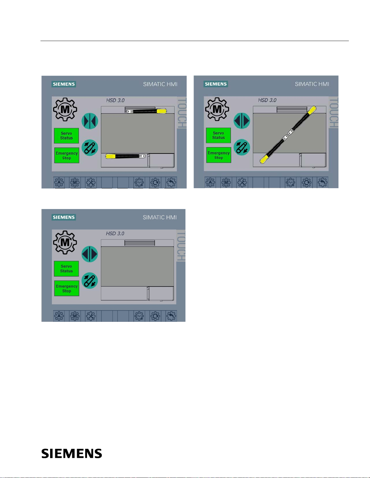
2.1.4 Human Machine Interface (HMI)
There is a Human Machine Interface (HMI) on the control panel door to select
manual or auto modes or to change settings. Both manual and settings modes
are available without the high level PLC running.
All screens have the following touch buttons at the bottom of the screen for
operation and navigation:
Page 27
Service Manual SIBAG HSD 3.0
Document No.: 747-01695, Rev. 03
2021-March-03
19
Model Description
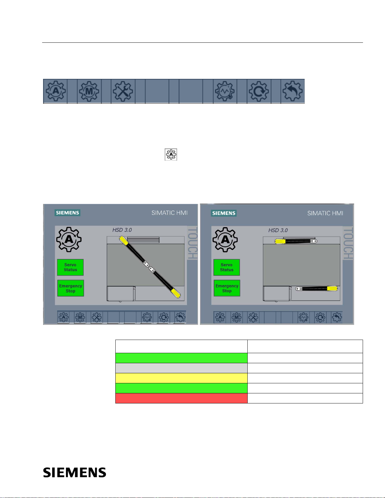
Figure 4 HMI Touch Button Symbols
AUTO MANUAL SETTINGS DIAGNOSTICS RESET BACK
Some screens can only be accessed with administrator-provided login privileges.
See section 3.3.3 Setup Using HMI.
2.1.5 Automatic Mode Operation
Touch the Auto button on the HMI on the door of the DCP for automatic
operation. The HMI displays the HSD paddles in their current positions. Servo
Status and Emergency Stop buttons indicate the status of the servo and e-stop.
Figure 5 HMI Automatic Mode
RH, Extended RH, Retracted
Table 3 Servo Status and Emergency Stop Button Status Colors
Button and Color Description
Servo Status Green Running; no servo fault
Servo Status Grey E-stop activated; no servo fault
Servo Status Yellow Servo fault present
Emergency Stop Green Running; no estop activated
Emergency Stop Red E-Stop activated
NOTE: Divert All Operation: If there is a need to divert all bags off of the
mainline, the Baggage Handling System (BHS) logic controller will need to
provide the signal to maintain the paddles in the extended position while the
diverter remains in the Automatic mode.
Page 28

SIBAG HSD 3.0 Service Manual
20
Document No.: 747-01695, Rev. 03
2021-March-03
Model Description
In Automatic mode, touch the Reset button to reset a fault after it has been
cleared.
There are two methods of controlling the HSD 3.0 in Automatic mode:
● Common input/output exchange through the use of 120 VAC or 24 VDC
control relays. These relays are located in the HSD 3.0 control panel and
are wired to the CU320-2 servo control unit.
● Network communications over PROFIBUS, PROFINET, or EtherNet/IP
There is a parameter in the HSD 3.0 drives that will select the method of control
in Automatic mode. This can be adjusted by using the HMI Settings screens,
Siemens Starter program, or by using the Basic Operator Panel on the HSD 3.0
drive. If this parameter is set to 0, the control relays will operate the HSD 3.0. A
setting of 1 will enable the PROFIBUS communications, etc.
NOTE:
When one of the network communication types is selected, it is still
necessary to make a direct electrical connection to the e-stop safety relay for a
safety stop to occur.
2.1.6 Manual Mode Operation
Touch the Manual button on the HMI on the door of the DCP for manual
operation. The HMI displays the HSD paddles in their current position. When the
HSD paddles are not in a known position (in between extend or retract), they are
not shown.
NOTE: When the HSD paddles are not shown, press the Retract button to
retract the paddles to the retract position, as shown in Figure 6 (LH, In Between).
This displays the paddles on the HMI screen and allows the BHS controller to
know the paddle positions when the HSD is returned to the Automatic mode.
In this mode, touching the Extend/Retract and Paddle Belt
buttons manually operate the HSD. Touching the Extend/Retract buttons will
return the paddles to the extend/retract positions saved in the memory. Touching
the Paddle Belt button will run the paddle belt. In this mode, the diverter will not
respond to BHS signals EXTEND PADDLES, RETRACT PADDLES, or PADDLE
BELT RUN.
NOTE: Divert All Operation: If there is a need to divert all bags off of the
mainline, the Baggage Handling System (BHS) logic controller will need to
provide the signal to maintain the paddles in the extended position while the
diverter remains in Automatic mode. Because Manual mode replaces the
automatic function signals from the BHS controller, the HSD 3.0 would no longer
have the ability to turn off the motors in the event of a cascade or normal timeout
situation. For this reason, it is not acceptable to use Manual mode for the
purpose of sustained Divert All operation.
Page 29
Service Manual SIBAG HSD 3.0
Document No.: 747-01695, Rev. 03
2021-March-03
21
Model Description
Figure 6 HMI Manual Mode
LH, Retracted LH, Extended
LH, In Between
Page 30
SIBAG HSD 3.0 Service Manual
22
Document No.: 747-01695, Rev. 03
2021-March-03
Model Description
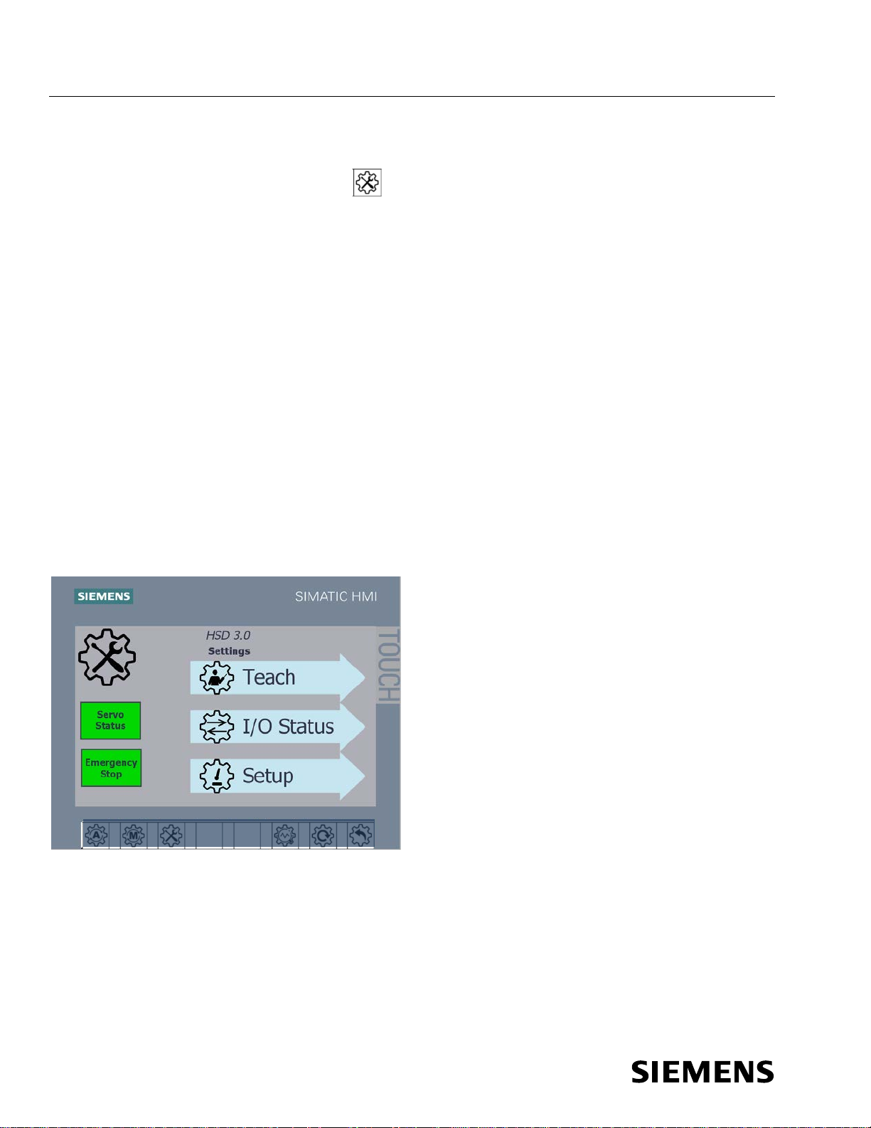
2.1.7 Settings Mode Operation
Touch the Settings button on the HMI on the door of the DCP for settings
mode. In this mode the Teach, I/O Status, and Setup buttons on the HMI are
enabled:
● Teach is used to define new end positions for the servo cycle commands.
The paddle extend and retract positions are factory configured, but
reconfiguring them might be necessary if the mechanism has been adjusted
or repaired. See section 5.4.2 Paddle Position.
● I/O Status is used to view the status of the outputs from the servo control
unit (first 6) and inputs to the servo control unit (last 4) for diagnostics and
troubleshooting. This screen is accessible without entering a password.
● Setup is used to set up the HSD by Siemens during manufacturing to
configure the communication type, conveyor width, and diverter hand. It is
used during installation commissioning by the system integrator to set the
speed. See section 3.3.3.2 Set Mainline Conveyor Belt Speed and Other
Options.
In this mode, the diverter will not respond to BHS signals EXTEND PADDLES,
RETRACT PADDLES, or PADDLE BELT RUN.
Figure 7 HMI Settings Screen
Page 31

Service Manual SIBAG HSD 3.0
Document No.: 747-01695, Rev. 03
2021-March-03
23
Fasten HSD conveyor bed to adjacent conveyor beds using Grade 5 (or Class 8.8) hardware.
Level the HSD bed.
Connect incoming power to diverter control panel.
Adjust the encoder and setpoint configurations using the Teach functions, if necessary.
Test to verify correct paddle belt speed.
Test the HSD operation.
Test the e-stop operation.
Installation
3 Installation
3.1 Installation Sequence and Startup Checklist
Lock Out and Tag Out procedures should be followed with respect to
both the mainline conveyor and the HSD 3.0 before performing this
checklist.
Table 4 Installation Sequence and Startup Checklist
Procedure Completed
Review service manual installation procedures.
Review installation layout and detail dr awings.
Remove the back covers and visually inspect all f actory wiring and inside devices for any damage
that may have occurred during shipment.
Install upstream, downstream, and takeaway conveyor beds (including belts and sideguards).
Manually move the paddles by hand. Operation should be smo oth with no binding or catch points.
Test to verify correct belt direction for paddle belts.
3.2 Mechanical Installation
3.2.1 Unloading and Handling
Each HSD is separately crated for easy fork-lift handling at the job site (see
Figure 8). When out of the crate, the HSD should only be handled from the
bottom with all of the packing removed. The HSD should only be handled with
the long length dimension perpendicular to the lifting forks.
Store each HSD separately, and do NOT stack any other materials on top
of the HSD.
Page 32

SIBAG HSD 3.0 Service Manual
24
Document No.: 747-01695, Rev. 03
2021-March-03
Installation
The weight of the HSD is 1530 lbs. (694kg) (approximately 1800 lbs. (816kg)
crated). While 74 percent of the weight is on the drive side of the unit, the weight
of the HSD is approximately equal from one end to the other.
Prior to installation, remove the back covers and visually inspect all factory wiring
and inside devices for any damage that may have occurred during shipment.
Notify Siemens immediately if any damage is visible.
If lifting with a crane, use straps under the unit with spreader bars to properly
distribute the load while preventing damage to the electrical control panel and
safety guarding.
Figure 8 Crated HSD
3.2.2 Unit Identification
Each HSD has an engraved serial number name plate mounted on the diverter
control panel. Each HSD may also have a conveyor identification number on the
rear cover. Refer to the separate installation layout drawings to determine where
each HSD will be installed.
3.2.3 Installation
NOTE: Adjacent conveyor beds must be installed and leveled prior to attaching
the HSD bed.
1. Lift HSD into position using forklift forks perpendicular to HSD bed.
2. Fasten four HSD conveyor assembly bed conveyor interface brackets to
upstream and downstream conveyor bed frames using 3/8 in Grade 5 (or 10
mm Class 8.8) hardware.
Page 33

Service Manual SIBAG HSD 3.0
Document No.: 747-01695, Rev. 03
2021-March-03
25
Installation
3. Level HSD bed.
4. Remove back covers and visually inspect all factory wiring and inside
devices for any damage that may have occurred during shipment.
5. Install conveyor bed belt and tension.
6. Install adjacent conveyor bed sideguards.
7. Match drill and install HSD area guards.
Figure 9 Area Guards
Additional area guards are required BY THE INTEGRATOR where a pinch
point exists at the tail of the divert side paddle against the sideguard.
3.3 Electrical Instructions
The HSD is delivered with a preconfigured memory module card in the Sinamics
servo control unit, which already contains a HSD standard project with
application program, as well as all typical motor and machine specific data
including the speed of the vertical paddle belts.
The encoder and setpoint configurations have also been factory adjusted, but
fine tuning may be required (see section 3.3.3.1 Teach Paddle Position). The
speed of the mainline conveyor belt running under the paddle arms shall be set
during installation commissioning by the system integrator (see section 3.3.3.1
Set Mainline Conveyor Belt Speed and Other Options). The HMI then calculates
and adjusts the paddle belt speeds to be compatible with the speed of the
mainline conveyor belt.
Page 34

SIBAG HSD 3.0 Service Manual
26
Document No.: 747-01695, Rev. 03
2021-March-03
Installation
The HSD comes with all the electrical devices wired to the terminal strip located
in the Diverter Control Panel (DCP) located on the frame of the HSD.
The HSD does not include a PLC or any other means of automated control, but
the motor controller provides the protection circuitry for each of the motors. The
automation controls are normally included in the sort line motor control panel that
is connected to the HSD on the terminal strip located in the DCP.
NOTE: The HSD cannot hold the paddles in position when the power is off. For
that reason, the unit should always be powered unless maintenance is being
performed. If the unit needs to be removed from service, it should be disabled at
the PLC level (control room).
NOTE: It is recommended to send a paddle positioning command (either extend
or retract) to the HSD during a system reset or system restart in order to return
the paddles to a known position.
3.3.1 Specifications
Although there are different versions of the HSD depending on where the HSD
will be installed, the specifications are almost identical, as shown in the following
table:
Table 5 Controls Specifications
Specification 120VAC Control 24VDC Control
Primary Power 380-500VAC, 50/60Hz, 10.7A 380-500VAC, 50/60Hz, 10.7A
Control Voltage 120 VAC, 1 phase, 60Hz 24 VDC
Controls Interface
3.3.2 Installation
1. Connect incoming and outgoing control signal wires to diverter control
2. Connect incoming power to diverter control panel.
NOTE: Paddle positions (encoder and setpoint configurations) are set before
shipment and should not need to be changed.
NOTE: In order to initiate safe torque off stop to machine, e-stop circuit should
de-energize CR265.
panel.
Digital I/O, PROFIBUS,
PROFINET, or Ethernet/IP
Digital I/O, PROFIBUS,
PROFINET, or Ethernet/IP
3. Connect e-stop relay to e-stop circuit for HSD operational area. Refer to
appropriate control panel drawing.
● Control Panel 68.0021.201 (PROFINET, Digital I/O, or EtherNet/IP Interface
with 120VAC control, US) requires 120VAC connection to CR265
Page 35

Service Manual SIBAG HSD 3.0
Document No.: 747-01695, Rev. 03
2021-March-03
27
Installation
● Control Panel 68.0021.202 (PROFINET, Digital I/O, or EtherNet/IP Interface
with 24VDC control, US) requires 24VDC connection to CR265
● Control Panel 68.0021.203 (PROFINET, Digital I/O, or EtherNet/IP Interface
with 24VDC Control, International) requires 24VDC connection to CR265
● Control Panel 68.0021.206 (Digital I/O only Interface with 120VAC control,
US) requires 120VAC connection to CR265
● Control Panel 68.0021.207 (Digital I/O only Interface with 24VDC control,
US) requires 24VDC connection to CR265
3.3.3 Setup Using HMI
3.3.3.1 Teach Paddle Position
The encoder and setpoint configurations have also been factory adjusted, but
fine tuning may be required. The HMI contains special “Teach Functions”. The
testing technician has to teach the actual extend/retract position values to the
setpoint parameters. (see section 5.4.2 Paddle Position).
3.3.3.2 Set Mainline Conveyor Belt Speed and Other Options
1. On Settings screen on HMI Teach, I/O Status, and Setup buttons on
HMI are enabled.
2. Touch Setup button. Setup screen displays (see Figure 10) and the
following two selections are enabled:
● Speed is used to configure HSD for mainline conveyor belt speed.
Touch Units button to select meters per second (MPS) or feet per minute
(FPM), then enter mainline conveyor belt speed (0.61-1.93 MPS or 120-380
FPM). Touch Check button to save setting.
NOTE: Paddle belt speed is adjusted automatically within servo control unit
to be 1.41 times entered mainline conveyor belt speed. This factor added to
paddle belt speed provides most efficient and stable diverting of baggage.
● Options is used to configure HSD for communication type, conveyor
width, and divert direction. This is done by Siemens during manufacturing
and does not need to be done during installation.
■ Communication pull down menu allows HSD to be configured for: I/O,
PROFIBUS, PROFINET, or EtherNet/IP.
■ Conveyor Width pull down menu allows HSD to be configured for: 39
inches, 45 inches, 1000mm, 1050mm, or 1200mm.
■ Divert Direction pull down menu allows HSD to be configured for:
Right Hand divert or Left Hand divert.
Page 36

SIBAG HSD 3.0 Service Manual
28
Document No.: 747-01695, Rev. 03
2021-March-03
Installation
NOTE: This screen requires username and password. Username is “setup” and
default password is “123”.
Figure 10 HMI Setup Screen
Figure 11 HMI Setup Opt ions and Setup Speed Screens
Options Speed
3.3.3.3 Managing Usernames and Passwords
To access the Administrator button to set up the HSD after installation:
1. Touch Settings button at bottom of screen, which displays Settings screen
(see Figure 7).
2. Touch Setup button on Settings screen, which displays Setup screen (see
Figure 12).
Page 37

Service Manual SIBAG HSD 3.0
Document No.: 747-01695, Rev. 03
2021-March-03
29
Installation
Figure 12 HMI Setup Screen Administrator Button
3. Administrators can then manage usernames and passwords by selecting
Administrator button and logging in using username “admin” and default
password “admin” (see Figure 13).
NOTE: Default passwords for usernames OEM and PLC User allow for easier
Siemens maintenance when service support is requested, but they may also be
changed by administrator.
Figure 13 HMI Admin Screen
3.3.3.4 PLC Automatic Mode – Digital I/O Relays
With the HSD in Automatic mode, the HSD 3.0 is prepared to accept operating
commands from the upstream PLC via the exchange relays. These signals can
either be 120 VAC or 24 VDC depending on the model of the HSD 3.0. The
signals are described in Table 2:
Page 38

SIBAG HSD 3.0 Service Manual
30
Document No.: 747-01695, Rev. 03
2021-March-03
Installation
Table 6 Input/Output Signals
Outputs Inputs
Main Disconnect On Motor Enable (E-Stop)
Fault Signal Move Paddle to Extended Position
Paddle in Extended Position Run Paddle Belts
Paddle in Retract Position Reset Fault
Automatic Mode On Move Paddle to Retract Position
Smart Line Module Ready
Control Unit Ready
3.3.3.5 PLC Automatic Mode – PROFIBUS, PROFINET, or EtherNet/IP
The HSD can also be controlled over the available remote PROFIBUS,
PROFINET, or EtherNet/IP communications port. In order to enable network
communications, the communication parameter must be set in the HMI. See
section 3.3.3.5 Set Mainline Conveyor Belt Speed and Other Options.
The network communication is broken down into three different telegrams. The
three telegrams represent the servo control unit, the servo drive, and the vector
drive. The telegrams consist of output words which are received from the
upstream PLC to control the HSD, and input words which are sent to the PLC to
provide status updates. In addition, the three telegrams contain the same
number of words, as illustrated in Table 7.
Table 7 Remote Telegrams
Telegram Output Words Input Words
Control Unit 4 4
Servo 4 4
Vector 4 4
Configuring the network communication to the PLC can be done in several ways.
One way is using the Siemens Starter program with the Drives ES package.
When using this program, the remote setup can be exported from Starter directly
into the Siemens Step 7.
A second method of configuring the remote network communication to the PLC
is using the GSD (PROFIBUS) or XML (PROFINET) file. This file is a readable
text file that contains general and device-specific specifications for
communications. The file is located on the compact flash memory card that
comes with the HSD 3.0 in the CU320-2 servo control unit behind the snap-in
operator panel.
When configuring the HSD 3.0 in the Hardware Configuration screen of SIMATIC
MANAGER, each of the telegrams must be set up as a separate object in
Page 39

Service Manual SIBAG HSD 3.0
Document No.: 747-01695, Rev. 03
2021-March-03
31
Installation
different slots. The objects should be configured as a Universal Module, with
each having the appropriate number of input and output words as shown in
Table 7, and in the same order (i.e., Control unit first, Servo unit second, and
Vector unit third.). Standard telegram 2 (PZD – 4/4) may be used in place of the
Universal Module. In addition, each of these objects must be separated by an
Axis Disconnector as shown in Figure 14.
Figure 14 Hardware Configuration Screen (SIMATIC Manager)
When configuring HSD 3.0 in TIA Portal, you need to install the software
package “SINAMICS Startdrive”, which can be downloaded from the Siemens
website. After the installation is finished, you have to add a “SINAMICS
S120/S150 CBE 20 V5.2” module from the hardware catalog to your hardware
configuration and define the PLC as PROFINET IO master in the network view of
your TIA project. Then double-click on the S120 device to open the Device view.
Add a “DO Control Unit” and a “DO Vector” module from the hardware catalog to
the S120 device. Add a Free telegram PZD 4/4 to the “DO Control Unit”, a
“Standard telegram 2, PZD-4/4; SERVO” to the “DO Servo” and a “Standard
telegram2, PZD-4/4; VECTOR” to the “DO Vector”. Define your IO address
Page 40

SIBAG HSD 3.0 Service Manual
32
Document No.: 747-01695, Rev. 03
2021-March-03
Installation
ranges. The Network view screen and the Device view screen should look like
the screens shown in Figure 15.
Figure 15 Config Screens (TIA portal)
Network view
Device view
Page 41

Service Manual SIBAG HSD 3.0
Document No.: 747-01695, Rev. 03
2021-March-03
33
Installation
To control the HSD via Ethernet/IP you need to add a “Generic Ethernet Module” into
the IO configuration of your PLC project and assign the following connection
parameters.
Figure 16 EtherNet/IP Configuration (Studio 5000)
Page 42

SIBAG HSD 3.0 Service Manual
34
Document No.: 747-01695, Rev. 03
2021-March-03
Installation
Inserting that module will create a device tag with an array of 12 input words (INT) and
12 output words (INT). The first 4 words represent the CU, the second 4 words the
SERVO and the last 4 words the VECTOR.
Figure 17 Tag List (Studio 5000)
Each of the telegrams is further broken down to provide specific status updates or
directly control the HSD 3.0. The following tables illustrate the items that compose the
telegrams. Please note that Siemens uses BIG-Endian format, so the 2 bytes in a word
are swapped.
NOTE: Items marked with * may not be available depending on the model of HSD 3.0
(i.e., a HSD 3.0 that is configured for remote control only will not have these items.)
Activating the commands in the output words is accomplished by turning the
appropriate bit from 0 to 1. For example, to command the HSD 3.0 paddles to move to
the extended position is accomplished by changing the signal of Bit 1 in the Servo
Output Word #1 from 0 to 1.
Some words are not broken down into individual bits, such as Servo and Vector Output
Words #2. These two words must have a value in them in order for the HSD 3.0 to
operate. The typical value is to make the value of these words to be 100, thus setting
the paddle and belt speeds to nominal settings, although the value can range from 50 –
150.
Page 43

Service Manual SIBAG HSD 3.0
Document No.: 747-01695, Rev. 03
2021-March-03
35
Installation
In addition, Bit 10 of Servo and Vector Output Words #1 must always be set to 1. If
these values are not 1, the HSD 3.0 will not recognize any other remote control
commands.
Servo Control Unit Input Word #2 indicates the status of the inputs and outputs on the
servo control unit itself.
Also, note that the “Go to Retract Position” and “Go to Extend Position” should never
both be active at the same time, otherwise a warning will occur and no movement will
be executed.
Page 44

SIBAG HSD 3.0 Service Manual
36
Document No.: 747-01695, Rev. 03
2021-March-03
WORD
BYTE
BIT
DESCRIPTION
0 (RESERVED FOR FUTURE USE)
1 2 3 4 5 6 7
8 9 10 11 12 13 14 15
0 (RESERVED FOR FUTURE USE)
1 2 3 4 5 6 7
8 9 10 11 12 13 14 15
(RESERVED FOR FUTURE USE)
(RESERVED FOR FUTURE USE)
WORD
BYTE
BIT
DESCRIPTION
0 1 2 3 4 5
PU FAULT – THERMAL OVERLOAD
6
MOTOR ENABLE (E-STOP) RELAY DE-
ENERGIZED
7
CONTROL UNIT FAULT PRESENT
8 9 10 11 12 13 14 15
0
DI 0: MOTOR ENABLE (E-STOP) RELAY
ENERGIZED
1
DI 1: HSD FAULT RESET
2
DI 2: PADDLE BELT NO MOTOR OVERLOAD
FAULT (1=OK, 0=FAULT)
3 4
REMOTE EXTEND PADDLE RELAY
5
PADDLE BELT RUN INPUT
6
DI 6: REMOTE RETRACT PADDLE RELAY
7
DI 7: SMART LINE MODULE READY
8 9 10
DI/DO 10: FAULT RESET SIGNALING FROM HMI
11
AUTO MODE
12
DI/DO 12: FAULT PRESENT
13
DI/DO 13: PADDLES IN EXTENDED POSITION
14
DI/DO 14: PADDLES IN (RETRACT) POSITION
15
DI/DO 15: CONTROL UNIT READY
FAULT CODE
DRIVE OBJECT WITH FAULT
Installation
Table 8 Control Unit Telegram Output Words
CONTROL UNIT
TELEGRAM
OUTPUT WORD
#1
CONTROL UNIT
TELEGRAM
OUTPUT WORD
#2
Table 9 Control Unit Telegram Input Words
CONTROL
UNIT
TELEGRAM
INPUT
WORD #1
CONTROL
UNIT
TELEGRAM
INPUT
WORD #2
CONTROL UNIT
TELEGRAM
OUTPUT WORD
#3
CONTROL UNIT
TELEGRAM
OUTPUT WORD
#4
CONTROL
UNIT
TELEGRAM
INPUT
WORD #3
CONTROL
UNIT
TELEGRAM
INPUT
WORD #4
Page 45

Service Manual SIBAG HSD 3.0
Document No.: 747-01695, Rev. 03
2021-March-03
37
WORD
BYTE
BIT
DESCRIPTION
0 GO TO RETRACT POSITION
1
GO TO EXTENDED POSITION
2 3 4 5 6
ACKNOWLEDGE FAULT
7
8 9 10
PLC CONTROL (SET TO 1)
11 12 13 14 15
(SERVO (PADDLE) SPEED SETPOINT
MEASURED IN PERCENTAGE
OF NOMINAL SPEED: 50 - 150%)
e.g., A VALUE OF 120 IN THIS WORD
WILL SET THE PADDLE SPEED TO
120% OF NOMINAL SPEED)
(RESERVED FOR FUTURE USE)
(RESERVED FOR FUTURE USE)
WORD
BYTE
BIT
DESCRIPTION
0 PADDLES IN RETRACT POSITION
1
PADDLES IN EXTENDED POSITION
2 3 4 5
SERVO DRIVE IN OPERATION
6
MOTOR ENABLE (E-STOP) RELAY DE-
ENERGIZED
7
SERVO FAULT PRESENT
8 9 10 11 12 13 14 15
(SERVO (PADDLE) ACTUAL SPEED
MEASURED IN PERCENTAGE
OF NOMINAL SPEED: 50 - 150%)
(SERVO (PADDLE) ACTUAL POSITION
COMBINED WITH OUTPUT WORD #4
TO FORM A DOUBLE WORD)
(SERVO (PADDLE) ACTUAL POSITION
COMBINED WITH OUTPUT WORD #3
TO FORM A DOUBLE WORD)
Installation
Table 10 Servo Telegram Output Words
SERVO
TELEGRAM
OUTPUT WORD
#1
SERVO
TELEGRAM
OUTPUT WORD
#2
Table 11 Servo Telegram Input Words
SERVO
TELEGRAM
INPUT WORD
#1
SERVO
TELEGRAM
INPUT WORD
#2
SERVO
TELEGRAM
OUTPUT WORD
#3
SERVO
TELEGRAM
OUTPUT WORD
#4
SERVO
TELEGRAM
INPUT WORD
#3
SERVO
TELEGRAM
INPUT WORD
#4
Page 46

SIBAG HSD 3.0 Service Manual
38
Document No.: 747-01695, Rev. 03
2021-March-03
WORD
BYTE
BIT
DESCRIPTION
0 PADDLE BELT RUN
1 2 3 4 5 6 7
8 9 10
PLC CONTROL (SET TO 1)
11 12 13 14 15
(VECTOR (BELT) SPEED SETPOINT
MEASURED IN PERCENTAGE
OF NOMINAL SPEED: 50 - 150%
e.g., A VALUE OF 120 IN THIS WORD
WILL SET THE BELT SPEED TO 120%
OF NOMINAL SPEED)
(RESERVED FOR FUTURE USE)
(RESERVED FOR FUTURE USE)
WORD
BYTE
BIT
DESCRIPTION
0 PADDLE BELT RUNNING STATUS
1 2 3 4 5
VECTOR DRIVE IN OPERATION
6
MOTOR ENABLE (E-STOP) RELAY DE-
ENERGIZED
7
VECTOR FAULT PRESENT
8 9 10 11 12 13 14 15
(VECTOR (BELT) ACTUAL SPEED
MEASURED IN PERCENTAGE
OF NOMINAL SPEED (50 - 150%
(RESERVED FOR FUTURE USE)
(RESERVED FOR FUTURE USE)
Installation
Table 12 Vector Telegram Output Words
VECTOR
TELEGRAM
OUTPUT
WORD #1
VECTOR
TELEGRAM
OUTPUT
WORD #2
Table 13 Vector Telegram Input Words
VECTOR
TELEGRAM
INPUT WORD
#1
VECTOR
TELEGRAM
INPUT WORD
#2
VECTOR
TELEGRAM
OUTPUT
WORD #3
VECTOR
TELEGRAM
OUTPUT
WORD #4
INPUT WORD
INPUT WORD
VECTOR
TELEGRAM
#3
VECTOR
TELEGRAM
#4
Page 47

Service Manual SIBAG HSD 3.0
Document No.: 747-01695, Rev. 03
2021-March-03
39
Installation
3.4 Initial Startup and Operation
Perform the following testing checks upon completion of installation to verify the
HSD unit is operating properly:
1. With main power turned off, manually move paddles by hand. Operation
should be smooth with no binding or catch points. Return paddle arms to
retract position.
2. Replace back cover and remove Lockout/Tagout devices.
NOTE: E-stop relay must be energized for diverter to operate.
3. Test HSD operation:
a. Turn disconnect switch to ON.
b. Touch HMI Manual button.
c. Touch HMI Paddle Belt button.
d. Paddle belts should be operating and HSD can be cycled by touching
HMI Extend and Retract buttons .
4. Touch HMI Auto button.
5. After first week of operation:
a. Check tracking and tension of paddle belts. Adjust as necessary. See
section 5.4.1 Paddle Belt Tracking and Tension.
b. Check for any loose hardware. Retighten as necessary.
Page 48

SIBAG HSD 3.0 Service Manual
40
Document No.: 747-01695, Rev. 03
2021-March-03
Conveyor Identification:
Dynamic Test Date:
Mechanical Static Inspection
Mechanical Dynamic Inspection
A R C N A R C N
1.5 Times Main Belt Speed
Inspected By
Date
Installation
3.5 Installation Inspection Report
SIEMENS HIGH SPEED DIVERTER 3.0 INSPECTION REPORT
Project Name: Project No.:
Location of Project: Static Inspection Date:
A = Accepted R = Rejected C = Corrected N = N/A
1
2
3
4
5
6
7
8
9
10
11
12
13
14
15
16
17
18
19
NOTES:
HSD identification
Paint Condition
Safety Labels
Cleanliness
Proper Installation of Floor Supports
Proper Installation of Hanger Supports
Mounting Hardware Grade 5 or Class 8.8
and Secure
Mounting Hardware on Drive Side Tight
Mounting hardware on Non-Drive Side Tight
No Sharp Edges or Burrs
No Baggage Snag Points
Vertical/Horizontal Alignment of Bed Joints
Proper Alignment of HSD Paddles
Access to HSD Controls Not Restricted
Maintenance Access Not Restricted
Guards Installed
Correct Mainline Belting
Correct Take-Away Belting
Take-Away Transition
20
21
22
23
24
25
26
27
28
29
30
31
Motor Operation (noisy/hot/sealed)
Bearing Operation (noisy/hot)
Belt Operation (noisy/smooth)
Smooth Operation of Paddles
Covers During Operation (rattles/rubbing)
Proper Timing for Paddle Positioning Signal
Unit Maintained in Off Position Until Needed
Take-Away Clear Monitoring
Proper Paddle Belt Direction of Rotation
Paddle Belt Speed is 1.4Paddle Belt Tracking and Tension Correct
Diverter Is Disabled When Local E-Stop Is Pressed
Page 49

Service Manual SIBAG HSD 3.0
Document No.: 747-01695, Rev. 03
2021-March-03
41
Preventive Maintenance
4 Preventive Maintenance
4.1 General
Do not perform adjustments, maintenance or other work on this
equipment without following OSHA Lock-Out/Tag-Out requirements and
state and local requirements. Failure to follow these requirements may
result in serious injury and/or equipment damage.
Unless otherwise specified, be certain that all equipment is de-energized
and power is turned off
Any damage found should be repaired or replaced before operating
equipment.
Standing or climbing on unit is dangerous to personnel and equipment.
In order to reduce down time and increase the life expectancy of various parts, it
is necessary that maintenance personnel become familiar with system
components and the periodic servicing that is required. Routine inspection of all
components is essential to reduce down time and to keep the system operating
efficiently.
Proper maintenance of the baggage handling system will ensure proper
operation and promote personnel safety during operation.
1. Replace broken or worn parts as soon as they are detected.
2. Safety guards must be properly attached to unit before and while operating
equipment.
3. Keep all CAUTION, WARNING, and DANGER safety labels clean and in
plain sight.
Page 50

SIBAG HSD 3.0 Service Manual
42
Document No.: 747-01695, Rev. 03
2021-March-03
Transition rollers free spinning
Daily
Cycle Diverter in Manual mode to check operation, paddle
Monthly
Visually inspect mounting hardware for tightne ss
Monthly
Diverter Control Panel Air
Clean or replace intake and exhaust air filt ers
Monthly, or as
Clean
Monthly
NOTE: These frequencies are based on an 18 hour day and 2 percent duty cycle (assuming the paddles are
Preventive Maintenance
4.2 Preventive Maintenance Schedule
Table 14 High Speed Diverter PM Tasks
Component Preventive Maintenance Task Time Interval
Entire Diverter, during
Inspect for unusual noises or vibrations Daily
Operation
Paddle alignment, paddle belt condition/ tracking, and no
Daily
debris obstructing paddles
Safety guards in place Daily
Diverter Control Panel, during
Status light illuminated green Daily
Operation
Entire Diverter, during Non-
Operational Hours
Clean out debris from between paddle and rear cover and
from the take-away transition rollers
Monthly
alignment, and paddle belt operation. See section 4.3.2.6
Cycle the Diverter to Verify Normal Operation.
Servo Gearmotor, during Non-
Visually inspect for oil leaks Monthly
Operational Hours
Diverter Control Panel, during
Inspect Status light indicator LED is functional Monthly
Non-Operational Hours
Filters, during Non-Operational
Hours
needed based
on site
conditions
Diverter Control Panel and
Visually inspect Monthly
Components, during NonOperational Hours
actuated to a divert/retract cycle 1500 t imes/day). Six months is equivalent to ap prox i m ately 500 hours and
275,000 cycles. One year is equivalent to appr oximately 1000 hour and 550,000 cycles.
NOTE: Adjust the frequency of inspection operation propo rt i onally for longer run times and/or higher duty
cycles.
Page 51

Service Manual SIBAG HSD 3.0
Document No.: 747-01695, Rev. 03
2021-March-03
43
Preventive Maintenance
4.3 Inspection
4.3.1 Daily Inspections during Normal Operation
Inspect each diverter for:
● No unusual noises or vibrations
● Proper alignment of the paddles
● Proper condition/tracking of the paddle belts
● No debris obstructing the paddles
● Transition rollers are free spinning
● Check that all safety guards are in place
● Control Panel Status light is illuminated green
Clean, repair or adjust the unit as necessary to ensure normal operation. If
immediate action cannot be taken, report the condition for action to be taken at
the earliest convenience. It may be necessary to take the HSD out of service
until repairs are possible if the conditions are severe enough.
4.3.2 Monthly Inspections during Non-Operational Hours
Turn each diverter control panel and main control panel and power off and
lockout/tagout the panel.
4.3.2.1 Diverter Control Panel (DCP)
The equipment and components located on the panels and in the cabinets
should be visually inspected as follows:
1. Open access door and inspect main disconnect.
2. Examine components and devices for correct mounting.
3. Examine all devices for evidence of excessive heat or burning.
4. Examine all wire and cable for burned, scorched or frayed insulation.
5. Examine all components or equipment for broken or damaged wires,
connectors, or terminals.
6. Dust panel, cabinet, and component surfaces using soft, lint-free cloth.
7. Clean or replace DCP intake and exhaust air filters in order to maintain
proper airflow through DCP. This inspection can be done as needed based
on site conditions.
4.3.2.2 Clean Out Debris
● Remove any accumulated debris between drive side paddle and rear cover
of HSD.
Page 52

SIBAG HSD 3.0 Service Manual
44
Document No.: 747-01695, Rev. 03
2021-March-03
Preventive Maintenance
● Remove any strings, tags, or other debris which would restrict rolling
operation of take-away transition rollers.
4.3.2.3 Servo Gearmotor Mount Hardware
Check that the mounting hardware (four screws and serrated flange lock nuts)
securing the servo gearmotor to the motor mounting bracket have not loosened.
Retighten as necessary. See section 5.4.4 Tightening Servo Gearmotor Mount
Hardware.
4.3.2.4 Check for Oil Leaks
Check the drip pan under the servo motor for oil. Also check the diverter frame
underneath the paddle belt motors for evidence of oil leakage.
After inspection is complete, replace any removed covers, remove lockout/tagout
and turn control panel power back on.
4.3.2.5 Check Control Panel Indicator Lights
Make sure the yellow Status light indicator LED is operational.
4.3.2.6 Cycle the Diverter to Verify Normal Operation
Use the HMI Manual mode to check the operation and alignment of the paddles
(see section 2.1.6 Manual Mode Operation). Also use the HMI Manual mode and
Paddle Belt buttons to check the operation of the paddle belts. When all
operation is considered satisfactory, return the HSD to Automatic.
Page 53

Service Manual SIBAG HSD 3.0
Document No.: 747-01695, Rev. 03
2021-March-03
45
Corrective Maintenance
5 Corrective Maintenance
5.1 General
Do not perform adjustments, maintenance or other work on this
equipment without following OSHA Lock-Out/Tag-Out requirements and
state and local requirements. Failure to follow these requirements may
result in serious injury and/or equipment damage.
Unless otherwise specified, be certain that all equipment is de-energized
and power is turned off
Any damage found should be repaired or replaced before operating
equipment.
Standing or climbing on unit is dangerous to personnel and equipment.
Proper maintenance of the baggage handling system will ensure proper
operation and promote personnel safety during operation.
1. Replace broken or worn parts as soon as they are detected.
2. Safety guards must be properly attached to unit before and while operating
equipment.
5.2 Lubrication
5.2.1 Roller Bearings
5.2.2 Pivot Bearings
3. Keep all CAUTION, WARNING, and DANGER safety labels clean and in
plain sight.
All roller bearings are grease filled by the manufacturer and do not require
maintenance.
All mounted pivot bearings are grease filled by the manufacturer and do not
require maintenance.
Page 54

SIBAG HSD 3.0 Service Manual
46
Document No.: 747-01695, Rev. 03
2021-March-03
Corrective Maintenance
5.2.3 Tie Rod End Bearings
All tie rod end bearings are grease filled by the manufacturer and do not require
maintenance.
5.2.4 Servo Gearmotor
NOTE: Gearmotors are considered lubricated for life unless leakage is observed.
If the unit is noisy, its life is considered over and it must be replaced. If it leaks,
refer to the manufacturers’ literature to replace the oil.
Page 55

Service Manual SIBAG HSD 3.0
Document No.: 747-01695, Rev. 03
2021-March-03
47
Corrective Maintenance
5.2.5 Drive Pulley
Only perform maintenance work after switching off the power. Lock and
tag out equipment. Open terminal box and disconnect the cables.
Figure 18 Drive Pulley Oil Level
Page 56

SIBAG HSD 3.0 Service Manual
48
Document No.: 747-01695, Rev. 03
2021-March-03
Chevron
NL Gear Compound 150
Corrective Maintenance
5.2.5.1 Oil Change – Van der Graaf Damage to the motor can result when using the wrong oil type. Refer to
the motor data label or Table 15. Do not use oils containing additives
which may damage the motor insulation or seals. Do not use oils
containing graphite, molybdenum disulphite or other electrically
conductive based oils.
All drive pulleys are factory filled with lubricant. It is recommended that oil
changes be performed every 2 years.
NOTE: Refer to the Van der Graaf Drum Motor manual for specific details.
1. Remove pulley from paddle assembly and place it on work bench. See
section 7.6.3 Paddle Drive Pulley.
2. Allow unit to cool to normal temperature.
3. Rotate drive pulley until oil plug is located in 6:00 o’clock position (bottom).
4. Unscrew oil plug and allow oil to drain completely. Collect oil in container
and examine it for wear metals. Dispose of it properly according to site
regulations.
NOTE: There may be internal pressure released when removing oil plug; this is
normal.
5. Refill pulley with approximately 750 ml of suggested oil type. See Figure 18
and Table 15.
6. Replace oil plug and install new copper seal.
7. Replace pulley in conveyor and run for 5-10 min.
8. Stop and lockout conveyor then open oil plug to vent it.
9. Close oil plug.
Table 15 Van der Graaf Drive Pulley Suggested Oil Types
Manufacturer Oil
Petro Canada Enduratex EP-150 Gear Oil
Castrol Molub-Alloy Gear Oil 84
Esso/Imperial Oil Spartan EP 150
Citgo EP Compound 150
Gulf EP Lubricant 140
Shell Omala 150
Sunoco SUNEP 150
Mobil Mobil G ear 629, SHC 150
Page 57

Service Manual SIBAG HSD 3.0
Document No.: 747-01695, Rev. 03
2021-March-03
49
Corrective Maintenance
5.3 Cleaning
5.3.1 Control Panel
Do not perform adjustments, maintenance or other work on this
equipment without following OSHA Lock-Out/Tag-Out requirements and
state and local requirements. Failure to follow these requirements may
result in serious injury and/or equipment damage.
Do not use water in cleaning electrical components. Damage to the
equipment may result.
Do not use compressed air to blow out debris.
Clean control panel internal components periodically as required. Some debris
could cause electrical shorts.
● Lubricate cabinet door hinges and door latches using light machine oil. Use
a soft cloth to remove any excess oil.
● Dust the panel, cabinet, and component surfaces using a soft, lint-free cloth.
● Diverter Control Panel Air Filters: Clean or replace intake and exhaust filters
monthly in order to maintain proper airflow through the Diverter Control
Panel.
5.4 Adjustment
5.4.1 Paddle Belt Tracking and Tension
When operating, the paddle belt V-guide should ride smoothly within the groove
of the motorized drive pulley. Adjust paddle belt tracking as necessary to prevent
the V-guide from wearing on the edge of the pulley groove.
NOTE: Material build up on the drive pulley or on the underside of the belt will
cause belt misalignment and possibly belt damage. Material build-up between
the belt and slide bed plate or rollers may also cause belt speed reduction and
increase the power requirement. Periodic cleaning will ensure a high drive
efficiency and good belt alignment.
1. Remove guards as necessary for access.
2. Remove top cover.
3. Loosen hardware securing both top and bottom clamp plate assemblies and
shaft clamp plates to upper mount plate and lower mount plate.
Page 58

SIBAG HSD 3.0 Service Manual
50
Document No.: 747-01695, Rev. 03
2021-March-03
Corrective Maintenance
4. By adjusting upper and lower tensioning nuts, square paddle drive pulley on
paddle to correct belt tracking. V-guide should be square to pulley groove.
5. Tighten upper and lower tensioning nuts evenly.
6. Tension is correct when slack is removed and belt does not slip on drive
pulley as it rotates. Tension should be equal across width of belt.
7. If belt is riding incorrectly, belt tracking is adjusted by slightly tightening or
loosening upper tension nut. It moves upper portion of drive pulley slightly in
or out, which causes belt to move up or down.
8. Tighten hardware securing top and bottom clamp plate assemblies.
9. Replace cover.
10. Replace guards.
5.4.2 Paddle Position
5.4.2.1 Setup of Position Setpoints: Quick Setup by Teach Functions
After repair or replacement of components, use the HMI to reset the retract
position and to reconfigure extend position setpoints. Parameter settings will be
executed automatically by the application program in the servo control unit.
5.4.2.1.1 Step 1: RETRACT Paddle Position
1. Touch Settings button on HMI then select Teach .
2. Log in.
NOTE: To access this screen, user must enter user name and password.
Username for Teach screen is “operator” and default password is “123”.
3. Fully retract paddle to retract position by touching Retract button.
Briefly touching Extend and Retract buttons will allow you to make fine
adjustments to alignment.
4. When paddle is in retract position, touch Check button to save setting.
5. Servo control unit will do absolute encoder calibration and RAM to ROM
copy. Saving procedure takes approximately 15 seconds. During that time,
do not touch screen or buttons. DCP status light on control panel door will
flash yellow during RAM to ROM copy and will turn off when finished.
NOTE: If the light does not flash yellow, the position is not being saved and it will
be lost at the next power cycle. If this happens, cycle power to the HSD to
reboot. After the reboot, perform the Teach operation again (steps 1 through 5)
and confirm that the yellow light flashes after the Check button is touched.
NOTE: Retract position must be set first before setting extend position
(otherwise, mechanism could crash in Manual or Automatic mode).
Page 59

Service Manual SIBAG HSD 3.0
Document No.: 747-01695, Rev. 03
2021-March-03
51
Corrective Maintenance
5.4.2.1.2 Step 2: EXTEND Paddle Position NOTE: In extended position, two paddles should form straight line.
1. While still logged in, move paddle to extended position by touching Extend
button. Briefly touching Extend and Retract buttons will allow you to
make fine adjustments to alignment.
2. When paddle is in extend position, touch Check button to save setting.
3. Servo control unit will copy actual position into second traversing block.
Saving procedure takes approximately 15 seconds. During that time, do not
touch screen or buttons. DCP status light on control panel door will flash
yellow during RAM to ROM copy and will turn off when finished.
4. Next, verify positioning. Touch Manual button on HMI and use
Extend/Retract buttons to manually operate HSD.
5. When complete, touch Auto button on HMI to return HSD to automatic
operation.
NOTE: In Automatic and Manual mode, diverter paddle will be moving between
retract and extend position at full speed. In settings mode, paddle will be moving
slowly between software limit switches/encoders to allow you to easily set retract
and extend positions.
Figure 19 HMI Teach Screens
Teach Retract (RH Shown) Teach Extend (RH Shown)
5.4.3 Setting Power Supply Output
The DC power supply has an adjustable output which should be set to 26VDC.
Adjustment is made by turning the slotted screw on the face of the power supply.
Page 60

SIBAG HSD 3.0 Service Manual
52
Document No.: 747-01695, Rev. 03
2021-March-03
Corrective Maintenance
Verify the voltage setting by using a DC voltage meter on the output terminals of
the power supply.
5.4.4 Tightening Servo Gearmotor Mount Hardware
Torque four serrated flange lock nuts (not screw heads) to 110 lb ft (150 Nm)
using a traditional 1/2” drive torque wrench with extension tool (Siemens
#68.0020.001-77) at a 90 degree angle to the torque wrench (Figure 20).
Figure 20 Torquing the Servo Gearmotor Mount Hardware
Page 61

Service Manual SIBAG HSD 3.0
Document No.: 747-01695, Rev. 03
2021-March-03
53
Troubleshooting
6 Troubleshooting
Troubleshooting tables are provided to assist you in diagnosing and resolving
symptoms that may occur during the normal operation of this equipment.
To use a troubleshooting table:
1. Identify equipment malfunction in left most column of table.
2. Identify most likely possible cause in center column.
3. Follow corrective measures outlined in far right column.
6.1 Mechanical Troubleshooting
6.1.1 Paddle Positioning
Malfunction Probable Cause Corrective Action
Paddles do not hold position
Paddles stop at partial stroke
Paddles are properly positioned
but transition side paddle is loose
Paddles are properly positioned
but both paddles are loose
Paddles do not move or move
erratically
Pivot clamp is broken or loose Tighten or replace pivot clamp.
Tie rod assembly broken or loose
Paddles move slowly as expected
when using teach function, but
operate erratically or crash when
operated in Manual or Automatic
mode
Servo gearmotor encoder or
setpoints incorrect
Servo gearmotor encoder or
setpoints incorrect
Long tie rod assembly broken or
loose
Drive side short dampened tie
rod assembly broken or loose
Servo gearmotor is broken Replace gearmotor.
Motor pivot arm is broken or
loose
One phase of the 3-phase input
voltage is missing
Adjust servo gearmotor encoder and
setpoints. See section 5.4.2 Paddle
Position.
Adjust servo gearmotor encoder and
setpoints. See section 5.4.2 Paddle
Position.
Retighten tie rod ends or replace tie
rod assembly.
Retighten tie rod ends or replace tie
rod assembly.
Tighten or replace motor pivot arm.
Retighten tie rod ends or replace tie
rod assembly.
Check upstream wire connections or
fuses to restore full power.
Page 62

SIBAG HSD 3.0 Service Manual
54
Document No.: 747-01695, Rev. 03
2021-March-03
Abnormal vibration
Servo motor damage
Replace motor.
a. Check conveyor belt for jams,
Bearings run noisily
Internal or seal damage
Replace bearing.
Bearings run hot
Conveyor overload
a. Check HSD for jams or obstructions.
Damage or defect in bearing
Replace bearing.
Troubleshooting
6.1.2 Servo Gearmotor (Motor)
Malfunction Probable Cause Corrective Action
Loose attachment hardware
Check and tighten screw connections.
Tighten installed servo gearmotor to
motor mounting bracket hardware (see
section 5.4.4 Tightening Servo
Gearmotor Mount Hardware).
Noisy motor Foreign objects inside motor Replace motor.
Damaged bearing Replace motor.
Motor overheats (surface
temperature greater than 140°C
[284°F])
(Temperature monitoring
responds)
Motor overload
Motor cooling impaired by
cleanliness
a. Check conveyor for jams or
obstructions. Clear and restart.
b. Check drive train for obstructions.
Clear and restart.
Clean surface of motor to improve heat
dissipation and ventilation. Ensure
cooling air flows in and out freely.
Incorrect voltage
Refer to the Electrical Troubleshooting
section of this manual.
Motor does not start No voltage
Refer to the Electrical Troubleshooting
section of this manual.
Conveyor jammed
obstructions, or excessive load.
Remove source of jam and restart
the system.
b. Check drive train for obstructions,
damage, or foreign matter. Clear
and restart.
Internal defect in motor Replace motor.
6.1.3 Pillow Block Bearings
Malfunction Probable Cause Corrective Action
Clear and restart.
b. Check drive train for obstructions.
Clear and restart.
c. Check conveyor bed is clean and
free of obstructions. Clean and
clear; restart.
or seal
Page 63

Service Manual SIBAG HSD 3.0
Document No.: 747-01695, Rev. 03
2021-March-03
55
Roller runs noisily
Loose or failed bearing
Replace roller.
Check for correct connections.
Check belt tension and reduce as
Incorrect power supply or
Troubleshooting
6.1.4 Paddle Nose Rollers and Drive Pulley
Malfunction Probable Cause Corrective Action
Roller rubs paddle frame
Improper paddle belt tension
Pulley does not run
Faulty electrical power or
connections
Motor winding phase or winding
short circuit (insulation) failure
Pulley or belt obstructed
Low ambient temperature/high oil
viscosity
Pulley runs hot High current draw
Load exceeds the capacity of the
high speed diverter
Excessive belt tension
Excessive/frequent stops/starts
frequency converter
Check roller for proper alignment and
adjust as needed.
Check belting for proper tension and
adjust as needed.
Check for correct power supply
voltage.
In a 3-phase unit, check for equal
voltage in all 3 phases.
Replace pulley. Contact
manufacturer for additional support.
Check belt and pulley are free from
obstructions and that all rollers and
pulleys rotate freely.
If the pulley does not rotate freely,
the cause might be a seize-up of
transmission or bearing. In this case,
contact manufacturer for additional
support.
a. Check if oil viscosity is suitable for
the ambient temperature. If not,
replace with oil having the correct
specification.
b. Contact manufacturer for
additional support.
Check the current draw and make
sure it is not higher than the rated
current on the nameplate.
Lessen the load on the unit and
space loads properly.
necessary.
Check if the number of stops/starts
meets the pulley’s specifications and
reduce frequency as necessary.
Install frequency converter to
optimize motor performance.
Check power supply.
Check if frequency converter settings
meet specifications and revise as
necessary.
Page 64

SIBAG HSD 3.0 Service Manual
56
Document No.: 747-01695, Rev. 03
2021-March-03
Incorrect power supply or
a. Check power supply.
Pulley trips overload or fuses
High current draw
Check current draw with an ammeter
Troubleshooting
Malfunction Probable Cause Corrective Action
Pulley runs intermittently, or
slower, or faster than specified
Pulley/belt is intermittently or
partially blocked
Check belt and pulley are free from
obstructions and that all rollers and
pulleys rotate freely.
Faulty electrical power or
Check for correct connections.
connections
Damaged transmission
Check rotation by hand. Replace
pulley or contact manufacturer.
frequency converter
b. Check frequency converter
settings meet specifications and
revise as necessary.
Incorrect pulley Check specification tolerances.
Belt slipping Check belt tension.
Pulley hums, starts very slowly,
or does not start at all
Electrical malfunction
Check for equal voltage on all 3
phases or open phase in the drive
pulley winding.
(to ensure no more than nameplate
current, and balanced in all 3 phases
(within 10 percent). If it is not, either:
● Voltage supply is not equal
● Short circuit is present in the
motor winding
Short in wires Check for short to the ground.
Pulley runs noisily Incorrect installation
Verify correct installation and tight
mounting hardware. In particular,
check that the four M8 screws
securing each upper and lower
mount plate are torqued to 30 lb ft
(40 Nm).
Excessive belt tension Loosen paddle belt tension.
Loose mounting brackets
Check mounting brackets, shaft
tolerances and fixing bolts.
Faulty/incorrect profile between
pulley and belt
Make sure the belt and pulley profiles
match and are engaged properly.
Replace if necessary.
One phase of power lead is not
connected properly
Check the cable connection and
correct if necessary.
Page 65

Service Manual SIBAG HSD 3.0
Document No.: 747-01695, Rev. 03
2021-March-03
57
Check mounting brackets, shaft
Pulley leaks oil
Loose oil fill screws
Tighten all screws.
Oil leakage around
Check glands and seals are tight and
Troubleshooting
Malfunction Probable Cause Corrective Action
Pulley runs with high vibration
Loose mounting brackets
Pulley out of balance
Faulty seal Replace pulley.
Shaft bearings damaged/worn
Motor winding failure
Incorrect frequency converter
settings
Excess grease in labyrinth
sealing
cable/terminal box due to:
● Loose cable connector gland
● Internal cable seal fault
● Loose connector gland
● Terminal box seal fault
Oil leakage around shell/end
house due to:
● End housing loose in shell
● End house / shell seal broken
One phase failed: Winding
isolation failure/ overload
Two phases failed: Power supply
failure on one phase causing
overload on the other two phases
/ isolation failure
Three phases failed: Motor
overloaded/wrong supply
connected
Check if frequency converter settings
meet specifications and revise.
tolerances and hardware. In
particular, check that the four M8
screws securing each upper and
lower mount plate are torqued to 30
lb ft (40 Nm).
Check if specifications for pulley
include static or dynamic balancing
and adjust.
Check the belt for excessive tension
and loading.
Check for water or chemical
infiltration.
Check for oil or grease leakage. (Oil
remains fluid and grease solidifies
when cold). Clean away excess
grease.
not subject to excessive heat or
chemicals.
Check between shell and end
housings for gaps.
Check for excessive belt tension or
shock loading.
Check for excessive heat or belt
tension and shock loading.
Check continuity, current and
resistance on each phase winding.
Replace pulley or contact
manufacturer.
Check supply voltage to all phases.
Check continuity, current and
resistance on each phase winding.
Replace pulley or contact
manufacturer.
Check correct supply voltage. Check
continuity, current and resistance on
each phase winding. Replace pulley
or contact manufacturer.
Page 66

SIBAG HSD 3.0 Service Manual
58
Document No.: 747-01695, Rev. 03
2021-March-03
Check application loading meets the
Shaft seal damaged/worn
Check for external contamination.
Drive pulley slipping
Check paddle belt tension and adjust
Troubleshooting
Malfunction Probable Cause Corrective Action
Shaft bearing failure Overload
Check application loading meets the
pulley specifications.
Shock loading
pulley specifications.
Excessive belt tension
Check belt tension and reduce if
excessive.
Lack of lubrication
Check oil level and installation of
pulley. If vertically mounted, check
pulley specifications.
Shaft stress or misalignment
Check for excessive screw tension
and frame or mounting bracket
misalignment.
Loose or tight bearing journal
Contact the manufacturer.
fitting
6.1.5 Paddle Belting
Malfunction Probable Cause Corrective Action
Belt wear on outside
Obstruction or debris
accumulated in belt path
Belt wear on inside Frozen paddle nose roller
Check belt path for damage or
obstruction and remove or correct as
needed.
Check paddle roller is clean and free
of obstruction.
Check rollers and pulleys for surface
damage or frozen bearings. Replace
as needed.
Belting tears Baggage impacts
Old belting, aged and brittle Replace belting.
Belt mistracking Drive pulley misaligned Square pulley and reset belt tension.
(V-guide wear) Nose roller misaligned Square roller and reset belt tension.
as needed.
Obstruction or debris
accumulated in the belt path
Check belt path for damage or
obstruction and remove or correct as
needed.
Trim loose belting or replace as
needed.
Page 67

Service Manual SIBAG HSD 3.0
Document No.: 747-01695, Rev. 03
2021-March-03
59
Diverter does not stop at retract
Servo gearmotor encoder or
Adjust encoder and setpoints. See
Upstream conveyor photoeye
Troubleshooting
6.2 Electrical/Controls Troubleshooting
6.2.1 Diverter Faults
Malfunction Probable Cause Corrective Action
Diverter does not cycle Diverter not in Automatic mode Touch Auto button on HMI.
Diverter disconnect is OFF
Servo control unit fault
DCP status light is illuminated
amber
Memory card corrupt (indicated
by LEDs on the control unit see
Figure 21)
Correct fault:
a. Verify control panel door is closed.
b. Servo gearmotor failure. See
section 6.1.2 Servo Gearmotor.
c. Inspect PLC output module.
d. Check motor contactor.
e. Check output module fuse.
f. Check incoming power.
Turn diverter disconnect to the ON
position.
Reload program onto memory card.
Teach new retract and extend
positions. See section 5.4.2 Paddle
Position.
If an error occurs while the servo
control unit is booted, booting is
aborted and the cause of the error is
indicated via the LEDs. See Figure
21. To correct, insert the memory
card with the correct software and
parameters.
If an error occurs after the servo
control unit is booted, see Figure 22.
position
Motor/paddles run backward
Diverter continuously jams
Diverter cannot be cycled using
HMI Manual Extend/Retract
buttons
setpoints incorrect
Divert Direction (Right Hand or
Left Hand) in HMI Setup\Options
section 5.4.2 Paddle Position.
Check Divert Direction setting. See
section 3.3.3 Setup Using HMI.
screen is set incorrectly
Sort object is moving or shifting
Check conveyor path for obstructions.
before the divert
Adjust sensor per drawing locations.
sensor alignment is wrong
Diverter not in Manual mode Touch Manual on HMI
Faulty input module
Check input module and replace as
needed.
Faulty HMI Check HMI and replace as needed.
Page 68

SIBAG HSD 3.0 Service Manual
60
Document No.: 747-01695, Rev. 03
2021-March-03
Troubleshooting
Figure 21 Servo Control Unit 320-2 LEDs During Booting
LED Status Comment
RDY COM OPT
Red Orange Orange Reset Hardware reset
RDY LED lights up red, all other LEDs
light up orange
Red Red Off BIOS loaded Red flashing
light 2 Hz
Red flashing
light 2 Hz
Red Off BIOS error
Red
Off File error
flashing
light 2 Hz
● Error occurred while loading the
BIOS
● Memory card not inserted or
defective
● Software on memory card not
present or corrupted
Red
Orange
flashing
Off FW loading
RDY LED lights up red, COM LED
flashes orange without fixed frequency
light
Red Off Off FW loaded Off Red Off
FW checked (no CRC
-
error)
Red flashing
light 0.5 Hz
Red
flashing
Off FW checked (CRC error) CRC invalid
light 0.5 Hz
Page 69

Service Manual SIBAG HSD 3.0
Document No.: 747-01695, Rev. 03
2021-March-03
61
Troubleshooting
Figure 22 Servo Control Unit LEDs during Operation
Page 70

SIBAG HSD 3.0 Service Manual
62
Document No.: 747-01695, Rev. 03
2021-March-03
Troubleshooting
Page 71

Service Manual SIBAG HSD 3.0
Document No.: 747-01695, Rev. 03
2021-March-03
63
A07441
Alert - Servo program reloaded
"Teach" paddle positions. See section
Troubleshooting
6.2.2 System Faults (Optional)
NOTE: The following faults may be displayed if the HSD is provided as part of
an integrated baggage handling system including operator workstations.
Malfunction Probable Cause Corrective Action
Diverter Failed to Extend Fault
Diverter Failed at Retract Fault
Diverter Failed to Retract Fault
6.2.3 Servo Faults
HSD was given a signal to
extend and failed to arrive at the
extend position
HSD was given a signal to
extend and remained in the
retract position
HSD was given a signal to
retract and failed to arrive at the
retract position
a. Check conveyor path for
obstructions.
b. Remove any lockout locks on the
diverter disconnect switches and
return disconnects to ON position.
c. Touch the Reset button on the
HMI. If that does not correct the
problem, touch the Manual button
on the HMI and use the
Extend/Retract buttons to
reposition paddles to verify proper
operation.
d. Check incoming power supplies.
e. Inspect for mechanical
obstructions.
f. Ensure control signals to input
module(s) in associated Motor
Control Panel (MCP) are being
received from diverter sensors.
g. Ensure input module(s) for
sensors are working correctly.
Malfunction Probable Cause Corrective Action
Servo control unit irregularities
(i.e. Excessive faults or failure to
read the program from the CF or
memory card)
F07452 Paddle jam or drag
F07464 Paddle jam or drag
A07479
Low power supply voltage
Alert - Paddle overtravel limit (-)
reached
Reset power supply to 26 volts by
using a flat blade screwdriver to adjust
the potentiometer on the lower front
surface of the power supply while
reading the output voltage from the
power supply with a meter.
5.4.2 Paddle Position.
Check paddles or positioning
mechanism for obstructions.
Reset fault.
Check paddles or positioning
mechanism for obstructions; if fault
cannot be reset, reinstall servo
program.
Reset fault.
Use paddle position controls to move
paddle back to normal range.
Page 72

SIBAG HSD 3.0 Service Manual
64
Document No.: 747-01695, Rev. 03
2021-March-03
"Teach" proper positions if necessary
Alert - Paddle overtravel limit (+)
Use paddle position controls to move
F07481
Paddle overtravel limit (-)
Manually move paddles to normal
F07490
Enable command removed during
Check for loose connection of auxiliary
F07800
No power to Smart Line Servo
Check circuit breaker CB1108.
F07840
Infeed command to servo missing
Check for continuity of thermal switch
F07860
Paddle belt motor overload
Check paddle belts for proper tracking
F07900
Servo motor locked or stalled
Clear paddle positioning mechanism.
Module if problem continuously
Troubleshooting
Malfunction Probable Cause Corrective Action
to maintain normal range. See section
5.4.2 Paddle Position.
A07480
reached
paddle back to normal range.
"Teach" proper positions if necessary
to maintain normal range. See section
5.4.2 Paddle Position.
exceeded
range.
Reset fault.
"Teach" proper positions if necessary
to maintain normal range. See section
5.4.2 Paddle Position.
F07482
Paddle overtravel limit (+)
exceeded
Manually move paddles to normal
range.
Reset fault.
"Teach" proper positions if necessary
to maintain normal range. See section
5.4.2 Paddle Position.
paddle positioning stroke
contact at main disconnect.
Reset fault
Power Module
F07801 Motor drive overcurrent
Reset fault.
Check paddle positioning mechanism
or paddle belt drive for obstructions.
Reset fault.
F07802 Three phase power missin g Restore power.
Reset fault.
F07841
F30002 Servo overvoltage
due to paddle belt motor shut
down
at paddle belt motor connector.
Reset fault (may be necessary to cycle
e-stop as well).
Infeed command to servo lost
during operation due to paddle
belt motor shut down
Check for continuity of thermal switch
at paddle belt motor connector.
Reset fault (may be necessary to cycle
e-stop as well).
and/or to make sure there is no debris
wrapped around the paddle belt rollers.
Reset fault.
Replace Smart Line Servo Power
Page 73

Service Manual SIBAG HSD 3.0
Document No.: 747-01695, Rev. 03
2021-March-03
65
repeats after reset.
F30005
Servo drive module overload
Replace Double Servo Motor Module if
F30600
E-stop fault
Cycle e-stop relay (CR265) to reset.
Troubleshooting
Malfunction Probable Cause Corrective Action
Reset fault.
F30003 Three phase power missin g Restore power.
Reset fault.
problem continuously repeats after
reset.
Reset fault.
F30021 Servo drive module ground fault
Replace Double Servo Motor Module if
problem continuously repeats after
reset.
Reset fault.
Reset fault.
F30611 E-stop fault Cycle e-stop relay (CR265) to reset.
Reset fault.
Page 74

SIBAG HSD 3.0 Service Manual
66
Document No.: 747-01695, Rev. 03
2021-March-03
Repair
7 Repair
This section provides removal and replacement procedures for spare parts and
commonly replaced components and assemblies. Some parts are contained in
assemblies. As you follow the removal steps to reach the part which is to be
replaced, you have to remove other parts. Inspect these parts for wear or other
problems and replace them at this time if worn.
NOTE: Before removing any drive components; mark the precise mounting point
of all components on the shaft. Also mark the position of the bearing on the
frame. This will minimize problems when re-aligning the components during
assembly.
NOTE: Use care when trying to reach a particular part, as damage can occur to
good parts.
In the procedure, when applicable, the number adjacent to the part referenced in
that step refers to a Figure and Item number, as in Figure 5-(9). If the figure
number is not repeated with an item number, it is understood that the item
number refers to the last figure that was referenced.
Do not perform adjustments, maintenance, or other work on this
equipment without following OSHA Lock-Out/Tag-Out requirements and
state and local requirements. Failure to follow these requirements may
result in death or serious injury and/or equipment damage.
Standard shop practices and safety procedures should be followed whenever
parts are removed or replaced.
● Make certain the system is locked out and tagged out before performing any
maintenance activities.
● Secure all hardware during installation.
● Clean parts and assemblies after installation.
● Re-install all guards or covers removed after any maintenance activities
before starting the conveyor.
Page 75

Service Manual SIBAG HSD 3.0
Document No.: 747-01695, Rev. 03
2021-March-03
67
Size
Torque
Wrench
(mm)
Size
Torque
Wrench
Hex Head Cap Screw
Skwezloc Head Cap Screw
M8 (8.8)
24 Nm
18 lb ft
13 mm
M4
7-8 Nm
65-70 lb in
T-25 mm
M10 (8.8)
48 Nm
35 lb ft
17 mm
M5
9-10 Nm
80-90 lb in
T-27 mm
M12 (8.8)
83 Nm
61 lb ft
19 mm
M16 (8.8)
200 Nm
147 lb
24 mm
Socket Head Cap Screw
Socket Head Flat Head Screw
M4 (8.8)
290 Nm
26 lb in
3 mm
M6 (10.9)
14 Nm
10 lb ft
4 mm
M6 (12.9)
16.5 Nm
12 lb ft
5 mm
M8 (10.9)
34 Nm
25 lb ft
5 mm
M8 (8.8)
24 Nm
18 lb ft
6 mm
M12 (10.9)
117 Nm
86 lb ft
8 mm
M12 (12.9)
150 Nm
110 lb ft
8 mm
Repair
7.1 Torque Values for Hardware
Table 16 Torque Values
(Class)
Size
7.2 Testing HSD Operation
Test the HSD operation after repairing or replacing components as required:
1. Turn disconnect switch to ON.
2. Touch HMI Manual button on HMI on door of DCP for manual
operation.
Size (mm)
3. Touch HMI Paddle Belt button to turn on paddle belt.
4. Paddle belts should be operating and HSD can be cycled by touching HMI
Extend or Retract buttons.
5. Reset encoder and setpoint settings if necessary. See section 5.4.2 Paddle
Position.
6. Touch HMI Auto button.
Page 76

SIBAG HSD 3.0 Service Manual
68
Document No.: 747-01695, Rev. 03
2021-March-03
Repair
7.3 High Speed Diverter Top Level Assembly
Figure 23 HSD Top Level Assembly
7.3.1 Long Tie Rod
Removal [Figure 23 – Item (9)]
1. Remove bottom covers (4) and pivot area cover (12).
2. Remove drive frame cover (5).
3. Remove tie rod end bearing (Figure 24-5) clamps.
4. Pull tie rod ends from pivot arm posts (Figure 26-8 and Figure 29-4).
5. Remove tie rod assembly (Figure 23-9).
Page 77

Service Manual SIBAG HSD 3.0
Document No.: 747-01695, Rev. 03
2021-March-03
69
Repair
Alternate Removal [Figure 23 – Item (9)]
1. Remove drive side tie rod end bearing clamp.
2. Pull drive side tie rod end from pivot arm post.
3. Remove screws and lockwashers securing transition pivot clamp weldment
(Figure 29-4) and front clamp shell (Figure 29-5) to shaft.
4. Remove shaft key (it may come off with clamp weldment).
5. Remove tie rod assembly with pivot clamp weldment attached to tie rod
(Figure 23-9).
Replacement [Figure 23 – Item (9)]
NOTE: Measure the length of the long tie rod being replaced and set the new tie
rod length the same.
1. Assemble tie rod onto both pivot clamp weldments (pivot arm posts).
2. Tighten tie rod end bearing clamps.
3. Check for paddle alignment and adjust tie rod length as necessary at loose
end. To align paddles:
NOTE: When in non-divert position, paddles should be parallel.
NOTE: When in divert position, each paddle centerline should align with pivot
axis of the paddle on the other side.
a. Position drive side paddle so it is even with edge of cabinet in back of
control panel.
b. Transition side paddle should be parallel to edge of HSD base.
c. Adjust transition side paddle position by manually turning long tie rod
until paddle is even and parallel with edge of HSD base.
4. Tighten tie rod end jam nuts.
NOTE: Apply Loctite 263 to bearing-side tie rod ends prior to reassembly. Do not
use Loctite on tube-side tie rod ends.
5. Replace drive frame cover.
6. Replace bottom covers and pivot area cover (centering this cover on paddle
pivot location).
NOTE: Insert tabs of bottom cover into lower angles of conveyor assembly (6)
before attaching with hardware.
7. Test HSD operation. See section 7.2 Testing HSD Operation.
Page 78

SIBAG HSD 3.0 Service Manual
70
Document No.: 747-01695, Rev. 03
2021-March-03
Repair
7.3.1.1 Tie Rods and Bearings (Long Tie Rod Assembly)
Figure 24 Tie Rod Assembly, Long
Removal [Figure 24
Tie Rods: Items (2) and (3)
Bearings: Item (5)]
1. Remove bottom covers.
2. Remove tie rod assembly. See section 7.3.1 Long Tie Rod.
3. Measure and record overall length of tie rod and note original orientation of
4. Loosen hanger bearing hex nuts (4) or (6) to remove rods (2) or (3).
Replacement [Figure 24
Tie Rods: Items (2) and (3)
Bearings: Item (5)]
1. Replace threaded rods into bearings (inserting threads all the way until
NOTE: Apply Loctite 263 to bearing-side threads of tie rods prior to reassembly.
Do not use Loctite on tube-side tie rod ends.
2. Replace threaded rods with hex nuts into tie rod tube.
hanger bearings (Figure 24-5).
bottomed out) and loosely install hex nuts.
3. Adjust overall length of tie rod assembly and orientation of bearings
according to notes made in Removal procedure.
Page 79

Service Manual SIBAG HSD 3.0
Document No.: 747-01695, Rev. 03
2021-March-03
71
Repair
4. Tighten hex nuts.
5. Replace tie rod assembly. See section 7.3.1 Long Tie Rod.
6. Replace bottom covers.
7. Test HSD operation. See section 7.2 Testing HSD Operation.
7.4 Conveyor Assembly
Figure 25 Conveyor Assembly
7.4.1 Return Roller
Removal [Figure 25 – Item (3)]
1. Remove guards as necessary for access.
2. Remove two nuts and washers fastening conveyor roller mounting bracket
(2) to conveyor frame weldment (1).
3. Support return roller (3) while removing screws.
4. Remove return roller from conveyor frame.
5. Remove mounting bracket from return roller shaft.
Replacement [Figure 25 – Item (3)]
1. Place mounting bracket on return roller shaft.
2. Hold return roller in place in conveyor frame weldment.
3. Replace screws in mounting bracket and through conveyor frame weldment.
Page 80

SIBAG HSD 3.0 Service Manual
72
Document No.: 747-01695, Rev. 03
2021-March-03
Repair
4. Replace nuts and washers on screws and finger tighten.
5. Tighten screws. See Table 16.
6. Replace guards removed for access.
7.5 Drive Subassembly
Figure 26 Drive Subassembly
Page 81

Service Manual SIBAG HSD 3.0
Document No.: 747-01695, Rev. 03
2021-March-03
73
Repair
7.5.1 Paddle Assembly (Drive Side)
Removal [Figure 26 – Item (2)]
1. Remove guards as necessary for access.
2. Disconnect drive pulley cable.
3. Remove power cable.
4. Pry open plug with small screwdriver.
5. Each wire is numbered. Document number of each wire and its position in
plug for replacement. The ground wire is not numbered, but its coloring
makes it unique.
6. Remove plug from cable.
7. Pull cable through shaft.
8. Remove hardware securing pivot clamp weldment (8) and rear clamp shell
(9) to shaft.
9. Loosen setscrews located in shaft clamp collars of both pivot bearings (14).
10. Slide paddle assembly (2) up to remove from drive weldment (1). This can
be done using wooden 2x4 board.
11. Remove shaft key (10) (it may come off as paddle assembly is removed).
Replacement [Figure 26 – Item (2)]
1. Lubricate shaft end with rust inhibiting lubricant.
2. Replace shaft key in shaft.
3. Align keyway and set paddle assembly into drive weldment, placing shaft
into pivot bearings.
NOTE: Install shaft with shoulder against inner race of pivot bearings.
4. Lightly tighten setscrews located in shaft clamp collars of both pivot
bearings to secure bearings to shaft.
5. Apply Loctite 263 (red) to screws and install pivot clamp weldment to rear
clamp shell finger tight. This secures shaft in place.
6. Check paddle alignment:
● Vertical alignment should be within 1/8 inch (3 mm). Check with straight
edge across top or bottom of paddles. Level paddles using pivot bearing
adjuster screws.
● Gap between drive side and non-drive side paddles should be 1/4 inch (6
mm).
● Offset between paddle center lines should be within 1/4 inch (6 mm).
7. Tighten screws securing pivot clamp weldment to rear clamp shell
(27 lb ft).
to 37 Nm
Page 82

SIBAG HSD 3.0 Service Manual
74
Document No.: 747-01695, Rev. 03
2021-March-03
Repair
8. Fully tighten setscrews located in shaft clamp collars of both pivot bearings
to secure bearings to shaft.
9. Reconnect drive pulley cable.
10. Replace guards removed for access.
11. Test HSD operation. See section 7.2 Testing HSD Operation.
7.5.2 Servo Gearmotor
Removal [Figure 26 – Item (15)]
1. Remove guards as necessary for access.
2. Mark and disconnect servo gearmotor power and control cables.
3. Measure and record overall length of short tie rod assembly and note
original orientation of hanger bearings (Figure 27-7).
4. Disassemble short tie rod assembly (Figure 26-7) by removing hardware
Figure 27-(8), (6), (11), and (9) securing tie rod plates (3) to tie rod block).
See section 7.5.4 Short Dampened Tie Rod Assembly.
5. Remove drip pan (Figure 23-39) beneath servo gearmotor.
NOTE: Place supports underneath servo gearmotor (Figure 26-15) to prevent it
from falling when motor mounting bracket (4) hardware is removed.
6. Remove hardware securing motor mounting bracket (4) to drive weldment
(1).
7. Remove hardware securing drive angle (3) to drive weldment (1).
The motor assembly is heavy (55kg/121 lbs.). Use multiple people and/or
a lifting device to prevent injury.
8. Lower motor mounting bracket with servo gearmotor and drive angle out of
drive weldment.
9. Remove ends of short dampened tie rod assembly (7) from motor pivot arm
(5).
10. Remove screw and motor hold-down plate (6) securing motor pivot arm (5)
to servo gearmotor (15) shaft.
11. Remove four screws and serrated flange lock nuts securing servo
gearmotor to motor mounting bracket.
Replacement [Figure 26 – Item (15)]
1. Fasten servo gearmotor to motor mounting bracket with four screws (with
Loctite 263) and serrated flange lock nuts. Torque nuts (not screw heads) to
110 lb ft (150 Nm) using special interchangeable head torque wrench
(example Snap-On #QD3IN200) along with 18mm box end head wrench
Page 83

Service Manual SIBAG HSD 3.0
Document No.: 747-01695, Rev. 03
2021-March-03
75
Repair
(example Snap-On #QYXM18A). See section 5.4.4 Tightening Servo
Gearmotor Mount Hardware.
2. Replace motor pivot arm on servo gearmotor shaft and secure with screw
and motor hold-down plate.
3. Replace ends of dampened tie rod assembly on motor pivot arm.
The motor assembly is heavy (55kg/121 lbs.). Use multiple people and/or
a lifting device to prevent injury.
4. Place motor mounting bracket and drive angle with servo gearmotor into
drive weldment, securing with hardware. Torque to 149 Nm (110 lb ft).
5. Reassemble short dampened tie rod assembly. Adjust overall length of
short dampened tie rod assembly and orientation of hanger bearings
according to notes made in Removal procedure. See section 7.5.4 Short
Dampened Tie Rod Assembly.
6. Reconnect servo gearmotor power and control cables.
7. Replace drip pan beneath servo gearmotor.
8. Replace guards removed for access.
9. If servo gearmotor is new, retract and extend positions will need to be
programmed. See section 5.4.2.1 Setup of Position Setpoints: Quick Setup
by Teach Functions.
10. Test HSD operation. See section 7.2 Testing HSD Operation.
7.5.3 Pivot Bearings
Removal [Figure 26 – Item (14)]
Replacement [Figure 26 – Item (14)]
1. Remove guards as necessary for access.
2. Loosen setscrews located in shaft clamp collars of both pivot bearings (14).
3. Remove paddle assembly (2). See section 7.5.1 Paddle Assembly (Drive
Side), Removal.
4. Remove both screws and hex nuts securing bearing flange block to bearing
mount plate (11).
5. Remove bearing.
1. Clean inner face of bearing and shaft. Lubricate with rust inhibiting lubricant.
NOTE: Apply Loctite 263 (red) to screws prior to bearing installation.
2. For bottom bearing, replace bearing and secure to bearing mount plate with
hardware and finger tighten. Orient bearing such that bearing shaft clamp
collar is on top.
Page 84

SIBAG HSD 3.0 Service Manual
76
Document No.: 747-01695, Rev. 03
2021-March-03
Repair
3. For top bearing, replace bearing and secure to bearing mount plate with
hardware and finger tighten. Orient bearing such that bearing shaft clamp
collar is on bottom.
4. Replace paddle assembly, aligning bearings with shaft so shaft is
perpendicular to transport belt and tighten setscrews. See section 7.5.1
Paddle Assembly (Drive Side), Replacement.
NOTE: Gap between drive side and non-drive side paddles should be 1/4 inch (6
mm). If both bearings are being replaced, it may be necessary to move them
around in the slot to achieve this gap.
5. Torque screws securing bearing flange block to bearing mount plate to 70 lb
ft (95 Nm).
6. Replace guards removed for access.
7. Test HSD operation. See section 7.2 Testing HSD Operation.
7.5.4 Short Dampened Tie Rod Assembly
Removal [Figure 26 – Item (7)]
1. Remove drive frame cover (Figure 23-5) and bottom covers (Figure 23-4).
2. Remove tie rod assembly if necessary:
3. Note original orientation of hanger bearings (Figure 27-7).
NOTE: Removing the entire tie rod assembly may not be necessary. It may be
easier to skip to step 4 to remove the tie rod plates and only remove the half of
the tie rod assembly needed to allow service to be performed.
a. Remove screws and lock washers securing pivot clamp weldment
b. Loosen tie rod hanger bearings Figure 27-(7) from pivot clamp
c. Pull ends of dampened tie rod assembly Figure 26-(7) up from pivot
d. Remove short dampened tie rod assembly (Figure 26-7).
4. Remove hardware Figure 27-(8), (6), (11), and (9) securing tie rod plates (3)
to tie rod blocks (1) and (2).
(Figure 26-(8), shaft key (10), and rear clamp shell (9) to paddle
assembly (2) shaft.
weldment Figure 26-(8) and motor pivot arm Figure 26-(5) by loosening
setscrews or eccentric lock collars.
clamp weldment Figure 26-(8) post and motor pivot arm Figure 26-(5)
post.
5. Loosen hanger bearing hex nuts Figure 27-(5) to remove threaded rods (4).
Replacement [Figure 26 – Item (7)]
NOTE: Apply Loctite 242 (blue) to both bearing-side threaded ends of both tie
rods (4) prior to reassembly.
Page 85

Service Manual SIBAG HSD 3.0
Document No.: 747-01695, Rev. 03
2021-March-03
77
Repair
1. Replace threaded rods into hanger bearings (inserting threads all the way
until bottomed out) and loosely install hex nuts.
2. Replace threaded rods into tie rod blocks Figure 27-(1) and (2) and loosely
tighten hex nuts.
3. Press bushing hubs Figure 27-(6) into holes of bushing tie rod block (1),
then press sleeves (11) into bushing hub.
NOTE: Apply Loctite 242 (blue) to threaded ends of screws Figure 27-(8) prior to
reassembly.
4. Replace screws and nuts securing tie rod plates to tie rod blocks.
5. Set overall length of tie rod assembly to 490mm (center of rod end to center
of rod end) and adjust orientation of bearings according to notes made in
Removal procedure.
6. Tighten hex nuts.
7. Replace tie rod assembly.
a. Loosely assemble short dampened tie rod assembly to pivot clamp
weldment and motor pivot arm with tie rod screw heads toward outside
of HSD.
b. Check for paddle alignment and adjust short dampened tie rod
assembly length as necessary at loose end.
NOTE: When in divert position, each paddle centerline should align with pivot
axis of the paddle on the other side.
8. Tighten tie rod bearing setscrews or eccentric lock collars.
9. Replace drive frame and bottom covers.
10. Test HSD operation. See section 7.2 Testing HSD Operation.
Page 86

SIBAG HSD 3.0 Service Manual
78
Document No.: 747-01695, Rev. 03
2021-March-03
Repair
Figure 27 Tie Rod Assembly, Short Dampened
7.5.5 Bumpers
Removal [Figure 26 – Items (12), (13)]
1. Remove drive frame cover (Figure 23-5).
2. Remove bumper assembly (Figure 26-(12) or Figure 26-(13)) from drive
weldment (1).
3. Remove bumper from bumper assembly bracket.
Replacement [Figure 26 – Items (12), (13)]
1. Replace bumper on bumper assembly bracket.
2. Replace bumper assembly on drive weldment.
3. Adjust bumper:
a. Adjust pivot shaft side bumper assembly (13) face to be 0.25-inches (6
mm) from short dampened tie rod assembly (7) bearing (14) when
paddle is in normal retracted position. See section 5.4.2 Paddle
Position.
Page 87

Service Manual SIBAG HSD 3.0
Document No.: 747-01695, Rev. 03
2021-March-03
79
Repair
b. Adjust drive side bumper assembly (12) face to be 0.04-inches (1 mm)
from short dampened tie rod assembly bearing when paddle is in normal
extended position. See section 5.4.2 Paddle Position.
4. Replace drive frame cover.
5. Test HSD operation. See section 7.2 Testing HSD Operation.
7.6 Paddle Assembly
Figure 28 Paddle Assembly
Page 88

SIBAG HSD 3.0 Service Manual
80
Document No.: 747-01695, Rev. 03
2021-March-03
Repair
7.6.1 Paddle Belt
Removal [Figure 28 – Item (10)]
1. Remove guards as necessary for access.
2. Remove top cover (8) and disconnect paddle motor connector, making note
of wire connections.
3. Loosen hardware securing both top and bottom clamp plate assemblies (6)
and shaft clamp plates (7) to upper mount plate (5) and lower mount plate
on paddle weldment (1).
4. Loosen lower and upper tensioning nuts on lower and upper mount plates.
5. Move paddle drive pulley (4) toward center of paddle to loosen paddle belt
(10) tension.
6. Remove paddle belt by sliding paddle belt upward until completely off of
paddle assembly.
7. While paddle belt is removed, clean underside of paddle belt and remove
material build-up between paddle belt and slide bed plate or rollers to
ensure high drive efficiency and good belt alignment.
Replacement [Figure 28 – Item (10)]
1. Slide paddle belt downward into place on paddle assembly around drive
pulley and nose roller (2).
2. Tension belt by moving drive pulley away from center of paddle. Keep drive
pulley square.
NOTE: Apply Loctite 242 (blue) to tensioning screws prior to reassembly.
3. Tighten upper and lower tensioning nuts evenly. Tension is correct when
slack is removed and paddle belt does not slip on drive pulley as it rotates.
Tension should be equal across width of paddle belt. Torque to 30 lb ft (40
Nm).
4. Track paddle belt. See section 5.4.1 Paddle Belt Tracking.
5. Tighten screws fastening both top and bottom clamp plate assemblies and
shaft clamp plates to upper and lower mount plates.
6. Replace top cover and connect paddle motor connector.
7. Replace guards removed for access.
8. Test HSD operation. See section 7.2 Testing HSD Operation.
7.6.2 Paddle Nose Roller
Removal [Figure 28 – Item (2)]
1. Remove guards as necessary for access.
2. Remove paddle belt (10). See 7.6.1 Paddle Belt, Removal.
Page 89

Service Manual SIBAG HSD 3.0
Document No.: 747-01695, Rev. 03
2021-March-03
81
Repair
3. Remove two screws securing paddle nose roller (2) to upper and lower
mount plates (5) on paddle weldment (1).
4. Remove nose roller.
Replacement [Figure 28 – Item (2)]
1. Place paddle nose roller between upper and lower roller mount plates.
2. Replace bottom screw securing paddle nose roller to lower mount plate.
3. Replace top screw securing paddle nose roller to upper mount plate.
4. Replace and tighten paddle belt. See section 7.6.1 Paddle Belt,
Replacement.
5. Replace guards removed for access.
6. Test HSD operation. See section 7.2 Testing HSD Operation.
7.6.3 Paddle Drive Pulley
Removal [Figure 28 – Item (4)]
NOTE: Paddle must be in the divert position.
1. Remove guards as necessary for access.
2. Remove paddle belt (10). See section 7.6.1 Paddle Belt, Removal.
3. Disconnect drive pulley electrical cable.
4. Loosen screws and washers securing bottom clamp plate assembly (6) to
bottom shaft clamp plate (7).
5. Remove screws and washers securing upper mount plate (5) to top of
paddle weldment (1).
6. Lift drive pulley (4) out of drive pulley spacer (3) and lower mount plate on
paddle weldment (1) with upper mount plate (5), top clamp plate assembly
(6), and top shaft clamp plate (7).
7. Remove screws securing top shaft clamp plate (7) to top clamp plate
assembly (6) and remove jacking screw.
8. Remove screws securing top shaft clamp plate (7) to upper mount plate (5).
9. Remove upper mount plate (5) from drive pulley (4).
Replacement [Figure 28 – Item (4)]
1. Replace screws securing top shaft clamp plate to upper mount plate (with
Loctite 242 blue).
2. Place upper mount plate on drive pulley shaft.
3. Replace screws securing top shaft clamp plate to top clamp plate assembly
(with Loctite 242 blue).
Page 90

SIBAG HSD 3.0 Service Manual
82
Document No.: 747-01695, Rev. 03
2021-March-03
Repair
4. Place drive pulley in lower mount plate on drive weldment and drive pulley
spacer.
5. Replace screws and washers securing upper mount plate to top of paddle
weldment (with Loctite 242 blue). Torque to 30 lb ft (40 Nm).
6. Tighten screws and washers securing bottom clamp plate assembly to
bottom shaft clamp plate.
7. Reconnect drive pulley electrical cable.
8. Replace paddle belt and adjust tracking and tension. See section 7.6.1
Paddle Belt, Replacement.
9. Replace guards removed for access.
10. Test HSD operation. See section 7.2 Testing HSD Operation.
Page 91

Service Manual SIBAG HSD 3.0
Document No.: 747-01695, Rev. 03
2021-March-03
83
Repair
7.7 Transition Subassembly
Figure 29 Transit i on Subassembly
7.7.1 Paddle Assembly (Non-Drive Side)
Removal [Figure 29 – Item (2)]
1. Remove guards as necessary for access.
2. Disconnect drive pulley cable.
3. Remove hardware securing transition pivot clamp weldment (4) and front
clamp shell (5) to shaft.
4. Loosen setscrews located in shaft clamp collars of both pivot bearings (8).
Page 92

SIBAG HSD 3.0 Service Manual
84
Document No.: 747-01695, Rev. 03
2021-March-03
Repair
5. Slide paddle assembly (2) up to remove from transition weldment (1). This
can be done using wooden 2x4 board.
6. Remove shaft key (6) (it may come off as paddle assembly is removed).
Replacement [Figure 29 – Item (2)]
1. Lubricate shaft ends with rust inhibiting lubricant.
2. Replace shaft key in shaft.
3. Align keyway and set paddle assembly into transition weldment, placing
shaft into pivot bearings.
NOTE: Install shaft with shoulder against inner race of pivot bearings.
4. Lightly tighten setscrews located in shaft clamp collars of both pivot
bearings to secure bearings to shaft.
5. Apply Loctite 263 (red) to screws and install pivot clamp weldment to front
clamp shell, finger tight. This secures shaft in place.
6. Check paddle alignment:
● Vertical alignment should be within 1/8 inch (3 mm). Check with straight
edge across top or bottom of paddles. Level paddles using pivot bearing
adjuster screws.
● Gap between drive side and non-drive side paddles should be 1/4 inch (6
mm).
● Offset between paddle center lines should be within 1/4 inch (6 mm).
7. Tighten screws securing pivot clamp weldment to front clamp shell to 37 Nm
(27 lb ft).
8. Fully tighten setscrews located in shaft clamp collars of both pivot bearings
to secure bearings to shaft.
9. Reconnect drive pulley cable.
10. Replace guards removed for access.
11. Test HSD operation. See section 7.2 Testing HSD Operation.
7.7.2 Pivot Bearings
Removal [Figure 29 – Item (8)]
1. Remove guards as necessary for access.
2. Loosen setscrews located in shaft clamp collars of both pivot bearings (8).
3. Remove paddle assembly (2). See section 7.7.1 Paddle Assembly (NonDrive Side), Removal.
4. Remove both screws and hex nuts securing bearing flange block to bearing
mount plate (3).
Page 93

Service Manual SIBAG HSD 3.0
Document No.: 747-01695, Rev. 03
2021-March-03
85
Repair
5. Remove bearing.
Replacement [Figure 29 – Item (8)]
1. Clean inner face of bearing and shaft. Lubricate with rust inhibiting lubricant.
NOTE: Apply Loctite 263 (red) to screws prior to bearing installation.
2. For bottom bearing, replace bearing and secure to bearing mount plate with
hardware and finger tighten. Orient bearing such that bearing shaft clamp
collar is on top.
3. For top bearing, replace bearing and secure to bearing mount plate with
hardware and finger tighten. Orient bearing such that bearing shaft clamp
collar is on bottom.
4. Replace paddle assembly, aligning bearings with shaft so shaft is
perpendicular to transport belt and tighten setscrews. See section 7.7.1
Paddle Assembly (Non-Drive Side), Replacement.
NOTE: Gap between drive side and non-drive side paddles should be 1/4 inch (6
mm). If both bearings are being replaced, it may be necessary to move them
around in the slot to achieve this gap.
5. Torque screws securing bearing flange block to bearing mount plate to 70 lb
ft (95 Nm).
6. Replace guards removed for access.
7. Test HSD operation. See section 7.2 Testing HSD Operation.
7.7.3 Transition Rollers
NOTE: The paddle may need to be in the divert position.
Removal [Figure 29 – Item (7)]
1. Press in on spring loaded end of transition roller (7) to compress internal
roller spring.
2. Remove transition roller.
Replacement [Figure 29 – Item (7)]
NOTE: Orient the transition roller so the spring-loaded shafts will be depressed
on the end farthest from the paddle pivot.
1. Place one end of transition roller in roller mounting hole in transition
weldment (1).
2. Compress internal roller spring and place other end of transition roller in
opposite roller mounting hole.
Page 94

SIBAG HSD 3.0 Service Manual
86
Document No.: 747-01695, Rev. 03
2021-March-03
7
10
12
13
27
28
41
29
30
32
38
40
42
44
46
97
62
49
51
52
57
48
23
(NOT
SHOWN)
(NOT
61
Repair
7.8 Control Panel
Figure 30 Control P anel, Inside
7.8.1 Motor Power Cable
Removal [Figure 30]
1. Turn off motor safety disconnect switch and apply lockout/tagout.
2. Remove servo gearmotor access panel.
SHOWN)
Page 95

Service Manual SIBAG HSD 3.0
Document No.: 747-01695, Rev. 03
2021-March-03
87
Repair
3. Open diverter control panel enclosure door.
4. Unplug motor power cable from servo motor module (52) in diverter control
panel.
5. Disconnect motor power cable from servo gearmotor (Figure 26-15).
Replacement [Figure 30]
1. Connect motor power cable to servo gearmotor.
2. Plug motor power cable into servo motor module in diverter control panel.
3. Close diverter control panel enclosure door.
4. Replace servo gearmotor access panel.
5. Remove lockout/tagout and turn motor safety disconnect switch on.
7.8.2 Motor Control Cable
Removal [Figure 30]
1. Turn off motor safety disconnect switch and apply lockout/tagout.
2. Remove servo gearmotor access panel.
3. Open diverter control panel enclosure door.
4. Disconnect motor control cable from top of servo power module (51) in
diverter control panel.
5. Disconnect motor control cable from servo gearmotor (Figure 26-15).
Replacement [Figure 30]
1. Connect motor control cable to servo gearmotor.
2. Connect motor control cable to top of servo power module in diverter control
panel.
3. Close diverter control panel enclosure door.
4. Replace servo gearmotor access panel.
5. Remove lockout/tagout and turn motor safety disconnect switch on.
7.8.3 Servo Control Unit and Memory Card Module
Removal [Figure 30
Servo Control Unit: Item (48)
Memory Card Module: Item (49)]
NOTE: Verify the voltage supplied by the power supply to the servo control unit
is set to at least 26 volts before replacing a perceived faulty servo control unit.
Too low a voltage will cause servo control unit irregularities such as the inability
to read the program from the memory card.
1. Turn off motor safety disconnect switch and apply lockout/tagout.
Page 96

SIBAG HSD 3.0 Service Manual
88
Document No.: 747-01695, Rev. 03
2021-March-03
Repair
2. Open diverter control panel enclosure door.
3. Remove preconfigured memory card module (49) from servo control unit
(48).
4. Remove servo control unit operator interface panel (62) by depressing
locking tabs on top and bottom.
5. Remove wire harnesses from servo control unit.
6. Lift servo control unit upward and separate from smart line servo power
module (51) to remove.
Replacement [Figure 30
Servo Control Unit: Item (48)
Memory Card Module: Item (49)]
1. Lower servo control unit into diverter control panel enclosure and slide
downward into notches on side of smart line servo power module.
2. Reconnect wire harnesses to servo control unit.
3. Set address switches on new servo control unit to match settings from old
servo control unit.
4. Reinstall servo control unit operator interface panel.
5. Reinstall existing preconfigured memory card module into servo control unit.
If it is necessary to reprogram new memory card module, see section 7.8.4
Reprogram Servo Control Unit.
6. Close diverter control panel enclosure door.
7. Remove lockout/tagout and turn motor safety disconnect switch on.
8. Test HSD operation. See section 7.2 Testing HSD Operation.
7.8.4 Reprogram Servo Control Unit
There are two typical scenarios for the process of reprogramming the servo
control unit. In one scenario, a replacement Compact Flash (CF) or memory card
is shipped with the HSD application pre-loaded onto the card. The other scenario
is that the application files are delivered electronically and that the existing CF or
memory card will be reused.
The reprogramming procedure is essentially identical for both scenarios. The
only difference is the preparation of the CF or memory card for those
installations where the existing CF or memory card will be reused. For these
installations, a computer with a CF or memory card reader and access to the
delivered HSD application files is required to complete this procedure.
The servo control module consists of four components: servo control unit,
memory card module (CF or memory card), smart line servo power module, and
servo motor module (Figure 31). Each of the servo control modules contains
LEDs that are used to identify faults and aid in reprogramming the memory
module.
Page 97

Service Manual SIBAG HSD 3.0
Document No.: 747-01695, Rev. 03
2021-March-03
89
SERVO CONTROL
Repair
Figure 31 Sinamics Servo Control Unit and Modules
UNIT
SMART LINE SERVO
POWER MODULE
SERVO MOTOR
MODULE
OPERATOR
INTERFACE PANEL
(MEMORY CARD
MODULE BEHIND IT)
[Figure 30 – Item (49)]
1. Turn off motor safety disconnect switch and apply lockout/tagout.
2. Open diverter control panel enclosure door.
3. Remove preconfigured Compact Flash (CF) memory card module (49) from
servo control unit (48).
a. If CF memory card is being discarded and new card is being used for
reprogramming, go to Step 6.
b. If CF memory card is being reused for reprogramming, continue with
Step 4.
4. Using computer with external CF memory card reader and access to HSD
application files, view memory card module contents. Figure 32 shows
typical file structure loaded on CF memory card.
Page 98

SIBAG HSD 3.0 Service Manual
90
Document No.: 747-01695, Rev. 03
2021-March-03
Repair
Figure 32 CF Memory Module Card Files
5. Erase all contents on CF memory card. Extract contents of HSD 3.0 ZIP file
(provided by Siemens) onto CF memory card. Contents of CF memory card
will be as shown in Figure 32.
6. Insert CF memory card module into servo control unit card slot.
The following steps require power to the servo control module and
lockout/tagout to be removed. Use extreme caution when working near
the control panel enclosure while power is applied.
7. Remove lockout/tagout and turn disconnect switch on door of diverter
control panel to ON position.
8. Wait for HMI Servo Status button to turn green. If it remains yellow, servo
fault is present. Touch Reset button to reset fault.
9. Touch Settings button on HMI on door of DCP for settings mode to enable
Teach, I/O Status, and Setup buttons. See section 2.1.7 Settings Mode
Operation.
Page 99

Service Manual SIBAG HSD 3.0
Document No.: 747-01695, Rev. 03
2021-March-03
91
Repair
10. Set retract and extend position positions. See section 5.4.2 Paddle Position.
A07441 Parameter Setting Alert will go away.
11. Set mainline conveyor belt speed (which automatically adjusts paddle belt
speed) and other options (communication, conveyor width, divert direction).
See section 3.3.3.2 Set Mainline Conveyor Belt Speed and Other Options.
12. Touch MANUAL button on HMI to test HSD operation. Paddles should now
cycle between previously taught positions. Paddle belts should also operate
normally.
13. Touch AUTO button on HMI.
Page 100

SIBAG HSD 3.0 Service Manual
92
Document No.: 747-01695, Rev. 03
2021-March-03
Parts
8 Parts
8.1 Locating Replacement Parts
The following pages contain exploded drawings and parts lists documenting the
components of this model. All numbered items indicate components or parts that
may require replacement.
To ensure that you order and receive the correct parts when you order
replacement parts, use the part number shown in the engineering drawings
and/or recommended spare parts list specific to your site. Include nameplate
information from motors, reducers, gearboxes, clutch/brakes, etc. whenever
possible.
To use this section to find replacement parts:
1. Locate the illustration and parts list in this chapter for the major assembly
the part belongs to in section 8.4 Illustrations and Parts Lists.
2. Find the desired item number on the illustration.
3. Note the complete description and part number for the desired item from the
part list and/or drawing. Also refer to the Recommended Spare Parts List to
verify the part number for your specific installation.
NOTE: Do not provide the item number assigned to the part. These numbers are
used for reference only.
8.2 Spare Parts
Spare parts held in stock avoid a loss of production over a longer period of time,
promote self-sufficiency, reduce costs, and are therefore economically feasible.
Even if all components of a system are optimally rated and designed, there are
certain inevitable factors which may cause downtime. Voltage surges,
detrimental ambient conditions, and short-comings in maintenance are only a
few of these factors.
The scope of your spare parts stock depends on the level of utilization. For
equipment with high levels of utilization, we recommend the stocking of complete
major assemblies in some cases.
 Loading...