

Siemens SI120,SI220 Configuration Manual

SI220, SI120
Control Unit
Configuration Manual
Version 1.0
Building Technologies
Fire Safety & Security Products

Liefermöglichkeiten und technische Änderungen vorbehalten.
Data and design subject to change without notice. / Supply subject to availability.
© 2009 Copyright by
Siemens Building Technologies
Wir behalten uns alle Rechte an diesem Dokument und an dem in ihm dargestellten Gegenstand vor. Der Empfänger erkennt diese Rechte
an und wird dieses Dokument nicht ohne unsere vorgängige schriftliche Ermächtigung ganz oder teilweise Dritten zugänglich machen oder
außerhalb des Zweckes verwenden, zu dem es ihm übergeben worden ist.
We reserve all rights in this document and in the subject thereof. By acceptance of the document the recipient acknowledges these rights
and undertakes not to publish the document nor the subject thereof in full or in part, nor to make them available to any third party without our
prior express written authorization, nor to use it for any purpose other than for which it was delivered to him.
About this document
This document contains instructions for the configuration of the control units SI120
and SI220. For information on operation please refer to the User Manuals of the
keypads.
Trademarks
SINTONY is a trademark of Fire & Security Products GmbH & Co. oHG.
All other product or company names mentioned in this document are trademarks or
registered trademarks of their respective owners and are used only for purposes of
identification or description.
Contacting us
If you have any questions or suggestions regarding the product or this manual,
please contact your local Siemens office.
Training courses
Siemens Fire & Security Products provides training courses for all products.

Contents
Safety .......................................................................................................9
1
1.1 Target readers...........................................................................................9
1.2 Work safety information ............................................................................9
1.3 Meaning of the written warning notices ..................................................10
1.4 Meaning of the hazard symbols..............................................................10
2 Product description ..............................................................................10
2.1 SI120.......................................................................................................10
2.1.1 System Information SI220 vs. SI120.......................................................11
2.1.2 System parameters SI220 vs. SI120 ......................................................11
3 Miscellaneous........................................................................................12
3.1 On Line Mode..........................................................................................12
3.2 Date/Time Change..................................................................................12
3.3 Keypads messages.................................................................................12
3.4 Auto Test 1/2 in.......................................................................................12
4 PIN User .................................................................................................13
4.1 User Name..............................................................................................13
4.2 Type of User............................................................................................13
4.2.1 Create User online ..................................................................................13
4.2.2 Delete User online...................................................................................14
4.2.3 Create User offline ..................................................................................14
4.3 Double PIN
since A8
....................................................................................14
4.3.1 Master PIN of next User..........................................................................15
4.4 Menu Access Rights ...............................................................................15
4.5 Duress PIN..............................................................................................15
4.6 Partition ...................................................................................................15
4.7 Partition Rights........................................................................................16
4.8 Full Set Rights.........................................................................................16
4.8.1 None........................................................................................................16
4.8.2 Partition ...................................................................................................16
4.8.3 Room (x) .................................................................................................16
4.9 Remote Access.......................................................................................16
5 RF Controls............................................................................................17
5.1 Partition ...................................................................................................17
5.2 Partition Rights........................................................................................17
6 Inputs .....................................................................................................18
6.1 Hardware Input........................................................................................18
6.2 Input Name..............................................................................................18
6.3 Logical Input Type...................................................................................18
6.3.1 Unused....................................................................................................20
6.3.2 Keyswitch Zone latching Full Set ............................................................20
6.3.3 Keysw. Full set blockschloss ..................................................................20
6.3.4 Keyswitch Zone latching Part Set ...........................................................21
6.3.5 Keyswitch Zone Pulse Full Set ...............................................................21
6.3.6 Keyswitch Zone Pulse Part Set...............................................................21
6.3.7 Final Setting Push Button .......................................................................21
6.3.8 Keypad disabled......................................................................................22
6.3.9 Lock Supervision.....................................................................................22
6.3.10 Geistiger Verschluss (GV) ......................................................................22
6.3.11 Set/Unset Lock........................................................................................22
6.3.12 Alarm Memory Reset (SI220 only)..........................................................22
6.3.13 Universal 1 / Universal 2 .........................................................................22
Siemens Building Technologies
Fire Safety & Security Products 07.2009
3

6.3.14 External Line Fault ..................................................................................23
6.3.15 Battery Supervision (SI120 only) ............................................................23
6.3.16 Silent Panic Alarm...................................................................................24
6.3.17 Audible Panic Alarm................................................................................25
6.3.18 Technical Alarm ......................................................................................26
6.3.19 Remote Assistance .................................................................................26
6.3.20 Fire ..........................................................................................................27
6.3.21 Tamper....................................................................................................27
6.3.22 BA 24h.....................................................................................................28
6.3.23 Vault Sensor 24h (SI220 only) ................................................................28
6.3.24 BA Full Set only.......................................................................................29
6.3.25 BA Full or Part Set ..................................................................................29
6.3.26 BA Part Set & BA Entry/Exit Full Set ......................................................30
6.3.27 BA Entry/Exit Full Set..............................................................................30
6.3.28 BA Entry/Exit Full or Part Set..................................................................31
6.3.29 BA Exit Terminator Full Set only .............................................................31
6.3.30 BA Access Zone......................................................................................32
6.3.31 BA Entry Route .......................................................................................32
6.3.32 BA Loop Follower Full Set.......................................................................33
6.3.33 BA Loop Follower Full or Part Set...........................................................34
6.3.34 Emergency Exit 1-5 (SI120: Emergency Exit 1-2) ..................................35
6.3.35 Panic Pushbuttons of Remote Keypads .................................................36
6.3.36 System Tamper.......................................................................................36
6.3.37 Mains Failure...........................................................................................37
6.3.38 Battery Failure.........................................................................................37
6.3.39 Transmission Failure...............................................................................38
6.4 Physical Type..........................................................................................38
6.5 Partition ...................................................................................................39
6.6 Bypassable..............................................................................................39
6.7 Delay .......................................................................................................40
6.8 Chime Option ..........................................................................................40
6.9 Audio / Video Address.............................................................................40
7 System Input..........................................................................................41
7.1 User Name ..............................................................................................41
7.2 Logical Type............................................................................................41
7.3 Partition ...................................................................................................41
7.4 Audio/Video Address...............................................................................41
8 Outputs...................................................................................................42
8.1 Hardware Output.....................................................................................42
8.2 Logical Output Type................................................................................42
8.2.1 Unused....................................................................................................44
8.2.2 External Bell ............................................................................................44
8.2.3 Internal Bell .............................................................................................44
8.2.4 Fire Bell ...................................................................................................44
8.2.5 Strobe......................................................................................................45
8.2.6 Safety Bell if Transmission failure...........................................................45
8.2.7 Safety Strobe if Transmission failure ......................................................45
8.2.8 Full Set Arming Impossible .....................................................................45
8.2.9 Part Set Arming Impossible.....................................................................45
8.2.10 Set/Unset LED on Keypad ......................................................................46
8.2.11 Full Set Confirmation...............................................................................46
8.2.12 Set/Unset Recorder.................................................................................46
8.2.13 Alarm for Recorder..................................................................................46
8.2.14 In Full Set ................................................................................................46
8.2.15 In Part Set ...............................................................................................46
4
Siemens Building Technologies
Fire Safety & Security Products 07.2009

8.2.16 Bypass forced Set...................................................................................46
8.2.17 Alarm in Memory.....................................................................................46
8.2.18 Technical Alarm ......................................................................................46
8.2.19 Panic Alarm.............................................................................................47
8.2.20 Burglar Alarm ..........................................................................................47
8.2.21 Tamper Alarm .........................................................................................47
8.2.22 Abort Alarm .............................................................................................47
8.2.23 Confirmed Alarm .....................................................................................47
8.2.24 Walk Test ................................................................................................48
8.2.25 Latching Sensor Reset............................................................................48
8.2.26 Door Lock Pulse......................................................................................48
8.2.27 Door Unlock Pulse ..................................................................................48
8.2.28 Buzzer .....................................................................................................48
8.2.29 Chime......................................................................................................49
8.2.30 Trouble (System).....................................................................................49
8.2.31 Blockschloss ...........................................................................................49
8.2.32 Blockschloss 2 ........................................................................................49
8.2.33 Blockschloss Bosch ................................................................................49
8.2.34 Emergency 1-5 (1-2 for SI120) ...............................................................50
8.2.35 Universal 1 / Universal 2 .........................................................................50
8.2.36 Calendar output 1 – 2 (SI220 only).........................................................50
8.2.37 Remote Control 1 – 2..............................................................................50
8.2.38 Video Recorder .......................................................................................50
8.2.39 Burglar for Transmission.........................................................................50
8.2.40 Seismic Activation...................................................................................50
8.2.41 RF Control 1 – 2......................................................................................51
8.2.42 Duress PIN..............................................................................................51
8.2.43 PIN Tamper.............................................................................................51
8.2.44 Battery Supervision (SI120 only) ............................................................51
8.2.45 Burglar Tamper alarm .............................................................................51
8.2.46 Valid PIN .................................................................................................51
8.2.47 Input Follower..........................................................................................51
8.2.48 Line Off Hook ..........................................................................................51
8.3 Partition ...................................................................................................52
8.4 Logic........................................................................................................52
9 Partitions................................................................................................53
9.1 Name.......................................................................................................53
9.2 Partition ...................................................................................................53
9.3 Allowed Keypads.....................................................................................54
9.3.1 All Keypads in Part Set ...........................................................................54
9.3.2 All Keypads when Unset .........................................................................54
9.3.3 All Keypads in Full Set ............................................................................54
9.4 External Bell............................................................................................54
9.4.1 When Part Set.........................................................................................54
9.4.2 Duration...................................................................................................54
9.4.3 By Fire.....................................................................................................55
9.4.4 RF Confirm..............................................................................................55
9.5 Internal Bell .............................................................................................55
9.5.1 When Full Set..........................................................................................55
9.5.2 Duration...................................................................................................55
9.5.3 By Fire.....................................................................................................55
9.6 Fire Bell ...................................................................................................55
9.6.1 Fire Bell Duration ....................................................................................56
Siemens Building Technologies
Fire Safety & Security Products 07.2009
5

9.7 Strobe Duration .......................................................................................56
9.8 Emercency Exit .......................................................................................56
9.9 Engineer Reset .......................................................................................56
9.10 Set possible.............................................................................................56
9.11 Setting with Alarm in Memory .................................................................56
9.12 Forced Set...............................................................................................57
9.13 Transmission...........................................................................................57
9.13.1 Burglar Alarm/P. Set ...............................................................................57
9.13.2 Tamper Alarm/P. Set...............................................................................57
9.13.3 Restore Transmission .............................................................................58
9.13.4 Transmission Verification Method...........................................................58
9.14 Input Verified Method ..............................................................................59
9.14.1 Combined Inputs .....................................................................................59
9.14.2 Pulse Counter .........................................................................................59
9.15 Bypass Mode ..........................................................................................59
9.16 Room Management.................................................................................60
9.17 Calendar..................................................................................................60
10 Keypads .................................................................................................61
10.1 Default Partition.......................................................................................61
10.2 Keypad Mode ..........................................................................................61
10.3 LEDs Keypad ..........................................................................................61
10.4 Buzzer On ...............................................................................................61
10.5 RF Control...............................................................................................62
10.6 Quick Set.................................................................................................62
11 Video.......................................................................................................63
11.1 Switching Time........................................................................................63
11.2 Video Keypad Address............................................................................63
11.3 Local Video active ...................................................................................63
11.4 Video Mode .............................................................................................63
11.5 Camera Switching Order.........................................................................63
11.6 Timeout ...................................................................................................63
11.7 Alarm with local Video.............................................................................64
11.8 Alarm on Camera ....................................................................................64
11.9 Camera Power Option.............................................................................64
12 System....................................................................................................65
12.1 Customer.................................................................................................65
12.2 Operator ..................................................................................................65
12.3 ARC Name ..............................................................................................65
12.4 Telephone ...............................................................................................65
12.4.1 Telephone Area Code.............................................................................65
12.4.2 Installer Telephone..................................................................................65
12.4.3 Sintony Telephone ..................................................................................66
12.4.4 MSN Number...........................................................................................66
12.4.5 Number of Attempts ................................................................................66
12.4.6 Number of Rings .....................................................................................66
12.4.7 Dialling Method .......................................................................................66
12.4.8 Line Monitoring........................................................................................66
6
Siemens Building Technologies
Fire Safety & Security Products 07.2009

12.5 Summer/Winter Time Change ................................................................67
12.6 Sylcom Access when Set........................................................................67
12.7 Up/Download Mode ................................................................................67
12.8 Delay Supervision ...................................................................................67
12.9 RF Supervision........................................................................................67
12.10 Print Style................................................................................................68
12.11 Flow Events Sort.....................................................................................68
12.12 Engineer Reset on ..................................................................................68
12.13 Engineer Reset Mode .............................................................................69
12.14 ISDN Access type ...................................................................................69
12.15 IP Settings (using Sylcom)......................................................................69
12.15.1 IP Address...............................................................................................69
12.15.2 IP Router .................................................................................................69
12.15.3 Port..........................................................................................................70
12.15.4 Router Port..............................................................................................70
12.15.5 Current Events ........................................................................................70
12.16 Type ........................................................................................................70
12.17 Verify Audio for Callback.........................................................................70
12.18 Custom Display.......................................................................................70
12.19 A/V ..........................................................................................................71
12.19.1 A/V Name................................................................................................71
12.19.2 Audio Address.........................................................................................71
13 ARC ........................................................................................................72
13.1 ARC2 Backup ARC1...............................................................................72
13.2 Serial Port Protocol (ARC1) ....................................................................72
13.3 Protocol ...................................................................................................73
13.4 Alarm Verification....................................................................................74
13.5 Listening in Time.....................................................................................74
13.6 Telephone Number .................................................................................74
13.7 Test settings............................................................................................75
13.7.1 Automatic Test ........................................................................................75
13.7.2 Automatic Test ........................................................................................75
13.7.3 Test Periodicity........................................................................................76
13.8 ARC Remote Access PIN .......................................................................76
13.9 ARC Remote Access Code.....................................................................76
14 Service ...................................................................................................77
14.1 Service 1 & 2...........................................................................................78
14.2 Telephone ...............................................................................................78
14.2.1 Site Number ............................................................................................78
14.2.2 Protocol (Service 2) ................................................................................79
14.2.3 GSM ........................................................................................................79
15 Input Transmission...............................................................................80
15.1 Transmission CMS/ARC 1 & 2................................................................80
15.2 Service 1 & 2...........................................................................................81
16 System Input Transmission .................................................................82
16.1 Transmission CMS/ARC 1 & 2................................................................84
16.2 Service 1 & 2...........................................................................................84
17 Calendars...............................................................................................85
17.1 Calendar Number....................................................................................85
18 Ebus Devices.........................................................................................86
Siemens Building Technologies
Fire Safety & Security Products 07.2009
7

18.1 Hardware Status .....................................................................................86
18.2 Ebus Devices ..........................................................................................86
18.2.1 Declared Number / Declared...................................................................86
18.2.2 Connected Number / Connected ............................................................86
19 Engineer Management..........................................................................87
19.1 Change personal PIN..............................................................................87
19.2 PINs Management ..................................................................................87
19.2.1 Create Engineer PIN ...............................................................................87
19.2.2 Delete Engineer PIN ...............................................................................88
19.2.3 Print Engineer PIN ..................................................................................88
19.3 Log Book .................................................................................................88
19.3.1 Display Global Log Book.........................................................................88
19.3.2 Display Access Log Book........................................................................88
19.3.3 Print Global Log Book .............................................................................88
19.3.4 Print Access Log Book ............................................................................88
19.3.5 Unreset Counter......................................................................................89
19.4 Engineer Reset .......................................................................................89
19.5 System Programming..............................................................................89
19.6 Telecom Options .....................................................................................89
19.7 Time Functions........................................................................................89
19.8 Tests........................................................................................................89
19.8.1 Walk Test ................................................................................................89
19.8.2 Input Test ................................................................................................89
19.8.3 Soak Test ................................................................................................90
19.8.4 Output Test..............................................................................................90
19.8.5 Transmission Test...................................................................................90
19.8.6 Listen Test...............................................................................................91
19.8.7 Setting Test .............................................................................................92
19.8.8 Autotest ...................................................................................................92
19.9 E-Bus Options .........................................................................................93
19.9.1 Addressing E-Bus ...................................................................................94
19.9.2 Delete E-Bus devices..............................................................................95
19.9.3 Configuration E-Bus ................................................................................95
19.10 Radio Devices .........................................................................................96
19.10.1 Address Radio.........................................................................................96
19.10.2 Delete Radio ...........................................................................................97
19.10.3 Configuration Radio ................................................................................97
20 System Panel.........................................................................................98
20.1 Recording of messages ..........................................................................98
20.2 Control Panel ..........................................................................................98
20.2.1 Program Version EPROM.......................................................................98
21 Disposal .................................................................................................98
8
Siemens Building Technologies
Fire Safety & Security Products 07.2009

1 Safety
1.1 Target readers
Safety
Target readers Qualification Activity Condition of the
Operational startup
personnel
Service personnel Technical training for
Technical training for
electrical installations.
Training on the product
is necessary.
electrical installations.
1.2 Work safety information
z Read the safety precautions in the attached flyer before installing the device.
z Keep this document for reference.
z Always pass this document on together with the product.
z Please also take into account any additional country-specific, local laws, safety
standards or regulations concerning installation, operation and disposal of the
product.
Puts the product into operation for the first time, or
changes the existing configuration.
Checks the product at regular intervals to ensure that it
is in good working order,
services the device or system and repairs it or expands and upgrades the
system.
product
The product is installed
but not yet configured,
or the existing configuration is to be changed.
Product already in use
and requiring servicing.
Radio interference with other devices in the environment / EMC
z This is a Class A device. This equipment may cause radio interference in a resi-
dential installation. In this case the user is encouraged to perform appropriate
measures to correct the interference.
z The unit operates on frequencies that are approved for use in the European Un-
ion. When used outside the EU, the national regulations for the use of frequencies must be observed.
Damage due to unsuitable mounting location
z The environmental conditions recommended by the manufacturer must be ob-
served.
z Do not operate the device close to sources of powerful electromagnetic radia-
tion.
z Do not operate the device in dusty places.
z The device should only be used for indoor applications.
z Do not expose the device to mechanical vibrations or shocks.
z Protect the device against moisture.
Dangerous situation due to false alarm
z Make sure to notify all relevant parties and authorities providing assistance be-
fore testing the system.
z To avoid panic, always inform all those present before testing any alarm devices
Siemens Building Technologies
Fire Safety & Security Products 07.2009
9
Product description
1.3 Meaning of the written warning notices
The severity of a hazard is indicated by the following written warning notices.
Signal word Type of hazard
WARNING Possible danger of death or severe bodily harm
IMPORTANT Malfunctioning may result
1.4 Meaning of the hazard symbols
Warning of dangerous electrical voltage
Warning of a hazard
Warning of dangerous electrical voltage
2 Product description
The described functions in this manual are based on the firmware of Sintony SI22x.
NOTE
TM means Engineer Menu.
[TM1] means Engineer Menu point 1.
2.1 SI120
This configuration manual includes also the explanation for the SI120 according
the Sylcom Software. The most essential differences are listed below.
NOTE
The following points differ from the SI220 structure.
Some of the configuration parameters in the menus are aranged differently compared to SI220. One
reason is the system limits and the less functionality.
10
Siemens Building Technologies
Fire Safety & Security Products 07.2009

2.1.1 System Information SI220 vs. SI120
si220 si120
RF controls 21 7
Inputs 48 22
System Inputs 10 6
Outputs 49 23
Partitions 6 2
Keypads 7 3
Transmissions 48 22
System Transms. 89 45
Users 49 20
Calendars 8 2
Expanders 10 4
2.1.2 System parameters SI220 vs. SI120
SI220 SI120
Menu tree „offline mode“ Menu tree „offline mode“ Description
RF Controls Similar RF Controls
Input
– Alarm Memory reset
– Vault Sensor 24H
– Emergency Exit 1-5
– Not availible
Inputs – physical Type
- Glass break detector
Outputs
– Emergency 1-5
– Blockschloss Bosch
– Calender Output 1-2
Partitions
– Master, Slave, Virtual
Calendar
– output directly controlled by
calendar
Less types are available
– Not available
– Not available
– Emergency Exit 1-2
– Battery Supervision
Less types are available
- Not available
Less types are available
Emergency 1-2
Not available
Not available
Less parameters available
– Not available
Less paramenters available
– not available
The input types are listed in a different order.
The output types are listed in a different order.
Product description
11
Siemens Building Technologies
Fire Safety & Security Products 07.2009

Miscellaneous
3 Miscellaneous
3.1 On Line Mode
Up/Download Transmission
Download During a download the parameters which were programmed in Sylcom are loaded to the central control unit
Upload During an upload the Control panel parameters are transferred to a computer running on Sylcom (Control
Read Log B 500 events will be read out of the panel.
Characters Only country specific special characters can be entered in Sylcom (inputs, outputs name…). All other charac-
Requirement for a remote connection:
z The control panel must be connected to the telephone network.
z For a successful transmission, the “Sintony Tel" and the "Site Number" parameters in the System menu
must match with the Sylcom customer file.
(PC --> Control panel).
panel --> PC).
ters are not allowed.
3.2 Date/Time Change
[TM 71] Change date
and time
This menu function is used to change the date and time. The clock is immediately updated after confirmation.
The hours must be entered using the 24 hour system. The change of date and time is written to the log.
3.3 Keypads messages
[TM5171] Partition Assign a keypad message to a chosen partition for a customer information
Free text 1/2 Two lines of free text each consisting of 16 characters can be entered here.
Switch on display The user-defined display can be “activated” and “desactivate” here.
The letters, numbers and some special characters are present as a multiple assignment on the remote keypad.
NOTE
After the user has logged out, there is the possibility to delete this message.
3.4 Auto Test 1/2 in
Auto Test 1 / 2 in This initializes the start time of the possible two tests.
NOTE
Set the “Test periodicity” in the menu ARC. Default setting is 24 h.
12
Siemens Building Technologies
Fire Safety & Security Products 07.2009

PIN User
4 PIN User
NOTE
Configuration of user at Sylcom is only availabe in online mode!
4.1 User Name
The current user name can be replaced by any freely definable name (maximum
16 characters). Each must have a unique name.
4.2 Type of User
6 or 4 digits PINs can be defined with or without blocking of the keypad after 3
wrong attemps. This option is selectable by TM 5172. By creating a new user, a
code is always given by control panel: you can change it or not.
[TM 25] Print User Pin This menu function enables all the parameters of user PIN's to be printed out via the serial interface. A
printer can be directly controlled or instead a terminal program.
The printout can be stopped by typing "X". For printing, the PC/printer-cable SAQ 11 must be con-
nected to the control panel main board on the connector J7. A serial printer or a PC terminal program
can be used for printout.
4.2.1 Create User online
WARNING
[TM 22] Creating a new user “new pin” in on line mode will always set the next free
parameter from “unused” user to “End user”.
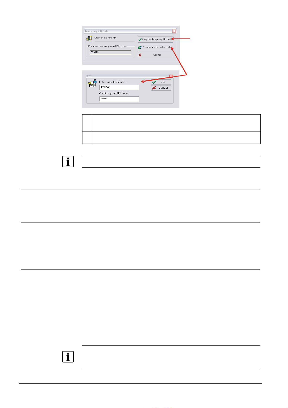
Choose between a temporary and definitive user code.
There is no possibility to change the PIN code of an existing user by Sylcom;
therefore you have to change the PIN Code at the keypad.
13
Siemens Building Technologies
Fire Safety & Security Products 07.2009
PIN User
1 Keep this temporary PIN code:
You accept this proposed PIN for the moment, but you MUST change it when you log in next
time. You will not be able to perform any other actions before the PIN has been changed.
2 Change to a definitive code:
Enter your desired PIN code and confirm it. This is the definite PIN Code for this user
To create the same PIN Code twice is not possible, Sylcom will deny it with the message „wrong PIN“.
1
2
4.2.2 Delete User online
[TM 23] Deleting a user “Delete Pin” in on line mode will also delete the user ac-
count and set the parameter from “End user” user to “unused”.
4.2.3 Create User offline
[TM 22] Select a user and change the „End User “parameter from „unused“.
The first time you login with the temporary user code at the keypad, you have to
change to a definitive user code
4.3 Double PIN
since A8
Chose the PIN option of the two possibilities:
z A “Single PIN” user is the usual case adding a new user. During logon proce-
dure only 1 PIN is required.
z A “Master PIN of next user” is to add for more security. 2 PINs are needed for
authorization to access the keypad menu.
If a user is defined with single PIN, to change it to double PIN, it is necessary to
delete it before and create it again with double PIN function.
If a user is defined with double PIN, to change it to single PIN, it is necessary to
delete it before and create it again with single PIN function.
Only odd user numbers can be defined as a master PIN. Linked slave PINs have always an even user
number, incremented by 1. Example:
Master PIN: User number 007
Linked Slave PIN: User number 008
14
Siemens Building Technologies
Fire Safety & Security Products 07.2009

4.3.1 Master PIN of next User
When the option “Master PIN of next user” is set, then the following user is already
preconfigured as a “Slave PIN of previous User”
The second PIN for the authorization can either be an additional PIN or a Tag PIN
from a badge or access card.
4.4 Menu Access Rights
This will assign the user to access rights.
1: Personal PIN The user can change his PIN.
2: PIN Management The user can create new users and their authorizations. User can also be deleted.
PIN User
3: Log Books / Log Book The user can have the events since the last setting, of the corresponding partition. A maximum of 30
events are available for each partition. A second possibility is the display of the alarm counter.
4: [TM4] Engineer Access With this function, the system can be enabled by the user for the Up/Download Access and the local
engineer access without triggering tamper alarm. A call by Sylcom is accepted by the central control
unit for a period of 10 minutes after enabling remote access. Access to the engineer menu is also
enabled for 10 minutes. A second function is to display the firmware version of the control panel.
5: Bypass Input The user can block inputs for the period of a setting.
6: Test Functions The user can activate the bells and strobe lights and test sensors.
7: Date/Time The user can change the date and time.
8: Speech Dialer The user can switch the voice transmission on and off. The telephone numbers for the receivers of
voice transmission can also be changed.
4.5 Duress PIN
This will enable the duress PIN, selectable for each user. This PIN contains exactly
the same authorizations and functions as the user PIN, but will set up a silent panic
alarm in the background. The duress PIN is the normal PIN with the final digit
plus 2.
Example:
Normal PIN: 483836
Duress PIN: 483838 (6+2=8)
4.6 Partition
Select the partition for the assigned “Partition Rights”.
15
Siemens Building Technologies
Fire Safety & Security Products 07.2009

PIN User
4.7 Partition Rights
Assign the “partition rights” for each partition.
O: Forced Set
U: Unset
P: Part Set
M: Reset Alarm
(Alarm Memory Reset)
T: Buy Time The user can extend the time window of the assigned calendar and thus delay the automatic setting. If this
B: Bypass Time Slot The user can block the calendar assigned to the partition from any freely-selectable date/time up to any
V: Valid PIN An Input of the right (valid) PIN activates the Output “Valid PIN” for this Partition
The user can force the partition to set with inputs (zones) which are not in normal state. If you want to use
{
this function, you have to define the inputs as bypass able [TM5].
This naturally applies only to inputs which are programmed as bypassable.
The user can switch the partition to unset state.
The user can switch the partition to part set state.
The user can reset the alarm memory.
X
Normally, the alarm memory has to be reset in order to set the partition.
Exception: setting with automatic resetting of the alarm memory.
authorization is enabled, the number 9 "Buy time" appears in the user menu authorizations.
freely-selectable date/time.
4.8 Full Set Rights
4.8.1 None
The user is not able to full set the partition.
4.8.2 Partition
The user is able to full set the partition.
4.8.3 Room (x)
The user is able to full set only one of the 6 rooms, but not the whole partition.
4.9 Remote Access
Allow or deny the user for DTMF control. The User PIN Code allows the access authorization.
IMPORTANT
Procudure to use DTMF Commands:
1. Call the control unit with the (mobile) phone.
Î A connection to the control unit is made. This lasts approx. 20 seconds.
2. Wait until a long buzzer sound is heard.
3. Enter user PIN.
If remote access is enabled for user, the user rights for partition set/unset are
not taken into consideration. If a user has no right to set a partition locally via
keypad, he can do it by DTMF command.
16
Siemens Building Technologies
Fire Safety & Security Products 07.2009

RF Controls
4. Carry out the required function by pressing a button sequence:
Button Sequence
901# Toggle remote control output 1
902# Toggle remote control output 2
910# Unset partition 1
911# Full set partition 1
912# Part set partition 1
920# Unset partition 2
921# Full set partition 2
922# Part set partition 2
.. ..
960# Unset partition 6
961# Full set partition 6
962# Part set partition 6
The buttons 9 and # are used for the following function:
Button Function
9 Deletes the entry
# The operation is transmitted to the control unit and one
beep tone is heard.
If the operation can not be transmitted to the control unit,
two beep sounds are heard.
5 RF Controls
5.1 Partition
Assign the “partition rights” for each partition.
5.2 Partition Rights
Select the partition for the assigned “partition rights”.
O: Forced Set The user can force the partition to set with inputs (zones) which are not in normal state. If you want to use
this function, you have to define the inputs as bypass able.
U: Unset The user can switch the partition to unset state.
P: Part Set The user can switch the partition to part set state.
F: Full Set The user can switch the partition to full set state
1: Button 1 This right is assigned to the output logical function “Radio Remote Control Button 1”
2: Button 2 This right is assigned to the output logical function “Radio Remote Control Button 2”
17
Siemens Building Technologies
Fire Safety & Security Products 07.2009
Inputs
6 Inputs
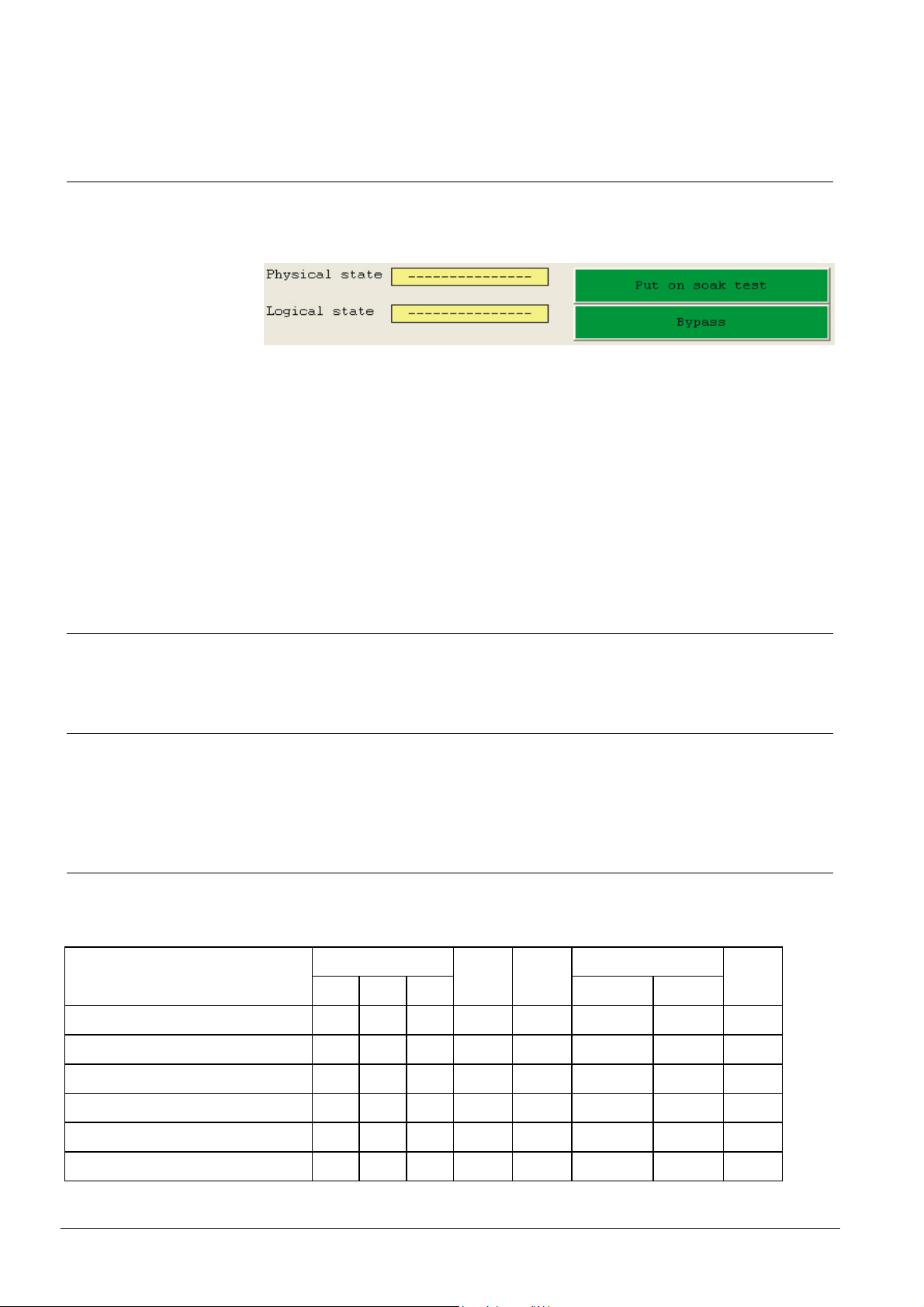
In online modus there is info {yellow field} about the particular physical input status.
In case of maintenance {green field}, there is a possibility to change the logical
state.
Physical State
Logical State
Short circuit
Opened circuit
Alarm The Input triggered an alarm
- - - - - - - - -
Soak Test According to menu Engineer Management “soak test”
In Alarm
In Trouble
Bypassed According to menu Inputs “bypassable”
- - - - - - - - -
6.1 Hardware Input
An example for a hardware Input: I1/MainPCB (Input 1 on Main PCB Board)
6.2 Input Name
Any name consisting of a maximum of 16 characters can be used as the input designation. The letters, number and some special characters are available on the
keyboard of the LCD keypads as multiple assignments.
6.3 Logical Input Type
[TM 511] Not all input types can be assigned to all partitions. The possible input
types depend on the partition type.
Input type
1 Unused
2 Keyswitch Zone latching Full Set Y Y N Y N N N N
Partitions Delay
Main Sub Virtual
Room By-
passabl
e
Chime
Seconds Minutes
3 Keysw. Full set blockschloss Y* Y* N N N N N N
4 Keyswitch Zone latching Part Set Y* Y* N N N N N N
5 Keyswitch Zone Pulse Full Set Y Y N Y N N N N
6 Keyswitch Zone Pulse Part Set Y* Y* N N N N N N
18
Siemens Building Technologies
Fire Safety & Security Products 07.2009

Inputs
Input type
7 Final Setting Push Button Y* Y* Y N N N N N
8 Keypad disabled Y* Y* N N Y N N N
9 Lock Supervision Y* Y* N N Y N N N
10 Geistiger Verschluss Y* Y* N N Y N N N
11 Set/Unset Lock Y* Y* N N N N N N
12 Alarm Memory reset (SI220 only) N N N N N N N N
13 Universal 1 / Universal 2 Y* Y* N N N 0 ... 127 0 ... 127 N
14 External Line Fault N N N N N 0 ... 127 N N
15 Battery Supervision (SI120 only) N N N N N N N N
16 Silent Panic Alarm Y Y N Y N N N N
17 Audible Panic Alarm Y Y N Y N N N N
18 Technical Alarm Y* Y* N N N 0 ... 127 0 ... 127 N
19 Remote Assistance Y* Y* N N N 0 ... 127 0 ... 127 N
20 Fire Y Y Y Y N N N N
Partitions Delay
Main Sub Virtual
Room By-
passabl
e
Chime
Seconds Minutes
21 Tamper Y Y Y Y N N N N
22 BA 24h Y Y Y Y Y N N N
23 Vault Sensor 24H (SI220 only) Y Y Y Y Y N N N
24 BA Full Set only Y Y Y Y Y N N Y
25 BA Full or Part Set ° Y* Y* N N Y N N Y
26 BA Instant P. Set &_ E/Ex F. Set
(BA Instant Part & Full Set) °
27 BA Entry/Exit Full Set ° Y Y Y Y Y 0 ... 127 N Y
28 BA Entry/Exit Full or Part Set ° Y Y N N Y 0 ... 127 N Y
29 BA Exit Terminal Full Set ° Y* Y* Y N Y 0 ... 127 N Y
30 BA Access Zone
(BA Part & Instant Full Set) °
31 BA Entry Route ° Y* Y* N N Y 0 ... 127 N Y
32 BA Loop Follower Full Set ° Y* Y* Y N Y 0 ... 127 N Y
33 BA Loop Follower Full or Part Set ° Y* Y* N N Y 0 ... 127 N Y
34 Emergency Exit 1-5 (For SI120: 1 - 2) Y* Y* N N N N N N
Y = Yes
Y* = Yes, only if USE ROOMS = NO
N = No
Burglar Alarm -> BA All Burglar Alarms, except the 24 hours, has either an entry or exit delay or both, depending on their
DE, UK If the input remains triggered to the end of the delay time on setting Part or Full set, the partition will
All other country
versions
Siemens Building Technologies
Fire Safety & Security Products 07.2009
function.
set again to unset.
If the input remains triggered to the end of the delay time on setting Part or Full set, an immediate
alarm will be triggered.
Y* Y* N N Y 0 ... 127 N Y
Y* Y*
N N Y 0 ... 127
N
Y
19

Inputs
Room Bypass-
35 Panic Pushbuttons of Remote K. N N N N N
36 System Tamper N N N N N
37 Mains Failure N N 0 ... 127 0 ... 127 N
38 Battery Failure N N 0 ... 127 0 ... 127 N
39 Transmission Failure N N N N N
able
Delay Synthetic Input type
Seconds Minutes
Chime
Synthetic Inputs are input types (internally created by the system) and not triggered
by a physical input.
6.3.1 Unused
Unused The input is not monitored in the central control unit.
6.3.2 Keyswitch Zone latching Full Set
Keyswitch Full Set Brief description: external arming; blockschloss
Only one switch should be used per partition because otherwise the positions of the switches do not agree
clearly with the system state.
The assigned partition is switched from unset to full set or vice versa (two fixed states). If the partition is
already part set, this is unset and immediately afterpartitions set to full set. The switch affects an automatic
forced set, i.e. the triggered inputs and inputs which can be bypassed are automatically bypassed. The
partition is, however, not set to full set if the partition is in the "cannot full set" state (e.g. tamper is triggered
etc.)
Trigger input Æ full set.
Set input to normal state Æ unset.
6.3.3 Keysw. Full set blockschloss
Late Homecoming Brief description: Late Homecoming; blockschloss
Only one switch should be used per partition because otherwise the position of the switches does not coincide clearly with the system state.
The assigned partition is switched from full set to unset or vice versa (two fixed states). If, however, the
partition is part set, it is not set to full set but instead it can be set only to unset (late home coming circuit).
The switch causes an automatic forced set, i.e. the triggered inputs and inputs which can be bypassed are
automatically bypassed. The partition is, however, not set to full set if the partition is in the Cannot Full Set"
state (e.g. tamper protection triggered etc.).
From the "Unset" state:
z Trigger input Æ full set.
z Switch input to normal state Æ unset.
From the "Part Set" state:
z Trigger input Æ remains part set.
z Switch input to normal state Æ unset
NOTE
This function is specifically required for German VdS approval.
20
Siemens Building Technologies
Fire Safety & Security Products 07.2009

6.3.4 Keyswitch Zone latching Part Set
Keyswitch Part Set Brief description: internal arming key
Only one switch should be used per partition because otherwise the position of the switches does not coincide clearly with the system state.
The assigned partition is switched from part set to unset or vice versa (two fixed states).
The switch affects an automatic forced set, i.e. the triggered inputs and inputs which can be bypassed are
automatically bypassed. The partition is, however, not set to part set if the partition is in the "cannot part set"
state (e.g. tamper protection triggered etc.)
Trigger input Æ part set.
Switch input to normal state Æ unset.
6.3.5 Keyswitch Zone Pulse Full Set
Pulse keyswitch Full Set Brief description: external arming
Should be used if several devices operate on one partition. The assigned partition is in each case switched
from full unset to set and vice versa.
The state of the input is not assigned to a fixed state of the partition. The state of the partition will change
each activation.
The key causes an automatic forced set, i.e. the triggered inputs and inputs which can be bypassed are
automatically bypassed. The partition is, however, not set to full set if the partition is in the "cannot full set"
state (e.g. tamper protection triggered etc.)
From the "Unset" state:
z Trigger input Æ full set.
z Switch input to normal state Æ no effect.
From the "Full Set" or "Part Set" states:
z Trigger input Æ unset.
z Switch input to normal state Æ no effect.
Inputs
6.3.6 Keyswitch Zone Pulse Part Set
Pulse keyswitch Part Set Brief description: internal arming
Should be used if several setting devices operate on one partition. The assigned partition is in each case
switched from unset to part set and vice versa.
The state of the input is not assigned to a fixed state of the partition. The state of the partition will change
each activation. The key causes an automatic forced set, i.e. the triggered inputs and inputs which can be
bypassed are automatically bypassed. The partition is not set to part set if it is in the "cannot part set" state
(e.g. tamper protection triggered etc.).
From the "Unset" state:
z Trigger input Æ part set.
z Switch input to normal state Æ no effect.
From the "Part Set" or "Full Set" states:
z Trigger input Æ unset.
z Switch input to normal stateÆÞ no effect
6.3.7 Final Setting Push Button
Pulse keyswitch final Set Brief description: external arming; termination of delay time
When this input is triggered, all delay times will be terminated and the complete partition is in full set state.
DE, UK If one of the delayed inputs is triggered, during the “Final Setting Push Button” is pressed, the partition is
All other
country versions
again set to unset.
If one of the delayed inputs is triggered, during the “Final Setting Push Button” is pressed, the partition will be
set and an alarm is triggered.
Alarm triggered Æ ending of the exit delay times
21
Siemens Building Technologies
Fire Safety & Security Products 07.2009

Inputs
6.3.8 Keypad disabled
Keypad Disable The remote keypads of the assigned partition are switched off regardless of set/unset.
Keypad switched off means:
z Keyboard is blocked
z LED’s are dark with the exception of the operating indication
z LCD shows the date and time.
Input triggered Æ Remote keypads of the assigned partition are switched off.
6.3.9 Lock Supervision
Lock Supervision This acts on the release of the block lock output and the cannot full set output. It does not affect the enforce-
ability of the part set.
Input triggered Æ “Blockschloss” output of the assigned partition not released (full set switching is not possi-
ble).
6.3.10 Geistiger Verschluss (GV)
Geistiger Verschluss
(GV)
(Intellectual Lock = IL)
This input function is used if the Sintony is connected to an external intellectual lock device.
Input triggered Æ Intellectual lock requested.
6.3.11 Set/Unset Lock
Unlock Keypads The remote keypads of the assigned partition are access able after an input pulse within a 20 second time
window.
z Keyboard is blocked
z LED’s are dark with the exception of the operating indication
z LCD shows the date and time
z The keypad is not access able in arm state.
Input triggered Æ Remote keypads of the assigned partition are access able within the time window.
6.3.12 Alarm Memory Reset (SI220 only)
Clear Alarm Memory Alarms can be cancelled by this input. This input type can not be assigned to a special partition, therefore all
existing alarms are cancelled when this input is triggered (acknowledged).
6.3.13 Universal 1 / Universal 2
Universal 1 This Input will be activated when it is triggered longer than the configured "delay time” (127 seonds/minutes).
Universal 2 Acts on all “Universal 2” outputs of the assigned partition regardless of the setting. Function as for “Universal
If the delay time is 0, the input is activated immediately.
NOTE
This input will not activate an alarm or buzzer, and there is no entry in the event log.
Link: The output "Universal 1" of the assigned partition will be activated regardless the state of the partition
(full set / part set / unset).
The behaviour of the output can be configured separately in the output settings.
Examples:
“Delay” time zero Æ direct triggering.
“Delay” time = 5 seconds Æ the input must be triggered for more than 5 seconds in order for an activation to
take place.
1”.
22
Siemens Building Technologies
Fire Safety & Security Products 07.2009

6.3.14 External Line Fault
Inputs
External
Line Fault
Acts exactly the same as an internal line fault. Must be used for external communicators so that the parameters which react on
a line fault also function with external communicators. In contrast to an internal line fault, this fault remains triggered until the
input is again in the normal state.
Input triggered Æ line fault
Partition mode:
Unset
Part set
Full set
Effects on the following outputs when the below partition parameters are preset:
6 6 Cannot full set
6 Cannot part set
X X Block lock output not enabled
3 3 X Line monitoring of transmission line
Partition parameters:
X = Triggering regardless of the partition mode.
3 = Triggering only if "transmission" parameter is chosen.
6 = Triggering only if "Forced Set" parameter ->”Not Allowed” is chosen.
6.3.15 Battery Supervision (SI120 only)
Battery Supervision
(SI120 only)
Low battery is detected below 11.6 V. End of low battery is generated above 12 V. Lost of battery is also
detected.
Using additional hardware SMX23/26/29 (approvals), battery is tested every 60 seconds.
Use output ‘Supervision Batterie’ only for triggering SMX23/26/29.
23
Siemens Building Technologies
Fire Safety & Security Products 07.2009

Inputs
6.3.16 Silent Panic Alarm
Silent Panic
Alarm
UK, HU, BE
Silent Panic
Alarm
All other
country
versions
A silent panic alarm is triggered, e.g. neither the outputs for strobe lights nor those for the bells are activated. This input acts
on the panic alarm output regardless of the set state. In the case of physical inputs, a direct alarm takes place when the keys
on the remote keypads are pressed and held for at least 2 seconds (refer to remote keypad instructions).
The output "Panic Alarm" remains stored until alarm is reset.
The "Alarm in Memory" and "Cannot Set” remote keypad LEDs are not activated until a PIN for the corresponding partition is
input.
Input triggered Æ Silent panic alarm in assigned partition.
Partition mode:
Unset
Part set
Full set
Effects on the following outputs when the below partition parameters are preset:
X X Cannot full set
X Cannot part set
X X X Alarm in memory
X X X Panic alarm
X X X Panic alarm system transmission line
X X X Panic alarm partition transmission line
X X X Transmission line input
X = Triggering regardless of the partition mode.
Silent panic alarm is triggered, e.g. neither the outputs for strobe lights nor those for the bells are activated. This input acts
on the panic alarm output, which is activated for 10 seconds on a triggering, regardless of the set state. In the case of physical inputs, a direct alarm takes place when the keys on the remote keypads are pressed and held for at least 2 seconds
(refer to remote keypad instructions).
Input triggered Æ Silent panic alarm in assigned partition.
Partition mode:
Unset
Part set
X X Cannot full set
X Cannot part set
X X X Alarm in memory
X X X Panic alarm output (10 seconds)
X X Block lock output not enabled
X X X Panic alarm system transmission line (10 seconds)
X X X Panic alarm partition transmission line (10 seconds)
X X X Transmission line input (10 seconds)
X = Triggering regardless of the partition mode.
Full set
Effects on the following outputs when the below partition parameters are preset:
24
Siemens Building Technologies
Fire Safety & Security Products 07.2009

6.3.17 Audible Panic Alarm
Inputs
Audible Panic Alarm
UK, HU, BE
Audible Panic Alarm
All other country versions
Panic alarm with activation of the bell and strobe light outputs. This input acts, regardless of the setting,
on the panic alarm output. In the case of physical inputs, a direct alarm takes place when the keys of the
remote keypad are pressed and held for at least 2 seconds (refer to remote keypad instructions). The
"Panic Alarm" output is latched until the alarm is rest.
Input triggered Æ Panic alarm in the assigned partition.
Partition mode:
Unset
Part set
Full set
Effects on the following outputs when the below partition parameters are preset:
X X X External bell
X X 2 Internal bell
X X X Strobe light
X X Cannot full set
X Cannot part set
X X X Alarm in memory
X X X Panic alarm
5 5 5 Buzzer
X X X Panic alarm system transmission line
X X X Panic alarm partition transmission line
X X X Transmission line input
Partition parameters:
X = Triggering regardless of the partition mode.
2 = Triggering only if the internal bell “When Full Set” in the partition parameter is chosen.
5 = Triggering only if “Buzzer On” in the keypad parameter is chosen.
Panic alarm with activation of the bell and strobe outputs. This input acts, regardless of the setting, on
the panic alarm output, which on triggering is activated for 10 seconds. In the case of physical inputs, a
direct alarm takes place when the keys on the remote keypad are pressed and held for at least 2 seconds (refer to remote keypad instructions).
Input triggered Æ Panic alarm in the assigned partition.
Partition mode:
Unset
Part set
Full set
Effects on the following outputs when the below partition parameters are preset:
X X X External bell
X X 2 Internal bell
X X X Strobe light
X X Cannot full set
X Cannot part set
X X X Alarm in memory
X X X Panic alarm (10 seconds)
X X Block lock not released
5 5 5 Buzzer
X X X Panic alarm system transmission line (10 seconds)
X X X Panic alarm partition transmission line (10 seconds)
X X X Transmission line input (10 seconds)
Partition parameters:
X = Triggering regardless of the partition mode.
2 = Triggering only if internal bell parameter “When Part Set” is chosen.
5 = Triggering only if “Buzzer On” in the keypad parameter is chosen.
25
Siemens Building Technologies
Fire Safety & Security Products 07.2009

Inputs
6.3.18 Technical Alarm
NOTE
The technical alarm is displayed after deactivation of an active input at the logical state within Sylcom
"Alarm in memory". This flag can be reset by an engineer reset.
Technical Input
(Technical Zone)
Acts on all technical outputs, remote keypad buzzers and remote keypad alarm LED’s of the assigned
partition regardless of the setting. No alarm memory is set, but instead the alarm is written only to the
memory. Immediately the input is again in its normal state, the technical outputs, remote keypad buzzers
and remote keypad LED’s are reset.
With this input, the delay time acts as an activation time of the input before a technical alarm is triggered.
Examples:
Delay time zero Æ direct triggering.
Delay time = 5 seconds Æ The input must be activated for more than 5 seconds in order for it to be
triggered.
Input triggered Æ Technical alarm in the assigned partition.
Partition mode:
Unset
Part set
Full set
Effects on the following outputs when the below partition parameters are preset:
5 5 5 Buzzer
X X X Technical
X X X Technical transmission line
X X X Technical partition transmission line
X X X Transmission line input
Partition parameters:
X = Triggering regardless of the partition mode.
5 = Triggering only if “Buzzer On” in the keypad parameter is chosen.
6.3.19 Remote Assistance
Remote Assistance Direct triggering of a remote assistance transmission in assigned partition.
Partition mode:
Unset
Part set
Full set
Effects on the following outputs when the below partition parameters are preset:
X X X Remote assistance transmission line
X X X Transmission line input
Partition parameters:
X = Triggering regardless of the partition mode.
26
Siemens Building Technologies
Fire Safety & Security Products 07.2009

6.3.20 Fire
Inputs
Fire Alarm This input will be needed, if a fire warning detector is connected. Shortcut will be detected as an alarm,
4,7 kΩ = Line OK; broken wire = signaled not as a tamper but as a fault. Acts on the fire bells regardless
of the setting. The burglar alarm bells can also be activated.
NOTE
Therefore the physical input type must be set to „fire detector“.
Partition mode:
Unset
Part set
Full set
Effects on the following outputs when the below partition parameters are preset:
1 1 1 External bell
2 2 2 Internal bell
X X X Fire alarm
X X X Alarm in memory
5 5 5 Buzzer
X X X Fire transmission line
X X X Transmission line input
Partition parameters:
X = Triggering regardless of the partition mode.
1 = Triggering only if the external bell “When Part Set” in the partition parameter is chosen.
2 = Triggering only if the internal bell “When Full Set” in the partition parameter is chosen.
5 = Triggering only if “Buzzer On” in the keypad parameter is chosen.
IMPORTANT
The fire zones and its connected fire detectors are only used as fire warning
devices. The intrusion control unit is not replacing a fire alarm system.
6.3.21 Tamper
Tamper Alarm Direct triggering of a Tamper in assigned partition.
Partition mode:
Unset
Part set
Full set
Effects on the following outputs when the below partition parameters are preset:
1 X External bell
X X 2 Internal bell
1 X Strobe light
X X Cannot full set
X Cannot part set
X X X Alarm in memory
X X Block lock not released
5 5 5 Buzzer
X X X Transmission line tamper
X X X Transmission line input
Partition parameters:
X = Triggering regardless of the partition mode.
1 = Triggering only if the external bell “When Part Set” in the partition parameter is chosen.
2 = Triggering only if the internal bell “When Full Set” in the partition parameter is chosen.
5 = Triggering only if “Buzzer On” in the keypad parameter is chosen.
27
Siemens Building Technologies
Fire Safety & Security Products 07.2009

Inputs
6.3.22 BA 24h
Burglar Alarm 24h Brief description: BA 24H
Direct triggering on unset, part and full in the assigned partition.
Partition mode:
Unset
Part set
Full set
Effects on the following outputs when the below partition parameters are preset:
1 X External bell
X X 2 Internal bell
1 X Strobe light
X X Cannot full set
X Cannot part set
X X X Alarm in memory
X X X Burglar alarm
X X Block lock not released
5 5 5 Buzzer
3 3 X Burglar alarm system transmission line
3 3 X Burglar alarm partition transmission line
3 3 X Transmission line input
Partition parameters:
X = Triggering regardless of the partition mode.
1 = Triggering only if the external bell “When Part Set” in the partition parameter is chosen.
2 = Triggering only if the internal bell “When Full Set” in the partition parameter is chosen.
3 = Triggering only if "transmission" parameter is chosen.
5 = Triggering only if “Buzzer On” in the keypad parameter is chosen.
6.3.23 Vault Sensor 24h (SI220 only)
Vault Sensor
(Seismic 24h)
Brief description: BA vault sensor; 24H
Direct triggering on unset, part and full set in the assigned partition.
This input reacts like a 24H burglar alarm line. If, however, an input is programmed to this function, the
“Vibration” output is set for 5 seconds in a random time of between 30 and 90 minutes
With this output, the test generator for structure-borne sound generator can now be triggered in order to
test the alarm inputs of vault sensors. If this input does not trigger after the output has been set, this is
detected by the central control unit which generates a fault (not an alarm).
This means that this type of input operates only in conjunction with a “Vault Sensor” test output.
28
Siemens Building Technologies
Fire Safety & Security Products 07.2009

6.3.24 BA Full Set only
Burglar Alarm Full Set only Brief description: BA external; internal inactive
On part set: No triggering in the assigned partition.
On full set: Direct triggering in the assigned partition.
Partition mode:
Unset
Part set
Full set
Effects on the following outputs when the below partition parameters are preset:
X External bell
X Strobe light
X X Cannot full set
X Alarm in memory
X X Block lock not released
5 Buzzer
X Burglar alarm system transmission line
X Burglar alarm partition transmission line
X Transmission line input
Partition parameters:
X = Triggering regardless of the partition mode.
5 = Triggering only if “Buzzer On” in the keypad parameter is chosen.
Inputs
6.3.25 BA Full or Part Set
Burglar Alarm Full/Part Set Brief description: BA external; internal
Direct triggering on Part and Full set in the assigned partition.
Partition mode:
Unset
Part set
Full set
Effects on the following outputs when the below partition parameters are preset:
1 X External bell
X 2 Internal bell
1 X Strobe light
X X Cannot full set
X Cannot part set
X X Alarm in memory
X X Block lock not released
5 5 Buzzer
3 X Burglar alarm system transmission line
3 X Burglar alarm partition transmission line
3 X Transmission line input
Partition parameters:
X = Triggering regardless of the partition mode.
1 = Triggering only if the external bell “When Part Set” in the partition parameter is chosen.
2 = Triggering only if the internal bell “When Full Set” in the partition parameter is chosen.
3 = Triggering only if "transmission" parameter is chosen.
5 = Triggering only if “Buzzer On” in the keypad parameter is chosen.
29
Siemens Building Technologies
Fire Safety & Security Products 07.2009

Inputs
6.3.26 BA Part Set & BA Entry/Exit Full Set
Instant B.A P. Set &_B.A
E/Ex F. Set
DE, UK If the input remains triggered up the end of the delay time, the partition is again unset.
All other country versions If the input remains triggered up the end of the delay time, the partition remains full set and an alarm is
Brief description: BA external delay; Internal (Reverse function to Input 29)
On part set: Direct triggering in the assigned partition.
On full set: Delayed entry and exit triggering in the assigned partition.
triggered.
Partition mode:
Unset
Part set
Full set
Effects on the following outputs when the below partition parameters are preset:
7 External bell
7 Strobe light
7 Alarm in memory
X X Block lock not released
5 Buzzer
7 Burglar alarm system transmission line
7 Burglar alarm partition transmission line
7 Transmission line input
Partition parameters:
X = Triggering regardless of the partition mode.
5 = Triggering only if “Buzzer On” in the keypad parameter is chosen.
7 = Triggering only after delay.
6.3.27 BA Entry/Exit Full Set
Burglar Alarm Full set
Entry/Exit
DE, UK If the input remains triggered up the end of the delay time, the partition is again unset.
All other country versions If the input remains triggered up the end of the delay time, the partition remains full set and an alarm is
Brief description: BA external delay; Internal inactive
On part set: No triggering in the assigned partition.
On full set: Delayed entry and exit triggering in the assigned partition.
triggered.
Partition mode:
Unset
Part set
Full set
Effects on the following outputs when the below partition parameters are preset:
7 External bell
7 Strobe light
7 Alarm in memory
X X Block lock not released
5 Buzzer
7 Burglar alarm system transmission line
7 Burglar alarm partition transmission line
7 Transmission line input
Partition parameters:
X = Triggering regardless of the partition mode.
5 = Triggering only if “Buzzer On” in the keypad parameter is chosen.
7 = Triggering only after delay.
30
Siemens Building Technologies
Fire Safety & Security Products 07.2009
 Loading...