

Page 1

SG - Station
Planning Guide
AX
© Siemens AG 1996
The reproduction, transmission or
use of this document or its contents
is not permitted without express
written authority. Offenders will be
liable for damages. All rights,
including rights created by patent
grant or registration of a utility
model _or_ design,_are_ reserved.
English
Print No.: RX53-020.021.01.05.02 Doc. Gen. Date: 12.97
Replaces: RX53-020.021.01.04.02
Page 2
0 - 2 Revision
Chapter Page Revision
01 to 405
11 to 205
2 1 to 10 05
31 to 205
41 to 201
51 to 205
61 to 201
71 to 201
81 to 205
SG - Station RX53-020.021.01 Page 2 of 4 Siemens AG
Rev. 05 12.97 TD SD 31 Medical En gineering
Page 3

Contents 0 - 3
Page
1 _______General Notes _________________________________________________1 - 1
General notes . . . . . . . . . . . . . . . . . . . . . . . . . . . . . . . . . . . . . . 1 - 1
Safety . . . . . . . . . . . . . . . . . . . . . . . . . . . . . . . . . . . . . . . . . . 1 - 2
2 _______Room Planning ________________________________________________2 - 1
Room planning example. . . . . . . . . . . . . . . . . . . . . . . . . . . . . . . . .2 - 1
44 - cm SIMOMED monitor . . . . . . . . . . . . . . . . . . . . . . . . . . . . . . . 2 - 2
54 - cm SIMOMED monitor . . . . . . . . . . . . . . . . . . . . . . . . . . . . . . . 2 - 3
44 - cm SIEMENS monitor . . . . . . . . . . . . . . . . . . . . . . . . . . . . . . . 2 - 4
Wall console for 44 - cm and 54 - cm monitor. . . . . . . . . . . . . . . . . . . . . . 2 - 5
Dimensions of RX monitor carriage . . . . . . . . . . . . . . . . . . . . . . . . . . . 2 - 6
MTS - I 1. . . . . . . . . . . . . . . . . . . . . . . . . . . . . . . . . . . . . . . . . 2 - 7
MTS - I 2. . . . . . . . . . . . . . . . . . . . . . . . . . . . . . . . . . . . . . . . . 2 - 8
MTS - I 1 with control display . . . . . . . . . . . . . . . . . . . . . . . . . . . . . . 2 - 9
MTS - I 2 with control display . . . . . . . . . . . . . . . . . . . . . . . . . . . . . 2 - 10
3 _______Preparation for Installation_______________________________________3 - 1
Installation notes for MTS - I . . . . . . . . . . . . . . . . . . . . . . . . . . . . . . 3 - 1
Requirements: . . . . . . . . . . . . . . . . . . . . . . . . . . . . . . . . . . . .3 - 1
General: . . . . . . . . . . . . . . . . . . . . . . . . . . . . . . . . . . . . . . . 3 - 1
Extraction forces: . . . . . . . . . . . . . . . . . . . . . . . . . . . . . . . . . . 3 - 1
Ceiling installation for MTS - I . . . . . . . . . . . . . . . . . . . . . . . . . . . . . . 3 - 2
4 _______System Connections____________________________________________ 4 - 1
n.a. . . . . . . . . . . . . . . . . . . . . . . . . . . . . . . . . . . . . . . . . . . . 4 - 1
n.a. . . . . . . . . . . . . . . . . . . . . . . . . . . . . . . . . . . . . . . . . . . . 4 - 2
5 _______Technical Data _________________________________________________5 - 1
Elektrical data . . . . . . . . . . . . . . . . . . . . . . . . . . . . . . . . . . . . . . 5 - 1
Weights and heat dissipation . . . . . . . . . . . . . . . . . . . . . . . . . . . . . .5 - 1
Environmental conditions . . . . . . . . . . . . . . . . . . . . . . . . . . . . . . . . 5 - 1
Surface color . . . . . . . . . . . . . . . . . . . . . . . . . . . . . . . . . . . . . . 5 - 1
6 _______Transportation Specifications ____________________________________6 - 1
n.a. . . . . . . . . . . . . . . . . . . . . . . . . . . . . . . . . . . . . . . . . . . . 6 - 1
n.a. . . . . . . . . . . . . . . . . . . . . . . . . . . . . . . . . . . . . . . . . . . . 6 - 2
7 _______Project Management ____________________________________________7 - 1
Responsibility of the project manager towards the service contractor . . . . . . . . . 7 - 1
Preparation for installation. . . . . . . . . . . . . . . . . . . . . . . . . . . . . . . . 7 - 1
Installation Protocol . . . . . . . . . . . . . . . . . . . . . . . . . . . . . . . . . . . 7 - 2
Siemens AG RX53-020.021.01 Page 3 of 4 SG - Station
Medical Engineering Rev. 05 12.97 TD SD 31
Page 4

0 - 4 Contents
Page
8 ______ Changes to Previous Version_____________________________________8 - 1
SG - Station RX53-020.021.01 Page 4 of 4 Siemens AG
Rev. 05 12.97 TD SD 31 Medical En gineering
Page 5

General Notes 1
1 - 1
General notes 1
- With distributi on of these revision level, all preceding pl anning guides, Speed - Infos (PG’s) and
drafts lose their validity.
- All layouts i ssued by the Planning Departments must bear a not e referring to the installati on and
delivery conditions of Siemens Medical Engineering Group. The installation and del ivery conditions
must be submitted with the layouts.
- Unless otherwise spe cified, all equipment dimensions i ndicated in the planning guides show a
general tolerance in accordance with I SO 2768 - V.
- Unless otherwise spe cified, all structural dimensi ons indicated in the planning guides show a
general tolerance in accordance with I SO 4172.
- Unless otherwise spe cified, all dimensions are indi cated in "mm".
- The symbol indicates a change (see revision status).
- Orientation poi nts
Points specific to system components to whi ch reference is made when positioning syst em
components to each other or in the room.
The isocenter of a radiographic syste m is always illustrated as the orien tation point.
- Fixpoints
Clearly marked points on syst em components, installation ceil ing, walls or floor on which cable
outlets are located.
Illustration in the dra wings: circle with letter /number-combination.
The cable lengths establish the maximum fixpoi nt distances and thus the maximum distances
between the individual system components.
- Room height
The room height is the distance measured f rom the top surface of the floor to the bot tom surface of
the ceiling structural element s (Unistrut rails) (bottom surfac e of drop ceiling).
Mr. Löchel TD SD 31 Tel. 09191/18 - 8517
Mr. Bürkel TD PS 21 Tel. 09191/18 - 8543
Hotline + 49 (9191) 18 - 8080
Siemens AG RX53-020.021.01 Page 1 of 2 SG - Station
Medical Engineering Rev. 05 12.97 TD SD 31
Page 6

1 - 2 General Notes
Safety 1
- The provisions of the relevant fire protection r egulations must be observed for the premises.
- The system has been devel oped according to IEC 601 - 1 (corresponding to DIN DE 0750, Part 1,
and EN 60601 - 1).
- Minimum dimensions (e. g. room heights, safety distances ) indicated in the planning guides ar e
marked "min."
- Basic streng th against electromagnetic sources of interference.
Result of lightning discharges.
The protection targets of the dif ferent lightning protection ar eas up to the unit connection are also
specified in the IEC 1024, DIN 48810, VDE 0675 and i n the DEMVT recommendations.
SG - Station RX53-020.021.01 Page 2 of 2 Siemens AG
Rev. 05 12.97 TD SD 31 Medical En gineering
Page 7
Room Planning 2
2 - 1
Room planning example 2
Ceiling stand 3D III
*1
MTS - I 2
MTS - I 2
Orientation point
1 : 50
*1 Also applicable for 3D TOP
Siemens AG RX53-020.021.01 Page 1 of 10 SG - Station
Medical Engineering Rev. 05 12.97 TD SD 31
Page 8
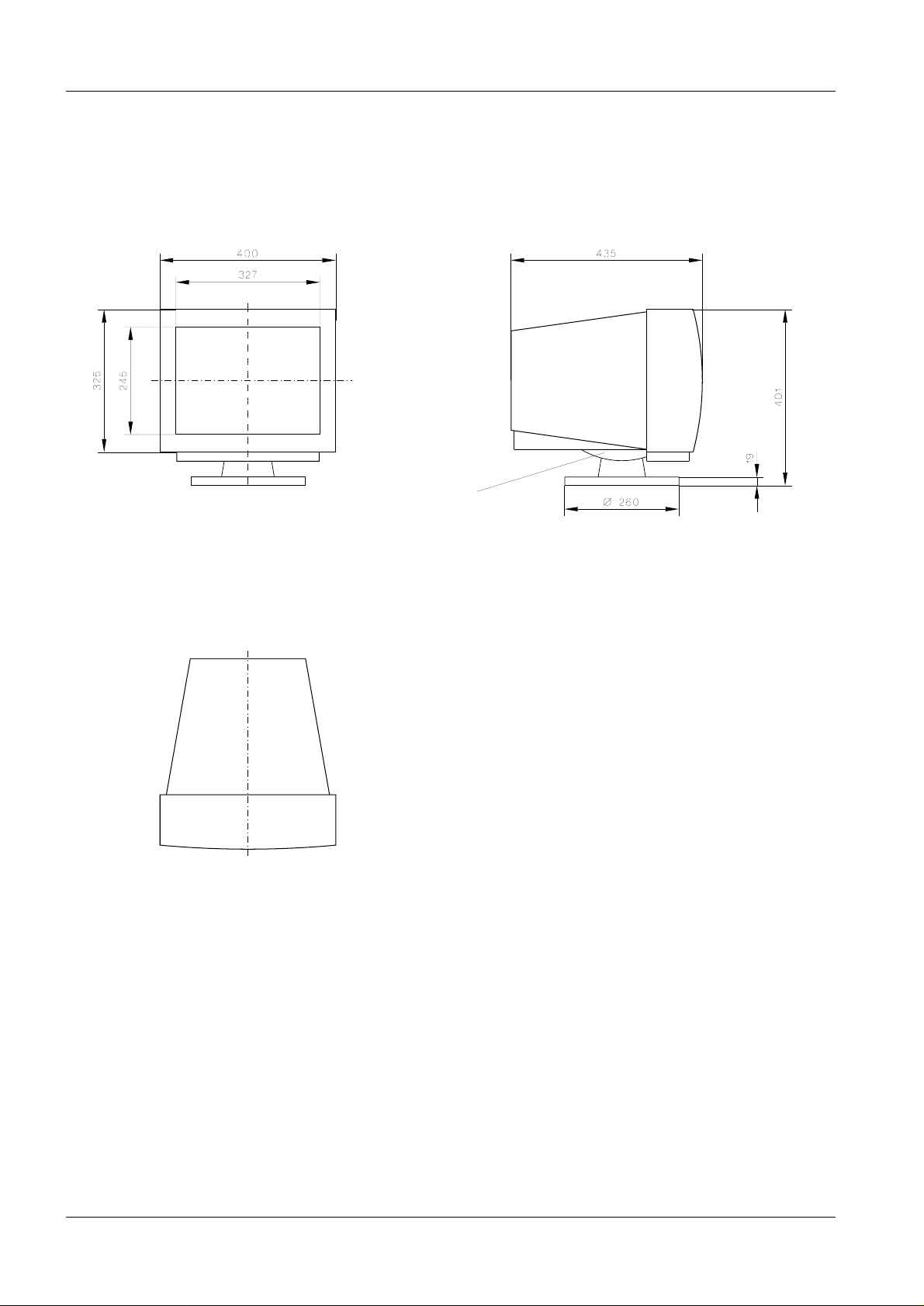
2 - 2 Room Planning
44 - cm SIMOMED monitor 2
Rotatable / tiltable
console (Option)
1 : 10
SG - Station RX53-020.021.01 Page 2 of 10 Siemens AG
Rev. 05 12.97 TD SD 31 Medical En gineering
Page 9
Room Planning 2 - 3
54 - cm SIMOMED monitor 2
1 : 10
Siemens AG RX53-020.021.01 Page 3 of 10 SG - Station
Medical Engineering Rev. 05 12.97 TD SD 31
Page 10

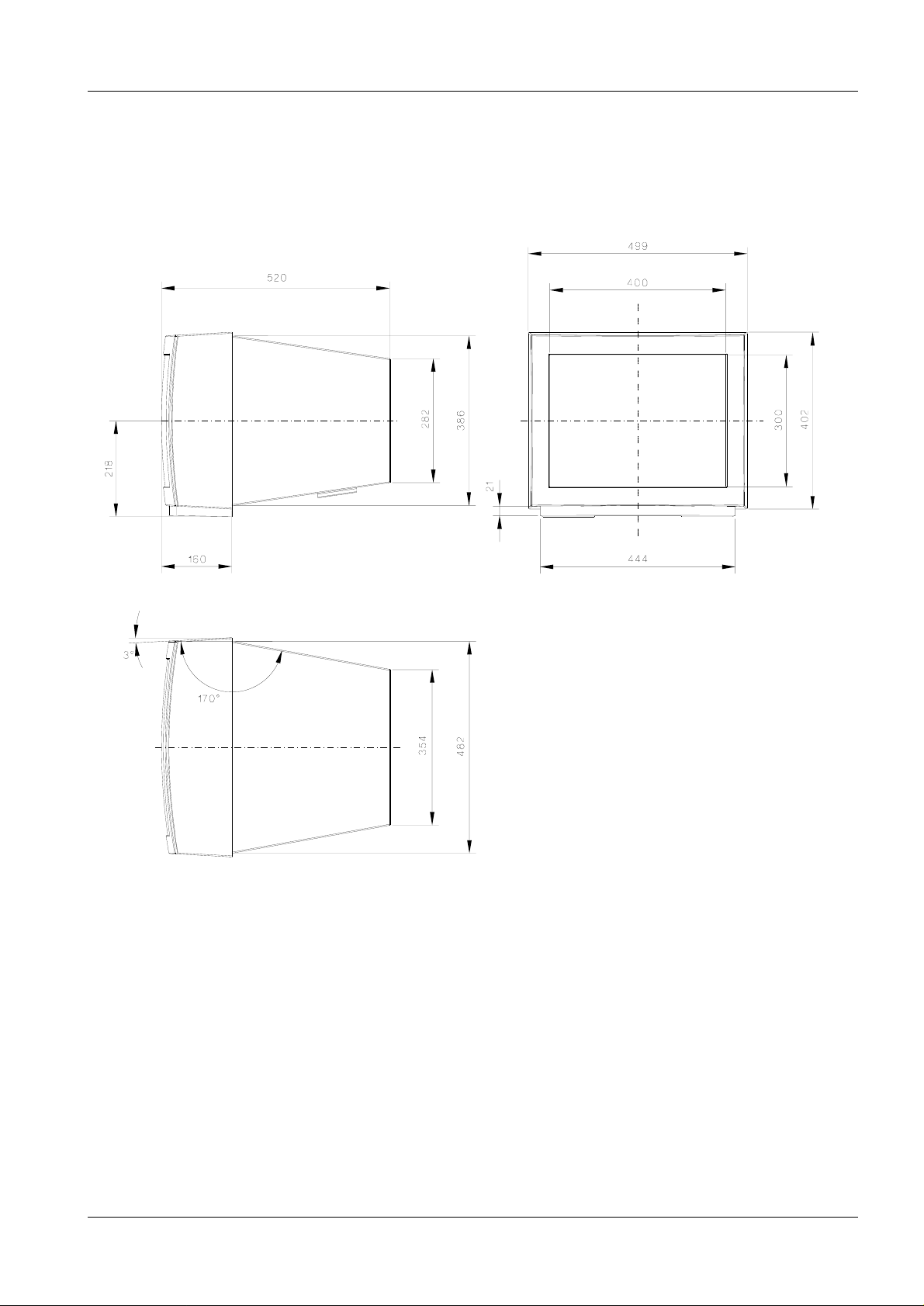
2 - 4 Room Planning
44 - cm SIEMENS monitor 2
1 : 10
SG - Station RX53-020.021.01 Page 4 of 10 Siemens AG
Rev. 05 12.97 TD SD 31 Medical En gineering
Page 11

Room Planning 2 - 5
NOTICE
Wall console for 44 - cm and 54 - cm monitor 2
44 - cm monitor
Rotatable / tiltable
console
View X
1 : 10
4 x Mounting holes
∅ 8.4 mm
1 : 5
When the wall console is used, the monitor is always located on the swivel /
tilt console. Fastening material is included in the delivery (5 wood screws
8 x 60 and S10 Fischer dowels).
Siemens AG RX53-020.021.01 Page 5 of 10 SG - Station
Medical Engineering Rev. 05 12.97 TD SD 31
Page 12

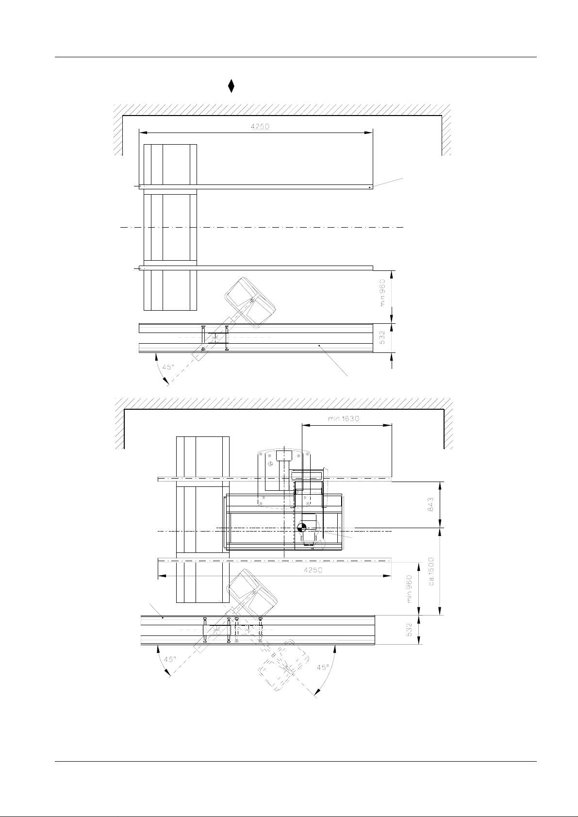
2 - 6 Room Planning
Dimensions of RX monitor carriage 2
imensions: Monitor carriage with 44 - cm SIMOMED monitor
Swivel range
+ 15
o
... - 10
o
Radiation indicator
Display
Adjustment
range for
height cannot
be changed
Radiation indicator
Cable holder
both rear castors
without brakes
Dimensions: Monitor carriage with 54 - cm SIMOMED monitor
both front castors
with brakes
Twin castors
Radiation indicator
Radiation indicator
Cable holder
Display
Cable holder
both rear castors
without brakes
both front castors
with brakes
1 : 20
Twin castors
NOTICE
SG - Station RX53-020.021.01 Page 6 of 10 Siemens AG
Rev. 05 12.97 TD SD 31 Medical En gineering
The control display is only supplied with the SIRESKOP SX system.
Page 13

Room Planning 2 - 7
CAUTION
MTS - I 1 2
*1
*3
*2
Radiation indicator
Cable outlet ∅ min 50 mm
Lift 1028
Stop
alternative cable outlet
1 : 20
*1 5000 mm longitudinal guide rails are used for the POLYSTAR; thus, a movement range of
3920 mm (540 - 4460) results.
*2 The travel can be varied in 5 steps of 45 mm each from 1209 mm to 1389 mm.
o
*3 Lift is 1028 mm at 50
.
If the stop / pivot range of the MTS - I must be on the other side, the cable outlet must also be moved.
Siemens AG RX53-020.021.01 Page 7 of 10 SG - Station
Medical Engineering Rev. 05 12.97 TD SD 31
Page 14
2 - 8 Room Planning
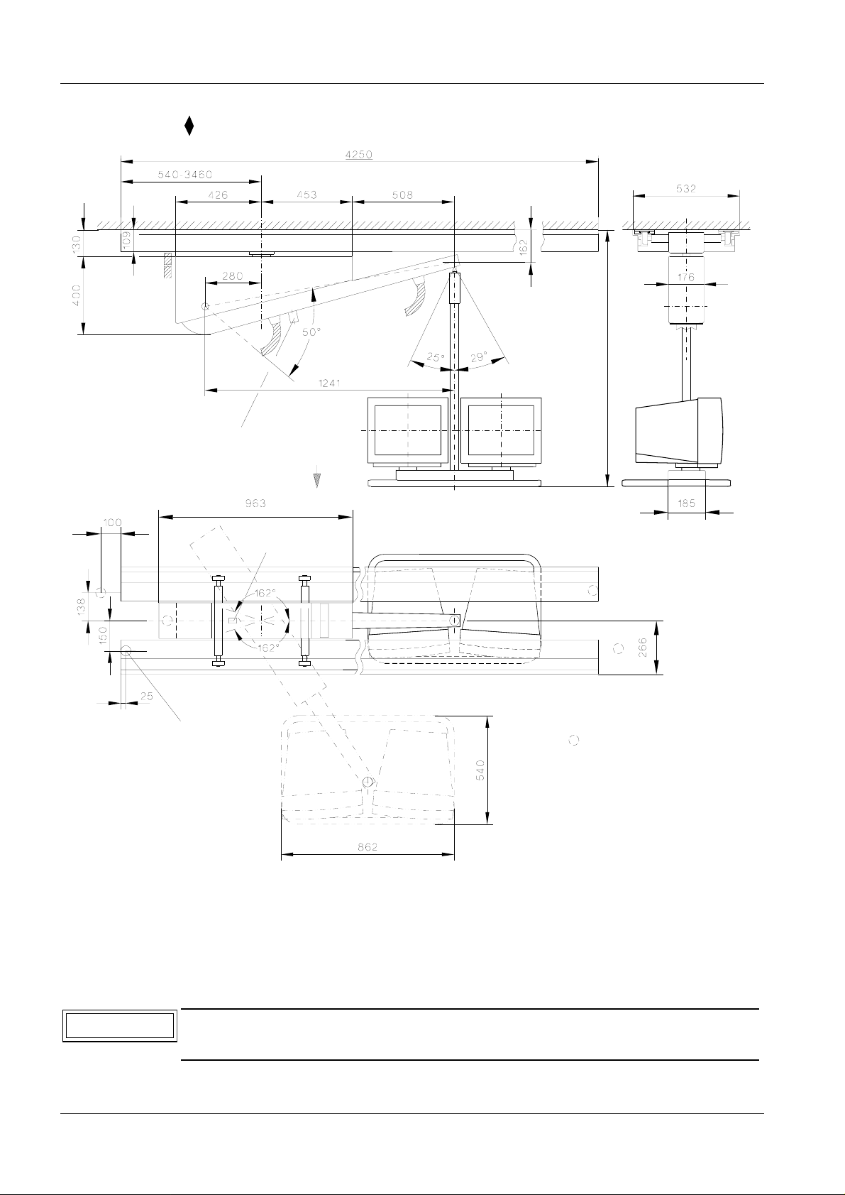
MTS - I 2 2
*1
*3
*2
Radiation indicator
Cable outlet ∅ min 50 mm
Lift 1028
Stop
alternative cable outlet
1 : 20
*1 5000 mm longitudinal guide rails are used for the POLYSTAR ; thus, a movement range of
3920 mm (540 - 4460) results.
*2 The travel can be varied in 5 steps of 45 mm each from 1162 mm to 1342 mm.
o
*3 Lift is 1028 mm at 50
CAUTION
If the stop / pivot range of the MTS - I must be on the other side, the cable out-
.
let must also be moved.
SG - Station RX53-020.021.01 Page 8 of 10 Siemens AG
Rev. 05 12.97 TD SD 31 Medical En gineering
Page 15

Room Planning 2 - 9
NOTICE
CAUTION
MTS - I 1 with control display 2
*2
*1
alternative
cable outlet
Radiation indicator
Lift 1028
Stop
Cable outlet ∅ min 50 mm
1 : 20
*1 The travel can be varied in 4 steps of 45 mm each from 1254 mm to 1389 mm.
o
*2 Lift is 1028 mm at 50
.
The control display is only supplied with the SIRESKOP SX system.
If the stop / pivot range of the MTS - I must be on the other side, the cable outlet must also be moved.
Siemens AG RX53-020.021.01 Page 9 of 10 SG - Station
Medical Engineering Rev. 05 12.97 TD SD 31
Page 16

2 - 10 Room Planning
MTS - I 2 with control display 2
Radiation indicator
alternative
cable outlet
Cable outlet ∅ min 50 mm
Stop
Lift 1028
*2
*1
1 : 20
*1 The travel can be varied in 4 steps of 45 mm each from 1207 mm to 1342 mm.
o
*2 Lift is 1028 mm at 50
NOTICE
CAUTION
The control display is only supplied with the SIRESKOP SX system.
If the stop / pivot range of the MTS - I must be on the other side, the cable out-
.
let must also be moved.
SG - Station RX53-020.021.01 Page 10 of 10 Siemens AG
Rev. 05 12.97 TD SD 31 Medical En gineering
Page 17

Preparation for Installation 3
3 - 1
Installation notes for MTS - I 3
Requirements: 3
- A local subst ructure of Wieland -, Schwerter -, Uni strut or bearer sections.
- Mounting device , part No. 87 63 872 G 2122
General: 3
- The spacing between f ixing points should be max. 675 mm (7 fastening ax es).
- Screws (M10 x 35) and clampin g pieces for 7 fastening axes are supplied.
- An average viewin g level of 1500 - 1600 mm is recommended for the observ er.
- The internal ele ctrical wiring of the MTS - I and the unit t ableside control is carried out i n the factory.
The MTS - I wires end at a plug-in point of ter minal in the rails.
Extractio n for c es: 3
- Maximum static ex traction force per screw 1010 N.
Siemens AG RX53-020.021.01 Page 1 of 2 SG - Station
Medical Engineering Rev. 05 12.97 TD SD 31
Page 18

3 - 2 Preparation for Installation
Ceiling installation for MTS - I 3
Local substructure
1 : 2
Cover plate
Insulating plate
Clamping pieces
Screw M10 x 35
DIN 6912
Longitudinal rail
*1 Maximum rail overhang
100 mm for 4.25 m rail system
(7 mounting points).
Maximum rail overhang
137.5 mm for 5 m rail system
(8 mounting points).
*2 Mounting distance max. 675 mm
Cover
1 : 5
*1
*2
*2
*2
*2
*2
*2
*1
Clamping point
SG - Station RX53-020.021.01 Page 2 of 2 Siemens AG
Rev. 05 12.97 TD SD 31 Medical En gineering
Page 19

System Connections 4
4 - 1
n.a. 4
Siemens AG RX53-020.021.01 Page 1 of 2 SG - Station
Medical Engineering Rev. 01 12.97 TD SD 31
Page 20

4 - 2 System Connections
n.a. 4
SG - Station RX53-020.021.01 Page 2 of 2 Siemens AG
Rev. 01 12.97 TD SD 31 Medical En gineering
Page 21

Technical Data 5
5 - 1
Elektrical data 5
Power supply Input power Internal
fuse
44 - cm SIMOMED monitor
54 - cm SIMOMED monitor
44 - cm SIEMENS monitor
1/N/PE
50/60 Hz
1/N/PE
50/60 Hz
1/N/PE
50/60 Hz
∼ 115/230V ± 10 %
∼ 115/230V ± 10 %
∼ 115/230V ± 10 %
± 1 Hz
± 1 Hz
± 1 Hz
0.7 A bei 230 V
1.3 A bei 115 V
0.7 A bei 230 V
1.3 A bei 115 V
0.27 A bei 230 V
1 x 2 A
fast-blow
1 x 2 A
fast-blow
1.25 A
fast-blow
Weights and heat dissipation 5
Weight [kg] Heat dissipation [W]
44 - cm SIMOMED monitor 22 90
54 - cm SIMOMED monitor 30 90
54 - cm SIEMENS monitor 15 60
RX monitor carriage 72
MTS - I 1 *1
MTS - I 2 *1
145
27
145
27
90
180
1 pair of rail 4.25 m 27
Control display 16
*1 Total weight including longitudinal rails and ceiling carriage without monitor
Environmental conditions 5
SIMOMED monitor Operation Transport Storage
Permissible ambient
temperature
Permissible relative air
humidity
Permissible air pressure 700 hPa - 1060 hPa 400 hPa - 1060 hPa 400 hPa - 1060 hPa
° ... + 35° C- 25° ... + 70° C- 25° ... + 70° C
+10
20 % ... 80 % 20 % ... 80 % 20 % ... 80 %
Surface color 5
Main color
Combination color anthrazit mottled lacquer, Med surface No. 4076
white mottled lacquer, Med surface No. 4146
similar RAL gray white 9002
Siemens AG RX53-020.021.01 Page 1 of 2 SG - Station
Medical Engineering Rev. 05 12.97 TD SD 31
Page 22

5 - 2 Technical Data
This page intentionally left blank .
SG - Station RX53-020.021.01 Page 2 of 2 Siemens AG
Rev. 05 12.97 TD SD 31 Medical En gineering
Page 23

Transportation Specifications 6
6 - 1
n.a. 6
Siemens AG RX53-020.021.01 Page 1 of 2 SG - Station
Medical Engineering Rev. 01 12.97 TD SD 31
Page 24

6 - 2 Transportation Specifications
n.a. 6
SG - Station RX53-020.021.01 Page 2 of 2 Siemens AG
Rev. 01 12.97 TD SD 31 Medical En gineering
Page 25

Project Management 7
7 - 1
Responsibility of the project manager towards the service contractor 7
The scope of the project manager’s responsibilities requi res that he
• is at the installation site when the system arrives
• supports the service contractor in solving problems
• clarifies the final location of the individual components
• checks to ensure that the installation is proceeding as speci fied
• clarifies problems together with the service contr actor prior to the delivery of t he system, e. g.
- establish es the transport route of the tr uck
- establish es the transport route within the bui lding
Preparation for installation 7
Activities that have to be completed before the system’s arrival or installation
• Walls have been finished and painted
• The floor (possibly pre-installation plate) must be prese nt and finished in the system room
• Ceilings are in place
• Room lighting has been insta lled and is ready for use
• All electrical installation has been completed
• None of the construction workers is still working in one of the roo ms
• The rooms have been swept clean with a broom
• A room that can be locked is available as an intermediate storage area f or the components
Siemens AG RX53-020.021.01 Page 1 of 2 SG - Station
Medical Engineering Rev. 01 12.97 TD SD 31
Page 26

7 - 2 Project Management
Installation Protocol 7
• This protocol has to be completed and signed by the installation team (ser vice contractor, SIEMENS
service engineer or project manager) and send back to TD PS 21 Siemens Forchheim.
NOTICE
The supervising SIEMENS project manager
project management.
Furthermore, he is responsible for perfect and proper installation of the
system.
Perform the further work according to the technical documentation (customer
service instructions, installation instructions, etc.).
is responsible for the entire
SG - Station RX53-020.021.01 Page 2 of 2 Siemens AG
Rev. 01 12.97 TD SD 31 Medical En gineering
Page 27

Changes to Previous Version 8
Chapter Page Change
0 - 8 Layout changes, thus a Rev. level change from 04 to 05
1 1-1 and 1-2 Text updated
8 - 1
22-1
2 2-7 to 2-10 Illustration changed and text expanded
3 3-1 Screw thread changed
3 3-2 Ceiling installation of the MTS - I, illustration changed
4 Chapter added (n.a.)
5 5-1 Technical data updated
6 Chapter added (n.a.)
7 7-1 and 7-2 Chapter added
8 8-1 Changes to Previous Version apdated
Cable outlet removed for 3D III, *1 text added and illustration
changed
Siemens AG RX53-020.021.01 Page 1 of 2 SG - Station
Medical Engineering Rev. 05 12.97 TD SD 31
Page 28

8 - 2 Changes to Previous Version
This page intentionally left blank .
SG - Station RX53-020.021.01 Page 2 of 2 Siemens AG
Rev. 05 12.97 TD SD 31 Medical En gineering
 Loading...