

Page 1
Company Confidential
Copyright 2005© Siemens AG
Service Repair Documentation
Level 2.5 – SF65
Release Date Department Notes to change
1.0 05.01.2005 COM MD CC GRM T New document
1.1 27.01.2005 COM MD CC GRM T IRIS codes reviewed
Page 1 of 16
Service Repair Documentation
Level 2.5 – SF65
Page 2

Company Confidential
Copyright 2005© Siemens AG
Introduction
This Service Repair Documentation is intended to carry out repairs on Siemens
repair level 2.5. The described failures shall be repaired in Siemens authorized local
workshops.only
All repairs have to be carried out in an ESD protected environment and with ESD
protected equipment/tools. For all activities the international ESD regulations have to
be considered.
Assembling/disassembling has to be done according to the latest SF65 Level 2 repair
documentation. It has to be ensured that every repaired mobile Phone is checked
according to the latest released General Test Instruction document (both documents
are available in the Technical Support section of the C-market).
Check at least weekly C-market for updates and consider all SF65 related Customer
Care Information
If you have any questions regarding the repair procedures or technical questions
spare not hesitate to contact our technical support team in Kamp-Lintfort, Germany:
Tel.: +49 2842 95 4666
Fax: +49 2842 95 4302
e-mail: st-support@klf.siemens.de
Service Repair Documentation
Level 2.5 – SF65
Page 2 of 16
Page 3

Company Confidential
Copyright 2005© Siemens AG
Table Of Content
1. SF65 Board Layout ..............................................................................................4
2. System Connector ................................................................................................6
3. Display Connector – Board to Board Connector ...................................................7
4. Battery Connector .................................................................................................8
5. White & Red/Green LED.......................................................................................9
6. IRDA Communication Module.............................................................................10
7. Back Up Battery ..................................................................................................11
8. Side TACT Switch...............................................................................................12
9. Sensor Hall .........................................................................................................13
10. Vibra Connector ..................................................................................................14
11. Earphone ............................................................................................................15
12. Flexible Camera Flash Assembly.......................................................................16
Service Repair Documentation
Level 2.5 – SF65
Page 3 of 16
Page 4
Company Confidential
Copyright 2005© Siemens AG
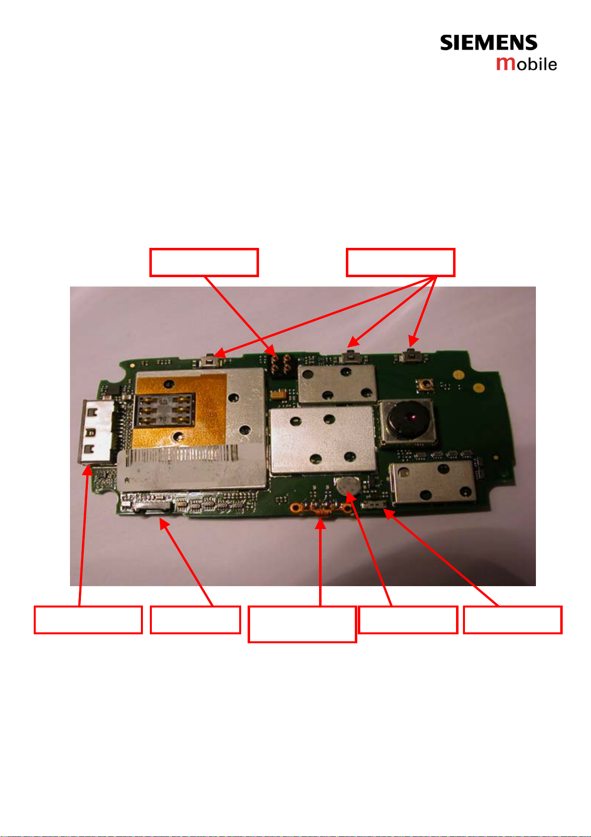
1. SF65 Board Layout
Jigs, Tools and Working materials for all described repairs:
- hot air blower
- soldering gun
- tweezers
- flux
- solder
Battery Connector
Side TACT Switch
IRDA Module System Connector
Service Repair Documentation
Level 2.5 – SF65
Flexible Camera
Flash Assembly
Page 4 of 16
Vibra ConnectorBack Up Battery
Page 5
Company Confidential
Copyright 2005© Siemens AG
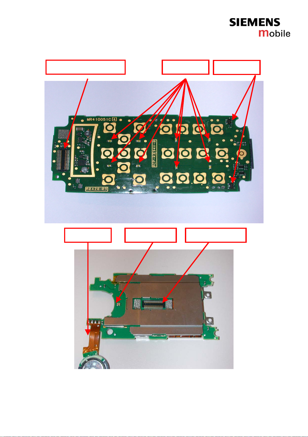
Board to Board Connector
White LED
Sensor Hall
Earphone Red/Green LED Display Connector
Service Repair Documentation
Level 2.5 – SF65
Page 5 of 16
Page 6

Company Confidential
Copyright 2005© Siemens AG
2. System Connector
Fault Symptoms
Customer:
Charging Problems
Problems with external loudspeaker or microphone when using a car kit
Problems with accessories connected at the system connector
System connector
Problems
Watch for oxidation and
damaged pads of the
system connector
okay
Check for dust inside
the system connector
not okay
Check the status of the
system connector visually
okay
okay
Exchange
System connector
not okay
Use the resistor test
function of a multimeter
to check connection
between spring
contacts and soldering
contacts. The value
must be ~0Ω
okay
System Connector
Use soldering iron to remove defective component. Avoid excessive heat! Watch surrounding
components! Resolder new component afterwards.
E-commerce order number: L50634-Z97-C64
Soldering temperature: 240 - 255°C
IRIS Diagnose Code: 46100 Interface/Charging Connector/Mechanical Damage
47300 Interface/Data Interface/Mechanical Damage
4B100 Interface/Headset Connector/Mechanical Damage
Page 6 of 16
Service Repair Documentation
Level 2.5 – SF65
GRT:
No Support
not okay
not okay
SCRAP don´t
send back to
Clean
system connector
- check for twisted or
bended contacts
- check for dry joints
Level 2 Repair
WSC
Page 7

Company Confidential
Copyright 2005© Siemens AG
3. Display Connector – Board to Board Connector
not okay
GRT:
No Support
SCRAP don´t
send back to
- check for twisted or
bended contacts
- check for dry joints
Fault Symptoms
Customer:
Display problems, like missing lines or columns on the LCD or display
contrast problems or illumination problems
B to B connector Problems
Watch for oxidation and
damaged pads of the BtoB
connector
okay
not okay
Check the status of the
BtoB connector visually
okay
Exchange
BtoB connector
Level 2 Repair
Display Connector - Board to Board Connector
Use soldering iron to remove defective component. Avoid excessive heat! Watch surrounding
components! Resolder new component afterwards.
E-commerce order number: L50634-Z97-C58
Soldering temperature: 240 - 255°C
IRIS Diagnose Code: 21000 Display/Performance
22000 Display/Background Illumination
72110 Acoustics/Receiving/Earcap/No Function
72170 Acoustics/Receiving/Earcap/Low Voice Level
75100 Acoustics/Vibra/No Function
Page 7 of 16
Service Repair Documentation
Level 2.5 – SF65
WSC
Page 8

Company Confidential
Copyright 2005© Siemens AG
4. Battery Connector
Fault Symptoms
Customer:
Mobile does not switch on
Battery connector
Problems
Watch for oxidation and
damaged pads of the battery
connector
not okay
Check the status of the
battery connector visually
Exchange
Battery connector
not okay
Use the resistor test
function of a multimeter
to check connection
between spring
contacts and soldering
contacts. The value
must be ~0Ω
Connector BATTERY
Use soldering iron to remove defective component. Avoid excessive heat! Watch surrounding
components! Resolder new component afterwards.
E-commerce order number: L50634-Z97-C59
Soldering temperature: 240 - 255°C
IRIS Diagnose Code: 13000 Battery/Mechanical Damage
GRT:
No Support
okay
okay
not okay
okay
SCRAP don´t
send back to
- check for twisted or
bended contacts
- check for dry joints
Level 2 Repair
WSC
Service Repair Documentation
Level 2.5 – SF65
Page 8 of 16
Page 9

Company Confidential
Copyright 2005© Siemens AG
5. White & Red/Green LED
Fault Symptoms
Customer:
Keypad illumination does not work
LED’s Problems
Watch for oxidation and
damaged pads of the LED’S
not okay
Check the status of the
LED's visually
Exchange
Keypad LED
not okay
Use the diode test
function of a multimeter
to check the status of
the diode. The typical
voltage drop on the
diode is 1.7 V when
testing the diode
function with the
multimeter.
White LED
Use soldering iron to remove defective component. Avoid excessive heat! Watch surrounding
components! Resolder new component afterwards. Attention: Remove Metal Dome Sheet before!!!
E-commerce order number: L50640-L2119-D670
Soldering temperature: 240 - 255°C
IRIS Diagnose Code: 36000 Keys/Illumination
LED Red/Green
Use soldering iron to remove defective component. Avoid excessive heat! Watch surrounding
components! Resolder new component afterwards.
E-commerce order number: L50640-L2125-D670
Soldering temperature: 240 - 255°C
GRT:
No Support
okay
okay
not okay
okay
SCRAP don´t
send back to
- check for dry joints
Level 2 Repair
WSC
Service Repair Documentation
Level 2.5 – SF65
Page 9 of 16
Page 10

Company Confidential
Copyright 2005© Siemens AG
6. IRDA Communication Module
Fault Symptoms
Customer:
No infrared connection possible
IRDA Problems
Watch for oxidation and
damaged pads of the IRDA
not okay
Check the status of the
IRDA visually
Exchange
IRDA
Level 2 Repair
IRDA
Use soldering iron to remove defective component. Avoid excessive heat! Watch surrounding
components! Resolder new component afterwards.
E-commerce order number: L50610-U6189-D670
Soldering temperature: 240 - 255°C
IRIS Diagnose Code: 41100 Interfaces / IRDA / No Function
41300 Interfaces / IRDA / Mechanical Damage
GRT:
No Support
okay
okay
not okay
SCRAP don´t
send back to
- check for mechanical
damage
- check for dry joints
WSC
Service Repair Documentation
Level 2.5 – SF65
Page 10 of 16
Page 11

Company Confidential
Copyright 2005© Siemens AG
7. Back Up Battery
okay
okay
GRT:
No Support
okay
not okay
SCRAP don´t
send back to
- check for dry joints
- Check for twisted or
bended contacts
Level 2 Repair
Fault Symptoms
Customer:
Customer parameter (date and time) are not saved
when battery is removed
Back Up battery
Watch for oxidation and
damaged pads of the Back
Up Battery
not okay
Check the status of the
Back Up Battery visually
Exchange
Back Up Battery
not okay
Use the resistor test
function of a multimeter
to check connection
between input and
output contacts.The
value must be ~0Ω
Back Up Battery
Use soldering iron to remove defective component. Avoid excessive heat! Watch surrounding
components! Resolder new component afterwards.
E-commerce order number: L50628-F2705-Z1
Soldering temperature: 240 - 255°C
IRIS Diagnose Code: 9E000 : Battery / Backup Battery Performance
WSC
Service Repair Documentation
Level 2.5 – SF65
Page 11 of 16
Page 12

Company Confidential
Copyright 2005© Siemens AG
8. Side TACT Switch
okay
okay
GRT:
No Support
okay
not okay
SCRAP don´t
send back to
- check for dry joints
- Check for twisted or
bended contacts
Level 2 Repair
Fault Symptoms
Customer:
Can not take picture, volume/flash does not work
TACT SWITCH
Problems
Watch for oxidation and
damaged pads of the TACT
SWITCH
not okay
Check the status of the
TACT SWITCH visually
Exchange
TACT SWITCH
not okay
Use the resistor test
function of a multimeter
to check connection
between input and
output contacts.The
value must be ~0Ω
SIDE TACT SWITCH
Use soldering iron to remove defective component. Avoid excessive heat! Watch surrounding
components! Resolder new component afterwards.
E-commerce order number: L50615-Z77-C257
Soldering temperature: 240 - 255°C
IRIS Diagnose Code: 34100 Keys / Side / No Function
34300 Keys / Side / Mechanical Damage
34200 Keys / Side / Reduced Functionality
WSC
Service Repair Documentation
Level 2.5 – SF65
Page 12 of 16
Page 13

Company Confidential
Copyright 2005© Siemens AG
9. Sensor Hall
Fault Symptoms
Customer:
Clamshell detection does not work ( camera mode/LCD does not start)
SENSOR HALL
Problems
Watch for oxidation and
damaged pads of the
SENSOR HALL
okay
not okay
Check the status of the
SENSOR HALL visually
okay
Exchange
SENSOR HALL
not okay
Use the resistor test
function of a multimeter
to check connection
between input and
output contacts.The
value must be ~0Ω
okay
SENSOR HALL
Use soldering iron to remove defective component. Avoid excessive heat! Watch surrounding
components! Resolder new component afterwards.
E-commerce order number: L50610-U6190-D670
Soldering temperature: 240 - 255°C
IRIS Diagnose Code:
GRT:
No Support
not okay
SCRAP don´t
send back to
- check for dry joints
- Check for twisted or
bended contacts
Level 2 Repair
WSC
Service Repair Documentation
Level 2.5 – SF65
Page 13 of 16
Page 14

Company Confidential
Copyright 2005© Siemens AG
10. Vibra Connector
Fault Symptoms
Customer:
Vibra does not work
Connector Vibra
Problems
Watch for oxidation and
damaged pads of the
Connector Vibra
okay
not okay
Check the status of the
Connector Vibra visually
okay
Exchange
Connector Vibra
not okay
Use the resistor test
function of a multimeter
to check connection
between input and
output contacts.The
value must be ~0Ω
Connector Vibra
Use soldering iron to remove defective component. Avoid excessive heat! Watch surrounding
components! Resolder new component afterwards.
E-commerce order number: L50634-Z97-C63
Soldering temperature: 240 - 255°C
IRIS Diagnose Code: 75100 : Acoustics / Vibra /No Function
GRT:
No Support
not okay
okay
SCRAP don´t
send back to
- check for dry joints
- Check for twisted or
bended contacts
Level 2 Repair
WSC
Service Repair Documentation
Level 2.5 – SF65
Page 14 of 16
Page 15

Company Confidential
Copyright 2005© Siemens AG
11. Earphone
Fault Symptoms
Customer:
Audio problems
Earphone problems
Watch for oxidation of the
flex Earphone
not okay
Check the status of the
flex Earphone visually
Exchange
EARPHONE
Level 2 Repair
Earphone
Use soldering iron to remove defective component. Avoid excessive heat! Watch surrounding
components! Resolder new component afterwards.
E-commerce order number: L50604-F3090-X923
Soldering temperature: 240 - 255°C
IRIS Diagnose Code: 72110 : Acoustics/Receiving/Earcap/No Function
72110 : Acoustics/Receiving/Earcap/Noise
GRT:
No Support
okay
okay
not okay
SCRAP don´t
send back to
- check for mechanical
damage
- check for dry joints
WSC
Service Repair Documentation
Level 2.5 – SF65
Page 15 of 16
Page 16

Company Confidential
Copyright 2005© Siemens AG
12. Flexible Camera Flash Assembly
Fault Symptoms
Customer:
Flash is not working
Flash Problems
Watch for oxidation of the
flex flash assembly
not okay
Check the status of the
Flex Flash visually
Exchange
Flex Flash
Level 2 Repair
Flex Camera Flash Assembly
Use soldering iron to remove defective component. Avoid excessive heat! Watch surrounding
components! Resolder new component afterwards.
E-commerce order number: L50680-Q7360-F2
Soldering temperature: 240 - 255°C
IRIS Diagnose Code: 9B300 : Functionality /Integrated Camera / Flashlight defective
GRT:
No Support
okay
okay
not okay
SCRAP don´t
send back to
- check for mechanical
damage
- check for dry joints
WSC
Service Repair Documentation
Level 2.5 – SF65
Page 16 of 16
 Loading...